WO2014196630A1 - Chaise - Google Patents
Chaise Download PDFInfo
- Publication number
- WO2014196630A1 WO2014196630A1 PCT/JP2014/065094 JP2014065094W WO2014196630A1 WO 2014196630 A1 WO2014196630 A1 WO 2014196630A1 JP 2014065094 W JP2014065094 W JP 2014065094W WO 2014196630 A1 WO2014196630 A1 WO 2014196630A1
- Authority
- WO
- WIPO (PCT)
- Prior art keywords
- backrest
- support device
- stays
- support
- chair
- Prior art date
Links
Images


Classifications
-
- A—HUMAN NECESSITIES
- A47—FURNITURE; DOMESTIC ARTICLES OR APPLIANCES; COFFEE MILLS; SPICE MILLS; SUCTION CLEANERS IN GENERAL
- A47C—CHAIRS; SOFAS; BEDS
- A47C7/00—Parts, details, or accessories of chairs or stools
- A47C7/36—Support for the head or the back
- A47C7/40—Support for the head or the back for the back
- A47C7/44—Support for the head or the back for the back with elastically-mounted back-rest or backrest-seat unit in the base frame
-
- A—HUMAN NECESSITIES
- A47—FURNITURE; DOMESTIC ARTICLES OR APPLIANCES; COFFEE MILLS; SPICE MILLS; SUCTION CLEANERS IN GENERAL
- A47C—CHAIRS; SOFAS; BEDS
- A47C7/00—Parts, details, or accessories of chairs or stools
- A47C7/36—Support for the head or the back
-
- A—HUMAN NECESSITIES
- A47—FURNITURE; DOMESTIC ARTICLES OR APPLIANCES; COFFEE MILLS; SPICE MILLS; SUCTION CLEANERS IN GENERAL
- A47C—CHAIRS; SOFAS; BEDS
- A47C7/00—Parts, details, or accessories of chairs or stools
- A47C7/36—Support for the head or the back
- A47C7/40—Support for the head or the back for the back
- A47C7/46—Support for the head or the back for the back with special, e.g. adjustable, lumbar region support profile; "Ackerblom" profile chairs
- A47C7/462—Support for the head or the back for the back with special, e.g. adjustable, lumbar region support profile; "Ackerblom" profile chairs adjustable by mechanical means
Definitions
- the present invention relates to a chair, and is particularly suitable for a chair used in an office.
- the first factor that the chair should hold is the comfort of the user.
- comfort is an important factor because chairs used in offices keep people sitting for a long time.
- Documents 1 to 4 describe a structure in which the backrest can be deformed by the body pressure of the seated person, and the backrest is supported by the back frame at three places, the left and right middle parts of the two lower ends of the upper end. It is described.
- the backrest is freely deformed by the body pressure of the seated person, the stability of the body is impaired and the comfort is inferior. In other words, the backrest is required to have a function to firmly support the body.
- the backrest is required to have a function to firmly support the body.
- the body is bent forward, the internal body will be stressed and the burden on the body will increase, so even if the person is not locked, It can be said that it is highly necessary to support and keep the back straight.
- each known document Looking at each known document from the viewpoint of such a stable support function of the body, the back of each known document is supported at three points of the left and right upper part of the upper end and the left and right middle part of the lower end part. It can be said that there is no deformation. However, since the lower part of the backrest is easily deformed, it cannot be said that the function of firmly supporting the body in the non-locking state and holding the back muscles extended is high. That is, each known document may not have a sufficient body support function in a non-locking state.
- the back of the chair often has a resin back plate, but as a means to relieve the feeling of pressure and improve cushioning and fit, the back plate is made to have a flexible structure.
- the applicant of the present application disclosed in Document 5 that the body support portion is formed of a multi-stage strip group by providing left and right laterally elongated grooves in multiple stages on the back plate.
- each strip is provided with thin trimming grooves at the left and right ends in order to facilitate deformation.
- Document 6 discloses a back plate having a form similar to a honeycomb structure
- Document 7 has a net-like structure by regularly arranging cross-shaped holes and straight holes. A backrest is disclosed.
- the body support part of the backrest is formed as a mesh structure, and the group of thin lines constituting the body support part is bent, so that the group of line extends and deforms due to body pressure. Therefore, the entire body support portion can be deformed so as to be recessed rearward.
- the waist is firmly supported because it is held in an appropriate posture with the back straight, but the flexibility of the backrest is high. If too much, the body cannot be supported stably.
- Documents 6 and 7 are a kind of network structure and have a structure that is easily deformed as a whole, it can be said that there is room for improvement in terms of stable support of the body, although the cushioning property is high.
- the band plate of Document 5 is excellent in supporting stability of the body because it does not stretch and deform excessively, but there is room for improvement in terms of flexibility because there is a limit to the elongation of each band plate. I can say.
- the present invention has been made against the background of the present situation, and intends to provide a chair that is improved in use value and improved.
- the present application includes many improved configurations, and may be provided.
- the present invention has been made against the background of such a situation, and aims to provide an improved backrest.
- This application is composed of a group of inventions having a hierarchical and planar spread, and the typical examples are specified as the first to fifteenth inventions.
- the first invention constitutes a superordinate concept, and includes, as a basic configuration, a seat, a backrest, and a rigid structure back frame arranged with a space behind the backrest.
- the backrest includes a first support device disposed at a height near the upper end of the backrest, and a second support device disposed lower than the first support device and higher than the seat surface. It is attached to the back frame, and the first support device is attached to a portion of the backrest that is close to the left and right intermediate portion.
- the 1st support apparatus should just be attached to the upper end of the backrest, or its vicinity, and the backrest may protrude on the 1st support apparatus. That is, the mounting position of the first support device has a vertical width. The same applies to the second support device.
- the backrest is supported by three points, that is, the left and right middle part of the upper end part and the two right and left parts below it. And, when the user is sitting without leaning on the backrest to perform desk work such as PC operation, the lumbar part etc. can be stably supported by the part supported by the left and right points of the backrest. it can. Therefore, the state where the back is stretched can be accurately maintained, and the user can take an appropriate working posture.
- the upper end portion (or upper portion) of the backrest protrudes to the left and right outer sides of the first support device and becomes a free end. That is, the left and right ends of the upper end (upper part) of the backrest are free ends that are not supported from the back. Therefore, by making the upper part of the backrest deformable with body pressure, it is possible to deform the backrest following the torsion of the body while leaning against the backrest, and in this state Can contribute to the improvement of comfort.
- the second invention is an example of the development of the first invention.
- the first support device is deformed when the body pressure of the seated person is applied to the backrest, and the upper portion of the backrest is allowed to shift backward.
- the second support device has rigidity that does not essentially bend and deform even when the body pressure of the seated person is applied, or is elastically deformed by the body pressure of the seated person.
- the degree is an elastic strength lower than the elastic strength of the first support device.
- the first support device since the first support device has a spring property, it is allowed that the upper part of the backrest moves so as to approach the back frame in a state where the person leans on the backrest. That is, the reaction force of the first support device acts on the upper portion of the backrest from behind, and this reaction force provides comfort to the user as a cushioning action.
- the torsional deformation of the backrest is allowed by the deformation of the first support device, the following deformability when the person twists the body to the right or left while leaning on the backrest is also improved.
- the second support device hardly deforms or is deformed by the body pressure of the seated person, the degree of support is smaller than that of the first support device.
- the backrest may be in a leaning state. Since the body is stably supported in the lower part, it is possible to improve comfort by preventing the body from moving excessively.
- the third invention is a development example of the first invention or the second invention.
- the first support device is vertically long in a side view, while the second support device is separated into two on the left and right. These left and right second support devices are inclined so that the distance between the left and right second support devices increases toward the front in plan view.
- the first support device and the second support device can adopt various modes.
- the portion extending between the back frame and the backrest of the first support device and the second support device is simple. Since a simple plate-like form is sufficient, there is an advantage that the structure can be simplified.
- the first support device 12 is long in the vertical direction, it can be easily deformed so as to bend backward due to the body pressure of the seated person, so that the followability to the body change and the cushioning property can be improved.
- the fourth invention is a development example of the first invention or the second invention.
- the back frame has a pair of left and right vertically long members, and the left and right vertically long members become narrower as they go upward.
- the upper end is integrally connected via a connecting portion, the first supporting device is attached to the connecting portion of the back frame, and the second supporting device is attached to left and right vertically long members.
- the specific matter of the fourth invention can also be applied to the third invention.
- the back frame can be composed of a single member located at the left and right middle part of the backrest, or can adopt an inverted U shape having left and right vertical parts. Adopting the inverted V-shaped form) has an advantage of ensuring high strength while being simple.
- the fifth invention is a development example of the first invention or the second invention.
- the backrest has a resin main member attached to the back frame, and the main member constitutes the outer periphery.
- the specific matters of the fifth invention can also be applied to the third invention or the fourth invention.
- the backrest can adopt various structures, in the fifth invention, since the main member is an integrally molded product, it is possible to save the manufacturing effort compared to the case where the frame body and the body support portion are configured as separate members. In addition, quality variations can be prevented.
- the body support portion is provided on the frame body at a constant level.
- the body support portion is made of a flexible material such as a mesh material, and the flexible material is used as the frame body. It is also possible to adopt a mounting configuration. In any case, it is preferable that the frame is deformed flexibly by the body pressure of the seated person.
- the backrest can be constituted only by the main member, and the body pressure of the seated person can be directly received by the main member.
- the front surface of the main member is provided. Is provided with a cushion, and at least the cushion is covered with a skin material.
- the softness to a body is securable with a cushion.
- the seventh invention is also a development example of the fifth invention.
- the lower end of the main member is located near the seating surface, and the lumbar support member that supports the waist of the seated person on the front or rear surface of the main member. Further, the main member is attached to the second support device at a position slightly above the lumbar support member.
- the specific matters of the seventh invention can also be applied to the first to fourth inventions and the sixth invention.
- the lumbar support member is provided as in the seventh invention, the seated person's waist can be accurately supported, which can contribute to the seated person holding an appropriate posture. And since the 1st support apparatus is attached to the main member on the lumbar support member, it can prevent that the horizontal width of the main member becomes large too much. Moreover, since the attachment part of a 2nd support apparatus and the attachment part of a lumbar support member are near, the rigidity of the location of the attachment part of a lumbar support member among main members can also be raised, and a user's body stability is improved. You can contribute even more.
- the eighth invention is a development example of the first invention or the second invention, and in this invention, the backrest tilts backward when the body pressure of the seated person is applied.
- the eighth invention is applied to a rocking chair, it can of course be applied to the third to seventh inventions. In a rocking chair, it is widely performed to link the seat to the backrest.
- the present invention is naturally applicable to such a synchro-type chair.
- the present invention is particularly effective under the eighth invention.
- the backrest of the ninth invention is composed of a plurality of areas where the body support portion on which the body pressure of the seated person is applied is divided into left and right with a certain distance, and each of the areas is a horizontally long Consists of book stays, stays in adjacent areas are shifted up and down, and adjacent stays in adjacent areas are connected by connecting pieces that are inclined in front view. The inclined postures of the connecting pieces adjacent to each other in the vertical direction are reversed.
- the body support portion is basically deformed so as to extend in the left-right direction, and therefore, the body support stability is excellent. That is, since the deformation of the body support part is directional, the body support part does not deform excessively following the movement of the body, and the body support stability is excellent.
- the body support part is in the same state as extending and deforming substantially in the left-right direction. Thereby, high cushioning properties can be secured. In addition, each stay bends, twists and deforms, so it has excellent fit to the body.
- the group of stays is vertically oriented. That is, according to the tenth aspect of the present invention, the body support portion to which the body pressure of the seated person is applied is composed of a plurality of areas separated vertically by a certain distance, and each of the areas has a plurality of vertically long stays.
- the stays in the adjacent areas are shifted to the left and right, and the adjacent stays in the adjacent areas are connected by connecting pieces that are inclined in a front view. The inclined postures of adjacent connecting pieces are reversed.
- the body support portion extends and deforms easily in the left-right direction, but basically the same effect as the ninth invention is exhibited.
- the eleventh invention is a preferred development of the first invention or the second invention.
- the width of the connecting piece is smaller than the width of the stay in a front view. If comprised in this way, a deformation
- the twelfth invention is a specific example of the ninth invention, and in this invention, the bases of the connecting pieces adjacent to each other vertically or horizontally are close to each other, and therefore the connecting pieces adjacent vertically or horizontally are V-shaped. Forms.
- the number of connecting pieces may be reduced and the strength may be lowered.
- the connecting pieces are in a continuous state without interruption, the number of connecting pieces can be increased, and as a result, the strength of the body support portion can be ensured.
- the center area has a center area located at the left and right center part, and left and right side areas arranged on both right and left sides. It is composed of a group of center stays, the side area is composed of side stays, and a group of connecting pieces connecting the group of center stays and the group of side stays forms a zigzag form.
- the number of areas in which the body support part is configured can be arbitrarily set, but if there are too many areas, the number of connecting pieces also increases, so there is a concern that if some measure is not taken, the flexibility will become too high .
- it is composed of one center area and two side areas as in the thirteenth aspect of the invention it is preferable because the body support stability and cushioning properties can be well matched.
- the fourteenth aspect of the present invention is a preferred embodiment of the ninth aspect of the present invention.
- the density of the stay is high at the lumbar support portion that supports the seated person's waist.
- the seated person's waist is accurately supported, which is beneficial for improving the stability of the user's body.
- means for increasing the rigidity of the lumbar support portion means different from the fourteenth invention such as increasing the plate thickness of the stay can be adopted.
- each stay has a plate-like shape in which the front and rear thicknesses are smaller than the vertical width.
- Left and right longitudinal ribs are formed, and the ribs are also integrally connected to the connecting piece.
- the necessary bending strength can be ensured while making each stay as thin as possible. Therefore, it is suitable for saving material (resin). Further, since the rib and the connecting piece are connected, it is possible to prevent the end portion of the stay from being bent intensively and to realize smooth deformation. There is also an advantage of improving durability by preventing stress concentration. In addition, providing a rib on the rear surface of the stay can also be applied to the tenth invention.
- the present invention improves comfort in the state of leaning on the chair. Furthermore, the strength of the chair can be ensured, and the manufacturing labor can be saved, and variations in quality can be prevented.
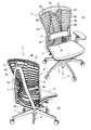
- FIG. 1A and 1B are views showing the overall appearance of a chair according to an embodiment, in which FIG. 1A is a perspective view seen from the front, and FIG. 1B is a perspective view seen from the rear.
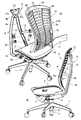
- 2A and 2B are views showing the overall configuration of the chair, in which FIG. 2A is a partially separated perspective view, and FIG. 2B is a side view.
- 3A and 3B are separated views of the main part, in which FIG. 3A is a view showing a state in which the backrest is shifted in a normal posture, and FIG. 3B is a view in which the backrest is horizontally turned and separated.
- 4A and 4B are diagrams showing the relationship between the support device and the back frame, in which FIG.
- FIG. 4A is a perspective view of the first support device and the back frame separated
- FIG. 4B is a view of the first support device, the second support device, and the backrest.
- An exploded perspective view, (C) is an exploded perspective view of the second support device and the backrest.
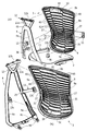
- 5A and 5B are separation views showing the relationship between the first support device and the backrest.
- 6A and 6B are separation views showing the relationship between the second support device and the backrest.
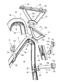
- FIG. 7 is an explanatory view of a lumbar support member
- (A) and (B) are separated perspective views
- (C) is a plan view of a backrest.
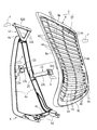
- FIG. 8 is a front view of the backrest.
- FIG. 9 is a perspective view of the backrest as seen from the front.
- FIG. 10 is a perspective view of the backrest as seen from behind.
- FIG. 11 is a separation diagram for explaining the function.
- the chair includes a leg device 1, a seat 2, and a backrest 3 as main elements, and the backrest 3 is attached to a back frame 4 disposed behind the leg device 1.
- the leg device 1 includes a leg support 5 in a vertical posture and a center tube 6 that supports the leg column 5, and five branch arms extend in the radial direction from the center tube 6.
- a caster is attached to the tip of each branch arm.
- the leg support 5 is composed of an extendable gas cylinder having an inner cylinder and an outer cylinder. As shown in FIG. 2B, a base 7 is attached to the upper end of the leg support 5 and the back frame 4 is attached to the base 7. Are connected via a joint member 8 so as to be tiltable backward. The back frame 4 and the joint member 8 can be integrated.
- the inner cylinder and the outer cylinder constituting the leg column 5 are rotatable relative to each other. Therefore, the base 7 (and the seat 2 and the backrest 3) can be rotated horizontally.
- the base 7 incorporates a locking spring that elastically supports the rearward tilting of the back frame 4.
- the seat 2 is attached so that an intermediate member (not shown) provided on the base 7 can be moved backward while being tilted rearward around the front portion.
- the intermediate member and the joint member 8 are connected to each other so as to be capable of relative movement with a horizontally long shaft. For this reason, the seat 2 tilts backward while moving backward in conjunction with the backward tilt of the backrest 3.
- the backrest 3 has a main member manufactured by an injection molding method using a resin such as polypropylene as a material.
- a resin such as polypropylene
- the backrest 3 and the main member must be distinguished.
- the main member constitutes the entire backrest 3, and therefore the two are distinguished. The profit is thin. Therefore, in order to simplify the explanation, the wording of the backrest 3 is used without using the wording of the main member.
- the backrest 3 is composed of a frame body 9 that forms the outer periphery of the backrest 3 and a body support portion 10 that is positioned inside the frame body 9.
- the frame 9 has a pair of side members 9 a that constitute both the left and right sides, a horizontally long upper member 9 b that constitutes the upper end portion, and a left and right horizontally elongated lower member 9 c that constitutes the lower end. It is formed in a close form.
- the lower end of the backrest 3 is located near the seat surface.
- a lumbar support member 11 that supports the waist of the seated person is disposed on the front surface of the backrest 3 at a height corresponding to the waist of the seated person. Since the height and preference of the seated person varies, the lumbar support member 11 can be adjusted in height.
- the backrest 3 of the present embodiment has a constricted shape so that the attachment portion of the lumbar support member 11 is the narrowest.
- the lateral width is substantially constant, the inverted trapezoidal shape having a wide upper end and a narrow lower end, or an inverted base having a narrow upper end and a wide lower end Arbitrary forms, such as a shape, can be adopted.
- the back frame 4 has left and right vertically long members 4a that are inclined so as to approach each other as the distance therebetween increases.
- the left and right vertically long members 4a are integrally connected at the upper ends via connecting portions 4b.
- the left and right vertical members 4a form an inverted V shape.
- the lower ends of the left and right vertically long members 4a are integrally connected via a lower stay portion 4c.
- a forward-facing arm portion 4d is integrally provided at the lower ends of the left and right vertically long members 4a.
- the forward arm portion 4d and the lower stay portion 4c are connected to the joint member 8 shown in FIG.
- the longitudinal member 4a of the back frame 4 is formed in an L-shaped cross section having a back plate and a side plate. For this reason, although it is lightweight, it has a structure resistant to the front-rear direction, the left-right direction, and torsion.
- the back frame 4 of the present invention employs a resin molded product or an aluminum die-cast product, but can also be manufactured using a metal plate or metal pipe as a material. It is also possible to make a composite product of different materials. In addition, it is not necessarily an integral structure, and for example, the left and right vertically long members 4a may be separately manufactured and connected at the upper end, and may be configured by a plurality of parts. It is also possible to employ a shell structure product for the back frame 4.
- the left and right intermediate portions of the upper member 9 b of the backrest 3 are attached to the connecting portion 4 b at the upper end of the back frame 4 via the first support device 12.
- the left and right side members 9 a are attached to the vertically long member 4 a of the back frame 4 via the second support device 13 at a portion above the attachment portion of the lumbar support member 11. This point will be described in detail below.
- the first support device 12 has two spring portions 12a arranged in a V shape when viewed from the front.
- a left and right horizontally long upper mounting portion 12b is integrally connected to the upper end of the spring portion 12a.
- the lower attachment part 12c which protruded back is integrally connected to the lower end of the right-and-left spring board part 12a.
- the first support device 12 is manufactured by injection molding using a resin such as polypropylene, and the spring plate portion 12a has a vertically long posture, but is wide in a front view and narrow in a side view. Forms. For this reason, it can be easily bent and deformed by the force from the front.
- the lower mounting portion 12c is formed in a horizontally long block shape (boss shape).
- a rear first concave portion 15 of a forward opening into which the lower mounting portion 12c is fitted is formed in the connecting portion 4b of the back frame 4.
- the lower attachment portion 12c is fixed to the rear first recess 15 by a first bolt 16 inserted from below.
- a nut insertion hole 17 for setting a nut into which the first bolt 16 is screwed is opened backward in the mounting portion 12c of the first support device 12.
- the upper member 9b of the backrest 3 has an inner / outer triple structure having an outer wall, an inner wall 18 and an intermediate wall 19 (drawing modification), and therefore, two long grooves opened rearward. 20 is formed.
- the front side 1st recessed part 21 in which the upper attachment part 12b of the 1st support apparatus 12 fits is formed by notching the left-right intermediate part of the inner wall 19, for example.
- the upper mounting portion 12b of the first support device 12 is fixed to the upper member 9b by a second bolt 22 inserted from below (because the reference numeral is 16 in the drawing, it is corrected).
- the upper member 9b of the backrest 3 is formed with a nut holding portion 23 that opens backward.
- a stopper piece 24 is provided so as to protrude upward from the nut holding portion 23 of the upper member 9b.
- the second support device 13 is manufactured from a highly rigid resin such as nylon resin. As shown in FIGS. 5B and 5C, the second support device 13 includes a belt-like arm portion 13a that is gently bent in a waveform in plan view. A rear boss portion 13b is integrally provided at the rear end of the arm portion 13a, and a front boss portion 13c is integrally provided at the front end of the arm portion 13a.
- the arm portion 13a has rigidity that is not easily deformed by the body pressure of the seated person (however, it may be slightly deformed).
- the rear boss portion 13b is fitted into a rear second concave portion 25 provided in the longitudinal member 4a of the back frame 4.
- a third bolt 26 is inserted into the rear second concave portion 25 from below.
- a nut (not shown) into which the third bolt 26 is screwed is incorporated in the rear boss portion 13 b of the second support device 13.
- the rear boss portion 13b is provided with a flange 13d that overlaps the opening edge of the rear second concave portion 25.
- the side member 9a of the backrest 3 is formed with a front second concave portion 27 into which the front boss 13c of the second support device 13 is fitted.
- the front second concave portion 27 has a substantially box-like appearance, and a bolt hole 28 through which a bolt (not shown) passes is formed in the inner wall 27a.
- a nut mounting groove 29 is provided in the front boss portion 13 c of the second support device 13, and a bolt is screwed into a nut disposed in the nut mounting groove 29.
- the inner plate 25a of the front second concave portion 27 is formed with a step portion 30 for increasing the strength by thickening the bolt hole 28 portion.
- a notch 31 is formed in the front boss 13c of the second support device 13 so as to overlap the step 30 of the front second recess 27.
- the front boss portion 13 c of the second support device 13 is provided with a flange 13 e that overlaps the opening edge of the front second concave portion 27.
- the lumbar support member 11 is a molded product made of a resin, and is made of a material having a certain degree of elasticity, such as polypropylene.
- the lumbar support member 11 has a laterally long shape that crosses the backrest 3 and is gently curved in a concave shape in a plan view. Further, the lumbar support member 11 is slightly curved in a forward projecting shape when viewed in a longitudinal side view.
- a slide boss body 34 is formed integrally with the left and right ends of the lumbar support member 11 and protrudes backward in a prismatic shape.
- the slide boss body 34 is slidably fitted to a vertically long guide frame portion 35 provided on the side member 9 a of the backrest 3.
- the inner periphery of the guide frame portion 35 is configured by a plate portion, and the above-described front second concave portion 27 is integrally connected to the upper end of the guide frame portion 35.
- a block-like forward projecting portion 36 a provided on the knob 36 is fitted to the rear end of the slide boss body 34.
- the forward projecting portion 36a of the knob 36 is fixed to the slide boss body 34 by a bolt (not shown).
- the slide boss body 34 is provided with a nut insertion groove 37.
- the lumbar support member 11 can hold the height stepwise, and as a height adjusting means, as shown in FIG. Provided.
- a lumbar support member on the backrest, it is generally arranged on the back side of the cushion or the mesh material. However, if a cushion or mesh material is interposed between the lumbar support member and the body, it may feel unsatisfactory for a person who seeks a strong “feel”. In some cases, such as when the backrest is not provided with a cushion or mesh, the lumbar support member must be disposed in front of the back plate.
- Japanese Patent Publication No. 2008-237333 discloses that a backrest is composed of a frame portion and a back plate inside the frame, and a plurality of slits are provided in the back plate. It is disclosed to arrange in front.
- a clip-type handle that is fitted to the frame portion from the outside is integrally provided at both left and right end portions of the lumbar support member, and the frame portion is elastically held by the handle.
- the handle protrudes from the left and right outside of the frame portion, so that a person's clothes are caught on the handle or an object hits the handle and the handle is damaged. Is concerned. Further, since the handle only holds the height by friction, the lumbar support member may slide down or rise up due to the body pressure of the seated person.
- the slide bosses 34 provided at the left and right ends of the lumbar support member 11 penetrate the guide frame portion 35 of the frame body 9, so that the knob 36 protrudes from the left and right outer sides of the frame body 9. Can be arranged so that there is no. Thereby, it can prevent or remarkably prevent that clothes are caught on the knob 36 or an object hits it.
- the guide frame portion 35 since it is easy to provide the guide frame portion 35 with a means for holding the height of the stopper hole 38 for adjusting the height, the lumbar support member 11 can be held at a desired height and cannot be moved.
- the height adjusting means can adopt various configurations.
- an elastic member that fits and detaches from the guide frame portion 35 may be provided in the block-like forward projecting portion of the knob 36. Since the guide frame portion 35 has a certain width in the front-rear direction, there is no reduction in strength due to the penetration of the slide boss body 34.
- the knob 36 can be simply plate-shaped and screwed to the slide boss body 34.
- the body support unit 10 includes a group of horizontally long side stays 40 connected to the left and right side members 9 a and a group of horizontally long center stays 41 positioned between the group of side stays 40.
- the groups of both stays 40, 41 are arranged in a vertically displaced state.
- a center area is constituted by a group of center stays 41, and a side area is constituted by a group of side stays 40.
- the left and right ends of the center stay 41 adjacent to the left and right and the tip of the side stay 40 are integrally connected by a connecting piece (joint stay) 42.
- a connecting piece (joint stay) 42 In this case, there is a little left-right distance between the tip of the side stay 40 and the end of the center stay 41, and thus the connecting piece (joint stay) 42 is in an inclined posture in front view.
- the center stay 41 and the side stay 40 are arranged so as to be shifted vertically, the posture of the connecting pieces (joint stays) 42 adjacent to each other in the vertical direction is reversed.
- the base of the connection piece (joint stay) 42 adjacent to the upper and lower sides and the stays 40 and 41 are integrally connected. Accordingly, the group of connecting pieces (joint stays) 42 has a zigzag shape in front view.
- the backrest 3 is confined in a front view so that the lower portion is narrow, and for this reason, the backrest 3 is curved in a concave outward shape with the side member 9a of the backrest 3, but the connecting piece (joint stay) ) 42 is also curved outwardly in a concave shape so as to follow the shape of the side member 9a. Further, the side member 9a and the center stay 41 have substantially the same left and right lengths.
- the side stay 40 and the center stay 41 have a plate-like structure in which the front and rear surfaces are wide surfaces.
- ribs 43 are integrally provided on the rear surfaces of the side stay 40 and the center stay 41. Yes. Accordingly, the cross-sectional shapes of the side stay 40 and the center stay 41 are laterally T-shaped.
- the rear surface of the rib 43 is flush with the rear surface of the connecting piece (joint stay) 42.
- the connecting piece (joint stay) 42 has the appearance of a thin strip, and therefore can be easily deformed so that the angle of the lateral direction V widens or narrows. That is, in the lumbar support member 111, the density of the stays 140 and 141 is high. For this reason, the lumbar support part has higher rigidity than other parts.
- the vertical width dimension of the space 44 is about twice the vertical width of the stays 40 and 41 except for the lumbar support portion.
- the vertical width dimension of the space 44 is set to be the same as the vertical width of the stays 40 and 41. For this reason, the lumbar support portion has high rigidity.
- the vertical width and pitch (density) of the side stay 40 and the center stay 41 can be arbitrarily set.
- the vertical width dimension of the stays 40 and 41 and the space 44 can be set to the same level over the entire vertical direction.
- the vertical width dimension of the stays 40, 41 can be made smaller than the vertical width dimension of the space 44 throughout.
- the body support portion 10 is configured by the two rows of side stays 40 and the one row of center stays 41.
- the body support portion 10 is not limited to this, and the left and right sides are not provided without providing the center stays 41.
- the stay 40 and one connecting piece (joint stay) 42 that connects the stay 40 and the two rows of side stays 40 and the two rows of intermediate stays positioned therebetween may be used.
- three connecting pieces (joint stays) 42 are required.
- the body support portion 10 can also be constituted by five rows of stay groups of two rows of side stays 40, one row of center stays 41, and two rows of intermediate stays.
- the backrest 3 can adopt other forms.
- the body pressure of the seated person in the rocking state acts on the backrest 3 from the front as indicated by the arrow F, and the load acting on the backrest 3 is supported by the first support device 12 and the second support device 13.
- the first support device 12 can be bent and deformed in a side view so that the upper end moves rearward with a load from the front as indicated by an arrow Y, while the second support device 13 has a distal end as indicated by an arrow X.
- the lumbar region is held stably.
- the moment due to locking greatly affects the backrest 3 at the upper end, but the first support device 12 is less rigid than the second support device 13 and is easily deformed by body pressure.
- the backrest 3 can be deformed as its upper end approaches the upper end of the back frame 4. This bending deformation of the backrest 3 can improve the cushioning property at the time of locking.
- the left and right spring portions 12a constituting the first support device 12 bend and deform unevenly.
- the backrest 3 can be deformed so as to be twisted following the twisting or shifting of the body. Therefore, the backrest 3 can be made to follow changes in the posture of the body, and as a result, comfort can be improved.
- the backrest 3 is gently curved in a concave shape facing forward in plan view, the degree of curvature is greatest at the contact with the lumbar support member 11, and the upper end portion is almost flat. Yes. For this reason, it is easy to shift the shoulder (or a portion close to the shoulder) to the left and right while holding the waist portion so as not to be shifted to the left and right. High comfort can also be obtained from this point.
- the backrest 3 in the neutral state where the seated person is not leaning on the backrest 3, the backrest 3 is slightly tilted backward, and the lumbar support member 11 is located at the foremost position.
- the user performs desk work such as operating a personal computer, the user takes a posture in which his / her waist is placed on the lumbar support member 11 of the backrest 3, but the second support device 13 has a high rigidity so that the seated person is in a neutral state.
- the back 3 is not bent and deformed by the body pressure, and the human waist is stably supported by the back 3. For this reason, the upper body of the user is held in a preferable posture in which the back is not stretched and the back is stretched. Therefore, the posture maintaining function in the neutral state (non-locking state) is also excellent.
- the backrest 3 includes a body support portion that is supported by the body pressure of the seated person because the side stay 40 and the center stay 41 are displaced vertically and the connecting piece (joint stay) 42 has a zigzag shape. 10 can bend and deform so that it can expand back. For this reason, while being excellent in the fitting property to a user's body, it is excellent also in the followable
- a chair with improved comfort in a leaning state can be provided. Furthermore, it is possible to provide a chair that can ensure strength and save manufacturing effort and prevent variation in quality.
Abstract
Priority Applications (3)
| Application Number | Priority Date | Filing Date | Title |
|---|---|---|---|
| CN201480032425.9A CN105263367A (zh) | 2013-06-06 | 2014-06-06 | 椅子 |
| JP2015521502A JP6353443B2 (ja) | 2013-06-06 | 2014-06-06 | 椅子 |
| US14/896,236 US20160135603A1 (en) | 2013-06-06 | 2014-06-06 | Chair |
Applications Claiming Priority (2)
| Application Number | Priority Date | Filing Date | Title |
|---|---|---|---|
| US201361831763P | 2013-06-06 | 2013-06-06 | |
| US61/831,763 | 2013-06-06 |
Publications (2)
| Publication Number | Publication Date |
|---|---|
| WO2014196630A1 true WO2014196630A1 (fr) | 2014-12-11 |
| WO2014196630A8 WO2014196630A8 (fr) | 2015-05-28 |
Family
ID=52008259
Family Applications (1)
| Application Number | Title | Priority Date | Filing Date |
|---|---|---|---|
| PCT/JP2014/065094 WO2014196630A1 (fr) | 2013-06-06 | 2014-06-06 | Chaise |
Country Status (4)
| Country | Link |
|---|---|
| US (1) | US20160135603A1 (fr) |
| JP (4) | JP6353443B2 (fr) |
| CN (1) | CN105263367A (fr) |
| WO (1) | WO2014196630A1 (fr) |
Cited By (7)
| Publication number | Priority date | Publication date | Assignee | Title |
|---|---|---|---|---|
| JP2017064033A (ja) * | 2015-09-30 | 2017-04-06 | 株式会社イトーキ | 椅子 |
| JP2017086674A (ja) * | 2015-11-13 | 2017-05-25 | コクヨ株式会社 | 椅子 |
| JP2017217377A (ja) * | 2016-06-10 | 2017-12-14 | 株式会社岡村製作所 | 椅子用荷重支持部材及び椅子 |
| JP2018064905A (ja) * | 2016-10-21 | 2018-04-26 | 株式会社岡村製作所 | 椅子用背凭れ、及び、椅子 |
| JP2018068678A (ja) * | 2016-10-31 | 2018-05-10 | コクヨ株式会社 | 椅子 |
| JP2020058759A (ja) * | 2018-10-09 | 2020-04-16 | 株式会社イトーキ | 椅子 |
| US11253076B2 (en) * | 2019-02-05 | 2022-02-22 | Unchair LLC | Chair having open shoulder backrest |
Families Citing this family (39)
| Publication number | Priority date | Publication date | Assignee | Title |
|---|---|---|---|---|
| US9560917B2 (en) * | 2014-11-26 | 2017-02-07 | Steelcase Inc. | Recline adjustment system for chair |
| US11259637B2 (en) | 2015-04-13 | 2022-03-01 | Steelcase Inc. | Seating arrangement |
| US10021984B2 (en) * | 2015-04-13 | 2018-07-17 | Steelcase Inc. | Seating arrangement |
| US10194750B2 (en) | 2015-04-13 | 2019-02-05 | Steelcase Inc. | Seating arrangement |
| DE102016102556A1 (de) * | 2016-02-15 | 2017-08-17 | Interstuhl Büromöbel GmbH & Co. KG | Rückenlehne für einen Bürostuhl |
| US9713385B1 (en) * | 2016-03-16 | 2017-07-25 | Oasyschair Co., Ltd. | Lower-back supporting device of chair |
| US10463153B2 (en) | 2016-06-09 | 2019-11-05 | Steelcase Inc. | Seating arrangement |
| EP3518708A4 (fr) | 2016-09-29 | 2020-05-27 | Steelcase Inc. | Structure d'assise souple |
| DE102017001503A1 (de) * | 2017-02-16 | 2018-08-16 | Oliver Deichmann | Ein Stuhl, inbesondere ein Bürostuhl, mit einer zwischen der Sitzfläche und der Rückenlehne wirkenden Mechanik, durch die der Neigungswiderstand der Rückenlehne in Abhängigkeit von der Belastung der Sitzfläche steht. Die Sitzfläche wird in Abhängigkeit von der Belastung der Rückenlehne wenigstens teilweise angehoben. |
| USD852524S1 (en) | 2017-05-25 | 2019-07-02 | Steelcase Inc. | Seating arrangement |
| USD852525S1 (en) | 2017-05-25 | 2019-07-02 | Steelcase Inc. | Seating arrangement |
| USD851952S1 (en) | 2017-05-25 | 2019-06-25 | Steelcase Inc. | Seating arrangement |
| USD852526S1 (en) | 2017-05-25 | 2019-07-02 | Steelcase Inc. | Seating arrangement |
| USD851418S1 (en) | 2017-05-25 | 2019-06-18 | Steelcase Inc. | Seating arrangement |
| USD827352S1 (en) | 2017-05-25 | 2018-09-04 | Steelcase Inc. | Seating arrangement |
| USD851417S1 (en) | 2017-05-25 | 2019-06-18 | Steelcase Inc. | Seating arrangement |
| USD846294S1 (en) | 2017-05-25 | 2019-04-23 | Steelcase Inc. | Seating arrangement |
| US11291305B2 (en) | 2017-12-05 | 2022-04-05 | Steelcase Inc. | Compliant backrest |
| USD869872S1 (en) | 2017-12-05 | 2019-12-17 | Steelcase Inc. | Chair |
| USD869889S1 (en) | 2017-12-05 | 2019-12-17 | Steelcase Inc. | Chairback |
| USD870479S1 (en) | 2017-12-05 | 2019-12-24 | Steelcase Inc. | Chair |
| USD869890S1 (en) | 2017-12-05 | 2019-12-17 | Steelcase Inc. | Chairback |
| US10813463B2 (en) | 2017-12-05 | 2020-10-27 | Steelcase Inc. | Compliant backrest |
| CN109549386B (zh) * | 2018-04-12 | 2024-04-12 | 浙江胜途家具科技有限公司 | 一种人体工学座椅 |
| US10426269B1 (en) | 2018-04-30 | 2019-10-01 | Buzz Seating, Inc. | Chair with appendage accommodations |
| NL2021000B1 (nl) * | 2018-05-29 | 2019-12-04 | Hans Voorwinde Beheer B V | Inrichting voor het ondersteunen van personen |
| CN108814082A (zh) * | 2018-07-05 | 2018-11-16 | 池州市佳月软件开发有限公司 | 一种冬季使用舒适的办公椅 |
| USD908411S1 (en) * | 2018-09-25 | 2021-01-26 | Kumar Rajaratnam | Seatback cover |
| JP7239290B2 (ja) * | 2018-09-27 | 2023-03-14 | 株式会社オカムラ | 椅子 |
| WO2020172243A1 (fr) | 2019-02-21 | 2020-08-27 | Steelcase Inc. | Ensemble support corporel et procédés d'utilisation et d'assemblage de cet ensemble |
| USD907383S1 (en) | 2019-05-31 | 2021-01-12 | Steelcase Inc. | Chair with upholstered back |
| USD907935S1 (en) | 2019-05-31 | 2021-01-19 | Steelcase Inc. | Chair |
| JP7382178B2 (ja) * | 2019-08-30 | 2023-11-16 | 株式会社イトーキ | 椅子 |
| CN114502039A (zh) | 2019-09-18 | 2022-05-13 | 斯迪尔科斯公司 | 具有格架构造的身体支撑构件 |
| US11357329B2 (en) | 2019-12-13 | 2022-06-14 | Steelcase Inc. | Body support assembly and methods for the use and assembly thereof |
| US11690457B2 (en) * | 2020-02-04 | 2023-07-04 | Hni Technologies Inc. | Chair with flexible internal support |
| USD950997S1 (en) * | 2020-12-21 | 2022-05-10 | Shenzhen Bestqi Innovation Technology Co., Lld | Chair |
| IT202100014576A1 (it) * | 2021-06-04 | 2022-12-04 | Pro Cord Spa | Sedia con schienale flessibile |
| KR102514183B1 (ko) * | 2022-11-07 | 2023-03-29 | 유한회사 애니체 | 관절타입 등받이체의 탄력 복원구조가 적용된 사무용 의자 |
Citations (2)
| Publication number | Priority date | Publication date | Assignee | Title |
|---|---|---|---|---|
| JP2008080092A (ja) * | 2006-08-30 | 2008-04-10 | Itoki Corp | 椅子 |
| JP2010094449A (ja) * | 2008-10-20 | 2010-04-30 | Takano Co Ltd | ヒンジ構造とそれを用いた椅子の背もたれの支持構造 |
Family Cites Families (73)
| Publication number | Priority date | Publication date | Assignee | Title |
|---|---|---|---|---|
| JPS471881Y1 (fr) * | 1968-07-29 | 1972-01-22 | ||
| GB1584270A (en) * | 1977-04-04 | 1981-02-11 | Youngflex Sa | Seats |
| US5249839A (en) * | 1991-11-12 | 1993-10-05 | Steelcase Inc. | Split back chair |
| JP3156172B2 (ja) * | 1994-11-28 | 2001-04-16 | 株式会社光製作所 | 金属パイプ枠製椅子 |
| US6220661B1 (en) * | 1999-04-19 | 2001-04-24 | Steelcase Development Inc. | Chair back and method of assembly |
| US5871258A (en) * | 1997-10-24 | 1999-02-16 | Steelcase Inc. | Chair with novel seat construction |
| EP0970639A1 (fr) * | 1998-07-07 | 2000-01-12 | Provenda Marketing Ag | Support lombaire réglable |
| JP3884186B2 (ja) * | 1998-07-09 | 2007-02-21 | 株式会社岡村製作所 | 椅子 |
| WO2000022959A1 (fr) * | 1998-10-20 | 2000-04-27 | Protoned B.V. | Systeme mecanique pour fauteuil |
| JP2000270962A (ja) * | 1999-03-24 | 2000-10-03 | Okamura Corp | 可撓性を有する座席用基板 |
| US6523898B1 (en) * | 1999-06-17 | 2003-02-25 | Steelcase Development Corporation | Chair construction |
| US6254190B1 (en) * | 1999-09-29 | 2001-07-03 | Peter G. G. Gregory | Chair having a seat with differential front and rear support portions |
| JP4316748B2 (ja) * | 1999-11-08 | 2009-08-19 | 株式会社岡村製作所 | 椅子 |
| US6382719B1 (en) * | 2000-05-04 | 2002-05-07 | Steelcase Development Corporation | Back construction |
| ITTV20000084A1 (it) * | 2000-07-21 | 2002-01-21 | Sitting Snc Di Bordin Giacinto | Struttura di sedia-poltroncina ergonomica particolarmente per ufficio, del tipo accessoriata con appoggiatesta ed appoggiareni regolabili |
| JP2002119366A (ja) * | 2000-10-16 | 2002-04-23 | Kokuyo Co Ltd | 椅 子 |
| IT1315528B1 (it) * | 2000-10-18 | 2003-02-18 | Enrico Cioncada | Poltrona ad assetto variabile |
| GB0106247D0 (en) * | 2001-03-14 | 2001-05-02 | Williams David N L | Improvements relating to supports |
| US6609755B2 (en) * | 2001-06-15 | 2003-08-26 | Hon Technology Inc. | Ergonomic chair |
| US6568760B2 (en) * | 2001-06-15 | 2003-05-27 | Hon Technology Inc. | Chair of modular construction |
| US7014269B2 (en) * | 2001-06-15 | 2006-03-21 | Hon Technology Inc. | Chair back construction |
| US20020195855A1 (en) * | 2001-06-20 | 2002-12-26 | Teppo David S. | Shape-changing support, such as for seating |
| US6565153B2 (en) * | 2001-07-31 | 2003-05-20 | Johnson Controls Technology Corporation | Upper back support for a seat |
| JP3834502B2 (ja) * | 2001-11-05 | 2006-10-18 | 株式会社岡村製作所 | リクライニング椅子 |
| CA2626404C (fr) * | 2002-02-13 | 2010-02-02 | Herman Miller, Inc. | Fauteuil basculant a dossier flexible, accoudoirs reglables et profondeur de siege reglable, et leurs procedes d'utilisation |
| EP1527714B1 (fr) * | 2002-07-23 | 2008-11-26 | Okamura corporation | Chaise |
| ITTO20020775A1 (it) * | 2002-09-06 | 2004-03-07 | Pro Cord Spa | Schienale di sedia. |
| US20040140701A1 (en) * | 2002-10-15 | 2004-07-22 | Burkhard Schmitz | Backrest for a seating structure with an adjustable sacral support |
| US7048335B2 (en) * | 2003-06-05 | 2006-05-23 | Steelcase Development Corporation | Seating unit with crossbar seat support |
| US20050062323A1 (en) * | 2003-06-11 | 2005-03-24 | Dicks Gerald G. | Chair |
| US6709060B1 (en) * | 2003-07-03 | 2004-03-23 | Tung-Hua Su | Chair backrest |
| US7237841B2 (en) * | 2004-06-10 | 2007-07-03 | Steelcase Development Corporation | Back construction with flexible lumbar |
| US7458637B2 (en) * | 2004-06-10 | 2008-12-02 | Steelcase Inc. | Back construction with flexible lumbar |
| US20100007190A1 (en) * | 2005-03-01 | 2010-01-14 | Eric Johnson | Chair back |
| JP4856911B2 (ja) * | 2005-08-18 | 2012-01-18 | 株式会社イトーキ | 背もたれ付き椅子 |
| ATE479361T1 (de) * | 2005-10-03 | 2010-09-15 | Vitra Patente Ag | Stuhl |
| JP4719905B2 (ja) * | 2005-10-27 | 2011-07-06 | コクヨ株式会社 | 椅子 |
| JP5002835B2 (ja) * | 2005-10-27 | 2012-08-15 | コクヨ株式会社 | 部材の接続構造 |
| JP4721183B2 (ja) * | 2005-11-11 | 2011-07-13 | コクヨ株式会社 | バネの取付構造 |
| JP4747311B2 (ja) * | 2005-11-11 | 2011-08-17 | コクヨ株式会社 | 椅子 |
| US7887135B2 (en) * | 2005-11-14 | 2011-02-15 | Okamura Corporation | Headrest device in a chair |
| US7226127B1 (en) * | 2005-12-21 | 2007-06-05 | Tk Canada Limited | Ergonomic chair backrest |
| JP4015673B2 (ja) * | 2006-04-10 | 2007-11-28 | 株式会社岡村製作所 | 椅子の背もたれ用基板 |
| US7896438B2 (en) * | 2006-09-29 | 2011-03-01 | Sunrise Medical Hhg, Inc. | Shapeable wheelchair seatback assembly |
| CN200953958Y (zh) * | 2006-09-30 | 2007-10-03 | 苏同华 | 座椅椅背 |
| JP5132917B2 (ja) * | 2006-11-10 | 2013-01-30 | 株式会社岡村製作所 | 椅子の背凭れ装置 |
| WO2008056762A1 (fr) * | 2006-11-10 | 2008-05-15 | Okamura Corporation | Dispositif de dossier pour fauteuil |
| US7874619B2 (en) * | 2007-01-29 | 2011-01-25 | Allseating Corporation | Adjustable lumbar support for a chair back |
| US7922248B2 (en) * | 2007-01-29 | 2011-04-12 | Herman Miller, Inc. | Seating structure and methods for the use thereof |
| CN101801241B (zh) * | 2007-03-13 | 2013-06-05 | Hni技术公司 | 动态座椅靠背腰部支撑系统 |
| US7857388B2 (en) * | 2007-06-01 | 2010-12-28 | Steelcase Inc. | Seating unit with adjustable lumbar device |
| JP5347141B2 (ja) * | 2008-01-16 | 2013-11-20 | コクヨ株式会社 | 椅子 |
| CN201175137Y (zh) * | 2008-03-07 | 2009-01-07 | 吴耀全 | 椅背结构改良 |
| US7775601B2 (en) * | 2008-03-17 | 2010-08-17 | Yao-Chuan Wu | Back structure for a chair |
| CN102176847B (zh) * | 2008-10-16 | 2014-04-09 | 株式会社冈村制作所 | 椅子 |
| JP5434211B2 (ja) * | 2009-04-09 | 2014-03-05 | トヨタ紡織株式会社 | 車両用シートの面状弾性体の組み付け構造 |
| JP5467814B2 (ja) * | 2009-08-19 | 2014-04-09 | 株式会社イトーキ | 椅子の背もたれ又は座 |
| US20110215623A1 (en) * | 2010-03-04 | 2011-09-08 | Hsuan-Chin Tsai | Height-Adjusting Assembly for Office Chair Backrest |
| US8449037B2 (en) * | 2010-04-13 | 2013-05-28 | Herman Miller, Inc. | Seating structure with a contoured flexible backrest |
| US8408647B2 (en) * | 2010-05-21 | 2013-04-02 | Yao-Chuan Wu | Movable chair backrest |
| US8272691B2 (en) * | 2010-06-04 | 2012-09-25 | Fuh Shyan Co., Ltd. | Resilient lower-back supporting device capable of vertical adjustment along with backrest of chair |
| JP5527026B2 (ja) * | 2010-06-04 | 2014-06-18 | トヨタ紡織株式会社 | 車両用シート |
| JP5671280B2 (ja) * | 2010-08-20 | 2015-02-18 | 株式会社イトーキ | 椅子のショルダーレスト又は背もたれ若しくはヘッドレスト |
| CN201958277U (zh) * | 2011-01-28 | 2011-09-07 | 陈育成 | 一种多段式椅背框架 |
| US20120193959A1 (en) * | 2011-02-01 | 2012-08-02 | Ching-Ming Chen | Automatic waistrest adjusting device for office chairs |
| TWM414875U (en) * | 2011-06-24 | 2011-11-01 | Fuh Shyan Co Ltd | Elastic leaning and restoration device of lifting back of office chair |
| US8613484B2 (en) * | 2012-05-18 | 2013-12-24 | Genius Champion Enterprises Co., Ltd. | Detachable chair |
| US8528980B1 (en) * | 2012-06-26 | 2013-09-10 | Fu-Chih Hsiao | Seat back unit |
| US8998339B2 (en) * | 2012-09-20 | 2015-04-07 | Steelcase Inc. | Chair assembly with upholstery covering |
| CA2906736C (fr) * | 2013-03-15 | 2021-11-02 | Hni Technologies Inc. | Chaise ayant une flexion arriere activee |
| US9357849B2 (en) * | 2013-10-10 | 2016-06-07 | James E. Grove | Dynamic lumbar support for a chair |
| US9192234B2 (en) * | 2014-01-28 | 2015-11-24 | James E. Grove | Progressively curved lumbar support for the back of a chair |
| US9237811B1 (en) * | 2014-11-03 | 2016-01-19 | Patra Co., Ltd. | Chair with improved waist bearing power |
-
2014
- 2014-06-06 WO PCT/JP2014/065094 patent/WO2014196630A1/fr active Application Filing
- 2014-06-06 CN CN201480032425.9A patent/CN105263367A/zh active Pending
- 2014-06-06 US US14/896,236 patent/US20160135603A1/en not_active Abandoned
- 2014-06-06 JP JP2015521502A patent/JP6353443B2/ja active Active
-
2015
- 2015-12-21 JP JP2015248149A patent/JP6353433B2/ja active Active
-
2017
- 2017-07-04 JP JP2017130763A patent/JP6572266B2/ja active Active
-
2018
- 2018-08-06 JP JP2018147380A patent/JP6810107B2/ja active Active
Patent Citations (2)
| Publication number | Priority date | Publication date | Assignee | Title |
|---|---|---|---|---|
| JP2008080092A (ja) * | 2006-08-30 | 2008-04-10 | Itoki Corp | 椅子 |
| JP2010094449A (ja) * | 2008-10-20 | 2010-04-30 | Takano Co Ltd | ヒンジ構造とそれを用いた椅子の背もたれの支持構造 |
Cited By (8)
| Publication number | Priority date | Publication date | Assignee | Title |
|---|---|---|---|---|
| JP2017064033A (ja) * | 2015-09-30 | 2017-04-06 | 株式会社イトーキ | 椅子 |
| JP2017086674A (ja) * | 2015-11-13 | 2017-05-25 | コクヨ株式会社 | 椅子 |
| JP2017217377A (ja) * | 2016-06-10 | 2017-12-14 | 株式会社岡村製作所 | 椅子用荷重支持部材及び椅子 |
| JP2018064905A (ja) * | 2016-10-21 | 2018-04-26 | 株式会社岡村製作所 | 椅子用背凭れ、及び、椅子 |
| JP2018068678A (ja) * | 2016-10-31 | 2018-05-10 | コクヨ株式会社 | 椅子 |
| JP2020058759A (ja) * | 2018-10-09 | 2020-04-16 | 株式会社イトーキ | 椅子 |
| JP7307537B2 (ja) | 2018-10-09 | 2023-07-12 | 株式会社イトーキ | 椅子 |
| US11253076B2 (en) * | 2019-02-05 | 2022-02-22 | Unchair LLC | Chair having open shoulder backrest |
Also Published As
| Publication number | Publication date |
|---|---|
| CN105263367A (zh) | 2016-01-20 |
| JP2017200599A (ja) | 2017-11-09 |
| JP6353433B2 (ja) | 2018-07-04 |
| JP2018187443A (ja) | 2018-11-29 |
| JPWO2014196630A1 (ja) | 2017-02-23 |
| JP6353443B2 (ja) | 2018-07-04 |
| US20160135603A1 (en) | 2016-05-19 |
| JP6810107B2 (ja) | 2021-01-06 |
| JP6572266B2 (ja) | 2019-09-04 |
| JP2016073692A (ja) | 2016-05-12 |
| WO2014196630A8 (fr) | 2015-05-28 |
Similar Documents
| Publication | Publication Date | Title |
|---|---|---|
| JP6572266B2 (ja) | 椅子 | |
| JP2016073692A5 (fr) | ||
| JP2017200599A5 (fr) | ||
| JP4653084B2 (ja) | 座席用の快適表面 | |
| US9480339B2 (en) | Seat with pelvic support | |
| US6439665B1 (en) | Ergonomic chair with mesh seat and back | |
| US11864658B2 (en) | Chair and components | |
| CN106659302B (zh) | 椅子的靠背及椅子 | |
| JP2011520583A (ja) | シーティングユニット用の同調背もたれ | |
| KR20060125338A (ko) | 의자 등받이 각도조절장치 | |
| JP2007151582A (ja) | 身体支持板及び椅子 | |
| US9107504B2 (en) | Reclining loop frame stacking / swivel chair | |
| KR102506194B1 (ko) | 3d 탄력구조의 분할형 요추받침구를 갖는 의자용 등받이체 | |
| JP4800633B2 (ja) | 椅子 | |
| KR101198578B1 (ko) | 자세 교정의 용도 전환 기능을 갖춘 자세 교정용 의자 | |
| JP5571733B2 (ja) | 椅子 | |
| JP2013123453A (ja) | 椅子の身体支持構造物の曲率変更機構 | |
| JP4197045B2 (ja) | 椅子 | |
| KR102574254B1 (ko) | 탄력적인 입체 지지구조의 요추받침구가 구비된 의자용 등받이 프레임 | |
| KR102661446B1 (ko) | 기능성 좌식 의자 | |
| KR102506195B1 (ko) | 3d 탄력구조의 일체형 요추받침구를 갖는 의자용 등받이체 | |
| JP2012143634A5 (fr) | ||
| JP4792288B2 (ja) | 椅子 | |
| JP6670069B2 (ja) | 椅子 | |
| JP2023073033A (ja) | 椅子及びその背もたれ |
Legal Events
| Date | Code | Title | Description |
|---|---|---|---|
| WWE | Wipo information: entry into national phase |
Ref document number: 201480032425.9 Country of ref document: CN |
|
| 121 | Ep: the epo has been informed by wipo that ep was designated in this application |
Ref document number: 14807214 Country of ref document: EP Kind code of ref document: A1 |
|
| ENP | Entry into the national phase |
Ref document number: 2015521502 Country of ref document: JP Kind code of ref document: A |
|
| WWE | Wipo information: entry into national phase |
Ref document number: 14896236 Country of ref document: US |
|
| NENP | Non-entry into the national phase |
Ref country code: DE |
|
| 122 | Ep: pct application non-entry in european phase |
Ref document number: 14807214 Country of ref document: EP Kind code of ref document: A1 |