WO2014196242A1 - ハイブリッド車両の制御装置 - Google Patents
ハイブリッド車両の制御装置 Download PDFInfo
- Publication number
- WO2014196242A1 WO2014196242A1 PCT/JP2014/058476 JP2014058476W WO2014196242A1 WO 2014196242 A1 WO2014196242 A1 WO 2014196242A1 JP 2014058476 W JP2014058476 W JP 2014058476W WO 2014196242 A1 WO2014196242 A1 WO 2014196242A1
- Authority
- WO
- WIPO (PCT)
- Prior art keywords
- capacitor
- power
- power supply
- battery
- starter
- Prior art date
Links
Images


Classifications
-
- B—PERFORMING OPERATIONS; TRANSPORTING
- B60—VEHICLES IN GENERAL
- B60L—PROPULSION OF ELECTRICALLY-PROPELLED VEHICLES; SUPPLYING ELECTRIC POWER FOR AUXILIARY EQUIPMENT OF ELECTRICALLY-PROPELLED VEHICLES; ELECTRODYNAMIC BRAKE SYSTEMS FOR VEHICLES IN GENERAL; MAGNETIC SUSPENSION OR LEVITATION FOR VEHICLES; MONITORING OPERATING VARIABLES OF ELECTRICALLY-PROPELLED VEHICLES; ELECTRIC SAFETY DEVICES FOR ELECTRICALLY-PROPELLED VEHICLES
- B60L1/00—Supplying electric power to auxiliary equipment of vehicles
- B60L1/003—Supplying electric power to auxiliary equipment of vehicles to auxiliary motors, e.g. for pumps, compressors
-
- B—PERFORMING OPERATIONS; TRANSPORTING
- B60—VEHICLES IN GENERAL
- B60K—ARRANGEMENT OR MOUNTING OF PROPULSION UNITS OR OF TRANSMISSIONS IN VEHICLES; ARRANGEMENT OR MOUNTING OF PLURAL DIVERSE PRIME-MOVERS IN VEHICLES; AUXILIARY DRIVES FOR VEHICLES; INSTRUMENTATION OR DASHBOARDS FOR VEHICLES; ARRANGEMENTS IN CONNECTION WITH COOLING, AIR INTAKE, GAS EXHAUST OR FUEL SUPPLY OF PROPULSION UNITS IN VEHICLES
- B60K6/00—Arrangement or mounting of plural diverse prime-movers for mutual or common propulsion, e.g. hybrid propulsion systems comprising electric motors and internal combustion engines ; Control systems therefor, i.e. systems controlling two or more prime movers, or controlling one of these prime movers and any of the transmission, drive or drive units Informative references: mechanical gearings with secondary electric drive F16H3/72; arrangements for handling mechanical energy structurally associated with the dynamo-electric machine H02K7/00; machines comprising structurally interrelated motor and generator parts H02K51/00; dynamo-electric machines not otherwise provided for in H02K see H02K99/00
- B60K6/20—Arrangement or mounting of plural diverse prime-movers for mutual or common propulsion, e.g. hybrid propulsion systems comprising electric motors and internal combustion engines ; Control systems therefor, i.e. systems controlling two or more prime movers, or controlling one of these prime movers and any of the transmission, drive or drive units Informative references: mechanical gearings with secondary electric drive F16H3/72; arrangements for handling mechanical energy structurally associated with the dynamo-electric machine H02K7/00; machines comprising structurally interrelated motor and generator parts H02K51/00; dynamo-electric machines not otherwise provided for in H02K see H02K99/00 the prime-movers consisting of electric motors and internal combustion engines, e.g. HEVs
- B60K6/22—Arrangement or mounting of plural diverse prime-movers for mutual or common propulsion, e.g. hybrid propulsion systems comprising electric motors and internal combustion engines ; Control systems therefor, i.e. systems controlling two or more prime movers, or controlling one of these prime movers and any of the transmission, drive or drive units Informative references: mechanical gearings with secondary electric drive F16H3/72; arrangements for handling mechanical energy structurally associated with the dynamo-electric machine H02K7/00; machines comprising structurally interrelated motor and generator parts H02K51/00; dynamo-electric machines not otherwise provided for in H02K see H02K99/00 the prime-movers consisting of electric motors and internal combustion engines, e.g. HEVs characterised by apparatus, components or means specially adapted for HEVs
- B60K6/28—Arrangement or mounting of plural diverse prime-movers for mutual or common propulsion, e.g. hybrid propulsion systems comprising electric motors and internal combustion engines ; Control systems therefor, i.e. systems controlling two or more prime movers, or controlling one of these prime movers and any of the transmission, drive or drive units Informative references: mechanical gearings with secondary electric drive F16H3/72; arrangements for handling mechanical energy structurally associated with the dynamo-electric machine H02K7/00; machines comprising structurally interrelated motor and generator parts H02K51/00; dynamo-electric machines not otherwise provided for in H02K see H02K99/00 the prime-movers consisting of electric motors and internal combustion engines, e.g. HEVs characterised by apparatus, components or means specially adapted for HEVs characterised by the electric energy storing means, e.g. batteries or capacitors
-
- B—PERFORMING OPERATIONS; TRANSPORTING
- B60—VEHICLES IN GENERAL
- B60K—ARRANGEMENT OR MOUNTING OF PROPULSION UNITS OR OF TRANSMISSIONS IN VEHICLES; ARRANGEMENT OR MOUNTING OF PLURAL DIVERSE PRIME-MOVERS IN VEHICLES; AUXILIARY DRIVES FOR VEHICLES; INSTRUMENTATION OR DASHBOARDS FOR VEHICLES; ARRANGEMENTS IN CONNECTION WITH COOLING, AIR INTAKE, GAS EXHAUST OR FUEL SUPPLY OF PROPULSION UNITS IN VEHICLES
- B60K6/00—Arrangement or mounting of plural diverse prime-movers for mutual or common propulsion, e.g. hybrid propulsion systems comprising electric motors and internal combustion engines ; Control systems therefor, i.e. systems controlling two or more prime movers, or controlling one of these prime movers and any of the transmission, drive or drive units Informative references: mechanical gearings with secondary electric drive F16H3/72; arrangements for handling mechanical energy structurally associated with the dynamo-electric machine H02K7/00; machines comprising structurally interrelated motor and generator parts H02K51/00; dynamo-electric machines not otherwise provided for in H02K see H02K99/00
- B60K6/20—Arrangement or mounting of plural diverse prime-movers for mutual or common propulsion, e.g. hybrid propulsion systems comprising electric motors and internal combustion engines ; Control systems therefor, i.e. systems controlling two or more prime movers, or controlling one of these prime movers and any of the transmission, drive or drive units Informative references: mechanical gearings with secondary electric drive F16H3/72; arrangements for handling mechanical energy structurally associated with the dynamo-electric machine H02K7/00; machines comprising structurally interrelated motor and generator parts H02K51/00; dynamo-electric machines not otherwise provided for in H02K see H02K99/00 the prime-movers consisting of electric motors and internal combustion engines, e.g. HEVs
- B60K6/42—Arrangement or mounting of plural diverse prime-movers for mutual or common propulsion, e.g. hybrid propulsion systems comprising electric motors and internal combustion engines ; Control systems therefor, i.e. systems controlling two or more prime movers, or controlling one of these prime movers and any of the transmission, drive or drive units Informative references: mechanical gearings with secondary electric drive F16H3/72; arrangements for handling mechanical energy structurally associated with the dynamo-electric machine H02K7/00; machines comprising structurally interrelated motor and generator parts H02K51/00; dynamo-electric machines not otherwise provided for in H02K see H02K99/00 the prime-movers consisting of electric motors and internal combustion engines, e.g. HEVs characterised by the architecture of the hybrid electric vehicle
- B60K6/48—Parallel type
-
- B—PERFORMING OPERATIONS; TRANSPORTING
- B60—VEHICLES IN GENERAL
- B60K—ARRANGEMENT OR MOUNTING OF PROPULSION UNITS OR OF TRANSMISSIONS IN VEHICLES; ARRANGEMENT OR MOUNTING OF PLURAL DIVERSE PRIME-MOVERS IN VEHICLES; AUXILIARY DRIVES FOR VEHICLES; INSTRUMENTATION OR DASHBOARDS FOR VEHICLES; ARRANGEMENTS IN CONNECTION WITH COOLING, AIR INTAKE, GAS EXHAUST OR FUEL SUPPLY OF PROPULSION UNITS IN VEHICLES
- B60K6/00—Arrangement or mounting of plural diverse prime-movers for mutual or common propulsion, e.g. hybrid propulsion systems comprising electric motors and internal combustion engines ; Control systems therefor, i.e. systems controlling two or more prime movers, or controlling one of these prime movers and any of the transmission, drive or drive units Informative references: mechanical gearings with secondary electric drive F16H3/72; arrangements for handling mechanical energy structurally associated with the dynamo-electric machine H02K7/00; machines comprising structurally interrelated motor and generator parts H02K51/00; dynamo-electric machines not otherwise provided for in H02K see H02K99/00
- B60K6/20—Arrangement or mounting of plural diverse prime-movers for mutual or common propulsion, e.g. hybrid propulsion systems comprising electric motors and internal combustion engines ; Control systems therefor, i.e. systems controlling two or more prime movers, or controlling one of these prime movers and any of the transmission, drive or drive units Informative references: mechanical gearings with secondary electric drive F16H3/72; arrangements for handling mechanical energy structurally associated with the dynamo-electric machine H02K7/00; machines comprising structurally interrelated motor and generator parts H02K51/00; dynamo-electric machines not otherwise provided for in H02K see H02K99/00 the prime-movers consisting of electric motors and internal combustion engines, e.g. HEVs
- B60K6/50—Architecture of the driveline characterised by arrangement or kind of transmission units
- B60K6/54—Transmission for changing ratio
- B60K6/543—Transmission for changing ratio the transmission being a continuously variable transmission
-
- B—PERFORMING OPERATIONS; TRANSPORTING
- B60—VEHICLES IN GENERAL
- B60L—PROPULSION OF ELECTRICALLY-PROPELLED VEHICLES; SUPPLYING ELECTRIC POWER FOR AUXILIARY EQUIPMENT OF ELECTRICALLY-PROPELLED VEHICLES; ELECTRODYNAMIC BRAKE SYSTEMS FOR VEHICLES IN GENERAL; MAGNETIC SUSPENSION OR LEVITATION FOR VEHICLES; MONITORING OPERATING VARIABLES OF ELECTRICALLY-PROPELLED VEHICLES; ELECTRIC SAFETY DEVICES FOR ELECTRICALLY-PROPELLED VEHICLES
- B60L15/00—Methods, circuits, or devices for controlling the traction-motor speed of electrically-propelled vehicles
- B60L15/20—Methods, circuits, or devices for controlling the traction-motor speed of electrically-propelled vehicles for control of the vehicle or its driving motor to achieve a desired performance, e.g. speed, torque, programmed variation of speed
-
- B—PERFORMING OPERATIONS; TRANSPORTING
- B60—VEHICLES IN GENERAL
- B60L—PROPULSION OF ELECTRICALLY-PROPELLED VEHICLES; SUPPLYING ELECTRIC POWER FOR AUXILIARY EQUIPMENT OF ELECTRICALLY-PROPELLED VEHICLES; ELECTRODYNAMIC BRAKE SYSTEMS FOR VEHICLES IN GENERAL; MAGNETIC SUSPENSION OR LEVITATION FOR VEHICLES; MONITORING OPERATING VARIABLES OF ELECTRICALLY-PROPELLED VEHICLES; ELECTRIC SAFETY DEVICES FOR ELECTRICALLY-PROPELLED VEHICLES
- B60L3/00—Electric devices on electrically-propelled vehicles for safety purposes; Monitoring operating variables, e.g. speed, deceleration or energy consumption
- B60L3/0023—Detecting, eliminating, remedying or compensating for drive train abnormalities, e.g. failures within the drive train
- B60L3/0046—Detecting, eliminating, remedying or compensating for drive train abnormalities, e.g. failures within the drive train relating to electric energy storage systems, e.g. batteries or capacitors
-
- B—PERFORMING OPERATIONS; TRANSPORTING
- B60—VEHICLES IN GENERAL
- B60L—PROPULSION OF ELECTRICALLY-PROPELLED VEHICLES; SUPPLYING ELECTRIC POWER FOR AUXILIARY EQUIPMENT OF ELECTRICALLY-PROPELLED VEHICLES; ELECTRODYNAMIC BRAKE SYSTEMS FOR VEHICLES IN GENERAL; MAGNETIC SUSPENSION OR LEVITATION FOR VEHICLES; MONITORING OPERATING VARIABLES OF ELECTRICALLY-PROPELLED VEHICLES; ELECTRIC SAFETY DEVICES FOR ELECTRICALLY-PROPELLED VEHICLES
- B60L50/00—Electric propulsion with power supplied within the vehicle
- B60L50/10—Electric propulsion with power supplied within the vehicle using propulsion power supplied by engine-driven generators, e.g. generators driven by combustion engines
- B60L50/16—Electric propulsion with power supplied within the vehicle using propulsion power supplied by engine-driven generators, e.g. generators driven by combustion engines with provision for separate direct mechanical propulsion
-
- B—PERFORMING OPERATIONS; TRANSPORTING
- B60—VEHICLES IN GENERAL
- B60L—PROPULSION OF ELECTRICALLY-PROPELLED VEHICLES; SUPPLYING ELECTRIC POWER FOR AUXILIARY EQUIPMENT OF ELECTRICALLY-PROPELLED VEHICLES; ELECTRODYNAMIC BRAKE SYSTEMS FOR VEHICLES IN GENERAL; MAGNETIC SUSPENSION OR LEVITATION FOR VEHICLES; MONITORING OPERATING VARIABLES OF ELECTRICALLY-PROPELLED VEHICLES; ELECTRIC SAFETY DEVICES FOR ELECTRICALLY-PROPELLED VEHICLES
- B60L50/00—Electric propulsion with power supplied within the vehicle
- B60L50/40—Electric propulsion with power supplied within the vehicle using propulsion power supplied by capacitors
-
- B—PERFORMING OPERATIONS; TRANSPORTING
- B60—VEHICLES IN GENERAL
- B60L—PROPULSION OF ELECTRICALLY-PROPELLED VEHICLES; SUPPLYING ELECTRIC POWER FOR AUXILIARY EQUIPMENT OF ELECTRICALLY-PROPELLED VEHICLES; ELECTRODYNAMIC BRAKE SYSTEMS FOR VEHICLES IN GENERAL; MAGNETIC SUSPENSION OR LEVITATION FOR VEHICLES; MONITORING OPERATING VARIABLES OF ELECTRICALLY-PROPELLED VEHICLES; ELECTRIC SAFETY DEVICES FOR ELECTRICALLY-PROPELLED VEHICLES
- B60L50/00—Electric propulsion with power supplied within the vehicle
- B60L50/50—Electric propulsion with power supplied within the vehicle using propulsion power supplied by batteries or fuel cells
- B60L50/60—Electric propulsion with power supplied within the vehicle using propulsion power supplied by batteries or fuel cells using power supplied by batteries
- B60L50/61—Electric propulsion with power supplied within the vehicle using propulsion power supplied by batteries or fuel cells using power supplied by batteries by batteries charged by engine-driven generators, e.g. series hybrid electric vehicles
-
- B—PERFORMING OPERATIONS; TRANSPORTING
- B60—VEHICLES IN GENERAL
- B60L—PROPULSION OF ELECTRICALLY-PROPELLED VEHICLES; SUPPLYING ELECTRIC POWER FOR AUXILIARY EQUIPMENT OF ELECTRICALLY-PROPELLED VEHICLES; ELECTRODYNAMIC BRAKE SYSTEMS FOR VEHICLES IN GENERAL; MAGNETIC SUSPENSION OR LEVITATION FOR VEHICLES; MONITORING OPERATING VARIABLES OF ELECTRICALLY-PROPELLED VEHICLES; ELECTRIC SAFETY DEVICES FOR ELECTRICALLY-PROPELLED VEHICLES
- B60L53/00—Methods of charging batteries, specially adapted for electric vehicles; Charging stations or on-board charging equipment therefor; Exchange of energy storage elements in electric vehicles
- B60L53/10—Methods of charging batteries, specially adapted for electric vehicles; Charging stations or on-board charging equipment therefor; Exchange of energy storage elements in electric vehicles characterised by the energy transfer between the charging station and the vehicle
- B60L53/14—Conductive energy transfer
-
- B—PERFORMING OPERATIONS; TRANSPORTING
- B60—VEHICLES IN GENERAL
- B60L—PROPULSION OF ELECTRICALLY-PROPELLED VEHICLES; SUPPLYING ELECTRIC POWER FOR AUXILIARY EQUIPMENT OF ELECTRICALLY-PROPELLED VEHICLES; ELECTRODYNAMIC BRAKE SYSTEMS FOR VEHICLES IN GENERAL; MAGNETIC SUSPENSION OR LEVITATION FOR VEHICLES; MONITORING OPERATING VARIABLES OF ELECTRICALLY-PROPELLED VEHICLES; ELECTRIC SAFETY DEVICES FOR ELECTRICALLY-PROPELLED VEHICLES
- B60L58/00—Methods or circuit arrangements for monitoring or controlling batteries or fuel cells, specially adapted for electric vehicles
- B60L58/10—Methods or circuit arrangements for monitoring or controlling batteries or fuel cells, specially adapted for electric vehicles for monitoring or controlling batteries
- B60L58/12—Methods or circuit arrangements for monitoring or controlling batteries or fuel cells, specially adapted for electric vehicles for monitoring or controlling batteries responding to state of charge [SoC]
- B60L58/13—Maintaining the SoC within a determined range
-
- B—PERFORMING OPERATIONS; TRANSPORTING
- B60—VEHICLES IN GENERAL
- B60L—PROPULSION OF ELECTRICALLY-PROPELLED VEHICLES; SUPPLYING ELECTRIC POWER FOR AUXILIARY EQUIPMENT OF ELECTRICALLY-PROPELLED VEHICLES; ELECTRODYNAMIC BRAKE SYSTEMS FOR VEHICLES IN GENERAL; MAGNETIC SUSPENSION OR LEVITATION FOR VEHICLES; MONITORING OPERATING VARIABLES OF ELECTRICALLY-PROPELLED VEHICLES; ELECTRIC SAFETY DEVICES FOR ELECTRICALLY-PROPELLED VEHICLES
- B60L58/00—Methods or circuit arrangements for monitoring or controlling batteries or fuel cells, specially adapted for electric vehicles
- B60L58/10—Methods or circuit arrangements for monitoring or controlling batteries or fuel cells, specially adapted for electric vehicles for monitoring or controlling batteries
- B60L58/12—Methods or circuit arrangements for monitoring or controlling batteries or fuel cells, specially adapted for electric vehicles for monitoring or controlling batteries responding to state of charge [SoC]
- B60L58/14—Preventing excessive discharging
-
- B—PERFORMING OPERATIONS; TRANSPORTING
- B60—VEHICLES IN GENERAL
- B60L—PROPULSION OF ELECTRICALLY-PROPELLED VEHICLES; SUPPLYING ELECTRIC POWER FOR AUXILIARY EQUIPMENT OF ELECTRICALLY-PROPELLED VEHICLES; ELECTRODYNAMIC BRAKE SYSTEMS FOR VEHICLES IN GENERAL; MAGNETIC SUSPENSION OR LEVITATION FOR VEHICLES; MONITORING OPERATING VARIABLES OF ELECTRICALLY-PROPELLED VEHICLES; ELECTRIC SAFETY DEVICES FOR ELECTRICALLY-PROPELLED VEHICLES
- B60L58/00—Methods or circuit arrangements for monitoring or controlling batteries or fuel cells, specially adapted for electric vehicles
- B60L58/10—Methods or circuit arrangements for monitoring or controlling batteries or fuel cells, specially adapted for electric vehicles for monitoring or controlling batteries
- B60L58/18—Methods or circuit arrangements for monitoring or controlling batteries or fuel cells, specially adapted for electric vehicles for monitoring or controlling batteries of two or more battery modules
- B60L58/20—Methods or circuit arrangements for monitoring or controlling batteries or fuel cells, specially adapted for electric vehicles for monitoring or controlling batteries of two or more battery modules having different nominal voltages
-
- B—PERFORMING OPERATIONS; TRANSPORTING
- B60—VEHICLES IN GENERAL
- B60L—PROPULSION OF ELECTRICALLY-PROPELLED VEHICLES; SUPPLYING ELECTRIC POWER FOR AUXILIARY EQUIPMENT OF ELECTRICALLY-PROPELLED VEHICLES; ELECTRODYNAMIC BRAKE SYSTEMS FOR VEHICLES IN GENERAL; MAGNETIC SUSPENSION OR LEVITATION FOR VEHICLES; MONITORING OPERATING VARIABLES OF ELECTRICALLY-PROPELLED VEHICLES; ELECTRIC SAFETY DEVICES FOR ELECTRICALLY-PROPELLED VEHICLES
- B60L58/00—Methods or circuit arrangements for monitoring or controlling batteries or fuel cells, specially adapted for electric vehicles
- B60L58/10—Methods or circuit arrangements for monitoring or controlling batteries or fuel cells, specially adapted for electric vehicles for monitoring or controlling batteries
- B60L58/24—Methods or circuit arrangements for monitoring or controlling batteries or fuel cells, specially adapted for electric vehicles for monitoring or controlling batteries for controlling the temperature of batteries
-
- B—PERFORMING OPERATIONS; TRANSPORTING
- B60—VEHICLES IN GENERAL
- B60L—PROPULSION OF ELECTRICALLY-PROPELLED VEHICLES; SUPPLYING ELECTRIC POWER FOR AUXILIARY EQUIPMENT OF ELECTRICALLY-PROPELLED VEHICLES; ELECTRODYNAMIC BRAKE SYSTEMS FOR VEHICLES IN GENERAL; MAGNETIC SUSPENSION OR LEVITATION FOR VEHICLES; MONITORING OPERATING VARIABLES OF ELECTRICALLY-PROPELLED VEHICLES; ELECTRIC SAFETY DEVICES FOR ELECTRICALLY-PROPELLED VEHICLES
- B60L7/00—Electrodynamic brake systems for vehicles in general
- B60L7/10—Dynamic electric regenerative braking
- B60L7/14—Dynamic electric regenerative braking for vehicles propelled by ac motors
-
- B—PERFORMING OPERATIONS; TRANSPORTING
- B60—VEHICLES IN GENERAL
- B60W—CONJOINT CONTROL OF VEHICLE SUB-UNITS OF DIFFERENT TYPE OR DIFFERENT FUNCTION; CONTROL SYSTEMS SPECIALLY ADAPTED FOR HYBRID VEHICLES; ROAD VEHICLE DRIVE CONTROL SYSTEMS FOR PURPOSES NOT RELATED TO THE CONTROL OF A PARTICULAR SUB-UNIT
- B60W10/00—Conjoint control of vehicle sub-units of different type or different function
- B60W10/24—Conjoint control of vehicle sub-units of different type or different function including control of energy storage means
- B60W10/26—Conjoint control of vehicle sub-units of different type or different function including control of energy storage means for electrical energy, e.g. batteries or capacitors
-
- B—PERFORMING OPERATIONS; TRANSPORTING
- B60—VEHICLES IN GENERAL
- B60W—CONJOINT CONTROL OF VEHICLE SUB-UNITS OF DIFFERENT TYPE OR DIFFERENT FUNCTION; CONTROL SYSTEMS SPECIALLY ADAPTED FOR HYBRID VEHICLES; ROAD VEHICLE DRIVE CONTROL SYSTEMS FOR PURPOSES NOT RELATED TO THE CONTROL OF A PARTICULAR SUB-UNIT
- B60W20/00—Control systems specially adapted for hybrid vehicles
-
- F—MECHANICAL ENGINEERING; LIGHTING; HEATING; WEAPONS; BLASTING
- F02—COMBUSTION ENGINES; HOT-GAS OR COMBUSTION-PRODUCT ENGINE PLANTS
- F02N—STARTING OF COMBUSTION ENGINES; STARTING AIDS FOR SUCH ENGINES, NOT OTHERWISE PROVIDED FOR
- F02N11/00—Starting of engines by means of electric motors
- F02N11/08—Circuits or control means specially adapted for starting of engines
- F02N11/0862—Circuits or control means specially adapted for starting of engines characterised by the electrical power supply means, e.g. battery
- F02N11/0866—Circuits or control means specially adapted for starting of engines characterised by the electrical power supply means, e.g. battery comprising several power sources, e.g. battery and capacitor or two batteries
-
- B—PERFORMING OPERATIONS; TRANSPORTING
- B60—VEHICLES IN GENERAL
- B60L—PROPULSION OF ELECTRICALLY-PROPELLED VEHICLES; SUPPLYING ELECTRIC POWER FOR AUXILIARY EQUIPMENT OF ELECTRICALLY-PROPELLED VEHICLES; ELECTRODYNAMIC BRAKE SYSTEMS FOR VEHICLES IN GENERAL; MAGNETIC SUSPENSION OR LEVITATION FOR VEHICLES; MONITORING OPERATING VARIABLES OF ELECTRICALLY-PROPELLED VEHICLES; ELECTRIC SAFETY DEVICES FOR ELECTRICALLY-PROPELLED VEHICLES
- B60L2210/00—Converter types
- B60L2210/10—DC to DC converters
-
- B—PERFORMING OPERATIONS; TRANSPORTING
- B60—VEHICLES IN GENERAL
- B60L—PROPULSION OF ELECTRICALLY-PROPELLED VEHICLES; SUPPLYING ELECTRIC POWER FOR AUXILIARY EQUIPMENT OF ELECTRICALLY-PROPELLED VEHICLES; ELECTRODYNAMIC BRAKE SYSTEMS FOR VEHICLES IN GENERAL; MAGNETIC SUSPENSION OR LEVITATION FOR VEHICLES; MONITORING OPERATING VARIABLES OF ELECTRICALLY-PROPELLED VEHICLES; ELECTRIC SAFETY DEVICES FOR ELECTRICALLY-PROPELLED VEHICLES
- B60L2210/00—Converter types
- B60L2210/20—AC to AC converters
-
- B—PERFORMING OPERATIONS; TRANSPORTING
- B60—VEHICLES IN GENERAL
- B60L—PROPULSION OF ELECTRICALLY-PROPELLED VEHICLES; SUPPLYING ELECTRIC POWER FOR AUXILIARY EQUIPMENT OF ELECTRICALLY-PROPELLED VEHICLES; ELECTRODYNAMIC BRAKE SYSTEMS FOR VEHICLES IN GENERAL; MAGNETIC SUSPENSION OR LEVITATION FOR VEHICLES; MONITORING OPERATING VARIABLES OF ELECTRICALLY-PROPELLED VEHICLES; ELECTRIC SAFETY DEVICES FOR ELECTRICALLY-PROPELLED VEHICLES
- B60L2210/00—Converter types
- B60L2210/30—AC to DC converters
-
- B—PERFORMING OPERATIONS; TRANSPORTING
- B60—VEHICLES IN GENERAL
- B60L—PROPULSION OF ELECTRICALLY-PROPELLED VEHICLES; SUPPLYING ELECTRIC POWER FOR AUXILIARY EQUIPMENT OF ELECTRICALLY-PROPELLED VEHICLES; ELECTRODYNAMIC BRAKE SYSTEMS FOR VEHICLES IN GENERAL; MAGNETIC SUSPENSION OR LEVITATION FOR VEHICLES; MONITORING OPERATING VARIABLES OF ELECTRICALLY-PROPELLED VEHICLES; ELECTRIC SAFETY DEVICES FOR ELECTRICALLY-PROPELLED VEHICLES
- B60L2210/00—Converter types
- B60L2210/40—DC to AC converters
-
- B—PERFORMING OPERATIONS; TRANSPORTING
- B60—VEHICLES IN GENERAL
- B60L—PROPULSION OF ELECTRICALLY-PROPELLED VEHICLES; SUPPLYING ELECTRIC POWER FOR AUXILIARY EQUIPMENT OF ELECTRICALLY-PROPELLED VEHICLES; ELECTRODYNAMIC BRAKE SYSTEMS FOR VEHICLES IN GENERAL; MAGNETIC SUSPENSION OR LEVITATION FOR VEHICLES; MONITORING OPERATING VARIABLES OF ELECTRICALLY-PROPELLED VEHICLES; ELECTRIC SAFETY DEVICES FOR ELECTRICALLY-PROPELLED VEHICLES
- B60L2220/00—Electrical machine types; Structures or applications thereof
- B60L2220/10—Electrical machine types
- B60L2220/14—Synchronous machines
-
- B—PERFORMING OPERATIONS; TRANSPORTING
- B60—VEHICLES IN GENERAL
- B60L—PROPULSION OF ELECTRICALLY-PROPELLED VEHICLES; SUPPLYING ELECTRIC POWER FOR AUXILIARY EQUIPMENT OF ELECTRICALLY-PROPELLED VEHICLES; ELECTRODYNAMIC BRAKE SYSTEMS FOR VEHICLES IN GENERAL; MAGNETIC SUSPENSION OR LEVITATION FOR VEHICLES; MONITORING OPERATING VARIABLES OF ELECTRICALLY-PROPELLED VEHICLES; ELECTRIC SAFETY DEVICES FOR ELECTRICALLY-PROPELLED VEHICLES
- B60L2240/00—Control parameters of input or output; Target parameters
- B60L2240/10—Vehicle control parameters
- B60L2240/12—Speed
-
- B—PERFORMING OPERATIONS; TRANSPORTING
- B60—VEHICLES IN GENERAL
- B60L—PROPULSION OF ELECTRICALLY-PROPELLED VEHICLES; SUPPLYING ELECTRIC POWER FOR AUXILIARY EQUIPMENT OF ELECTRICALLY-PROPELLED VEHICLES; ELECTRODYNAMIC BRAKE SYSTEMS FOR VEHICLES IN GENERAL; MAGNETIC SUSPENSION OR LEVITATION FOR VEHICLES; MONITORING OPERATING VARIABLES OF ELECTRICALLY-PROPELLED VEHICLES; ELECTRIC SAFETY DEVICES FOR ELECTRICALLY-PROPELLED VEHICLES
- B60L2240/00—Control parameters of input or output; Target parameters
- B60L2240/10—Vehicle control parameters
- B60L2240/36—Temperature of vehicle components or parts
-
- B—PERFORMING OPERATIONS; TRANSPORTING
- B60—VEHICLES IN GENERAL
- B60L—PROPULSION OF ELECTRICALLY-PROPELLED VEHICLES; SUPPLYING ELECTRIC POWER FOR AUXILIARY EQUIPMENT OF ELECTRICALLY-PROPELLED VEHICLES; ELECTRODYNAMIC BRAKE SYSTEMS FOR VEHICLES IN GENERAL; MAGNETIC SUSPENSION OR LEVITATION FOR VEHICLES; MONITORING OPERATING VARIABLES OF ELECTRICALLY-PROPELLED VEHICLES; ELECTRIC SAFETY DEVICES FOR ELECTRICALLY-PROPELLED VEHICLES
- B60L2240/00—Control parameters of input or output; Target parameters
- B60L2240/40—Drive Train control parameters
- B60L2240/42—Drive Train control parameters related to electric machines
- B60L2240/423—Torque
-
- B—PERFORMING OPERATIONS; TRANSPORTING
- B60—VEHICLES IN GENERAL
- B60L—PROPULSION OF ELECTRICALLY-PROPELLED VEHICLES; SUPPLYING ELECTRIC POWER FOR AUXILIARY EQUIPMENT OF ELECTRICALLY-PROPELLED VEHICLES; ELECTRODYNAMIC BRAKE SYSTEMS FOR VEHICLES IN GENERAL; MAGNETIC SUSPENSION OR LEVITATION FOR VEHICLES; MONITORING OPERATING VARIABLES OF ELECTRICALLY-PROPELLED VEHICLES; ELECTRIC SAFETY DEVICES FOR ELECTRICALLY-PROPELLED VEHICLES
- B60L2240/00—Control parameters of input or output; Target parameters
- B60L2240/40—Drive Train control parameters
- B60L2240/54—Drive Train control parameters related to batteries
- B60L2240/545—Temperature
-
- B—PERFORMING OPERATIONS; TRANSPORTING
- B60—VEHICLES IN GENERAL
- B60Y—INDEXING SCHEME RELATING TO ASPECTS CROSS-CUTTING VEHICLE TECHNOLOGY
- B60Y2400/00—Special features of vehicle units
- B60Y2400/11—Electric energy storages
- B60Y2400/114—Super-capacities
-
- B—PERFORMING OPERATIONS; TRANSPORTING
- B60—VEHICLES IN GENERAL
- B60Y—INDEXING SCHEME RELATING TO ASPECTS CROSS-CUTTING VEHICLE TECHNOLOGY
- B60Y2400/00—Special features of vehicle units
- B60Y2400/21—External power supplies
- B60Y2400/214—External power supplies by power from domestic supply, e.g. plug in supplies
-
- F—MECHANICAL ENGINEERING; LIGHTING; HEATING; WEAPONS; BLASTING
- F02—COMBUSTION ENGINES; HOT-GAS OR COMBUSTION-PRODUCT ENGINE PLANTS
- F02N—STARTING OF COMBUSTION ENGINES; STARTING AIDS FOR SUCH ENGINES, NOT OTHERWISE PROVIDED FOR
- F02N11/00—Starting of engines by means of electric motors
- F02N11/08—Circuits or control means specially adapted for starting of engines
- F02N2011/0881—Components of the circuit not provided for by previous groups
- F02N2011/0885—Capacitors, e.g. for additional power supply
-
- F—MECHANICAL ENGINEERING; LIGHTING; HEATING; WEAPONS; BLASTING
- F02—COMBUSTION ENGINES; HOT-GAS OR COMBUSTION-PRODUCT ENGINE PLANTS
- F02N—STARTING OF COMBUSTION ENGINES; STARTING AIDS FOR SUCH ENGINES, NOT OTHERWISE PROVIDED FOR
- F02N11/00—Starting of engines by means of electric motors
- F02N11/08—Circuits or control means specially adapted for starting of engines
- F02N2011/0881—Components of the circuit not provided for by previous groups
- F02N2011/0888—DC/DC converters
-
- Y—GENERAL TAGGING OF NEW TECHNOLOGICAL DEVELOPMENTS; GENERAL TAGGING OF CROSS-SECTIONAL TECHNOLOGIES SPANNING OVER SEVERAL SECTIONS OF THE IPC; TECHNICAL SUBJECTS COVERED BY FORMER USPC CROSS-REFERENCE ART COLLECTIONS [XRACs] AND DIGESTS
- Y02—TECHNOLOGIES OR APPLICATIONS FOR MITIGATION OR ADAPTATION AGAINST CLIMATE CHANGE
- Y02T—CLIMATE CHANGE MITIGATION TECHNOLOGIES RELATED TO TRANSPORTATION
- Y02T10/00—Road transport of goods or passengers
- Y02T10/60—Other road transportation technologies with climate change mitigation effect
- Y02T10/62—Hybrid vehicles
-
- Y—GENERAL TAGGING OF NEW TECHNOLOGICAL DEVELOPMENTS; GENERAL TAGGING OF CROSS-SECTIONAL TECHNOLOGIES SPANNING OVER SEVERAL SECTIONS OF THE IPC; TECHNICAL SUBJECTS COVERED BY FORMER USPC CROSS-REFERENCE ART COLLECTIONS [XRACs] AND DIGESTS
- Y02—TECHNOLOGIES OR APPLICATIONS FOR MITIGATION OR ADAPTATION AGAINST CLIMATE CHANGE
- Y02T—CLIMATE CHANGE MITIGATION TECHNOLOGIES RELATED TO TRANSPORTATION
- Y02T10/00—Road transport of goods or passengers
- Y02T10/60—Other road transportation technologies with climate change mitigation effect
- Y02T10/64—Electric machine technologies in electromobility
-
- Y—GENERAL TAGGING OF NEW TECHNOLOGICAL DEVELOPMENTS; GENERAL TAGGING OF CROSS-SECTIONAL TECHNOLOGIES SPANNING OVER SEVERAL SECTIONS OF THE IPC; TECHNICAL SUBJECTS COVERED BY FORMER USPC CROSS-REFERENCE ART COLLECTIONS [XRACs] AND DIGESTS
- Y02—TECHNOLOGIES OR APPLICATIONS FOR MITIGATION OR ADAPTATION AGAINST CLIMATE CHANGE
- Y02T—CLIMATE CHANGE MITIGATION TECHNOLOGIES RELATED TO TRANSPORTATION
- Y02T10/00—Road transport of goods or passengers
- Y02T10/60—Other road transportation technologies with climate change mitigation effect
- Y02T10/70—Energy storage systems for electromobility, e.g. batteries
-
- Y—GENERAL TAGGING OF NEW TECHNOLOGICAL DEVELOPMENTS; GENERAL TAGGING OF CROSS-SECTIONAL TECHNOLOGIES SPANNING OVER SEVERAL SECTIONS OF THE IPC; TECHNICAL SUBJECTS COVERED BY FORMER USPC CROSS-REFERENCE ART COLLECTIONS [XRACs] AND DIGESTS
- Y02—TECHNOLOGIES OR APPLICATIONS FOR MITIGATION OR ADAPTATION AGAINST CLIMATE CHANGE
- Y02T—CLIMATE CHANGE MITIGATION TECHNOLOGIES RELATED TO TRANSPORTATION
- Y02T10/00—Road transport of goods or passengers
- Y02T10/60—Other road transportation technologies with climate change mitigation effect
- Y02T10/7072—Electromobility specific charging systems or methods for batteries, ultracapacitors, supercapacitors or double-layer capacitors
-
- Y—GENERAL TAGGING OF NEW TECHNOLOGICAL DEVELOPMENTS; GENERAL TAGGING OF CROSS-SECTIONAL TECHNOLOGIES SPANNING OVER SEVERAL SECTIONS OF THE IPC; TECHNICAL SUBJECTS COVERED BY FORMER USPC CROSS-REFERENCE ART COLLECTIONS [XRACs] AND DIGESTS
- Y02—TECHNOLOGIES OR APPLICATIONS FOR MITIGATION OR ADAPTATION AGAINST CLIMATE CHANGE
- Y02T—CLIMATE CHANGE MITIGATION TECHNOLOGIES RELATED TO TRANSPORTATION
- Y02T10/00—Road transport of goods or passengers
- Y02T10/60—Other road transportation technologies with climate change mitigation effect
- Y02T10/72—Electric energy management in electromobility
-
- Y—GENERAL TAGGING OF NEW TECHNOLOGICAL DEVELOPMENTS; GENERAL TAGGING OF CROSS-SECTIONAL TECHNOLOGIES SPANNING OVER SEVERAL SECTIONS OF THE IPC; TECHNICAL SUBJECTS COVERED BY FORMER USPC CROSS-REFERENCE ART COLLECTIONS [XRACs] AND DIGESTS
- Y02—TECHNOLOGIES OR APPLICATIONS FOR MITIGATION OR ADAPTATION AGAINST CLIMATE CHANGE
- Y02T—CLIMATE CHANGE MITIGATION TECHNOLOGIES RELATED TO TRANSPORTATION
- Y02T90/00—Enabling technologies or technologies with a potential or indirect contribution to GHG emissions mitigation
- Y02T90/10—Technologies relating to charging of electric vehicles
- Y02T90/12—Electric charging stations
-
- Y—GENERAL TAGGING OF NEW TECHNOLOGICAL DEVELOPMENTS; GENERAL TAGGING OF CROSS-SECTIONAL TECHNOLOGIES SPANNING OVER SEVERAL SECTIONS OF THE IPC; TECHNICAL SUBJECTS COVERED BY FORMER USPC CROSS-REFERENCE ART COLLECTIONS [XRACs] AND DIGESTS
- Y02—TECHNOLOGIES OR APPLICATIONS FOR MITIGATION OR ADAPTATION AGAINST CLIMATE CHANGE
- Y02T—CLIMATE CHANGE MITIGATION TECHNOLOGIES RELATED TO TRANSPORTATION
- Y02T90/00—Enabling technologies or technologies with a potential or indirect contribution to GHG emissions mitigation
- Y02T90/10—Technologies relating to charging of electric vehicles
- Y02T90/14—Plug-in electric vehicles
-
- Y—GENERAL TAGGING OF NEW TECHNOLOGICAL DEVELOPMENTS; GENERAL TAGGING OF CROSS-SECTIONAL TECHNOLOGIES SPANNING OVER SEVERAL SECTIONS OF THE IPC; TECHNICAL SUBJECTS COVERED BY FORMER USPC CROSS-REFERENCE ART COLLECTIONS [XRACs] AND DIGESTS
- Y10—TECHNICAL SUBJECTS COVERED BY FORMER USPC
- Y10S—TECHNICAL SUBJECTS COVERED BY FORMER USPC CROSS-REFERENCE ART COLLECTIONS [XRACs] AND DIGESTS
- Y10S903/00—Hybrid electric vehicles, HEVS
- Y10S903/902—Prime movers comprising electrical and internal combustion motors
- Y10S903/903—Prime movers comprising electrical and internal combustion motors having energy storing means, e.g. battery, capacitor
Definitions
- the present invention provides, as power sources, a high-power battery (high-voltage battery) that is a motor / generator power source, a low-power battery (low-voltage battery) that is a vehicle auxiliary power source, a capacitor that is a starter motor power source for starting an engine, It is related with the control apparatus of the hybrid vehicle provided with.
- a high-power battery high-voltage battery
- low-power battery low-voltage battery
- capacitor that is a starter motor power source for starting an engine
- the low-power battery and the capacitor are independent from the high-power battery that is the motor / generator power source, and the power requirement in the vehicle auxiliary equipment and the power requirement at the starter start-up are calculated from the low-power battery. It was configured to cover the electricity supply. In other words, since the low-power battery and the capacitor are not electrically independent, it is necessary to change the control of the low-power battery and the battery capacity of the low-power battery from the control and capacity set before adding the capacitor. There was a problem.
- An object of the present invention is to provide a control device for a hybrid vehicle that can be configured.
- the present invention includes a starter motor, an engine, and a motor / generator in a drive system, and as a power supply system, a high-power battery that is a power source of the motor / generator and a power source for vehicle accessories.
- An auxiliary load power supply system is configured by connecting the high-power battery and the low-power battery via a DC / DC converter, and includes a capacitor charging circuit controlled by the capacitor and the capacitor power control means.
- the starter load power supply system was branched and connected from the DC / DC converter of the auxiliary load power supply system.
- the starter load power supply system configured to include the capacitor and the capacitor charging circuit controlled by the capacitor power supply control means is branched and connected from the DC / DC converter of the auxiliary load power supply system. That is, the starter load power supply system including the capacitor and the capacitor charging circuit is electrically independent from the high voltage battery and the auxiliary load power supply system. For this reason, it is not necessary to change the control of the high-power battery and the DC / DC converter from the control before adding the starter load power supply system. It is not necessary to change the converter capacity of the DC / DC converter or the battery capacity of the low-power battery from the converter capacity or the battery capacity set before adding the starter load power supply system. As a result, the capacitor power supply circuit can be configured by adding a capacitor and a capacitor charging circuit to the existing circuit without changing the control / capacity of the high-power battery and the auxiliary load power supply system.
- FIG. 1 is an overall system diagram illustrating an FF plug-in hybrid vehicle to which a control device according to a first embodiment is applied. It is a power supply circuit diagram which shows the power supply system structure centering on the starter power supply of FF plug-in hybrid vehicle to which the control apparatus of Example 1 was applied. It is a block diagram which shows the control system structure of FF plug-in hybrid vehicle to which the control apparatus of Example 1 was applied.
- FIG. 3 is a converter circuit diagram illustrating a basic circuit configuration of a DC / DC converter using a booster circuit included in the capacitor charging circuit according to the first embodiment. It is a flowchart which shows the flow of the capacitor power supply control process performed in the hybrid control module of Example 1.
- FIG. 3 is a converter circuit diagram illustrating a basic circuit configuration of a DC / DC converter using a booster circuit included in the capacitor charging circuit according to the first embodiment. It is a flowchart which shows the flow of the capacitor power supply control process performed in the hybrid control module of Example 1.
- the configuration of the FF plug-in hybrid vehicle (an example of a hybrid vehicle) to which the control device of the first embodiment is applied is described as “drive system configuration”, “power supply system configuration”, “control system configuration”, and “detailed configuration of capacitor power control”. It is divided and explained.
- FIG. 1 shows the entire FF plug-in hybrid vehicle.
- the drive system configuration of the FF plug-in hybrid vehicle will be described with reference to FIG.
- the drive system includes a starter motor 1 (abbreviated as “M”), a horizontal engine 2 (abbreviated as “ICE”), a first clutch 3 (abbreviated as “CL1”), and a motor / generator. 4 (abbreviation “M / G”), a second clutch 5 (abbreviation “CL2”), and a belt type continuously variable transmission 6 (abbreviation “CVT”).
- M starter motor 1
- ICE horizontal engine 2
- CL1 first clutch 3
- CVT motor / generator. 4
- the output shaft of the belt type continuously variable transmission 6 is drivingly connected to the left and right front wheels 10R and 10L via a final reduction gear train 7, a differential gear 8, and left and right drive shafts 9R and 9L.
- the left and right rear wheels 11R and 11L are driven wheels.
- the starter motor 1 is a cranking motor that has a gear that meshes with an engine starting gear provided on a crankshaft of the horizontally placed engine 2 and that uses a capacitor 23 described later as a power source to rotate the crankshaft when the engine is started.
- the horizontal engine 2 is an engine disposed in the front room with the crankshaft direction as the vehicle width direction, and includes an electric water pump 12 and a crankshaft rotation sensor 13 that detects reverse rotation of the horizontal engine 2.
- the first clutch 3 is a hydraulic multi-plate friction clutch that is interposed between the horizontally mounted engine 2 and the motor / generator 4, and is fully engaged / slip engaged / released by the first clutch oil pressure.
- the motor / generator 4 is a three-phase AC permanent magnet type synchronous motor connected to the transverse engine 2 via the first clutch 3.
- the motor / generator 4 uses a high-power battery 21 described later as a power source, and an inverter 26 that converts direct current into three-phase alternating current during power running and converts three-phase alternating current into direct current during regeneration is connected to the stator coil. Connected through.
- the second clutch 5 is a wet-type multi-plate friction clutch by hydraulic operation that is interposed between the motor / generator 4 and the left and right front wheels 10R and 10L that are driving wheels. Slip fastening / release is controlled.
- the second clutch 5 of the first embodiment uses the forward clutch 5a and the reverse brake 5b provided in the forward / reverse switching mechanism of the belt-type continuously variable transmission 6 using planetary gears. That is, the forward clutch 5 a is the second clutch 5 during forward travel, and the reverse brake 5 b is the second clutch 5 during reverse travel.
- the belt type continuously variable transmission 6 is a transmission that obtains a continuously variable transmission ratio by changing the belt winding diameter by the transmission hydraulic pressure to the primary oil chamber and the secondary oil chamber.
- the belt-type continuously variable transmission 6 has a main oil pump 14 (mechanical drive) which is a hydraulic pressure generation source, a sub oil pump 15 (motor drive) used for cooling the clutch, and a pump discharge pressure.
- a control valve unit (not shown) that generates the first and second clutch hydraulic pressures and the transmission hydraulic pressure using the generated line pressure as a source pressure.
- the first clutch 3, the motor / generator 4 and the second clutch 5 constitute a one-motor / two-clutch drive system, and there are “EV mode” and “HEV mode” as main drive modes by this drive system.
- the “EV mode” is an electric vehicle mode in which the first clutch 3 is disengaged and the second clutch 5 is engaged and only the motor / generator 4 is used as a drive source. Driving in the “EV mode” is referred to as “EV driving”. .
- the “HEV mode” is a hybrid vehicle mode in which both the clutches 3 and 5 are engaged and the horizontal engine 2 and the motor / generator 4 are used as driving sources, and traveling in the “HEV mode” is referred to as “HEV traveling”.
- the motor / generator 4 basically includes a regenerative cooperative brake unit 16 that controls the total braking torque when the brake is operated in accordance with the regenerative operation when the brake is operated.
- the regenerative cooperative brake unit 16 includes a brake pedal, an electric booster, and a master cylinder, and the electric booster shares a hydraulic braking force by subtracting the regenerative braking force from the required braking force that appears in the pedal operation amount when the brake is operated. In this way, cooperative control for regenerative / hydraulic pressure is performed.
- FIG. 1 shows an entire system of an FF plug-in hybrid vehicle
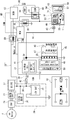
- FIG. 2 shows a power supply system configuration centering on a starter power supply.
- FIG.1 and FIG.2 the power supply system structure of FF plug-in hybrid vehicle is demonstrated.
- the power supply system includes a high power battery 21 as a motor / generator power supply, a 12V battery 22 (weak power battery) as a 12V system load power supply, and a capacitor 23 as a starter power supply. Yes.
- the high-power battery 21 is a secondary battery mounted as a power source for the motor / generator 4.
- a lithium ion battery in which a cell module in which a large number of cells are stacked is set in a battery pack case is used.
- the high-power battery 21 has a built-in junction box in which relay circuits for supplying / cutting off / distributing high-power are integrated, and further includes a battery temperature adjustment unit 24 having an air conditioner function, a battery charge capacity (battery SOC) and a battery. And a lithium battery controller 86 for monitoring the temperature.
- the high-power battery 21 and the motor / generator 4 are connected through a DC harness 25, an inverter 26, and an AC harness 27.
- the inverter 26 has a built-in junction box 28 in which relay circuits for supplying / cutting off / distributing strong power are integrated, and further includes a heating circuit 29, an electric air conditioner 30, and a motor controller 83 for performing power running / regenerative control. It is attached. That is, the inverter 26 converts a direct current from the DC harness 25 into a three-phase alternating current to the AC harness 27 during power running for driving the motor / generator 4 by discharging the high-power battery 21. Further, the three-phase alternating current from the AC harness 27 is converted into a direct current to the DC harness 25 during regeneration in which the high-power battery 21 is charged by power generation by the motor / generator 4.
- a fast charging port 32 is connected to the high-power battery 21 through a DC harness 31 and a normal charging port 35 is connected through a DC branch harness 25 ′, a charger 33, and an AC harness 34.
- the charger 33 performs AC / DC conversion and voltage conversion.
- a connector plug of a charging stand installed outside the office is connected to the quick charging port 32 to be externally charged (plug-in quick charging).
- a connector plug from a household power source is connected to the normal charging port 35 to be externally charged (plug-in normal charging).
- the 12V battery 22 is a secondary battery mounted as a power source for a 12V system load 36, which is another auxiliary machine except the starter motor 1, for example, a lead battery generally mounted in an engine vehicle or the like. Is used.
- the high voltage battery 21 and the 12V battery 22 are connected via a DC branch harness 25 ′′, a DC / DC converter 37, and a battery harness 38.
- the DC / DC converter 37 changes the voltage of several hundred volts from the high voltage battery 21 to 12V.
- the DC / DC converter 37 is controlled by the hybrid control module 81 to manage the charge amount of the 12V battery 22.
- the capacitor 23 is an electricity storage device mounted as a dedicated power source for the starter motor 1 and has a large capacitance and an electric double layer capacitor (eDLC: electric Double Layer Capacitor) having excellent rapid charge / discharge performance. What is called is used.
- eDLC electric Double Layer Capacitor
- the auxiliary load power supply system 39 and the capacitor 23 are connected via a battery branch harness 38 ′ provided with a fuse 40 and a capacitor charging circuit 41.
- the capacitor 23 and the starter motor 1 are connected via a capacitor harness 42, a resistor 43, and a relay switch 44.
- the capacitor 23 and the capacitor charging circuit 41 constitute a DLC unit 45
- the starter motor 1 and the relay switch 44 constitute a starter unit 46.
- detailed configurations of the DLC unit 45 and the starter unit 46 will be described.
- the DLC unit 45 includes a capacitor 23, a capacitor charging circuit 41, a spontaneous discharge switch 47, a forced discharge switch 48, a cell voltage monitor 49, and a capacitor temperature sensor 50. I have.
- the capacitor 23 is configured by connecting a plurality of DLC cells in series / parallel.
- the spontaneous discharge switch 47, the forced discharge switch 48, and the capacitor temperature sensor 50 are provided at both ends of the plurality of DLC cells.
- the capacitor charging circuit 41 is configured by a DC / DC converter circuit with a built-in semiconductor relay by a switching method, and includes a semiconductor relay 51 and a DC / DC converter 52 controlled by a hybrid control module 81.
- the semiconductor relay 51 is a non-contact relay using a semiconductor switching element, and is called, for example, a photocoupler that transmits an isolated input / output space with an optical signal as schematically shown in the lower left part of FIG.
- the configuration uses an optical semiconductor.
- the semiconductor relay 51 has a switch function for disconnecting or connecting the DLC unit 45 including the capacitor 23 from the auxiliary load power supply system 38.
- the DC / DC converter 52 is a combination circuit of a switching element 52a (a transistor, a MOS FET, etc.), a choke coil 52b, a capacitor 52c, and a diode 52d.
- a switching element 52a a transistor, a MOS FET, etc.
- the choke coil 52b stores energy by the current flowing from the input.
- the switching element 52a is OFF, the choke coil 52b releases the stored energy to maintain the current. Therefore, when the switching element 52a connected in parallel with the circuit is OFF, the energy from the choke coil 52b is “superimposed” on the input voltage, so that the output voltage is boosted (12V ⁇ 13.5V).
- This DC / DC converter circuit has a function of switching the capacitor charging current in addition to the DC conversion function.
- the starter unit 46 includes a starter motor 1, a relay switch 43, an electromagnetic actuator 53, and a pinion shift mechanism 54.
- the electromagnetic actuator 53 turns on the relay switch 44 and shifts the pinion 57 of the pinion shift mechanism 54 to a position where it meshes with the ring gear 58 by electromagnetic force generated by energization of the two coils 55 and 56.
- the relay switch 44 is turned off and the pinion 57 is shifted to a position where the engagement with the ring gear 58 is released.
- the ring gear 58 is provided on the crankshaft of the horizontal engine 2.
- the auxiliary load power supply system 39 and the two coils 55 and 56 are connected via a battery branch harness 38 ′′ provided with a starter cut-off relay 59, a HEV / IS / relay 60, and a starter relay 61.
- Energization / cutoff of the off relay 59 is performed by a body control module 87.
- Energization / cutoff of the HEV / IS / relay 60 is performed by a hybrid control module 81.
- Energization / cutoff of the starter relay 61 is performed by an underhood switching module.
- the voltage sensor 62 for relay diagnosis is provided at a position where the battery branch harness 38 "intersects.
- the pinion shift mechanism 54 has a pinion 57 provided so as to be movable in the axial direction with respect to the motor shaft of the starter motor 1, one end connected to the electromagnetic actuator 53, and the other end fitted into the shift groove of the pinion 57. Shift lever 63.
- Control system configuration 1 shows an overall system of an FF plug-in hybrid vehicle
- FIG. 2 shows a power supply system configuration centering on a starter power supply
- FIG. 3 shows a control system configuration.
- the control system configuration of the FF plug-in hybrid vehicle will be described with reference to FIGS.
- the control system includes a hybrid control module 81 (abbreviation: “HCM”) as an integrated control means for properly managing the energy consumption of the entire vehicle.
- Control means connected to the hybrid control module 81 include an engine control module 82 (abbreviation: “ECM”), a motor controller 83 (abbreviation: “MC”), and a CVT control unit 84 (abbreviation: “CVTCU”).
- ECM engine control module
- MC motor controller
- CVT control unit 84 abbreviation: “CVTCU”.
- the data communication module 85 abbreviation: “DCM”
- the lithium battery controller 86 abbreviation: “LBC”
- BCM body control module
- USB underhood switching module
- CAN communication lines 90 CAN is an abbreviation of “Controller Area Network” except for a LIN communication line 89 (LIN: abbreviation of “Local Interconnection Network”) that connects the hybrid control module 81 and the DLC unit 45. Is connected so that bidirectional information can be exchanged.
- LIN abbreviation of “Local Interconnection Network”
- the hybrid control module 81 performs various controls based on input information from each control means, an ignition switch 91, an accelerator opening sensor 92, a vehicle speed sensor 93, and the like. Among these, the control performed for the purpose of driving the FF plug-in hybrid vehicle capable of external charging with high fuel efficiency is a travel mode based on the battery SOC of the high-power battery 21 (“CD mode”, “CS mode”). Selection control.
- the “CD mode (Charge Depleting mode)” is a mode in which priority is given to EV running that consumes the power of the high-power battery 21 in principle. For example, while the battery SOC of the high-power battery 21 decreases from full SOC to set SOC. Is selected. However, HEV traveling is exceptionally performed in high-load traveling where driving force is insufficient in EV traveling.
- the start of the horizontal engine 2 during the selection of the “CD mode” is based on the start by the starter motor 1 (starter start), with the exception of the start by the motor / generator 4 (M / G start).
- the “CS mode (Charge Sustain mode)” is a mode in which priority is given to HEV traveling that maintains the power of the high-power battery 21 in principle, and is selected when the battery SOC of the high-power battery 21 is equal to or lower than the set SOC. That is, when it is necessary to maintain the battery SOC of the high-power battery 21 within a predetermined range, HEV traveling is performed by engine power generation that causes the motor / generator 4 to generate electric power by driving the lateral engine 2.
- the start of the horizontal engine 2 during the selection of the “CS mode” is based on the start by the motor / generator 4 (M / G start), with the exception of the start by the starter motor 1 (starter start).
- the “set SOC” that is the mode switching threshold value has hysteresis between the value when the CD mode ⁇ CS mode and the value when the CS mode ⁇ CD mode.
- the hybrid control module 81 performs engine start control by the starter motor 1, charge control to the capacitor 23, and discharge control from the capacitor 23 in addition to the selection control of “CD mode” and “CS mode”. Furthermore, the following starter start related control is performed.
- A Time-saving control from engine start to starter start permission.
- B Time shortening control from ignition on to starter start permission.
- C Deterioration progress suppression control of the capacitor 23.
- D Control of countermeasures for high / low temperature of capacitor 23.
- E Prevention of voltage sag of a vehicle auxiliary machine (Example 1).
- the engine control module 82 performs fuel injection control, ignition control, fuel cut control, and the like of the horizontally placed engine 2.
- the motor controller 83 performs power running control, regeneration control, and the like of the motor generator 4 by the inverter 26.
- the CVT control unit 84 performs engagement hydraulic pressure control of the first clutch 3, engagement hydraulic pressure control of the second clutch 5, shift hydraulic pressure control of the belt type continuously variable transmission 6, and the like.
- the data communication module 85 controls, for example, lock / unlock of the charging port lid and the connector lock mechanism.
- the lithium battery controller 86 manages the battery SOC, battery temperature, and the like of the high-power battery 21.
- the body control module 87 performs energization / cutoff control of the starter cut-off relay 59.
- the under hood switching module 87 performs energization / cut-off control of the built-in starter relay 61 based on the range position signal from the inhibitor switch 94.
- FIG. 5 shows a flow of capacitor power control processing executed by the hybrid control module 81 (capacitor power control means).
- the hybrid control module 81 capacitor power control means
- step S1 the capacity (DC / DC capacity: power supply amount) that can be charged from the high-power battery 21 to the 12V battery 22 and the capacitor 23 via the DC / DC converter 37 is the discharge capacity of the 12V battery 22 by the 12V system load 36. Then, it is determined whether or not it is larger than the capacity (required power amount) including the capacitor charge amount prepared for starter start. If Yes (DC / DC capacity> vehicle auxiliary machine + capacitor charge amount), the process proceeds to step S2. If No (DC / DC capacity ⁇ vehicle auxiliary machine + capacitor charge quantity), the process proceeds to step S3.
- step S2 following the determination that DC / DC capacity> vehicle auxiliary equipment + capacitor charge amount in step S1, the capacitor charging current is set to current 1 (for example, 15 A) or current 2 (for example, 7.5 A).
- the semiconductor relay 51 (capacitor switch circuit) included in the capacitor charging circuit 41 is closed, and the process proceeds to the end.
- the “threshold value a” is set as a limit value that does not reach the voltage drop (instantaneous drop) of the 12V system load 36 at the moment when the starter motor 1 starts the engine start.
- step S4 following the determination in step S3 that insufficient power ⁇ threshold value a, a command to change the capacitor charging current from current 1 (for example, 15A) to current 2 (for example, 7.5A) is given by the capacitor charging circuit. 41, and the process returns to step S1.
- current 1 for example, 15A
- current 2 for example, 7.5A
- step S5 following the determination that insufficient power ⁇ threshold value a in step S3, the semiconductor relay 51 (capacitor switch circuit) included in the capacitor charging circuit 41 is opened, and the auxiliary load power supply system 39 and the DLC unit 45 (starter A command to disconnect the load power source system) is output, and the process returns to step S1.
- the semiconductor relay 51 capacitor switch circuit included in the capacitor charging circuit 41 is opened, and the auxiliary load power supply system 39 and the DLC unit 45 (starter A command to disconnect the load power source system) is output, and the process returns to step S1.
- the functions of the control device for the FF plug-in hybrid vehicle of the first embodiment are as follows: [Characteristic action by the capacitor power supply circuit configuration], [Charge / discharge action by the capacitor power supply], [Effect of power supply amount from the high-power battery], [High-power battery] The power supply amount deficiency action from (power shortage ⁇ threshold a)] and [power supply deficiency action from high-power battery (insufficient power ⁇ threshold a)] will be described separately.
- the power supply circuit configuration is a configuration in which the DLC unit 45 and the fuse 40 are removed from the capacitor power supply circuit configuration of the first embodiment. To do.
- the power supply of the starter motor and the vehicle auxiliary machines is shared by one 12V battery. For this reason, if the starter motor is used to start the engine when the required amount of power in the vehicle auxiliaries is high, the supply power is insufficient, and the voltage of the vehicle auxiliaries decreases suddenly at the moment of starting the engine. Low occurs.
- the auxiliary load power supply system 39 is configured by connecting the high voltage battery 21 and the 12V battery 22 via the DC / DC converter 37.
- the DLC unit 45 includes a capacitor charging circuit 41 that is branched and connected from the DC / DC converter 37 and a capacitor 23 that is connected to the capacitor charging circuit 41.
- a capacitor power supply circuit is configured by providing a semiconductor relay 51 as a switch built in the capacitor charging circuit 41 between the auxiliary load power supply system 39 and the DLC unit 45.
- the 12V battery 22 and the capacitor 23 are charged with the electric power from the high-power battery 21, and the necessary power is supplied from the 12V battery 22 to the 12V system load 36, which is a vehicle auxiliary device.
- the starter motor 1 and the 12V system load 36 do not share the power source, and the two power sources including the 12V battery 22 and the capacitor 23 receive a charge backup by the high-power battery 21.
- the capacitor power supply circuit is configured by adding the DLC unit 45 (capacitor charging circuit 41 + capacitor 23) without changing the power supply circuit configuration of the idle stop vehicle which is the comparative example.
- the DLC unit 45 can be added in the same manner as the addition of auxiliary equipment, the control of the high-power battery 21 and the DC / DC converter 37 does not need to be changed from the control of the comparative example.
- the DLC unit 45 (capacitor charging circuit 41 + capacitor 23) can control the charging current and the auxiliary relay load by the semiconductor relay 51 as a switch.
- the power supply system 39 can be disconnected. That is, since the DLC unit 45 (capacitor charging circuit 41 + capacitor 23) is a unit electrically independent of the auxiliary load power supply system 39, the converter capacity of the DC / DC converter 37 and the battery capacity of the 12V battery 22 are There is no need to change the converter capacity or battery capacity set in the comparative example.
- the engine start by the starter motor 1 is based on the output of the starter start command from the hybrid control module 81.
- the relay switch 44 is turned on and the pinion 57 is shifted to a position where it engages with the ring gear 58. To do.
- the starter motor 1 using the capacitor 23 as a power source rotates the crankshaft of the horizontal engine 2 to start the starter, and the HEV / IS / relay 60 is cut off after a predetermined time from energization.
- the starter cut-off relay 59 is energized by the body control module 87 except when a vehicle condition prohibiting engine start is satisfied.
- the starter relay 61 built in the underhood switching module 88 is energized only when the P range is selected, and is in a cut-off state when a D range other than the P range is selected. Therefore, in principle, the engine start control by the starter motor 1 is performed by using the power of the capacitor 23 while the HEV / IS / relay 60 is energized by the starter start command under the starter start permission condition. Then, the horizontal engine 2 is started.
- the semiconductor relay 51 of the capacitor charging circuit 41 is closed based on the output of the charging command from the hybrid control module 81, and the capacitor charging current is selected.
- the electric power from the high-power battery 21 is introduced into the capacitor 23 through the DC / DC converter 37 ⁇ the fuse 40 ⁇ the semiconductor relay 51 ⁇ the DC / DC converter 52, so that the short-time charging according to the capacitor charging current can be performed.
- the capacitor charging current has a current 1 (for example, 15 A) as a basic current, and has a current 2 (for example, 7.5 A) that can be selected by changing from the current 1 as an exception. Therefore, the charging control to the capacitor 23 uses the power from the high-power battery 21 and charges the capacitor 23 with the selected capacitor charging current while the charging command is output.
- the discharge from the capacitor 23 causes the natural discharge from the capacitor 23 by closing the natural discharge switch 47 of the DLC unit 45. Further, the forced discharge from the capacitor 23 is performed by closing the forced discharge switch 48 of the DLC unit 45 based on the output of the forced discharge command from the hybrid control module 81.
- the discharge amount per unit time is set larger than that in the case of natural discharge. Therefore, the natural discharge control to the capacitor 23 is performed by converting the electric power of the capacitor 23 into resistance heat while the natural discharge switch 47 is closed based on the natural discharge command.
- the forced discharge control to the capacitor 23 while the forced discharge switch 48 is closed based on the forced discharge command, the power of the capacitor 23 is converted into resistance heat, and discharge is performed in a shorter time than natural discharge.
- step S1 ⁇ step S2 ⁇ end is repeated in the flowchart of FIG.
- step S1 when the discharge capacity taken out from the 12V battery 22 by the auxiliary load is low, such as when the light is turned off or the wiper is stopped in the daytime in fine weather, the DC that can charge the 12V battery 22 and the capacitor 23 via the DC / DC converter 37 / DC capacity (power supply) is sufficient.
- the power condition of step S1 is established and the process proceeds to step S2, where the capacitor charging current is set to current 1 (for example, 15 A) and the semiconductor relay 51 included in the capacitor charging circuit 41 is closed. Is done.
- the amount of power supplied via the DC / DC converter 37 is the sum of the discharge capacity of the 12V battery 22 by the 12V system load 36 and the amount of capacitor charge prepared for starter start. Exceeds the required amount. Therefore, under such conditions, even if the semiconductor relay 51 included in the capacitor charging circuit 41 is closed, the voltage drop of the vehicle auxiliary equipment does not occur due to the starter start intervention.
- the semiconductor relay 51 is used as a switch for opening and closing the connection between the auxiliary load power supply system 39 and the DLC unit 45 . That is, even if the semiconductor relay 51 using an optical semiconductor that transmits an isolated input / output space with an optical signal is closed and the auxiliary load power supply system 39 and the DLC unit 45 are connected, the insulating space of the semiconductor relay 51 Thus, the backflow from the capacitor 23 to the auxiliary load power supply system 39 is prevented. For this reason, when the engine is started by the starter motor 1, the electric power of the capacitor 23 is used only for driving the starter motor 1. In other words, the capacity reduction of the capacitor 23 due to the backflow of power from the capacitor 23 to the auxiliary load power supply system 39 is prevented, and it is possible to prepare for a restart request of the horizontally placed engine 2.
- the DC / DC converter 37 can charge the 12V battery 22 and the capacitor 23 through the DC / DC converter 37 when the discharge capacity taken out from the 12V battery 22 due to the auxiliary load is high due to light lighting, wiper operation, etc. at night. Insufficient DC capacity (power supply) relative to power requirements. In such a case, although the power condition in step S1 is not satisfied and the process proceeds to step S3, if the shortage power is less than the threshold value a, the shortage of power is reduced by controlling the capacitor charge amount. It is possible to suppress the occurrence of low. Therefore, the process proceeds from step S3 to step 4, and in step 4, a command to change the capacitor charging current from current 1 (for example, 15A) to current 2 (for example, 7.5A) is output to the capacitor charging circuit 41. .
- current 1 for example, 15A
- current 2 for example, 7.5A
- step S1 when traveling with a high discharge capacity due to the auxiliary load, the amount of power supplied via the DC / DC converter 37 is obtained by adding the discharge capacity of the 12V battery 22 by the 12V system load 36 and the charge amount of the capacitor for starting the starter.
- the power condition of step S1 is established by changing the capacitor charging current to current 2 ( ⁇ current 1). That is, after changing the capacitor charging current to the current 2, in the flowchart of FIG. 5, the process proceeds from step S1 to step S2, and in step S2, the capacitor charging current is set to the current 2 (for example, 7.5A).
- the semiconductor relay 51 included in 41 is closed.
- the starter start intervention is performed even if the semiconductor relay 51 included in the capacitor charging circuit 41 is closed by changing the capacitor charging current to the current 2 ( ⁇ current 1). This prevents the voltage drop of the vehicle auxiliary machinery from occurring.
- the 12V battery 22 and the capacitor 23 are charged via the DC / DC converter 37 when driving at a high discharge capacity taken from the 12V battery 22 due to the load of the auxiliary equipment, such as lighting at night, wiper operation, electric power steering operation, etc.
- auxiliary equipment such as lighting at night, wiper operation, electric power steering operation, etc.
- DC / DC capacity power supply
- the process proceeds from step S3 to step 5.
- step 5 the semiconductor relay 51 included in the capacitor charging circuit 41 is opened, and a command to disconnect the auxiliary load power supply system 39 and the DLC unit 45 is output to the capacitor charging circuit 41. .
- the amount of power supplied via the DC / DC converter 37 is the sum of the discharge capacity of the 12V battery 22 by the 12V system load 36 and the amount of capacitor charge prepared for starter start. Below the required amount.
- the semiconductor relay 51 is opened, and the auxiliary load power supply system 39 and the DLC unit 45 are disconnected. That is, when starting the starter, the DLC unit 45 is electrically independent of the auxiliary load power supply system 39.
- the power supplied to the auxiliary load power supply system 39 that is electrically independent from the DLC unit 45 is It is maintained as it is, and it is possible to prevent the voltage of the 12V system load 36 which is a vehicle auxiliary machine from suddenly decreasing.
- a configuration is employed in which a fuse 40 is provided between the DC / DC converter 37 and the capacitor charging circuit 42 to shut off the circuit when an excessive current flows in a fixed failure state with the semiconductor relay 51 closed. did.
- the fuse 40 is blown to cut off the circuit, The auxiliary load power supply system 39 and the DLC unit 45 are disconnected. Therefore, even when the semiconductor relay 51 is stuck, it is guaranteed that the voltage of the 12V system load 36, which is a vehicle auxiliary device, suddenly decreases when the starter is started.
- the drive system has a starter motor 1, an engine (horizontal engine 2), and a motor / generator 4.
- a high-power battery 21 as a power source of the motor / generator 4
- a low-power battery (12V battery 22) as a power source of vehicle auxiliary machines
- a capacitor 23 as a power source of the starter motor 1, and the capacitor 23
- a control device for a hybrid vehicle comprising capacitor power source control means (hybrid control module 81) for controlling charging and discharging of
- An auxiliary load power supply system 39 is configured by connecting the high-power battery 21 and the low-power battery (12V battery 22) via a DC / DC converter 37
- a starter load power supply system (DLC unit 45) having a capacitor charging circuit 41 controlled by the capacitor 23 and the capacitor power supply control means (hybrid control module 81) is connected to a DC of the auxiliary load power supply system 39.
- a capacitor power supply circuit can be configured only by adding the capacitor 23 and the capacitor charging circuit 41 to the existing circuit without changing the control / capacity of the high-power battery 21 and the auxiliary load power supply system 39.
- a switch is provided between the auxiliary load power supply system 39 and the starter load power supply system (DLC unit 45),
- the capacitor power control means (hybrid control module 81) opens the switch (semiconductor relay 51) when the engine is started by the starter motor 1, and opens the auxiliary load power system 39 and the starter load power system (DLC unit 45). (Fig. 5). For this reason, in addition to the effect of (1), when the engine is started by the starter motor 1, it is possible to prevent a voltage drop of the vehicle auxiliary machinery.
- the capacitor power control means has a power supply amount that can be supplied from the high-power battery 21 to the low-power battery (12V battery 22) and the capacitor 23 via the DC / DC converter 37.
- the switch semiconductor relay 51
- the auxiliary load power supply system 39 and the starter load power supply system DLC unit 45
- the voltage drop due to the starter start can be surely prevented by opening the switch (semiconductor relay 51) in advance.
- the capacitor power supply control means includes: a power supply amount that can be supplied to the low-power battery (12V battery 22) and the capacitor 23; and a power requirement amount by an auxiliary load and a starter load.
- a power supply amount that can be supplied to the low-power battery (12V battery 22) and the capacitor 23
- a power requirement amount by an auxiliary load and a starter load.
- the capacitor power supply control means includes: a power supply amount that can be supplied to the low-power battery (12V battery 22) and the capacitor 23; and a power requirement amount by an auxiliary load and a starter load.
- the switch semiconductor relay 51
- the auxiliary load power supply system 39 and the starter load power supply system DLC unit 45
- the voltage drop due to starter start can be reliably reduced by opening the switch (semiconductor relay 51) in advance. Can be prevented.
- the starter load power supply system includes a backflow prevention circuit (semiconductor relay 51) from the capacitor 23 to the auxiliary load power supply system 39 when connected to the auxiliary load power supply system 39. (FIG. 2). For this reason, in addition to the effects (1) to (5), the capacity reduction of the capacitor 23 due to the backflow of power from the capacitor 23 to the auxiliary load power supply system 39 is prevented, and the horizontal engine 2 is restarted by the starter motor 1. Can prepare for the request.
- the backflow prevention circuit is configured by using, as the switch, a semiconductor relay 51 using an optical semiconductor that transmits an isolated input / output space by an optical signal (FIG. 2). For this reason, in addition to the effect of (6), by using the semiconductor relay 51 having a switch function and a backflow prevention function, a backflow prevention circuit can be formed with a simple configuration that does not require an additional circuit.
- a fuse 40 is provided between the DC / DC converter 37 and the capacitor charging circuit 41 to cut off the circuit when an excessive current flows in a stuck failure state with the switch (semiconductor relay 51) closed. (FIG. 2). For this reason, in addition to the effects of (1) to (7), against the switch (semiconductor relay 51) fixing failure, it is guaranteed that the voltage of the vehicle auxiliary machinery suddenly drops when the starter is started. can do.
- the hybrid vehicle control device of the present invention has been described based on the first embodiment. However, the specific configuration is not limited to the first embodiment, and the invention according to each claim of the claims is described. Design changes and additions are allowed without departing from the gist.
- the capacitor power control means when the insufficient power is less than the threshold value a, the charging current to the capacitor 23 is reduced (current 1 ⁇ current 2).
- An example is shown in which the auxiliary load power supply system 39 and the DLC unit 45 are disconnected.
- the capacitor power supply control means when the power supply amount that can be supplied from the high power battery to the low power battery and the capacitor is insufficient with respect to the power requirement by the auxiliary load and the starter load, regardless of the magnitude of the power shortage, It is also possible to open the switch and disconnect the auxiliary load power system from the starter load power system.
- the capacitor power control means when the power supply that can be supplied from the high-power battery to the low-power battery and the capacitor is insufficient with respect to the power required by the auxiliary load and the starter load, the switch is opened to An example of preventing the voltage drop of a kind was shown.
- the capacitor power supply control means is not limited to whether or not there is insufficient power generation.When the engine is started by the starter motor, the switch is opened based on the starter start command and the auxiliary load power supply system and the starter load power supply system are separated. good.
- the hybrid control module 81 is used as the capacitor power source control means.
- the capacitor power supply control means an independently provided power supply system controller may be used, or an example in which a power supply system control unit is provided in a controller other than the hybrid control module may be used.
- the semiconductor relay 51 is used as a switch built in the capacitor charging circuit 41 provided between the auxiliary load power supply system 39 and the capacitor 23 .
- the switch is not limited to a semiconductor relay, and other switches such as an electromagnetic relay may be used, and may be provided independently from the capacitor charging circuit.
- a non-contact switch such as a semiconductor relay is not used as a switch, a backflow prevention circuit using a diode or the like is set separately from the switch.
- Example 1 shows an example in which the control device of the present invention is applied to an FF plug-in hybrid vehicle.
- the control device of the present invention can also be applied to a hybrid vehicle that does not have an external charging function.
- the present invention can be applied not only to FF hybrid vehicles but also to FR hybrid vehicles and 4WD hybrid vehicles.
- the present invention can be applied to any hybrid vehicle including a high-power battery that is a motor / generator power source, a low-power battery that is a vehicle auxiliary power source, and a capacitor that is a starter motor power source for starting an engine.
Abstract
Description
このハイブリッド車両の制御装置において、
前記強電バッテリと前記弱電バッテリを、DC/DCコンバータを介して接続することで補機負荷電源系を構成し、前記キャパシタと前記キャパシタ電源制御手段により制御されるキャパシタ充電回路を有して構成されるスタータ負荷電源系を、前記補機負荷電源系のDC/DCコンバータから分岐して接続した。
すなわち、キャパシタとキャパシタ充電回路を有して構成されるスタータ負荷電源系が、強電バッテリ及び補機負荷電源系から電気的に独立したものとなる。このため、強電バッテリとDC/DCコンバータの制御は、スタータ負荷電源系を追加する前の制御から変更する必要がない。そして、DC/DCコンバータのコンバータ容量や弱電バッテリのバッテリ容量を、スタータ負荷電源系を追加する前に設定したコンバータ容量やバッテリ容量から変更する必要がない。
この結果、強電バッテリと補機負荷電源系の制御/容量を変更することなく、既存回路にキャパシタとキャパシタ充電回路を追加するだけでキャパシタ電源回路を構成することができる。
実施例1の制御装置が適用されたFFプラグインハイブリッド車両(ハイブリッド車両の一例)の構成を、「駆動システム構成」、「電源システム構成」、「制御システム構成」、「キャパシタ電源制御の詳細構成」に分けて説明する。
図1はFFプラグインハイブリッド車両の全体を示す。以下、図1に基づいて、FFプラグインハイブリッド車両の駆動システム構成を説明する。
図1はFFプラグインハイブリッド車両の全体システムを示し、図2はスタータ電源を中心とする電源システム構成を示す。以下、図1及び図2に基づいて、FFプラグインハイブリッド車両の電源システム構成を説明する。
図1はFFプラグインハイブリッド車両の全体システムを示し、図2はスタータ電源を中心とする電源システム構成を示し、図3は制御システム構成を示す。以下、図1~図3に基づいて、FFプラグインハイブリッド車両の制御システム構成を説明する。
(A)エンジン始動後からスタータ始動許可までの時間短縮制御。
(B)イグニッションオンからスタータ始動許可までの時間短縮制御。
(C)キャパシタ23の劣化進行抑制制御。
(D)キャパシタ23の高温/低温時対策制御。
(E)車両用補機の電圧瞬低防止制御(実施例1)。
図5はハイブリッドコントロールモジュール81にて実行されるキャパシタ電源制御処理流れを示す(キャパシタ電源制御手段)。以下、キャパシタ電源制御処理構成をあらわす図5の各ステップについて説明する。
ここで、「閾値a」は、スタータモータ1によりエンジン始動を開始した瞬間、12V系負荷36の電圧低下(瞬低)までに至らない限界値として設定される。
実施例1のFFプラグインハイブリッド車両の制御装置における作用を、[キャパシタ電源回路構成による特徴作用]、[キャパシタ電源による充放電作用]、[強電バッテリからの電力供給量充足作用]、[強電バッテリからの電力供給量不足作用(不足電力<閾値a)]、[強電バッテリからの電力供給量不足作用(不足電力≧閾値a)]に分けて説明する。
例えば、アイドルストップ車において、スタータモータの電源を12Vバッテリとする場合、電源回路構成は、実施例1のキャパシタ電源回路構成からDLCユニット45とヒューズ40を除いた構成とされ、これを比較例とする。
上記キャパシタ電源回路に対しハイブリッドコントロールモジュール81により行われる「スタータモータ1によるエンジン始動制御作用」、「キャパシタ23への充電制御作用」、「キャパシタ23からの放電制御作用」を説明する。
したがって、スタータモータ1によるエンジン始動制御は、原則として、スタータ始動許可条件下でのスタータ始動指令によりHEV/IS/リレー60が通電されている間、キャパシタ23の電力を用いてスタータモータ1が駆動し、横置きエンジン2を始動させる。
したがって、キャパシタ23への充電制御は、充電指令が出力されている間、強電バッテリ21からの電力を用い、選択されているキャパシタ充電電流によりキャパシタ23を充電する。
したがって、キャパシタ23への自然放電制御は、自然放電指令に基づいて自然放電用スイッチ47を閉としている間、キャパシタ23の電力を抵抗熱に変換して放電を行う。キャパシタ23への強制放電制御は、強制放電指令に基づいて強制放電用スイッチ48を閉としている間、キャパシタ23の電力を抵抗熱に変換し、自然放電よりも短時間にて放電を行う。
強電バッテリ21からの電力供給量が充足している場合、車両補機類の作動中にスタータ始動が介入しても車両補機類の電圧瞬低が発生することがない。以下、図5に基づき、これを反映する強電バッテリ21からの電力供給量充足作用を説明する。
すなわち、絶縁された入出力の空間を光の信号で伝達する光半導体を用いた半導体リレー51を閉とし、補機負荷電源系39とDLCユニット45を接続しても、半導体リレー51の絶縁空間により、キャパシタ23から補機負荷電源系39への逆流が防止される。
このため、スタータモータ1によるエンジン始動時、キャパシタ23の電力がスタータモータ1の駆動にのみ用いられる。言い換えると、キャパシタ23から補機負荷電源系39への電力の逆流によるキャパシタ23の容量低下が防止され、横置きエンジン2の再始動要求に備えることができる。
以下、図5に基づき、強電バッテリ21からの電力供給量不足作用(不足電力<閾値a)を説明する。
以下、図5に基づき、強電バッテリ21からの電力供給量不足作用(不足電力≧閾値a)を説明する。
この構成により、半導体リレー51が閉じた状態のままとなるリレーの固着故障時、補機負荷にスタータ負荷が加わることで過大電流が流れると、ヒューズ40が切れることにより回路を遮断することで、補機負荷電源系39とDLCユニット45が切り離される。
したがって、半導体リレー51の固着故障に対しても、スタータ始動時、車両補機類である12V系負荷36の電圧が急に低下する電圧瞬低の防止が保証される。
実施例1のFFプラグインハイブリッド車両の制御装置にあっては、下記に列挙する効果を得ることができる。
電源システムとして、前記モータ/ジェネレータ4の電源である強電バッテリ21と、車両補機類の電源である弱電バッテリ(12Vバッテリ22)と、前記スタータモータ1の電源であるキャパシタ23と、前記キャパシタ23の充放電を制御するキャパシタ電源制御手段(ハイブリッドコントロールモジュール81)と、を備えたハイブリッド車両(FFプラグインハイブリッド車両)の制御装置において、
前記強電バッテリ21と前記弱電バッテリ(12Vバッテリ22)を、DC/DCコンバータ37を介して接続することで補機負荷電源系39を構成し、
前記キャパシタ23と前記キャパシタ電源制御手段(ハイブリッドコントロールモジュール81)により制御されるキャパシタ充電回路41を有して構成されるスタータ負荷電源系(DLCユニット45)を、前記補機負荷電源系39のDC/DCコンバータ37から分岐して接続した(図2)。
このため、強電バッテリ21と補機負荷電源系39の制御/容量を変更することなく、既存回路にキャパシタ23とキャパシタ充電回路41を追加するだけでキャパシタ電源回路を構成することができる。
前記キャパシタ電源制御手段(ハイブリッドコントロールモジュール81)は、前記スタータモータ1によるエンジン始動時、前記スイッチ(半導体リレー51)を開き、前記補機負荷電源系39と前記スタータ負荷電源系(DLCユニット45)を切り離す(図5)。
このため、(1)の効果に加え、スタータモータ1によるエンジン始動時、車両補機類の電圧瞬低を防止することができる。
このため、(2)の効果に加え、不足電力発生条件が成立すると、予めスイッチ(半導体リレー51)を開いておくことで、確実にスタータ始動による電圧瞬低を防止することができる。
このため、(3)の効果に加え、不足電力発生条件が成立していても不足電力が小さいときに限っては、不足電力を解消するキャパシタ充電電流の低下制御を行うことで、スイッチ(半導体リレー51)を閉じたままでも、スタータ始動による電圧瞬低を防止することができる。
このため、(4)の効果に加え、不足電力が大きくキャパシタ充電電流制御によって不足電力を解消できないとき、予めスイッチ(半導体リレー51)を開いておくことで、確実にスタータ始動による電圧瞬低を防止することができる。
このため、(1)~(5)の効果に加え、キャパシタ23から補機負荷電源系39への電力の逆流によるキャパシタ23の容量低下が防止され、スタータモータ1による横置きエンジン2の再始動要求に備えることができる。
このため、(6)の効果に加え、スイッチ機能と逆流防止機能を持つ半導体リレー51を用いることで、追加回路を要さない簡単な構成にて逆流防止回路にすることができる。
このため、(1)~(7)の効果に加え、スイッチ(半導体リレー51)の固着故障に対して、スタータ始動時、車両補機類の電圧が急に低下する電圧瞬低の防止を保証することができる。
Claims (8)
- 駆動系にスタータモータとエンジンとモータ/ジェネレータを有し、
電源システムとして、前記モータ/ジェネレータの電源である強電バッテリと、車両補機類の電源である弱電バッテリと、前記スタータモータの電源であるキャパシタと、前記キャパシタの充放電を制御するキャパシタ電源制御手段と、を備えたハイブリッド車両の制御装置において、
前記強電バッテリと前記弱電バッテリを、DC/DCコンバータを介して接続することで補機負荷電源系を構成し、
前記キャパシタと前記キャパシタ電源制御手段により制御されるキャパシタ充電回路を有して構成されるスタータ負荷電源系を、前記補機負荷電源系のDC/DCコンバータから分岐して接続した
ことを特徴とするハイブリッド車両の制御装置。 - 請求項1に記載されたハイブリッド車両の制御装置において、
前記補機負荷電源系と前記スタータ負荷電源系との間にスイッチを設け、
前記キャパシタ電源制御手段は、前記スタータモータによるエンジン始動時、前記スイッチを開き、前記補機負荷電源系と前記スタータ負荷電源系を切り離す
ことを特徴とするハイブリッド車両の制御装置。 - 請求項2に記載されたハイブリッド車両の制御装置において、
前記キャパシタ電源制御手段は、前記強電バッテリから前記DC/DCコンバータを介して前記弱電バッテリと前記キャパシタへ供給可能な電力供給量が、補機負荷とスタータ負荷による電力必要量に対し不足するとき、前記スイッチを開き、前記補機負荷電源系と前記スタータ負荷電源系を切り離す
ことを特徴とするハイブリッド車両の制御装置。 - 請求項3に記載されたハイブリッド車両の制御装置において、
前記キャパシタ電源制御手段は、前記弱電バッテリと前記キャパシタへ供給可能な電力供給量と、補機負荷とスタータ負荷による電力必要量と、の差による不足電力が閾値未満のとき、前記キャパシタへの充電電流を低下させる
ことを特徴とするハイブリッド車両の制御装置。 - 請求項4に記載されたハイブリッド車両の制御装置において、
前記キャパシタ電源制御手段は、前記弱電バッテリと前記キャパシタへ供給可能な電力供給量と、補機負荷とスタータ負荷による電力必要量と、の差による不足電力が閾値以上のとき、前記スイッチを開き、前記補機負荷電源系と前記スタータ負荷電源系を切り離す
ことを特徴とするハイブリッド車両の制御装置。 - 請求項1から5までの何れか一項に記載されたハイブリッド車両の制御装置において、
前記スタータ負荷電源系は、前記補機負荷電源系と接続状態のとき、前記キャパシタから前記補機負荷電源系への逆流防止回路を有する
ことを特徴とするハイブリッド車両の制御装置。 - 請求項6に記載されたハイブリッド車両の制御装置において、
前記逆流防止回路は、前記スイッチとして、絶縁された入出力の空間を光の信号で伝達する光半導体を用いた半導体リレーを用いることにより構成した
ことを特徴とするハイブリッド車両の制御装置。 - 請求項1から7までの何れか一項に記載されたハイブリッド車両の制御装置において、
前記DC/DCコンバータと前記キャパシタ充電回路の間に、前記スイッチが閉じたままの固着故障状態で過大電流が流れることにより回路を遮断するヒューズを設けた
ことを特徴とするハイブリッド車両の制御装置。
Priority Applications (4)
| Application Number | Priority Date | Filing Date | Title |
|---|---|---|---|
| CN201480032480.8A CN105283335A (zh) | 2013-06-07 | 2014-03-26 | 混合动力车辆的控制装置 |
| JP2015521321A JPWO2014196242A1 (ja) | 2013-06-07 | 2014-03-26 | ハイブリッド車両の制御装置 |
| US14/889,219 US20160089981A1 (en) | 2013-06-07 | 2014-03-26 | Control system for a hybrid vehicle |
| EP14807501.3A EP3006244A4 (en) | 2013-06-07 | 2014-03-26 | HYBRID VEHICLE CONTROL DEVICE |
Applications Claiming Priority (2)
| Application Number | Priority Date | Filing Date | Title |
|---|---|---|---|
| JP2013-120687 | 2013-06-07 | ||
| JP2013120687 | 2013-06-07 |
Publications (1)
| Publication Number | Publication Date |
|---|---|
| WO2014196242A1 true WO2014196242A1 (ja) | 2014-12-11 |
Family
ID=52007898
Family Applications (1)
| Application Number | Title | Priority Date | Filing Date |
|---|---|---|---|
| PCT/JP2014/058476 WO2014196242A1 (ja) | 2013-06-07 | 2014-03-26 | ハイブリッド車両の制御装置 |
Country Status (5)
| Country | Link |
|---|---|
| US (1) | US20160089981A1 (ja) |
| EP (1) | EP3006244A4 (ja) |
| JP (1) | JPWO2014196242A1 (ja) |
| CN (1) | CN105283335A (ja) |
| WO (1) | WO2014196242A1 (ja) |
Cited By (2)
| Publication number | Priority date | Publication date | Assignee | Title |
|---|---|---|---|---|
| CN105365596A (zh) * | 2015-11-26 | 2016-03-02 | 上海循道新能源科技有限公司 | 一种用于电动汽车交流充电桩的智能控制系统 |
| CN109747420A (zh) * | 2017-11-08 | 2019-05-14 | 丰田自动车株式会社 | 车辆用电源系统 |
Families Citing this family (40)
| Publication number | Priority date | Publication date | Assignee | Title |
|---|---|---|---|---|
| JP6172273B2 (ja) * | 2013-05-29 | 2017-08-02 | 日産自動車株式会社 | プラグインハイブリッド車両の制御装置 |
| DE102013013954A1 (de) * | 2013-08-21 | 2015-02-26 | Audi Ag | Antriebsvorrichtung für ein Hybridfahrzeug |
| DE102015201032B4 (de) * | 2015-01-22 | 2018-12-20 | Volkswagen Aktiengesellschaft | Lenksystem für ein automatisiertes Fahren eines Kraftfahrzeuges |
| JP6146435B2 (ja) * | 2015-04-23 | 2017-06-14 | トヨタ自動車株式会社 | 車両 |
| CN106114226B (zh) * | 2016-08-30 | 2018-01-12 | 中车株洲电力机车有限公司 | 一种动车组前端结构及救援连接方法 |
| CN106347156B (zh) * | 2016-09-18 | 2018-08-28 | 深圳市科列技术股份有限公司 | 一种车载充电控制管理模块、系统和方法 |
| US10087903B2 (en) * | 2017-01-13 | 2018-10-02 | Ford Global Technologies, Llc | Vehicle energy management |
| KR20180094327A (ko) * | 2017-02-15 | 2018-08-23 | 주식회사 만도 | 전동식 조향 장치의 모터 제어 장치 및 모터 제어 방법 |
| CN106870237A (zh) * | 2017-03-22 | 2017-06-20 | 上汽通用汽车有限公司 | 车辆的发动机的起动方法和装置 |
| JP6541713B2 (ja) * | 2017-04-28 | 2019-07-10 | 本田技研工業株式会社 | 車両の電源装置 |
| EP3425766B1 (en) * | 2017-07-03 | 2022-08-24 | Ningbo Geely Automobile Research & Development Co., Ltd. | A capacitor module |
| JP2019118240A (ja) * | 2017-12-27 | 2019-07-18 | 日本電産トーソク株式会社 | 車両用駆動装置 |
| DE102018110621A1 (de) * | 2018-05-03 | 2019-11-07 | Innofas Gmbh | Hochgeschwindigkeitsentladesystem für einen Hochspannungsenergiespeicher |
| JP7020293B2 (ja) * | 2018-05-25 | 2022-02-16 | トヨタ自動車株式会社 | バッテリ放電制御装置 |
| JP7103127B2 (ja) * | 2018-09-28 | 2022-07-20 | トヨタ自動車株式会社 | 車載制御装置及び車両 |
| JP7124619B2 (ja) * | 2018-10-04 | 2022-08-24 | トヨタ自動車株式会社 | エンジンの始動装置およびエンジンの始動方法 |
| IT201800009968A1 (it) * | 2018-10-31 | 2020-05-01 | Piaggio & C Spa | Dispositivo di alimentazione e controllo di un veicolo elettrico |
| CN109291868B (zh) * | 2018-11-27 | 2020-10-09 | 安徽江淮汽车集团股份有限公司 | 一种混合动力车型发电控制方法及系统 |
| JP7332287B2 (ja) * | 2018-12-26 | 2023-08-23 | 株式会社Subaru | 車載電気システム |
| CN109552084A (zh) * | 2018-12-30 | 2019-04-02 | 宁波中车新能源科技有限公司 | 一种混合动力电车启停系统及其控制方法 |
| JP7222737B2 (ja) * | 2019-02-05 | 2023-02-15 | 株式会社Subaru | 車両 |
| JP7230635B2 (ja) * | 2019-03-27 | 2023-03-01 | トヨタ自動車株式会社 | 電力システムおよびその制御方法 |
| US11289974B2 (en) | 2019-06-07 | 2022-03-29 | Anthony Macaluso | Power generation from vehicle wheel rotation |
| US11837411B2 (en) | 2021-03-22 | 2023-12-05 | Anthony Macaluso | Hypercapacitor switch for controlling energy flow between energy storage devices |
| US11615923B2 (en) | 2019-06-07 | 2023-03-28 | Anthony Macaluso | Methods, systems and apparatus for powering a vehicle |
| US11685276B2 (en) | 2019-06-07 | 2023-06-27 | Anthony Macaluso | Methods and apparatus for powering a vehicle |
| US11432123B2 (en) | 2019-06-07 | 2022-08-30 | Anthony Macaluso | Systems and methods for managing a vehicle's energy via a wireless network |
| US11641572B2 (en) | 2019-06-07 | 2023-05-02 | Anthony Macaluso | Systems and methods for managing a vehicle's energy via a wireless network |
| DE102019220536A1 (de) * | 2019-12-23 | 2021-06-24 | Robert Bosch Gesellschaft mit beschränkter Haftung | Verfahren, Computerprogramm, elektronisches Speichermedium und Vorrichtung zur Erkennung des Abrisses einer Energiereserveeinrichtung |
| CN111098846A (zh) * | 2020-01-08 | 2020-05-05 | 中国第一汽车股份有限公司 | 一种车用混合动力电气系统及汽车 |
| US11230203B2 (en) * | 2020-01-30 | 2022-01-25 | Ford Global Technologies, Llc | Selective illumination of charging port status indicators for an electrified vehicle |
| WO2021199154A1 (ja) * | 2020-03-30 | 2021-10-07 | 日立建機株式会社 | 建設機械 |
| CN111661030B (zh) * | 2020-06-10 | 2021-10-08 | 中国第一汽车股份有限公司 | 混合动力车辆的起动机控制方法、系统及混合动力车辆 |
| CN114200336B (zh) * | 2020-08-27 | 2023-11-14 | 广州汽车集团股份有限公司 | 一种电动转向系统电源故障诊断方法、电路、电动转向系统及汽车 |
| CN113561800B (zh) * | 2020-09-29 | 2024-04-02 | 株式会社电装 | 带升压四驱系统的控制方法 |
| CN112436768B (zh) * | 2020-11-12 | 2022-09-09 | 漳州科华技术有限责任公司 | 一种车载变换器的控制方法、系统、装置及车载变换器 |
| WO2022203743A1 (en) * | 2021-03-22 | 2022-09-29 | Anthony Macaluso | Hypercapacitor apparatus for storing and providing energy |
| US11577606B1 (en) | 2022-03-09 | 2023-02-14 | Anthony Macaluso | Flexible arm generator |
| US11472306B1 (en) | 2022-03-09 | 2022-10-18 | Anthony Macaluso | Electric vehicle charging station |
| US11955875B1 (en) | 2023-02-28 | 2024-04-09 | Anthony Macaluso | Vehicle energy generation system |
Citations (4)
| Publication number | Priority date | Publication date | Assignee | Title |
|---|---|---|---|---|
| JPH05328530A (ja) * | 1992-03-16 | 1993-12-10 | Toyota Motor Corp | ハイブリッド車用電源装置 |
| JP2006002626A (ja) * | 2004-06-16 | 2006-01-05 | Mitsubishi Motors Corp | 車両用電源装置 |
| JP2012167627A (ja) | 2011-02-16 | 2012-09-06 | Nissan Motor Co Ltd | エンジンの始動装置 |
| WO2013080746A1 (ja) * | 2011-11-29 | 2013-06-06 | 日立オートモティブシステムズ株式会社 | エンジン始動装置および始動方法 |
Family Cites Families (17)
| Publication number | Priority date | Publication date | Assignee | Title |
|---|---|---|---|---|
| US5285862A (en) * | 1992-03-16 | 1994-02-15 | Toyota Jidosha Kabushiki Kaisha | Power supply system for hybrid vehicles |
| JPH08240171A (ja) * | 1995-02-28 | 1996-09-17 | Sawafuji Electric Co Ltd | 車両エンジン始動用電源装置 |
| US6325035B1 (en) * | 1999-09-30 | 2001-12-04 | Caterpillar Inc. | Method and apparatus for starting an engine using capacitor supplied voltage |
| JP4797488B2 (ja) * | 2005-07-26 | 2011-10-19 | パナソニック株式会社 | 車両用電源装置 |
| JP4867619B2 (ja) * | 2006-07-10 | 2012-02-01 | パナソニック株式会社 | 電源装置 |
| DE102007062955B4 (de) * | 2007-12-21 | 2011-06-01 | Catem Develec Gmbh & Co. Kg | Schaltung zur Spannungsstabilisierung eines Bordnetzes |
| FR2933357B1 (fr) * | 2008-07-02 | 2011-02-11 | Peugeot Citroen Automobiles Sa | Systeme de gestion electrique multi tension pour vehicule hybride. |
| JP4636199B2 (ja) * | 2008-10-04 | 2011-02-23 | 株式会社デンソー | エンジン自動停止始動制御装置 |
| US8020650B2 (en) * | 2009-03-19 | 2011-09-20 | GM Global Technology Operations LLC | Control of a starter-alternator during a high-voltage battery fault condition |
| JP4862074B2 (ja) * | 2009-09-30 | 2012-01-25 | 三菱電機株式会社 | エンジンの始動方法 |
| CN201854093U (zh) * | 2010-01-21 | 2011-06-01 | 孙晓林 | 一种多功能汽车启动供电装置 |
| US9168837B2 (en) * | 2010-05-12 | 2015-10-27 | Toyota Jidosha Kabushiki Kaisha | Vehicle and method of controlling vehicle |
| WO2012074531A1 (en) * | 2010-12-03 | 2012-06-07 | International Truck Intellectual Property Company, Llc | Battery management system for restricted idle vehicles |
| FR2977530A1 (fr) * | 2011-07-05 | 2013-01-11 | Peugeot Citroen Automobiles Sa | Dispositif d'alimentation electrique d'un vehicule automobile hybride |
| US20140176085A1 (en) * | 2011-09-07 | 2014-06-26 | Honda Motor Co., Ltd. | Battery controller of vehicle |
| JP5865013B2 (ja) * | 2011-10-27 | 2016-02-17 | 三洋電機株式会社 | 車両用の電源装置及びこの電源装置を備える車両 |
| US9744960B2 (en) * | 2013-05-29 | 2017-08-29 | Nissan Motor Co., Ltd. | Control system for a plug-in hybrid vehicle |
-
2014
- 2014-03-26 CN CN201480032480.8A patent/CN105283335A/zh active Pending
- 2014-03-26 JP JP2015521321A patent/JPWO2014196242A1/ja active Pending
- 2014-03-26 US US14/889,219 patent/US20160089981A1/en not_active Abandoned
- 2014-03-26 WO PCT/JP2014/058476 patent/WO2014196242A1/ja active Application Filing
- 2014-03-26 EP EP14807501.3A patent/EP3006244A4/en not_active Withdrawn
Patent Citations (4)
| Publication number | Priority date | Publication date | Assignee | Title |
|---|---|---|---|---|
| JPH05328530A (ja) * | 1992-03-16 | 1993-12-10 | Toyota Motor Corp | ハイブリッド車用電源装置 |
| JP2006002626A (ja) * | 2004-06-16 | 2006-01-05 | Mitsubishi Motors Corp | 車両用電源装置 |
| JP2012167627A (ja) | 2011-02-16 | 2012-09-06 | Nissan Motor Co Ltd | エンジンの始動装置 |
| WO2013080746A1 (ja) * | 2011-11-29 | 2013-06-06 | 日立オートモティブシステムズ株式会社 | エンジン始動装置および始動方法 |
Non-Patent Citations (1)
| Title |
|---|
| See also references of EP3006244A4 |
Cited By (5)
| Publication number | Priority date | Publication date | Assignee | Title |
|---|---|---|---|---|
| CN105365596A (zh) * | 2015-11-26 | 2016-03-02 | 上海循道新能源科技有限公司 | 一种用于电动汽车交流充电桩的智能控制系统 |
| CN105365596B (zh) * | 2015-11-26 | 2018-04-24 | 上海循道新能源科技有限公司 | 一种用于电动汽车交流充电桩的智能控制系统 |
| CN109747420A (zh) * | 2017-11-08 | 2019-05-14 | 丰田自动车株式会社 | 车辆用电源系统 |
| JP2019088141A (ja) * | 2017-11-08 | 2019-06-06 | トヨタ自動車株式会社 | 車両用電源システム |
| CN109747420B (zh) * | 2017-11-08 | 2022-05-06 | 丰田自动车株式会社 | 车辆用电源系统 |
Also Published As
| Publication number | Publication date |
|---|---|
| CN105283335A (zh) | 2016-01-27 |
| EP3006244A1 (en) | 2016-04-13 |
| US20160089981A1 (en) | 2016-03-31 |
| EP3006244A4 (en) | 2016-07-06 |
| JPWO2014196242A1 (ja) | 2017-02-23 |
Similar Documents
| Publication | Publication Date | Title |
|---|---|---|
| WO2014196242A1 (ja) | ハイブリッド車両の制御装置 | |
| JP5999261B2 (ja) | プラグインハイブリッド車両の制御装置 | |
| JP5967304B2 (ja) | プラグインハイブリッド車両の制御装置 | |
| JP5979316B2 (ja) | ハイブリッド車両の制御装置 | |
| JP6172273B2 (ja) | プラグインハイブリッド車両の制御装置 | |
| JP6179193B2 (ja) | プラグインハイブリッド車両の制御装置 | |
| RU2632058C1 (ru) | Устройство управления гибридного транспортного средства | |
| JP2014231292A (ja) | 車両の制御装置 | |
| JP6197373B2 (ja) | プラグインハイブリッド車両の制御装置 | |
| JP6160249B2 (ja) | 車両の制御装置 | |
| JP6167688B2 (ja) | ハイブリッド車両の制御装置 | |
| JP2015203323A (ja) | 車両用電源装置 | |
| JP6191247B2 (ja) | ハイブリッド車両の制御装置 | |
| JP6115333B2 (ja) | 車両の制御装置 | |
| JP2015003681A (ja) | プラグインハイブリッド車両の制御装置 |
Legal Events
| Date | Code | Title | Description |
|---|---|---|---|
| WWE | Wipo information: entry into national phase |
Ref document number: 201480032480.8 Country of ref document: CN |
|
| 121 | Ep: the epo has been informed by wipo that ep was designated in this application |
Ref document number: 14807501 Country of ref document: EP Kind code of ref document: A1 |
|
| DPE1 | Request for preliminary examination filed after expiration of 19th month from priority date (pct application filed from 20040101) | ||
| ENP | Entry into the national phase |
Ref document number: 2015521321 Country of ref document: JP Kind code of ref document: A |
|
| WWE | Wipo information: entry into national phase |
Ref document number: 14889219 Country of ref document: US |
|
| REEP | Request for entry into the european phase |
Ref document number: 2014807501 Country of ref document: EP |
|
| WWE | Wipo information: entry into national phase |
Ref document number: 2014807501 Country of ref document: EP |
|
| NENP | Non-entry into the national phase |
Ref country code: DE |