WO2014196214A1 - インペラ、回転機械、および、回転機械の組立方法 - Google Patents
インペラ、回転機械、および、回転機械の組立方法 Download PDFInfo
- Publication number
- WO2014196214A1 WO2014196214A1 PCT/JP2014/050444 JP2014050444W WO2014196214A1 WO 2014196214 A1 WO2014196214 A1 WO 2014196214A1 JP 2014050444 W JP2014050444 W JP 2014050444W WO 2014196214 A1 WO2014196214 A1 WO 2014196214A1
- Authority
- WO
- WIPO (PCT)
- Prior art keywords
- impeller
- reinforcing member
- main body
- attaching
- grip
- Prior art date
Links
Images


Classifications
-
- F—MECHANICAL ENGINEERING; LIGHTING; HEATING; WEAPONS; BLASTING
- F04—POSITIVE - DISPLACEMENT MACHINES FOR LIQUIDS; PUMPS FOR LIQUIDS OR ELASTIC FLUIDS
- F04D—NON-POSITIVE-DISPLACEMENT PUMPS
- F04D29/00—Details, component parts, or accessories
- F04D29/60—Mounting; Assembling; Disassembling
- F04D29/62—Mounting; Assembling; Disassembling of radial or helico-centrifugal pumps
- F04D29/624—Mounting; Assembling; Disassembling of radial or helico-centrifugal pumps especially adapted for elastic fluid pumps
- F04D29/626—Mounting or removal of fans
-
- F—MECHANICAL ENGINEERING; LIGHTING; HEATING; WEAPONS; BLASTING
- F04—POSITIVE - DISPLACEMENT MACHINES FOR LIQUIDS; PUMPS FOR LIQUIDS OR ELASTIC FLUIDS
- F04D—NON-POSITIVE-DISPLACEMENT PUMPS
- F04D29/00—Details, component parts, or accessories
- F04D29/02—Selection of particular materials
- F04D29/023—Selection of particular materials especially adapted for elastic fluid pumps
-
- F—MECHANICAL ENGINEERING; LIGHTING; HEATING; WEAPONS; BLASTING
- F04—POSITIVE - DISPLACEMENT MACHINES FOR LIQUIDS; PUMPS FOR LIQUIDS OR ELASTIC FLUIDS
- F04D—NON-POSITIVE-DISPLACEMENT PUMPS
- F04D29/00—Details, component parts, or accessories
- F04D29/05—Shafts or bearings, or assemblies thereof, specially adapted for elastic fluid pumps
- F04D29/053—Shafts
-
- F—MECHANICAL ENGINEERING; LIGHTING; HEATING; WEAPONS; BLASTING
- F04—POSITIVE - DISPLACEMENT MACHINES FOR LIQUIDS; PUMPS FOR LIQUIDS OR ELASTIC FLUIDS
- F04D—NON-POSITIVE-DISPLACEMENT PUMPS
- F04D29/00—Details, component parts, or accessories
- F04D29/26—Rotors specially for elastic fluids
- F04D29/266—Rotors specially for elastic fluids mounting compressor rotors on shafts
-
- F—MECHANICAL ENGINEERING; LIGHTING; HEATING; WEAPONS; BLASTING
- F04—POSITIVE - DISPLACEMENT MACHINES FOR LIQUIDS; PUMPS FOR LIQUIDS OR ELASTIC FLUIDS
- F04D—NON-POSITIVE-DISPLACEMENT PUMPS
- F04D29/00—Details, component parts, or accessories
- F04D29/26—Rotors specially for elastic fluids
- F04D29/28—Rotors specially for elastic fluids for centrifugal or helico-centrifugal pumps for radial-flow or helico-centrifugal pumps
- F04D29/284—Rotors specially for elastic fluids for centrifugal or helico-centrifugal pumps for radial-flow or helico-centrifugal pumps for compressors
-
- F—MECHANICAL ENGINEERING; LIGHTING; HEATING; WEAPONS; BLASTING
- F04—POSITIVE - DISPLACEMENT MACHINES FOR LIQUIDS; PUMPS FOR LIQUIDS OR ELASTIC FLUIDS
- F04D—NON-POSITIVE-DISPLACEMENT PUMPS
- F04D29/00—Details, component parts, or accessories
- F04D29/60—Mounting; Assembling; Disassembling
- F04D29/62—Mounting; Assembling; Disassembling of radial or helico-centrifugal pumps
- F04D29/624—Mounting; Assembling; Disassembling of radial or helico-centrifugal pumps especially adapted for elastic fluid pumps
-
- F—MECHANICAL ENGINEERING; LIGHTING; HEATING; WEAPONS; BLASTING
- F04—POSITIVE - DISPLACEMENT MACHINES FOR LIQUIDS; PUMPS FOR LIQUIDS OR ELASTIC FLUIDS
- F04D—NON-POSITIVE-DISPLACEMENT PUMPS
- F04D17/00—Radial-flow pumps, e.g. centrifugal pumps; Helico-centrifugal pumps
- F04D17/08—Centrifugal pumps
- F04D17/10—Centrifugal pumps for compressing or evacuating
-
- F—MECHANICAL ENGINEERING; LIGHTING; HEATING; WEAPONS; BLASTING
- F05—INDEXING SCHEMES RELATING TO ENGINES OR PUMPS IN VARIOUS SUBCLASSES OF CLASSES F01-F04
- F05D—INDEXING SCHEME FOR ASPECTS RELATING TO NON-POSITIVE-DISPLACEMENT MACHINES OR ENGINES, GAS-TURBINES OR JET-PROPULSION PLANTS
- F05D2300/00—Materials; Properties thereof
- F05D2300/10—Metals, alloys or intermetallic compounds
- F05D2300/17—Alloys
- F05D2300/171—Steel alloys
-
- F—MECHANICAL ENGINEERING; LIGHTING; HEATING; WEAPONS; BLASTING
- F05—INDEXING SCHEMES RELATING TO ENGINES OR PUMPS IN VARIOUS SUBCLASSES OF CLASSES F01-F04
- F05D—INDEXING SCHEME FOR ASPECTS RELATING TO NON-POSITIVE-DISPLACEMENT MACHINES OR ENGINES, GAS-TURBINES OR JET-PROPULSION PLANTS
- F05D2300/00—Materials; Properties thereof
- F05D2300/10—Metals, alloys or intermetallic compounds
- F05D2300/17—Alloys
- F05D2300/174—Titanium alloys, e.g. TiAl
-
- F—MECHANICAL ENGINEERING; LIGHTING; HEATING; WEAPONS; BLASTING
- F05—INDEXING SCHEMES RELATING TO ENGINES OR PUMPS IN VARIOUS SUBCLASSES OF CLASSES F01-F04
- F05D—INDEXING SCHEME FOR ASPECTS RELATING TO NON-POSITIVE-DISPLACEMENT MACHINES OR ENGINES, GAS-TURBINES OR JET-PROPULSION PLANTS
- F05D2300/00—Materials; Properties thereof
- F05D2300/40—Organic materials
- F05D2300/43—Synthetic polymers, e.g. plastics; Rubber
-
- F—MECHANICAL ENGINEERING; LIGHTING; HEATING; WEAPONS; BLASTING
- F05—INDEXING SCHEMES RELATING TO ENGINES OR PUMPS IN VARIOUS SUBCLASSES OF CLASSES F01-F04
- F05D—INDEXING SCHEME FOR ASPECTS RELATING TO NON-POSITIVE-DISPLACEMENT MACHINES OR ENGINES, GAS-TURBINES OR JET-PROPULSION PLANTS
- F05D2300/00—Materials; Properties thereof
- F05D2300/60—Properties or characteristics given to material by treatment or manufacturing
- F05D2300/603—Composites; e.g. fibre-reinforced
Definitions
- the present invention relates to an impeller, a rotating machine in which an impeller is fixed to a rotating shaft, and a method for assembling the rotating machine.
- Some turbo refrigerators and small gas turbines are equipped with rotating machines such as a centrifugal compressor.
- the centrifugal compressor has an impeller in which a plurality of blades are provided in a disk portion fixed to a rotating shaft.
- the centrifugal compressor gives pressure energy and velocity energy to the gas by rotating these impellers.
- FIG. 12 is a contour diagram showing a simulation result of stress acting at the time of high-speed rotation in the impeller 610 having the grip portion 33 in the front.
- the impeller 610 is a so-called open type impeller composed of a disk portion 30 and a blade portion 40.
- the disk portion 30 includes a cylindrical portion 32 to which a grip portion 33 (left side portion in FIG. 13) on the front side in the axis O direction of the rotary shaft 5 is fixed by shrink fitting or the like.
- a disc main body portion 35 provided on the rear side in the axis O direction with respect to the grip portion 33 and extending outward in the radial direction of the rotating shaft 5.
- a point where the stress acting when the rotating shaft 5 rotates at a high speed is on the opposite side of the grip portion 33 on the rear side in the axis O direction. Near the corner. This is because the corner portion of the disk portion 30 is radially outward as indicated by the broken line in FIG. 13 due to the centrifugal force during rotation or the thrust load (thrust force) generated by the gas pressure difference between the flow path side and the disk rear side surface. It is because it tries to displace to.
- the stress concentration near the corner is mainly hoop stress, which is tensile stress acting in the circumferential direction of the impeller 610. In FIG. 13, a location where the hoop stress is concentrated is indicated by a symbol “f”.
- the magnitude of the hoop stress in the vicinity of the corner of the disk portion 30 increases as the rotation speed increases. Therefore, for example, in the case of unintended high-speed rotation, there is a possibility that the disk unit 30 falls short of strength.
- a method of fixing the cylindrical portion 32 to the outer peripheral surface of the rotating shaft 5 over the entire inner peripheral surface of the cylindrical portion 32 can be considered. Further, a method of fixing the cylindrical portion 32 to the outer peripheral surface of the rotating shaft 5 at a plurality of locations as in Patent Document 1 is also conceivable.
- FIG. 15 is a contour diagram showing a simulation result when the thickness of the rear side surface of the disk portion 30 is increased.
- the thickness of the rear side surface of the disk portion 30 is increased so as to have a shape close to an equal stress state, so that the magnitude of the hoop stress is generally smaller than that in the case of FIG. Become.
- FIG. 15 shows that the thickness of the rear side surface of the disk portion 30 is increased so as to have a shape close to an equal stress state, so that the magnitude of the hoop stress is generally smaller than that in the case of FIG. Become.
- the present invention is an impeller that can be easily attached to and detached from a rotating shaft and can sufficiently reduce stress during rotation, and can be rotated at a higher speed, a rotating machine including the impeller, and a method of assembling the rotating machine I will provide a.
- the impeller has a cylindrical portion through which a rotating shaft that rotates about an axis is inserted, and a portion of the rotating shaft in the axial direction is fixed to the rotating shaft as a grip portion;
- a disk main body portion extending from the cylindrical portion toward the radially outer side of the rotating shaft, a blade projecting from the disk main body portion toward the first direction in the axial direction, and the disk main body portion.
- the impeller includes a mounting portion main body in which the reinforcing member mounting portion in the impeller of the first mode is formed integrally with the cylindrical portion, and a linear expansion coefficient equal to or higher than the linear expansion coefficient of the mounting portion main body.
- a ring member formed of a material having a linear expansion coefficient and attached to the attachment portion main body, and the reinforcing member may be attached to the ring member.
- the grip portion is disposed on the second direction side in the axial direction with respect to the reinforcing member, and the grip of the tubular portion is provided.
- a grip reinforcing member that is attached to a position where the portion is disposed and reinforces the grip portion may be provided.
- the ratio of the diameter of the reinforcing member to the diameter of the disk main body is 0.35 to 0.8. It may be.
- the rotating machine includes the impeller according to any one of the first to fourth aspects.
- a method for assembling a rotary machine is a method for assembling a rotary machine including the impeller according to the first aspect, wherein an attachment step of attaching a reinforcement member to the reinforcement member attachment portion, An impeller attaching step for attaching to the rotating shaft.
- a rotating machine assembling method comprising the impeller of the second aspect, a reinforcing member attaching step for attaching the reinforcing member to the ring member, and the reinforcing
- the present invention can be easily attached to and detached from the rotating shaft, and the hoop stress during rotation can be sufficiently reduced, and further high-speed rotation is possible.
- FIG. 2 in 3rd embodiment of this invention. It is a longitudinal cross-sectional view which shows the state which attached the reinforcement member 53 to the impeller of the said 3rd embodiment.
- FIG. 7 is a diagram corresponding to FIG. 6 in a general impeller. It is explanatory drawing of the hoop stress in a general impeller. It is the longitudinal cross-sectional view of the impeller which increased the thickness of the disk part rear side surface of an impeller. It is a figure equivalent to FIG. 12 in the impeller which increased the thickness of the disk part rear side surface of an impeller. It is explanatory drawing of the hoop stress and tensile stress in the impeller which increased the thickness of the disk part rear side surface side of an impeller.
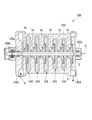
- FIG. 1 is a configuration diagram showing a schematic configuration of a centrifugal compressor 100 which is a rotary machine of the first embodiment.
- the rotary shaft 5 is rotatably supported by the casing 105 of the centrifugal compressor 100 via a journal bearing 105a and a thrust bearing 105b.
- the rotating shaft 5 is rotatable around the axis O.
- a plurality of impellers 10 are attached to the rotary shaft 5 side by side in the direction of the axis O.
- Each impeller 10 compresses the gas G supplied from the upstream flow path 104 formed in the casing 105 to the downstream flow path 104 in a stepwise manner using centrifugal force generated by the rotation of the rotary shaft 5. Shed.
- a suction port 105c for allowing the gas G to flow from the outside is formed on the front side (left side in FIG. 1) of the rotation shaft 5 in the axis O direction.
- the casing 105 is formed with a discharge port 105d for allowing the gas G to flow out to the outside on the rear side in the axis O direction (right side in FIG. 1).
- the left side of the drawing is referred to as “front side”
- the right side of the drawing is referred to as “rear side”.
- FIG. 1 shows an example in which six impellers 10 are provided in series on the rotary shaft 5, it is sufficient that at least one impeller 10 is provided on the rotary shaft 5.
- the case where one impeller 10 is provided on the rotating shaft 5 will be described as an example for the sake of simplicity.
- the impeller 10 includes a disk portion 30 that is fixed to the rotating shaft 5, and a plurality of blade portions 40 that protrude from the front side surface 31 in the axis O direction of the disk portion 30. It is equipped with.
- the impeller 10 is a so-called open type impeller.
- the disk portion 30 includes a cylindrical tube portion 32 that is fixed to the rotating shaft 5 by fitting.
- the cylinder part 32 includes a grip part 33 and a non-grip part 34.
- the grip portion 33 is provided on the front side which is the first direction side in the axis O direction.
- the grip portion 33 is fixed to the outer peripheral surface of the rotating shaft 5.
- the non-grip portion 34 is provided on the rear side which is the second direction side in the axis O direction with respect to the grip portion 33.
- the non-grip portion 34 is formed to have a diameter slightly larger than the outer diameter of the rotating shaft 5 and has a gap with the outer peripheral surface of the rotating shaft 5. That is, a part of the disk portion 30 in the direction of the axis O is fixed to the rotating shaft as the grip portion 33.
- the grip portion 33 is formed to have a smaller diameter than that of the rotating shaft 5 when not fixed to the rotating shaft 5.
- the grip portion 33 is fixed to the rotating shaft 5 by fitting by shrink fitting or the like.
- the disk unit 30 includes a disk main body 35 on the rear side in the axis O direction with respect to the grip 33.
- the disc main body portion 35 is formed in a disc shape extending from the non-grip portion 34 of the cylindrical portion 32 toward the radially outer side.
- the disc body 35 is formed thicker toward the inner side in the radial direction.
- the disk portion 30 includes a concave curved surface 31 a that smoothly connects the front side surface 31 and the outer peripheral surface 32 a of the cylindrical portion 32.
- the blade part 40 protrudes from the front side surface 31 of the disk part 30 toward the front side in the axis O direction.
- the blade part 40 has a certain plate thickness.
- the blade part 40 is slightly tapered toward the radially outer side in a side view.
- a plurality of blade portions 40 are arranged at predetermined intervals in the circumferential direction of the disc main body portion 35.
- the flow path 104 described above includes the front side surface 31 of the impeller 10, the curved surface 31 a, the outer peripheral surface 32 a, and the surface 40 a of the blade portion 40 that are opposed to each other in the circumferential direction at the location where the impeller 10 is disposed.
- a front wall 31 and a wall surface 105e of the casing 105 facing the curved surface 31a are formed.
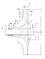
- the disk portion 30 described above includes a cylindrical reinforcing member mounting portion 50 constituting a part of the cylindrical portion 32 on the rear side in the axis O direction from the disk main body portion 35.
- the outer diameter of the reinforcing member mounting portion 50 is formed larger than the outer diameter of the cylindrical portion 32 in the grip portion 33 described above.
- FIG. 2 the position of the rearmost side in the axis O direction on the base side of the disc main body 35 is indicated by a CC line.
- a portion formed on the rear side in the axis O direction with respect to the CC line is a reinforcing member mounting portion 50.
- a reinforcing member 53 is attached to the reinforcing member attaching portion 50 so as to cover from the outside. As shown in FIGS. 2 and 3, the reinforcing member 53 restricts the deformation of the reinforcing member mounting portion 50 toward the radially outer side.
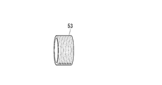
- the reinforcing member 53 is formed in a cylindrical shape having an inner diameter slightly smaller than the outer diameter of the reinforcing member mounting portion 50.
- the reinforcing member 53 is made of a material having a specific strength higher than that of the disk portion 30. Further, the reinforcing member 53 is attached to the reinforcing member attaching portion 50 in a state where one end face thereof is in contact with the rear side face 51.
- the above-mentioned specific strength is, in other words, yield stress / density.
- the specific rigidity of the material forming the reinforcing member 53 is higher than the specific rigidity of the material forming the disk portion 30.
- the impeller 10 described above is formed of an alloy such as stainless steel or titanium alloy, for example.
- an alloy such as stainless steel or titanium alloy
- CFRP carbon fiber reinforced plastic
- ceramic, magnesium alloy, etc. having a higher specific strength than the material forming the impeller 10 such as stainless steel or titanium alloy.
- CFRP carbon fiber reinforced plastic
- ceramic, magnesium alloy and the like it is preferable to use those having higher specific rigidity than alloys such as stainless steel and titanium alloy.
- carbon fiber reinforced plastic is used as the reinforcing member 53, the carbon fiber used as the reinforcing material as shown by an arrow in FIG.
- the carbon fiber 3 is at least a carbon fiber extending in the circumferential direction so as to be wound around the reinforcing member mounting portion 50. Is included. Thus, since the carbon fiber extends in the circumferential direction, it is difficult to deform in the radial direction.
- the material of the reinforcing member 53 is preferably 1 to 2.5 times the Young's modulus of the alloy that is the material of the impeller 10.
- the Young's modulus of the titanium alloy is about 113 GPa.
- the reinforcing member 53 is set to the maximum value of the rotational speed of the rotating shaft 5 (the maximum value of the hoop stress acting on the impeller 10) and the minimum length B and thickness t. preferable.
- the maximum value of the hoop stress acting on the impeller 10 is reduced as the value of the thickness t of the reinforcing member 53 is increased.
- the diameter of the impeller 10 is “D”
- the ratio of the diameter r2 of the reinforcing member 53 to the diameter D of the disc main body 35 is set to 0.35 to 0.8. More preferably, it is 0.42 to 0.66. As described above, the outer diameter r1 of the reinforcing member mounting portion 50 is only slightly larger than the inner diameter of the reinforcing member 53, and the diameter r2 of the reinforcing member 53 is equal to (r1 + 2t).
- FIG. 5 shows local stress in the impeller 10 when the ratio of the inner diameter of the reinforcing member 53 to the diameter of the disk main body 35 (reinforcing member mounting position (diameter) r2 / disk diameter D) is changed. It is a graph which shows the change of a size (maximum stress of a disk). In the graph of FIG. 5, “a1” is an upper limit value of allowable stress in the impeller 10, and “a2” indicates a more preferable upper limit value of stress in the impeller 10.
- the stress concerning the impeller 10 is suppressed to the stress which is less than the upper limit value a1 and the upper limit value a2.
- the stress of the impeller 10 is higher than the upper limit value a2 and is equal to the upper limit value a1. This is because the strength of the reinforcing member mounting portion 50 is insufficient due to the outer diameter r1 of the reinforcing member mounting portion 50 becoming too small, and the connecting portion between the reinforcing member mounting portion 50 and the disc main body portion 35 is deformed. This is probably because the hoop stress at the deformed portion increases.
- the ratio of the diameter of the reinforcing member 53 to the diameter of the disk main body 35 is preferably 0.42 to 0.66 in which the stress applied to the impeller 10 is lower than the upper limit value a1. Furthermore, it is more preferable that the stress applied to the impeller 10 is 0.35 to 0.8 below the upper limit value a2.
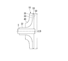
- FIG. 6 is a contour diagram showing a simulation result of stress distribution during high-speed rotation in the impeller 10 of this embodiment.
- the portion where high stress is applied is shown in darker color.
- the centrifugal force when the impeller 10 not provided with the reinforcing member 53 is rotating has a maximum value on or near the CC line along the rear side surface 51 of the disk main body portion 35. Therefore, the hoop stress shows the maximum stress at the location where the CC line and the innermost diameter portion of the non-grip portion 34 intersect or in the vicinity thereof.
- the range in which the stress applied during rotation increases is wider in the direction of the axis O than in the case of an impeller that does not include the reinforcing member 53 (see FIG. 12, for example). Is showing. However, the maximum value has been reduced. This is because the reinforcing member 53 increases the rigidity of the cylindrical portion 32 in the radial direction due to centrifugal force, so that the impeller 10 is prevented from being deformed so as to float radially outward on the second direction side in the axis O direction. Because. That is, in the impeller 10, the local increase in the hoop stress caused by the deformation in the radial direction is suppressed.
- FIGS. 7A to 7C show an example of a procedure for attaching the impeller 10 to the rotary shaft 5 as an assembling method of the centrifugal compressor 100.
- the reinforcing member 53 is attached to the reinforcing member attaching portion 50 of the impeller 10 (attachment process).
- a method of attaching the reinforcing member 53 cold fitting, shrink fitting, or the like can be used.
- the reinforcing member 53 is CFRP and the reinforcing member 53 is attached to the reinforcing member attaching portion 50 by shrink fitting, for example, a loose fastening allowance is used and shrink fitting is performed at 100 ° C. or less in order to reduce the thermal load on the CFRP. It is preferable to carry out.
- the reinforcing member 53 is CFRP
- the reinforcing member 53 may be attached to the reinforcing member attaching portion 50 with a predetermined tension applied.
- the impeller 10 is attached to the rotating shaft 5 by cold fitting or shrink fitting (impeller mounting step).
- the reinforcing member 53 is CFRP and the impeller 10 is shrink-fitted on the rotating shaft 5
- the reinforcing member 53 is heated to 100 ° C. by locally heating the grip portion 33 in order to reduce the thermal load on the CFRP. It is preferable not to exceed.
- the reinforcing member 53 made of a material having higher specific strength than the impeller 10 is provided on the reinforcing member mounting portion 50 formed on the cylindrical portion 32 on the rear side in the axis O direction. Is attached, the rigidity with respect to the deformation
- the length of the disc portion 30 in the axis O direction can be shortened, and the length in the axis O direction is shortened.
- the weight of the impeller 10 can be reduced.
- the stress at the time of rotation can be sufficiently reduced while being configured to be easily detachable from the rotating shaft 5.
- the span of the impeller 10 in the direction of the axis O can be shortened and the weight can be reduced, the impeller 10 can be rotated at a sufficiently high speed while suppressing the shaft vibration.
- the grip part 33 is formed only in a part on the front side in the direction of the axis O, the impeller 10 can be easily attached to and detached from the rotating shaft 5. As a result, maintainability can be improved.
- the ratio of the diameter r2 of the reinforcing member 53 to the diameter D of the disc main body 35 is larger than 0.8, the thickness of the cylindrical portion 32 in the radial direction increases and the centrifugal force applied to the cylindrical portion 32 is increased. As a result, the reinforcing member 53 becomes larger.
- the ratio of the diameter r2 of the reinforcing member 53 to the diameter D of the disk main body 35 is smaller than 0.35, the thickness of the cylindrical portion 32 is excessively decreased, and the cylindrical portion 32 is insufficient due to insufficient strength of the cylindrical portion 32. It will not suppress the deformation of 32.
- the ratio of the diameter r2 of the reinforcing member 53 to the diameter D of the disk main body portion 35 is 0.35 to 0.8, so that hoop stress due to centrifugal force is efficiently suppressed. be able to.
- the impeller 210 according to the second embodiment of the present invention will be described with reference to the drawings.
- the impeller 210 according to the second embodiment is different from the impeller 10 according to the first embodiment described above only in the configuration of the reinforcing member mounting portion. Therefore, the same parts as those in the first embodiment described above are denoted by the same reference numerals, and detailed description thereof is omitted.
- the impeller 210 according to the second embodiment is an open type impeller having a disk portion 30 and a blade portion 40, similar to the impeller 10 according to the first embodiment described above.
- the disk unit 30 includes a disk main body unit 35 and a cylinder unit 32.
- the disc main body portion 35 is formed in a disc shape extending from the non-grip portion 34 toward the radially outer side.
- the disc body 35 is formed thicker toward the inner side in the radial direction.
- the disk portion 30 includes a concave curved surface 31 a that smoothly connects the front side surface 31 and the outer peripheral surface 32 a of the cylindrical portion 32.
- the blade part 40 is formed so as to protrude from the front side surface 31 of the disk part 30.
- the disk part 30 described above includes a cylindrical reinforcing member mounting part 250 constituting a part of the cylindrical part 32 on the rear side in the axis O direction from the disk main body part 35.
- the reinforcing member attachment portion 250 includes an attachment portion main body 54 and a ring member 55.
- the attachment portion main body 54 is formed integrally with the above-described cylinder portion 32.
- the ring member 55 is formed separately from the cylindrical portion 32.
- the ring member 55 is attached to the attachment portion main body 54.
- the ring member 55 is formed of a material having a linear expansion coefficient equal to or higher than that of the material forming the attachment portion main body 54, that is, the material forming the cylindrical portion 32.
- As a material for forming the ring member 55 for example, an alloy such as stainless steel or a titanium alloy, a magnesium alloy, or the like can be used.
- the ring member 55 has an accommodation groove 55a formed on the outer peripheral surface thereof.
- the housing groove 55 a is formed in an annular shape so as to extend over the entire circumference of the outer peripheral surface of the ring member 55.
- the reinforcing member 53 is accommodated in the accommodation groove 55a.
- the reinforcing member 53 is formed in the same manner as in the first embodiment described above, and is formed in a cylindrical shape by, for example, CFRP.
- CFRP As a material for forming the reinforcing member 53, a material having a higher specific strength than the mounting portion main body 54 and the ring member 55, more specifically, a material having a higher specific strength and specific rigidity is used.
- the reinforcing member 53 is attached to the ring member 55, and the ring member 55 is attached to the attachment portion main body 54.
- step S01 which attaches the reinforcement member 53 to the ring member 55 first is performed.
- the reinforcing member 53 is CFRP
- the carbon fiber used as the reinforcing material is wound around the ring member 55 in a state where a predetermined tension is applied so that carbon fibers that face the circumferential direction are included.
- a ring member attaching step for attaching the ring member 55 to which the reinforcing member 53 is attached to the attaching portion main body 54 is performed.
- the ring member 55 is fixed to the attachment portion main body 54 by cold fitting, shrink fitting or the like.
- the reinforcing member 53 is CFRP
- the ring member 55 is heated and attached in a state where the CFRP is 100 ° C. or lower when shrink fitting is performed.
- an impeller attachment step (step S03) is performed in which the impeller 210 to which the ring member 55 is attached is fixed to the rotary shaft 5 by fitting by cold fitting, shrink fitting, or the like.
- the reinforcing member 53 may be attached to the ring member 55 by winding the reinforcing member 53 around the outer periphery of the ring member 55 with a predetermined tension without providing the receiving groove portion 55 a in the ring member 55.
- the ring member 55 is formed of a material having a linear expansion coefficient equal to or higher than the linear expansion coefficient of the attachment main body 54, thereby heating the ring member 55 and attaching the attachment part.
- the ring member 55 can be removed from the attachment part main body 54 in a state where the temperature difference between the attachment part main body 54 and the ring member 55 is smaller.
- the reinforcing member 53 can be easily detached from the attachment portion main body 54 while suppressing a thermal load on the reinforcing member 53 due to a temperature rise.
- the reinforcing member 53 can be attached to the attaching portion main body 54 by attaching the ring member 55 to the cylindrical portion 32. Therefore, the reinforcing member 53 can be easily attached to the attachment portion main body 54.
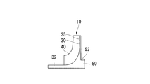
- an impeller 310 according to a third embodiment of the present invention will be described with reference to the drawings.
- the impeller 310 of the third embodiment is different from the impeller 210 of the second embodiment described above only in the configuration of the grip portion 33. Therefore, the same parts as those in the second embodiment described above are denoted by the same reference numerals, and detailed description thereof is omitted.
- the impeller 310 of the third embodiment is an open type impeller having a disk portion 30 and a blade portion 40, similarly to the impeller 210 of the second embodiment described above.
- the disk unit 30 includes a disk main body unit 35 and a cylinder unit 32.
- the cylindrical portion 32 includes a cylindrical reinforcing member mounting portion 250 that constitutes a part of the cylindrical portion 32 on the rear side in the axis O direction from the disc main body portion 35.
- the reinforcing member attaching portion 250 includes an attaching portion main body 54 and a ring member 55.
- the reinforcing member 53 is attached to the reinforcing member attaching portion 250 so as to cover from the outside.
- the cylinder portion 32 includes a grip portion 33 that is fixed to the outer peripheral surface of the rotating shaft 5.
- the grip portion 33 is disposed on the rear side in the axis O direction with respect to the disc main body portion 35. More specifically, the grip portion 33 is disposed on the rear side in the axis O direction with respect to the reinforcing member mounting portion 50.
- the cylinder portion 32 includes a non-grip portion 34 on the front side which is the first direction side in the axial direction.
- a grip holding member 56 is attached to the cylinder portion 32.
- the grip holding member 56 reinforces the cylindrical portion 32 in the grip portion 33 by pressing the grip portion 33 from the outside in the radial direction.
- the grip holding member 56 is formed such that its length in the direction of the axis O is sufficiently shorter than the length of the grip portion 33.
- the grip holding member 56 is attached at a position where the grip portion 33 of the cylindrical portion 32 is disposed. More specifically, the grip holding member 56 is attached to a position on the most front side of the grip portion 33.
- the grip holding member 56 includes a grip ring member 57 and a grip reinforcement member 58.
- the grip ring member 57 is formed of the same material as that of the ring member 55 described above, and the inner diameter of the grip ring member 57 is slightly smaller than the outer diameter of the cylindrical portion 32 at the attachment location when the grip ring member 57 is not attached to the cylindrical portion 32.
- the grip ring member 57 is formed with a ring-shaped accommodation groove 59 similarly to the accommodation groove 55a described above.
- the accommodation groove 59 accommodates a cylindrical grip reinforcement member 58 formed of the same material as the reinforcement member 53 described above.
- the grip holding member 56 is attached to the cylindrical portion 32 by cold fitting or shrink fitting after the above-described ring member 55 is attached to the attachment portion main body 54 as in the case of the above-described ring member 55. .
- the grip holding member 56 includes the grip ring member 57
- the grip ring member 57 may be omitted and the grip reinforcing member 58 may be directly attached to the cylindrical portion 32.
- the inner diameter of the ring member 55 is equal to the outer diameter of the grip ring member 57, but the thickness of the grip ring member 57 in the radial direction is the same as that of FIGS. 10 and 11.
- the thickness is not limited and is set to an optimum thickness according to the strength and rigidity of the cylindrical portion 32.
- the ring member 55 may be attached to the attachment portion main body 54 after the grip ring member 57 is attached to the cylindrical portion 32. good.
- the grip reinforcing member 58 can restrict the deformation of the grip portion 33 to the outside in the radial direction due to the centrifugal force. Therefore, it is possible to reduce the hoop stress applied to the cylindrical portion 32 in the vicinity of the grip portion 33 and at the same time more firmly fix the impeller 310 to the rotating shaft 5.
- the present invention is not limited to the configuration of each of the embodiments described above, and the design can be changed without departing from the gist thereof.
- the open type impeller having only the disk portion 30 and the blade portion 40 has been described as an example.
- the present invention is not limited to this case.
- the present invention can be similarly applied to a closed impeller having a cover portion for the disk portion 30 and the blade portion 40.
- centrifugal compressor 100 is described as the rotary machine.
- the present invention is not limited to the centrifugal compressor 100, and may be applied to, for example, various industrial compressors, turbo refrigerators, and small gas turbines.
- the impeller can be applied.
- the present invention can be easily attached to and detached from the rotating shaft, and the hoop stress during rotation can be sufficiently reduced, and further high-speed rotation is possible.
- Impeller 30 Disc part 31 Front side surface 31a Curved surface 32 Tube part 32a Outer peripheral surface 33 Grip part 34 Non-grip part 35 Disc main body part 40 Blade part 40a Surface 50 Reinforcement member attachment part 51 Rear side surface 53 Reinforcement member 54 Attachment part main body 55 Ring member 55a Housing groove portion 56 Grip holding member 57 Grip ring member 58 Grip reinforcement member 59 Housing groove portion 100 Centrifugal compressor 104 Channel 105 Casing 105a Journal bearing 105b Thrust bearing 105c Suction port 105d Discharge port 105e Wall surface 210 Impeller 250 Attaching the reinforcing member Part 310 impeller 610 impeller 710 impeller a1 upper limit value a2 upper limit value D diameter G gas O axis r1 outer diameter r2 diameter
Abstract
軸線(O)回りに回動される回転軸(5)が挿通され、回転軸(5)の軸線(O)方向の一部がグリップ部(33)として回転軸(5)に固定される筒部(32)と、筒部(32)から回転軸(5)の径方向外側に向かって延びるディスク本体部(35)と、を備えたディスク部(30)と、ディスク本体部(35)から軸線(O)方向の第一方向側に突出するブレード部(40)と、ディスク本体部(35)よりも軸線(O)方向の第二方向側の筒部(32)に形成される補強部材取付部(50)と、ディスク部(30)よりも比強度の高い材料により形成され、補強部材取付部(50)に外側から覆うように取り付けられる補強部材(53)と、を備える。
Description
この発明は、インペラ、インペラが回転軸に固定されてなる回転機械、および、回転機械の組立方法に関する。
本願は、2013年6月4日に、日本に出願された特願2013-117596号に基づき優先権を主張し、その内容をここに援用する。
本願は、2013年6月4日に、日本に出願された特願2013-117596号に基づき優先権を主張し、その内容をここに援用する。
ターボ冷凍機や小型ガスタービン等にあっては、遠心圧縮機などの回転機械を備えているものがある。遠心圧縮機は、回転軸に固定されたディスク部に複数のブレードが設けられたインペラを有している。遠心圧縮機は、これらインペラを回転させることで、ガスに圧力エネルギー及び速度エネルギーを与えている。
例えば、水素などの軽い流体を圧縮する場合や、より高い過給圧を得る場合などには、上記遠心圧縮機のインペラを高速回転させる必要がある。より具体的には、水素を圧縮する場合には、例えば、インペラの回転数を数千rpmから数万rpmまで上昇させるなど、インペラを高速回転させる必要がある。特に、インペラの径方向中央部に形成された取付孔に回転軸が挿入されて、取付孔の内周面全体が回転軸にグリップされるものにおいては、インペラを高速回転させた場合、取付孔の内周面近傍の引っ張り応力が高くなり破損する可能性があった。
そこで、上記内周面近傍の引っ張り応力が高くなることを防止するために、取付孔の内周面に、応力低減窪みを形成することが提案されている(例えば、特許文献1参照)。
そこで、上記内周面近傍の引っ張り応力が高くなることを防止するために、取付孔の内周面に、応力低減窪みを形成することが提案されている(例えば、特許文献1参照)。
上記インペラには、回転軸への着脱を容易にしてメンテナンス性等を向上するために、筒部の前方に、回転軸に固定されるグリップ部を有したものがある。
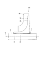
図12は、前方にグリップ部33を有したインペラ610において高速回転時に作用する応力のシミュレーション結果を示すコンタ図である。このインペラ610は、ディスク部30とブレード部40とからなる、いわゆるオープン型のインペラである。図13に示すように、ディスク部30は、回転軸5に対してこの回転軸5の軸線O方向前側のグリップ部(図13中、左側部)33が焼き嵌め等により固定される筒部32と、グリップ部33よりも軸線O方向後側に設けられて回転軸5の径方向外側に向かって延びるディスク本体部35とを備えている。
図12は、前方にグリップ部33を有したインペラ610において高速回転時に作用する応力のシミュレーション結果を示すコンタ図である。このインペラ610は、ディスク部30とブレード部40とからなる、いわゆるオープン型のインペラである。図13に示すように、ディスク部30は、回転軸5に対してこの回転軸5の軸線O方向前側のグリップ部(図13中、左側部)33が焼き嵌め等により固定される筒部32と、グリップ部33よりも軸線O方向後側に設けられて回転軸5の径方向外側に向かって延びるディスク本体部35とを備えている。
このように形成されたインペラ610において、回転軸5の高速回転時に作用する応力が最大となる箇所(応力が集中する箇所)は、上記グリップ部33とは反対側の、軸線O方向後方側の角部近傍となる。これは、回転時の遠心力や流路側とディスク後側面側とのガス圧差により生じるスラスト方向荷重(スラスト力)などによって、ディスク部30の角部が、図13中の破線に示す径方向外側に変位しようとするからである。この角部近傍における応力集中は、インペラ610の周方向に作用する引っ張り応力であるフープ応力が主体となる。図13において、フープ応力が集中する箇所を符号「f」で示している。
上記ディスク部30の角部近傍におけるフープ応力の大きさは、高速回転になるほど増大する。そのため、例えば、意図しない高速回転となった場合には、ディスク部30が強度不足に陥る可能性がある。この強度不足を防止するためには、例えば、筒部32の内周全面で筒部32を回転軸5の外周面に固定させる方法が考えられる。更に、特許文献1のように複数個所で、筒部32を回転軸5の外周面に固定させる方法も考えられる。しかし、回転軸5からインペラ610を取り外す際などに、ディスク部30の広範囲に亘り温度上昇させる必要があり、組立性及びメンテナンス性が悪くなってしまう。また、上述したように引張応力が大きくなってしまう。
一方で、組立性及びメンテナンス性を悪化させずにディスク部30の角部近傍におけるフープ応力を低減させるためには、例えば、図14に示すインペラ710のように、ディスク部30の後側面側の肉厚を増加させることが考えられる。図15は、ディスク部30の後側面側の肉厚を増加させた場合のシミュレーション結果を示すコンタ図である。この図15に示すようにディスク部30の後側面側の肉厚を増加させて等応力状態に近い形状とすることで、上述した図12の場合よりもフープ応力の大きさが全体的に小さくなる。
しかしながら、図16に示すように、軸線O方向前側にグリップ部33を有する場合、軸線O方向の中央部に、図16中破線で示すように、曲げ戻しが発生して十分な応力低減を図ることができない可能性がある。また、インペラ610の重量が増加するとともに、インペラ610の軸線O方向のスパンが長くなることで、軸振動が増大してインペラ610を高速回転できない可能性がある。
しかしながら、図16に示すように、軸線O方向前側にグリップ部33を有する場合、軸線O方向の中央部に、図16中破線で示すように、曲げ戻しが発生して十分な応力低減を図ることができない可能性がある。また、インペラ610の重量が増加するとともに、インペラ610の軸線O方向のスパンが長くなることで、軸振動が増大してインペラ610を高速回転できない可能性がある。
この発明は、回転軸に対して容易に着脱可能であると共に回転時の応力を十分に低減可能であり、更なる高速回転が可能なインペラ、インペラを備える回転機械、および、回転機械の組立方法を提供する。
本発明の第一態様によれば、インペラは、軸線回りに回動される回転軸が挿通され、前記回転軸の軸線方向の一部がグリップ部として前記回転軸に固定される筒部と、前記筒部から前記回転軸の径方向外側に向かって延びるディスク本体部と、を備えたディスク部と、前記ディスク本体部から軸線方向の第一方向側に突出するブレードと、前記ディスク本体部よりも前記軸線方向の第二方向側の前記筒部に形成される補強部材取付部と、前記ディスク部よりも比強度の高い材料により形成され、前記補強部材取付部に外側から覆うように取り付けられる補強部材と、を備えている。
本発明の第二態様によれば、インペラは、第一態様のインペラにおける前記補強部材取付部が、前記筒部と一体に形成される取付部本体と、前記取付部本体の線膨張率以上の線膨張率を有する材料により形成され、前記取付部本体に取り付けられるリング部材と、を備え、前記補強部材が、前記リング部材に取り付けられていてもよい。
本発明の第三態様によれば、インペラは、第一又は第二態様のインペラにおいて、前記補強部材よりも前記軸線方向の第二方向側に前記グリップ部が配され、前記筒部の前記グリップ部が配される位置に取り付けられて前記グリップ部を補強するグリップ補強部材を備えていてもよい。
本発明の第四態様によれば、インペラは、第一から第三態様の何れか一つのインペラにおいて、前記ディスク本体部の直径に対する前記補強部材の直径の比率が、0.35から0.8であってもよい。
本発明の第五態様によれば、回転機械は、第一から第四態様の何れか一つのインペラを備えている。
本発明の第六態様によれば、回転機械の組立方法は、第一態様のインペラを備える回転機械の組立方法であって、補強部材を前記補強部材取付部に取り付ける取付工程と、前記インペラを前記回転軸に取り付けるインペラ取付工程と、を備えている。
本発明の第七態様によれば、回転機械の組立方法は、第二態様のインペラを備える回転機械の組立方法であって、前記補強部材を前記リング部材に取り付ける補強部材取付工程と、前記補強部材が取り付けられた前記リング部材を前記取付部本体に取り付けるリング部材取付工程と、前記インペラを前記回転軸に取り付けるインペラ取付工程と、を備えている。
この発明によれば、回転軸に対して容易に着脱可能であると共に回転時のフープ応力を十分に低減可能であり、更なる高速回転が可能となる。
次に、この発明の第一実施形態における回転機械およびインペラについて図面を参照して説明する。
図1は、第一実施形態の回転機械である遠心圧縮機100の概略構成を示す構成図である。
図1に示すように、遠心圧縮機100のケーシング105には、ジャーナル軸受105aおよびスラスト軸受105bを介して回転軸5が回転可能に支持されている。回転軸5は、軸線O回りに回動可能とされている。この回転軸5には、軸線O方向に複数のインペラ10が並んで取り付けられている。各インペラ10は、回転軸5の回転による遠心力を利用してケーシング105に形成された上流側の流路104から供給されるガスGを下流側の流路104へと段階的に圧縮して流す。
図1は、第一実施形態の回転機械である遠心圧縮機100の概略構成を示す構成図である。
図1に示すように、遠心圧縮機100のケーシング105には、ジャーナル軸受105aおよびスラスト軸受105bを介して回転軸5が回転可能に支持されている。回転軸5は、軸線O回りに回動可能とされている。この回転軸5には、軸線O方向に複数のインペラ10が並んで取り付けられている。各インペラ10は、回転軸5の回転による遠心力を利用してケーシング105に形成された上流側の流路104から供給されるガスGを下流側の流路104へと段階的に圧縮して流す。
ケーシング105には、回転軸5の軸線O方向の前方側(図1における左側)に、外部からガスGを流入させるための吸込口105cが形成されている。ケーシング105には、軸線O方向の後方側(図1における右側)に、外部へガスGを流出させるための排出口105dが形成されている。以下の説明においては、紙面左側を「前方側」、紙面右側を「後方側」と称する。
上記遠心圧縮機100によれば、回転軸5が回転すると、吸込口105cからガスGが流路104に流入して、このガスGがインペラ10によって段階的に圧縮されて排出口105dから排出される。ここで、図1においては、回転軸5にインペラ10が直列に6個設けられた一例を示しているが、回転軸5に対して少なくとも1個のインペラ10が設けられていればよい。以下の説明では、説明を簡単化するため、回転軸5にインペラ10が1個設けられている場合を一例にして説明する。
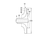
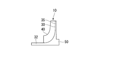
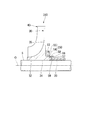
図2に示すように、上記インペラ10は、回転軸5に対して固定されるディスク部30と、このディスク部30の軸線O方向の前側面31から突出して設けられた複数のブレード部40と、を備えている。インペラ10は、いわゆるオープン型のインペラである。
ディスク部30は、回転軸5に対して嵌め合いにより固定される円筒状の筒部32を備えている。筒部32は、グリップ部33と非グリップ部34とを備えている。
グリップ部33は、軸線O方向の第一方向側となる前方側に設けられている。グリップ部33は、回転軸5の外周面に固定される。
非グリップ部34は、グリップ部33よりも軸線O方向の第二方向側となる後方側に設けられている。非グリップ部34は、回転軸5の外径よりも僅かに大径に形成されて回転軸5の外周面との間に隙間を有している。つまり、ディスク部30は、軸線O方向の一部がグリップ部33として回転軸に固定されている。このグリップ部33は、回転軸5に固定されていない状態では回転軸5よりも小径となるように形成されている。グリップ部33は、回転軸5に対して焼き嵌め等による嵌め合いにより固定されている。
グリップ部33は、軸線O方向の第一方向側となる前方側に設けられている。グリップ部33は、回転軸5の外周面に固定される。
非グリップ部34は、グリップ部33よりも軸線O方向の第二方向側となる後方側に設けられている。非グリップ部34は、回転軸5の外径よりも僅かに大径に形成されて回転軸5の外周面との間に隙間を有している。つまり、ディスク部30は、軸線O方向の一部がグリップ部33として回転軸に固定されている。このグリップ部33は、回転軸5に固定されていない状態では回転軸5よりも小径となるように形成されている。グリップ部33は、回転軸5に対して焼き嵌め等による嵌め合いにより固定されている。
ディスク部30は、グリップ部33よりも軸線O方向の後方側にディスク本体部35を備えている。ディスク本体部35は、筒部32の非グリップ部34から径方向外側に向かって延びる円板状に形成されている。ディスク本体部35は、径方向内側に向かうほど厚肉に形成されている。
ディスク部30は、前側面31と、筒部32の外周面32aとを滑らかに繋ぐ凹状の曲面31aを備えている。
ディスク部30は、前側面31と、筒部32の外周面32aとを滑らかに繋ぐ凹状の曲面31aを備えている。
ブレード部40は、ディスク部30の前側面31から軸線O方向前側に向かって突出している。ブレード部40は、一定の板厚を有している。ブレード部40は、側面視で径方向外側に向かってやや先細り形状とされている。また、ブレード部40は、ディスク本体部35の周方向に所定の間隔をあけて複数配列されている。ここで、上述した流路104は、インペラ10が配置される箇所において、インペラ10の前側面31と、曲面31aと、外周面32aと、周方向に互いに対向するブレード部40の面40aと、前側面31および曲面31aに対向するケーシング105の壁面105eとにより形成されている。
上述したディスク部30は、ディスク本体部35よりも軸線O方向の後方側に、筒部32の一部を構成する円筒状の補強部材取付部50を備えている。この補強部材取付部50の外径は、上述したグリップ部33における筒部32の外径よりも大径に形成されている。図2中、ディスク本体部35の基部側における最も軸線O方向後側の位置をC-C線で示している。このC-C線よりも軸線O方向後側に形成されている部分が補強部材取付部50となっている。
補強部材取付部50には、補強部材53が外側から覆うようにして取り付けられている。
図2、図3に示すように、補強部材53は、補強部材取付部50の径方向外側への変形を規制する。補強部材53は、補強部材取付部50の外径よりも僅かに小さい内径を有した円筒状に形成されている。この補強部材53は、ディスク部30よりも比強度が高い材料により構成されている。また、補強部材53は、その片方の端面が、後側面51に当接した状態で補強部材取付部50に取り付けられる。ここで、上述した比強度とは、言い換えれば、降伏応力/密度である。補強部材53を形成する材料の比剛性は、ディスク部30を形成する材料の比剛性よりも高くなっている。
図2、図3に示すように、補強部材53は、補強部材取付部50の径方向外側への変形を規制する。補強部材53は、補強部材取付部50の外径よりも僅かに小さい内径を有した円筒状に形成されている。この補強部材53は、ディスク部30よりも比強度が高い材料により構成されている。また、補強部材53は、その片方の端面が、後側面51に当接した状態で補強部材取付部50に取り付けられる。ここで、上述した比強度とは、言い換えれば、降伏応力/密度である。補強部材53を形成する材料の比剛性は、ディスク部30を形成する材料の比剛性よりも高くなっている。
上述したインペラ10は、例えば、ステンレスやチタン合金などの合金により形成されている。一方で、補強部材53を構成する材料としては、上記ステンレスやチタン合金などのインペラ10を形成する材料よりも比強度が高い炭素繊維強化プラスチック(以下、単にCFRPと称する)、セラミック、マグネシウム合金などを用いることができる。これら、CFRP、セラミック、マグネシウム合金などは、さらにステンレスやチタン合金などの合金よりも比剛性が高いものを用いることが好ましい。例えば、炭素繊維強化プラスチックを補強部材53として用いる場合、図3に矢印で示すように強化材として用いられる炭素繊維は、少なくとも補強部材取付部50に巻回されるように周方向に延びる炭素繊維を含んでいる。このように炭素繊維が周方向に延びることで、径方向への変形がし難くなっている。
補強部材53の材料は、インペラ10の材料である合金のヤング率に対して、1~2.5倍のヤング率とすることが好ましい。例えば、チタン合金のヤング率は113GPa程度である。上記補強部材53のヤング率を上記のように設定することで、回転時の遠心力によるフープ応力によって補強部材取付部50が径方向外側に変形することを、補強部材取付部50よりもヤング率が高い補強部材53によって抑えることが可能となる。
補強部材53は、軽量化の観点から、回転軸5における回転数の最大値(インペラ10に作用するフープ応力の最大値)と、最小限の長さBや厚さtに設定されるのが好ましい。インペラ10に作用するフープ応力の最大値は、補強部材53の厚さtの値が大きいほど低減される。ここで、上記補強部材53の厚さ「t」は、インペラ10の直径を「D」とすると、補強部材53の重量増大を可能な限り抑制する上で、t/D=0.015~0.06とすることが好ましい。また、補強部材53の幅「B」は、インペラ10の軸線O方向のスパンを抑制する上で、B/D=0.01~0.03とすることが好ましいが、B/D>0.03としてもよい。
ディスク本体部35の直径Dに対する補強部材53の直径r2の比率は、0.35から0.8とされる。より好ましくは、0.42から0.66とされる。上述したように、補強部材取付部50の外径r1は、補強部材53の内径に対して僅かに大きいだけであり、補強部材53の直径r2は、(r1+2t)と同等の値となる。
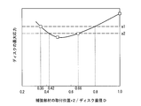
図4A~図4Dは、補強部材53の直径r2を、ディスク本体部35の直径Dの範囲内でそれぞれ変化させた一例を示している。また、図5は、ディスク本体部35の直径に対する補強部材53の内径の比率(補強部材の取り付け位置(直径)r2/ディスク直径D)を変化させた場合の、インペラ10における局所的な応力の大きさ(ディスクの最大応力)の変化を示すグラフである。図5のグラフ中、「a1」は、インペラ10における許容応力の上限値であって、「a2」は、インペラ10におけるより好適な応力の上限値を示している。
図4Aは、r2/D=1の場合を示している。すなわち、ディスク本体部35の先端部とほぼ同じ位置に補強部材53が取り付けられている。図5に示すように、図4Aの場合、上限値a1よりも高い応力が発生してしまう。これは、補強部材53の内側のインペラ10のマスが増大し、補強部材53により補強部材取付部50の遠心力による変形を十分に抑えられなくなったためと考えられる。
図4B、図4Cは、それぞれr2/D=0.66と、r2/D=0.49の場合を示している。これら図4B、図4Cの場合、インペラ10にかかる応力が、上限値a1、および、上限値a2を下回る応力に抑えられている。
一方で、図4Dは、r2/D=0.35の場合を示している。図5に示すように、図4Dの場合、インペラ10の応力は、上限値a2よりも高く、上限値a1と同等の値となる。これは、補強部材取付部50の外径r1が小さくなり過ぎたことにより、補強部材取付部50の強度が不足して、補強部材取付部50とディスク本体部35との接続部分が変形して、変形箇所におけるフープ応力が増大してしまうためと考えられる。
すなわち、ディスク本体部35の直径に対する補強部材53の直径の比率は、インペラ10にかかる応力が上限値a1を下回る0.42から0.66とされることが好ましい。さらに、インペラ10にかかる応力が上限値a2を下回る0.35から0.8とされることがより好ましい。
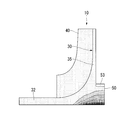
図6は、この実施形態のインペラ10における、高速回転時の応力分布のシミュレーション結果を示すコンタ図である。なお、図6においては、高い応力が作用している箇所ほど濃色で示している。ここで、一般に、補強部材53を備えていないインペラ10が回転している時の遠心力は、ディスク本体部35の後側面51に沿うC-C線上またはその近傍で最大値となる。そのため、フープ応力はC-C線と非グリップ部34の最内径部が交差する箇所またはその近傍で最大応力を示す。
図6に示すように、この実施形態におけるインペラ10の場合、回転時にかかる応力が高くなる範囲は、補強部材53を備えていないインペラ(例えば図12参照)の場合よりも、軸線O方向に広がりを見せている。しかし、その最大値は低減されている。これは、補強部材53によって遠心力による径方向への筒部32の剛性を高めることで、インペラ10が軸線O方向の第二方向側において径方向外側に浮き上がるように変形することが抑制されるためである。つまり、インペラ10において、径方向に変形することにより生じるフープ応力の局所的な増大が抑制されている。
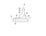
図7A~図7Cは、上記遠心圧縮機100の組立方法として、特にインペラ10を回転軸5へ取り付ける手順の一例を示している。
まず、図7A、図7Bに示すように、インペラ10の補強部材取付部50に補強部材53を取り付ける(取付工程)。この補強部材53を取り付ける方法としては、冷し嵌めや、焼嵌め等を用いることができる。補強部材53がCFRPで、焼嵌めにより補強部材53を補強部材取付部50に取り付ける場合には、CFRPへの熱的負荷を軽減するために、例えば緩い締め代とするとともに100℃以下で焼嵌めを行うことが好ましい。また、補強部材53がCFRPの場合には、所定張力をかけた状態で補強部材53を補強部材取付部50に取り付けるようにしても良い。
まず、図7A、図7Bに示すように、インペラ10の補強部材取付部50に補強部材53を取り付ける(取付工程)。この補強部材53を取り付ける方法としては、冷し嵌めや、焼嵌め等を用いることができる。補強部材53がCFRPで、焼嵌めにより補強部材53を補強部材取付部50に取り付ける場合には、CFRPへの熱的負荷を軽減するために、例えば緩い締め代とするとともに100℃以下で焼嵌めを行うことが好ましい。また、補強部材53がCFRPの場合には、所定張力をかけた状態で補強部材53を補強部材取付部50に取り付けるようにしても良い。
次いで、図7Cに示すように、回転軸5に対してインペラ10を冷し嵌めや、焼嵌めにより取り付ける(インペラ取付工程)。補強部材53がCFRPであってインペラ10を回転軸5に焼嵌めする場合、CFRPへの熱的負荷を軽減するために、グリップ部33を局部的に加熱することで、補強部材53が100℃を超えないようにすることが好ましい。
したがって、上述した第一実施形態のインペラ10によれば、軸線O方向の後方側の筒部32に形成された補強部材取付部50に、インペラ10よりも比強度の高い材料からなる補強部材53が取り付けられていることで、遠心力による筒部32の径方向外側への変形に対する剛性を高めることができる。そのため、インペラ10が軸線O方向の後方側において径方向に浮き上がるように変形することを抑制して、フープ応力の増大を抑制することができる。また、図14に示すディスク本体部35の後側面51の肉厚を増加させる場合と比較して、ディスク部30の軸線O方向の長さを短縮できるとともに、この軸線O方向の長さが短縮されることでインペラ10の軽量化を図ることができる。
その結果、回転軸5に対して容易に着脱可能な構成としつつ、回転時の応力を十分に低減可能である。さらに、軸線O方向のインペラ10のスパンを短縮できるとともに、軽量化を図ることができるため、軸振動を抑制してインペラ10を十分に高速回転させることが可能となる。さらに、グリップ部33が、軸線O方向の前方側の一部にのみ形成されるので、回転軸5に対してインペラ10を容易に着脱することができる。その結果、メンテナンス性を向上することができる。
その結果、回転軸5に対して容易に着脱可能な構成としつつ、回転時の応力を十分に低減可能である。さらに、軸線O方向のインペラ10のスパンを短縮できるとともに、軽量化を図ることができるため、軸振動を抑制してインペラ10を十分に高速回転させることが可能となる。さらに、グリップ部33が、軸線O方向の前方側の一部にのみ形成されるので、回転軸5に対してインペラ10を容易に着脱することができる。その結果、メンテナンス性を向上することができる。
また、ディスク本体部35の直径Dに対する補強部材53の直径r2の比率が0.8よりも大きい場合には、径方向における筒部32の厚さが増加して筒部32にかかる遠心力が大きくなり、補強部材53が大型化する。一方で、ディスク本体部35の直径Dに対する補強部材53の直径r2の比率が0.35よりも小さい場合には、筒部32の厚さが減少しすぎて筒部32の強度不足により筒部32の変形を抑えくれなくなる。しかし、上述した実施形態のように、ディスク本体部35の直径Dに対する補強部材53の直径r2の比率が、0.35から0.8であることで、遠心力によるフープ応力を効率よく抑制することができる。
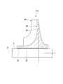
次に、この発明の第二実施形態におけるインペラ210を図面に基づき説明する。この第二実施形態のインペラ210は、上述した第一実施形態のインペラ10に対して、補強部材取付部の構成が異なるだけである。そのため、上述した第一実施形態と同一部分には同一符号を付して説明し、詳細説明を省略する。
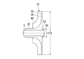
図8に示すように、この第二実施形態のインペラ210は、上述した第一実施形態のインペラ10と同様に、ディスク部30とブレード部40とを有するオープン型のインペラである。ディスク部30は、ディスク本体部35と、筒部32とを備えている。
ディスク本体部35は、非グリップ部34から径方向外側に向かって延びる円板状に形成されている。ディスク本体部35は、径方向内側ほど厚肉に形成されている。
ディスク部30は、前側面31と、筒部32の外周面32aとを滑らかに繋ぐ凹状の曲面31aを備えている。ブレード部40は、ディスク部30の前側面31から突出するように形成されている。
ディスク部30は、前側面31と、筒部32の外周面32aとを滑らかに繋ぐ凹状の曲面31aを備えている。ブレード部40は、ディスク部30の前側面31から突出するように形成されている。
上述したディスク部30は、ディスク本体部35よりも軸線O方向の後方側に、筒部32の一部を構成する円筒状の補強部材取付部250を備えている。
補強部材取付部250は、取付部本体54と、リング部材55とを備えている。取付部本体54は、上述した筒部32と一体に形成されている。
リング部材55は、筒部32と分割して形成されている。リング部材55は、取付部本体54に取り付けられている。リング部材55は、取付部本体54を形成する材料、すなわち筒部32を形成する材料の線膨張率以上の線膨張率を有した材料により形成されている。リング部材55を形成する材料としては、例えば、ステンレスやチタン合金などの合金や、マグネシウム合金などを用いることができる。
補強部材取付部250は、取付部本体54と、リング部材55とを備えている。取付部本体54は、上述した筒部32と一体に形成されている。
リング部材55は、筒部32と分割して形成されている。リング部材55は、取付部本体54に取り付けられている。リング部材55は、取付部本体54を形成する材料、すなわち筒部32を形成する材料の線膨張率以上の線膨張率を有した材料により形成されている。リング部材55を形成する材料としては、例えば、ステンレスやチタン合金などの合金や、マグネシウム合金などを用いることができる。
リング部材55には、その外周面に収容溝部55aが形成されている。この収容溝部55aは、リング部材55の外周面の全周に渡るように環状に形成されている。収容溝部55aには、補強部材53が収容される。
補強部材53は、上述した第一実施形態と同様に形成され、例えば、CFRPなどにより円筒状に形成されている。この補強部材53を形成する材料としては、取付部本体54やリング部材55よりも比強度の高い材料、より具体的には比強度および比剛性の高い材料が用いられている。補強部材53は、リング部材55に取り付けられ、このリング部材55が、取付部本体54に取り付けられている。
補強部材53は、上述した第一実施形態と同様に形成され、例えば、CFRPなどにより円筒状に形成されている。この補強部材53を形成する材料としては、取付部本体54やリング部材55よりも比強度の高い材料、より具体的には比強度および比剛性の高い材料が用いられている。補強部材53は、リング部材55に取り付けられ、このリング部材55が、取付部本体54に取り付けられている。
次に、上記インペラ210を備える遠心圧縮機100の組立方法として、特にインペラ210を回転軸5へ取り付ける手順について説明する。
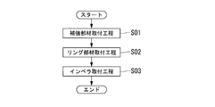
図9に示すように、まず、補強部材53をリング部材55に取り付ける補強部材取付工程(ステップS01)を行う。ここで、補強部材53がCFRPである場合は、強化材として用いられる炭素繊維が周方向を向くものが含まれるようにして、所定張力をかけた状態でリング部材55に巻き付ける。
図9に示すように、まず、補強部材53をリング部材55に取り付ける補強部材取付工程(ステップS01)を行う。ここで、補強部材53がCFRPである場合は、強化材として用いられる炭素繊維が周方向を向くものが含まれるようにして、所定張力をかけた状態でリング部材55に巻き付ける。
次いで、補強部材53が取り付けられたリング部材55を取付部本体54に取り付けるリング部材取付工程(ステップS02)を行う。この際、リング部材55は、冷し嵌め、焼嵌め等により取付部本体54に固定される。第一実施形態と同様に、補強部材53がCFRPである場合には、焼嵌めを行う際に、リング部材55を加熱してCFRPが100℃以下の状態で取り付ける。
さらに、リング部材55が取り付けられたインペラ210を回転軸5に対して、冷し嵌め、焼嵌め等による嵌め合いにより固定するインペラ取付工程(ステップS03)を行う。
さらに、リング部材55が取り付けられたインペラ210を回転軸5に対して、冷し嵌め、焼嵌め等による嵌め合いにより固定するインペラ取付工程(ステップS03)を行う。
上述した第二実施形態においては、補強部材53を、リング部材55の収容溝部55aに収容する場合を一例に説明した。しかし、リング部材55に収容溝部55aを設けずにリング部材55の外周に補強部材53を所定張力で巻き付けることで、補強部材53をリング部材55に取り付けるようにしても良い。
したがって、上述した第二実施形態のインペラ210によれば、リング部材55を取付部本体54の線膨張率以上の線膨張率を有する材料により形成することで、リング部材55を加熱して取付部本体54から取り外す際に、取付部本体54とリング部材55との温度差がより小さい状態で、リング部材55を取付部本体54から取り外すことができる。
その結果、温度上昇による補強部材53の熱的負荷を抑制しつつ補強部材53を取付部本体54から容易に取り外すことができる。
その結果、温度上昇による補強部材53の熱的負荷を抑制しつつ補強部材53を取付部本体54から容易に取り外すことができる。
また、補強部材53をリング部材55に取り付けた後に、リング部材55を筒部32に取り付けることで、補強部材53を取付部本体54に取り付けることができる。そのため、補強部材53を取付部本体54に対して容易に装着することができる。
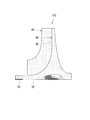
次に、この発明の第三実施形態におけるインペラ310を図面に基づき説明する。なお、この第三実施形態のインペラ310は、上述した第二実施形態のインペラ210に対して、グリップ部33の構成が異なるだけである。そのため、上述した第二実施形態と同一部分には同一符号を付して説明し、詳細説明を省略する。
図10に示すように、この第三実施形態のインペラ310は、上述した第二実施形態のインペラ210と同様に、ディスク部30とブレード部40とを有するオープン型のインペラである。ディスク部30は、ディスク本体部35と、筒部32と、を備えている。
上述した第二実施形態と同様に、筒部32は、ディスク本体部35よりも軸線O方向の後方側に、筒部32の一部を構成する円筒状の補強部材取付部250を備えている。
補強部材取付部250は、取付部本体54とリング部材55とを備えている。補強部材取付部250には、補強部材53が外側から覆うように取り付けられている。
上述した第二実施形態と同様に、筒部32は、ディスク本体部35よりも軸線O方向の後方側に、筒部32の一部を構成する円筒状の補強部材取付部250を備えている。
補強部材取付部250は、取付部本体54とリング部材55とを備えている。補強部材取付部250には、補強部材53が外側から覆うように取り付けられている。
筒部32は、回転軸5の外周面に固定されるグリップ部33を備えている。このグリップ部33は、ディスク本体部35よりも軸線O方向の後方側に配されている。より具体的には、グリップ部33は、補強部材取付部50よりも軸線O方向で後方側に配されている。筒部32は、軸線方向の第一方向側となる前方側に、非グリップ部34を備えている。
筒部32には、グリップ押え部材56が取り付けられている。このグリップ押え部材56は、グリップ部33を径方向外側から押さえることでグリップ部33における筒部32を補強する。グリップ押え部材56は、その軸線O方向における長さが、グリップ部33の長さよりも十分に短く形成されている。グリップ押え部材56は、筒部32のグリップ部33が配される位置に取り付けられている。より具体的には、グリップ押え部材56は、グリップ部33の最も前方側の位置に取り付けられている。
グリップ押え部材56は、グリップリング部材57とグリップ補強部材58とを備えている。グリップリング部材57は、上述したリング部材55と同様の材料により形成され、筒部32に取り付けられていない状態で、その内径が、被取り付け箇所の筒部32の外径よりも僅かに小さく形成されている。さらに、グリップリング部材57には、上述した収容溝部55aと同様に、リング状の収容溝部59が形成されている。収容溝部59には、上述した補強部材53と同様の材料により形成された円筒状のグリップ補強部材58が収容されている。
図11に示すように、グリップ押え部材56は、上述したリング部材55を取付部本体54に取り付けた後に、上述したリング部材55と同様に、冷し嵌めや焼嵌めで筒部32に取り付けられる。この実施形態においては、上記グリップ押え部材56がグリップリング部材57を備える場合について説明したが、グリップリング部材57を省略してグリップ補強部材58を筒部32に直接取り付けるようにしても良い。図10、図11中、リング部材55の内径と、グリップリング部材57の外径とが同等となっているが、グリップリング部材57の径方向の厚さは図10、図11の厚さに限られず、筒部32の強度や剛性に応じて最適な厚さに設定される。例えば、リング部材55の内径よりも、グリップリング部材57の外径が小さい場合には、グリップリング部材57を筒部32に装着した後に、リング部材55を取付部本体54に取り付けるようにしても良い。
したがって、上述した第三実施形態のインペラ310によれば、グリップ補強部材58によって、遠心力に起因するグリップ部33の径方向外側への変形を規制することができる。そのため、グリップ部33近傍の筒部32にかかるフープ応力の低減を図ると同時に、回転軸5に対してインペラ310をより強固に固定することができる。
この発明は上述した各実施形態の構成に限られるものではなく、その要旨を逸脱しない範囲で設計変更可能である。
例えば、上述した各実施形態では、ディスク部30とブレード部40のみを有するオープン型インペラを例に説明したが、この発明はこの場合に限定されない。ディスク部30とブレード部40に対して更にカバー部を有するクローズ型インペラにおいても同様に適用できる。
例えば、上述した各実施形態では、ディスク部30とブレード部40のみを有するオープン型インペラを例に説明したが、この発明はこの場合に限定されない。ディスク部30とブレード部40に対して更にカバー部を有するクローズ型インペラにおいても同様に適用できる。
更に、上述した各実施形態では、回転機械として遠心圧縮機100の一例を説明したが、遠心圧縮機100に限られず、例えば、各種産業用圧縮機やターボ冷凍機、小型ガスタービンにもこの発明のインペラを適用可能である。
この発明によれば、回転軸に対して容易に着脱可能であると共に回転時のフープ応力を十分に低減可能であり、更なる高速回転が可能となる。
5 回転軸
10 インペラ
30 ディスク部
31 前側面
31a 曲面
32 筒部
32a 外周面
33 グリップ部
34 非グリップ部
35 ディスク本体部
40 ブレード部
40a 面
50 補強部材取付部
51 後側面
53 補強部材
54 取付部本体
55 リング部材
55a 収容溝部
56 グリップ押え部材
57 グリップリング部材
58 グリップ補強部材
59 収容溝部
100 遠心圧縮機
104 流路
105 ケーシング
105a ジャーナル軸受
105b スラスト軸受
105c 吸込口
105d 排出口
105e 壁面
210 インペラ
250 補強部材取付部
310 インペラ
610 インペラ
710 インペラ
a1 上限値
a2 上限値
D 直径
G ガス
O 軸線
r1 外径
r2 直径
Claims (7)
- 軸線回りに回動される回転軸が挿通され、前記回転軸の軸線方向の一部がグリップ部として前記回転軸に固定される筒部と、前記筒部から前記回転軸の径方向外側に向かって延びるディスク本体部と、を備えたディスク部と、
前記ディスク本体部から軸線方向の第一方向側に突出するブレードと、
前記ディスク本体部よりも前記軸線方向の第二方向側の前記筒部に形成される補強部材取付部と、
前記ディスク部よりも比強度の高い材料により形成され、前記補強部材取付部を外側から覆うように取付られる補強部材と、を備えるインペラ。 - 前記補強部材取付部は、
前記筒部と一体に形成される取付部本体と、
前記取付部本体の線膨張率以上の線膨張率を有する材料により形成され、前記取付部本体に取り付けられるリング部材と、を備え、
前記補強部材は、前記リング部材に取り付けられている請求項1に記載のインペラ。 - 前記補強部材よりも前記軸線方向の第二方向側に前記グリップ部が配され、前記筒部の前記グリップ部が配される位置に取付られて前記グリップ部を補強するグリップ補強部材を備える請求項1又は2に記載のインペラ。
- 前記ディスク本体部の直径に対する前記補強部材の直径の比率が、0.35から0.8である請求項1から3の何れか一項に記載のインペラ。
- 請求項1から請求項4の何れか一項に記載のインペラを備える回転機械。
- 請求項1に記載のインペラを備える回転機械の組立方法であって、
前記補強部材を前記補強部材取付部に取り付ける取付工程と、
前記インペラを前記回転軸に取り付けるインペラ取付工程と、を備える回転機械の組立方法。 - 請求項2に記載のインペラを備える回転機械の組立方法であって、
前記補強部材を前記リング部材に取り付ける補強部材取付工程と、
前記補強部材が取り付けられた前記リング部材を前記取付部本体に取り付けるリング部材取付工程と、
前記インペラを前記回転軸に取り付けるインペラ取付工程と、を備える回転機械の組立方法。
Priority Applications (3)
| Application Number | Priority Date | Filing Date | Title |
|---|---|---|---|
| EP14807357.0A EP2955386B1 (en) | 2013-06-04 | 2014-01-14 | Impeller and shaft assembly, rotating machine, and method for assembling rotating machine |
| US14/774,248 US10514045B2 (en) | 2013-06-04 | 2014-01-14 | Impeller, rotating machine, and method for assembling rotating machine |
| CN201480013679.6A CN105051373B (zh) | 2013-06-04 | 2014-01-14 | 叶轮、旋转机械及旋转机械的组装方法 |
Applications Claiming Priority (2)
| Application Number | Priority Date | Filing Date | Title |
|---|---|---|---|
| JP2013117596A JP6029541B2 (ja) | 2013-06-04 | 2013-06-04 | インペラ、回転機械、および、回転機械の組立方法 |
| JP2013-117596 | 2013-06-04 |
Publications (1)
| Publication Number | Publication Date |
|---|---|
| WO2014196214A1 true WO2014196214A1 (ja) | 2014-12-11 |
Family
ID=52007871
Family Applications (1)
| Application Number | Title | Priority Date | Filing Date |
|---|---|---|---|
| PCT/JP2014/050444 WO2014196214A1 (ja) | 2013-06-04 | 2014-01-14 | インペラ、回転機械、および、回転機械の組立方法 |
Country Status (5)
| Country | Link |
|---|---|
| US (1) | US10514045B2 (ja) |
| EP (1) | EP2955386B1 (ja) |
| JP (1) | JP6029541B2 (ja) |
| CN (1) | CN105051373B (ja) |
| WO (1) | WO2014196214A1 (ja) |
Families Citing this family (3)
| Publication number | Priority date | Publication date | Assignee | Title |
|---|---|---|---|---|
| KR101650459B1 (ko) * | 2014-12-22 | 2016-08-23 | 주식회사 포스코 | 급수펌프 수리 방법 |
| JP7333247B2 (ja) * | 2019-11-01 | 2023-08-24 | 三菱重工コンプレッサ株式会社 | アンモニアプラント合成ガス圧縮機トレイン |
| US20240117811A1 (en) * | 2022-10-07 | 2024-04-11 | Hamilton Sundstrand Corporation | Impeller preloading bands |
Citations (5)
| Publication number | Priority date | Publication date | Assignee | Title |
|---|---|---|---|---|
| JPH08232889A (ja) * | 1994-12-19 | 1996-09-10 | Man B & W Diesel Gmbh | 流体機械のランナ |
| JP3129587B2 (ja) * | 1993-08-23 | 2001-01-31 | 石川島播磨重工業株式会社 | 遠心式低温圧縮機のインペラ取付構造 |
| JP2005002849A (ja) | 2003-06-11 | 2005-01-06 | Komatsu Ltd | コンプレッサインペラ及びこれを用いたターボチャージャ |
| JP2006214341A (ja) * | 2005-02-03 | 2006-08-17 | Shimadzu Corp | ターボ型回転機器 |
| JP2012122398A (ja) * | 2010-12-08 | 2012-06-28 | Mitsubishi Heavy Ind Ltd | 回転機械 |
Family Cites Families (7)
| Publication number | Priority date | Publication date | Assignee | Title |
|---|---|---|---|---|
| US5163816A (en) * | 1991-07-12 | 1992-11-17 | General Motors Corporation | Wheel lock, centering and drive means and turbocharger impeller combination |
| DE4321173C2 (de) * | 1993-06-25 | 1996-02-22 | Inst Luft Kaeltetech Gem Gmbh | Radiallaufrad |
| JP4946114B2 (ja) | 2006-03-20 | 2012-06-06 | 株式会社Ihi | 回転機械 |
| JP2009167882A (ja) * | 2008-01-15 | 2009-07-30 | Toyota Motor Corp | 遠心羽根車 |
| JP2009264205A (ja) | 2008-04-24 | 2009-11-12 | Hitachi Plant Technologies Ltd | 遠心圧縮機 |
| JP2011085088A (ja) | 2009-10-16 | 2011-04-28 | Mitsubishi Heavy Ind Ltd | 遠心圧縮機のインペラーとその設計方法 |
| IT1397328B1 (it) * | 2009-12-11 | 2013-01-10 | Nuovo Pignone Spa | Anelli compositi per montaggio girante-albero. |
-
2013
- 2013-06-04 JP JP2013117596A patent/JP6029541B2/ja active Active
-
2014
- 2014-01-14 EP EP14807357.0A patent/EP2955386B1/en active Active
- 2014-01-14 WO PCT/JP2014/050444 patent/WO2014196214A1/ja active Application Filing
- 2014-01-14 CN CN201480013679.6A patent/CN105051373B/zh not_active Expired - Fee Related
- 2014-01-14 US US14/774,248 patent/US10514045B2/en active Active
Patent Citations (5)
| Publication number | Priority date | Publication date | Assignee | Title |
|---|---|---|---|---|
| JP3129587B2 (ja) * | 1993-08-23 | 2001-01-31 | 石川島播磨重工業株式会社 | 遠心式低温圧縮機のインペラ取付構造 |
| JPH08232889A (ja) * | 1994-12-19 | 1996-09-10 | Man B & W Diesel Gmbh | 流体機械のランナ |
| JP2005002849A (ja) | 2003-06-11 | 2005-01-06 | Komatsu Ltd | コンプレッサインペラ及びこれを用いたターボチャージャ |
| JP2006214341A (ja) * | 2005-02-03 | 2006-08-17 | Shimadzu Corp | ターボ型回転機器 |
| JP2012122398A (ja) * | 2010-12-08 | 2012-06-28 | Mitsubishi Heavy Ind Ltd | 回転機械 |
Also Published As
| Publication number | Publication date |
|---|---|
| CN105051373B (zh) | 2017-05-17 |
| EP2955386B1 (en) | 2019-05-15 |
| EP2955386A1 (en) | 2015-12-16 |
| EP2955386A4 (en) | 2016-03-02 |
| JP2014234786A (ja) | 2014-12-15 |
| CN105051373A (zh) | 2015-11-11 |
| JP6029541B2 (ja) | 2016-11-24 |
| US20160040687A1 (en) | 2016-02-11 |
| US10514045B2 (en) | 2019-12-24 |
Similar Documents
| Publication | Publication Date | Title |
|---|---|---|
| JP5145117B2 (ja) | 圧縮機のハウジング | |
| JP6124787B2 (ja) | ロータブレード用の軽量シュラウド | |
| US9347460B2 (en) | Rotary machine | |
| JP5613764B2 (ja) | ターボ機械用羽根車 | |
| JP5511852B2 (ja) | ロータ組立体 | |
| WO2014196214A1 (ja) | インペラ、回転機械、および、回転機械の組立方法 | |
| US11073020B2 (en) | Impeller and rotating machine provided with same | |
| JP6327505B2 (ja) | インペラ及び回転機械 | |
| JP5370046B2 (ja) | 航空機エンジン用ファン | |
| JP2009167882A (ja) | 遠心羽根車 | |
| US10961853B2 (en) | Spigot assembly for rotating components | |
| JP6047091B2 (ja) | ロータ及び真空ポンプ | |
| JP2010185409A (ja) | タービン発電機コレクタファン及びその製造方法 | |
| JP3144272U (ja) | ターボ分子ポンプ | |
| JP2012052439A (ja) | インペラ | |
| JP2013147984A (ja) | インペラ、および回転機械 | |
| WO2020049810A1 (ja) | 遠心羽根車および遠心式流体機械 | |
| JP5905517B2 (ja) | インペラ | |
| JP2018096363A (ja) | タービン翼、タービン機器およびタービン | |
| JP2015227627A (ja) | 回転機械 | |
| JP2018003670A (ja) | ターボ機械 | |
| CN115199585A (zh) | 叶轮及制造这种叶轮的方法 | |
| JP2014169705A (ja) | インペラ |
Legal Events
| Date | Code | Title | Description |
|---|---|---|---|
| WWE | Wipo information: entry into national phase |
Ref document number: 201480013679.6 Country of ref document: CN |
|
| 121 | Ep: the epo has been informed by wipo that ep was designated in this application |
Ref document number: 14807357 Country of ref document: EP Kind code of ref document: A1 |
|
| WWE | Wipo information: entry into national phase |
Ref document number: 14774248 Country of ref document: US Ref document number: 2014807357 Country of ref document: EP |
|
| NENP | Non-entry into the national phase |
Ref country code: DE |