WO2014192830A1 - 化学・物理現象検出方法及びその装置 - Google Patents
化学・物理現象検出方法及びその装置 Download PDFInfo
- Publication number
- WO2014192830A1 WO2014192830A1 PCT/JP2014/064177 JP2014064177W WO2014192830A1 WO 2014192830 A1 WO2014192830 A1 WO 2014192830A1 JP 2014064177 W JP2014064177 W JP 2014064177W WO 2014192830 A1 WO2014192830 A1 WO 2014192830A1
- Authority
- WO
- WIPO (PCT)
- Prior art keywords
- sensing unit
- microparticles
- recess
- detection method
- detection
- Prior art date
- Legal status (The legal status is an assumption and is not a legal conclusion. Google has not performed a legal analysis and makes no representation as to the accuracy of the status listed.)
- Ceased
Links
Images

Classifications
-
- G—PHYSICS
- G01—MEASURING; TESTING
- G01N—INVESTIGATING OR ANALYSING MATERIALS BY DETERMINING THEIR CHEMICAL OR PHYSICAL PROPERTIES
- G01N27/00—Investigating or analysing materials by the use of electric, electrochemical, or magnetic means
- G01N27/26—Investigating or analysing materials by the use of electric, electrochemical, or magnetic means by investigating electrochemical variables; by using electrolysis or electrophoresis
- G01N27/403—Cells and electrode assemblies
- G01N27/414—Ion-sensitive or chemical field-effect transistors, i.e. ISFETS or CHEMFETS
- G01N27/4145—Ion-sensitive or chemical field-effect transistors, i.e. ISFETS or CHEMFETS specially adapted for biomolecules, e.g. gate electrode with immobilised receptors
-
- B—PERFORMING OPERATIONS; TRANSPORTING
- B01—PHYSICAL OR CHEMICAL PROCESSES OR APPARATUS IN GENERAL
- B01L—CHEMICAL OR PHYSICAL LABORATORY APPARATUS FOR GENERAL USE
- B01L3/00—Containers or dishes for laboratory use, e.g. laboratory glassware; Droppers
- B01L3/50—Containers for the purpose of retaining a material to be analysed, e.g. test tubes
- B01L3/502—Containers for the purpose of retaining a material to be analysed, e.g. test tubes with fluid transport, e.g. in multi-compartment structures
- B01L3/5027—Containers for the purpose of retaining a material to be analysed, e.g. test tubes with fluid transport, e.g. in multi-compartment structures by integrated microfluidic structures, i.e. dimensions of channels and chambers are such that surface tension forces are important, e.g. lab-on-a-chip
- B01L3/502761—Containers for the purpose of retaining a material to be analysed, e.g. test tubes with fluid transport, e.g. in multi-compartment structures by integrated microfluidic structures, i.e. dimensions of channels and chambers are such that surface tension forces are important, e.g. lab-on-a-chip specially adapted for handling suspended solids or molecules independently from the bulk fluid flow, e.g. for trapping or sorting beads, for physically stretching molecules
-
- G—PHYSICS
- G01—MEASURING; TESTING
- G01N—INVESTIGATING OR ANALYSING MATERIALS BY DETERMINING THEIR CHEMICAL OR PHYSICAL PROPERTIES
- G01N33/00—Investigating or analysing materials by specific methods not covered by groups G01N1/00 - G01N31/00
- G01N33/48—Biological material, e.g. blood, urine; Haemocytometers
- G01N33/50—Chemical analysis of biological material, e.g. blood, urine; Testing involving biospecific ligand binding methods; Immunological testing
- G01N33/53—Immunoassay; Biospecific binding assay; Materials therefor
- G01N33/543—Immunoassay; Biospecific binding assay; Materials therefor with an insoluble carrier for immobilising immunochemicals
- G01N33/54313—Immunoassay; Biospecific binding assay; Materials therefor with an insoluble carrier for immobilising immunochemicals the carrier being characterised by its particulate form
- G01N33/54326—Magnetic particles
-
- G—PHYSICS
- G01—MEASURING; TESTING
- G01N—INVESTIGATING OR ANALYSING MATERIALS BY DETERMINING THEIR CHEMICAL OR PHYSICAL PROPERTIES
- G01N33/00—Investigating or analysing materials by specific methods not covered by groups G01N1/00 - G01N31/00
- G01N33/48—Biological material, e.g. blood, urine; Haemocytometers
- G01N33/50—Chemical analysis of biological material, e.g. blood, urine; Testing involving biospecific ligand binding methods; Immunological testing
- G01N33/53—Immunoassay; Biospecific binding assay; Materials therefor
- G01N33/543—Immunoassay; Biospecific binding assay; Materials therefor with an insoluble carrier for immobilising immunochemicals
- G01N33/54366—Apparatus specially adapted for solid-phase testing
- G01N33/54373—Apparatus specially adapted for solid-phase testing involving physiochemical end-point determination, e.g. wave-guides, FETS, gratings
-
- B—PERFORMING OPERATIONS; TRANSPORTING
- B01—PHYSICAL OR CHEMICAL PROCESSES OR APPARATUS IN GENERAL
- B01L—CHEMICAL OR PHYSICAL LABORATORY APPARATUS FOR GENERAL USE
- B01L2200/00—Solutions for specific problems relating to chemical or physical laboratory apparatus
- B01L2200/06—Fluid handling related problems
- B01L2200/0647—Handling flowable solids, e.g. microscopic beads, cells, particles
- B01L2200/0668—Trapping microscopic beads
-
- B—PERFORMING OPERATIONS; TRANSPORTING
- B01—PHYSICAL OR CHEMICAL PROCESSES OR APPARATUS IN GENERAL
- B01L—CHEMICAL OR PHYSICAL LABORATORY APPARATUS FOR GENERAL USE
- B01L2300/00—Additional constructional details
- B01L2300/06—Auxiliary integrated devices, integrated components
- B01L2300/0627—Sensor or part of a sensor is integrated
- B01L2300/0645—Electrodes
-
- B—PERFORMING OPERATIONS; TRANSPORTING
- B01—PHYSICAL OR CHEMICAL PROCESSES OR APPARATUS IN GENERAL
- B01L—CHEMICAL OR PHYSICAL LABORATORY APPARATUS FOR GENERAL USE
- B01L2300/00—Additional constructional details
- B01L2300/08—Geometry, shape and general structure
- B01L2300/0809—Geometry, shape and general structure rectangular shaped
- B01L2300/0819—Microarrays; Biochips
-
- B—PERFORMING OPERATIONS; TRANSPORTING
- B01—PHYSICAL OR CHEMICAL PROCESSES OR APPARATUS IN GENERAL
- B01L—CHEMICAL OR PHYSICAL LABORATORY APPARATUS FOR GENERAL USE
- B01L2300/00—Additional constructional details
- B01L2300/08—Geometry, shape and general structure
- B01L2300/0848—Specific forms of parts of containers
- B01L2300/0851—Bottom walls
-
- B—PERFORMING OPERATIONS; TRANSPORTING
- B01—PHYSICAL OR CHEMICAL PROCESSES OR APPARATUS IN GENERAL
- B01L—CHEMICAL OR PHYSICAL LABORATORY APPARATUS FOR GENERAL USE
- B01L2300/00—Additional constructional details
- B01L2300/08—Geometry, shape and general structure
- B01L2300/0893—Geometry, shape and general structure having a very large number of wells, microfabricated wells
Definitions
- the present invention relates to a chemical / physical phenomenon detection method and improvement of the apparatus.
- a cumulative chemical / physical phenomenon detection device described in Patent Document 1 is known.
- the potential change of the sensing unit when the sample is brought into contact with the sensing unit is converted into a change in the amount of charge, and the change in the amount of charge is accumulated in the floating diffusion unit to detect a highly sensitive ion concentration.
- the sensing unit of this detection device has a structure in which a silicon nitride film (ion sensitive film) is laminated on a silicon substrate via a silicon oxide film (insulating film).
- sensing is performed to convert this potential change into a change in charge.
- a charge supply (ID) part, a charge injection control (ICG) part, a gate (TG) part, and a floating diffusion (FD) part are attached around the part. Because of these electrode materials, the periphery of the sensing part is raised, in other words, the sensing part is present on the bottom surface of the recess.
- ISFET ion-sensitive field effect semiconductor sensor
- the detection target In order to measure the chemical phenomenon or physical phenomenon of the detection target contained in the sample or those phenomena caused by the detection target with higher sensitivity, the detection target must be brought into contact with or close to the sensing unit. However, depending on the detection target, it may be difficult to stably contact or approach the sensing unit. For example, when the material of the detection target and the material of the sensing unit are chemically repelled, or when the detection target is fine and lightweight and affected by the molecular motion of the surroundings (dispersion medium, etc.), in these cases, The action of the detection target on the sensing unit becomes unstable.
- the opening area of the recess becomes very small, so that the sensing object can be stabilized to the sensing part located on the bottom surface. Thus, it becomes more difficult to make contact or proximity.
- one of the molecules (for example, antibody) is used in the sensing part.
- the sensing unit may not respond to it.
- the antibody is longer than the Debye length of the sensing unit, there is a possibility that no potential change occurs in the ion exchange membrane even if an antigen is bound to the antibody.
- the first aspect of the present invention solves at least one of the above-described problems, and is defined as follows. That is, A chemical / physical phenomenon detection method for measuring a potential change of the sensing unit by bringing a detection target into contact with or in proximity to the sensing unit, A chemical / physical phenomenon detection method for measuring a potential change of the sensing unit in a state in which the fine particles captured by the detection target are fixed to the sensing unit.
- the detection target is trapped by the microparticles, and thus the detection target cannot be stably brought into contact with and close to the sensing unit by itself.
- the detection method according to the first aspect includes a filling step in which the sensing portion is present on the bottom surface of the recess in the sensor surface, and the microparticles are filled into the recess.
- a force that is, an acceleration so that the fine particles approach the bottom surface of the recess, that is, the sensing unit (third aspect).
- the method of applying acceleration to the fine particles is not particularly limited, such as the use of gravity, the use of centrifugal force, the use of magnetic force, etc., but it is an apparatus that uses the magnetic force by forming the fine particles with a magnetic material. This is preferable from the viewpoint of simplifying the configuration (fourth aspect). If a force in the direction of the bottom of the recess, that is, the sensing portion is applied to the microparticles, the microparticles may be stacked on the peripheral wall surface of the recess.
- the microparticles stacked on the surface of the peripheral wall interfere with the microparticles to be filled in the recess and prevent the microparticles from being filled in the recess.
- the recesses may be filled with the microparticles and overflow from there. It is preferable to remove such extra fine particles from the sensor surface of the sensor chip (fifth aspect).
- the removal method is not particularly limited, but can be performed by scraping the sensor surface with a blade or the like.
- the microparticles filled in the recess are separated from the recess.
- a force (gravity, centrifugal force, magnetic force, etc.) is applied to the microparticles in a direction away from the sensing unit.
- a magnet is disposed above the opening of the recess to suck out the fine particles from the recess.
- a force is applied after breaking the chemical bonds.
- the method of decomposing the chemical bond is not particularly limited, but by adding an acid, alkali or enzyme that decomposes the detection target itself.
- the detection target is not particularly limited as long as the detection target is captured by the microparticles and acts on the sensing unit directly or indirectly to change the potential of the sensing unit.
- the detection target reflects the chemical characteristics and physical characteristics of the sample. For example, when an ion species is selected as the detection target, the ion concentration of the detection target is specified by measuring the amount.
- the antigen when one molecule (for example, antigen) of a pair of molecules constituting an intermolecular interaction is to be detected, the antigen itself becomes an ionic species or itself chemically changes to generate an ionic species. Or react with other drugs to produce ionic species.
- detection targets include (1) virus, bacteria, parasites, protozoa (malaria, etc.) pathogens, (2) cancer cells, iPS cells, leukocytes, eggs, sperm, stem cells (bone marrow, nerves, etc.) ) Cells, (3) enzymes, cytokines, hormones (insulin, etc.), snake venom, proteins / peptides such as A ⁇ 40, (4) nucleic acids such as DNA, mRNA, miRNA, (5) synthetic compounds, drugs, nucleic acid metabolites (8OHdG etc.), amino acid metabolites, lipid metabolites, sugar metabolites, natural compounds, vitamins, toxins (tetrodotoxin etc.) compounds, (6) mercury, lead, zinc, chromium, cobalt, gold, cadmium, tin, palladium And metals such as amalgam.
- virus bacteria, parasites, protozoa (malaria, etc.) pathogens
- cancer cells iPS cells, leukocytes, eggs,
- exosomes When exosomes are used as detection targets, antibodies that capture exosomes themselves can be planted in microparticles, and DNA that hybridizes with miRNA released from degraded exosomes can be planted in microparticles. preferable. When this DNA binds to miRNA, miRNA is also detected. Since exosomes are captured in the vicinity of DAN by microparticles, high detection sensitivity for exosome-derived miRNA can be achieved.
- the capsule (the exosome) containing the detection target is captured by the first capturing body (the exosome antibody) bound to the microparticle, and the capsule Is released, and the detection target contained therein is released, and then captured by a second capturing body (same as that of DNA) bound to the microparticles.
- the capsule in the sample solution is captured by the first capturing body of the fine particles and concentrated in the sample solution.
- the detection target released from the capsule thus concentrated is also captured by the second capture body that is coupled to the microparticles (that is, present in the vicinity of the capsule).
- the detection target can be detected with high sensitivity.
- the detection device is not particularly limited as long as the detection device includes a sensing unit that can temporarily or permanently fix the microparticles.
- the effect of using the microparticles becomes significant. This is because it is difficult to selectively plant one of the molecular pairs constituting the intermolecular interaction (for example, an antibody) on the bottom surface of the recess.
- this type of detection device there are a CCD type and an ISFET type disclosed in Patent Document 1.
- the material, shape, size, and capturing method of the microparticles are appropriately selected according to the detection target and the sensing unit.
- the material of the microparticles may be any material that is stable with respect to the sample, and inorganic materials such as metals and ceramics, organic materials such as plastics, or hybrid materials thereof can be used.
- a magnetic field a magnetic material such as iron that can be moved under the influence of an external magnetic field is used.
- the shape of the fine particles is preferably spherical or elliptical from the viewpoint of securing a surface area and reducing interference between the fine particles.
- the fine particles may be primary particles, secondary particles obtained by aggregating them, or other multi-particles.
- the size (diameter) of the fine particles is sufficiently larger than the detection target to be captured.
- one of the molecular pairs is implanted in the microparticle, so that the microparticle is sufficiently larger than the antibody.
- a sensing part exists in the bottom face of a recess, it makes it sufficiently smaller than the opening part of a recess.
- the method of capturing the detection target by the microparticles can be arbitrarily selected according to the characteristics of the detection target. As described above, when the detection target is an antigen, it can be indirectly captured via an antibody on the surface of the microparticle.
- the surface of the microparticle can be chemically modified, and the microparticle can be captured by a method such as inclusion or chelation. Furthermore, a physical capturing method such as providing fine pores in the microparticles and adsorbing the detection target to the fine pores can also be adopted.
- the timing at which such a microparticle captures the detection target can be arbitrarily selected.
- the detection target can be captured in advance by a fine particle and then fixed to the sensing unit, or the fine particle can be fixed in advance to the sensing unit and contacted with the sample to form a fine particle.
- the detection target may be captured by the body.
- “fixed” refers to a state in which the position of the microparticle does not vary with respect to the sensing unit. In other words, “fixed” in this specification refers to a state in which no potential change is caused in the sensing unit due to a change in position of the microparticles themselves.
- FIG. 1 shows the basic configuration of a chemical / physical phenomenon detection apparatus according to an embodiment of the present invention.
- This detection device has the same principle structure as the detection device described in Patent Document 1, and as shown in FIG. 1, n + -type doped regions 11 and 13 and a p-type doped region 15 are formed on a silicon substrate 10.
- a silicon oxide film 19 is stacked in the p-type doped region 15 as a gate insulating film.
- Two gate electrodes 22 and 24 are provided on the silicon oxide film 19.
- the upper side surface is a sensor surface, and the portion of the ion sensitive film 23 in contact with the silicon oxide film 19 becomes the sensing unit 3. Needless to say, the potential of the sample is kept constant by a reference electrode (not shown).
- Reference numeral 23 in the figure denotes an ion sensitive film, and a silicon nitride film is adopted when amyloid protein A ⁇ 40 as an ionic species is to be detected.
- the n + region 11, the first gate electrode 22, the second gate electrode 24, and the n + region 13 of the substrate are connected to the terminals ID, ICG, TG, and FD, respectively, and a predetermined potential is applied at a predetermined timing.
- the n + region 11 of the substrate serves as the charge supply unit 1
- the part corresponding to the first gate electrode 22 serves as the charge injection control unit 2
- the part corresponding to the ion sensitive film 23 serves as the sensing unit 3.
- the portion corresponding to the gate electrode 24 becomes the barrier portion 4, and the n + -type region 13 becomes the floating diffusion portion 5.
- FIG. 2 shows a sensor chip in which the detection device 1 (element) shown in FIG. 1 is integrated.
- the sensor surface of the element is integrated in the central rectangular portion that occupies the widest area, and becomes the sensor surface of the sensor chip.
- the gate electrodes 22 and 24 exist as shown in FIG. 1, it turns out that the sensing part 3 exists in the bottom face of a recess in the upper surface of an element.
- a control wiring is attached in addition to the gate electrode, so that the periphery of the sensing unit 3 is surrounded by a wall. More specifically, in the sensor chip of FIG.
- the sensing unit 3 is a rectangle of 13.5 ⁇ m ⁇ 24.5 ⁇ m, and the height of the surrounding wall is 3.0 ⁇ m. is there.
- the surface of the wall around the sensing unit 3 is exposed by the same ion sensitive film 23 as the sensing unit 3.
- an anti-A ⁇ antibody is selectively placed on the sensing unit 3 on the bottom surface of a micron order and is fixed (planted). ), But no such method is known.
- general-purpose 6E10 is employed as the anti-amyloid protein A ⁇ 40 antibody, its molecular length is about 10 nm.
- the sensing unit 3 since the sensing unit 3 has a Debye length (sensitive area) of 10 to 20 nm due to the apparatus configuration, even if the antibody can be selectively planted on the surface of the sensing unit 3, it is captured by the antibody.
- the amyloid protein A ⁇ 40 exists outside the Debye length. Therefore, sufficient sensitivity for amyloid protein A ⁇ 40 cannot be ensured.
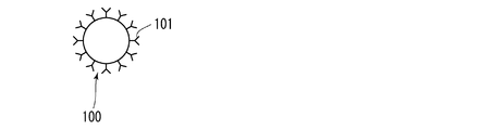
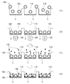
- the antibody 101 was implanted on the surface of the microparticle 100. Then, as shown in FIG. 4, the microparticles 100 were filled in the recesses 110 on the sensor surface. FG beads (manufactured by Tamagawa Seiki Co., Ltd .: particle size: about 0.2 ⁇ m) were used as the microparticles 100, and Covance (molecular length: about 10 nm) was used for the antibody 101 of the amyloid protein A ⁇ 40. . The antibody 101 was planted on the microparticles 100 as follows.
- a microparticle 100 having a carboxyl group on the surface as a linker (COOH amount: 100 to 200 nmol / mg) was added to ethyl (dimethylaminopropyl) carbodiimide as a coupling reagent and N-hydroxysuccinimide as an activating reagent for carboxylic acid ( NHS) is mixed to form an NHS body having an unstable ester bond.
- the antibody 101 is added thereto to react with the amino group of the antibody, and the antibody is implanted around the microparticle by an amide bond.
- the width of the wall section that divides the sensing section 3 of one element and the sensing section 3 of another element of the detection device 1 is 10 to 20 ⁇ m.
- the microparticles 100 in which the antibodies are planted are dispersed in water, and the sensor chip is immersed in this so that the sensing unit 3 faces upward (FIG. 4A).
- a magnet 120 residual magnetic flux density: 1.17 to 1.38 Tesla, size: 1 cm 3
- the microparticles 100 floating in water are attracted to the sensing unit 3 side (FIG. 4B).
- the magnet is drawn so as to be opposed to each element, but this is conceptually drawn as means for applying a magnetic field, and the sensor of FIG. 2 whose one side is less than 10 mm.
- the chip one magnet is disposed on the back surface of the sensor chip to apply a magnetic field to the microparticles.
- the sensor chip is immersed in the sample (FIG. 4C).
- This sample contains the amyloid protein A ⁇ 40 as the detection target 130, and this protein binds to the antibody 101 implanted in the microparticle 100. That is, it is indirectly captured by the microparticles 100.
- some of the antibodies 101 planted in the microparticles 100 face the surface of the sensing unit 3, so that the amyloid protein A ⁇ 40 bound thereto contacts the sensing unit 3 or within its Debye length.
- FIG. 4D Thereby, the sensitivity with respect to amyloid protein A (beta) 40 improves.
- the sensor chip is operated in the state shown in FIG. 4D. The output from each element integrated in the sensor chip was added to obtain the output of the sensor chip.
- the concentration of amyloid protein A ⁇ 40 in the sample can be specified more accurately by statistically processing the output from each element.
- the sample is taken out from the sample or immersed in pure water, and a magnetic field is applied so that the microparticles 100 are separated from the sensing unit 3 (the previously used magnet is moved closer to the upper surface of the sensor chip). Thereby, the microparticles 100 are removed from the recess 110.
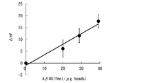
- FIG. 5 shows the output of the sensor chip obtained when the microparticles 100 having different amyloid protein A ⁇ 40 binding amounts are prepared and the above method is executed.
- the vertical axis represents the output of the sensor chip
- the horizontal axis represents the amount of amyloid protein A ⁇ 40 bound.
- Sensing unit 100 microparticles 101, antibody 110 recess, 130 detection target
Landscapes
- Health & Medical Sciences (AREA)
- Life Sciences & Earth Sciences (AREA)
- Immunology (AREA)
- Chemical & Material Sciences (AREA)
- Engineering & Computer Science (AREA)
- Molecular Biology (AREA)
- Hematology (AREA)
- Physics & Mathematics (AREA)
- Urology & Nephrology (AREA)
- Biomedical Technology (AREA)
- Analytical Chemistry (AREA)
- General Health & Medical Sciences (AREA)
- Biochemistry (AREA)
- General Physics & Mathematics (AREA)
- Pathology (AREA)
- Microbiology (AREA)
- Food Science & Technology (AREA)
- Medicinal Chemistry (AREA)
- Cell Biology (AREA)
- Biotechnology (AREA)
- Chemical Kinetics & Catalysis (AREA)
- Clinical Laboratory Science (AREA)
- Dispersion Chemistry (AREA)
- Fluid Mechanics (AREA)
- Spectroscopy & Molecular Physics (AREA)
- Microelectronics & Electronic Packaging (AREA)
- Electrochemistry (AREA)
- Investigating Or Analyzing Materials By The Use Of Magnetic Means (AREA)
Applications Claiming Priority (2)
| Application Number | Priority Date | Filing Date | Title |
|---|---|---|---|
| JP2013112444A JP2014232032A (ja) | 2013-05-29 | 2013-05-29 | 化学・物理現象検出方法及びその装置 |
| JP2013-112444 | 2013-05-29 |
Publications (1)
| Publication Number | Publication Date |
|---|---|
| WO2014192830A1 true WO2014192830A1 (ja) | 2014-12-04 |
Family
ID=51988853
Family Applications (1)
| Application Number | Title | Priority Date | Filing Date |
|---|---|---|---|
| PCT/JP2014/064177 Ceased WO2014192830A1 (ja) | 2013-05-29 | 2014-05-28 | 化学・物理現象検出方法及びその装置 |
Country Status (2)
| Country | Link |
|---|---|
| JP (1) | JP2014232032A (enExample) |
| WO (1) | WO2014192830A1 (enExample) |
Families Citing this family (3)
| Publication number | Priority date | Publication date | Assignee | Title |
|---|---|---|---|---|
| WO2017033922A1 (ja) * | 2015-08-24 | 2017-03-02 | 国立大学法人 東京大学 | 電界効果トランジスタを用いた目的物質の検出方法 |
| JP7130223B2 (ja) * | 2017-10-18 | 2022-09-05 | 株式会社Provigate | 電荷の遷移差を利用した抗原抗体反応検出装置 |
| JP2020186971A (ja) * | 2019-05-13 | 2020-11-19 | アイシン精機株式会社 | 微小物質検出方法 |
Citations (4)
| Publication number | Priority date | Publication date | Assignee | Title |
|---|---|---|---|---|
| JP2010243299A (ja) * | 2009-04-03 | 2010-10-28 | Sharp Corp | バイオセンサ、電荷転送型センサおよび測定方法 |
| JP2012080873A (ja) * | 2010-09-17 | 2012-04-26 | Univ Of Tokyo | Dna塩基配列解析装置およびdna塩基配列解析方法 |
| WO2012107717A1 (en) * | 2011-02-07 | 2012-08-16 | Multi-Sense Technologies Limited | Microfluidics based assay device |
| JP2013050426A (ja) * | 2011-08-31 | 2013-03-14 | Chiba Univ | Fet型センサを用いたインフルエンザウイルスrnaの検出方法 |
Family Cites Families (6)
| Publication number | Priority date | Publication date | Assignee | Title |
|---|---|---|---|---|
| JP4010172B2 (ja) * | 2001-04-25 | 2007-11-21 | 株式会社ニコン | 有機分子検出素子、有機分子検出装置、および、有機分子検出方法 |
| JP2004361227A (ja) * | 2003-06-04 | 2004-12-24 | Tohoku Univ | アミロイドβ結合蛋白質の同定方法 |
| JP5188091B2 (ja) * | 2006-03-31 | 2013-04-24 | キヤノン株式会社 | センサ素子、ならびにこの素子を用いた磁性粒子の検出方法及び標的物質の検出方法 |
| US20110014719A1 (en) * | 2008-03-17 | 2011-01-20 | Koninklijke Philips Electronics N.V. | Cartridge for assays with magnetic particles |
| WO2011033046A1 (en) * | 2009-09-18 | 2011-03-24 | Probiodrug Ag | Novel assay for the detection of amyloid beta peptides |
| JP5517125B2 (ja) * | 2010-02-05 | 2014-06-11 | 国立大学法人 東京大学 | 細胞測定装置 |
-
2013
- 2013-05-29 JP JP2013112444A patent/JP2014232032A/ja active Pending
-
2014
- 2014-05-28 WO PCT/JP2014/064177 patent/WO2014192830A1/ja not_active Ceased
Patent Citations (4)
| Publication number | Priority date | Publication date | Assignee | Title |
|---|---|---|---|---|
| JP2010243299A (ja) * | 2009-04-03 | 2010-10-28 | Sharp Corp | バイオセンサ、電荷転送型センサおよび測定方法 |
| JP2012080873A (ja) * | 2010-09-17 | 2012-04-26 | Univ Of Tokyo | Dna塩基配列解析装置およびdna塩基配列解析方法 |
| WO2012107717A1 (en) * | 2011-02-07 | 2012-08-16 | Multi-Sense Technologies Limited | Microfluidics based assay device |
| JP2013050426A (ja) * | 2011-08-31 | 2013-03-14 | Chiba Univ | Fet型センサを用いたインフルエンザウイルスrnaの検出方法 |
Also Published As
| Publication number | Publication date |
|---|---|
| JP2014232032A (ja) | 2014-12-11 |
Similar Documents
| Publication | Publication Date | Title |
|---|---|---|
| JP6150171B2 (ja) | 標的検体を検出するための装置 | |
| JP5975220B2 (ja) | 生物学的流体標本を分析することを目的とするデバイスおよび分析するための方法 | |
| JP6389003B2 (ja) | 体液中の物質を検出するシステム及び方法 | |
| Gao et al. | Direct ultrasensitive electrical detection of prostate cancer biomarkers with CMOS-compatible n-and p-type silicon nanowire sensor arrays | |
| US20160290957A1 (en) | Nanoelectronic sensor pixel | |
| CN103119443B (zh) | 用于检测环境间接调节的装置和方法 | |
| JP4777159B2 (ja) | デュアルゲート型センサ | |
| CN105980581A (zh) | 电容传感器及使用方法 | |
| US20230094539A1 (en) | Diagnostic device and system | |
| US20140191294A1 (en) | Backside stimulated sensor with background current manipulation | |
| US11313828B2 (en) | Ultra-highly sensitive electrochemical biosensor using beads and method for manufacturing the same | |
| US8093667B2 (en) | Flexible gate electrode device for bio-sensing | |
| WO2014192830A1 (ja) | 化学・物理現象検出方法及びその装置 | |
| Vu et al. | Fabrication and application of a microfluidic‐embedded silicon nanowire biosensor chip | |
| CN110192096A (zh) | 生物体物质检测用设备和检测装置、离子电流的测定方法以及生物体物质的识别方法 | |
| Dorvel et al. | Effect of biointerfacing linker chemistries on the sensitivity of silicon nanowires for protein detection | |
| JP5424227B2 (ja) | 被検物質検知センサー | |
| JP4680587B2 (ja) | バイオセンサ、対象物測定方法、バイオセンサ用カートリッジ及び不織布 | |
| JP2010243299A (ja) | バイオセンサ、電荷転送型センサおよび測定方法 | |
| Zhang et al. | Estimation of the depletion layer thickness in silicon nanowire-based biosensors from attomolar-level biomolecular detection | |
| JP2009501930A (ja) | バイオセンサのためのセンサチップ | |
| CN110090675A (zh) | 微流控芯片及其检测方法、微全分析系统 | |
| JP5259011B2 (ja) | 電気化学カメラ様式の装置およびその装置の製造方法ならびにその使用方法 | |
| WO2017033922A1 (ja) | 電界効果トランジスタを用いた目的物質の検出方法 | |
| JP4856854B2 (ja) | 物質移動装置及び物質移動方法 |
Legal Events
| Date | Code | Title | Description |
|---|---|---|---|
| 121 | Ep: the epo has been informed by wipo that ep was designated in this application |
Ref document number: 14803754 Country of ref document: EP Kind code of ref document: A1 |
|
| DPE1 | Request for preliminary examination filed after expiration of 19th month from priority date (pct application filed from 20040101) | ||
| NENP | Non-entry into the national phase |
Ref country code: DE |
|
| 122 | Ep: pct application non-entry in european phase |
Ref document number: 14803754 Country of ref document: EP Kind code of ref document: A1 |