WO2014192530A1 - 引き波検出装置、レーダ装置、引き波検出方法、及び引き波検出プログラム - Google Patents
引き波検出装置、レーダ装置、引き波検出方法、及び引き波検出プログラム Download PDFInfo
- Publication number
- WO2014192530A1 WO2014192530A1 PCT/JP2014/062658 JP2014062658W WO2014192530A1 WO 2014192530 A1 WO2014192530 A1 WO 2014192530A1 JP 2014062658 W JP2014062658 W JP 2014062658W WO 2014192530 A1 WO2014192530 A1 WO 2014192530A1
- Authority
- WO
- WIPO (PCT)
- Prior art keywords
- wave
- wavefront
- velocity
- pair
- pulling
- Prior art date
- Legal status (The legal status is an assumption and is not a legal conclusion. Google has not performed a legal analysis and makes no representation as to the accuracy of the status listed.)
- Ceased
Links
Images







Classifications
-
- G—PHYSICS
- G01—MEASURING; TESTING
- G01S—RADIO DIRECTION-FINDING; RADIO NAVIGATION; DETERMINING DISTANCE OR VELOCITY BY USE OF RADIO WAVES; LOCATING OR PRESENCE-DETECTING BY USE OF THE REFLECTION OR RERADIATION OF RADIO WAVES; ANALOGOUS ARRANGEMENTS USING OTHER WAVES
- G01S13/00—Systems using the reflection or reradiation of radio waves, e.g. radar systems; Analogous systems using reflection or reradiation of waves whose nature or wavelength is irrelevant or unspecified
- G01S13/88—Radar or analogous systems specially adapted for specific applications
- G01S13/95—Radar or analogous systems specially adapted for specific applications for meteorological use
- G01S13/956—Radar or analogous systems specially adapted for specific applications for meteorological use mounted on ship or other platform
-
- B—PERFORMING OPERATIONS; TRANSPORTING
- B63—SHIPS OR OTHER WATERBORNE VESSELS; RELATED EQUIPMENT
- B63B—SHIPS OR OTHER WATERBORNE VESSELS; EQUIPMENT FOR SHIPPING
- B63B49/00—Arrangements of nautical instruments or navigational aids
-
- B—PERFORMING OPERATIONS; TRANSPORTING
- B63—SHIPS OR OTHER WATERBORNE VESSELS; RELATED EQUIPMENT
- B63B—SHIPS OR OTHER WATERBORNE VESSELS; EQUIPMENT FOR SHIPPING
- B63B79/00—Monitoring properties or operating parameters of vessels in operation
- B63B79/10—Monitoring properties or operating parameters of vessels in operation using sensors, e.g. pressure sensors, strain gauges or accelerometers
- B63B79/15—Monitoring properties or operating parameters of vessels in operation using sensors, e.g. pressure sensors, strain gauges or accelerometers for monitoring environmental variables, e.g. wave height or weather data
-
- G—PHYSICS
- G01—MEASURING; TESTING
- G01S—RADIO DIRECTION-FINDING; RADIO NAVIGATION; DETERMINING DISTANCE OR VELOCITY BY USE OF RADIO WAVES; LOCATING OR PRESENCE-DETECTING BY USE OF THE REFLECTION OR RERADIATION OF RADIO WAVES; ANALOGOUS ARRANGEMENTS USING OTHER WAVES
- G01S13/00—Systems using the reflection or reradiation of radio waves, e.g. radar systems; Analogous systems using reflection or reradiation of waves whose nature or wavelength is irrelevant or unspecified
- G01S13/02—Systems using reflection of radio waves, e.g. primary radar systems; Analogous systems
- G01S13/50—Systems of measurement based on relative movement of target
- G01S13/58—Velocity or trajectory determination systems; Sense-of-movement determination systems
- G01S13/589—Velocity or trajectory determination systems; Sense-of-movement determination systems measuring the velocity vector
-
- Y—GENERAL TAGGING OF NEW TECHNOLOGICAL DEVELOPMENTS; GENERAL TAGGING OF CROSS-SECTIONAL TECHNOLOGIES SPANNING OVER SEVERAL SECTIONS OF THE IPC; TECHNICAL SUBJECTS COVERED BY FORMER USPC CROSS-REFERENCE ART COLLECTIONS [XRACs] AND DIGESTS
- Y02—TECHNOLOGIES OR APPLICATIONS FOR MITIGATION OR ADAPTATION AGAINST CLIMATE CHANGE
- Y02A—TECHNOLOGIES FOR ADAPTATION TO CLIMATE CHANGE
- Y02A90/00—Technologies having an indirect contribution to adaptation to climate change
- Y02A90/10—Information and communication technologies [ICT] supporting adaptation to climate change, e.g. for weather forecasting or climate simulation
Definitions
- the present invention relates to a pulling wave detection device that detects a pulling wave (a wave generated behind the ship as the ship navigates), a radar device including the pulling wave detection device, a pulling wave detection method for detecting the pulling wave, And a trailing wave detection program.
- Patent Document 1 Conventionally, for example, a technique shown in Patent Document 1 is known as a technique for estimating the motion of a wavefront on the sea surface. Specifically, in Patent Document 1, the wave front motion is detected based on the received signal obtained by the marine radar.
- the ship when navigating the ship, the ship may be greatly shaken by a large pulling wave generated by other ships (especially large ships) navigating at high speed, and in some cases, the ship may capsize.
- the present invention is for solving the above-described problems, and an object of the present invention is to appropriately detect a pulling wave generated by the navigation of a ship.
- a pulling wave detection device includes a derivation unit that derives a wavefront velocity vector that is a velocity vector of a wavefront wavefront at each point in a predetermined range, and the derivation A pair of wavefront velocity vectors at each point derived in the section, which are in a predetermined angle range centering on the opposite direction of the direction of the wavefront velocity vector on the other side, and The pair of wavefront velocity vectors whose speed is greater than a reference value based on the velocity of the wavefront velocity vector at another point by a predetermined value or more is caused by a pair of pulling waves generated behind a ship navigating on the water.
- a pulling wave velocity vector, and a pulling wave detecting unit that detects a plurality of the wave pulling velocity vectors.
- the pulling wave detection device further includes a wave line estimation unit that estimates wave lines of the pair of wave pulls based on representative points of the plurality of wave drawing velocity vectors.
- the wavy line estimation unit calculates an approximate function of representative points of the plurality of pulling wave velocity vectors, and estimates the pair of wavy lines of the pulling wave based on the approximate function.
- the pulling wave detection device further includes an image feature detection unit that detects a predetermined image feature from an echo image of a wavefront of the water surface in the predetermined range, and the wave ridge line estimation unit includes the image feature. Based on the predetermined image feature detected by the detection unit, the ridgelines of the pair of pulling waves are estimated.
- a radar apparatus is based on an antenna that transmits and receives radio waves and a wave front of a water surface at each point in a predetermined range based on a reception signal received by the antenna.
- a display unit for displaying at least one of the pair of undulation lines estimated by the undulation line estimation unit of the drawing wave detection device.
- a method for detecting a wave-pulling includes a step of deriving a wavefront velocity vector that is a velocity vector of a wavefront wavefront at each point in a predetermined range, A pair of wavefront velocity vectors of the derived wavefront velocity vectors at each point, which are directed in directions within a predetermined angle range centering on directions opposite to the direction of the wavefront velocity vector of the other party, and the velocity
- the pair of wavefront velocity vectors whose length is greater than a reference value based on the velocity of the wavefront velocity vector at another point by a predetermined value or more are caused by a pair of pulling waves generated behind a ship navigating on the water Detecting a plurality of the wave velocity vectors as velocity vectors.
- a pulling wave detection program includes a step of deriving a wavefront velocity vector that is a velocity vector of a wavefront wavefront at each point in a predetermined range, A pair of wavefront velocity vectors of the derived wavefront velocity vectors at each point, which are directed in directions within a predetermined angle range centering on directions opposite to the direction of the wavefront velocity vector of the other party, and the velocity
- the pair of wavefront velocity vectors whose length is greater than a reference value based on the velocity of the wavefront velocity vector at another point by a predetermined value or more are caused by a pair of pulling waves generated behind a ship navigating on the water Detecting a plurality of the wave velocity vectors as velocity vectors.
- FIG. 1 It is a block diagram which shows the structure of the radar apparatus which concerns on embodiment of this invention. It is a figure which shows the example of a display at the time of displaying the distribution state of the wave front velocity vector calculated by the pulling wave detection apparatus shown in FIG. 1 on a 2nd display. It is a figure which shows the example of a display of the detection result of the pulling wave detection apparatus shown in FIG. It is a flowchart for demonstrating operation
- a wave detection device 10 and a radar device 1 including the wave detection device 10 according to an embodiment of the present invention will be described with reference to the drawings.
- the radar apparatus 1 according to the embodiment of the present invention is installed in, for example, a ship (own ship) and is used to detect a target on the sea (for example, another ship).
- the radar apparatus 1 according to the present embodiment is configured so that the pulling wave detection device 10 can detect the pulling wave of another ship (a wave generated behind the other ship by the navigation of the other ship).
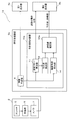
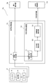
- FIG. 1 is a block diagram showing a configuration of a radar apparatus 1 according to an embodiment of the present invention.
- the radar device 1 includes an antenna unit 2, a signal processing device 3, a first display 4a, and a second display 4b (display unit).
- the antenna unit 2 includes an antenna 5, a receiving unit 6, and an A / D conversion unit 7.
- the antenna 5 is a radar antenna capable of transmitting (radiating) a pulsed radio wave having strong directivity.
- the antenna 5 is configured to receive an echo signal (reflected wave) from a target. That is, the antenna 5 is configured to receive an echo signal that identifies a target.
- the radar apparatus 1 measures the time from when a pulsed radio wave is transmitted to when an echo signal is received. Thereby, the radar apparatus 1 can detect the distance r to the target.
- the direction in which the ship and the target face each other is defined as the distance direction.
- the antenna 5 is configured to be able to rotate 360 ° on a horizontal plane, and rotates around the vertical axis.
- the antenna 5 is configured to repeatedly transmit and receive radio waves while changing the transmission direction of pulsed radio waves (changing the rotation angle of the antenna 5). With the above configuration, the radar apparatus 1 can detect a target on a plane around the ship over 360 °.
- the receiving unit 6 detects and amplifies the echo signal received by the antenna 5.
- the echo signal is a reflected wave at a target or wave front with respect to a transmission signal from the antenna 5 among signals received by the antenna 5.
- the reception unit 6 outputs the amplified echo signal to the A / D conversion unit 7.
- the A / D converter 7 samples an analog echo signal and converts it into digital data (echo data) consisting of a plurality of bits.
- the value of the echo data includes data for specifying the intensity (signal level) of the echo signal received by the antenna 5.
- the A / D converter 7 outputs the echo data to the image generator 8 of the signal processing device 3.
- the signal processing device 3 includes an image generation unit 8 and a pulling wave detection device 10.
- the image generation unit 8 generates image data based on data having a relatively high signal level (for example, other ships) based on the echo data from the A / D conversion unit 7.
- the image generation unit 8 generates PPI (Plan Position Indicator) image data.
- the image data generated by the image generation unit 8 is output to the first display 4a. Thereby, the user can grasp
- the image generation unit 8 generates image data based on the reflected wave from the sea surface based on the echo data from the A / D conversion unit 7.
- the image generation unit 8 generates the image data at a plurality of timings.
- the image data generated in this way is output to the pulling wave detection device 10.
- the trailing wave detection device 10 is configured to estimate the distribution of the wave front velocity vector and the wave line of the trailing wave based on the image data based on the reflected wave from the sea surface.
- the configuration of the pulling wave detection device 10 will be described later in detail.
- the first display 4a displays the image signal generated by the image generation unit 8 (image signal caused by another ship or the like).
- the second display 4b displays the distribution of wave front velocity vectors calculated by the trailing wave detection device 10 and the approximate function of the peak line of the trailing wave.
- the second display 4b is configured to switch and display the wavefront velocity vector distribution and the approximate function by switching a changeover switch (not shown).
- the pulling wave detection device 10 includes a wavefront flow calculation unit 11 (derivation unit), a pulling wave detection unit 12, and a wave peak line estimation unit 13.
- the pulling wave detection device 10 is configured using hardware including a CPU, a RAM, a ROM (not shown), and the like.
- the trailing wave detection device 10 is configured using software including a trailing wave detection program stored in the ROM.
- the pulling wave detection program is a program for causing the pulling wave detection apparatus 10 to execute the pulling wave detection method according to the embodiment of the present invention.
- This program can be installed externally.
- the installed program is distributed while being stored in a recording medium.
- the hardware and software are configured to operate in cooperation.
- the pulling wave detection device 10 can function as the wavefront flow calculation unit 11, the pulling wave detection unit 12, and the wave line estimation unit 13.
- the wavefront flow calculation unit 11 is configured to calculate the velocity vector of the wavefront of the sea surface within a predetermined range (hereinafter referred to as calculation target area A) within a predetermined distance from the own ship centering on the own ship. Specifically, the wavefront flow calculation unit 11 calculates the optical flow of the wavefront using images at a plurality of timings generated by the image generation unit 8.
- the optical flow is a distribution of apparent velocity vectors of a moving object (in this embodiment, a wavefront) in an image. Examples of methods for calculating the optical flow of the wave front include a correlation method and a gradient method. Since these methods are known, a detailed description thereof will be omitted.
- the wavefront velocity vector at each point in the calculation target area A calculated by the wavefront flow calculation unit 11 is output to the second display 4b and the trailing wave detection unit 12.
- FIG. 2 is a diagram illustrating an example of a wavefront velocity vector at each point in the calculation target area A displayed on the second display 4b.
- the magnitude of the wavefront velocity vector at each point is represented by the size of the arrow displayed at each corresponding point, and the direction of the wavefront velocity vector at each point is displayed at each corresponding point. It is represented by the direction of the arrow.
- the trailing wave detection unit 12 is configured to detect a leading wave velocity vector, which is a wave front velocity vector caused by the pulling wave, from the wave front velocity vectors at the respective points calculated by the wave front flow calculating unit 11. Specifically, the pulling wave detection unit 12 targets a pair of wavefront velocity vectors in the wavefront velocity vectors at each point calculated by the wavefront flow calculation unit 11. The pulling wave detection unit 12 then causes the pair of wave front velocity vectors to go in a direction within a predetermined angle range centering on a direction opposite to the direction of the wave front velocity vector on the other side, and the speed is at another point. When the wavefront velocity vector is larger than the reference value based on the velocity of the wavefront velocity vector by a predetermined value or more, the pair of wavefront velocity vectors are set as the wave velocity vectors.
- the wavy line estimation unit 13 estimates the wavy line of the trailing wave based on the representative points of the plurality of trailing wave velocity vectors detected by the trailing wave detection unit 12.
- the ridgeline estimation unit 13 calculates an approximate function of representative points of a plurality of subtraction velocity vectors detected by the subtraction detection unit 12 by, for example, the least square method, and the approximation function is calculated as a subtraction wave. Estimated as a wavy line.
- the representative point of the trailing wave velocity vector is the starting point of the trailing wave velocity vector.
- the trailing point may be an end point, and moreover, between the starting point and the end point. It may be an intermediate point.
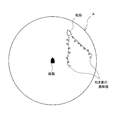
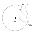
- FIG. 3 is a diagram showing a display example of the wave line of the trailing wave estimated by the wave line estimation unit 13 displayed on the second display 4b.
- the undulating ridgeline is approximated by the undulating line estimator 13 in the second display 4 b together with the echo image of the other ship and the X mark indicating the starting point of the undulating velocity vector. Displayed by displaying the ridgeline of the pulling wave represented by the function.
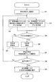
- FIG. 4 is a flowchart for explaining the operation of the pulling wave detection apparatus 10.
- FIG. 5 is a diagram for explaining the operation of the trailing wave detection device 10 and shows only a part of the wavefront velocity vectors. With reference to FIG.4 and FIG.5, the process at the time of detecting a trailing wave is demonstrated.
- step S1 the pulling wave detection apparatus 10 sets an arbitrary azimuth direction (in the case of FIG. 5, ⁇ 1 ) around the ship.
- step S2 undertow detection apparatus 10, as a target vector multiple wave front velocity vector aligned along the azimuth direction theta 1, the distance r from the ship of each target vector, the absolute value of each target vector A graph (see FIG. 6) showing the relationship with (speed) is created.
- step S3 the pulling wave detection apparatus 10 creates a graph (see FIG. 7) showing the relationship between the distance r of each target vector from the ship and the direction of each target vector.
- step S4 the trailing wave detection unit 12 determines whether or not a plurality of target vectors have a predetermined feature based on the graphs created in steps S2 and S3. Specifically, in the present embodiment, for example, as an example, the pulling wave detection unit 12 determines that the absolute value of the vector is larger than the reference value based on the speed of the wavefront velocity vector at other points from the graph illustrated in FIG. When there are two waveforms having two vectors (V 1 and V 2 in FIG. 6) as local maximum values, these two vectors V 1 and V 2 are extracted as determination target vectors. When the two vectors as described above do not exist, the trailing wave detection unit 12 determines that there are no trailing waves for the plurality of target vectors because the plurality of target vectors do not have a predetermined feature (step S6). Proceed to step S7.
- the reference value is, for example, an average value V AVE of speeds of wave front vectors at a point between the two waveforms as shown in FIG.
- the reference value is not limited to this, and may be the speed of the wave front vector at any point between the two waveforms.
- the subtraction wave detection unit 12 determines that the angle difference ⁇ D between the pair of determination target vectors V 1 and V 2 is within a predetermined angle range. It is determined whether or not there is. If the angle difference ⁇ D is within the predetermined angle range, the pulling wave detection unit 12 detects that the pair of determination target vectors V 1 and V 2 are pulling waves (step S5), and proceeds to step S7. On the other hand, if the angle difference ⁇ D exceeds the predetermined angle range (No in step S4), pull wave detection unit 12 determines that not the undertow a pair to be determined vectors V 1 and V 2 (step S5) The process proceeds to step S7.
- the predetermined angular range in the step S4, a pair of the determination target vectors V 1 and V 2 are, as the angular range toward the direction of the predetermined angle range around the direction opposite to the direction of the wave front velocity vector of the mating each other Is set.
- the predetermined angle range is set as an angle range of 170 degrees to 190 degrees.
- step S7 the trailing wave detection device 10 sets a new azimuth direction by shifting the azimuth direction by a predetermined angle. Specifically, in the case of FIG. 5, the azimuth direction is shifted from ⁇ 1 to ⁇ 2 .
- step S8 when the detection of the trailing wave is completed for all the azimuth directions (Yes in step S8), the process proceeds to step S9.
- the process returns to Step S2 and Step S3. Then, the pulling wave detection apparatus 10 performs steps S2 and S3 and subsequent steps for the newly set azimuth direction as in the case described above.
- step S8 When the flow from step S1 to step S8 described above is repeated and the detection of the trailing wave for each point in the calculation target area A is completed (Yes in step S8), the undulating line estimation unit 13 performs the undulating ridgeline. Is estimated.
- FIG. 8 is a graph for explaining a method for estimating a wave ridge line derived from a plurality of wave waves detected as described above.
- the undulating line estimation unit 13 calculates an approximate function of representative points of a plurality of subtraction velocity vectors by, for example, the least square method, and uses the approximate function as a subduction undulation line.
- the approximate function include a linear function, a quadratic function, and the like. However, the approximate function is not limited thereto, and other functions may be used.
- the wave line of the estimated wave estimated as described above is displayed on the second display 4b together with the representative point of the wave velocity vector (in this embodiment, the starting point of the wave velocity vector). Is done. Thereby, the user can visually recognize the ridgeline of the pulling wave with respect to the ship.
- the display state on the second display 4b is not limited to that shown in FIG. 3, but only the undulation line of the trailing wave is displayed without displaying the representative point of the trailing wave velocity vector, for example, as shown in FIG. May be.
- the pair of wavefront velocity vectors V 1 and V 2 in the calculation target area A are drawn according to the pulling wave. Detect as wave velocity vector.
- the pair of wave front velocity vectors V 1 and V 2 are directed in a direction within a predetermined angle range centering on a direction opposite to the direction of the wave front velocity vector on the other side, and
- the speed is larger than a reference value VAVE based on the speed of the wavefront velocity vector at another point by a predetermined value or more, it is detected as a drawing wave velocity vector caused by the drawing wave.
- a pair of undulation lines of a pulling wave of a ship navigating on the water is formed behind the navigating ship.
- the direction of the velocity vector of these pair of undulations of the pulling waves is generally opposite, and the magnitude thereof is larger than the magnitude of the wavefront velocity vector at other points. Therefore, by detecting the pair of wavefront velocity vectors V 1 and V 2 as the wave velocity vector when the above conditions are satisfied, the wave velocity vector can be detected under an appropriate condition.
- the pulling wave detection device 10 can appropriately detect the pulling wave generated by the navigation of the ship.
- the trailing wave detection device 10 estimates the trailing wave peak line based on the representative points of the plurality of trailing wave velocity vectors, the trailing wave peak line can be estimated appropriately.
- the trailing wave detection apparatus 10 calculates an approximate function of representative points of a plurality of trailing wave velocity vectors, and estimates the trailing wave peak line based on the approximate function. Can be estimated appropriately.
- the wave line of the pulling wave estimated by the pulling wave detection device 10 is displayed on the second display 4b. Therefore, the user can visually recognize the undulation line of the pulling wave appropriately.
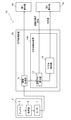
- FIG. 10 is a block diagram showing a configuration of a radar apparatus 1a according to a modification.
- the pulling wave detection device 10 a of the radar apparatus 1 a according to this modification further includes an image feature detection unit 14, unlike the case of the above embodiment.
- the ridge line estimation unit 13a includes the representative point of the trailing wave velocity vector detected by the trailing wave detection unit 12, and the image feature detected by the image feature detection unit 14. Based on the above, the approximate function of the wave line of the pulling wave is calculated.
- a pair of undulating ridge lines are formed behind the navigating ship.
- the pair of pulling wave peaks are usually formed in a pair of straight lines that are separated from each other as the distance from the ship increases, as shown in FIG.
- the image feature detection unit 14 of the pulling wave detection apparatus 10a has two line segments that do not intersect with each other and are not parallel to each other, and an angle between them is arbitrary.
- An image P having a feature of an angle (for example, 45 degrees) is stored.
- the angle between two line segments that are images stored in the image feature detection unit 14 is an angle (30 degrees) shown in FIG. 11B and an angle (90 degrees) shown in FIG. 11C. Other angles may be used.
- a plurality of images may be stored in the image feature detection unit 14.
- the image feature detection unit 14 detects an image feature having a feature like the image P from the wavefront echo image generated by the image generation unit 8.
- the ridge line estimation unit 13a detects the representative points of the plurality of trailing wave velocity vectors detected by the trailing wave detection unit 12 and the feature detected by the image feature detection unit 14. Based on both the image and the approximate function of the undulation line of the pulling wave. As a result, the undulation line of the pulling wave can be approximated by an approximation function with higher accuracy.
- FIG. 12 is a block diagram showing a configuration of a radar apparatus 1b according to a modification. As shown in FIG. 12, the radar apparatus 1b according to this modification has a configuration in which the wave line estimation unit 13 is omitted, unlike the case of the above embodiment.
- the pulling wave detection unit 12 of this modification detects a plurality of pulling wave velocity vectors in the calculation target area A in the same manner as the pulling wave detection unit 12 of the above embodiment.
- FIG. 13 is a diagram showing a display example of representative points of a plurality of wave velocity vectors detected by the wave detector 12 displayed on the second display 4b.
- the position of the representative point of the wave velocity vector is displayed with an X mark.
- FIG. 13 only representative points of the pulling wave velocity vector are displayed.
- the present invention is not limited to this, and a pulling wave velocity vector represented by an arrow may be displayed.
- the trailing wave velocity detection apparatus 10b detects the trailing wave velocity vector in the same manner as in the above embodiment. Therefore, as in the case of the above-described embodiment, a pulling wave can be detected appropriately.
- the target vector set for detecting the pulling wave velocity vector is set in each of the azimuth directions around the ship. It is set sequentially along the radial direction. That is, in the pulling wave detection device 10 according to the above embodiment, the pulling wave velocity vector is detected based on the r- ⁇ coordinate.
- the present invention is not limited to this, and as shown in FIG. 14, the wave velocity vector may be detected based on the xy coordinates. In this case, for example, as an example, a virtual straight line extending in the x direction in the calculation target area A is set, a target vector is set along the virtual straight line, and a trailing wave velocity vector is detected.
- the virtual line is shifted in the y direction
- the target vector is set along the shifted virtual line in the same manner as described above, and the wave velocity vector is detected.
- the wave velocity vector can be detected in the calculation target area A.
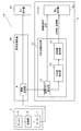
- FIG. 15 is a block diagram showing a configuration of a radar apparatus 1c according to a modification.
- the wavefront flow calculation unit 11 is calculated based on the optical flow.
- the wavefront flow calculation unit 11b according to this modification includes, for example, a reflected wave of the pulse wave transmitted from the antenna 5 at the first timing, and a reflected wave of the pulse wave transmitted from the antenna 5 at the second timing,
- the wavefront velocity vector at each point in the calculation target area A is calculated on the basis of the frequency difference.
- FIG. 16 is a block diagram showing the configuration of the personal computer 9 having the radar device 1d and the wave detection device 10 according to the modification.
- the trailing wave detection device 10 may be provided in a personal computer 9 separate from the radar device 1d. In this case, it is only necessary to display the wave line of the wave that is the calculation result of the wave detection device 10 on the second display 4 b configured by the display of the personal computer 9.
- the wave line of the wave detected by the wave detection device 10 is displayed on the display unit to allow the user to recognize it.
- the present invention is not limited to this.
- the hull control unit 15, which is a control unit of the ship may be controlled based on information about the wave line of the wave detected by the wave detection device 10.
- the present invention can be widely applied as a pulling wave detection apparatus, a radar apparatus including the pulling wave detection apparatus, a pulling wave detection method for detecting a pulling wave, and a pulling wave detection program.
Landscapes
- Engineering & Computer Science (AREA)
- Radar, Positioning & Navigation (AREA)
- Remote Sensing (AREA)
- Ocean & Marine Engineering (AREA)
- Physics & Mathematics (AREA)
- Chemical & Material Sciences (AREA)
- Mechanical Engineering (AREA)
- Combustion & Propulsion (AREA)
- Computer Networks & Wireless Communication (AREA)
- General Physics & Mathematics (AREA)
- Electromagnetism (AREA)
- Life Sciences & Earth Sciences (AREA)
- Atmospheric Sciences (AREA)
- Environmental & Geological Engineering (AREA)
- Radar Systems Or Details Thereof (AREA)
Abstract
【課題】船舶の航行によって発生する引き波を適切に検出する。 【解決手段】所定範囲の各地点における水面の波頭の速度ベクトルである波頭速度ベクトルを導出する導出部11と、導出部11で導出された各地点における波頭速度ベクトルのうちの一対の波頭速度ベクトルであって、互いに相手側の波頭速度ベクトルの向きの反対方向を中心とした所定角度範囲内の方向へ向かい、且つその速さが他の地点における波頭速度ベクトルの速さに基づく基準値よりも所定値以上大きい一対の波頭速度ベクトルを、水上を航行する船舶の後方に発生する一対の引き波に起因する引き波速度ベクトルとし、複数の引き波速度ベクトルを検出する引き波検出部12と、を備えている引き波検出装置10bを構成する。
Description
本発明は、引き波(船舶の航行によって当該船舶の後方に発生する波)を検出する引き波検出装置、引き波検出装置を備えたレーダ装置、引き波を検出するための引き波検出方法、及び引き波検出プログラムに関する。
従来より、海面の波頭の動きを推定するための手法として、例えば特許文献1に示すような手法が知られている。具体的には、特許文献1では、海洋レーダによって得られた受信信号に基づいて、波頭の動きを検出している。
ところで、海面の波頭の動きのうち特徴的なものとして、船舶の航行によって当該船舶の後方に発生する波である引き波が知られている。この引き波は、船舶の大きさ及び速度に依存して、その波の高さ及び速度が変化する。
よって、例えば、自船を航行する際、他船(特に大型船)が高速で航行することによって発生した大きな引き波によって自船が大きく揺らいでしまい、場合によっては転覆するおそれがある。
本発明は、上記課題を解決するためのものであり、その目的は、船舶の航行によって発生する引き波を適切に検出することである。
(1)上記課題を解決するために、この発明のある局面に係る引き波検出装置は、所定範囲の各地点における水面の波頭の速度ベクトルである波頭速度ベクトルを導出する導出部と、前記導出部で導出された各地点における前記波頭速度ベクトルのうちの一対の波頭速度ベクトルであって、互いに相手側の波頭速度ベクトルの向きの反対方向を中心とした所定角度範囲内の方向へ向かい、且つその速さが他の地点における前記波頭速度ベクトルの速さに基づく基準値よりも所定値以上大きい前記一対の波頭速度ベクトルを、水上を航行する船舶の後方に発生する一対の引き波に起因する引き波速度ベクトルとし、複数の該引き波速度ベクトルを検出する引き波検出部と、を備えている。
(2)好ましくは、前記引き波検出装置は、複数の前記引き波速度ベクトルの代表点に基づいて、前記一対の引き波の波峰線を推定する波峰線推定部を更に備えている。
(3)更に好ましくは、前記波峰線推定部は、複数の前記引き波速度ベクトルの代表点の近似関数を算出し、該近似関数に基づいて前記一対の引き波の波峰線を推定する。
(4)好ましくは、前記引き波検出装置は、前記所定範囲における水面の波頭のエコー画像から、所定の画像特徴を検出する画像特徴検出部を更に備え、前記波峰線推定部は、前記画像特徴検出部で検出された前記所定の画像特徴に基づいて、前記一対の引き波の波峰線を推定する。
(5)上記課題を解決するために、この発明のある局面に係るレーダ装置は、電波を送受信するアンテナと、前記アンテナが受信した受信信号に基づいて、所定範囲の各地点における水面の波頭の速度ベクトルである波頭速度ベクトルを導出する導出部、を有する、上述したいずれかの引き波検出装置と、前記引き波検出装置で検出された複数の引き波速度ベクトル、前記複数の引き波速度ベクトルの代表点、及び、前記引き波検出装置の波峰線推定部で推定された前記一対の引き波の波峰線、のうちの少なくともいずれかを表示する表示部と、を備えている。
(6)上記課題を解決するために、この発明のある局面に係る引き波検出方法は、所定範囲の各地点における水面の波頭の速度ベクトルである波頭速度ベクトルを導出するステップと、前記ステップで導出された各地点における前記波頭速度ベクトルのうちの一対の波頭速度ベクトルであって、互いに相手側の波頭速度ベクトルの向きの反対方向を中心とした所定角度範囲内の方向へ向かい、且つその速さが他の地点における前記波頭速度ベクトルの速さに基づく基準値よりも所定値以上大きい前記一対の波頭速度ベクトルを、水上を航行する船舶の後方に発生する一対の引き波に起因する引き波速度ベクトルとし、複数の該引き波速度ベクトルを検出するステップと、を含む。
(7)上記課題を解決するために、この発明のある局面に係る引き波検出プログラムは、所定範囲の各地点における水面の波頭の速度ベクトルである波頭速度ベクトルを導出するステップと、前記ステップで導出された各地点における前記波頭速度ベクトルのうちの一対の波頭速度ベクトルであって、互いに相手側の波頭速度ベクトルの向きの反対方向を中心とした所定角度範囲内の方向へ向かい、且つその速さが他の地点における前記波頭速度ベクトルの速さに基づく基準値よりも所定値以上大きい前記一対の波頭速度ベクトルを、水上を航行する船舶の後方に発生する一対の引き波に起因する引き波速度ベクトルとし、複数の該引き波速度ベクトルを検出するステップと、を含む。
本発明によれば、船舶の航行によって発生する引き波を検出できる。
本発明の実施形態に係る引き波検出装置10、及び引き波検出装置10を備えるレーダ装置1について、図を参照して説明する。本発明の実施形態に係るレーダ装置1は、例えば船舶(自船)に装備され、海上の物標(例えば他船)を探知するために用いられる。そして、本実施形態に係るレーダ装置1は、引き波検出装置10によって、他船の引き波(他船の航行によって当該他船の後方に発生する波)を検出できるように構成されている。
[全体構成]
図1は、本発明の実施形態に係るレーダ装置1の構成を示すブロック図である。レーダ装置1は、図1に示すように、アンテナユニット2と、信号処理装置3と、第1表示器4aと、第2表示器4b(表示部)と、を備えている。
図1は、本発明の実施形態に係るレーダ装置1の構成を示すブロック図である。レーダ装置1は、図1に示すように、アンテナユニット2と、信号処理装置3と、第1表示器4aと、第2表示器4b(表示部)と、を備えている。
アンテナユニット2は、アンテナ5と、受信部6と、A/D変換部7と、を含んでいる。
アンテナ5は、指向性の強いパルス状電波を送信(放射)可能なレーダアンテナである。また、アンテナ5は、物標からのエコー信号(反射波)を受信するように構成されている。即ち、アンテナ5は、物標を特定するエコー信号を受信するように構成されている。レーダ装置1は、パルス状電波を送信してからエコー信号を受信するまでの時間を測定する。これにより、レーダ装置1は、物標までの距離rを検出することができる。自船と物標とが向かい合う方向は、距離方向として定義される。
アンテナ5は、水平面上で360°回転可能に構成されており、鉛直軸線回りを回転する。アンテナ5は、パルス状電波の送信方向を変えながら(アンテナ5の回転角度を変えながら)、電波の送受信を繰り返し行うように構成されている。以上の構成で、レーダ装置1は、自船周囲の平面上の物標を、360°にわたり探知することができる。
受信部6は、アンテナ5で受信したエコー信号を検波して増幅する。エコー信号は、アンテナ5で受信された信号のうち、アンテナ5からの送信信号に対する、物標又は波頭での反射波である。受信部6は、増幅したエコー信号を、A/D変換部7へ出力する。A/D変換部7は、アナログ形式のエコー信号をサンプリングし、複数ビットからなるデジタルデータ(エコーデータ)に変換する。ここで、上記エコーデータの値は、アンテナ5が受信したエコー信号の強度(信号レベル)を特定するデータを含んでいる。A/D変換部7は、エコーデータを、信号処理装置3の画像生成部8へ出力する。
信号処理装置3は、画像生成部8と、引き波検出装置10と、を含んでいる。
画像生成部8は、A/D変換部7からのエコーデータに基づき、比較的信号レベルが大きいデータ(例えば他船等)に基づく画像データを生成する。本実施形態では、画像生成部8は、PPI(Plan Position Indicator)画像データを生成する。画像生成部8で生成された画像データは、第1表示器4aに出力される。これにより、ユーザは、自船位置を基準とした他船位置を把握することができる。
また、画像生成部8は、A/D変換部7からのエコーデータに基づき、海面からの反射波に基づく画像データを生成する。画像生成部8は、複数のタイミングにおける前記画像データを生成する。このように生成された画像データは、引き波検出装置10に出力される。
引き波検出装置10は、海面からの反射波に基づく上記画像データに基づき、波頭速度ベクトルの分布と、引き波の波峰線と、を推定するように構成されている。引き波検出装置10の構成については、詳しくは後述する。
第1表示器4aは、画像生成部8で生成された画像信号(他船等に起因する画像信号)を表示する。また、第2表示器4bは、引き波検出装置10で算出された波頭速度ベクトルの分布、及び引き波の波峰線の近似関数を表示する。例えば、第2表示器4bは、切替スイッチ(図示省略)を切り替えることにより、波頭速度ベクトルの分布と上記近似関数とを切り替えて表示されるように構成されている。
[引き波検出装置の構成]
引き波検出装置10は、図1に示すように、波頭フロー算出部11(導出部)と、引き波検出部12と、波峰線推定部13と、を備えている。引き波検出装置10は、CPU、RAM及びROM(図示せず)等を含むハードウェアを用いて構成されている。また、引き波検出装置10は、ROMに記憶された引き波検出プログラムを含むソフトウェアを用いて構成されている。
引き波検出装置10は、図1に示すように、波頭フロー算出部11(導出部)と、引き波検出部12と、波峰線推定部13と、を備えている。引き波検出装置10は、CPU、RAM及びROM(図示せず)等を含むハードウェアを用いて構成されている。また、引き波検出装置10は、ROMに記憶された引き波検出プログラムを含むソフトウェアを用いて構成されている。
上記引き波検出プログラムは、本発明の一実施形態における引き波検出方法を、引き波検出装置10に実行させるためのプログラムである。このプログラムは、外部からインストールできる。このインストールされるプログラムは、例えば、記録媒体に格納された状態で流通する。上記ハードウェアとソフトウェアとは、協働して動作するように構成されている。これにより、引き波検出装置10を、波頭フロー算出部11、引き波検出部12、及び波峰線推定部13として機能させることができる。
波頭フロー算出部11は、自船を中心とし自船から所定距離以内の所定範囲(以降、算出対象エリアAと称する)内における海面の波頭の速度ベクトルを算出するように構成されている。具体的には、波頭フロー算出部11は、画像生成部8で生成された複数のタイミングでの画像を用いて、波頭のオプティカルフローを算出する。オプティカルフローとは、画像中における運動物体(本実施形態では、波頭)の見かけの速度ベクトルの分布である。波頭のオプティカルフローを算出する手法としては、例えば、相関法、勾配法等が挙げられる。これらの手法については、公知であるため、その詳細な説明は省略する。
波頭フロー算出部11で算出された、算出対象エリアA内における各地点の波頭の速度ベクトルは、第2表示器4b、及び引き波検出部12に出力される。
図2は、第2表示器4bで表示される、算出対象エリアA内における各地点の波頭速度ベクトルの一例を示す図である。図2に示す例では、各地点の波頭速度ベクトルの大きさは、対応する各地点に表示された矢印の大きさで表され、各地点の波頭速度ベクトルの向きは、対応する各地点に表示された矢印の向きで表される。
引き波検出部12は、波頭フロー算出部11で算出された各地点における波頭速度ベクトルの中から、引き波に起因する波頭速度ベクトルである引き波速度ベクトルを検出するように構成されている。具体的には、引き波検出部12は、波頭フロー算出部11で算出された各地点における波頭速度ベクトルにおいて一対の波頭速度ベクトルを対象とする。そして、引き波検出部12は、当該一対の波頭速度ベクトルが、互いに相手側の波頭速度ベクトルの向きの反対方向を中心とした所定角度範囲内の方向へ向かい、且つその速さが他の地点における前記波頭速度ベクトルの速さに基づく基準値よりも所定値以上大きい場合、当該一対の波頭速度ベクトルを引き波速度ベクトルとする。
波峰線推定部13は、引き波検出部12で検出された複数の引き波速度ベクトルの代表点に基づいて、引き波の波峰線を推定する。本実施形態では、波峰線推定部13は、引き波検出部12で検出された複数の引き波速度ベクトルの代表点の近似関数を、例えば最小二乗法によって算出し、当該近似関数を、引き波の波峰線として推定する。なお、本実施形態では、引き波速度ベクトルの代表点を、当該引き波速度ベクトルの始点としているが、これに限らす、例えば終点であってもよく、更には、始点と終点との間の中間点であってもよい。
図3は、第2表示器4bで表示される、波峰線推定部13で推定された引き波の波峰線の表示例を示す図である。図3に示すように、引き波の波峰線は、第2表示器4bにおいて、他船のエコー画像、及び引き波速度ベクトルの始点を表すX印とともに、波峰線推定部13で推定された近似関数で表される引き波の波峰線を表示することにより表示される。なお、上述した引き波速度ベクトルの始点を表すX印の表示については、その代わりに、引き波速度ベクトルの始点と終点とを結ぶ直線で表示してもよい。
[引き波検出装置の動作]
図4は、引き波検出装置10の動作を説明するためのフローチャートである。また、図5は、引き波検出装置10の動作を説明するための図であって、一部の波頭速度ベクトルのみを示す図である。図4及び図5を参照して、引き波を検出する際の工程を説明する。
図4は、引き波検出装置10の動作を説明するためのフローチャートである。また、図5は、引き波検出装置10の動作を説明するための図であって、一部の波頭速度ベクトルのみを示す図である。図4及び図5を参照して、引き波を検出する際の工程を説明する。
まず、ステップS1で、引き波検出装置10は、自船を中心とした任意の方位方向(図5の場合、θ1)を設定する。
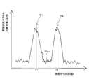
次に、ステップS2で、引き波検出装置10は、方位方向θ1に沿って並ぶ複数の波頭速度ベクトルを対象ベクトルとして、各対象ベクトルの自船からの距離rと、各対象ベクトルの絶対値(速さ)との関係を示すグラフ(図6参照)を作成する。
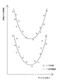
また、ステップS3で、引き波検出装置10は、各対象ベクトルの自船からの距離rと、各対象ベクトルの向きとの関係を示すグラフ(図7参照)と、を作成する。
次に、ステップS4で、引き波検出部12は、ステップS2及びステップS3で作成された各グラフに基づいて、複数の対象ベクトルに所定の特徴があるか否かを判定する。具体的に、本実施形態では、例えば一例として、引き波検出部12は、図6に示すグラフから、ベクトルの絶対値が、他の地点における波頭速度ベクトルの速さに基づく基準値よりも大きい2つのベクトル(図6におけるV1とV2)を極大値として有する2つの波形がある場合、これらの2つのベクトルV1及びV2を、判定対象ベクトルとして抽出する。上述のような2つのベクトルが存在しない場合、引き波検出部12は、複数の対象ベクトルに所定の特徴がないため、当該複数の対象ベクトルについては引き波がないと判定し(ステップS6)、ステップS7に進む。
なお、上記基準値とは、例えば一例として、図6に示すように、上記2つの波形の間の地点における波頭ベクトルの速さの平均値VAVE、である。しかし、上記基準値は、これに限らず、上記2つの波形の間における任意に地点の波頭ベクトルの速さ、であってもよい。
上述のように2つのベクトルV1及びV2が判定対象ベクトルとして抽出された場合、引き波検出部12は、当該一対の判定対象ベクトルV1及びV2の角度差ΔDが所定角度範囲内であるか否かを判定する。上記角度差ΔDが所定角度範囲内であれば、引き波検出部12は、一対の判定対象ベクトルV1及びV2を引き波であると検出し(ステップS5)、ステップS7に進む。一方、上記角度差ΔDが所定角度範囲を超えていれば(ステップS4のNo)、引き波検出部12は、一対の判定対象ベクトルV1及びV2を引き波でないと判定し(ステップS5)、ステップS7に進む。
なお、上記ステップS4における所定角度範囲は、一対の判定対象ベクトルV1及びV2が、互いに相手側の波頭速度ベクトルの向きの反対方向を中心とした所定角度範囲内の方向に向かう角度範囲として設定される。例えば一例として、上記所定角度範囲は、170度から190度の角度範囲として設定される。
次に、ステップS7で、引き波検出装置10は、方位方向を所定角度ずらして新たな方位方向を設定する。具体的には、図5の場合、方位方向をθ1からθ2にずらす。
次に、ステップS8で、全ての方位方向について引き波の検出が終了している場合(ステップS8のYes)、ステップS9に進む。一方、ステップS8で、全ての方位方向について引き波の検出が終了していない場合(ステップS8のNo)、ステップS2及びステップS3に戻る。そして、引き波検出装置10は、新たに設定された方位方向について、上述の場合と同様、ステップS2及びステップS3以降のステップを行う。
上述したステップS1からステップS8までのフローが繰り返され、算出対象エリアA内の各地点についての引き波の検出が終了すると(ステップS8のYes)、波峰線推定部13は、引き波の波峰線を推定する。
図8は、上述のようにして検出された複数の引き波から導出される引き波の波峰線の推定手法について説明するためのグラフである。図8に示すように、ステップS9では、波峰線推定部13は、複数の引き波速度ベクトルの代表点の近似関数を、例えば最小二乗法によって算出し、当該近似関数を引き波の波峰線として推定する。なお、上記近似関数としては、例えば、一次関数、二次関数等が挙げられるが、これらに限らず、その他の関数であってもよい。
上述のように推定された引き波の波峰線は、図3に示すように、引き波速度ベクトルの代表点(本実施形態では、引き波速度ベクトルの始点)とともに、第2表示器4bに表示される。これにより、ユーザは、自船に対する引き波の波峰線を視覚的に認識できる。
なお、第2表示器4bへの表示状態は、図3に示すものに限らず、例えば図9に示すように、引き波速度ベクトルの代表点を表示せずに引き波の波峰線のみを表示してもよい。
[効果]
以上のように、本実施形態に係る引き波検出装置10では、以下の条件を満たした場合に、算出対象エリアA内における一対の波頭速度ベクトルV1,V2を、引き波に起因する引き波速度ベクトルとして検出する。具体的には、引き波検出装置10では、一対の波頭速度ベクトルV1,V2が、互いに相手側の波頭速度ベクトルの向きの反対方向を中心とした所定角度範囲内の方向へ向かい、且つその速さが他の地点における前記波頭速度ベクトルの速さに基づく基準値VAVEよりも所定値以上大きい場合、引き波に起因する引き波速度ベクトルとして検出する。
以上のように、本実施形態に係る引き波検出装置10では、以下の条件を満たした場合に、算出対象エリアA内における一対の波頭速度ベクトルV1,V2を、引き波に起因する引き波速度ベクトルとして検出する。具体的には、引き波検出装置10では、一対の波頭速度ベクトルV1,V2が、互いに相手側の波頭速度ベクトルの向きの反対方向を中心とした所定角度範囲内の方向へ向かい、且つその速さが他の地点における前記波頭速度ベクトルの速さに基づく基準値VAVEよりも所定値以上大きい場合、引き波に起因する引き波速度ベクトルとして検出する。
水上を航行する船舶の引き波の波峰線は、一般的に、当該航行する船舶の後方に一対、形成される。そして、これらの一対の引き波の波峰線は、その速度ベクトルの向きが概ね反対方向を向き、且つ、その大きさが、他の地点の波頭速度ベクトルの大きさよりも大きくなっている。よって、一対の波頭速度ベクトルV1,V2を、上述のような条件を満たした場合に引き波速度ベクトルとして検出することで、適切な条件で、引き波速度ベクトルを検出できる。
従って、引き波検出装置10では、船舶の航行によって発生する引き波を適切に検出できる。
また、引き波検出装置10では、複数の引き波速度ベクトルの代表点に基づいて、引き波の波峰線を推定しているため、引き波の波峰線を適切に推定できる。
また、引き波検出装置10では、複数の引き波速度ベクトルの代表点の近似関数を算出し、該近似関数に基づいて引き波の波峰線を推定しているため、引き波の波峰線をより適切に推定できる。
また、レーダ装置1では、引き波検出装置10によって推定された引き波の波峰線が、第2表示器4bに表示される。従って、ユーザは、引き波の波峰線を、視覚的に適切に認識できる。
以上、本発明の実施形態について説明したが、本発明はこれらに限定されるものではなく、本発明の趣旨を逸脱しない限りにおいて種々の変更が可能である。
[変形例]
(1)図10は、変形例に係るレーダ装置1aの構成を示すブロック図である。図10に示すように、本変形例に係るレーダ装置1aの引き波検出装置10aは、上記実施形態の場合と異なり、画像特徴検出部14を更に備えている。そして、本変形例の引き波検出装置10aは、波峰線推定部13aは、引き波検出部12で検出された引き波速度ベクトルの代表点と、画像特徴検出部14で検出された画像特徴とに基づいて、引き波の波峰線の近似関数を算出するように構成されている。
(1)図10は、変形例に係るレーダ装置1aの構成を示すブロック図である。図10に示すように、本変形例に係るレーダ装置1aの引き波検出装置10aは、上記実施形態の場合と異なり、画像特徴検出部14を更に備えている。そして、本変形例の引き波検出装置10aは、波峰線推定部13aは、引き波検出部12で検出された引き波速度ベクトルの代表点と、画像特徴検出部14で検出された画像特徴とに基づいて、引き波の波峰線の近似関数を算出するように構成されている。
一般的に、引き波の波峰線は、航行する船舶の後方に一対、形成される。そして、この一対の引き波の波峰線は、通常、図3等に示すように、船舶から離れるにつれて互いに離反する一対の直線状に形成される。
本変形例に係る引き波検出装置10aの画像特徴検出部14には、例えば図11(A)に示すように、互いに交差せず且つ平行でない2本の線分を有しその間の角度が任意の角度(例えば、45度)である特徴を有する画像P、が記憶されている。なお、画像特徴検出部14に記憶される画像である2本の線分の間の角度は、図11(B)に示す角度(30度)、図11(C)に示す角度(90度)のように、その他の角度であってもよい。更には、画像特徴検出部14に記憶される画像は、複数であってもよい。
画像特徴検出部14は、画像生成部8で生成された波頭のエコー画像から、画像Pのような特徴を有する画像特徴を検出する。そして、このような画像特徴が検出された場合、波峰線推定部13aは、引き波検出部12によって検出された複数の引き波速度ベクトルの代表点と、画像特徴検出部14によって検出された特徴画像と、の両方に基づいて、引き波の波峰線の近似関数を算出する。これにより、引き波の波峰線を、更に精度が高い近似関数で近似することができる。
(2)図12は、変形例に係るレーダ装置1bの構成を示すブロック図である。図12に示すように、本変形例に係るレーダ装置1bは、上記実施形態の場合と異なり、波峰線推定部13が省略された構成となっている。
本変形例の引き波検出部12は、上記実施形態の引き波検出部12と同様にして、算出対象エリアAにおいて複数の引き波速度ベクトルを検出する。
図13は、第2表示器4bで表示される、引き波検出部12で検出された複数の引き波速度ベクトルの代表点の表示例を示す図である。本変形例の第2表示器4bには、引き波速度ベクトルの代表点の位置が、X印が表示される。なお、図13では、引き波速度ベクトルの代表点のみを表示しているが、これに限らず、矢印で表された引き波速度ベクトルを表示してもよい。
以上のように、本変形例に係る引き波検出装置10bでは、上記実施形態の場合と同様にして、引き波速度ベクトルを検出している。従って、上記実施形態の場合と同様、引き波を適切に検出できる。
また、レーダ装置1bでは、引き波検出装置10bによって推定された複数の引き波速度ベクトルの代表点が表示される。従って、ユーザは、引き波の位置を、視覚的に適切に認識できる。
(3)上記実施形態に係る引き波検出装置10では、図5に示すように、引き波速度ベクトルを検出するために設定される対象ベクトルを、自船を中心とした方位方向のそれぞれにおいて、径方向に沿って順次、設定している。すなわち、上記実施形態に係る引き波検出装置10では、r-θ座標に基づいて引き波速度ベクトルを検出している。しかし、これに限らず、図14に示すように、x-y座標に基づいて引き波速度ベクトルを検出してもよい。この場合、例えば一例として、算出対象エリアA内においてx方向に延びる仮想直線を設定し、当該仮想直線に沿って対象ベクトルを設定し、引き波速度ベクトルを検出する。そして、上記仮想直線をy方向にずらしていき、ずらされた仮想直線に沿って上述の場合と同様に対象ベクトルを設定し、引き波速度ベクトルを検出する。これにより、上記実施形態の場合と同様、算出対象エリアA内において引き波速度ベクトルを検出できる。
(4)図15は、変形例に係るレーダ装置1cの構成を示すブロック図である。上記実施形態では、波頭フロー算出部11を、オプティカルフローに基づいて算出したが、これに限らず、ドップラー計測によって算出してもよい。本変形例に係る波頭フロー算出部11bは、例えば、第1のタイミングでアンテナ5から送信されたパルス波の反射波と、第2のタイミングでアンテナ5から送信されたパルス波の反射波と、の周波数差に基づいて、算出対象エリアAの各地点における波頭速度ベクトルを算出するように構成されている。
(5)図16は、変形例に係るレーダ装置1d、及び引き波検出装置10を有するパソコン9の構成を示すブロック図である。図16に示すように、引き波検出装置10を、レーダ装置1dとは別体のパソコン9に設けてもよい。この場合、引き波検出装置10での算出結果である引き波の波峰線を、パソコン9のディスプレイで構成された第2表示器4bに表示すればよい。
(6)上記実施形態では、引き波検出装置10で検出された引き波の波峰線を、表示部に表示してユーザに認識させていたが、これに限らない。例えば、図17に示すように、引き波検出装置10で検出された引き波の波峰線に関する情報に基づいて、船舶の制御部である船体制御部15を制御してもよい。具体的に、船体制御部15は、例えば一例として、波峰線推定部13で算出された引き波の波峰線の位置及び速度等の情報に基づき、自船が引き波によって転覆しないよう、自船の速度や針路を制御する。これにより、自船が引き波によって転覆することを、未然に防ぐことができる。
本発明は、引き波検出装置、この引き波検出装置を備えたレーダ装置、引き波を検出するための引き波検出方法、及び引き波検出プログラムとして広く適用することができる。
1,1a,1b,1c,1d,1e レーダ装置
10,10a,10b,10c 引き波検出装置
11,11a 波頭フロー算出部(導出部)
12 引き波検出部
13,13a 波峰線推定部
10,10a,10b,10c 引き波検出装置
11,11a 波頭フロー算出部(導出部)
12 引き波検出部
13,13a 波峰線推定部
Claims (7)
- 所定範囲の各地点における水面の波頭の速度ベクトルである波頭速度ベクトルを導出する導出部と、
前記導出部で導出された各地点における前記波頭速度ベクトルのうちの一対の波頭速度ベクトルであって、互いに相手側の波頭速度ベクトルの向きの反対方向を中心とした所定角度範囲内の方向へ向かい、且つその速さが他の地点における前記波頭速度ベクトルの速さに基づく基準値よりも所定値以上大きい前記一対の波頭速度ベクトルを、水上を航行する船舶の後方に発生する一対の引き波に起因する引き波速度ベクトルとし、複数の該引き波速度ベクトルを検出する引き波検出部と、
を備えていることを特徴とする、引き波検出装置。 - 請求項1に記載の引き波検出装置において、
複数の前記引き波速度ベクトルの代表点に基づいて、前記一対の引き波の波峰線を推定する波峰線推定部を更に備えていることを特徴とする、引き波検出装置。 - 請求項2に記載の引き波検出装置において、
前記波峰線推定部は、複数の前記引き波速度ベクトルの代表点の近似関数を算出し、該近似関数に基づいて前記一対の引き波の波峰線を推定することを特徴とする、引き波検出装置。 - 請求項2又は請求項3に記載の引き波検出装置において、
前記所定範囲における水面の波頭のエコー画像から、所定の画像特徴を検出する画像特徴検出部を更に備え、
前記波峰線推定部は、前記画像特徴検出部で検出された前記所定の画像特徴に基づいて、前記一対の引き波の波峰線を推定することを特徴とする、引き波検出装置。 - 電波を送受信するアンテナと、
前記アンテナが受信した受信信号に基づいて、所定範囲の各地点における水面の波頭の速度ベクトルである波頭速度ベクトルを導出する導出部、を有する、請求項1から請求項4のいずれか1項に記載の引き波検出装置と、
前記引き波検出装置で検出された複数の引き波速度ベクトル、前記複数の引き波速度ベクトルの代表点、及び、前記引き波検出装置の波峰線推定部で推定された前記一対の引き波の波峰線、のうちの少なくともいずれかを表示する表示部と、
を備えていることを特徴とする、レーダ装置。 - 所定範囲の各地点における水面の波頭の速度ベクトルである波頭速度ベクトルを導出するステップと、
前記ステップで導出された各地点における前記波頭速度ベクトルのうちの一対の波頭速度ベクトルであって、互いに相手側の波頭速度ベクトルの向きの反対方向を中心とした所定角度範囲内の方向へ向かい、且つその速さが他の地点における前記波頭速度ベクトルの速さに基づく基準値よりも所定値以上大きい前記一対の波頭速度ベクトルを、水上を航行する船舶の後方に発生する一対の引き波に起因する引き波速度ベクトルとし、複数の該引き波速度ベクトルを検出するステップと、
を含むことを特徴とする、引き波検出方法。 - 所定範囲の各地点における水面の波頭の速度ベクトルである波頭速度ベクトルを導出するステップと、
前記ステップで導出された各地点における前記波頭速度ベクトルのうちの一対の波頭速度ベクトルであって、互いに相手側の波頭速度ベクトルの向きの反対方向を中心とした所定角度範囲内の方向へ向かい、且つその速さが他の地点における前記波頭速度ベクトルの速さに基づく基準値よりも所定値以上大きい前記一対の波頭速度ベクトルを、水上を航行する船舶の後方に発生する一対の引き波に起因する引き波速度ベクトルとし、複数の該引き波速度ベクトルを検出するステップと、
を含むことを特徴とする、引き波検出プログラム。
Priority Applications (1)
| Application Number | Priority Date | Filing Date | Title |
|---|---|---|---|
| JP2015519770A JP6258310B2 (ja) | 2013-05-31 | 2014-05-13 | 引き波検出装置、レーダ装置、引き波検出方法、及び引き波検出プログラム |
Applications Claiming Priority (2)
| Application Number | Priority Date | Filing Date | Title |
|---|---|---|---|
| JP2013116069 | 2013-05-31 | ||
| JP2013-116069 | 2013-05-31 |
Publications (1)
| Publication Number | Publication Date |
|---|---|
| WO2014192530A1 true WO2014192530A1 (ja) | 2014-12-04 |
Family
ID=51988567
Family Applications (1)
| Application Number | Title | Priority Date | Filing Date |
|---|---|---|---|
| PCT/JP2014/062658 Ceased WO2014192530A1 (ja) | 2013-05-31 | 2014-05-13 | 引き波検出装置、レーダ装置、引き波検出方法、及び引き波検出プログラム |
Country Status (2)
| Country | Link |
|---|---|
| JP (1) | JP6258310B2 (ja) |
| WO (1) | WO2014192530A1 (ja) |
Cited By (7)
| Publication number | Priority date | Publication date | Assignee | Title |
|---|---|---|---|---|
| WO2017204076A1 (ja) * | 2016-05-26 | 2017-11-30 | 古野電気株式会社 | 信号処理装置及びレーダ装置 |
| JP2020008535A (ja) * | 2018-07-12 | 2020-01-16 | 日本無線株式会社 | 目標検出装置及び目標検出プログラム |
| JP2020094996A (ja) * | 2018-12-14 | 2020-06-18 | 日本無線株式会社 | 海面表示装置及び海面計測システム |
| JPWO2022195670A1 (ja) * | 2021-03-15 | 2022-09-22 | ||
| JPWO2022244108A1 (ja) * | 2021-05-18 | 2022-11-24 | ||
| WO2023210366A1 (ja) * | 2022-04-25 | 2023-11-02 | 川崎重工業株式会社 | 航走波低減支援装置、プログラム及び方法 |
| US12332339B2 (en) | 2019-10-28 | 2025-06-17 | Mitsubishi Electric Corporation | Obstacle detection system, obstacle detection method, and non-transitory computer-readable recording medium |
Citations (5)
| Publication number | Priority date | Publication date | Assignee | Title |
|---|---|---|---|---|
| JPH03262990A (ja) * | 1990-03-13 | 1991-11-22 | Tech Res & Dev Inst Of Japan Def Agency | 波浪観測レーダ |
| JPH11237477A (ja) * | 1998-02-20 | 1999-08-31 | Nagano Japan Radio Co | 短波または超短波を用いた海洋レーダおよび短波または超短波を用いた海洋レーダシステム |
| JP2000321349A (ja) * | 1999-05-14 | 2000-11-24 | Mitsubishi Electric Corp | マリンレーダ装置 |
| JP2006292429A (ja) * | 2005-04-06 | 2006-10-26 | Mitsubishi Electric Corp | 目標検出装置 |
| JP2009300207A (ja) * | 2008-06-12 | 2009-12-24 | Nagano Japan Radio Co | 海洋レーダ局および海洋レーダ観測装置 |
Family Cites Families (1)
| Publication number | Priority date | Publication date | Assignee | Title |
|---|---|---|---|---|
| ES2324971B1 (es) * | 2008-02-19 | 2010-04-20 | Juan Mariano Bendito Vallori | Sistema de piloto automatico evasivo para embarcaciones. |
-
2014
- 2014-05-13 WO PCT/JP2014/062658 patent/WO2014192530A1/ja not_active Ceased
- 2014-05-13 JP JP2015519770A patent/JP6258310B2/ja not_active Expired - Fee Related
Patent Citations (5)
| Publication number | Priority date | Publication date | Assignee | Title |
|---|---|---|---|---|
| JPH03262990A (ja) * | 1990-03-13 | 1991-11-22 | Tech Res & Dev Inst Of Japan Def Agency | 波浪観測レーダ |
| JPH11237477A (ja) * | 1998-02-20 | 1999-08-31 | Nagano Japan Radio Co | 短波または超短波を用いた海洋レーダおよび短波または超短波を用いた海洋レーダシステム |
| JP2000321349A (ja) * | 1999-05-14 | 2000-11-24 | Mitsubishi Electric Corp | マリンレーダ装置 |
| JP2006292429A (ja) * | 2005-04-06 | 2006-10-26 | Mitsubishi Electric Corp | 目標検出装置 |
| JP2009300207A (ja) * | 2008-06-12 | 2009-12-24 | Nagano Japan Radio Co | 海洋レーダ局および海洋レーダ観測装置 |
Cited By (16)
| Publication number | Priority date | Publication date | Assignee | Title |
|---|---|---|---|---|
| JPWO2017204076A1 (ja) * | 2016-05-26 | 2019-03-28 | 古野電気株式会社 | 信号処理装置及びレーダ装置 |
| WO2017204076A1 (ja) * | 2016-05-26 | 2017-11-30 | 古野電気株式会社 | 信号処理装置及びレーダ装置 |
| JP2020008535A (ja) * | 2018-07-12 | 2020-01-16 | 日本無線株式会社 | 目標検出装置及び目標検出プログラム |
| JP7231394B2 (ja) | 2018-12-14 | 2023-03-01 | 日本無線株式会社 | 海面表示装置及び海面計測システム |
| JP2020094996A (ja) * | 2018-12-14 | 2020-06-18 | 日本無線株式会社 | 海面表示装置及び海面計測システム |
| US12332339B2 (en) | 2019-10-28 | 2025-06-17 | Mitsubishi Electric Corporation | Obstacle detection system, obstacle detection method, and non-transitory computer-readable recording medium |
| JPWO2022195670A1 (ja) * | 2021-03-15 | 2022-09-22 | ||
| JP7539552B2 (ja) | 2021-03-15 | 2024-08-23 | パイオニア株式会社 | 情報処理装置、制御方法、プログラム及び記憶媒体 |
| JP2024155952A (ja) * | 2021-03-15 | 2024-10-31 | パイオニア株式会社 | 情報処理装置、情報処理方法、プログラム、及び、記憶媒体 |
| WO2022195670A1 (ja) * | 2021-03-15 | 2022-09-22 | パイオニア株式会社 | 情報処理装置、制御方法、プログラム及び記憶媒体 |
| WO2022244108A1 (ja) * | 2021-05-18 | 2022-11-24 | 日本電気株式会社 | 航走体検出装置、航走体検出システム及び航走体検出方法 |
| JPWO2022244108A1 (ja) * | 2021-05-18 | 2022-11-24 | ||
| JP7616362B2 (ja) | 2021-05-18 | 2025-01-17 | 日本電気株式会社 | 航走体検出装置、航走体検出システム及び航走体検出方法 |
| WO2023210366A1 (ja) * | 2022-04-25 | 2023-11-02 | 川崎重工業株式会社 | 航走波低減支援装置、プログラム及び方法 |
| JPWO2023210366A1 (ja) * | 2022-04-25 | 2023-11-02 | ||
| JP7787298B2 (ja) | 2022-04-25 | 2025-12-16 | 川崎重工業株式会社 | 航走波低減支援装置、プログラム及び方法 |
Also Published As
| Publication number | Publication date |
|---|---|
| JPWO2014192530A1 (ja) | 2017-02-23 |
| JP6258310B2 (ja) | 2018-01-10 |
Similar Documents
| Publication | Publication Date | Title |
|---|---|---|
| JP6258310B2 (ja) | 引き波検出装置、レーダ装置、引き波検出方法、及び引き波検出プログラム | |
| CN106997043B (zh) | 雷达装置以及物标追踪方法 | |
| US11262449B2 (en) | Signal processing device and radar device | |
| US11921218B2 (en) | Marine vessel LIDAR system | |
| JP6714261B2 (ja) | 水中探知装置、水中探知方法、および水中探知プログラム | |
| JP6404212B2 (ja) | 表層潮流推定装置、レーダ装置、表層潮流推定方法、及び表層潮流推定プログラム | |
| JP2015210143A (ja) | 水中探知装置、水中探知方法、および水中探知プログラム | |
| JP2016169968A (ja) | 表層潮流推定装置、レーダ装置、表層潮流推定方法、及び表層潮流推定プログラム | |
| JP6154219B2 (ja) | エコー信号処理装置、波浪レーダ装置、エコー信号処理方法、及びエコー信号処理プログラム | |
| JP3905880B2 (ja) | 波浪観測装置 | |
| JP6084811B2 (ja) | 追尾処理装置、及び追尾処理方法 | |
| JP5561424B1 (ja) | 表示制御装置、表示制御方法およびプログラム | |
| WO2014192529A1 (ja) | 流向変化点推定装置、潮目推定装置、レーダ装置、流向変化点推定方法、及び流向変化点推定プログラム | |
| JP2014235049A (ja) | 波頭速度分布推定装置、波頭速度分布推定方法、及び波頭速度分布推定プログラム | |
| JP6466768B2 (ja) | レーダ装置 | |
| JP6180004B2 (ja) | 追尾処理装置、及び追尾処理方法 | |
| JP5515214B2 (ja) | アクティブソーナー装置およびアクティブソーナー装置による残響除去方法 | |
| JP2015232509A (ja) | 信号処理装置、レーダ装置、信号処理方法、及び信号処理プログラム | |
| JP5333498B2 (ja) | アクティブソーナー装置及びその信号検出方法 | |
| JP5971462B2 (ja) | アクティブソーナー装置 | |
| JP6311230B2 (ja) | 目標物検出装置、目標物検出方法、プログラム及び記録媒体 | |
| JP5730565B2 (ja) | レーダ信号処理装置およびレーダ画像処理装置 | |
| JP2013181943A (ja) | 海面流観測装置 | |
| JP2006292435A (ja) | マルチスタティック計測方法及び方式 | |
| JP2024042278A (ja) | 航行支援装置、航行支援システム、航行支援方法、航行支援プログラム |
Legal Events
| Date | Code | Title | Description |
|---|---|---|---|
| 121 | Ep: the epo has been informed by wipo that ep was designated in this application |
Ref document number: 14803980 Country of ref document: EP Kind code of ref document: A1 |
|
| ENP | Entry into the national phase |
Ref document number: 2015519770 Country of ref document: JP Kind code of ref document: A |
|
| NENP | Non-entry into the national phase |
Ref country code: DE |
|
| 122 | Ep: pct application non-entry in european phase |
Ref document number: 14803980 Country of ref document: EP Kind code of ref document: A1 |