WO2017204076A1 - 信号処理装置及びレーダ装置 - Google Patents
信号処理装置及びレーダ装置 Download PDFInfo
- Publication number
- WO2017204076A1 WO2017204076A1 PCT/JP2017/018644 JP2017018644W WO2017204076A1 WO 2017204076 A1 WO2017204076 A1 WO 2017204076A1 JP 2017018644 W JP2017018644 W JP 2017018644W WO 2017204076 A1 WO2017204076 A1 WO 2017204076A1
- Authority
- WO
- WIPO (PCT)
- Prior art keywords
- echo
- image
- echo image
- signal processing
- determination unit
- Prior art date
Links
Images


Classifications
-
- G—PHYSICS
- G01—MEASURING; TESTING
- G01S—RADIO DIRECTION-FINDING; RADIO NAVIGATION; DETERMINING DISTANCE OR VELOCITY BY USE OF RADIO WAVES; LOCATING OR PRESENCE-DETECTING BY USE OF THE REFLECTION OR RERADIATION OF RADIO WAVES; ANALOGOUS ARRANGEMENTS USING OTHER WAVES
- G01S7/00—Details of systems according to groups G01S13/00, G01S15/00, G01S17/00
- G01S7/02—Details of systems according to groups G01S13/00, G01S15/00, G01S17/00 of systems according to group G01S13/00
- G01S7/28—Details of pulse systems
- G01S7/285—Receivers
- G01S7/32—Shaping echo pulse signals; Deriving non-pulse signals from echo pulse signals
-
- G—PHYSICS
- G01—MEASURING; TESTING
- G01S—RADIO DIRECTION-FINDING; RADIO NAVIGATION; DETERMINING DISTANCE OR VELOCITY BY USE OF RADIO WAVES; LOCATING OR PRESENCE-DETECTING BY USE OF THE REFLECTION OR RERADIATION OF RADIO WAVES; ANALOGOUS ARRANGEMENTS USING OTHER WAVES
- G01S13/00—Systems using the reflection or reradiation of radio waves, e.g. radar systems; Analogous systems using reflection or reradiation of waves whose nature or wavelength is irrelevant or unspecified
- G01S13/88—Radar or analogous systems specially adapted for specific applications
- G01S13/93—Radar or analogous systems specially adapted for specific applications for anti-collision purposes
Definitions
- the present invention relates to a signal processing device that discriminates a desired echo image from echoes, and a radar device including the signal processing device.
- Patent Document 1 discloses a radar device that reduces a false image as a desired echo image.
- a predetermined area in the echo image is set as a false image area, and the echo level of the echo image in the false image area is reduced.
- Patent Document 2 discloses a radar device that detects a pulling wave as a desired echo image.
- a pulling wave is a pair of linear wave which arises behind the ship to sail.
- wavefront velocity vectors at each point on the sea are derived.
- a pair of wavefront velocity vectors traveling in opposite directions and larger than the surrounding wavefront velocity vectors by a predetermined value or more are detected as wavefront velocity vectors caused by the pulling wave.
- the magnitude of one of the pair of wavefront velocity vectors that are the pulling wave is a predetermined value. If it is less than the value, the pair of wavefront velocity vectors are not detected as wavefront velocity vectors, and the remaining wavefront velocity vectors may be erroneously detected as other targets, for example.
- the present invention is for solving the above-described problems, and an object of the present invention is to accurately determine that an echo image to be determined is a desired echo image.
- a signal processing device includes position information of a first echo image included in an echo obtained from a reflected wave of a transmission wave, And determining whether or not the first echo image is a false image based on the position information of the second echo image included in the image, and the first echo image having an attribute different from that of the second echo image
- a determination unit that performs at least one of determination as to whether or not an echo image is caused by a mark.
- the term “attribute” is used as a term indicating a general feature of each target.
- a ship and a wave generated at sea have different attributes.
- the attribute of a large vessel and the attribute of a small vessel are the same, and the attribute of a towed vessel and the attribute of a towed vessel are the same.
- the determination unit includes a false image determination unit that determines whether the first echo image is a false image based on the direction of the first echo image and the direction of the second echo image. Yes.
- the false image determination unit is configured to position the second echo image between a transmission position of the transmission wave and the first echo image, and from the first echo image to the second echo image. And the difference between the distance from the second echo image to the third echo image is within a predetermined threshold value, it is determined that the first echo image is a false image.
- the determination unit includes a subtraction echo determination unit that determines whether the first echo image is an echo image caused by the subtraction based on a traveling direction of the second echo image. Yes.
- an angle formed by a straight line along the traveling direction of the second echo image and a straight line connecting the second echo image and the first echo image is within a predetermined angle range. It is determined that the first echo image is an echo image caused by the pulling wave on the condition that the first echo image is included in the image.
- the determination unit includes a bird echo determination unit that determines that at least one target is a bird among the targets that could not be tracked.
- the bird echo determination unit determines whether the target that could not be tracked is a bird based on the echo intensity of the target.
- the determination unit determines whether or not the first echo image is a false image, and excludes at least one first echo image determined to be a false image from the first echo images. Then, it is determined whether the echo image after false image removal is an echo image caused by a target having an attribute different from that of the second echo image.
- the signal processing device includes: the first echo image that is determined to be a false image by the false image determination unit from the echo image included in the echo obtained from the reflected wave; A tracking processing unit that excludes at least one of the first echo images determined to be an echo image caused by a pulling wave by the determination unit, determines the remaining echo image as a tracking target, and tracks the tracking target Are further provided.
- the signal processing device is determined to be the first echo image determined to be a false image by the false image determination unit and the echo image caused by the pulling wave by the trailing wave echo determination unit.
- a display image generating unit configured to generate an echo image in which an echo intensity of at least one of the first echo images is reduced;
- the signal processing device is configured to determine the first echo image determined to be a false image by the false image determination unit from the echo image included in the echo obtained from the reflected wave, and the drawn wave determination.
- An echo enhancement unit for excluding at least one of the first echo images determined to be an echo image due to a pulling wave in the unit and emphasizing the remaining echo image, and enhanced by the echo enhancement unit
- a display image generation unit configured to generate an echo image including the remaining echo image;
- the signal processing device is configured to determine the first echo image determined to be a false image by the false image determination unit from the echo image included in the echo obtained from the reflected wave, and the drawn wave determination. Excluding at least one of the first echo images determined to be an echo image caused by a pulling wave at a portion, detecting an echo image caused by a fixed object from the remaining echo images, A fixed object position estimating unit for estimating a position; a database for storing the position of the fixed object estimated by the fixed object position estimating unit; and an image reflecting the position of the fixed object stored in the database. And a display image generation unit for generating.
- a radar apparatus includes any one of the signal processing apparatuses described above.
- the echo image to be determined is a desired echo image.
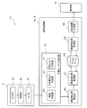
- FIG. 1 is a block diagram of a radar apparatus according to an embodiment of the present invention.
- FIG. 2 is a block diagram of a false image processing unit shown in FIG. 1. It is a figure which shows the echo waveform extracted by the echo waveform extraction part shown in FIG. 2 with the echo sample row
- FIG. 3 is a diagram schematically illustrating a radar device mounted on the ship, a sea area around the ship, and an echo image, and the tracking target candidate detected by the tracking target candidate detection unit illustrated in FIG. 2 will be described.
- FIG. It is a figure for demonstrating the echo image by which the determination whether it is a false image is performed by the false image determination part.
- FIG. 1 It is a figure which shows typically an example of the radar image produced
- FIG. 13 is a block diagram of a pulling wave echo processing unit shown in FIG. 12. It is a figure which shows the echo waveform extracted by the echo waveform extraction part shown in FIG. 13 with the echo sample row
- FIG. 14 is a diagram schematically illustrating a radar device mounted on the ship, a sea area around the ship, and an echo image, and the tracking target candidate detected by the tracking target candidate detection unit illustrated in FIG. 13 will be described.
- FIG. It is a figure for demonstrating the echo image by which it is determined whether it is a pulling wave by a pulling wave determination part. It is a figure which shows typically an example of the radar image produced
- FIG. 19 is a block diagram of a bird echo processing unit shown in FIG. 18. It is a figure which shows the echo waveform extracted by the echo waveform extraction part shown in FIG. 19 with the echo sample row
- FIG. 20 is a diagram schematically illustrating a radar device mounted on the ship, a sea area around the ship, and an echo image, and the tracking target candidate detected by the tracking target candidate detection unit illustrated in FIG. 19 will be described.
- FIG. It is a figure for demonstrating the echo image in which it is determined whether it is an echo image resulting from a bird by a bird echo determination part. It is a figure which shows typically an example of the radar image produced
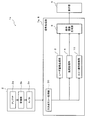
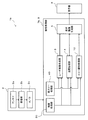
- FIG. 1 is a block diagram of a radar apparatus 1 according to an embodiment of the present invention.
- the radar apparatus 1 of this embodiment is, for example, a marine radar, and is mainly used for detecting a target such as another ship. Further, the radar apparatus 1 is configured to be able to track a target selected as a tracking target.
- a ship provided with the radar device 1 is referred to as “own ship”.
- the radar apparatus 1 determines whether or not the detected echo image is a specular reflection false image, and the echo level of the echo image determined to be a specular reflection false image is determined. Are reduced in the display screen and excluded from the tracking target.
- the radar device 1 includes an antenna unit 2, a signal processing unit 7 (signal processing device), and a display 6.
- the antenna unit 2 includes an antenna 2a, a receiver 2b, and an A / D converter 2c.
- the antenna 2a is a radar antenna capable of transmitting a pulsed radio wave (transmitted wave) having strong directivity.
- the antenna 2a is configured to receive a reflected wave from a target.
- the radar apparatus 1 measures the time from when a pulsed radio wave is transmitted until the reflected wave is received. Thereby, the radar apparatus 1 can detect the distance to the target.
- the antenna 2a is configured to be able to rotate 360 ° on a horizontal plane.
- the antenna 2a is configured to transmit and receive radio waves at each timing while changing the transmission direction of the pulsed radio waves (changing the antenna angle). With the above configuration, the radar apparatus 1 can detect a target on a plane around the ship over 360 °.
- the operation from the transmission of a pulsed radio wave to the transmission of the next pulsed radio wave is referred to as “sweep”.
- the operation of rotating the antenna 360 ° while transmitting / receiving radio waves is called “scan”.
- the receiving unit 2b detects and amplifies an echo signal obtained from the reflected wave received by the antenna 2a.
- the receiver 2b outputs the amplified echo signal to the A / D converter 2c.
- the A / D converter 2c samples an analog echo signal and converts it to digital data composed of a plurality of bits. This digital data is echo data.
- This echo data includes data for specifying the intensity of the echo signal obtained from the reflected wave received by the antenna 2a.
- the A / D conversion unit 2 c outputs the echo data to the signal processing unit 7.
- the signal processing unit 7 includes a false image processing unit 20, a radar image generation unit 3, a tracking processing unit 4, an echo identification processing unit 10, and a display image generation unit 5.
- the signal processing unit 7 includes a hardware processor 8 (for example, CPU, FPGA, etc.) and a device such as a nonvolatile memory.
- a hardware processor 8 for example, CPU, FPGA, etc.
- the CPU reads the program from the non-volatile memory and executes it, thereby causing the signal processing unit 7 to become the fake image processing unit 20, the radar image generation unit 3, the tracking processing unit 4, the echo identification processing unit 10, and the display image generation. It can function as the unit 5.
- FIG. 2 is a block diagram of the fake image processing unit 20 shown in FIG. As illustrated in FIG. 2, the false image processing unit 20 includes an echo waveform extraction unit 21, a tracking target candidate detection unit 22, and a false image determination unit 23.
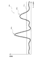
- FIG. 3 is a diagram showing the echo waveforms EW 1 and EW 2 extracted by the echo waveform extraction unit 21 shown in FIG. 2 together with the echo sample sequence ES 1 from which the echo waveforms EW 1 and EW 2 are extracted.
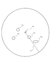
- FIG. 4 is a diagram schematically showing the radar apparatus 1 mounted on the ship, the sea area around the ship and an echo image, and is detected by the tracking target candidate detection unit 22 shown in FIG. It is a figure for demonstrating the tracking target candidate. Note that the echo sample array ES 1 shown in FIG. 3 is obtained along the straight line L 1 in FIG.
- the echo waveform extraction unit 21 is obtained at the time of one sweep on the coordinates where the horizontal axis is the sample number (corresponding to the distance from the ship position) and the vertical axis is the amplitude value of the echo.
- Echo waveforms EW 1 and EW 2 are extracted from the echo sample sequence ES 1 obtained by plotting a plurality of samples. Specifically, the echo waveform extraction unit 21 selects a plurality of sample points having an amplitude value equal to or greater than a predetermined threshold Thr 1 among a plurality of sample points constituting the echo sample sequence ES 1 and having consecutive sample numbers. Extracted as echo waveforms EW 1 and EW 2 . In the example shown in FIG. 3, two echo waveforms EW 1 and EW 2 are extracted. The echo waveform extraction unit 21 extracts the echo waveforms EW 1 and EW 2 for each echo sample sequence generated for each sweep.
- the tracking target candidate detection unit 22 calculates the geographical position of the echo waveform extracted by the echo waveform extraction unit 21 from the antenna orientation and the sampling rate when the sweep signal obtained by each sweep is acquired, and the echo waveform Those whose distances are within a predetermined value are grouped as echo waveforms from the same target, and detected as tracking target candidates.
- FIG. 4 shows an example in which echo images E 1 , E 2 , E 3 corresponding to each tracking target candidate are detected.
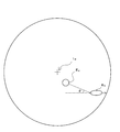
- FIG. 5 is a diagram for explaining an echo image in which it is determined whether or not it is a false image by the false image determination unit 23.
- the false image determination unit 23 determines whether or not each tracking target candidate is a false image for all the echo images E 1 , E 2 , and E 3 detected as tracking target candidates. The following describes an example in which the echo image E 1 is determined if it is an artifact.
- the false image determination unit 23 includes an orientation condition determination unit 24 and a distance condition determination unit 25.
- Orientation condition determining unit 24 determines whether or not another echo image on a straight line connecting the echo image E 1 to a position of the radar apparatus 1 (more precisely, the position of the antenna 2a) and determination target is present To do. In the following description, it referred to echo image E 1 and the first echo image E 1. The azimuth condition determination unit 24 determines that the first echo image is not a fake image when there is no other echo image on the straight line.
- Distance condition determination unit 25 the straight line to the other echo image (hereinafter for convenience, this echo image E 2 is referred to as a second echo image E 2) is the azimuth condition determining unit 24 is determined to be present In some cases, a predetermined determination is made. Specifically, the distance condition determination unit 25, a distance d1 from the first echo image E 1 to the second echo image E 2, other echo image from the second echo image (in the example shown in FIG. 5, A distance difference ⁇ d from the distance d2 is calculated up to the third echo image E 3 ), and the distance difference ⁇ d is compared with a predetermined threshold value.
- the distance condition determination unit 25 determines that the first echo image E 1 is not a specular reflection false image caused by the third echo image E 3 .
- the distance condition determination unit 25 when the distance difference ⁇ d is less than or equal to the threshold, determines that the first echo image E 1 is a specular artifacts F due to the third echo image E 3. (Specifically, the echo intensity at the position of the echo image E 1, and the position of the echo image E 1) data relating to echo image E 1 where it is determined that a false image F by the artifact determination unit 23, a radar image generation unit 3, the tracking processing unit 4 and the echo identification processing unit 10 are notified.
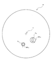
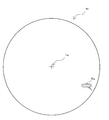
- FIG. 6 is a diagram schematically illustrating an example of the radar image Pr generated by the radar image generation unit 3.
- the radar image generator 3 Based on the echo data output from the A / D converter 2c, the radar image generator 3 generates a radar image Pr over 360 degrees in the horizontal direction with the ship position at the center. Further, the radar image generating unit 3 performs processing for reducing luminance of the determined echo image E 1 to be false image F by the artifact determination unit 23. Thereby, referring to FIG. 6, the false image F can be removed on the display screen.
- the dot density in FIG. 6 corresponds to the echo intensity of the reflected wave from the target. Specifically, a place where a high-intensity echo is observed is illustrated with a high-density dot, and a place where a low-intensity echo is observed is illustrated with a low-density dot.
- the tracking processing unit 4 is configured to identify a tracking target based on the echo data output from the A / D conversion unit 2c and to perform a tracking process for tracking the tracking target. Specifically, the tracking processing unit 4 calculates the coordinates of the tracking target and the predicted speed vector based on the velocity vector estimated from the coordinates of the tracking target at the time of past scanning. The tracking processing unit 4 outputs the calculated coordinates of the tracking target and the predicted speed vector to the display image generating unit 5.
- the tracking processing unit 4 excludes the echo image E 1 determined to be the false image F by the false image determination unit 23 from the tracking target. Thereby, the calculation load at the time of a tracking process can be reduced. Note that the processing performed by the tracking processing unit 4 is the same as the processing performed by a conventionally known tracking processing device, and thus detailed description thereof is omitted.
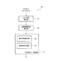
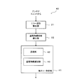
- FIG. 7 is a block diagram of the echo identification processing unit 10.
- the echo identification processing unit 10 extracts a tracking target based on the echo data output from the receiving unit 2b, and what kind of target the tracking target is (for example, a large vessel, a medium vessel, a small vessel, And the identification result is output to the display image generation unit 5.
- the echo identification processing unit 10 includes a feature vector generation unit 11, a storage unit 12, and an identification unit 13.
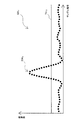
- FIG. 8 is a diagram illustrating an example of an echo waveform EW in which a feature vector is generated by the feature vector generation unit 11.
- the feature vector generation unit 11 includes an echo waveform excluding an echo waveform included in a false image of the echo waveform EW extracted from the echo sample sequence ES by the echo waveform extraction unit 21, that is, for each echo waveform of the tracking target.
- a plurality of feature amounts are calculated, and a feature vector is generated from the calculated plurality of feature amounts.
- the feature vector generation unit 11 first calculates first to fourth feature amounts C1 to C4 in order to generate a feature vector.
- the echo waveform EW has an amplitude value greater than or equal to a predetermined threshold Thr 1 among a plurality of sample points constituting the echo sample sequence ES, as in the case of the false image processing unit 20 described above, and the sample numbers are continuous. Consists of multiple sample points.
- the first feature amount C1 is the number of samples N1 at the rising portion in the echo waveform EW (in other words, the number of consecutive samples from the sample Smp1 exceeding the threshold Thr 1 to the sample Smp2 having the peak value Vp). ).
- the first feature amount C1 is calculated as a value normalized so that the number N1 of samples is within a range of 0 to 5.
- the second feature amount C2 is calculated based on the peak value Vp of the echo waveform EW.
- the second feature amount C2 is calculated as a value normalized so that the peak value Vp falls within the range of 0 to 5.
- Third feature amount C3 is (in other words, the number of consecutive samples from the sample Smp2 having a peak value Vp until the sample Smp3 below the threshold Thr 1) falling portion sample number N2 of the echo waveform EW are calculated based on .
- the third feature amount C3 is calculated as a value that is normalized so that the number of samples falls within the range of 0 to 5.
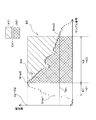
- the fourth feature value C4 each value subtracted from the peak value Vp of the amplitude values of the successive samples from the sample Smp2 having a peak value Vp until the sample Smp3 below the threshold Thr 1, the value A1 obtained by integrating the, from the sample Smp2 Calculation is performed based on a value (specifically, A1 / A2) obtained by dividing the amplitude value of the samples that continue to sample Smp3 by the integrated value A2. That is, the fourth feature amount is calculated based on a value obtained by dividing the area of the hatched portion in FIG. 8 by the area of the cross-hatched portion. In the present embodiment, the fourth feature amount C4 is calculated as a value normalized so that the value of A1 / A2 falls within the range of 0 to 5.
- FIG. 9 is a diagram showing a feature vector CV and a feature vector graph GCV generated from the feature vector CV.
- the feature vector generation unit 11 generates a feature vector CV in which the first to fourth feature amounts C1 to C4 calculated corresponding to each echo waveform are set as one set. Then, the feature vector generation unit 11 generates a feature vector graph GCV as shown in FIG. 9 from the feature vector CV.
- the feature vector graph G CV is a graph generated by plotting the feature amounts C1 to C4 on the orthogonal coordinate axes and connecting the feature amounts C1 to C4 adjacent in the circumferential direction with straight lines.
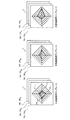
- FIG. 10 is a schematic diagram of a template TP (type data) stored in the storage unit 12.
- the template TP is a graph having the same coordinates as the feature vector graph GCV, and is a graph prepared in advance by experiments or the like.
- the template TP is a feature vector graph generated from a feature vector obtained by performing an experiment on a target whose shape is already known and obtaining the reflected wave.
- the template TP as an example For example, details large ships template TP L for identifying the tracked target object by the identification section 13 to be described later, the template for medium-sized vessels TP M, and small vessel template TP S, include ing.
- Each template TP is generated as an identification feature vector graph for identifying the size of the tracking target having the feature vector by being compared with the above-described feature vector graph GCV. ing. Note that the feature amount of each template TP shown in FIG. 10 is merely illustrated as an example, and is not related to the feature amount actually obtained by experiments or the like.
- the ship feature vector varies depending on the size of the ship. Specifically, for example, as an example, the maximum value of the echo waveform obtained from the echo of the large ship (that is, the feature amount C2) is larger than the maximum value of the echo waveform obtained from the echo of the small ship.
- the maximum value of the echo waveform obtained from the echo of the large ship that is, the feature amount C2
- the feature vector CV of the tracking target is compared with each template TP stored in the storage unit 12. By doing so, the size of the tracking target (ship) can be estimated.
- the feature vector of the ship varies depending on the direction of the other ship with respect to the own ship, that is, the direction of the other ship when viewed from the own ship.
- the storage unit 12 stores a plurality of feature vector templates TP that are different from each other depending on the direction of the other ship in each of the large ship, the medium ship, and the small ship.
- the identification unit 13 compares the feature vector graph GCV generated by the feature vector generation unit 11 with all the templates TP stored in the storage unit 12, and based on the comparison result, the ship as a tracking target Is identified (either a large vessel, a medium vessel, or a small vessel). More specifically, the identification unit 13 calculates the similarity between the feature vector graph GCV and each template TP, and the size of the ship indicated by the template TP having the highest similarity is the size of the ship. Identify.
- the identification unit 13 determines the position in the four-dimensional space specified by the feature amounts C1 to C4 constituting the tracking target feature vector graph G CV and the feature amounts C1tmp to C4tmp constituting the templates.
- the Euclidean distance from the position of the four-dimensional space specified by is calculated as the similarity.
- the identification part 13 identifies the magnitude
- the display image generation unit 5 is notified of the identification result in the identification unit 13 (that is, whether the tracking target is a large vessel, a medium vessel, or a small vessel).
- FIG. 11 is a diagram illustrating an example of the display image P generated by the display image generation unit 5, and is a diagram illustrating an image displayed on the display device 6.
- the display image generation unit 5 includes the radar image generated by the radar image generation unit 3, the coordinates and predicted velocity vectors of the tracking target notified from the tracking processing unit 4, and the tracking target in the echo identification processing unit 10. Based on the identification result, a display image P displayed on the display 6 is generated.
- the display image generation unit 5 indicates that the echo images E 2 and E 3 corresponding to the tracking target are tracking targets based on the coordinates of the tracking target notified from the tracking processing unit 4.
- the sizes of the markers MK2 and MK3 are determined based on the identification result of the tracking target identified by the identification unit 13.
- the echo image E 2 identified as medium-sized vessels, surrounded by a circular marker MK2 moderate radius
- echo image E 3 identified as small vessels, smaller radius Surrounded by a circular marker MK3.
- illustration in FIG. 11 is omitted, an echo image identified as a large ship is surrounded by a circular marker having a large radius. Thereby, the user can grasp
- the signal processing section 7 of the radar apparatus 1 includes a first position information of the echo image E 1, based on the second positional information of the echo image E 2, the first echo image E 1 Is a false image. That is, according to the signal processing unit 7, it is determined for each echo image whether or not the echo image to be determined is a false image. If it does so, there is no possibility of reducing to the echo intensity of the echo which is not a false image like patent document 1 mentioned above, and a false image can be discriminated correctly.
- the signal processing unit 7 can accurately determine that the echo image to be determined is a desired echo image (in the present embodiment, it is a false image).
- the signal processing unit 7 to position the second echo image E 2 between the antenna 2a and the first echo image E 1, and the distance from the first echo image E 1 to the second echo image E 2 the distance difference ⁇ d between the distance d 2 from d 1 and a second echo image E 2 to the third echo image E 3 is within the predetermined threshold, the condition, in the first echo image E 1 is false image F It is determined that there is. If the first echo image E 1 is specular artifacts of the third echo image E 3, and a second echo image E 2 is located between the antenna 2a and the first echo image E 1, and the distance d 1 and the distance d 2 and is substantially equal. That is, the signal processing unit 7 can more appropriately determine the false image F based on the characteristics of the false image F that is a specular reflection false image.
- the signal processing unit 7, echo image E 1 which is determined to be false image F is excluded from the tracking target. Thereby, the calculation load at the time of a tracking process can be reduced.
- the signal processing unit 7 the luminance in the determined display the screen of the echo image E 1 to be false image F is reduced. Thereby, the possibility that the user may misrecognize the false image F as a target can be reduced.
- a radar apparatus including the signal processing unit 7 that can accurately determine that the echo image to be determined is a desired echo image (in the case of the present embodiment, a false image) is provided. it can.
- the radar apparatus 1 can know the size of the tracking target from the size of the markers MK2 and MK3 displayed so as to be superimposed on the echo images E 2 and E 3 of the tracking targets.
- FIG. 12 is a block diagram of a radar apparatus 1a according to a modification.
- FIG. 13 is a block diagram of the wave echo processing unit 30 shown in FIG.
- the radar apparatus 1a according to the present modification is also configured as a marine radar, and can track a target selected as a tracking target, as in the case of the above embodiment.
- the signal processing unit 7a (signal processing device) of the radar apparatus 1a includes a subtraction echo processing unit 30 instead of the false image processing unit 20 of the above embodiment.
- the trailing wave echo processing unit 30 includes an echo waveform extracting unit 21, a tracking target candidate detection unit 22, and a trailing wave echo determination unit 31.
- FIG. 14 is a diagram showing the echo waveform EW 3 extracted by the echo waveform extraction unit 21 shown in FIG. 13 together with the echo sample string ES 2 from which the echo waveform EW 3 is extracted.
- FIG. 15 is a diagram schematically showing the radar apparatus 1a mounted on the ship, the sea area around the ship and the echo images E 4 and E 5 , which are detected by the tracking target candidate detection unit 22. It is a figure for demonstrating the tracking target candidate made. It is a figure for demonstrating the tracking target candidate detected by the tracking target candidate detection part 22.
- FIG. Incidentally, the echo sample sequence ES 2 shown in FIG. 14, is obtained along a straight line L2 in FIG. 15. Further, the broken line in FIG. 15 schematically shows the pulling wave of the echo image E5 (other ship).
- the echo waveform extraction unit 21 extracts the echo waveform EW 3 from the echo sample sequence ES 2 in the same manner as in the above embodiment.
- one echo waveform EW 3 is detected with reference to FIG.
- the echo sample train ES 2 includes a waveform EW a caused by a pulling wave of another ship.
- the peak value of the waveform EW a is equal to or less than the threshold value Thr 2 , it is not extracted as an echo waveform.
- the tracking target candidate detection unit 22 detects an echo image of the tracking target candidate in the same manner as in the above embodiment.
- FIG. 15 shows an example in which echo images E 4 and E 5 of two tracking target candidates are detected.
- FIG. 16 is a diagram for explaining an echo image in which it is determined whether or not it is a pulling wave by the pulling wave echo determination unit 31.
- the trailing wave echo determination unit 31 determines whether or not each tracking target candidate is a trailing wave for all the echo images E 4 and E 5 detected as the tracking target candidates.
- the echo image E 4 first echo image E 4
- the echo image E 4 is an echo image caused by a pulling wave.
- the trailing wave echo determination unit 31 includes a traveling direction estimation unit 32 and an angle condition determination unit 33.
- the traveling direction estimation unit 32 estimates the traveling direction of the echo image E 5 (second echo image E 5 ) other than the echo image E 4 for which it is determined whether or not it is a pulling wave. Specifically, the traveling direction estimating section 32, by performing the tracking processing for echo image E 5, estimates the traveling direction of the echo image E 5.
- the tracking process is a general process that has been conventionally known, and a description thereof will be omitted.
- Angle condition determining unit 33 is either a straight line along the traveling direction of the echo image E 5, a straight line connecting the echo image E 4 and the echo image E 5, the angle ⁇ which forms is included within a predetermined angular range not Determine whether. Specifically, the angle condition determination unit 33 determines whether or not the angle ⁇ is included in a predetermined angle range centered on a predetermined angle (for example, 19 °) (for example, ⁇ is 18 ° ⁇ Whether or not the condition of ⁇ ⁇ 20 ° is satisfied is determined. Then, the angle condition determination unit 33 determines that the echo image E 4 is not a pulling wave of the echo image E 5 when ⁇ ⁇ 18 ° or ⁇ ⁇ 20 °.
- the angle condition determination unit 33 determines that the echo image E 4 is a pulling wave of the echo image E 5 when 18 ° ⁇ ⁇ 20 °.
- Data relating to the angle condition determination unit 33 echo image E 4 it is determined that the echo image due to undertow by (specifically, the position of the echo image E 4, and the echo intensity at each position of the echo image E 4) Is notified to the radar image generation unit 3, the tracking processing unit 4, and the echo identification processing unit 10.
- FIG. 17 is a diagram schematically illustrating an example of a radar image Pr generated by the radar image generation unit 3 illustrated in FIG.
- the radar image generation unit 3 generates a radar image Pr over 360 degrees in the horizontal direction centered on the ship position based on the echo data output from the A / D conversion unit 2c. Generate. Further, the radar image generating unit 3 performs processing for reducing the echo level of the undertow echo determination unit 31 echo image E 4 it is determined that the echo image due to undertow by. Thus, with reference to FIG. 17, it can be removed on the display screen the echo image E 4 of undertow.
- the signal processing section 7a of the radar device 1a As described above, the signal processing section 7a of the radar device 1a according to this modification, the position information of the first echo image E 4, based on the position information of the second echo image E 5, first echo image E 4 There has been performed a determination of whether the echo image due to target object having different attributes from the second echo image E 5. In this way, for example, as in the radar device disclosed in Patent Document 2, it is possible to reduce the possibility that a wavefront velocity vector due to a pulling wave is erroneously detected as a target such as a ship.
- the signal processing unit 7a can accurately determine that the echo image to be determined is a desired echo image (in the case of this modification, it is an echo image caused by a pulling wave).
- first echo image E 4 pulls It is determined whether or not the echo image is caused by a wave. Thereby, it is possible to appropriately discriminate an echo image caused by the pulling wave based on the characteristic of the pulling wave that occurs on the side opposite to the traveling direction of the ship.
- the signal processing section 7a a straight line along the traveling direction of the second echo image E 5 (one-dot chain line in FIG. 16), a straight line connecting a first echo image E 4 and a second echo image E 5, forms angle ⁇ is, the condition that it is within a predetermined range, it is determined that the first echo image E 4 is echo image due to undertow.
- the echo image resulting from the pulling wave can be more appropriately determined based on the characteristic that the pulling wave of the ship is formed in the direction of a predetermined angle with respect to the straight line along the traveling direction of the ship.
- FIG. 18 is a block diagram of a radar apparatus 1b according to a modification.
- FIG. 19 is a block diagram of the bird echo processing unit 40 shown in FIG.
- the radar apparatus 1b according to the present modification is also configured as a marine radar and can track a target selected as a tracking target, as in the case of the above embodiment.
- the signal processing unit 7b (signal processing device) of the radar apparatus 1b includes a bird echo processing unit 40 in addition to the constituent elements of the signal processing unit 7 of the above embodiment.
- a bird echo processing unit 40 in addition to the constituent elements of the signal processing unit 7 of the above embodiment.
- the bird echo processing unit 40 has an echo waveform extraction unit 21, a tracking target candidate detection unit 22, and a bird echo determination unit 41 with reference to FIG.
- FIG. 20 is a diagram illustrating the echo waveform EW 4 extracted by the echo waveform extraction unit 21 together with the echo sample sequence ES 3 from which the echo waveform is extracted.
- FIG. 21 is a diagram schematically showing the radar apparatus 1b mounted on the ship, the sea area around the ship and the echo images E 6 to E 9, and the tracking target candidate detection shown in FIG.
- FIG. 10 is a diagram for explaining tracking target candidates detected by a unit 22; Incidentally, the echo sample sequence ES 3 shown in FIG. 20, is obtained along a straight line L3 in FIG. 21.
- Echo waveform extracting section 21 as in the case of the above embodiment, and extracts an echo waveform from the echo sample sequence ES 3.
- one echo waveform EW 4 is detected with reference to FIG.
- the tracking target candidate detection unit 22 detects an echo image of the tracking target candidate in the same manner as in the above embodiment.
- FIG. 21 shows an example in which echo images E 6 , E 7 , E 8 , E 9 of four tracking target candidates are detected.
- FIG. 22 is a diagram for explaining an echo image in which it is determined whether or not it is an echo image caused by a bird by the bird echo determination unit 41, and is a scan of the scan in which the echo image shown in FIG. 21 is obtained. It is a figure which shows the echo image obtained at the time of the next scan.
- the echo image shown in FIG. 21 (that is, the echo image obtained at the time of the scan before the echo image shown in FIG. 22 was obtained) is schematically shown by a broken line.
- the bird echo determination unit 41 determines whether or not each tracking target candidate is a bird for all the echo images E 6 to E 9 detected as the tracking target candidates.
- the bird echo determination unit 41 includes a tracking unit 42 and a tracking target selection unit 43.
- the tracking unit 42 performs a tracking process on each of the echo images E 6 to E 9 and calculates a movement vector of the echo image that can be tracked.
- the tracking process is a general process that has been conventionally known, and a description thereof will be omitted.
- the tracking target selection unit 43 targets all of the echo images (E 10 to E 12 in the example shown in FIG. 22) that could not be tracked by the tracking unit 42 described above. Which echo image is excluded from the tracking target is selected. Specifically, the tracking target sorting unit 43 ranks all the echo images E 10 to E 12 that could not be tracked, for example, in descending order of the maximum amplitude value of each echo image, for example, A predetermined number of echo images having a smaller maximum amplitude value are excluded from the tracking target. In the example shown in FIG. 22, the two echo images E 10 and E 11 having the smaller maximum amplitude value among all the echo images E 10 to E 12 that could not be tracked are recorded from the tracking target. Examples to be excluded are shown.
- the data (particularly to tracking target object sorting unit 43 echo image E 10, E 11, which is excluded from the tracking target object, the position of the echo image E 10, E 11, and the position of the echo image E 10, E 11 Is sent to the radar image generation unit 3, the tracking processing unit 4, and the echo identification processing unit 10.
- the reason why the echo images E 10 and E 11 excluded from the tracking target by the tracking target selection unit 43 are highly likely to be echo images caused by birds will be described.
- the degree of correlation of echo images of birds obtained at different times that is, different scans
- tracking processing cannot be performed in many cases. Therefore, an echo image that could not be subjected to the tracking process can be considered to be highly likely to be caused by a bird.
- the coincidence degree of the area of an echo image, etc. are mentioned.
- echo image E 12 in the case of the example shown in FIG. 22
- echo image E 12 has a higher echo intensity than the other echo image E 10, E 11.
- the echo intensity of the echo image of the ship is higher than the echo intensity of the echo image from the bird. Therefore, in this modification, the echo image E 12 higher than the echo image E 10, E 11 potentially echo images other due to the ship does not exclude from the tracking target object.
- FIG. 23 is a diagram schematically illustrating an example of a radar image Pr generated by the radar image generation unit 3 illustrated in FIG.
- the radar image generation unit 3 generates a radar image Pr over 360 degrees in the horizontal direction centered on the ship position based on the echo data output from the A / D conversion unit 2c. Generate. Further, the radar image generation unit 3 performs a process of reducing the echo levels of the echo images E 10 and E 11 that are determined to be echo images caused by birds by the bird echo determination unit 41. Thereby, referring to FIG. 23, echo images E 10 and E 11 caused by birds can be removed on the display screen.
- the radar apparatus 1b According to the present modification, tracking cannot be performed between different scans (that is, the movement vector cannot be calculated) among the echo images E 10 to E 12 .
- echo images caused by birds often have low correlation between different scans and cannot be tracked in many cases. Therefore, as in this modification, it is determined that at least one of the echo images E 10 to E 12 that could not be tracked is an echo image caused by a bird, so that the echo image caused by the bird is It can be determined appropriately according to the characteristics of the bird.
- the radar device 1b even echo images can not be performed tracking, (more specifically, the maximum amplitude value of the echo) echo strength for high echo image E 12 from the tracking target object Not excluded. This reduces the possibility of incorrectly echo image E 12 which can be due to the ship might exclude from the tracking target object.
- the bird echo determination unit 41 determines whether each tracking target candidate is a bird for all tracking target candidates detected by the tracking target candidate detection unit 22.
- the bird echo determination unit 41 excludes, from among the tracking target candidates, targets determined to be false images by the false image determination unit 23 from the determination target, and the remaining targets (false) It may be determined whether the first echo image after image exclusion) is an echo caused by a bird. That is, after performing the false image determination by the false image determination unit 23, the bird echo determination by the bird echo determination unit 41 may be performed. Thereby, since the determination object in the bird echo determination part 41 can be narrowed down appropriately, the calculation load concerning the bird echo determination part 41 can be reduced.
- FIG. 24 is a block diagram of a radar apparatus 1c according to a modification.
- the radar apparatus 1c according to this modification detects a target candidate echo that is an echo image included in the echo image and is a target candidate to be detected.
- the radar apparatus 1c is configured to exclude unnecessary targets from the target candidate echoes and to display the remaining echo images with emphasis as target echoes.
- the radar apparatus 1c includes the false image determination unit 23, the trailing wave echo determination unit 31, and the bird echo determination unit 41 described in the above-described embodiments and modifications.
- the radar device 1c is caused by an echo image determined to be a false image by the false image determination unit 23, an echo image determined to be caused by a pulling wave by the trailing wave echo determination unit 31, and a bird caused by the bird echo determination unit 41. Then, the determined echo image is set as an unnecessary target, and these unnecessary targets are not highlighted.
- the radar apparatus 1c includes an antenna unit 2, a signal processing unit 7c (signal processing apparatus), and a display 6. Since the antenna unit 2 and the display device 6 are the same as those in the above embodiment, the description thereof is omitted.
- the signal processing unit 7 c includes a target candidate detection unit 15, an unnecessary target detection unit 16, an inter-scan correlation unit 17, and a display image generation unit 5 a having a target echo enhancement unit 18.
- the target candidate detection unit 15 performs substantially the same operation as the tracking target candidate detection unit 22 described in the above embodiment. Specifically, the target candidate detection unit 15 uses the antenna when the sweep signal obtained by each sweep is obtained from the geographical positions of a plurality of echo waveforms extracted from the echo sample sequence obtained for each sweep. Calculate from azimuth and sampling rate. Then, the target candidate detection unit 15 groups the echo waveforms whose distances are within a predetermined value as echo waveforms from the same target, and detects them as target candidates.
- the unnecessary target detection unit 16 includes a false image determination unit 23, a trailing wave echo determination unit 31, and a bird echo determination unit 41.
- the unnecessary target detection unit 16 includes an echo image that is determined to be a false image by the false image determination unit 23, an echo image that is determined to be caused by the pulling wave by the trailing wave echo determination unit 31, and a bird that is determined by the bird echo determination unit 41.
- An echo image determined to be caused by is detected as an unnecessary target.
- the configurations of the fake image determination unit 23, the trailing wave echo determination unit 31, and the bird echo determination unit 41 are the same as those described in the above embodiment and each modification, and thus the description thereof is omitted.
- the inter-scan correlation unit 17 determines an echo image having high correlation between scans as a stop target. Specifically, for example, as an example, the inter-scan correlation unit 17 selects two echo images having similar positions and echo intensities from among echo images included in two temporally continuous echo images, as a stop target. Is determined.
- the target echo enhancement unit 18 enhances the echo images of all targets excluding unnecessary targets from the target candidates and stop targets detected by the target candidate detection unit 15. For example, the target echo enhancing unit 18 enhances the echo image by making the luminance of the echo image higher than the luminance corresponding to the echo intensity of the actually obtained echo image.
- the display image generation unit 5a generates an echo image including the echo image emphasized in this way as a display image displayed on the display. The echo image emphasized as described above is displayed on the echo image displayed on the display device 6.
- the remaining target echoes excluding unnecessary targets from the target candidates detected by the target candidate detection unit are highlighted and displayed.
- a target false image, pulling wave, etc.
- FIG. 25 is a block diagram of a radar apparatus 1d according to a modification.
- the radar apparatus 1d according to the present modification is configured to exclude an echo image caused by an unnecessary target from the detected echo image and detect a fixed object (for example, land, quay, etc.) from the remaining echo image. Has been.
- information for example, position, size, etc. regarding the detected fixed object is stored in a database, and a map around the ship is generated and displayed based on the information.
- the radar device 1d includes an antenna unit 2, a signal processing unit 7d (signal processing device), and a display 6. Since the antenna unit 2 and the display device 6 are the same as those in the above embodiment, the description thereof is omitted.
- the signal processing unit 7d includes an unnecessary target detection unit 16, a fixed object position estimation unit 26, a fixed object position registration unit 27, a database 28, a fixed object position acquisition unit 29, and a display image generation unit 5b. ing. Among these, the unnecessary target detection unit 16 is the same as the modification described with reference to FIG.
- the fixed object position estimation unit 26 detects an unnecessary target (specifically, a false image, a pulling wave, and a bird) detected by the unnecessary target detection unit 16 from an echo image included in an echo obtained from a reflected wave of the transmission wave. ) Is excluded. Then, the fixed object position estimation unit 26 detects an echo image caused by the fixed object from the remaining echo images (hereinafter, this echo image is referred to as a fixed object candidate echo image). For example, as an example, the fixed object position estimation unit 26 performs a tracking process on the fixed object candidate echo image, and uses an echo caused by a moving target (such as another ship) as an obstacle echo. And the fixed object position estimation part 26 detects fixed objects, such as a quay, by excluding the said obstacle echo from the fixed object candidate echo image mentioned above.
- an unnecessary target specifically, a false image, a pulling wave, and a bird
- the fixed object position estimation unit 26 estimates the absolute position of the detected fixed object.
- the fixed object position estimation unit 26 is configured to obtain the absolute position of the ship obtained from a positioning device (not shown) such as a GPS mounted on the ship, and the relative position of the fixed object with reference to the ship. Based on the above, the absolute position of the detected fixed object is estimated.
- the fixed object position registration unit 27 registers the absolute position of the fixed object estimated by the fixed object position estimation unit 26 in the database 28.
- the database 28 stores and accumulates the absolute position of the fixed object registered by the fixed object position registration unit 27.
- the fixed object position acquisition unit 29 acquires information on the position of the fixed object included in the sea area where the image is generated by the display image generation unit 5b from the database 28.
- the display image generation unit 5b generates a display image to be displayed on the display device 6. Specifically, in the display image generated by the display image generation unit 5b, the fixed object is displayed at a corresponding position in the display image based on the position information of the fixed object acquired by the fixed object position acquisition unit 29.
- a simple map is obtained based on the information related to the fixed object detected in the sea area where the ship on which the radar apparatus 1d is mounted navigates. Can be generated. Thereby, a map around the route can be obtained without preparing map data in advance.
- map information when map data is prepared in advance, the map information can be replaced with the latest information detected by the radar apparatus 1d. Thereby, map data can be updated at any time and the newest map can be obtained.
- the signal processing unit 7d can detect a fixed object after removing an unnecessary target, the unnecessary target (for example, a false image) can be prevented from being reflected in map information. . Thereby, an accurate map can be obtained.
Landscapes
- Engineering & Computer Science (AREA)
- Radar, Positioning & Navigation (AREA)
- Remote Sensing (AREA)
- Physics & Mathematics (AREA)
- Computer Networks & Wireless Communication (AREA)
- General Physics & Mathematics (AREA)
- Electromagnetism (AREA)
- Radar Systems Or Details Thereof (AREA)
Abstract
【課題】判定対象となるエコー像が所望のエコー像であることを正確に判別する。 【解決手段】送信波の反射波から得られたエコーの中に含まれる第1エコー像(E1)の位置情報と、エコーの中に含まれる第2エコー像(E2)の位置情報とに基づき、第1エコー像(E1)が偽像(F)であるか否かの判定、及び、第1エコー像が第2エコー像とは異なる属性を有する物標に起因するエコー像であるか否かの判定、の少なくとも一方を行う判定部を有する信号処理装置を構成する。
Description
本発明は、エコーの中から所望のエコー像を判別する信号処理装置、及び該信号処理装
置を備えたレーダ装置に関する。
置を備えたレーダ装置に関する。
従来、送信波の反射波から得られたエコーの中から所望のエコー像を判別する信号処理装置、及びその信号処理装置を備えたレーダ装置が知られている。例えば、特許文献1には、所望のエコー像としての偽像を低減するレーダ装置が開示されている。このレーダ装置では、エコー画像内における所定の領域を偽像領域とし、その偽像領域内のエコー像のエコーレベルを低減している。
また、特許文献2には、所望のエコー像として引き波を検出するレーダ装置が開示されている。引き波とは、特許文献2の図9を参照して、航行する船舶の後方に生じる一対の直線状の波である。特許文献2のレーダ装置では、海上の各地点における波頭速度ベクトルが導出される。そして、それらの波頭速度ベクトルのうち、互いに反対方向に進行し且つ周囲の波頭速度ベクトルよりも所定値以上大きい一対の波頭速度ベクトルを、引き波に起因する波頭速度ベクトルとして検出する。
しかし、上記特許文献1に示すレーダ装置では、例えば偽像領域内に偽像でないエコー像が含まれている場合、そのエコー像についてもエコーレベルが低減されてしまう。そうすると、探知対象となる物標を正確に探知できなくなるおそれが生じる。
また、上記特許文献2に示すレーダ装置では、例えば実際に引き波を構成する波頭速度ベクトルであっても、引き波である一対の波頭速度ベクトルのうちの一方の速度ベクトルの大きさが所定値未満である場合には、その一対の波頭速度ベクトルは波頭速度ベクトルとして検出されず、残りの波頭速度ベクトルが、例えば他の物標として誤検出されてしまうおそれがある。
本発明は、上記課題を解決するためのものであり、その目的は、判定対象となるエコー像が所望のエコー像であることを正確に判別することである。
(1)上記課題を解決するため、本発明のある局面に係る信号処理装置は、送信波の反射波から得られたエコーの中に含まれる第1エコー像の位置情報と、前記エコーの中に含まれる第2エコー像の位置情報とに基づき、前記第1エコー像が偽像であるか否かの判定、及び、前記第1エコー像が前記第2エコー像とは異なる属性を有する物標に起因するエコー像であるか否かの判定、の少なくとも一方を行う判定部、を備えている。
なお、「属性」とは、本明細書中においては、各物標が有する大まかな特徴を指す用語として用いており、例えば一例として、船舶と海上に発生する波とは属性が異なる。一方、例えば一例として、大型船舶の属性と小型船舶の属性とは同じであり、曳航船の属性と被曳航船の属性とは同じである。
(2)前記判定部は、前記第1エコー像の方位及び前記第2エコー像の方位に基づき、前記第1エコー像が偽像であるか否かを判定する偽像判定部を有している。
(3)前記偽像判定部は、前記送信波の送波位置と前記第1エコー像との間に前記第2エコー像が位置すること、及び、前記第1エコー像から前記第2エコー像までの距離と前記第2エコー像から第3エコー像までの距離との差が所定の閾値以内であること、を条件として、前記第1エコー像が偽像であると判定する。
(4)前記判定部は、前記第2エコー像の進行方向に基づき、前記第1エコー像が引き波に起因するエコー像であるか否かを判定する引き波エコー判定部、を有している。
(5)前記引き波エコー判定部は、前記第2エコー像の進行方向に沿う直線と、前記第2エコー像と前記第1エコー像とを結ぶ直線と、がなす角度が、所定の角度範囲内に含まれていることを条件として、前記第1エコー像が引き波に起因するエコー像であると判定する。
(6)前記判定部は、追尾を行うことができなかった物標の中から少なくとも1つの物標を鳥であると判定する鳥エコー判定部、を有している。
(7)前記鳥エコー判定部は、追尾を行うことができなかった前記物標が鳥であるか否かの判定を、該物標のエコー強度に基づいて行う。
(8)前記判定部は、前記第1エコー像が偽像であるか否かの判定を行い、少なくとも1つの前記第1エコー像のうち偽像であると判定された第1エコー像を除いた偽像除外後エコー像を対象として、該偽像除外後エコー像が前記第2エコー像とは異なる属性を有する物標に起因するエコー像であるか否かの判定を行う。
(9)前記信号処理装置は、前記反射波から得られた前記エコーに含まれるエコー像から、前記偽像判定部で偽像であると判定された前記第1エコー像、及び前記引き波エコー判定部で引き波に起因するエコー像であると判定された前記第1エコー像の少なくとも一方を除外して、残りのエコー像を追尾物標として決定し該追尾物標を追尾する追尾処理部、を更に備えている。
(10)前記信号処理装置は、前記偽像判定部で偽像であると判定された前記第1エコー像、及び前記引き波エコー判定部で引き波に起因するエコー像であると判定された前記第1エコー像の少なくとも一方のエコー強度が低減されたエコー画像を生成する表示画像生成部、を更に備えている。
(11)前記信号処理装置は、前記反射波から得られた前記エコーに含まれるエコー像から、前記偽像判定部で偽像であると判定された前記第1エコー像、及び前記引き波判定部で引き波に起因するエコー像であると判定された前記第1エコー像の少なくとも一方を除外して、残りのエコー像を強調するエコー強調部を有し、該エコー強調部で強調された前記残りのエコー像を含むエコー画像を生成する表示画像生成部、を更に備えている。
(12)前記信号処理装置は、前記反射波から得られた前記エコーに含まれるエコー像から、前記偽像判定部で偽像であると判定された前記第1エコー像、及び前記引き波判定部で引き波に起因するエコー像であると判定された前記第1エコー像の少なくとも一方を除外して、残りのエコー像の中から固定物に起因するエコー像を検出して該固定物の位置を推定する固定物位置推定部と、前記固定物位置推定部で推定された前記固定物の位置を記憶するデータベースと、前記データベースに記憶されている前記固定物の位置が反映された画像を生成する表示画像生成部と、を更に備えている。
(13)上記課題を解決するため、本発明のある局面に係るレーダ装置は、上述したいずれかの信号処理装置を備えている。
本発明によれば、判定対象となるエコー像が所望のエコー像であることを正確に判別できる。
以下、本発明に係る信号処理装置としての信号処理部7を有するレーダ装置1の実施形態について図面を参照しつつ説明する。
図1は、本発明の実施形態に係るレーダ装置1のブロック図である。本実施形態のレーダ装置1は、例えば、舶用レーダであって、主に他船等の物標の探知に用いられる。また、レーダ装置1は、追尾物標として選択された物標を追尾することが可能に構成されている。尚、以下では、レーダ装置1が備えられている船舶を「自船」という。
そして、レーダ装置1では、詳細は後述するが、検出されたエコー像が鏡面反射偽像であるか否かが判定され、鏡面反射偽像であると判定されたエコー像については、そのエコーレベルが表示画面中において低減されるとともに、追尾物標から除外される。
図1に示すように、レーダ装置1は、アンテナユニット2と、信号処理部7(信号処理装置)と、表示器6と、を備えている。
アンテナユニット2は、アンテナ2aと、受信部2bと、A/D変換部2cと、を含んでいる。
アンテナ2aは、指向性の強いパルス状電波(送信波)を送波可能なレーダアンテナである。また、アンテナ2aは、物標からの反射波を受波するように構成されている。レーダ装置1は、パルス状電波を送波してから反射波を受波するまでの時間を測定する。これにより、レーダ装置1は、物標までの距離を検出することができる。アンテナ2aは、水平面上で360°回転可能に構成されている。アンテナ2aは、パルス状電波の送波方向を変えながら(アンテナ角度を変えながら)、電波の送受波を各タイミングで行うように構成されている。以上の構成で、レーダ装置1は、自船周囲の平面上の物標を、360°にわたり探知することができる。
なお、以下の説明では、パルス状電波を送波してから次のパルス状電波を送波するまでの動作を「スイープ」という。また、電波の送受信を行いながらアンテナを360°回転させる動作を「スキャン」と呼ぶ。
受信部2bは、アンテナ2aで受波した反射波から得られるエコー信号を検波して増幅する。受信部2bは、増幅したエコー信号を、A/D変換部2cへ出力する。A/D変換部2cは、アナログ形式のエコー信号をサンプリングし、複数ビットからなるデジタルデータに変換する。このデジタルデータは、エコーデータである。このエコーデータは、アンテナ2aが受波した反射波から得られたエコー信号の強度を特定するデータを含んでいる。A/D変換部2cは、エコーデータを、信号処理部7へ出力する。
[信号処理部の構成]
信号処理部7は、偽像処理部20と、レーダ画像生成部3と、追尾処理部4と、エコー識別処理部10と、表示画像生成部5とを有している。
信号処理部7は、偽像処理部20と、レーダ画像生成部3と、追尾処理部4と、エコー識別処理部10と、表示画像生成部5とを有している。
信号処理部7は、ハードウェア・プロセッサ8(例えば、CPU、FPGA等)及び不揮発性メモリ等のデバイスで構成される。例えば、CPUが不揮発性メモリからプログラムを読み出して実行することにより、信号処理部7を、偽像処理部20、レーダ画像生成部3、追尾処理部4、エコー識別処理部10、及び表示画像生成部5として機能させることができる。
図2は、図1に示す偽像処理部20のブロック図である。偽像処理部20は、図2に示すように、エコー波形抽出部21と、追尾物標候補検出部22と、偽像判定部23とを有している。
図3は、図2に示すエコー波形抽出部21によって抽出されたエコー波形EW1,EW2を、該エコー波形EW1,EW2が抽出されたエコーサンプル列ES1とともに示す図である。また、図4は、自船に搭載されたレーダ装置1と、自船周辺の海域及びエコー像とを模式的に示す図であって、図2に示す追尾物標候補検出部22によって検出される追尾物標候補について説明するための図である。なお、図3に示すエコーサンプル列ES1は、図4における直線L1に沿って得られたものである。
エコー波形抽出部21は、図3に示すように、横軸をサンプル番号(自船位置からの距離に対応)、縦軸をエコーの振幅値とする座標上に、1回のスイープ時に得られる複数のサンプルをプロットして得られたエコーサンプル列ES1の中から、エコー波形EW1,EW2を抽出する。具体的には、エコー波形抽出部21は、エコーサンプル列ES1を構成する複数のサンプル点のうち所定の閾値Thr1以上の振幅値を有し且つサンプル番号が連続する複数のサンプル点を、エコー波形EW1,EW2として抽出する。図3に示す例では、2つのエコー波形EW1,EW2が抽出される。エコー波形抽出部21は、スイープ毎に生成されるエコーサンプル列毎に、エコー波形EW1,EW2を抽出する。
追尾物標候補検出部22は、エコー波形抽出部21で抽出されたエコー波形の地理的な位置を、各スイープで得られるスイープ信号を取得したときのアンテナ方位及びサンプリングレートから算出し、エコー波形間の距離が所定値以内となるもの同士を同一物標からのエコー波形としてグループ化し、それを追尾物標候補として検出する。図4では、各追尾物標候補に対応するエコー像E1,E2,E3が検出された例が示されている。
図5は、偽像判定部23によって偽像であるか否かの判定が行われるエコー像について説明するための図である。偽像判定部23は、追尾物標候補として検出されたエコー像E1,E2,E3の全てを対象として、各追尾物標候補が偽像であるか否かを判定する。以下では、エコー像E1が偽像であるか否かについて判定される例について説明する。
偽像判定部23は、方位条件判定部24と、距離条件判定部25とを有している。
方位条件判定部24は、レーダ装置1の位置(より正確にはアンテナ2aの位置)と判定対象となるエコー像E1とを繋ぐ直線上に他のエコー像が存在しているか否かを判定する。なお、以下では、エコー像E1を第1エコー像E1と称する。方位条件判定部24は、その直線上に他のエコー像が存在していない場合、偽像判定部23は、前記第1エコー像が偽像でないと判定する。
距離条件判定部25は、前記直線上に他のエコー像(以下では便宜上、このエコー像E2を第2エコー像E2と称する)が存在していると前記方位条件判定部24が判定した場合に、所定の判定を行う。具体的には、距離条件判定部25は、第1エコー像E1から第2エコー像E2までの距離d1と、前記第2エコー像から他のエコー像(図5に示す例の場合、第3エコー像E3)まで距離d2との距離差Δdを算出し、その距離差Δdを所定の閾値と比較する。そして、距離条件判定部25は、距離差Δdが閾値よりも大きい場合には、第1エコー像E1が第3エコー像E3に起因する鏡面反射偽像でないと判定する。一方、距離条件判定部25は、距離差Δdが閾値以下の場合には、第1エコー像E1が第3エコー像E3に起因する鏡面反射偽像Fであると判定する。偽像判定部23によって偽像Fと判定されたエコー像E1に関するデータ(具体的には、エコー像E1の位置、及びエコー像E1の各位置におけるエコー強度)は、レーダ画像生成部3、追尾処理部4、及びエコー識別処理部10へ通知される。
図6は、レーダ画像生成部3によって生成されるレーダ画像Prの一例を模式的に示す図である。レーダ画像生成部3は、A/D変換部2cから出力されたエコーデータに基づき、自船位置を中心とした水平方向の360度に亘るレーダ画像Prを生成する。また、レーダ画像生成部3は、偽像判定部23によって偽像Fであると判定されたエコー像E1の輝度を低減する処理を行う。これにより、図6を参照して、偽像Fを表示画面上において除去することができる。なお、図6におけるドットの密度は、物標からの反射波のエコー強度に対応している。具体的には、高強度のエコーが観測された場所は密度が高いドットで図示され、低強度のエコーが観測された場所は密度が低いドットで図示されている。
追尾処理部4は、A/D変換部2cから出力されたエコーデータに基づいて追尾物標を特定し、当該追尾物標を追尾する追尾処理を行うように構成されている。具体的には、追尾処理部4は、過去のスキャン時における追尾物標の座標から推測される速度ベクトルに基づき、追尾物標の座標、及び予測速度ベクトルを算出する。追尾処理部4は、算出した追尾物標の座標及び予測速度ベクトルを、表示画像生成部5へ出力する。
なお、追尾処理部4は、偽像判定部23によって偽像Fであると判定されたエコー像E1については、追尾物標から除外する。これにより、追尾処理時の演算負荷を軽減することができる。なお、追尾処理部4が行う処理は、従来から知られている追尾処理装置によって行われる処理と同様であるため、詳細な説明を省略する。
図7は、エコー識別処理部10のブロック図である。エコー識別処理部10は、受信部2bから出力されたエコーデータに基づいて追尾物標を抽出するとともに、当該追尾物標がどのような物標か(例えば、大型船舶、中型船舶、小型船舶、のいずれか)を識別し、その識別結果を表示画像生成部5に出力する。エコー識別処理部10は、図7に示すように、特徴ベクトル生成部11と、記憶部12と、識別部13とを備えている。
図8は、特徴ベクトル生成部11によって特徴ベクトルの生成が行われるエコー波形EWの一例を示す図である。特徴ベクトル生成部11は、エコー波形抽出部21によってエコーサンプル列ESから抽出されたエコー波形EWのうち、偽像のエコー像に含まれるエコー波形を除くエコー波形、すなわち追尾物標のエコー波形毎に複数の特徴量を算出し、算出された複数の特徴量から特徴ベクトルを生成する。特徴ベクトル生成部11は、特徴ベクトルを生成するために、まず、第1から第4の特徴量C1~C4を算出する。なお、エコー波形EWは、上述した偽像処理部20の場合と同様、エコーサンプル列ESを構成する複数のサンプル点のうち所定の閾値Thr1以上の振幅値を有し且つサンプル番号が連続する複数のサンプル点で構成される。
図8を参照して、第1特徴量C1は、エコー波形EWにおける立ち上がり部分のサンプル数N1(言い換えると、閾値Thr1を超えたサンプルSmp1からピーク値Vpを有するサンプルSmp2まで連続するサンプルの数)に基づいて算出される。本実施形態では、第1特徴量C1は、該サンプルの数N1が0から5の範囲内に収まるように規格化された値として算出される。
第2特徴量C2は、エコー波形EWのピーク値Vpに基づいて算出される。本実施形態では、第2特徴量C2は、ピーク値Vpが0から5の範囲内に収まるように規格化された値として算出される。
第3特徴量C3は、エコー波形EWにおける立ち下がり部分のサンプル数N2(言い換えると、ピーク値Vpを有するサンプルSmp2から閾値Thr1を下回るサンプルSmp3まで連続するサンプルの数)に基づいて算出される。本実施形態では、第3特徴量C3は、該サンプルの数が0から5の範囲内に収まるように規格化された値として算出される。
第4特徴量C4は、ピーク値Vpを有するサンプルSmp2から閾値Thr1を下回るサンプルSmp3まで連続するサンプルのそれぞれの振幅値をピーク値Vpから減算した値、を積分した値A1を、サンプルSmp2からサンプルSmp3まで連続するサンプルの振幅値を積分した値A2で除算した値(具体的には、A1/A2)に基づいて算出される。すなわち、第4特徴量は、図8における斜線ハッチング部分の面積を、クロスハッチング部分の面積で除算した値に基づいて算出される。本実施形態では、第4特徴量C4は、A1/A2の値が0から5の範囲内に収まるように規格化された値として算出される。
図9は、特徴ベクトルCVと、該特徴ベクトルCVから生成される特徴ベクトルグラフGCVとを示す図である。特徴ベクトル生成部11は、各エコー波形に対応して算出される第1から第4の特徴量C1~C4を1つの組とした特徴ベクトルCVを生成する。そして、特徴ベクトル生成部11は、この特徴ベクトルCVから、図9に示すような特徴ベクトルグラフGCVを生成する。特徴ベクトルグラフGCVは、直交座標の軸上に各特徴量C1~C4がプロットされ、周方向に隣接する特徴量C1~C4同士が直線で結ばれることにより生成されたグラフである。
図10は、記憶部12が記憶しているテンプレートTP(種別データ)の模式図である。テンプレートTPは、特徴ベクトルグラフGCVと同じ座標を有しているグラフであって、実験等によって予め準備されたグラフである。具体的には、テンプレートTPは、既にその形状が分かっている物標に対して実験を行い、その反射波から得られた特徴ベクトルから生成された特徴ベクトルグラフである。テンプレートTPには、例えば一例として、詳しくは後述する識別部13によって追尾物標を識別するための大型船舶用テンプレートTPL、中型船舶用テンプレートTPM、及び小型船舶用テンプレートTPS、が含まれている。各テンプレートTPは、上述した特徴ベクトルグラフGCVと比較されることにより、当該特徴ベクトルを有する追尾物標がいずれの大きさの船舶であるかを識別するための識別用特徴ベクトルグラフとして生成されている。なお、図10で示す各テンプレートTPの特徴量は、単に一例として図示したものに過ぎず、実際に実験等によって得られた特徴量とは無関係である。
船舶の特徴ベクトルは、船舶の大きさによって異なる。具体的には、例えば一例として、大型船舶のエコーから得られるエコー波形の最大値(すなわち特徴量C2)は、小型船舶のエコーから得られるエコー波形の最大値よりも大きくなる。このように、船舶の大きさによって互いに異なる特徴ベクトルのテンプレートTPを、船舶の大きさ毎に予め準備し、追尾物標の特徴ベクトルCVを、記憶部12で記憶されている各テンプレートTPと比較することにより、追尾物標(船舶)の大きさを推定することができる。
また、船舶の特徴ベクトルは、自船に対する他船の向き、すなわち、自船から視た場合における他船の向きによっても異なる。この点につき、記憶部12は、他船の向きによって互いに異なる特徴ベクトルのテンプレートTPを、大型船舶、中型船舶、及び小型船舶のそれぞれにおいて、複数、記憶している。
識別部13は、特徴ベクトル生成部11によって生成された特徴ベクトルグラフGCVを、記憶部12に記憶されている全てのテンプレートTPと比較し、その比較結果に基づいて、追尾物標としての船舶の大きさ(大型船舶、中型船舶、或いは小型船舶のいずれか)を識別する。やや詳しくは、識別部13は、特徴ベクトルグラフGCVと各テンプレートTPとの類似度をそれぞれ算出し、最も類似度が高いテンプレートTPが示す船舶の大きさを、その船舶の大きさであると識別する。
具体的には、識別部13は、追尾物標の特徴ベクトルグラフGCVを構成する各特徴量C1~C4によって特定される4次元空間の位置と、各テンプレートを構成する各特徴量C1tmp~C4tmpによって特定される4次元空間の位置と、のユークリッド距離を、類似度として算出する。そして、識別部13は、そのユークリッド距離が最も小さいテンプレートが示す大きさを、追尾物標の大きさであると識別する。識別部13での識別結果(すなわち、追尾物標が大型船舶であるか、中型船舶であるか、或いは小型船舶であるか)は、表示画像生成部5に通知される。
図11は、表示画像生成部5によって生成される表示画像Pの一例を示す図であって、表示器6に表示される画像を示す図である。表示画像生成部5は、レーダ画像生成部3で生成されたレーダ画像と、追尾処理部4から通知された追尾物標の座標及び予測速度ベクトルと、エコー識別処理部10での追尾物標の識別結果と、に基づき、表示器6で表示される表示画像Pを生成する。
具体的には、表示画像生成部5は、追尾処理部4から通知された追尾物標の座標に基づき、追尾物標に対応するエコー像E2,E3が追尾物標であることを示すための当該エコー像E2,E3を囲むマーカーMK2,MK3の画像を生成する。このマーカーMK2,MK3の大きさは、識別部13によって識別された追尾物標の識別結果に基づいて決定される。図11に示す表示画像Pでは、中型船舶と識別されたエコー像E2は、半径が中くらいの円形状のマーカーMK2によって囲まれ、小型船舶と識別されたエコー像E3は、半径が小さい円形状のマーカーMK3によって囲まれる。なお、図11での図示は省略するが、大型船舶と識別されたエコー像については、半径が大きい円形状のマーカーによって囲まれる。これにより、ユーザは、各船舶の大きさを容易に把握することができる。
[効果]
以上のように、本実施形態に係るレーダ装置1の信号処理部7は、第1エコー像E1の位置情報と、第2エコー像E2の位置情報とに基づき、第1エコー像E1が偽像であると判定している。すなわち、信号処理部7によれば、判定対象となるエコー像が偽像であるか否かの判定を、エコー像毎に行っている。そうすると、上述した特許文献1のように偽像でないエコーのエコー強度まで低減してしまうおそれがなくなり、偽像を正確に判別することができる。
以上のように、本実施形態に係るレーダ装置1の信号処理部7は、第1エコー像E1の位置情報と、第2エコー像E2の位置情報とに基づき、第1エコー像E1が偽像であると判定している。すなわち、信号処理部7によれば、判定対象となるエコー像が偽像であるか否かの判定を、エコー像毎に行っている。そうすると、上述した特許文献1のように偽像でないエコーのエコー強度まで低減してしまうおそれがなくなり、偽像を正確に判別することができる。
従って、信号処理部7では、判定対象となるエコー像が所望のエコー像であること(本実施形態の場合、偽像であること)を正確に判別できる。
また、信号処理部7では、第1エコー像E1の方位及び第2エコー像E2の方位に基づき、第1エコー像E1が偽像であるか否かの判定が行われている。第1エコー像E1が鏡面反射偽像であれば、第1エコー像E1は第2エコー像E2と概ね同じ方位に存在することになる。すなわち、信号処理部7によれば、鏡面反射偽像である偽像Fの特性に基づき、偽像Fを適切に判別することができる。
また、信号処理部7では、アンテナ2aと第1エコー像E1との間に第2エコー像E2が位置すること、及び、第1エコー像E1から第2エコー像E2までの距離d1と第2エコー像E2から第3エコー像E3までの距離d2との距離差Δdが所定の閾値以内であること、を条件として、第1エコー像E1が偽像Fであると判定される。第1エコー像E1が第3エコー像E3の鏡面反射偽像であれば、アンテナ2aと第1エコー像E1との間に第2エコー像E2が位置し、且つ距離d1と距離d2とが概ね等しくなる。すなわち、信号処理部7によれば、鏡面反射偽像である偽像Fの特性に基づき、偽像Fをより適切に判別することができる。
また、信号処理部7では、偽像Fであると判定されたエコー像E1が追尾対象から除外される。これにより、追尾処理時の演算負荷を軽減することができる。
また、信号処理部7では、偽像Fであると判定されたエコー像E1の表示画面中における輝度が低減される。これにより、ユーザが偽像Fを物標として誤認識してしまう可能性を低減できる。
また、レーダ装置1によれば、判定対象となるエコー像が所望のエコー像(本実施形態の場合、偽像)であることを正確に判別可能な信号処理部7を備えたレーダ装置を提供できる。
また、レーダ装置1では、各追尾物標のエコー像E2,E3に重ねて表示されるマーカーMK2,MK3の大きさによって、その追尾物標の大きさを知ることができる。
[変形例]
以上、本発明の実施形態について説明したが、本発明はこれらに限定されるものではなく、本発明の趣旨を逸脱しない限りにおいて種々の変更が可能である。
以上、本発明の実施形態について説明したが、本発明はこれらに限定されるものではなく、本発明の趣旨を逸脱しない限りにおいて種々の変更が可能である。
(1)図12は、変形例に係るレーダ装置1aのブロック図である。また、図13は、図12に示す引き波エコー処理部30のブロック図である。本変形例に係るレーダ装置1aも、上記実施形態の場合と同様、舶用レーダとして用いられ、追尾物標として選択された物標を追尾することが可能に構成されている。
そして、レーダ装置1aでは、上記実施形態の場合と異なり、検出されたエコー像が引き波に起因するものであるか否かが判定され、引き波に起因するものであると判定されたエコー像については、そのエコーレベルが表示画面中において低減されるとともに、追尾物標から除外される。本変形例のレーダ装置1aの信号処理部7a(信号処理装置)は、上記実施形態の偽像処理部20の代わりに、引き波エコー処理部30を有している。以下では、上記実施形態と異なる箇所について主に説明し、その他の箇所については説明を省略する。
引き波エコー処理部30は、図13を参照して、エコー波形抽出部21と、追尾物標候補検出部22と、引き波エコー判定部31とを有している。
図14は、図13に示すエコー波形抽出部21によって抽出されたエコー波形EW3を、該エコー波形EW3が抽出されたエコーサンプル列ES2とともに示す図である。また、図15は、自船に搭載されたレーダ装置1aと、自船周辺の海域及びエコー像E4,E5とを模式的に示す図であって、追尾物標候補検出部22によって検出される追尾物標候補について説明するための図である。追尾物標候補検出部22によって検出される追尾物標候補について説明するための図である。なお、図14に示すエコーサンプル列ES2は、図15における直線L2に沿って得られたものである。また、図15の破線は、エコー像E5(他船)の引き波を模式的に示したものである。
エコー波形抽出部21は、上記実施形態の場合と同様にして、エコーサンプル列ES2の中からエコー波形EW3を抽出する。本変形例では、図14を参照して、1つのエコー波形EW3が検出される。なお、エコーサンプル列ES2には、他船の引き波に起因する波形EWaが含まれているが、この波形EWaのピーク値は閾値Thr2以下であるため、エコー波形として抽出されない。
追尾物標候補検出部22は、上記実施形態の場合と同様にして、追尾物標候補のエコー像を検出する。図15では、2つの追尾物標候補のエコー像E4,E5が検出された例が示されている。
図16は、引き波エコー判定部31によって引き波であるか否かの判定が行われるエコー像について説明するための図である。引き波エコー判定部31は、追尾物標候補として検出されたエコー像E4,E5の全てを対象として、各追尾物標候補が引き波であるか否かを判定する。以下では、エコー像E4(第1エコー像E4)が引き波に起因するエコー像であるか否かについて判定される例について説明する。
引き波エコー判定部31は、進行方向推定部32と、角度条件判定部33とを有している。
進行方向推定部32は、引き波であるか否かの判定が行われるエコー像E4以外のエコー像E5(第2エコー像E5)の進行方向を推定する。具体的には、進行方向推定部32は、エコー像E5について追尾処理を行うことにより、該エコー像E5の進行方向を推定する。なお、追尾処理については、従来から知られている一般的な処理であるため、その説明を省略する。
角度条件判定部33は、エコー像E5の進行方向に沿う直線と、エコー像E4とエコー像E5とを結ぶ直線と、がなす角度θが所定の角度範囲内に含まれているか否かを判定する。具体的には、角度条件判定部33は、前記角度θが、所定角度(例えば19°)を中心とした所定の角度範囲に含まれているか否か(例えば一例として、θが、18°<θ<20°の条件を満たしているか否か)を判定する。そして、角度条件判定部33は、θ≦18°、又はθ≧20°の場合には、エコー像E4がエコー像E5の引き波ではないと判定する。一方、角度条件判定部33は、18°<θ<20°の場合には、エコー像E4がエコー像E5の引き波であると判定する。角度条件判定部33によって引き波に起因するエコー像であると判定されたエコー像E4に関するデータ(具体的には、エコー像E4の位置、及びエコー像E4の各位置におけるエコー強度)は、レーダ画像生成部3、追尾処理部4、及びエコー識別処理部10へ通知される。
図17は、図12に示すレーダ画像生成部3によって生成されるレーダ画像Prの一例を模式的に示す図である。レーダ画像生成部3は、上記実施形態の場合と同様にして、A/D変換部2cから出力されたエコーデータに基づき、自船位置を中心とした水平方向の360度に亘るレーダ画像Prを生成する。また、レーダ画像生成部3は、引き波エコー判定部31によって引き波に起因するエコー像であると判定されたエコー像E4のエコーレベルを低減する処理を行う。これにより、図17を参照して、引き波のエコー像E4を表示画面上において除去することができる。
以上のように、本変形例に係るレーダ装置1aの信号処理部7aは、第1エコー像E4の位置情報と、第2エコー像E5の位置情報とに基づき、第1エコー像E4が第2エコー像E5とは異なる属性を有する物標に起因するエコー像であるか否かの判定を行っている。こうすると、例えば特許文献2に開示されるレーダ装置のように、引き波に起因する波頭速度ベクトルが船舶等の物標として誤検出されてしまう可能性を低減できる。
従って、信号処理部7aでは、判定対象となるエコー像が所望のエコー像であること(本変形例の場合、引き波に起因するエコー像であること)を正確に判別できる。
また、信号処理部7aでは、第1エコー像E4の位置及び第2エコー像E5の位置だけでなく、第2エコー像E5の進行方向にも基づき、第1エコー像E4が引き波に起因するエコー像であるか否かが判定される。これにより、船舶の進行方向反対側に生じるという引き波の特性に基づき、引き波に起因するエコー像を適切に判別することができる。
また、信号処理部7aでは、第2エコー像E5の進行方向に沿う直線(図16の一点鎖線)と、第1エコー像E4と第2エコー像E5とを結ぶ直線と、がなす角度θが、所定の範囲内に含まれていることを条件として、第1エコー像E4が引き波に起因するエコー像であると判定される。これにより、船舶の引き波が、該船舶の進行方向に沿う直線に対して所定角度の方向に形成される特性に基づき、引き波に起因するエコー像をより適切に判別できる。
(2)図18は、変形例に係るレーダ装置1bのブロック図である。また、図19は、図18に示す鳥エコー処理部40のブロック図である。本変形例に係るレーダ装置1bも、上記実施形態の場合と同様、舶用レーダとして用いられ、追尾物標として選択された物標を追尾することが可能に構成されている。
そして、レーダ装置1bの信号処理部7b(信号処理装置)は、上記実施形態の信号処理部7が有する各構成要件の他に、鳥エコー処理部40を有している。以下では、上記実施形態と異なる箇所について主に説明し、その他の箇所については説明を省略する。
鳥エコー処理部40は、図19を参照して、エコー波形抽出部21と、追尾物標候補検出部22と、鳥エコー判定部41とを有している。
図20は、エコー波形抽出部21によって抽出されたエコー波形EW4を、該エコー波形が抽出されたエコーサンプル列ES3とともに示す図である。また、図21は、自船に搭載されたレーダ装置1bと、自船周辺の海域及びエコー像E6~E9とを模式的に示す図であって、図19に示す追尾物標候補検出部22によって検出される追尾物標候補について説明するための図である。なお、図20に示すエコーサンプル列ES3は、図21における直線L3に沿って得られたものである。
エコー波形抽出部21は、上記実施形態の場合と同様にして、エコーサンプル列ES3の中からエコー波形を抽出する。本変形例では、図20を参照して、1つのエコー波形EW4が検出される。
追尾物標候補検出部22は、上記実施形態の場合と同様にして、追尾物標候補のエコー像を検出する。図21では、4つの追尾物標候補のエコー像E6,E7,E8,E9が検出された例が示されている。
図22は、鳥エコー判定部41によって鳥に起因するエコー像であるか否かの判定が行われるエコー像について説明するための図であって、図21に示すエコー像が得られたスキャンの次のスキャン時に得られたエコー画像を示す図である。なお、図22では、図21に示すエコー像(すなわち、図22に示すエコー像が得られたスキャンの前のスキャン時に得られたエコー像)を破線で模式的に示している。
鳥エコー判定部41は、追尾物標候補として検出されたエコー像E6~E9の全てを対象として、各追尾物標候補が鳥であるか否かを判定する。
鳥エコー判定部41は、追尾部42と、追尾物標選別部43とを有している。
追尾部42は、各エコー像E6~E9を対象として追尾処理を行い、追尾を行うことができたエコー像の移動ベクトルを算出する。なお、追尾処理については、従来から知られている一般的な処理であるため、その説明を省略する。
追尾物標選別部43は、上述した追尾部42による追尾を行うことができなかったエコー像(図22に示す例の場合、E10~E12)の全てを対象として、それらのエコー像のうちいずれのエコー像を追尾物標から除外するかを選別する。具体的には、追尾物標選別部43は、例えば一例として、追尾を行うことができなかった全てのエコー像E10~E12を、各エコー像の最大振幅値が大きい順に順位付けし、最大振幅値が小さい方の所定数のエコー像を追尾物標から除外する。なお、図22に示す例では、追尾を行うことができなかった全てのエコー像E10~E12のうち、最大振幅値が小さい方の2つのエコー像E10,E11が追尾物標から除外される例が示されている。追尾物標選別部43によって追尾物標から除外されたエコー像E10,E11に関するデータ(具体的には、エコー像E10,E11の位置、及びエコー像E10,E11の各位置におけるエコー強度)は、レーダ画像生成部3、追尾処理部4、及びエコー識別処理部10へ通知される。
ここで、追尾物標選別部43によって追尾物標から除外されたエコー像E10,E11が、鳥に起因するエコー像である可能性が高い理由について説明する。一般的に、鳥について追尾処理を行うと、異なる時刻(すなわち、異なるスキャン)で得られた鳥のエコー像の相関度が低く、追尾処理を行うことができない場合が多い。よって、追尾処理を行うことができなかったエコー像については、鳥に起因する可能性が高いと考えることができる。なお、ここで説明した相関度としては、エコー像の面積の一致度合等が挙げられる。
なお、追尾を行うことができなかったエコー像のうち追尾物標から除外されないエコー像(図22に示す例の場合、エコー像E12)も、追尾を行うことができなかったという観点からすると、鳥に起因するエコー像である可能性はある。しかしながら、エコー像E12は、他のエコー像E10,E11よりもエコー強度が高い。一般的に、船舶のエコー像のエコー強度は、鳥よりのエコー像のエコー強度よりも高い。よって、本変形例の場合、船舶に起因するエコー像である可能性が他のエコー像E10,E11よりも高いエコー像E12については、追尾物標から除外しない。
図23は、図18に示すレーダ画像生成部3によって生成されるレーダ画像Prの一例を模式的に示す図である。レーダ画像生成部3は、上記実施形態の場合と同様にして、A/D変換部2cから出力されたエコーデータに基づき、自船位置を中心とした水平方向の360度に亘るレーダ画像Prを生成する。また、レーダ画像生成部3は、鳥エコー判定部41によって鳥に起因するエコー像であると判定されたエコー像E10,E11のエコーレベルを低減する処理を行う。これにより、図23を参照して、鳥に起因するエコー像E10,E11を表示画面上において除去することができる。
以上のように、本変形例に係るレーダ装置1bでは、異なるスキャン間で追尾を行うことができなかった(すなわち、移動ベクトルを算出することができなかった)エコー像E10~E12のうちの少なくとも1つを、鳥に起因するエコー像E10,E11と判定し
ている。上述のように、鳥に起因するエコー像は、異なるスキャン間での相関度が低く、追尾を行うことができない場合が多い。よって、本変形例のように、追尾を行うことができなかったエコー像E10~E12の少なくとも1つを鳥に起因するエコー像であると判定することで、鳥に起因するエコー像を、鳥の特性に応じて適切に判定できる。
ている。上述のように、鳥に起因するエコー像は、異なるスキャン間での相関度が低く、追尾を行うことができない場合が多い。よって、本変形例のように、追尾を行うことができなかったエコー像E10~E12の少なくとも1つを鳥に起因するエコー像であると判定することで、鳥に起因するエコー像を、鳥の特性に応じて適切に判定できる。
また、レーダ装置1bでは、追尾を行うことができなかったエコー像であっても、エコー強度(より具体的には、エコーの最大振幅値)が高いエコー像E12については、追尾物標から除外していない。これにより、船舶に起因する可能性があるエコー像E12を誤って追尾物標から除外してしまう可能性を低減できる。
なお、本変形例では、鳥エコー判定部41が、追尾物標候補検出部22によって検出された全ての追尾物標候補を対象として、各追尾物標候補が鳥であるか否かを判定したが、これに限らない。具体的には、鳥エコー判定部41は、それらの追尾物標候補のうち、偽像判定部23によって偽像であると判定された物標を判定対象から除外し、残りの物標(偽像除外後第1エコー像)について、鳥に起因するエコーであるか否かを判定してもよい。すなわち、偽像判定部23による偽像判定を行った後、鳥エコー判定部41での鳥エコー判定を行ってもよい。これにより、鳥エコー判定部41での判定対象を適切に絞り込むことができるため、鳥エコー判定部41にかかる演算負荷を軽減できる。
(3)図24は、変形例に係るレーダ装置1cのブロック図である。本変形例に係るレーダ装置1cは、エコー画像に含まれるエコー像であって、探知対象となるターゲットの候補となるターゲット候補エコーを検出する。そして、レーダ装置1cは、そのターゲット候補エコーの中から不要ターゲットを除外し、その残りのエコー像をターゲットエコーとして強調して表示するように構成されている。
具体的には、本変形例のレーダ装置1cは、上述した実施形態及び各変形例で説明した偽像判定部23、引き波エコー判定部31、及び鳥エコー判定部41を有している。レーダ装置1cは、偽像判定部23で偽像であると判定されたエコー像、引き波エコー判定部31で引き波に起因すると判定されたエコー像、及び鳥エコー判定部41で鳥に起因すると判定されたエコー像を不要ターゲットとし、これらの不要ターゲットについては強調して表示しない。
レーダ装置1cは、図24に示すように、アンテナユニット2と、信号処理部7c(信号処理装置)と、表示器6と、を備えている。アンテナユニット2及び表示器6については、上記実施形態の場合と同様であるため、その説明を省略する。
信号処理部7cは、ターゲット候補検出部15と、不要ターゲット検出部16と、スキャン間相関部17と、ターゲットエコー強調部18を有する表示画像生成部5aと、を有している。
ターゲット候補検出部15は、上記実施形態で説明した追尾物標候補検出部22と概ね同様の動作を行う。具体的には、ターゲット候補検出部15は、スイープ毎に得られるエコーサンプル列の中から抽出された複数のエコー波形の地理的な位置を、各スイープで得られるスイープ信号を取得したときのアンテナ方位及びサンプリングレートから算出する。そして、ターゲット候補検出部15は、エコー波形間の距離が所定値以内となるもの同士を同一物標からのエコー波形としてグループ化し、それをターゲット候補として検出する。
不要ターゲット検出部16は、偽像判定部23と、引き波エコー判定部31と、鳥エコー判定部41とを有している。不要ターゲット検出部16は、偽像判定部23で偽像であると判定されたエコー像、引き波エコー判定部31で引き波に起因すると判定されたエコー像、及び鳥エコー判定部41で鳥に起因すると判定されたエコー像を不要ターゲットとして検出する。偽像判定部23、引き波エコー判定部31、及び鳥エコー判定部41の構成については、上記実施形態及び各変形例で説明したものと同様であるため、その説明を省略する。
スキャン間相関部17は、スキャン間の相関性の高いエコー像を停止ターゲットと判定する。具体的には、例えば一例として、スキャン間相関部17は、時間的に連続する2つのエコー画像のそれぞれに含まれるエコー像のうち、位置及びエコー強度が類似する2つのエコー像を、停止ターゲットと判定する。
ターゲットエコー強調部18は、ターゲット候補検出部15で検出されたターゲット候補及び停止ターゲットから不要ターゲットを除いた全てのターゲットのエコー像を強調する。ターゲットエコー強調部18は、例えば一例として、エコー像の輝度を、実際に得られたエコー像のエコー強度に対応する輝度よりも高くすることにより、エコー像を強調する。表示画像生成部5aは、このように強調されたエコー像を含むエコー画像を、表示器に表示される表示画像として生成する。表示器6に表示されるエコー画像には、上述のようにして強調されたエコー像が表示される。
以上のように、本変形例に係るレーダ装置1cでは、ターゲット候補検出部によって検出されたターゲット候補の中から不要ターゲットを除外した残りのターゲットエコーが強調して表示している。そうすると、例えば当該レーダ装置1cを搭載した自船と衝突するおそれのないターゲット(偽像、引き波等)が強調して表示されることがないため、衝突危険性を正確に判断することができる。
(4)図25は、変形例に係るレーダ装置1dのブロック図である。本変形例に係るレーダ装置1dは、検出されたエコー像から不要なターゲットに起因するエコー像を除外し、残りのエコー像の中から固定物(例えば陸地、岸壁等)を検出するように構成されている。そして、レーダ装置1dでは、検出された固定物に関する情報(例えば位置、大きさ等)がデータベースに保存され、その情報に基づいて自船周辺の地図が生成されて表示される。
レーダ装置1dは、図25に示すように、アンテナユニット2と、信号処理部7d(信号処理装置)と、表示器6と、を備えている。アンテナユニット2及び表示器6については、上記実施形態の場合と同様であるため、その説明を省略する。
信号処理部7dは、不要ターゲット検出部16と、固定物位置推定部26と、固定物位置登録部27と、データベース28と、固定物位置取得部29と、表示画像生成部5bとを有している。これらのうち、不要ターゲット検出部16については、図24を用いて説明した変形例と同じであるため、その説明を省略する。
固定物位置推定部26は、送信波の反射波から得られたエコーに含まれるエコー像から、不要ターゲット検出部16で検出された不要ターゲット(具体的には、偽像、引き波、及び鳥)に起因するエコー像を除外する。そして、固定物位置推定部26は、その残りのエコー像(以下、このエコー像を固定物候補エコー像と称する)の中から固定物に起因するエコー像を検出する。例えば一例として、固定物位置推定部26は、固定物候補エコー像に対して追尾処理を行い、移動している物標(他船等)に起因するエコーを障害物エコーとする。そして、固定物位置推定部26は、上述した固定物候補エコー像から前記障害物エコーを除外することにより、岸壁等の固定物を検出する。
そして、固定物位置推定部26は、検出した固定物の絶対位置を推定する。具体的には、固定物位置推定部26は、自船に搭載されたGPS等の測位機器(図示省略)から得られる自船の絶対位置と、自船を基準とした前記固定物の相対位置とに基づき、検出した固定物の絶対位置を推定する。
固定物位置登録部27は、固定物位置推定部26によって推定された固定物の絶対位置をデータベース28に登録する。
データベース28は、固定物位置登録部27によって登録された固定物の絶対位置を記憶して蓄積する。
固定物位置取得部29は、表示画像生成部5bで画像が生成される海域内に含まれる固定物の位置に関する情報を、データベース28から取得する。
表示画像生成部5bは、表示器6に表示される表示画像を生成する。具体的には、表示画像生成部5bが生成する表示画像には、固定物位置取得部29が取得した固定物の位置情報に基づき、表示画像中の対応する位置に、前記固定物が表示される。
以上のように、本変形例に係るレーダ装置1dの信号処理部7dによれば、該レーダ装置1dが搭載された船舶が航行した海域で検出された固定物に関する情報に基づき、簡易的に地図を生成することができる。これにより、地図データを予め準備することなく、航路周辺の地図を得ることができる。
また、信号処理部7dによれば、予め地図データが準備されている場合において、その地図情報を、本レーダ装置1dで検出された最新情報に置き換えることが可能となる。これにより、地図データを随時更新して最新の地図を得ることができる。
そして、信号処理部7dによれば、不要なターゲットを除去した上で固定物を検出することができるため、当該不要なターゲット(例えば偽像等)が地図情報に反映されてしまうことを防止できる。これにより、正確な地図を得ることができる。
1,1a~1d レーダ装置
7,7a~7d 信号処理部(信号処理装置)
23 偽像判定部(判定部)
31 引き波エコー判定部(判定部)
7,7a~7d 信号処理部(信号処理装置)
23 偽像判定部(判定部)
31 引き波エコー判定部(判定部)
Claims (13)
- 送信波の反射波から得られたエコーの中に含まれる第1エコー像の位置情報と、前記エコーの中に含まれる第2エコー像の位置情報とに基づき、前記第1エコー像が偽像であるか否かの判定、及び、前記第1エコー像が前記第2エコー像とは異なる属性を有する物標に起因するエコー像であるか否かの判定、の少なくとも一方を行う判定部、を備えていることを特徴とする、信号処理装置。
- 請求項1に記載の信号処理装置において、
前記判定部は、前記第1エコー像の方位及び前記第2エコー像の方位に基づき、前記第1エコー像が偽像であるか否かを判定する偽像判定部を有していることを特徴とする、信号処理装置。 - 請求項2に記載の信号処理装置において、
前記偽像判定部は、前記送信波の送波位置と前記第1エコー像との間に前記第2エコー像が位置すること、及び、前記第1エコー像から前記第2エコー像までの距離と前記第2エコー像から第3エコー像までの距離との差が所定の閾値以内であること、を条件として、前記第1エコー像が偽像であると判定することを特徴とする、信号処理装置。 - 請求項1から請求項3のいずれか1項に記載の信号処理装置において、
前記判定部は、前記第2エコー像の進行方向に基づき、前記第1エコー像が引き波に起因するエコー像であるか否かを判定する引き波エコー判定部、を有していることを特徴とする、信号処理装置。 - 請求項4に記載の信号処理装置において、
前記引き波エコー判定部は、前記第2エコー像の進行方向に沿う直線と、前記第2エコー像と前記第1エコー像とを結ぶ直線と、がなす角度が、所定の角度範囲内に含まれていることを条件として、前記第1エコー像が引き波に起因するエコー像であると判定することを特徴とする、信号処理装置。 - 請求項1から請求項5のいずれか1項に記載の信号処理装置において、
前記判定部は、追尾を行うことができなかった物標の中から少なくとも1つの物標を鳥であると判定する鳥エコー判定部、を有していることを特徴とする、信号処理装置。 - 請求項6に記載の信号処理装置において、
前記鳥エコー判定部は、追尾を行うことができなかった前記物標が鳥であるか否かの判定を、該物標のエコー強度に基づいて行うことを特徴とする、信号処理装置。 - 請求項1から請求項7のいずれか1項に記載の信号処理装置において、
前記判定部は、前記第1エコー像が偽像であるか否かの判定を行い、少なくとも1つの前記第1エコー像のうち偽像であると判定された第1エコー像を除いた偽像除外後エコー像を対象として、該偽像除外後エコー像が前記第2エコー像とは異なる属性を有する物標に起因するエコー像であるか否かの判定を行うことを特徴とする、信号処理装置。 - 請求項2から請求項8のいずれか1項に記載の信号処理装置において、
前記反射波から得られた前記エコーに含まれるエコー像から、前記偽像判定部で偽像であると判定された前記第1エコー像、及び前記引き波エコー判定部で引き波に起因するエコー像であると判定された前記第1エコー像の少なくとも一方を除外して、残りのエコー像を追尾物標として決定し該追尾物標を追尾する追尾処理部、を更に備えていることを特徴とする、信号処理装置。 - 請求項2から請求項9のいずれか1項に記載の信号処理装置において、
前記偽像判定部で偽像であると判定された前記第1エコー像、及び前記引き波エコー判定部で引き波に起因するエコー像であると判定された前記第1エコー像の少なくとも一方のエコー強度が低減されたエコー画像を生成する表示画像生成部、を更に備えていることを特徴とする、信号処理装置。 - 請求項2から請求項10のいずれか1項に記載の信号処理装置において、
前記反射波から得られた前記エコーに含まれるエコー像から、前記偽像判定部で偽像であると判定された前記第1エコー像、及び前記引き波判定部で引き波に起因するエコー像であると判定された前記第1エコー像の少なくとも一方を除外して、残りのエコー像を強調するエコー強調部を有し、該エコー強調部で強調された前記残りのエコー像を含むエコー画像を生成する表示画像生成部、を更に備えていることを特徴とする、信号処理装置。 - 請求項2から請求項11のいずれか1項に記載の信号処理装置において、
前記反射波から得られた前記エコーに含まれるエコー像から、前記偽像判定部で偽像であると判定された前記第1エコー像、及び前記引き波判定部で引き波に起因するエコー像であると判定された前記第1エコー像の少なくとも一方を除外して、残りのエコー像の中から固定物に起因するエコー像を検出して該固定物の位置を推定する固定物位置推定部と、
前記固定物位置推定部で推定された前記固定物の位置を記憶するデータベースと、
前記データベースに記憶されている前記固定物の位置が反映された画像を生成する表示画像生成部と、
を更に備えていることを特徴とする、信号処理装置。 - 請求項1から請求項12のいずれか1項に記載の信号処理装置を備えていることを特徴とする、レーダ装置。
Priority Applications (1)
| Application Number | Priority Date | Filing Date | Title |
|---|---|---|---|
| JP2018519225A JP6732900B2 (ja) | 2016-05-26 | 2017-05-18 | 信号処理装置及びレーダ装置 |
Applications Claiming Priority (2)
| Application Number | Priority Date | Filing Date | Title |
|---|---|---|---|
| JP2016-105596 | 2016-05-26 | ||
| JP2016105596 | 2016-05-26 |
Publications (1)
| Publication Number | Publication Date |
|---|---|
| WO2017204076A1 true WO2017204076A1 (ja) | 2017-11-30 |
Family
ID=60411290
Family Applications (1)
| Application Number | Title | Priority Date | Filing Date |
|---|---|---|---|
| PCT/JP2017/018644 WO2017204076A1 (ja) | 2016-05-26 | 2017-05-18 | 信号処理装置及びレーダ装置 |
Country Status (2)
| Country | Link |
|---|---|
| JP (1) | JP6732900B2 (ja) |
| WO (1) | WO2017204076A1 (ja) |
Cited By (4)
| Publication number | Priority date | Publication date | Assignee | Title |
|---|---|---|---|---|
| JP2019120543A (ja) * | 2017-12-28 | 2019-07-22 | 古野電気株式会社 | 物標検出装置 |
| WO2020044915A1 (ja) * | 2018-08-27 | 2020-03-05 | 古野電気株式会社 | 追尾対象識別装置、追尾対象識別方法、および、追尾対象識別プログラム |
| KR20220089092A (ko) * | 2020-12-21 | 2022-06-28 | (주)스마트레이더시스템 | 레이더 장착 차량을 위한 교통 안전 장치 |
| WO2022195670A1 (ja) * | 2021-03-15 | 2022-09-22 | パイオニア株式会社 | 情報処理装置、制御方法、プログラム及び記憶媒体 |
Citations (7)
| Publication number | Priority date | Publication date | Assignee | Title |
|---|---|---|---|---|
| JPS6011184A (ja) * | 1983-07-01 | 1985-01-21 | Japan Radio Co Ltd | 航法用表示装置 |
| JPH0326978A (ja) * | 1989-06-26 | 1991-02-05 | Oki Electric Ind Co Ltd | 物標追尾装置 |
| JPH0454478A (ja) * | 1990-06-22 | 1992-02-21 | Oki Electric Ind Co Ltd | レーダの多重反射による偽像処理装置 |
| JPH0961516A (ja) * | 1995-08-30 | 1997-03-07 | Oki Electric Ind Co Ltd | 物標追尾装置 |
| JP2006292429A (ja) * | 2005-04-06 | 2006-10-26 | Mitsubishi Electric Corp | 目標検出装置 |
| JP2011145069A (ja) * | 2010-01-12 | 2011-07-28 | Furuno Electric Co Ltd | 偽像低減装置、レーダ装置、偽像低減方法、および偽像低減プログラム |
| WO2014192530A1 (ja) * | 2013-05-31 | 2014-12-04 | 古野電気株式会社 | 引き波検出装置、レーダ装置、引き波検出方法、及び引き波検出プログラム |
-
2017
- 2017-05-18 WO PCT/JP2017/018644 patent/WO2017204076A1/ja active Application Filing
- 2017-05-18 JP JP2018519225A patent/JP6732900B2/ja active Active
Patent Citations (7)
| Publication number | Priority date | Publication date | Assignee | Title |
|---|---|---|---|---|
| JPS6011184A (ja) * | 1983-07-01 | 1985-01-21 | Japan Radio Co Ltd | 航法用表示装置 |
| JPH0326978A (ja) * | 1989-06-26 | 1991-02-05 | Oki Electric Ind Co Ltd | 物標追尾装置 |
| JPH0454478A (ja) * | 1990-06-22 | 1992-02-21 | Oki Electric Ind Co Ltd | レーダの多重反射による偽像処理装置 |
| JPH0961516A (ja) * | 1995-08-30 | 1997-03-07 | Oki Electric Ind Co Ltd | 物標追尾装置 |
| JP2006292429A (ja) * | 2005-04-06 | 2006-10-26 | Mitsubishi Electric Corp | 目標検出装置 |
| JP2011145069A (ja) * | 2010-01-12 | 2011-07-28 | Furuno Electric Co Ltd | 偽像低減装置、レーダ装置、偽像低減方法、および偽像低減プログラム |
| WO2014192530A1 (ja) * | 2013-05-31 | 2014-12-04 | 古野電気株式会社 | 引き波検出装置、レーダ装置、引き波検出方法、及び引き波検出プログラム |
Cited By (8)
| Publication number | Priority date | Publication date | Assignee | Title |
|---|---|---|---|---|
| JP2019120543A (ja) * | 2017-12-28 | 2019-07-22 | 古野電気株式会社 | 物標検出装置 |
| JP7182869B2 (ja) | 2017-12-28 | 2022-12-05 | 古野電気株式会社 | 物標検出装置 |
| WO2020044915A1 (ja) * | 2018-08-27 | 2020-03-05 | 古野電気株式会社 | 追尾対象識別装置、追尾対象識別方法、および、追尾対象識別プログラム |
| JPWO2020044915A1 (ja) * | 2018-08-27 | 2021-08-26 | 古野電気株式会社 | 追尾対象識別装置、追尾対象識別方法、および、追尾対象識別プログラム |
| JP7281472B2 (ja) | 2018-08-27 | 2023-05-25 | 古野電気株式会社 | 追尾対象識別装置、追尾対象識別方法、および、追尾対象識別プログラム |
| KR20220089092A (ko) * | 2020-12-21 | 2022-06-28 | (주)스마트레이더시스템 | 레이더 장착 차량을 위한 교통 안전 장치 |
| KR102542919B1 (ko) | 2020-12-21 | 2023-06-15 | (주)스마트레이더시스템 | 레이더 장착 차량을 위한 교통 안전 장치 |
| WO2022195670A1 (ja) * | 2021-03-15 | 2022-09-22 | パイオニア株式会社 | 情報処理装置、制御方法、プログラム及び記憶媒体 |
Also Published As
| Publication number | Publication date |
|---|---|
| JP6732900B2 (ja) | 2020-07-29 |
| JPWO2017204076A1 (ja) | 2019-03-28 |
Similar Documents
| Publication | Publication Date | Title |
|---|---|---|
| JP5658871B2 (ja) | 信号処理装置、レーダ装置、信号処理プログラム及び信号処理方法 | |
| JP6732900B2 (ja) | 信号処理装置及びレーダ装置 | |
| JP6084812B2 (ja) | 追尾処理装置、及び追尾処理方法 | |
| JP6509873B2 (ja) | 係維機雷などの中性浮力を有する水中物体を探知し及びその位置を特定するためのシステム及び関連する方法 | |
| CN102193089B (zh) | 回波信号处理装置、雷达装置、回波信号处理方法及程序 | |
| US11262449B2 (en) | Signal processing device and radar device | |
| Hurtós et al. | Automatic detection of underwater chain links using a forward-looking sonar | |
| JP6084810B2 (ja) | 追尾処理装置、及び追尾処理方法 | |
| US10585184B2 (en) | Tracking processor and method of tracking processing | |
| JP6192151B2 (ja) | 信号選別装置、信号選別方法、及びレーダ装置。 | |
| CN113820705A (zh) | 船舶用物标检测系统及方法、可信度推定装置、以及程序 | |
| JP2001004398A (ja) | 衛星sar画像に基づく移動体の移動情報検出方法 | |
| JP6712313B2 (ja) | 信号処理装置及びレーダ装置 | |
| US10948570B2 (en) | Signal processor and radar apparatus | |
| JP2016206153A (ja) | 信号処理装置、及びレーダ装置 | |
| JP2006200932A (ja) | レーダ信号処理装置 | |
| KR101790482B1 (ko) | 항해용 레이더를 이용한 파고 측정 시스템 및 측정 방법 | |
| JP7184101B2 (ja) | 船舶行動解析装置、船舶行動解析方法及びプログラム | |
| JP6466768B2 (ja) | レーダ装置 | |
| JP6138430B2 (ja) | 危険物標検出装置 | |
| WO2023100390A1 (ja) | 情報処理方法、レーダー装置及びコンピュータプログラム | |
| JP2017003386A (ja) | レーダ装置 | |
| JP2012225868A (ja) | 指示支援装置 | |
| JP2022137864A (ja) | 情報処理装置、制御方法、プログラム及び記憶媒体 | |
| Dubberley et al. | Automated change detection with area matching |
Legal Events
| Date | Code | Title | Description |
|---|---|---|---|
| ENP | Entry into the national phase |
Ref document number: 2018519225 Country of ref document: JP Kind code of ref document: A |
|
| NENP | Non-entry into the national phase |
Ref country code: DE |
|
| 121 | Ep: the epo has been informed by wipo that ep was designated in this application |
Ref document number: 17802668 Country of ref document: EP Kind code of ref document: A1 |
|
| 122 | Ep: pct application non-entry in european phase |
Ref document number: 17802668 Country of ref document: EP Kind code of ref document: A1 |