WO2014192384A1 - クラッチおよび車両用動力伝達システム - Google Patents
クラッチおよび車両用動力伝達システム Download PDFInfo
- Publication number
- WO2014192384A1 WO2014192384A1 PCT/JP2014/057719 JP2014057719W WO2014192384A1 WO 2014192384 A1 WO2014192384 A1 WO 2014192384A1 JP 2014057719 W JP2014057719 W JP 2014057719W WO 2014192384 A1 WO2014192384 A1 WO 2014192384A1
- Authority
- WO
- WIPO (PCT)
- Prior art keywords
- clutch
- plates
- plate
- driving force
- friction
- Prior art date
- Legal status (The legal status is an assumption and is not a legal conclusion. Google has not performed a legal analysis and makes no representation as to the accuracy of the status listed.)
- Ceased
Links
Images



Classifications
-
- F—MECHANICAL ENGINEERING; LIGHTING; HEATING; WEAPONS; BLASTING
- F16—ENGINEERING ELEMENTS AND UNITS; GENERAL MEASURES FOR PRODUCING AND MAINTAINING EFFECTIVE FUNCTIONING OF MACHINES OR INSTALLATIONS; THERMAL INSULATION IN GENERAL
- F16D—COUPLINGS FOR TRANSMITTING ROTATION; CLUTCHES; BRAKES
- F16D13/00—Friction clutches
- F16D13/58—Details
- F16D13/60—Clutching elements
- F16D13/64—Clutch-plates; Clutch-lamellae
- F16D13/69—Arrangements for spreading lamellae in the released state
Definitions
- the present invention relates to a clutch that transmits or cuts off the driving force of an engine when a friction plate and a clutch plate, which are alternately arranged, are closely contacted or separated from each other, and a vehicle power transmission system including the clutch.
- a power transmission device is provided to transmit driving force generated by an engine (prime mover) to driving wheels.
- the power transmission device is a mechanical device that transmits and transmits the rotational speed of the crankshaft to the drive wheel while shifting and connecting to and disconnecting from the crankshaft of the engine, and mainly includes a clutch and a transmission.
- the clutch is a mechanical device that transmits the rotational driving force of the crankshaft to the transmission side while being connected to and disconnected from the rotational driving shaft of the engine.
- the transmission is a mechanical device that changes the number of rotations of the crankshaft of the engine at a plurality of shift speeds constituted by a combination of a plurality of gears and transmits it to the drive wheel side.
- the transmission gear stage is fixed in a dog clutch manner with respect to the main shaft that is rotationally driven by the driving force of the engine and the counter shaft that is connected to the drive wheels of the vehicle Or it is comprised by the combination which mutually meshes
- the dog clutch system (also referred to as “dog clutch system”) means that the drive side idle gear and the idle side idle gear that idle on the main shaft and the counter shaft respectively rotate together with the main shaft and the counter shaft.
- This is a connection method for connecting or disconnecting via a dog tooth composed of a dog.
- the driving-side integrated rotating body and the driven-side integrated rotating body are each composed of a gear or a simple disk body.
- the present invention has been made to address the above problems, and an object of the present invention is to provide a clutch capable of quickly eliminating dog hits during a shift operation of the transmission and completing the shift operation early, and a vehicle equipped with the clutch. It is to provide a power transmission system.
- a feature of the present invention according to claim 1 is that a plurality of friction plates that are rotationally driven by a driving force transmitted from an engine, and frictions that are alternately arranged with respect to the friction plates and that are adjacent to each other.
- a clutch having a plurality of clutch plates that transmit or block driving force by closely contacting or separating from plates, between friction plates and / or clutch plates, between adjacent friction plates and / or clutch plates
- a driving force transmission plate having a width wider than the thicknesses of the clutch plate and / or the friction plate disposed therebetween is provided.
- the clutch is provided between the friction plates and / or between the clutch plates, and between the adjacent friction plates and / or between the clutch plates.
- a driving force transmission plate wider than each thickness of the plate is provided.
- the driving force transmission plate is formed wider than the separation width between the friction plates and / or the separation width between the clutch plates.
- the driving force transmission plate is formed wider than the separation width between the friction plates and / or the separation width between the clutch plates.
- the clutch plates and / or the friction plates on both sides of the transmission plate are brought into contact with or close to the contact by the friction plates and / or clutch plates located outside them, so that the driving force can be transmitted more reliably.
- the driving force transmission plate is formed so as to be elastically deformable in the separation width direction between the friction plates and / or the separation width direction between the clutch plates.
- the driving force transmission plate may be constituted by a wave spring (also referred to as “wave washer”).
- the clutch is configured such that the driving force transmission plate is elastically deformable in the separation width direction between the friction plates and / or in the separation width direction between the clutch plates.
- the driving force transmission plate can be elastically deformed in the compressing direction when the clutch is engaged.
- the clutch is in close contact with the friction plate and / or the clutch plate located between the clutch plates and / or between the friction plates. Driving force can be transmitted reliably.
- the clutch further includes a pressure plate that applies a pressing force to the friction plate and the clutch plate so that the friction plates and the clutch plate, which are alternately arranged, are in close contact with each other.
- a resistance force imparting body that imparts a resistance force against the pressing force of the pressure plate to the friction plate and the clutch plate.
- the resistance imparting body may be disposed at the outermost position of the plate group including the friction plates and the clutch plates that are alternately disposed.
- the clutch includes a resistance force imparting body that imparts a resistance force against the pressing force of the pressure plate to the friction plates and the clutch plates arranged alternately. Therefore, the friction plate and the clutch plate can be prevented from abruptly adhering to each other due to the pressing force of the pressure plate, and sudden shifting (sudden start, sudden acceleration and sudden deceleration) of the vehicle can be prevented. it can.
- the present invention can be implemented not only as an invention of a clutch but also as an invention of a power transmission system for a vehicle provided with this clutch.
- a vehicle power transmission system includes an engine that is mounted on a vehicle and generates a driving force by combustion of fuel, a main shaft that is rotationally driven by the driving force of the engine, and a countershaft that is coupled to a driving wheel of the vehicle
- the plurality of drive side gears and the plurality of driven side gears respectively provided on the gears are connected or disconnected from each other by a dog clutch method, and the plurality of drive side gears and the plurality of driven side gears are mutually geared by a combination.
- the clutches are adjacent to each other between the friction plates and / or between the clutch plates.
- a driving force transmission plate having a width wider than the thickness of each of the clutch plates and / or the friction plates disposed between the plates and / or between the clutch plates may be provided. The driving force transmission plate configured in this way can be expected to have the same effect as the clutch.
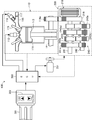
- FIG. 1 is a block diagram schematically illustrating an overall configuration of a vehicle power transmission system according to the present invention. It is sectional drawing which shows typically the outline of the specific structure of the principal part of the power transmission device shown in FIG.
- FIG. 3 is a partially enlarged cross-sectional view showing an enlarged configuration inside a broken-line circle A shown in FIG. 2.
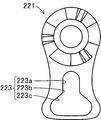
- FIG. 3 is a partially broken front view schematically showing an internal configuration before a downshift operation when the power transmission device shown in FIG. 2 is viewed from the right side in the figure. It is a front view which shows roughly the external appearance structure of the movable clutch lifter shown in FIG.
- FIG. 5 is a partially broken plan view schematically showing an internal state of one process during a downshift operation in the power transmission device shown in FIG. 4.
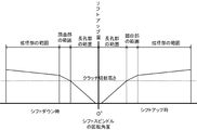
- FIG. 2 is an explanatory diagram showing a relationship between a rotation angle of a shift spindle and a lift-up amount at the time of shift down of a gear stage of the vehicle power transmission system shown in FIG. 1.
- FIG. 1 is a block diagram schematically showing an outline of the overall configuration of a vehicle power transmission system 100 according to the present invention. Note that each drawing referred to in the present specification is schematically represented by exaggerating some of the components in order to facilitate understanding of the present invention. For this reason, the dimension, ratio, etc. between each component may differ.
- the vehicle power transmission system 100 is a group of mechanical devices that transmit to a driving wheel a rotational driving force generated by an engine that is a prime mover in a two-wheeled vehicle (so-called motorcycle). And below the fuel tank).
- the vehicle power transmission system 100 includes an engine 110.
- the engine 110 is a prime mover that is mounted on a vehicle (not shown) and generates a rotational driving force by burning fuel. Specifically, the engine 110 introduces an air-fuel mixture composed of fuel and air into a cylindrical cylinder 111 and ignites the air-fuel mixture with an ignition plug 112 to explode the piston 113.
- This is a so-called reciprocating engine that reciprocates in a cylinder 111 and generates a rotational driving force on a crankshaft 114 connected to a piston 113.
- the engine 110 is assumed to be a so-called four-stroke engine.
- An intake pipe 116 is connected to a cylinder 111 constituting a combustion chamber in the engine 110 via an intake valve 115.
- the intake pipe 116 is a pipe for supplying an air-fuel mixture into the cylinder 111, and supplies (injects) fuel in the form of a mist into the throttle valve 117 and the cylinder 111 for adjusting the amount of air supplied into the cylinder 111.
- Each injector 118 is provided. Among these, the operation of the spark plug 112 and the injector 118 is controlled by an ECU 300 described later, and the throttle valve 117 is operated by a manual operation by a vehicle operator.
- the power transmission device 200 is connected to the crankshaft 114 in the engine 110 via a primary drive gear 114a.
- the power transmission device 200 is a mechanical device that transmits the rotational driving force generated by the engine 110 at a plurality of shift speeds, and mainly includes a clutch 210 and a transmission 240.
- the clutch 210 is disposed between the engine 110 and the transmission 240 on the transmission path of the rotational driving force generated by the engine 110, and transmits and blocks the rotational driving force generated by the engine 110 to the transmission 240. It is a mechanical device. Specifically, as shown in FIGS. 2 to 6, the clutch 210 is provided on one end side (the right side in the drawing) of the main shaft 241 extending in the shape of a shaft from the transmission 240. A plurality of friction plates 211 and clutch plates 212 formed in the above are alternately accommodated in the clutch case 201 in a state where a plurality of the friction plates 211 and the clutch plates 212 are alternately arranged. That is, the clutch 210 in the present embodiment is a so-called multi-plate clutch.
- Each of the plurality of friction plates 211 is composed of a ring body whose outer peripheral portion is radially formed in a concavo-convex shape, and a plurality of small pieces of friction material 211a are attached to both surfaces of the plate surfaces of these ring bodies. Configured.
- one through-hole 211b having an inner diameter larger than the other friction plates 211 is formed in one friction plate 211 located in the center of the figure sandwiched between two clutch plates 212.
- the driving force transmission plate 213 is disposed inside the through hole 211b.
- the plurality of friction plates 211 are held in a state of being fitted into the clutch shell 214, respectively.
- each of the plurality of clutch plates 212 is configured by a ring body in which inner peripheral portions are radially formed in an uneven shape.
- the plurality of clutch plates 212 are held in a state of being fitted into the clutch hub 215, respectively.
- the driving force transmission plate 213 is disposed between the two clutch plates 212 and is a ring for pressing the two clutch plates 212 toward the friction plates 211 disposed outside the two clutch plates 212, respectively. It is made of a steel plate wave spring (also called “wave washer”).
- the driving force transmission plate 213 is wider than the separation distance between the two clutch plates 212 adjacent to each other in a disconnected state in which a pressing force from pressure plates 219a and 219b, which will be described later, is eliminated and the clutch 210 does not transmit the driving force. It is composed of various wave widths.
- the driving force transmission plate 213 always exerts a pressing force toward the outside with respect to the two clutch plates 212 located on both sides of the driving force transmission plate 213 in a state where the driving force transmission plate 213 is fitted on the outer peripheral surface of the clutch hub 215. Has been granted.
- the clutch shell 214 is integrally fixed to a primary driven gear 216 that meshes with the primary drive gear 114 a while holding the friction plate 211, and rotates together with the primary drive gear 114 a, that is, the crankshaft 114.
- the clutch hub 215 is integrally connected to the main shaft 241 while holding the clutch plate 212 and the driving force transmission plate 213, and integrally with the main shaft 241, the clutch plate 212, and the driving force transmission plate 213. Rotating drive.
- the clutch hub 215 is formed with an overhanging portion 215a that protrudes along the clutch plate 212. Inside the overhanging portion 215a, the friction plate 211 and the clutch plate 212 are alternately arranged. A resistance applying body 217 is provided in a state of facing the outermost clutch plate 212.
- the resistance force imparting body 217 is a component for imparting a resistance force against the pressing force applied by the pressure plates 219a and 219b to the friction plate 211 and the clutch plate 212, and is weaker than the elastic force of the clutch spring 218. It is comprised by the disc spring which generate
- a pair of the friction plates 211 and the clutch plates 212 that are alternately arranged on each other are pressed and brought into close contact with the elastic force of the clutch spring 218 made of a disc spring with the friction plate 211 and the clutch plate 212 sandwiched therebetween.
- Pressure plates 219a and 219b are provided.
- the fixed clutch lifter 220 is disposed opposite to the outer side (right side of the drawing) of the pressure plate 219b on the right side of the drawing via the movable clutch lifter 221.
- the fixed clutch lifter 220 is a mechanism that generates a pressing force that presses the pressure plate 219b in a direction against the elastic force of the clutch spring 218 in cooperation with the movable clutch lifter 221.
- the fixed clutch lifter 220 has an inclined surface that faces the movable clutch lifter 221, and a plurality of steel balls 220 a are formed by the inclined surface and the inclined surface formed on the movable clutch lifter 221. Holding.
- the movable clutch lifter 221 is a bar member that constitutes a part of the fixed clutch lifter 220 and that rotates a portion that holds a steel ball 220a by rotational driving of a shift spindle 230 described later.
- the friction plate 211 and the clutch plate 212 are brought into close contact with each other, whereby the clutch shell 214 and the clutch hub 215 are integrally rotated to transmit the rotational driving force of the engine 110 to the transmission 240.
- the clutch 210 transmits the transmission by eliminating the contact state between the friction plate 211 and the clutch plate 212 by the fixed clutch lifter 220 pressing the pressure plate 219b via the movable clutch lifter 221 to weaken the elastic force of the clutch spring 218.
- the rotational driving force of the engine 110 with respect to 240 is shut off.
- the shift spindle 230 is connected to the fixed clutch lifter 220 in the clutch 210 via a movable clutch lifter 221 and a clutch lifter lever 222 as shown in FIGS.
- the clutch lifter lever 222 is a bar member that connects the movable clutch lifter 221 and the shift spindle 230.
- One end of the clutch lifter lever 221 is connected to the movable clutch lifter 221 and the other end is integrally fixed to the shift spindle 230. Has been.
- movable clutch lifter 221 and clutch lifter lever 222 are connected in a loose manner. More specifically, a lift amount defining hole 223 including a through hole is formed at the end of the movable clutch lifter 221, and the lift amount defining hole 223 is provided in a state protruding from the end of the clutch lifter lever 222.
- the boss 224 is movably fitted.
- the lift amount defining hole 223 is formed with a long hole portion 223 having a diameter slightly larger than the outer shape of the boss 224 toward the shaft side of the clutch 210, and an end portion of the long hole portion 223 is directed outward.
- a diameter-enlarged portion 223c having an enlarged hole diameter via a bent portion 223b is provided.
- the shift spindle 230 is a shaft body that is driven to rotate in the corresponding rotation direction based on an operation control related to a shift-up or shift-down gear shifting operation performed by the ECU 300, which will be described later.
- the other end is connected to the shift spindle drive motor 231 while being connected to the lifter 221.
- the shift spindle drive motor 231 is an electric motor that is rotationally driven by operation control by the ECU 300. That is, the vehicle power transmission system 100 drives the clutch 210 and the transmission 240 by an actuator composed of one shift spindle drive motor 231.
- the transmission 240 is a mechanical device for shifting the rotational driving force generated from the engine 110 at a plurality of shift speeds (for example, four speed shifts) and transmitting it to the drive wheels.
- a main shaft 241 connected to the crankshaft 114 of the engine 110 via a clutch 210 and a counter shaft 242 (not shown in FIG. 2) connected to driving wheels are arranged in parallel to each other.
- a plurality of gear trains that constitute a plurality of gear stages having different gear ratios are provided.
- a plurality of gear trains provided between the main shaft 241 and the counter shaft 242 are a plurality of driving gears 241 a provided on the main shaft 241 and a plurality of driven gears 242 a provided on the counter shaft 242. These drive-side gear 241a and driven-side gear 242a are always meshed with each other in pairs.
- One drive side gear 241a or driven side gear 242a constituting this pair is fixedly supported with respect to the main shaft 241 or counter shaft 242, and the other driven side gear 242a constituting the same pair or
- the main shaft 241 is supported so as to be slidable in the axial direction with respect to the counter shaft 242 or the main shaft 241.
- the drive side gear 241a and the driven side gear 242a are a convex dog tooth 243a and a concave dog tooth that are fitted to each other between the adjacent drive side gear 241a and the driven side gear 242a constituting one shift stage.
- 243b is formed on the side surfaces facing each other.
- the drive side gears 241a and the driven side gears 242a adjacent to each other constituting one shift stage are connected to and separated from each other on the main shaft 241 and the counter shaft 242. That is, the drive side gears 241a and the driven side gears 242a adjacent to each other on the main shaft 241 and the counter shaft 242 are configured to be connected and separated by a dog clutch method.
- a shift fork 244 is provided on the outer side of the drive side gears 241a and the driven side gears 242a that are connected and separated from each other.
- the shift fork 244 is a component that presses and slides the drive side gear 241a and the driven side gear 242a that are slidable in the axial direction, and includes a bifurcated plate-like body surrounding the drive side gear 241a and the driven side gear 242a.
- the shift fork 244 is formed of a cylindrical body, and a groove 245a is formed on the outer peripheral surface of the cylindrical body.
- the shift fork 244 is supported by a shift drum 245 positioned at a rotational position corresponding to the gear position of the transmission 240.
- a part of the shift fork 244 is fitted in a groove 245 a formed on the outer peripheral surface of the shift drum 245, and the outer peripheral surface of the shift drum 245 follows the groove 245 a by rotational driving of the shift drum 245. Slide displacement along the axial direction on the top.
- an index plate 246b formed in a star shape having five shift drum pins 246a and five protrusions is provided.
- the rotational displacement of the shift drum 245 is elastically restricted by pressing the tip of the index arm 247 against the valley of the index plate 246b by the index spring 247a.
- a shift spindle 230 is connected to the shift drum pin 246 a of the shift drum 245 via a gear shift arm 248 and a gear shift arm drive lever 249.
- the gear shift arm 248 is a bar member that is rotatably supported by the shift spindle 230 with a hook 248a hooked to the shift drum pin 246a so as to be able to rotate and slide.
- the hook 248a is configured to have two hook-shaped portions on both sides of the shift drum pin 246a in order to rotate the shift drum pin 246a in the rotation direction corresponding to each shift operation of the transmission 240 upshifting and downshifting. Yes.
- the gear shift arm drive lever 249 is a bar member that connects the gear shift arm 248 and the shift spindle 230, one end of which is freely connected to the gear shift arm 248 and the other end to the shift spindle 230. It is fixed integrally.
- the gear shift arm 248 and the gear shift arm drive lever 249 are positioned at a neutral position by a gear shift return spring 250 supported by the shift spindle 230.
- the ECU 300 (Engine Control Unit) is configured by a microcomputer including a CPU, a ROM, a RAM, and the like, and comprehensively controls the entire operation of the vehicle power transmission system 100 according to a control program (not shown) stored in advance in the ROM. Control.
- the ECU 300 provides information necessary for controlling the operation of the vehicle power transmission system 100 to the engine 110 and the power transmission device 200 (for example, the rotational speed of the engine 110, the vehicle speed, the opening of the throttle valve 117, the amount of oxygen in the exhaust pipe, the shift).
- Various sensors (not shown) for obtaining the rotation angle of the spindle 230, the shift position, the clutch lift amount, etc.) are provided.
- the ECU 300 when the ECU 300 is set to a drive mode in which the vehicle is driven based on a control signal from a drive switch 302 provided on the handle 301 of the vehicle, the ECU 300 and the power transmission based on the information acquired from the various sensors.
- the operation of the apparatus 200 more specifically, the operation of the spark plug 112, the injector 118, and the shift spindle drive motor 231 is controlled to control the combustion of the engine 110, the connection and disconnection of the clutch 210, and the upshift and Each shift-down operation is performed.
- the ECU 300 comprehensively controls the operation of not only the vehicle power transmission system 100 but also the entire vehicle on which the vehicle power transmission system 100 is mounted. Moreover, in FIG. 1, the path
- the vehicle power transmission system 100 is disposed below the seating seat and the fuel tank in the two-wheeled motor vehicle, and when the ECU 300 is set to the drive mode, that is, the vehicle is traveling or is capable of traveling.
- the up-shift control or the down-shift control corresponding to the vehicle speed is automatically performed by the operation control of the ECU 300.
- the shift-up operation and the shift-down operation in the vehicle power transmission system 100 by the shift-up control and the shift-down control by the ECU 300 are the same except for the rotation direction of the shift spindle 230 and the operation caused by the rotation direction. Therefore, in the following description of the operation, the shift-down operation of the transmission 240 when the vehicle is likely to hit the dog will be described, but the shift-up operation is the same.
- the ECU 300 changes the gear speed according to the vehicle speed. Is lowered stepwise and the transmission 240 is shifted down to one gear position while the vehicle speed is “0 km / h” and the clutch 210 is disengaged. However, when the vehicle is suddenly stopped, the vehicle may stop before the shift stage is shifted down to one stage, that is, at any one of the second to fourth shift stages.
- the ECU 300 controls the operation of the power transmission device 200 to disengage the clutch 210. Specifically, the ECU 300 operates the shift spindle drive motor 231 to rotate the shift spindle 230 (see the broken line arrow in the figure), thereby rotating the clutch lifter lever 222 to the left side in the figure. Accordingly, the movable clutch lifter 221 rotates at a rotation angle corresponding to the positions of the long hole portion 223a, the bent portion 223b, and the enlarged diameter portion 223c of the lift amount defining hole 223 in which the boss 224 of the clutch lifter lever 222 slides. To do.
- the relationship between the rotation angle of the shift spindle 230 and the distance between the pressure plates 219a and 219b is shown in FIG. 7, where the boss 224 of the clutch lifter lever 222 defines the lift amount.
- the boss 224 of the clutch lifter lever 222 defines the lift amount.
- the length of the long hole portion 223a on which the boss 224 slides is set to a length that is a lift-up amount at which the friction plate 211 and the clutch plate 212 are separated from each other so that the driving force is not transmitted. .
- the lift-up increases slightly with respect to the start of rotation of the shift spindle 230, which is the so-called play between the lift amount defining hole 223 and the boss 224 and the fixed clutch lifter 220. This is because so-called play between the steel ball 220a and the movable clutch lifter 221 is set.
- the ECU 300 rotates the shift spindle 230 to the vicinity of the bent portion 223b of the lift amount defining hole 223 in the movable clutch lifter 221 or more.
- the clutch 210 is in a disconnected state in which the friction plate 211 and the clutch plate 212 are separated from each other and the driving force from the engine 110 is hardly transmitted to the transmission 240.
- the clutch 210 includes a driving force transmission plate 213 between the two clutch plates 212.
- the two clutch plates 212 located on both sides of the driving force transmission plate 213 are outside (pressure plate 219a) by the elastic force of the driving force transmission plate 213 even when the friction plate 211 and the clutch plate 212 are separated from each other. , 219b side) and contact or approach each friction plate 211 arranged adjacent to the outside of the two clutch plates 212.
- the clutch 210 transmits a very small driving force when the vehicle is stopped, even in a disconnected state where the pressure plates 219a and 219b are completely lifted up. That is, in the power transmission device 200, the driving force from the engine 110 is slightly transmitted to the transmission 240 even when the vehicle is stopped.
- the ECU 300 continuously controls the operation of the transmission 240 so that the gear position in the transmission 240 is shifted down to the first speed after the clutch 210 is disengaged. Specifically, the ECU 300 controls the operation of the shift spindle drive motor 231 to further rotate the shift spindle 230 to increase the diameter of the boss 224 of the clutch lifter lever 222 in the lift amount defining hole 223 of the movable clutch lifter 221. Displace to part 223c.
- the transmission 240 causes the gear shift arm 248 to hook the shift drum pin 246a and rotate the shift drum 245, thereby sliding the shift fork 244 to recombine the drive side gear 241a and the driven side gear 242a, that is, The gear position is changed.
- This speed change process includes a gear pulling process in which the convex dog teeth 243a in the driving gears 241a and the driven gears 242a that are engaged with each other are pulled out from the concave dog teeth 243b, and a drive that is separated from each other.
- This includes a step of connecting gears in which the convex dog teeth 243a in the side gears 241a and the driven gears 242a are fitted into the concave dog teeth 243b.
- the driving side gear 241a and the driven side gear 242a are slightly rotated continuously or intermittently by a slight driving force transmitted from the clutch 210.
- the driving side gear 241a and the driven side gear 242a in the transmission 240 have the driving side gear 241a and the driven side gear 242a even when the dog contact where the convex dog teeth 243a and the concave dog teeth 243b collide occurs.
- the drive side gears 241a and the driven side gears 242a can be connected to each other while suppressing the occurrence of the dog hitting.
- the ECU 300 further reverses the shift spindle 230 via the shift spindle drive motor 231 within the range where the boss 224 is located in the enlarged diameter portion 223c, that is, the range where the clutch 210 is in the disconnected state, and then further bends 223b.
- the transmission 240 can continuously shift down the gear position by causing the gear shift arm 248 to hook the next shift drum pin 246a and rotate the shift drum 245. Therefore, ECU 300 can continuously shift down the gear position in transmission 240 even when the vehicle is stopped.
- the ECU 300 can also shift the shift speed from the first speed to the neutral speed by controlling the operation of the shift spindle drive motor 231 in the same manner as described above.
- the ECU 300 controls the operation of the shift spindle drive motor 231 to return the shift spindle 230 to the neutral position.
- the clutch 210 cancels the pressing force from the fixed clutch lifter 220 against the pressure plates 219a and 219b, so that the friction plate 211 and the clutch plate 212 are brought into close contact with each other by the pressing force of the pressure plates 219a and 219b. Start transmitting.
- the clutch 210 includes a resistance applying body 217 that applies a resistance force against the pressing force applied by the pressure plates 219a and 219b to the friction plate 211 and the clutch plate 212.
- the clutch 210 can bring the friction plate 211 and the clutch plate 212 into gentle contact with each other, thereby making it possible to suppress sudden oscillation or engine stall of the vehicle.
- the ECU 300 controls the operation of the shift spindle drive motor 231 and rotationally displaces the shift spindle 230 to the left in the figure, thereby shifting up the gear position in the transmission 240 according to the vehicle speed by the same operation as that during the downshift. can do.
- the vehicle driving force transmission system 100 is more than the thickness of the friction plates 211 disposed between the clutch plates 212 and between the clutch plates 212 adjacent to each other.
- a wide driving force transmission plate 213 is provided.
- one driving force transmission plate 213 is provided between the two clutch plates 212.
- the driving force transmission plate 213 is not limited as long as the friction plate 211 and the clutch plate 212 can be brought close to each other so that a part of the friction plate 211 and the clutch plate 212 are brought into contact with each other or generate drag torque.
- the present invention is not limited to the above embodiment. Therefore, the driving force transmission plate 213 may be configured to be disposed between the friction plates 211 instead of or in addition to the clutch plates 212, for example. Further, the driving force transmission plate 213 may be provided at two or more places, and the number of arrangement at one place may be two or more.
- the driving force transmission plate 213 is configured with a wave width wider than the separation distance between the two clutch plates 212 adjacent to each other.
- the driving force transmission plate 213 is wider than the thickness of the friction plate 211 (or clutch plate 212) disposed between the two clutch plates 212 (or between the friction plates 211) where the driving force transmission plate 213 is disposed. It only has to be formed.
- the driving force transmission plate 213 is constituted by a wave spring that can be elastically deformed in the separation width direction of the clutch plate 212.
- the driving force transmission plate 213 is thicker than the thickness of the friction plate 211 (or clutch plate 212) disposed between the two clutch plates 212 (or between the friction plates 211) where the driving force transmission plate 213 is disposed. It may be a simple ring-shaped plate formed at the same time.
- the resistance imparting body 217 is provided inside the pressure plate 219b of the clutch 210.
- the resistance imparting body 217 is for suppressing the friction plate 211 and the clutch plate 212 from abruptly contacting each other. Therefore, even if the clutch 210 is configured by omitting the resistance force imparting body 217, the clutch 210 can exert the effect of the driving force transmission plate 213.
- the vehicle power transmission system 100 is configured by directly coupling the clutch 210 to the crankshaft 114 of the engine 110 without using a centrifugal clutch or the like. As a result, the vehicle power transmission system 100 can transmit the driving force without causing an engine stall even when the clutch 210 is disengaged while the vehicle is stopped. Can be reconnected to. However, the vehicle power transmission system 100 can also be configured by indirectly coupling the clutch 210 and the engine 110 via a centrifugal clutch or the like.
- Vehicle power transmission system DESCRIPTION OF SYMBOLS 110 ... Engine, 111 ... Cylinder, 112 ... Spark plug, 113 ... Piston, 114 ... Crankshaft, 114a ... Primary drive gear, 115 ... Intake valve, 116 ... Intake pipe, 117 ... Throttle valve, 118 ... Injector, 200 ... power transmission device, 201 ... clutch case, 210 ... Clutch, 211 ... Friction plate, 211a ... Friction material, 211b ... Through hole, 212 ... Clutch plate, 213 ... Driving force transmission plate, 214 ... Clutch shell, 215 ... Clutch hub, 216 ...
- concave side dog, 244 ... shift fork, 245 ... shift drum, 245a ... Groove, 246a ... shift drum pin, 246b ... index plate, 247 ... index arm, 247a ... index spring, 248 ... gear shift arm, 248a ... hook, 249 ... gear shift arm drive lever, 250 ... gear shift return spring, 300 ... ECU, 301 ... handle, 302 ... drive switch.
Landscapes
- Engineering & Computer Science (AREA)
- General Engineering & Computer Science (AREA)
- Mechanical Engineering (AREA)
- Mechanical Operated Clutches (AREA)
Abstract
トランスミッションの変速動作時におけるドッグ当たりを迅速に解消して変速動作を早期に完了することができるクラッチおよび同クラッチを備えた車両用動力伝達システムを提供する。 車両用動力伝達システム100は、ECU300によって作動が制御されるエンジン110、クラッチ210およびトランスミッション240を備えている。クラッチ210は、エンジン110の駆動力によって回転する複数のフリクションプレート211と車両の駆動輪側に連結される複数のクラッチプレート212とを交互に配置した状態で保持している。2つのクラッチプレート212の間には、ウェーブスプリングからなる駆動力伝達プレート213が設けられている。駆動力伝達プレート213は、2つのクラッチプレート212の離隔距離よりも幅広なウェーブ幅で構成されており、2つのクラッチプレート212に対して常に外側に向かって押圧力を付与している。
Description
本発明は、互いに交互に配置されたフリクションプレートとクラッチプレートとが密着または離隔することによってエンジンの駆動力を伝達または遮断するクラッチ、およびこのクラッチを備えた車両用動力伝達システムに関する。
従来から、自動二輪車や四輪バギー車などの自走式車両においては、エンジン(原動機)で発生した駆動力を駆動輪に伝達するために動力伝達装置が設けられている。動力伝達装置は、エンジンのクランクシャフトに対して接続および切断しながら同クランクシャフトの回転数を変速しつつ駆動輪に伝達する機械装置であり、主としてクラッチとトランスミッションによって構成されている。ここで、クラッチとは、エンジンの回転駆動軸に対して接続および切断しながら同クランクシャフトの回転駆動力をトランスミッション側に伝達する機械装置である。
また、トランスミッションとは、エンジンのクランクシャフトの回転数を複数のギアの組合せによって構成される複数の変速段で変速させて駆動輪側に伝達する機械装置である。この場合、トランスミッションの変速段は、例えば、下記特許文献1に示すように、エンジンの駆動力によって回転駆動するメインシャフトおよび車両の駆動輪に連結されるカウンターシャフトに対してそれぞれドッグクラッチ方式で固定または固定解除可能に設けられた複数の駆動側ギアと複数の従動側ギアとを互いに噛合わせる組合せによって構成される。
ここで、ドッグクラッチ方式(「ドグクラッチ方式」ともいう)とは、メインンシャフトおよびカウンターシャフト上をそれぞれ空転する駆動側空転ギアおよび従動側空転ギアと、メインンシャフトおよびカウンターシャフトとそれぞれ一体回転する駆動側一体回転体および従動側一体回転体とを駆動側空転ギアおよび従動側空転ギア、および駆動側一体回転体および従動側一体回転体にそれぞれ設けた互いに噛合う一対の凸側ドッグと凹側ドッグとからなるドッグ歯を介して連結または連結解除する連結手法である。なお、駆動側一体回転体および従動側一体回転体は、それぞれギアや単なる円板体で構成される。
しかしながら、上記特許文献1に記載された動力伝達装置においては、変速動作時に互いに隣り合うドッグ歯同士が衝突して適切に噛み合わない所謂ドッグ当たりが生じた場合、一旦クラッチを接続してドッグ歯同士の回転方向の位置を変更して再度変速動作を実行するように構成されているため、変速動作に時間が掛かることがあるという問題があった。
本発明は上記問題に対処するためなされたもので、その目的は、トランスミッションの変速動作時におけるドッグ当たりを迅速に解消して変速動作を早期に完了することができるクラッチおよび同クラッチを備えた車両用動力伝達システムを提供することにある。
上記目的を達成するため、請求項1に係る本発明の特徴は、エンジンから伝達される駆動力によって回転駆動する複数のフリクションプレートと、フリクションプレートに対して交互に配置されるとともに互いに隣接するフリクションプレートに対して密着または離隔することより駆動力を伝達または遮断する複数のクラッチプレートとを備えたクラッチにおいて、フリクションプレート間および/またはクラッチプレート間に、互いに隣接するフリクションプレート間および/またはクラッチプレート間に配置されたクラッチプレートおよび/またはフリクションプレートの各厚さよりも幅広の駆動力伝達プレートを備えたことにある。
このように構成した本発明の特徴によれば、クラッチは、フリクションプレート間およびクラッチプレート間の少なくとも一方に、互いに隣接するフリクションプレート間および/またはクラッチプレート間に配置されたクラッチプレートおよび/またはフリクションプレートの各厚さよりも幅広の駆動力伝達プレートを備えている。これにより、クラッチは、クラッチの切断状態においても駆動力伝達プレートの両側に位置するクラッチプレートおよび/またはフリクションプレートがこれらの外側に位置するフリクションプレートおよび/またはクラッチプレートに接触または接触に近い状態となって僅かな駆動力を伝達する状態となる。このため、本発明に係るクラッチに連結されるトランスミッションにおいては、クラッチの切断時においても僅かな駆動力が伝達されて駆動側ギアが連続的または断続的に回転駆動するため、変速動作時におけるドッグ当たりを迅速に解消して変速動作を早期に完了することができる。
また、本発明の他の特徴は、前記クラッチにおいて、駆動力伝達プレートは、フリクションプレート間の離隔幅および/またはクラッチプレート間の離隔幅よりも幅広に形成されていることにある。
このように構成した本発明の他の特徴によれば、クラッチは、駆動力伝達プレートがフリクションプレート間の離隔幅および/またはクラッチプレート間の離隔幅よりも幅広に形成されているため、駆動力伝達プレートの両側のクラッチプレートおよび/またはフリクションプレートがこれらの外側に位置するフリクションプレートおよび/またはクラッチプレートにより接触または接触に近い状態となってより確実に駆動力を伝達することができる。
また、本発明の他の特徴は、前記クラッチにおいて、駆動力伝達プレートは、フリクションプレート間の離隔幅方向および/またはクラッチプレート間の離隔幅方向に弾性変形可能に形成されていることにある。この場合、駆動力伝達プレートは、ウェーブスプリング(「ウェーブワッシャ」ともいう)で構成するとよい。
このように構成した本発明の他の特徴によれば、クラッチは、駆動力伝達プレートがフリクションプレート間の離隔幅方向および/またはクラッチプレート間の離隔幅方向に弾性変形可能に形成されているため、クラッチの接続状態において駆動力伝達プレートが圧縮する方向に弾性変形することができる。これにより、クラッチは、接続状態において駆動力伝達プレートの両側のクラッチプレートおよび/またはフリクションプレートがこれらのクラッチプレート間および/またはフリクションプレート間に位置するフリクションプレートおよび/またはクラッチプレートに対して密着して駆動力を確実に伝達することができる。
また、本発明の他の特徴は、前記クラッチにおいて、さらに、互いに交互に配置されたフリクションプレートとクラッチプレートとを互いに密着させるための押圧力をフリクションプレートおよびクラッチプレートに対して付与するプレッシャプレートと、プレッシャプレートの押圧力に抗する抵抗力をフリクションプレートおよびクラッチプレートに対して付与する抵抗力付与体とを備えていることにある。この場合、抵抗力付与体は、互いに交互に配置されたフリクションプレートとクラッチプレートとからなるプレート群の最も外側位置に配置するとよい。
このように構成した本発明の他の特徴によれば、クラッチは、互いに交互に配置されたフリクションプレートとクラッチプレートに対してプレッシャプレートの押圧力に抗する抵抗力を付与する抵抗力付与体を備えているため、プレッシャプレートの押圧力によってフリクションプレートとクラッチプレートとが急激に密着することを防止することができ、車両の急な変速(急発進、急加速および急減速)を防止することができる。
また、本発明はクラッチの発明として実施できるばかりでなく、このクラッチを備えた車両用動力伝達システムの発明としても実施できるものある。
具体的には、車両用動力伝達システムは、車両に搭載されて燃料の燃焼によって駆動力を発生させるエンジンと、エンジンによる駆動力によって回転駆動するメインシャフトおよび車両の駆動輪に連結されるカウンターシャフトにそれぞれ設けられた複数の駆動側ギアおよび複数の従動側ギアがそれぞれドッグクラッチ方式で互いに連結または連結解除されるとともに複数の駆動側ギアと複数の従動側ギアとを互いに噛合わせる組合せによって互いに変速比の異なる複数の変速段を構成してエンジンの回転速度を変速しつつ駆動力を駆動輪に伝達するトランスミッションと、エンジンから伝達される駆動力によって回転駆動する複数のフリクションプレートと同複数のフリクションプレートに対して交互に配置された複数のクラッチプレートとを互いに密着または離隔させることよってエンジンの駆動力をトランスミッションに伝達または遮断するクラッチとを備えた車両用動力伝達システムにおいて、クラッチは、フリクションプレート間および/またはクラッチプレート間に、互いに隣接するフリクションプレート間および/またはクラッチプレート間に配置されたクラッチプレートおよび/またはフリクションプレートの各厚さよりも幅広の駆動力伝達プレートを備えるようにするとよい。このように構成した駆動力伝達プレートは、前記クラッチと同様の作用効果を期待することができる。
以下、本発明に係る車両用動力伝達システムの一実施形態について図面を参照しながら説明する。図1は、本発明に係る車両用動力伝達システム100の全体構成の概略を模式的に示すブロック図である。なお、本明細書において参照する各図は、本発明の理解を容易にするために一部の構成要素を誇張して表わすなど模式的に表している。このため、各構成要素間の寸法や比率などは異なっていることがある。この車両用動力伝達システム100は、二輪自動車(所謂オートバイ)において原動機であるエンジンで発生させた回転駆動力を駆動輪に伝達する機械装置群であり、二輪自動車におけるエンジンの周辺(例えば、着座シートや燃料タンクの下方)に設けられる。
(車両用動力伝達システム100の構成)
車両用動力伝達システム100は、エンジン110を備えている。エンジン110は、図示しない車両に搭載されて燃料の燃焼によって回転駆動力を発生させる原動機である。具体的には、エンジン110は、筒状に形成されたシリンダ111内に燃料と空気とからなる混合気を導入するとともに、この混合気を点火プラグ112によって点火して爆発させることによりピストン113をシリンダ111内で往復運動させてピストン113に連結されるクランクシャフト114に回転駆動力を発生させる所謂レシプロエンジンである。本実施形態においては、エンジン110は、所謂4ストロークエンジンを想定しているが、所謂2ストロークエンジンであってもよいことは当然である。
車両用動力伝達システム100は、エンジン110を備えている。エンジン110は、図示しない車両に搭載されて燃料の燃焼によって回転駆動力を発生させる原動機である。具体的には、エンジン110は、筒状に形成されたシリンダ111内に燃料と空気とからなる混合気を導入するとともに、この混合気を点火プラグ112によって点火して爆発させることによりピストン113をシリンダ111内で往復運動させてピストン113に連結されるクランクシャフト114に回転駆動力を発生させる所謂レシプロエンジンである。本実施形態においては、エンジン110は、所謂4ストロークエンジンを想定しているが、所謂2ストロークエンジンであってもよいことは当然である。
このエンジン110における燃焼室を構成するシリンダ111には、吸気バルブ115を介して吸気管116が接続されている。吸気管116は、シリンダ111内に混合気を供給するための配管であり、シリンダ111内に供給する空気量を調整するスロットルバルブ117および同シリンダ111内に燃料を霧状にして供給(噴射)するインジェクタ118をそれぞれ備えている。これらのうち、点火プラグ112およびインジェクタ118は後述するECU300によって作動がそれぞれ制御されるとともに、スロットルバルブ117は車両の操縦者による手動操作によって作動する。
エンジン110におけるクランクシャフト114には、プライマリードライブギア114aを介して動力伝達装置200が連結されている。動力伝達装置200は、エンジン110により発生された回転駆動力を複数の変速段で変速して伝達する機械装置であり、主として、クラッチ210およびトランスミッション240によって構成されている。
クラッチ210は、エンジン110で発生させた回転駆動力の伝達経路上におけるエンジン110とトランスミッション240との間に配置されてエンジン110が発生させた回転駆動力をトランスミッション240に対して伝達および遮断を行なう機械装置である。このクラッチ210は、詳しくは、図2~図6に示すように、トランスミッション240から軸状に延びるメインシャフト241の一方(図示右側)の端部側に設けられており、鋼板材をそれぞれリング状に形成したフリクションプレート211とクラッチプレート212とが交互に複数枚ずつ配置された状態でクラッチケース201内に回転可能な状態でそれぞれ収容されて構成されている。すなわち、本実施形態におけるクラッチ210は、所謂多板クラッチで構成されている。
複数のフリクションプレート211は、それぞれ外周部が放射状に凹凸形状に形成されたリング体で構成されており、これらのリング体の板面の両面に小片状の摩擦材211aが複数枚貼り付けられて構成されている。これらの複数のフリクションプレート211のうち、2つのクラッチプレート212で挟まれた図示中央に位置する1つのフリクションプレート211には、内径が他のフリクションプレート211よりも大きく形成された貫通孔211bが形成されており、この貫通孔211bの内側に駆動力伝達プレート213が配置されている。そして、これらの複数のフリクションプレート211は、クラッチシェル214にそれぞれ嵌め込まれた状態で保持されている。
一方、複数のクラッチプレート212は、それぞれ内周部が放射状に凹凸形状に形成されたリング体で構成されている。これらの複数のクラッチプレート212は、クラッチハブ215にそれぞれ嵌め込まれた状態で保持されている。
駆動力伝達プレート213は、2つのクラッチプレート212の間に配置されてこれら2つクラッチプレート212をそれぞれこれら2つのクラッチプレート212の外側に配置された各フリクションプレート211に向かって押圧するためのリング状の部品であり、鋼板製のウェーブスプリング(「ウェーブワッシャ」ともいう)で構成されている。この駆動力伝達プレート213は、後述するプレッシャプレート219a,219bからの押圧力が解消されてクラッチ210が駆動力を伝達しない切断状態において互いに隣接し合う前記2つのクラッチプレート212の離隔距離よりも幅広なウェーブ幅で構成されている。これにより、駆動力伝達プレート213は、クラッチハブ215の外周面上に嵌合した状態で駆動力伝達プレート213の両側に位置する前記2つのクラッチプレート212に対して常に外側に向かって押圧力を付与している。
クラッチシェル214は、フリクションプレート211を保持しつつ前記プライマリードライブギア114aに噛み合うプライマリードリブンギア216に一体的に固定されてプライマリードライブギア114a、すなわち、クランクシャフト114とともに一体的に回転駆動する。また、クラッチハブ215は、クラッチプレート212および駆動力伝達プレート213をそれぞれ保持しつつメインシャフト241に一体的に連結されており、メインシャフト241、クラッチプレート212および駆動力伝達プレート213とともに一体的に回転駆動する。
このクラッチハブ215には、クラッチプレート212に沿って張り出した張出部215aが形成されており、この張出部215aの内側には互いに交互に配置されたフリクションプレート211およびクラッチプレート212のうちの最も外側に配置されたクラッチプレート212に対向した状態で抵抗力付与体217が設けられている。
抵抗力付与体217は、フリクションプレート211およびクラッチプレート212に対してプレッシャプレート219a,219bが付与する押圧力に抗する抵抗力を付与するための部品であり、クラッチスプリング218の弾性力よりも弱い弾性力を発生させる皿バネによって構成されている。
また、互いに交互に配置されたフリクションプレート211およびクラッチプレート212の外側には、皿バネからなるクラッチスプリング218の弾性力によってフリクションプレート211とクラッチプレート212とを挟んだ状態で押圧して密着させる一対のプレッシャプレート219a,219bがそれぞれ設けられている。これらのうち、図示右側のプレッシャプレート219bの外側(図示右側)には、可動クラッチリフター221を介して固定クラッチリフター220が対向配置されている。
固定クラッチリフター220は、可動クラッチリフター221と協働してプレッシャプレート219bをクラッチスプリング218の弾性力に抗する方向に押圧する押圧力を発生させる機構である。具体的には、固定クラッチリフター220は、可動クラッチリフター221と対向する対向面が傾斜面で構成されており、この傾斜面と可動クラッチリフター221に形成された傾斜面とで複数の鋼球220aを保持している。可動クラッチリフター221は、固定クラッチリフター220の一部を構成しつつ後述するシフトスピンドル230の回転駆動によって鋼球220aを保持する部分が回転するバー部材である。
すなわち、クラッチ210は、フリクションプレート211とクラッチプレート212とが密着することによりクラッチシェル214とクラッチハブ215とが一体的に回転駆動してエンジン110の回転駆動力がトランスミッション240に伝達される。また、クラッチ210は、固定クラッチリフター220が可動クラッチリフター221を介してプレッシャプレート219bを押圧してクラッチスプリング218の弾性力を弱めることによるフリクションプレート211とクラッチプレート212との密着状態の解消によってトランスミッション240に対するエンジン110の回転駆動力を遮断する。
このクラッチ210における固定クラッチリフター220には、図4ないし図6に示すように、可動クラッチリフター221およびクラッチリフターレバー222を介してシフトスピンドル230が連結されている。クラッチリフターレバー222は、可動クラッチリフター221とシフトスピンドル230とを連結するバー部材であり、一方の端部が可動クラッチリフター221に連結されるとともに他方の端部がシフトスピンドル230に一体的に固定されている。
これらの可動クラッチリフター221とクラッチリフターレバー222とは、遊動的に連結されている。より具体的には、可動クラッチリフター221の端部には貫通孔からなるリフト量規定孔223が形成されており、このリフト量規定孔223にクラッチリフターレバー222の端部に突出した状態で設けられたボス224が可動的に嵌合している。この場合、リフト量規定孔223は、クラッチ210の軸側に向かってボス224の外形より若干大径の長孔部223が形成されるとともに、この長孔部223の端部が外側に向かって屈曲した屈曲部223bを介して孔径が広がった拡径部223cを備えて構成されている。
シフトスピンドル230は、後述するECU300によるシフトアップまたはシフトダウンの変速操作に関する作動制御に基づいてそれぞれ対応する回転方向にそれぞれ回転駆動する軸体であり、一方の端部がクラッチリフターレバー222および可動クラッチリフター221にそれぞれ連結されるとともに、他方の端部がシフトスピンドル駆動モータ231に連結されている。シフトスピンドル駆動モータ231は、ECU300による作動制御により回転駆動する電動機である。すなわち、車両用動力伝達システム100は、1つのシフトスピンドル駆動モータ231からなるアクチュエータによってクラッチ210とトランスミッション240とをそれぞれ駆動させるものである。
トランスミッション240は、エンジン110から発生した回転駆動力を複数の変速段(例えば、4段変速)で変速して駆動輪に伝達するための機械装置である。このトランスミッション240は、クラッチ210を介してエンジン110のクランクシャフト114に繋がるメインシャフト241と、駆動輪に繋がるカウンターシャフト242(図2においては不図示)とが互いに平行配置されるとともに、これら2つのメインシャフト241とカウンターシャフト242との間に互いに変速比の異なる複数の変速段を構成する複数のギア列が設けられて構成されている。
このメインシャフト241とカウンターシャフト242との間に設けられた複数のギア列は、それぞれメインシャフト241に設けられた複数の駆動側ギア241aとカウンターシャフト242に設けられた複数の従動側ギア242aとでそれぞれ構成されており、これらの駆動側ギア241aと従動側ギア242aとは、互いに対向するギア同士が対を構成して常に噛み合っている。
また、この対を構成する一方の駆動側ギア241aまたは従動側ギア242aがメインシャフト241またはカウンターシャフト242に対して固定的に支持されているとともに、同対を構成する他方の従動側ギア242aまたはメインシャフト241がカウンターシャフト242またはメインシャフト241に対して軸線方向にスライド変位可能に支持されている。
また、駆動側ギア241aおよび従動側ギア242aは、1つの変速段を構成する互いに隣り合う駆動側ギア241a同士および従動側ギア242a同士に互いに嵌合し合う凸側ドッグ歯243aと凹側ドッグ歯243bとが互いに対向する側面に形成されている。これにより、1つの変速段を構成する互いに隣り合う駆動側ギア241a同士および従動側ギア242a同士がメインシャフト241およびカウンターシャフト242上で互いに連結および分離するように構成されている。すなわち、メインシャフト241上およびカウンターシャフト242上で互いに隣り合う駆動側ギア241a同士および従動側ギア242a同士は、ドッグクラッチ方式で連結および分離するように構成されている。
互いに連結および分離する駆動側ギア241a同士および従動側ギア242a同士の外側には、シフトフォーク244が設けられている。シフトフォーク244は、スライド変位可能な駆動側ギア241aおよび従動側ギア242aを軸線方向に押圧してスライドさせる部品であり、駆動側ギア241aおよび従動側ギア242aを包囲する二股の板状体で構成されている。このシフトフォーク244は、円柱体で構成されるとともに同円柱体の外周面に溝245aが形成されてトランスミッション240の変速段に対応する回転位置に位置決めされるシフトドラム245に支持されている。この場合、シフトフォーク244は、その一部がシフトドラム245の外周面に形成された溝245a内に嵌まり込んでおり、シフトドラム245の回転駆動によって溝245aに倣ってシフトドラム245の外周面上を軸線方向に沿ってスライド変位する。
このシフトドラム245における長手方向の一方(図示右側)の端部には、5つのシフトドラムピン246aと5つの突起を有する星型形状に形成されたインデックスプレート246bがそれぞれ設けられている。そして、シフトドラム245は、インデックスプレート246bの谷部にインデックスアーム247の先端部がインデックススプリング247aによって押圧されることによって回転変位が弾性的に規制されている。また、シフトドラム245のシフトドラムピン246aには、ギアシフトアーム248およびギアシフトアーム駆動レバー249を介してシフトスピンドル230が連結されている。
ギアシフトアーム248は、シフトドラムピン246aに引っ掛けられるフック248aを回転摺動可能に備えた状態でシフトスピンドル230に回転摺動可能に支持されたバー部材である。フック248aは、シフトドラムピン246aをトランスミッション240のシフトアップおよびシフトダウンの各変速動作に対応した回転方向に回転させるためにシフトドラムピン246aの両側に2つの鉤状部を有して構成されている。
一方、ギアシフトアーム駆動レバー249は、ギアシフトアーム248とシフトスピンドル230とを連結するバー部材であり、一方の端部がギアシフトアーム248に遊動的に連結されるとともに他方の端部がシフトスピンドル230に一体的に固定されている。そして、これらのギアシフトアーム248およびギアシフトアーム駆動レバー249は、シフトスピンドル230に支持されたギアシフトリターンスプリング250によって中立位置に位置決めされている。
ECU300(Engine Control Unit)は、CPU、ROM、RAMなどからなるマイクロコンピュータによって構成されており、ROMなどに予め記憶された図示しない制御プログラムに従って車両用動力伝達システム100の全体の作動を総合的に制御する。このECU300は、エンジン110および動力伝達装置200に車両用動力伝達システム100の作動制御に必要な情報(例えば、エンジン110の回転数、車速、スロットルバルブ117の開度、排気管内の酸素量、シフトスピンドル230の回転角、シフトポジションおよびクラッチリフト量など)を取得するための図示しない各種センサを備えている。
したがって、ECU300は、車両のハンドル301に設けられたドライブスイッチ302からの制御信号に基づいて車両を走行させるドライブモードに設定した場合において、前記各種センサから取得した情報に基づいてエンジン110および動力伝達装置200の作動、より具体的には、点火プラグ112、インジェクタ118およびシフトスピンドル駆動モータ231の各作動を制御してエンジン110の燃焼制御、クラッチ210の接続および切断、およびトランスミッション240におけるシフトアップおよびシフトダウンの各変速動作を実行する。
なお、このECU300は、車両用動力伝達システム100だけでなく、車両用動力伝達システム100が搭載された車両全体の作動を総合的に制御する。また、図1においては、前記各種センサから取得した情報の経路を破線矢印によって示している。また、シフトスピンドル駆動モータ231の回転駆動によって動力伝達装置200が作動されることも破線矢印で示している。
(車両用動力伝達システム100の作動)
次に、上記のように構成した車両用動力伝達システム100の作動について説明する。この車両用動力伝達システム100は、前記したように二輪自動車両における着座シートや燃料タンクの下方に配置されて、ECU300がドライブモードに設定されている場合、すなわち、車両が走行中または走行可能な状態で一時的に停車している場合においてECU300の作動制御によって車速に応じたシフトアップ制御またはシフトダウン制御を自動的に行う。このECU300によるシフトアップ制御およびシフトダウン制御による車両用動力伝達システム100におけるシフトアップ動作およびシフトダウン動作はシフトスピンドル230の回転方向および同回転方向に起因する動作以外は互いに同様である。
したがって、以下の作動説明においては、ドッグ当たりが生じ易い車両の停車状態でのトランスミッション240のシフトダウン動作について説明するが、シフトアップ動作も同様である。
次に、上記のように構成した車両用動力伝達システム100の作動について説明する。この車両用動力伝達システム100は、前記したように二輪自動車両における着座シートや燃料タンクの下方に配置されて、ECU300がドライブモードに設定されている場合、すなわち、車両が走行中または走行可能な状態で一時的に停車している場合においてECU300の作動制御によって車速に応じたシフトアップ制御またはシフトダウン制御を自動的に行う。このECU300によるシフトアップ制御およびシフトダウン制御による車両用動力伝達システム100におけるシフトアップ動作およびシフトダウン動作はシフトスピンドル230の回転方向および同回転方向に起因する動作以外は互いに同様である。
したがって、以下の作動説明においては、ドッグ当たりが生じ易い車両の停車状態でのトランスミッション240のシフトダウン動作について説明するが、シフトアップ動作も同様である。
通常、車両が1段~4段(「1速~4速」ともいう)のうちのいずれか1つの変速段で走行中に車両を停止させた場合、ECU300は車両の速度に応じて変速段を段階的に下げて車速「0km/h」の停止状態においてトランスミッション240を1段の変速段にシフトダウンするとともにクラッチ210を切断状態にする。しかし、車両を急停車させた場合においては、変速段が1段にシフトダウンされる前、すなわち、変速段が2~4段のうちのいずれかで車両が停止することがある。
この車両が急停止した場合においては、ECU300は動力伝達装置200の作動を制御してクラッチ210を切断状態にする。具体的には、ECU300は、シフトスピンドル駆動モータ231を作動させてシフトスピンドル230を回転させることにより(図において破線矢印参照)、クラッチリフターレバー222を図示左側に回動させる。これにより、可動クラッチリフター221は、クラッチリフターレバー222のボス224が摺動するリフト量規定孔223の長孔部223a、屈曲部223bおよび拡径部223cの位置に対応する回動角度で回動する。このため、クラッチ210は、プレッシャプレート219bが固定クラッチリフター220によって可動クラッチリフター221の回動角度に応じて押圧されるため、この押圧量に対応する離隔幅でフリクションプレート211とクラッチプレート212とが離隔する。
この場合、シフトスピンドル230の回転角とプレッシャプレート219a,219bの離隔(これを「リフトアップ」という)量との関係は、図7に示すように、クラッチリフターレバー222のボス224がリフト量規定孔223の長孔部223a上を摺動する場合においては、ボス224の変位に対して敏感に対応しながらプレッシャプレート219a,219bがリフトアップする。ここで、ボス224が摺動する長孔部223aの長さは、フリクションプレート211とクラッチプレート212とが離隔して駆動力の伝達が行なわれなくなるリフトアップ量となる長さに設定されている。
また、ボス224がリフト量規定孔223の屈曲部223b上を摺動する場合においては、ボス224が長孔部223a上を摺動する場合に比べてボス224の変位に対して少しずつプレッシャプレート219a,219bがリフトアップする。さらに、ボス224がリフト量規定孔223における拡径部223c上を摺動する場合においては、ボス224が屈曲部223b上を摺動する場合に比べてよりボス224の変位に対して少しずつプレッシャプレート219a,219bがリフトアップする。なお、図7において、シフトスピンドル230の回転開始に対してリフトアップが若干遅れて増加しているが、これは、リフト量規定孔223とボス224との間の所謂遊び、および固定クラッチリフター220、鋼球220aおよび可動クラッチリフター221の相互間の所謂遊びがそれぞれ設定されているためである。
本実施形態においては、車両が急停止した場合、ECU300は可動クラッチリフター221におけるリフト量規定孔223の屈曲部223b付近以上までシフトスピンドル230を回転させる。これにより、クラッチ210は、フリクションプレート211とクラッチプレート212とが離隔してエンジン110からの駆動力がトランスミッション240に対して殆ど伝達されない切断状態となる。
しかし、この場合、クラッチ210は、2つのクラッチプレート212の間に駆動力伝達プレート213を備えている。このため、駆動力伝達プレート213の両側に位置する2つのクラッチプレート212は、フリクションプレート211とクラッチプレート212とが離隔した場合であっても駆動力伝達プレート213の弾性力によって外側(プレッシャプレート219a,219b側)に向かって押圧されてこれら2つのクラッチプレート212の外側に隣接配置された各フリクションプレート211に接触または接近する。これにより、クラッチ210は、車両の停止状態においては、プレッシャプレート219a,219bが完全にリフトアップされた切断状態においても極めて僅かな駆動力の伝達を行なう。すなわち、動力伝達装置200は、車両が停止状態であってもエンジン110からの駆動力が僅かにトランスミッション240に伝達されている。
なお、この場合、駆動力伝達プレート213の弾性力によって接触するフリクションプレート211とクラッチプレート212との接触力は非常に弱いため、トランスミッション240の変速段と接続された場合においてはフリクションプレート211とクラッチプレート212との間には滑りが生じる。
この車両の急停止後において、ECU300は、クラッチ210の切断後、トランスミッション240における変速段を1速までシフトダウンするようにトランスミッション240の作動を連続制御する。具体的には、ECU300は、シフトスピンドル駆動モータ231の作動を制御してシフトスピンドル230を更に回転駆動することによりクラッチリフターレバー222のボス224を可動クラッチリフター221のリフト量規定孔223における拡径部223cまで変位させる。
これにより、トランスミッション240は、ギアシフトアーム248がシフトドラムピン246aを引っ掛けてシフトドラム245を回転させることにより、シフトフォーク244をスライド移動させて駆動側ギア241a同士および従動側ギア242a同士の組み換え、すなわち、変速段の変更が行なわれる。この変速段の変更工程は、互いに嵌りあう駆動側ギア241a同士および従動側ギア242a同士における各凸側ドッグ歯243aを各凹側ドッグ歯243bから抜くギアの抜き工程と、互いに分離状態にある駆動側ギア241a同士および従動側ギア242a同士における各凸側ドッグ歯243aを各凹側ドッグ歯243bに嵌め込むギアの連結工程とで構成されている。
この変速段の変更工程におけるギア連結工程においては、駆動側ギア241aおよび従動側ギア242aはクラッチ210から伝達される僅かな駆動力によって連続的または断続的に僅かに回転駆動している。このため、トランスミッション240における駆動側ギア241aおよび従動側ギア242aは、凸側ドッグ歯243aと凹側ドッグ歯243bが衝突するドッグ当たりが生じた場合であっても駆動側ギア241aと従動側ギア242aとが相対変位しているため、ドッグ当たりを解消し易く、結果としてドッグ当たりの発生を抑制しながら駆動側ギア241a同士および従動側ギア242a同士を連結することができる。
次いで、ECU300は、ボス224が拡径部223c内に位置する範囲、すなわち、クラッチ210が切断状態にある範囲内においてシフトスピンドル駆動モータ231を介してシフトスピンドル230を逆転させた後更に屈曲部223bから拡径部223cの範囲内にて逆転させる。これにより、トランスミッション240は、ギアシフトアーム248が次のシフトドラムピン246aを引っ掛けてシフトドラム245を回転させることにより、続けて変速段のシフトダウンを行うことができる。したがって、ECU300は、車両が停止中においてもトランスミッション240における変速段を連続的にシフトダウンさせることができる。なお、ECU300は、シフトスピンドル駆動モータ231の作動を制御することにより、前記と同様の作動によって変速段を1段からニュートラルに遷移させることもできる。
次に、車両を停止状態から発進させる場合においては、ECU300は、シフトスピンドル駆動モータ231の作動を制御してシフトスピンドル230を中立位置に復帰させる。これにより、クラッチ210は、プレッシャプレート219a,219bに対する固定クラッチリフター220からの押圧力が解消されるため、プレッシャプレート219a,219bの押圧力によってフリクションプレート211とクラッチプレート212とが密着して駆動力の伝達を開始する。
この場合、クラッチ210は、プレッシャプレート219a,219bが付与する押圧力に抗する抵抗力をフリクションプレート211およびクラッチプレート212に付与する抵抗力付与体217を備えている。これにより、クラッチ210は、フリクションプレート211とクラッチプレート212とを穏やかに接触させて密着させることができ、車両の急発振やエンストを抑制することができる。そして、ECU300は、シフトスピンドル駆動モータ231の作動を制御してシフトスピンドル230を図示左側に回動変位させることにより前記シフトダウン時と同様の作動によってトランスミッション240における変速段を車速に応じてシフトアップすることができる。
上記作動説明からも理解できるように、上記実施形態によれば、車両用駆動力伝達システム100は、クラッチプレート212間に、互いに隣接するクラッチプレート212間に配置されたフリクションプレート211の厚さよりも幅広の駆動力伝達プレート213を備えている。これにより、車両用駆動力伝達システム100は、クラッチ210の切断状態においても駆動力伝達プレート213の両側に位置するクラッチプレート212がこれらの外側に位置するフリクションプレート211に接触または接触に近い状態となって僅かな駆動力を伝達する状態となる。このため、本発明に係るクラッチ210に連結されるトランスミッション240においては、クラッチ210の切断時においても僅かな駆動力が伝達されて駆動側ギア241aおよび従動側ギア242aが連続的または断続的に回転駆動するため、変速動作時におけるドッグ当たりを迅速に解消して変速動作を早期に完了することができる。
さらに、本発明の実施にあたっては、上記実施形態に限定されるものではなく、本発明の目的を逸脱しない限りにおいて種々の変更が可能である。
例えば、上記実施形態においては、駆動力伝達プレート213は、2つのクラッチプレート212間に1つ設けた。しかし、駆動力伝達プレート213は、フリクションプレート211とクラッチプレート212とが離隔状態において一部のフリクションプレート211とクラッチプレート212とを接触または引き摺りトルクを生じさせる程度に接近させることができればよく、必ずしも上記実施形態に限定されるものではない。したがって、駆動力伝達プレート213は、例えば、クラッチプレート212間に代えてまたは加えてフリクションプレート211間に配置するように構成してもよい。また、駆動力伝達プレート213は、2か所以上に設けてもよいし、1か所での配置数も2つ以上であってもよい。
また、上記実施形態においては、駆動力伝達プレート213は、互いに隣接し合う2つのクラッチプレート212の離隔距離よりも幅広なウェーブ幅で構成した。しかし、駆動力伝達プレート213は、駆動力伝達プレート213が配置される2つのクラッチプレート212間(またはフリクションプレート211間)に配置されるフリクションプレート211(またはクラッチプレート212)の厚さよりも幅広に形成されていればよい。
また、上記実施形態においては、駆動力伝達プレート213は、クラッチプレート212の離隔幅方向に弾性変形可能なウェーブスプリングで構成した。しかし、駆動力伝達プレート213は、駆動力伝達プレート213が配置される2つのクラッチプレート212間(またはフリクションプレート211間)に配置されるフリクションプレート211(またはクラッチプレート212)の厚さよりも厚い厚さに形成された単なるリング状の板状体であってもよい。
また、上記実施形態においては、クラッチ210におけるプレッシャプレート219bの内側に抵抗力付与体217を設けた。しかし、抵抗力付与体217は、フリクションプレート211とクラッチプレート212とが急激に密着することを抑制するためのものである。したがって、クラッチ210は、抵抗力付与体217を省略して構成した場合であっても駆動力伝達プレート213による作用効果を発揮することができる。
また、上記実施形態においては、車両用動力伝達システム100は、クラッチ210をエンジン110のクランクシャフト114に遠心クラッチなどを介さずに直接連結して構成した。これにより、車両用動力伝達システム100は、車両の停止中にクラッチ210を切断した場合であってもエンストを生じさせることなく駆動力を伝達することができ、ドッグ当たりを抑制しつつクラッチを円滑に再接続することができる。しかし、車両用動力伝達システム100は、クラッチ210とエンジン110とを遠心クラッチなどを介して間接的に連結して構成することもできる。
100…車両用動力伝達システム、
110…エンジン、111…シリンダ、112…点火プラグ、113…ピストン、114…クランクシャフト、114a…プライマリードライブギア、115…吸気バルブ、116…吸気管、117…スロットルバルブ、118…インジェクタ、
200…動力伝達装置、201…クラッチケース、
210…クラッチ、211…フリクションプレート、211a…摩擦材、211b…貫通孔、212…クラッチプレート、213…駆動力伝達プレート、214…クラッチシェル、215…クラッチハブ、216…プライマリードリブンギア、217…抵抗力付与体、218…クラッチスプリング、219a,219b…プレッシャプレート、
220…固定クラッチリフター、220a…鋼球、221…可動クラッチリフター、222…クラッチリフターレバー、223…リフト量規定孔、223a…長孔部、223b…屈曲部、223c…拡径部、224…ボス、
230…シフトスピンドル、231…シフトスピンドル駆動モータ、
240…トランスミッション、241…メインシャフト、241a…駆動側ギア、242…カウンターシャフト、従動側ギア…242a、243a…凸側ドッグ、243b…凹側ドッグ、244…シフトフォーク、245…シフトドラム、245a…溝、246a…シフトドラムピン、246b…インデックスプレート、247…インデックスアーム、247a…インデックススプリング、248…ギアシフトアーム、248a…フック、249…ギアシフトアーム駆動レバー、250…ギアシフトリターンスプリング、
300…ECU、301…ハンドル、302…ドライブスイッチ。
110…エンジン、111…シリンダ、112…点火プラグ、113…ピストン、114…クランクシャフト、114a…プライマリードライブギア、115…吸気バルブ、116…吸気管、117…スロットルバルブ、118…インジェクタ、
200…動力伝達装置、201…クラッチケース、
210…クラッチ、211…フリクションプレート、211a…摩擦材、211b…貫通孔、212…クラッチプレート、213…駆動力伝達プレート、214…クラッチシェル、215…クラッチハブ、216…プライマリードリブンギア、217…抵抗力付与体、218…クラッチスプリング、219a,219b…プレッシャプレート、
220…固定クラッチリフター、220a…鋼球、221…可動クラッチリフター、222…クラッチリフターレバー、223…リフト量規定孔、223a…長孔部、223b…屈曲部、223c…拡径部、224…ボス、
230…シフトスピンドル、231…シフトスピンドル駆動モータ、
240…トランスミッション、241…メインシャフト、241a…駆動側ギア、242…カウンターシャフト、従動側ギア…242a、243a…凸側ドッグ、243b…凹側ドッグ、244…シフトフォーク、245…シフトドラム、245a…溝、246a…シフトドラムピン、246b…インデックスプレート、247…インデックスアーム、247a…インデックススプリング、248…ギアシフトアーム、248a…フック、249…ギアシフトアーム駆動レバー、250…ギアシフトリターンスプリング、
300…ECU、301…ハンドル、302…ドライブスイッチ。
Claims (5)
- エンジンから伝達される駆動力によって回転駆動する複数のフリクションプレートと、前記フリクションプレートに対して交互に配置されるとともに互いに隣接する前記フリクションプレートに対して密着または離隔することより前記駆動力を伝達または遮断する複数のクラッチプレートとを備えたクラッチにおいて、
前記フリクションプレート間および/または前記クラッチプレート間に、前記互いに隣接する前記フリクションプレート間および/または前記クラッチプレート間に配置された前記クラッチプレートおよび/または前記フリクションプレートの各厚さよりも幅広の駆動力伝達プレートを備えたことを特徴とするクラッチ。 - 請求項1に記載したクラッチにおいて、
前記駆動力伝達プレートは、
前記フリクションプレート間の離隔幅および/または前記クラッチプレート間の離隔幅よりも幅広に形成されていることを特徴とするクラッチ。 - 請求項1または請求項2に記載したクラッチにおいて、
前記駆動力伝達プレートは、
前記フリクションプレート間の離隔幅方向および/または前記クラッチプレート間の離隔幅方向に弾性変形可能に形成されていることを特徴とするクラッチ。 - 請求項1ないし請求項3のうちのいずれか1つに記載したクラッチにおいて、さらに、
互いに交互に配置された前記フリクションプレートと前記クラッチプレートとを互いに密着させるための押圧力を前記フリクションプレートおよび前記クラッチプレートに対して付与するプレッシャプレートと、
前記プレッシャプレートの押圧力に抗する抵抗力を前記フリクションプレートおよび前記クラッチプレートに対して付与する抵抗力付与体とを備えていることを特徴とするクラッチ。 - 車両に搭載されて燃料の燃焼によって駆動力を発生させるエンジンと、
前記エンジンによる前記駆動力によって回転駆動するメインシャフトおよび前記車両の駆動輪に連結されるカウンターシャフトにそれぞれ設けられた複数の駆動側ギアおよび複数の従動側ギアがそれぞれドッグクラッチ方式で互いに連結または連結解除されるとともに前記複数の駆動側ギアと前記複数の従動側ギアとを互いに噛合わせる組合せによって互いに変速比の異なる複数の変速段を構成して前記エンジンの回転速度を変速しつつ前記駆動力を前記駆動輪に伝達するトランスミッションと、
前記エンジンから伝達される前記駆動力によって回転駆動する複数のフリクションプレートと同複数のフリクションプレートに対して交互に配置された複数のクラッチプレートとを互いに密着または離隔させることよって前記エンジンの駆動力を前記トランスミッションに伝達または遮断するクラッチとを備えた車両用動力伝達システムにおいて、
前記クラッチは、
前記フリクションプレート間および/または前記クラッチプレート間に、前記互いに隣接する前記フリクションプレート間および/または前記クラッチプレート間に配置された前記クラッチプレートおよび/または前記フリクションプレートの各厚さよりも幅広の駆動力伝達プレートを備えたことを特徴とする車両用動力伝達システム。
Applications Claiming Priority (2)
| Application Number | Priority Date | Filing Date | Title |
|---|---|---|---|
| JP2013115745A JP2014234848A (ja) | 2013-05-31 | 2013-05-31 | クラッチおよび車両用動力伝達システム |
| JP2013-115745 | 2013-05-31 |
Publications (1)
| Publication Number | Publication Date |
|---|---|
| WO2014192384A1 true WO2014192384A1 (ja) | 2014-12-04 |
Family
ID=51988428
Family Applications (1)
| Application Number | Title | Priority Date | Filing Date |
|---|---|---|---|
| PCT/JP2014/057719 Ceased WO2014192384A1 (ja) | 2013-05-31 | 2014-03-20 | クラッチおよび車両用動力伝達システム |
Country Status (2)
| Country | Link |
|---|---|
| JP (1) | JP2014234848A (ja) |
| WO (1) | WO2014192384A1 (ja) |
Cited By (1)
| Publication number | Priority date | Publication date | Assignee | Title |
|---|---|---|---|---|
| CN116428287A (zh) * | 2023-05-24 | 2023-07-14 | 无锡创明传动工程有限公司 | 一种自动离合型叠片挠性联轴器 |
Citations (4)
| Publication number | Priority date | Publication date | Assignee | Title |
|---|---|---|---|---|
| JPS63251630A (ja) * | 1987-04-08 | 1988-10-19 | Yamaha Motor Co Ltd | オ−トレリ−ズ機構付変速装置 |
| JPH04362315A (ja) * | 1991-06-06 | 1992-12-15 | Kubota Corp | 多板クラッチ |
| JPH0662227U (ja) * | 1993-02-10 | 1994-09-02 | 三菱農機株式会社 | 油圧クラッチ |
| JP2008106917A (ja) * | 2006-10-27 | 2008-05-08 | Yamaha Motor Co Ltd | 変速制御装置および車両 |
Family Cites Families (2)
| Publication number | Priority date | Publication date | Assignee | Title |
|---|---|---|---|---|
| JPS60184720A (ja) * | 1984-02-29 | 1985-09-20 | Yamaha Motor Co Ltd | 湿式クラツチにおけるクツシヨンリングの製造方法 |
| JP5260080B2 (ja) * | 2008-02-25 | 2013-08-14 | 株式会社ユニバンス | 四輪駆動車用駆動力伝達装置 |
-
2013
- 2013-05-31 JP JP2013115745A patent/JP2014234848A/ja active Pending
-
2014
- 2014-03-20 WO PCT/JP2014/057719 patent/WO2014192384A1/ja not_active Ceased
Patent Citations (4)
| Publication number | Priority date | Publication date | Assignee | Title |
|---|---|---|---|---|
| JPS63251630A (ja) * | 1987-04-08 | 1988-10-19 | Yamaha Motor Co Ltd | オ−トレリ−ズ機構付変速装置 |
| JPH04362315A (ja) * | 1991-06-06 | 1992-12-15 | Kubota Corp | 多板クラッチ |
| JPH0662227U (ja) * | 1993-02-10 | 1994-09-02 | 三菱農機株式会社 | 油圧クラッチ |
| JP2008106917A (ja) * | 2006-10-27 | 2008-05-08 | Yamaha Motor Co Ltd | 変速制御装置および車両 |
Cited By (1)
| Publication number | Priority date | Publication date | Assignee | Title |
|---|---|---|---|---|
| CN116428287A (zh) * | 2023-05-24 | 2023-07-14 | 无锡创明传动工程有限公司 | 一种自动离合型叠片挠性联轴器 |
Also Published As
| Publication number | Publication date |
|---|---|
| JP2014234848A (ja) | 2014-12-15 |
Similar Documents
| Publication | Publication Date | Title |
|---|---|---|
| JP6376662B2 (ja) | 車両用動力伝達システム | |
| JP5840670B2 (ja) | 変速制御装置 | |
| JP5918676B2 (ja) | ツインクラッチ制御装置 | |
| CN106458023B (zh) | 用于车辆的控制装置 | |
| CN105829776B (zh) | 用于车辆的控制装置 | |
| JP6344659B2 (ja) | 車両用動力伝達システム | |
| JP5395115B2 (ja) | ハイブリッド駆動装置 | |
| JP2014070686A (ja) | ツインクラッチ制御装置 | |
| US7841254B2 (en) | All-terrain vehicle gear-shifting safety device | |
| WO2013038446A1 (ja) | 動力断続装置 | |
| WO2014192384A1 (ja) | クラッチおよび車両用動力伝達システム | |
| US11320046B2 (en) | Power transmission apparatus | |
| JPS632735A (ja) | 車両用自動変速装置 | |
| TW201718330A (zh) | 四檔機車傳動裝置 | |
| JP4327230B2 (ja) | 有段式自動変速装置及びそれを備えたモーターサイクル | |
| JP5669428B2 (ja) | 車両用同期噛合式変速機の制御装置 | |
| WO2013014748A1 (ja) | 車両用動力伝達システム | |
| JP5796754B2 (ja) | 車両用動力伝達システム | |
| JP6236963B2 (ja) | 車両用駆動装置 | |
| JPWO2013014748A1 (ja) | 車両用動力伝達システム | |
| WO2014170926A1 (ja) | 変速装置、これを備える車両及び鞍乗り型車両 | |
| JP6129621B2 (ja) | ドグクラッチ | |
| JP5838829B2 (ja) | 内燃機関制御装置 | |
| JP6206319B2 (ja) | 車両用動力伝達装置の制御装置 | |
| CN105209792A (zh) | 动力传递装置 |
Legal Events
| Date | Code | Title | Description |
|---|---|---|---|
| 121 | Ep: the epo has been informed by wipo that ep was designated in this application |
Ref document number: 14803826 Country of ref document: EP Kind code of ref document: A1 |
|
| NENP | Non-entry into the national phase |
Ref country code: DE |
|
| 122 | Ep: pct application non-entry in european phase |
Ref document number: 14803826 Country of ref document: EP Kind code of ref document: A1 |