WO2014185227A1 - バックライト装置及び表示装置 - Google Patents
バックライト装置及び表示装置 Download PDFInfo
- Publication number
- WO2014185227A1 WO2014185227A1 PCT/JP2014/061248 JP2014061248W WO2014185227A1 WO 2014185227 A1 WO2014185227 A1 WO 2014185227A1 JP 2014061248 W JP2014061248 W JP 2014061248W WO 2014185227 A1 WO2014185227 A1 WO 2014185227A1
- Authority
- WO
- WIPO (PCT)
- Prior art keywords
- cover
- optical sheet
- hole
- backlight device
- guide plate
- Prior art date
- Legal status (The legal status is an assumption and is not a legal conclusion. Google has not performed a legal analysis and makes no representation as to the accuracy of the status listed.)
- Ceased
Links
Images






Classifications
-
- G—PHYSICS
- G02—OPTICS
- G02B—OPTICAL ELEMENTS, SYSTEMS OR APPARATUS
- G02B6/00—Light guides; Structural details of arrangements comprising light guides and other optical elements, e.g. couplings
- G02B6/0001—Light guides; Structural details of arrangements comprising light guides and other optical elements, e.g. couplings specially adapted for lighting devices or systems
- G02B6/0011—Light guides; Structural details of arrangements comprising light guides and other optical elements, e.g. couplings specially adapted for lighting devices or systems the light guides being planar or of plate-like form
- G02B6/0081—Mechanical or electrical aspects of the light guide and light source in the lighting device peculiar to the adaptation to planar light guides, e.g. concerning packaging
- G02B6/0086—Positioning aspects
- G02B6/0088—Positioning aspects of the light guide or other optical sheets in the package
-
- G—PHYSICS
- G02—OPTICS
- G02F—OPTICAL DEVICES OR ARRANGEMENTS FOR THE CONTROL OF LIGHT BY MODIFICATION OF THE OPTICAL PROPERTIES OF THE MEDIA OF THE ELEMENTS INVOLVED THEREIN; NON-LINEAR OPTICS; FREQUENCY-CHANGING OF LIGHT; OPTICAL LOGIC ELEMENTS; OPTICAL ANALOGUE/DIGITAL CONVERTERS
- G02F1/00—Devices or arrangements for the control of the intensity, colour, phase, polarisation or direction of light arriving from an independent light source, e.g. switching, gating or modulating; Non-linear optics
- G02F1/01—Devices or arrangements for the control of the intensity, colour, phase, polarisation or direction of light arriving from an independent light source, e.g. switching, gating or modulating; Non-linear optics for the control of the intensity, phase, polarisation or colour
- G02F1/13—Devices or arrangements for the control of the intensity, colour, phase, polarisation or direction of light arriving from an independent light source, e.g. switching, gating or modulating; Non-linear optics for the control of the intensity, phase, polarisation or colour based on liquid crystals, e.g. single liquid crystal display cells
- G02F1/133—Constructional arrangements; Operation of liquid crystal cells; Circuit arrangements
- G02F1/1333—Constructional arrangements; Manufacturing methods
- G02F1/1335—Structural association of cells with optical devices, e.g. polarisers or reflectors
- G02F1/1336—Illuminating devices
- G02F1/133602—Direct backlight
- G02F1/133606—Direct backlight including a specially adapted diffusing, scattering or light controlling members
-
- G—PHYSICS
- G02—OPTICS
- G02B—OPTICAL ELEMENTS, SYSTEMS OR APPARATUS
- G02B6/00—Light guides; Structural details of arrangements comprising light guides and other optical elements, e.g. couplings
- G02B6/0001—Light guides; Structural details of arrangements comprising light guides and other optical elements, e.g. couplings specially adapted for lighting devices or systems
- G02B6/0011—Light guides; Structural details of arrangements comprising light guides and other optical elements, e.g. couplings specially adapted for lighting devices or systems the light guides being planar or of plate-like form
- G02B6/0033—Means for improving the coupling-out of light from the light guide
- G02B6/005—Means for improving the coupling-out of light from the light guide provided by one optical element, or plurality thereof, placed on the light output side of the light guide
-
- G—PHYSICS
- G02—OPTICS
- G02B—OPTICAL ELEMENTS, SYSTEMS OR APPARATUS
- G02B6/00—Light guides; Structural details of arrangements comprising light guides and other optical elements, e.g. couplings
- G02B6/0001—Light guides; Structural details of arrangements comprising light guides and other optical elements, e.g. couplings specially adapted for lighting devices or systems
- G02B6/0011—Light guides; Structural details of arrangements comprising light guides and other optical elements, e.g. couplings specially adapted for lighting devices or systems the light guides being planar or of plate-like form
- G02B6/0081—Mechanical or electrical aspects of the light guide and light source in the lighting device peculiar to the adaptation to planar light guides, e.g. concerning packaging
- G02B6/0085—Means for removing heat created by the light source from the package
-
- G—PHYSICS
- G02—OPTICS
- G02F—OPTICAL DEVICES OR ARRANGEMENTS FOR THE CONTROL OF LIGHT BY MODIFICATION OF THE OPTICAL PROPERTIES OF THE MEDIA OF THE ELEMENTS INVOLVED THEREIN; NON-LINEAR OPTICS; FREQUENCY-CHANGING OF LIGHT; OPTICAL LOGIC ELEMENTS; OPTICAL ANALOGUE/DIGITAL CONVERTERS
- G02F1/00—Devices or arrangements for the control of the intensity, colour, phase, polarisation or direction of light arriving from an independent light source, e.g. switching, gating or modulating; Non-linear optics
- G02F1/01—Devices or arrangements for the control of the intensity, colour, phase, polarisation or direction of light arriving from an independent light source, e.g. switching, gating or modulating; Non-linear optics for the control of the intensity, phase, polarisation or colour
- G02F1/13—Devices or arrangements for the control of the intensity, colour, phase, polarisation or direction of light arriving from an independent light source, e.g. switching, gating or modulating; Non-linear optics for the control of the intensity, phase, polarisation or colour based on liquid crystals, e.g. single liquid crystal display cells
- G02F1/133—Constructional arrangements; Operation of liquid crystal cells; Circuit arrangements
- G02F1/1333—Constructional arrangements; Manufacturing methods
- G02F1/133308—Support structures for LCD panels, e.g. frames or bezels
- G02F1/133317—Intermediate frames, e.g. between backlight housing and front frame
-
- G—PHYSICS
- G02—OPTICS
- G02F—OPTICAL DEVICES OR ARRANGEMENTS FOR THE CONTROL OF LIGHT BY MODIFICATION OF THE OPTICAL PROPERTIES OF THE MEDIA OF THE ELEMENTS INVOLVED THEREIN; NON-LINEAR OPTICS; FREQUENCY-CHANGING OF LIGHT; OPTICAL LOGIC ELEMENTS; OPTICAL ANALOGUE/DIGITAL CONVERTERS
- G02F2201/00—Constructional arrangements not provided for in groups G02F1/00 - G02F7/00
- G02F2201/46—Fixing elements
Definitions
- the present invention relates to a backlight device that emits light to a display panel that displays an image, and a display device that includes the backlight device.
- a backlight device that emits light to a liquid crystal display panel that displays an image
- a direct type backlight in which a light source such as an LED (Light Emitting Diode) or a cold cathode tube is disposed at a position facing one plane of the display panel
- a light source such as an LED (Light Emitting Diode) or a cold cathode tube
- an apparatus for example, see Patent Document 1.
- an edge light in which a light source is disposed at a position facing the end face of the light guide plate, and light incident on the end face of the light guide plate from the light source is emitted from one plane of the light guide plate to the display panel.
- a type of backlight device There is a type of backlight device.
- An edge-light type conventional backlight device provided in such a display device includes a cover that covers a light source and a peripheral portion on the light source side in one plane of the light guide plate, and the light guide plate is disposed in the cover.
- the light source is incident on the end face of the light guide plate, whereby light is irradiated from one plane of the light guide plate to the display panel through the optical sheet.
- the optical sheet is only arranged on one side of the cover, the optical sheet is given to the vibration of the display device including the conventional backlight device or the display device. There is a possibility to move greatly by impact. When the optical sheet moves greatly, the display panel may be damaged, and the quality of the image displayed on the display panel may be deteriorated.
- the backlight device in which the configuration described in Patent Document 1 is applied to the conventional backlight device requires a screw for fixing the covering member to the backlight chassis, and the screw is screwed into the backlight chassis. It is necessary to provide a space. For this reason, the backlight device to which the configuration described in Patent Document 1 is applied has a problem that a space provided around the optical sheet is wide and expensive.
- a display device including a backlight device to which the configuration described in Patent Document 1 is applied has a wide frame that covers the periphery of the display panel.
- the present invention has been made in view of such circumstances, and an object of the present invention is to provide a small and inexpensive backlight device capable of preventing a large movement of the optical sheet, and a display including the backlight device. To provide an apparatus.
- the backlight device includes a light source, a light guide plate in which light from the light source is incident on an end surface and emits light from one plane, an optical sheet facing the one plane, and the one plane of the light guide plate. And a cover that is disposed between the optical sheet and covers the light source and a peripheral portion of the one plane on the light source side, and engages with the optical sheet and the cover, respectively, It is characterized by comprising a regulating member that regulates movement in the surface direction by the sheet.
- light from the light source is incident on the end face of the light guide plate, and the light guide plate emits light from one plane through an optical sheet facing the one plane.
- a cover is disposed between the one plane of the light guide plate and the optical sheet, and the cover covers the light source and the peripheral portion of the light guide plate on the light source side.
- the restricting member is engaged with the optical sheet and the cover, and restricts movement in the surface direction by the optical sheet.
- the optical sheet is restricted from moving in the surface direction by the cover and the regulating member. For this reason, large movement of the optical sheet is prevented. Furthermore, since the regulating member regulates the movement of the optical sheet in the surface direction by the engagement between the optical sheet and the cover, a screw is unnecessary and the cost is low. Furthermore, since it is not necessary to provide a space in which the screw is screwed, the space is small.
- the optical sheet has a through hole
- the cover includes a first cover that covers the peripheral edge, a second cover that covers the end surface, and the first cover.
- a first hole that communicates with the through hole and a second hole that is provided in the second cover, and the restricting member is inserted into the through hole and the first hole. It has an insertion part, a 2nd insertion part inserted in the 2nd hole, and a connection part which connects the 1st and 2nd insertion part, It is characterized by the above-mentioned.
- a through hole is provided in the optical sheet.
- a first hole that communicates with the through-hole of the optical sheet is provided in the first cover that covers the peripheral edge on the light source side in one plane of the light guide plate.
- a second hole is provided in the second cover that covers the end face of the optical plate.
- the restricting member is engaged with the optical sheet and the cover by inserting the first insertion portion into the through hole and the first hole of the optical sheet and inserting the second insertion portion into the second hole. The movement in the surface direction by the optical sheet is regulated.
- the optical sheet has a through hole
- the cover includes a first cover that covers the peripheral edge, a second cover that covers the end surface, and the first cover.
- a projecting portion that protrudes from the through hole, and a hole provided in the second cover portion, the restricting member is an annular portion that engages with the projecting portion that is inserted through the through hole, and It has the insertion part inserted in the said hole, and the connection part which connects the said annular part and insertion part, It is characterized by the above-mentioned.
- a through hole is provided in the optical sheet.
- the cover the first cover that covers the peripheral portion on the light source side in one plane of the light guide plate is provided with a protruding portion that communicates with the through hole of the optical sheet, and the light guide plate on which light from the light source is incident
- a hole is provided in the second cover that covers the end surface of the first cover.
- the annular part and the insertion part are connected by the connection part. The regulating member is engaged with the protruding portion that communicates with the through hole of the optical sheet and the insertion portion is inserted into the hole so that the regulating member is engaged with the optical sheet and the cover, respectively. Regulate direction movement.
- a display device includes a display panel that displays an image and the above-described backlight device that irradiates the display panel with light.
- the above-described backlight device irradiates the display panel with light, and the display panel displays an image. Thereby, the big movement of the optical sheet which the above-mentioned backlight device has is prevented. Further, since the above-described backlight device is provided, it is small and inexpensive.
- the regulating member regulates the movement of the optical sheet in the surface direction by engaging the optical sheet and the cover, it is possible to prevent the optical sheet from moving greatly, and the configuration is small and inexpensive. is there.
- FIG. 2 is an external view of a display device in Embodiment 1.
- FIG. FIG. 2 is a partial cross-sectional view taken along line AA in FIG. It is a perspective view of the regulating member seen from one side. It is a perspective view of the regulating member seen from the other side. It is the perspective view of the backlight apparatus which removed the control member. It is a perspective view of the backlight apparatus which attached the control member. It is a cross-sectional perspective view which shows a part of backlight apparatus. 10 is a partial cross-sectional view of a display device in Embodiment 2.
- FIG. It is a perspective view of a control member. It is the perspective view of the backlight apparatus which removed the control member. It is a perspective view of the backlight apparatus which attached the control member. It is a cross-sectional perspective view which shows a part of backlight apparatus.
- FIG. 1 is an external view of a display device according to Embodiment 1.
- the display device 1 includes a rectangular plate-like display panel 10 having a display surface for displaying an image on the front side, and the front peripheral edge of the display panel 10 is formed by a rectangular frame-like frame 11 having an opening 11a in the center. Covered. In the display panel 10, the effective display area located at the center of the display surface is exposed from the opening 11a.
- the vertical and horizontal dimensions of the opening 11 a are slightly smaller than the vertical and horizontal dimensions of the display panel 10 so that the frame 11 can cover the periphery of the display panel 10.
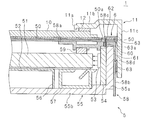
- FIG. 2 is a partial sectional view taken along line AA in FIG.
- the cross section of the frame 11 is L-shaped, and the frame 11 is connected to the front wall portion 11b that covers the front peripheral portion of the display panel 10 and the peripheral wall that is connected to the front wall portion 11b and covers the end surface of the display panel 10. Part 11c.
- a cushioning material 12 is disposed between the front wall portion 11 b of the frame 11 and the peripheral edge portion of the display panel 10.
- the display device 1 further includes a backlight device 5 on the rear side of the display panel 10, and the backlight device 5 emits light from the rear side of the display panel 10 toward the front side.
- the display panel 10 is irradiated with light from the rear side by the backlight device 5 and displays an image on the display surface.
- the display panel 10 is a liquid crystal panel, for example.
- the backlight device 5 includes a rectangular optical sheet 50, a rectangular plate-shaped light guide plate 51, a rectangular reflective sheet 52, and a plurality of LEDs 53.
- the optical sheet 50 is configured by laminating a plurality of sheets having various optical functions such as a field-of-view expanding sheet and an antireflection sheet, and is disposed in a state where one surface is in close contact with the rear surface of the display panel 10. .
- the light guide plate 51 is disposed on the rear side of the optical sheet 50, and the front surface of the light guide plate 51 that forms one plane faces the optical sheet 50.
- a reflective sheet 52 is in close contact with the rear surface of the light guide plate 51, and a plurality of LEDs 53 are arranged in a left-right direction (a direction perpendicular to the paper surface of FIG. 2) at a position facing the upper end surface (right side of the drawing) of the light guide plate 51.
- the light guide plates 51 are juxtaposed along the longitudinal direction of the upper end surface.
- Each of the plurality of LEDs 53 functions as a light source and emits light in a direction indicated by an arrow, and the light emitted by each of the plurality of LEDs 53 is incident on the upper end surface of the light guide plate 51.
- the light guide plate 51 is made of, for example, acrylic resin, and light incident on the upper end surface of the light guide plate 51 is repeatedly reflected on the front surface and the rear surface. When light propagating through the light guide plate 51 is reflected by the front surface of the light guide plate 51, part of the light is emitted toward the optical sheet 50. Since the rear surface of the light guide plate 51 is in close contact with the reflection sheet 52, all light propagating through the light guide plate 51 is reflected on the rear surface. Thereby, the light guide plate 51 emits uniform light from the front surface forming one plane toward the optical sheet 50.
- a rectangular plate-shaped LED substrate 54 is disposed above the plurality of LEDs 53, the lower surface of the LED substrate 54 faces the upper end surface of the light guide plate 51, and the plurality of LEDs 53 are mounted on the lower surface of the LED substrate 54. Yes.
- the upper surface of the LED board 54 is in close contact with the heat radiating body 55, and heat generated in the LED board 54 due to light emission of the plurality of LEDs 53 is transmitted through the heat radiating body 55.
- the heat radiating body 55 has an L-shaped cross section, and the heat radiating body 55 covers the upper end surface of the light guide plate 51 and is in close contact with the LED substrate 54, and is connected to the upper wall 55a. And a rear wall portion 55b disposed on the rear side of the light guide plate 51. The rear wall portion 55b of the radiator 55 is exposed to the outside air, and the heat generated in the LED substrate 54 is transmitted to the rear wall portion 55b through the upper wall portion 55a and is released from the rear wall portion 55b into the outside air. .
- a backlight chassis 56 is disposed between the rear wall portion 55 b of the radiator 55 and the reflection sheet 52, and the backlight chassis 56 supports the light guide plate 51 and the reflection sheet 52.
- a spacer 57 is disposed between the rear surface of the light guide plate 51 and the reflective sheet 52, that is, between the peripheral portion on the LED 53 side and the rear wall portion 55b.
- the backlight device 5 further includes a cover 58 that covers the plurality of LEDs 53 and the upper side of the front peripheral edge of the light guide plate 51.
- the cover 58 is disposed between the front surface of the light guide plate 51 and the optical sheet 50, and the cover 58 has an L-shaped cross section.
- the cover 58 is connected to the first cover 58a that covers the upper peripheral edge of the front surface of the light guide plate 51, and the first cover 58a.
- the cover 58 is disposed above the light guide plate 51 from the upper side of the upper wall portion 55a of the radiator 55. And a second cover portion 58b covering the end surface.
- a buffer material 59 is disposed between the first cover portion 58 a of the cover body 58 and the front surface of the light guide plate 51.
- a part of the upper side of the optical sheet 50 is extended upward from the display panel 10, and the optical sheet 50 has a through hole 50a penetrating in the front-rear direction in the extended part of the upper side.
- the first cover 58a of the cover 58 is provided with a first hole 58c that penetrates in the front-rear direction and communicates with the through hole 50a, and the second cover 58b has a second hole that penetrates in the vertical direction. 58d.
- the backlight device 5 further includes a regulating member 6 that engages with the optical sheet 50 and the cover body 58 and regulates movement in the surface direction by the optical sheet 50.
- the restriction member 6 is provided with a first insertion portion 60 that is inserted into a through hole 50 a provided in the optical sheet 50 and a first hole 58 c provided in the first cover portion 58 a of the cover body 58.
- the restricting member 6 is provided with a second insertion portion 61 that is inserted into a second hole 58 d provided in the second cover portion 58 b of the cover body 58.
- the restricting member 6 is further connected to the first insertion portion 60, connected to the front wall portion 62 disposed on the front side of the optical sheet 50, the second insertion portion 61 and the front wall portion 62, and the cover 58. And an upper wall portion 63 disposed on the upper side of the second cover portion 58b.
- the front wall part 62 and the upper wall part 63 connect the first insertion part 60 and the second insertion part 61 and function as a connection part.
- the restricting member 6 inserts the first insertion portion 60 into the through hole 50a and the first hole 58c, and is connected to the first insertion portion 60 by the front wall portion 62 and the upper wall portion 63.
- the optical sheet 50 and the cover 58 are engaged. Note that a portion of the peripheral wall portion 11 c of the frame 11 that covers the upper end surface of the display panel 10 is located above the upper wall portion 63 of the regulating member 6.
- FIG. 3 is a perspective view of the regulating member 6 viewed from one side
- FIG. 4 is a perspective view of the regulating member 6 viewed from the other side.
- each of the first insertion portion 60 and the front wall portion 62 of the restricting member 6 has a rectangular plate shape, and the front wall portion 62 extends from one long side of the first insertion portion 60.
- One long side of the front wall portion 62 is connected to one long side of the first insertion portion 60 and protrudes in a direction perpendicular to the one insertion portion 60.
- the upper wall portion 63 has a rectangular plate shape and is provided with a rectangular opening 63a at the center.
- the front wall portion 62 extends from one side of the outer side of the upper wall portion 63 in a direction perpendicular to the upper wall portion 63. Projected. One side of the outer side of the upper wall part 63 is connected to the other long side of the front wall part 62, and the upper wall part 63 faces the first insertion part 60.
- one side of the second insertion portion 61 having a rectangular plate shape is connected to one side of the opening 63a.
- the second insertion portion 61 is disposed such that the plate surface is located below the plate surface of the upper wall portion 63, that is, on the first insertion portion 60 side.
- the restricting member 6 can be created using either resin or sheet metal as long as it has elasticity.
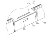
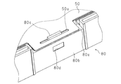
- FIG. 5 is a perspective view of the backlight device 5 with the regulating member 6 removed.
- the optical sheet 50 is disposed on the front side of the first cover 58a in the cover 58.
- the second cover portion 58 b of the cover body 58 has a portion extending to the front side from the first cover portion 58 a and a portion not extending to the front side from the first cover portion 58 a.
- a recess 58e is provided on the front side of the second cover 58b.
- a part of the upper side of the optical sheet 50 extends upward, and as shown in FIG. 5, the extended part of the optical sheet 50 is disposed in the recess 58e of the cover 58, A rectangular through hole 50 a is provided in the extending portion of the sheet 50.
- the longitudinal direction of the through hole 50a substantially coincides with the longitudinal direction of the optical sheet 50, that is, the left-right direction.
- the second cover portion 58b of the cover body 58 has a rectangular plate shape whose longitudinal direction substantially coincides with the left-right direction, and the second cover portion 58b has a rectangular second hole 58d. Is provided.
- the second hole 58d is provided at a position corresponding to the central portion in the left-right direction of the recess 58e in the second cover 58b.
- the optical sheet 50 is disposed on the front side of the cover 58
- the second hole 58d corresponds to the central portion in the left-right direction of the through hole 50a of the optical sheet 50.
- the AA line described above is a vertical line passing through the center in the left-right direction of the through hole 50a and the second hole 58d.
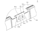
- FIG. 6 is a perspective view of the backlight device 5 to which the regulating member 6 is attached
- FIG. 7 is a cross-sectional perspective view showing a part of the backlight device 5.
- the restricting member 6 the first insertion portion 60 is inserted into the through hole 50 a of the optical sheet 50 and the first hole 58 c provided in the first cover portion 58 a of the cover body 58.
- the second insertion portion 61 By inserting the second insertion portion 61 into the second hole 58d provided in the second cover portion 58b of the cover body 58, the optical sheet 50 and the cover body 58 are engaged with each other. At this time, the lower surface of the second insertion portion 61 faces the upper wall portion 55a of the heat radiator 55.
- the restricting member 6 By inserting the second insertion portion 61 of the restricting member 6 into the second hole 58d provided in the second cover portion 58b of the cover 58, the restricting member 6 is in the front-rear direction and the left-right direction with respect to the cover 58 That is, the movement in the surface direction of the second cover portion 58b is prevented.
- the distance between the first insertion portion 60 and the upper wall portion 63 is slightly larger than the distance from the upper end of the optical sheet 50 to the upper side of the through hole 50a. Further, the distance in the left-right direction of the front wall portion 62 in the restricting member 6 is slightly smaller than the distance in the left-right direction of the through hole 50 a in the optical sheet 50. Thereby, the thermal expansion of the optical sheet 50 can be permitted.
- the optical sheet 50 does not move greatly in the vertical direction and the left-right direction with respect to the cover 58.
- the portion from the upper end to the upper side of the through hole 50 a is sandwiched between the front wall portion 62 of the regulating member 6 and the first cover portion 58 a of the cover body 58.
- the movement in the direction is suppressed, and the movement in the surface direction of the optical sheet 50 is restricted.
- the optical sheet 50 does not move in the vertical direction more than the difference between the distance between the first insertion portion 60 and the upper wall portion 63 and the distance from the upper end of the optical sheet 50 to the upper side of the through hole 50a. It does not move in the left-right direction more than the difference between the distance in the left-right direction of the front wall portion 62 and the distance in the left-right direction of the through hole 50a.
- the optical sheet 50 moves downward, the optical sheet 50 does not move further downward after the upper side of the through hole 50a of the optical sheet 50 and the first insertion portion 60 of the restricting member 6 come into contact with each other. Further, when the optical sheet 50 moves in the upward direction, the optical sheet 50 does not move further in the upward direction after the upper end of the optical sheet 50 comes into contact with the upper wall portion 63 of the regulating member 6.
- the left or right side of the through hole 50a of the optical sheet 50 does not move further leftward or rightward after contacting the first insertion portion 60 of the regulating member 6. Absent.
- the regulating member 6 regulates the movement of the optical sheet 50 in the surface direction, the optical sheet 50 is prevented from moving greatly due to vibration of the display device 1 or an impact applied to the display device 1. can do. Therefore, the optical sheet 50 does not move greatly, the display panel 10 is damaged, and the quality of the image displayed on the display panel 10 does not deteriorate. Further, the regulating member 6 can regulate the movement of the optical sheet 50 in the surface direction without using a screw by the engagement between the optical sheet 50 and the cover 58, and the backlight device 5 is inexpensive. Further, since it is not necessary to provide a space for screwing the screw, the backlight device 5 is small. The display device 1 including the small and inexpensive backlight device 5 is also small and inexpensive.
- each of the first insertion portion 60 and the second insertion portion 61 is not limited to a rectangular plate shape.
- the shape of the 1st insertion part 60 should just be a shape which can be inserted in the through-hole 50a of the optical sheet 50, and the 1st hole 58c provided in the 1st cover part 58a of the cover 58.
- the shape of the 2nd insertion part 61 should just be a shape which can be inserted in the 2nd hole 58d provided in the 2nd cover part 58b of the cover 58.
- the shape of the through hole 50a, the first hole 58c, and the second hole 58d is not limited to a rectangular shape.
- the shape of each of the through hole 50a and the first hole 58c may be any shape that allows the first insertion portion 60 to be inserted
- the shape of the second hole 58d may be any shape that allows the second insertion portion 61 to be inserted.
- restriction member 6 only needs to connect the first insertion portion 60 and the second insertion portion 61, and the upper wall portion 63 of the restriction member 6 that functions as a part of the connection portion is provided with an opening 63a.
- the shape may not be the same.
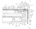
- FIG. 8 is a partial cross-sectional view of the display device according to the second embodiment.
- the display device 7 includes a display panel 10, a frame 11, and a cushioning material 12, similar to the display device 1 in the first embodiment.
- the display device 7 includes a backlight device 8 instead of the backlight device 5 in the first embodiment, and the backlight device 8 is disposed on the rear side of the display panel 10.
- the backlight device 8 irradiates light from the rear side to the front side of the display panel 10, and the display panel 10 is irradiated with light from the rear side by the backlight device 8. Display an image.
- the backlight device 8 includes an optical sheet 50, a light guide plate 51, a reflective sheet 52, a plurality of LEDs 53, an LED substrate 54, a radiator 55, a backlight chassis 56, and a spacer 57. And a buffer material 59.
- the backlight device 8 includes a cover 80 instead of the cover 58, and includes a restriction member 9 instead of the restriction member 6.
- the backlight device 8 is different from the backlight device 5 in the first embodiment in the configuration that regulates the optical sheet 50.
- the structure which controls the optical sheet 50 is demonstrated, the same code
- the optical sheet 50 faces the front surface of the light guide plate 51, and the light emitted from the plurality of LEDs 53 is the light guide plate 51.
- the light guide plate 51 emits uniform light toward the optical sheet 50 from the front surface.
- the optical sheet 50 has a through hole 50a as in the first embodiment.
- the cover 80 is disposed between the front surface of the light guide plate 51 and the optical sheet 50, similarly to the cover 58 in the first embodiment, and includes a plurality of LEDs 53 and the upper side of the peripheral edge of the front surface of the light guide plate 51. Covering.
- the cross section of the cover 80 is L-shaped.
- the cover 80 is connected to the first cover 80a covering the upper peripheral edge of the front surface of the light guide plate 51, and the first cover 80a.
- the cover 80 is disposed above the light guide plate 51 from above the upper wall portion 55a of the radiator 55. And a second cover portion 80b covering the end surface.
- a buffer material 59 is disposed between the first cover portion 80 a of the cover body 80 and the front surface of the light guide plate 51.
- a protrusion 80c is provided on the first cover 80a of the cover 80, and the protrusion 80c protrudes forward from the front surface of the first cover 80a.
- the protrusion 80 c is inserted through the through hole 50 a of the optical sheet 50.
- the second cover portion 80b is provided with a hole 80d penetrating in the vertical direction.
- the regulating member 9 engages with the optical sheet 50 and the cover 80 and regulates movement in the surface direction by the optical sheet 50.
- the regulating member 9 has an annular portion 90 disposed on the front side of the optical sheet 50, and the annular portion 90 engages with a protruding portion 80 c of the cover 80 that is inserted through the through hole 50 a of the optical sheet 50.
- the regulating member 9 is further disposed on the upper side of the upper wall portion 55a of the heat dissipating body 55 and the insertion portion 91 to be inserted into the hole 80d provided in the second cover portion 80b of the cover 80.
- a connecting portion 92 for connecting the portion 91.
- the annular portion 90 is engaged with the protruding portion 80 c of the cover 80 inserted through the through hole 50 a of the optical sheet 50, and the insertion portion 91 is the second cover portion of the cover 80.
- the optical sheet 50 and the cover 80 are engaged with each other.
- the portion of the peripheral wall portion 11 c of the frame 11 that covers the upper end surface of the display panel 10 is located above the connecting portion 92 of the regulating member 9.
- FIG. 9 is a perspective view of the regulating member 9.
- the annular portion 90 of the regulating member 9 has a rectangular plate shape, and has a rectangular opening 90 a at the center.
- One side constituting the opening 90 a is substantially parallel to one side forming the outer shape of the annular portion 90.
- the connecting portion 92 is formed in a rectangular plate shape and protrudes from the outer side of the annular portion 90 in a direction perpendicular to the plate surface of the annular portion 90, and a rectangular opening 92a is provided at the center portion.
- One side of the insertion portion 91 having a rectangular plate shape is connected to one side that forms the opening 92a of the connection portion 92.
- the plate surface of the insertion portion 91 is located below the plate surface of the connecting portion 92.
- the plate surface of the insertion portion 91 is positioned in the direction in which the annular portion 90 projects from the plate surface of the connection portion 92.
- the restriction member 9 can be formed using either resin or sheet metal as long as it has elasticity.
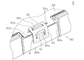
- FIG. 10 is a perspective view of the backlight device 8 with the regulating member 9 removed.
- the optical sheet 50 is disposed on the front side of the first cover 80 a in the cover 80.
- the second cover portion 80 b of the cover 80 has a portion that extends to the front side of the first cover portion 80 a and a portion that does not extend to the front side of the first cover portion 80 a.
- the second cover 80b is provided with a recess 80e on the front side.
- a part of the upper side of the optical sheet 50 is extended in the same manner as in the first embodiment, and the extended portion of the optical sheet 50 is disposed in the concave portion 80e of the cover 80, and is extended to the extended portion of the optical sheet 50.
- the longitudinal direction of the through hole 50a substantially coincides with the longitudinal direction of the optical sheet 50, that is, the left-right direction.
- the protruding portion 80c of the cover 80 has a rectangular plate shape, the plate surface of the protruding portion 80c is substantially orthogonal to the optical sheet 50, and the direction perpendicular to the plate surface of the protruding portion 80c is substantially aligned with the vertical direction. Yes.
- the protruding portion 80 c is inserted through the central portion in the left-right direction of the through hole 50 a of the optical sheet 50 and protrudes to the front side of the optical sheet 50.
- the second cover portion 80b of the cover body 80 has a rectangular plate shape whose longitudinal direction substantially coincides with the left-right direction, and a rectangular hole 80d is provided in the second cover portion 80b. ing.
- the hole 80d is provided in the second cover portion 80b at a position corresponding to the central portion in the left-right direction of the recess 80e.
- the hole 80d corresponds to the center portion in the left-right direction of the through hole 50a of the optical sheet 50 and the center portion in the left-right direction of the protruding portion 80c.
- FIG. 8 is a partial cross-sectional view taken along a vertical line passing through the central part in the left-right direction of the through hole 50a, the protrusion 80c, and the hole 80d.
- FIG. 11 is a perspective view of the backlight device 8 to which the regulating member 9 is attached
- FIG. 12 is a cross-sectional perspective view showing a part of the backlight device 8.
- the regulating member 9 engages the annular portion 90 and the projecting portion 80c by inserting the opening 90a into the projecting portion 80c of the cover 80 through which the through hole 50a of the optical sheet 50 is inserted.
- the rectangular plate-shaped insertion portion 91 into the hole 80d provided in the second cover portion 80b of the cover body 80, the optical sheet 50 and the cover body 80 are engaged with each other.
- the lower surface of the insertion portion 91 faces the upper wall portion 55a of the radiator 55.
- the restriction member 9 By inserting the insertion portion 91 of the restriction member 9 into the hole 80d provided in the second cover portion 80b of the cover body 80, the restriction member 9 is moved in the front-rear direction and the left-right direction, that is, in the first direction. The movement in the surface direction of the two cover portions 80b is prevented.
- the vertical and horizontal dimensions of the through-hole 50a of the optical sheet 50 are slightly larger than the vertical and horizontal dimensions of the front end surface of the protrusion 80c of the cover 80. Thereby, the thermal expansion of the optical sheet 50 can be permitted.
- the optical sheet 50 since the regulating member 9 is engaged with the optical sheet 50 and the cover 80, the optical sheet 50 does not move greatly in the vertical direction and the left-right direction with respect to the cover 80. Since a part of the upper peripheral edge portion of the optical sheet 50 is sandwiched between the annular portion 90 of the regulating member 9 and the first cover portion 80a of the cover body 80, the optical sheet 50 moves in the vertical direction and the horizontal direction. Is suppressed, and movement of the optical sheet 50 in the surface direction is restricted. Further, the optical sheet 50 does not move in the vertical direction more than the difference between the vertical distance of the protruding portion 80c and the vertical distance of the through hole 50a of the optical sheet 50, and the horizontal direction of the protruding portion 80c. It does not move in the left-right direction more than the difference between the distance and the distance in the left-right direction of the through hole 50a.
- the optical sheet 50 moves downward, the optical sheet 50 does not move further downward after the upper side of the through hole 50a of the optical sheet 50 and the protrusion 80c of the cover 80 are in contact with each other. Further, when the optical sheet 50 moves upward, the optical sheet 50 does not further move upward after the lower side of the through hole 50a of the optical sheet 50 and the protruding portion 80c come into contact with each other.
- the right or left side of the through hole 50a of the optical sheet 50 does not move further leftward or rightward after contacting the right side or left side of the protrusion 80c.
- the regulating member 9 regulates the movement of the optical sheet 50 in the surface direction by engaging the optical sheet 50 and the cover 80, in addition to the vibration of the display device 7 or the display device 7. It is possible to prevent the optical sheet 50 from moving greatly due to an impact or the like. Therefore, the optical sheet 50 does not move greatly, the display panel 10 is damaged, and the quality of the image displayed on the display panel 10 does not deteriorate. Further, the regulating member 9 can regulate the movement of the optical sheet 50 in the surface direction without using a screw by engaging the optical sheet 50 and the cover 80, and the backlight device 8 is inexpensive. Further, since it is not necessary to provide a space for screwing the screw, the backlight device 8 is small. Further, the display device 7 including the small and inexpensive backlight device 8 is also small and inexpensive.
- the shape of the opening 90a provided in the annular portion 90 of the regulating member 9 is not limited to a rectangular shape, and may be any shape as long as the protruding portion 80c of the cover 80 can be inserted.
- the shape of the protruding portion 80c is not limited to a rectangular plate shape, and may be any shape that can be inserted into the opening 90a.
- the shape of the insertion portion 91 is not limited to a rectangular plate shape, and may be a shape that can be inserted into the hole 80d provided in the second cover portion 80b of the cover 80.
- the shape of the hole 80d provided in the second cover portion 80b of the cover body 80 is not limited to a rectangular shape, and may be any shape as long as the insertion portion 91 can be inserted. Further, the regulating member 9 may be in a shape in which the annular portion 90 and the insertion portion 91 are connected, and the connecting portion 92 may not have a shape in which the opening 92a is provided.
- the light source that emits light to the upper end surface of the light guide plate 51 is not limited to the LED 53, and may be a cold cathode tube, for example.
Landscapes
- Physics & Mathematics (AREA)
- General Physics & Mathematics (AREA)
- Optics & Photonics (AREA)
- Nonlinear Science (AREA)
- Mathematical Physics (AREA)
- Chemical & Material Sciences (AREA)
- Crystallography & Structural Chemistry (AREA)
- Planar Illumination Modules (AREA)
- Liquid Crystal (AREA)
Abstract
Description
光学シートが大きく移動した場合、表示パネルに傷が付き、表示パネルが表示する画像の品位が低下する虞がある。
(実施の形態1)
図1は実施の形態1における表示装置の外観図である。この表示装置1は、前側に画像を表示する表示面を有する矩形板状の表示パネル10を備え、表示パネル10の前側の周縁部は、中央部に開口11aを有する矩形枠状のフレーム11によって覆われている。表示パネル10において、表示面の中央部に位置する有効表示領域は開口11aから露出している。
覆体58の第1覆部58aと導光板51の前面との間には緩衝材59が配置されている。
図8は、実施の形態2における表示装置の部分断面図である。この表示装置7は、実施の形態1における表示装置1と同様に、表示パネル10、フレーム11及び緩衝材12を備えている。表示装置7は、実施の形態1におけるバックライト装置5の代わりにバックライト装置8を備え、バックライト装置8は、表示パネル10の後側に配置されている。バックライト装置8は、バックライト装置5と同様に、表示パネル10の後側から前側に向けて光を照射し、表示パネル10は、バックライト装置8によって後側から光を照射されて表示面に画像を表示する。
10 表示パネル
5,8 バックライト装置
50 光学シート
50a 貫通孔
51 導光板
53 LED
58,80 覆体
58a,80a 第1覆部
58b,80b 第2覆部
58c 第1孔
58d 第2孔
6,9 規制部材
60 第1挿入部
61 第2挿入部
62 前壁部
63 上壁部
80c 突出部
80d 孔
90 環状部
91 挿入部
92 連結部
Claims (4)
- 光源と、該光源の光が端面に入射され、一平面から光を出射する導光板と、前記一平面に対向する光学シートと、前記導光板の前記一平面及び光学シートの間に配され、前記光源、及び、前記一平面の前記光源側の周縁部を覆う覆体とを備えるバックライト装置において、
前記光学シート及び覆体夫々に係合し、前記光学シートによる面方向の移動を規制する規制部材
を備えることを特徴とするバックライト装置。 - 前記光学シートは貫通孔を有し、
前記覆体は、前記周縁部を覆う第1覆部と、前記端面を覆う第2覆部と、前記第1覆部に設けられ、前記貫通孔に連通する第1孔と、前記第2覆部に設けられた第2孔とを有し、
前記規制部材は、前記貫通孔及び第1孔に挿入される第1挿入部と、前記第2孔に挿入される第2挿入部と、前記第1及び第2挿入部を連結する連結部とを有すること
を特徴とする請求項1に記載のバックライト装置。 - 前記光学シートは貫通孔を有し、
前記覆体は、前記周縁部を覆う第1覆部と、前記端面を覆う第2覆部と、前記第1覆部から突出し、前記貫通孔に挿通する突出部と、前記第2覆部に設けられた孔とを有し、
前記規制部材は、前記貫通孔を挿通した前記突出部と係合する環状部と、前記孔に挿入される挿入部と、前記環状部及び挿入部を連結する連結部とを有すること
を特徴とする請求項1に記載のバックライト装置。 - 画像を表示する表示パネルと、
該表示パネルに光を照射する請求項1から請求項3のいずれか1つに記載のバックライト装置と
を備えることを特徴とする表示装置。
Priority Applications (3)
| Application Number | Priority Date | Filing Date | Title |
|---|---|---|---|
| US14/764,796 US9977176B2 (en) | 2013-05-15 | 2014-04-22 | Backlight device and display apparatus |
| CN201480009520.7A CN105074323B (zh) | 2013-05-15 | 2014-04-22 | 背光装置以及显示装置 |
| JP2015517006A JP5977887B2 (ja) | 2013-05-15 | 2014-04-22 | バックライト装置及び表示装置 |
Applications Claiming Priority (2)
| Application Number | Priority Date | Filing Date | Title |
|---|---|---|---|
| JP2013103433 | 2013-05-15 | ||
| JP2013-103433 | 2013-05-15 |
Publications (1)
| Publication Number | Publication Date |
|---|---|
| WO2014185227A1 true WO2014185227A1 (ja) | 2014-11-20 |
Family
ID=51898207
Family Applications (1)
| Application Number | Title | Priority Date | Filing Date |
|---|---|---|---|
| PCT/JP2014/061248 Ceased WO2014185227A1 (ja) | 2013-05-15 | 2014-04-22 | バックライト装置及び表示装置 |
Country Status (4)
| Country | Link |
|---|---|
| US (1) | US9977176B2 (ja) |
| JP (1) | JP5977887B2 (ja) |
| CN (1) | CN105074323B (ja) |
| WO (1) | WO2014185227A1 (ja) |
Cited By (3)
| Publication number | Priority date | Publication date | Assignee | Title |
|---|---|---|---|---|
| JPWO2016084233A1 (ja) * | 2014-11-28 | 2017-08-31 | 堺ディスプレイプロダクト株式会社 | バックライト装置及び液晶表示装置 |
| WO2018051899A1 (ja) * | 2016-09-16 | 2018-03-22 | シャープ株式会社 | 表示装置及びテレビジョン受信機 |
| JP2018049810A (ja) * | 2016-09-16 | 2018-03-29 | シャープ株式会社 | 表示装置及びテレビジョン受信機 |
Families Citing this family (13)
| Publication number | Priority date | Publication date | Assignee | Title |
|---|---|---|---|---|
| TWI561868B (en) * | 2014-05-23 | 2016-12-11 | Radiant Opto Electronics Corp | Back plate assembly and backlight module |
| KR102164261B1 (ko) * | 2014-08-08 | 2020-10-13 | 엘지디스플레이 주식회사 | 광학시트 고정수단을 구비하는 액정표시장치 |
| KR102429136B1 (ko) * | 2015-10-30 | 2022-08-03 | 엘지디스플레이 주식회사 | 디스플레이 장치 |
| CN206906751U (zh) * | 2017-07-27 | 2018-01-19 | 深圳Tcl新技术有限公司 | 液晶显示设备 |
| CN107861270B (zh) * | 2017-09-19 | 2020-12-08 | 苏州乐轩科技有限公司 | 显示设备及其组装与拆卸方法 |
| CN108663841B (zh) * | 2018-05-08 | 2021-05-28 | 昆山龙腾光电股份有限公司 | 液晶显示装置及其制作方法 |
| CN208314417U (zh) * | 2018-05-30 | 2019-01-01 | 北京京东方技术开发有限公司 | 背光模组及显示装置 |
| JP7116674B2 (ja) * | 2018-12-04 | 2022-08-10 | ミネベアミツミ株式会社 | 面状照明装置 |
| CN110515235A (zh) * | 2019-08-06 | 2019-11-29 | 深圳市兆驰股份有限公司 | 液晶显示装置及其直下式背光模组和背板 |
| CN110824773B (zh) * | 2019-11-22 | 2022-08-30 | 京东方科技集团股份有限公司 | 一种背光组件、背光模组和显示面板 |
| CN113138478B (zh) * | 2020-01-20 | 2022-07-19 | 苏州佳世达电通有限公司 | 组装结构及应用其的显示装置 |
| US20220155634A1 (en) * | 2020-11-19 | 2022-05-19 | Dell Products, Lp | System and method to secure a narrow borderless display panel without cover glass |
| CN214151307U (zh) * | 2021-02-20 | 2021-09-07 | Oppo广东移动通信有限公司 | 壳体组件及显示设备 |
Citations (4)
| Publication number | Priority date | Publication date | Assignee | Title |
|---|---|---|---|---|
| JPH0990361A (ja) * | 1995-09-27 | 1997-04-04 | Toshiba Lighting & Technol Corp | バックライトおよびこれを用いた液晶表示装置 |
| JP2009117349A (ja) * | 2007-10-19 | 2009-05-28 | Fujifilm Corp | 面状照明装置 |
| JP2013037974A (ja) * | 2011-08-10 | 2013-02-21 | Seiko Epson Corp | 照明装置、液晶表示装置および電子機器 |
| JP2013242368A (ja) * | 2012-05-18 | 2013-12-05 | Sharp Corp | 表示装置、及びテレビ受信装置 |
Family Cites Families (11)
| Publication number | Priority date | Publication date | Assignee | Title |
|---|---|---|---|---|
| JP2002196312A (ja) * | 2000-12-25 | 2002-07-12 | Hitachi Ltd | 液晶表示装置 |
| KR100757794B1 (ko) * | 2001-09-03 | 2007-09-11 | 삼성전자주식회사 | 액정 표시 모듈 및 이를 갖는 액정 표시 장치 |
| KR100852167B1 (ko) * | 2002-03-08 | 2008-08-13 | 삼성전자주식회사 | 평판 표시 장치 |
| KR100840715B1 (ko) * | 2002-05-28 | 2008-06-23 | 삼성전자주식회사 | 백 라이트 어셈블리 및 이를 갖는 액정 표시 장치 |
| KR20040009902A (ko) * | 2002-07-26 | 2004-01-31 | 삼성전자주식회사 | 백라이트 어셈블리 및 액정표시장치 |
| JP4084766B2 (ja) | 2004-03-26 | 2008-04-30 | シャープ株式会社 | バックライト装置 |
| WO2010004822A1 (ja) * | 2008-07-11 | 2010-01-14 | シャープ株式会社 | 照明装置、表示装置、テレビ受信装置 |
| JP5178460B2 (ja) * | 2008-11-04 | 2013-04-10 | 富士フイルム株式会社 | 面状照明装置 |
| CN201875645U (zh) * | 2010-10-22 | 2011-06-22 | 北京京东方光电科技有限公司 | 光学膜片固定件和光学膜片固定结构 |
| CN102352986A (zh) * | 2011-08-15 | 2012-02-15 | 青岛海信电器股份有限公司 | 背光模组及液晶电视机 |
| CN103017098B (zh) * | 2012-10-10 | 2014-10-29 | 青岛海信电器股份有限公司 | 一种膜片定位结构、背光模组及显示设备 |
-
2014
- 2014-04-22 CN CN201480009520.7A patent/CN105074323B/zh active Active
- 2014-04-22 JP JP2015517006A patent/JP5977887B2/ja not_active Expired - Fee Related
- 2014-04-22 WO PCT/JP2014/061248 patent/WO2014185227A1/ja not_active Ceased
- 2014-04-22 US US14/764,796 patent/US9977176B2/en not_active Expired - Fee Related
Patent Citations (4)
| Publication number | Priority date | Publication date | Assignee | Title |
|---|---|---|---|---|
| JPH0990361A (ja) * | 1995-09-27 | 1997-04-04 | Toshiba Lighting & Technol Corp | バックライトおよびこれを用いた液晶表示装置 |
| JP2009117349A (ja) * | 2007-10-19 | 2009-05-28 | Fujifilm Corp | 面状照明装置 |
| JP2013037974A (ja) * | 2011-08-10 | 2013-02-21 | Seiko Epson Corp | 照明装置、液晶表示装置および電子機器 |
| JP2013242368A (ja) * | 2012-05-18 | 2013-12-05 | Sharp Corp | 表示装置、及びテレビ受信装置 |
Cited By (4)
| Publication number | Priority date | Publication date | Assignee | Title |
|---|---|---|---|---|
| JPWO2016084233A1 (ja) * | 2014-11-28 | 2017-08-31 | 堺ディスプレイプロダクト株式会社 | バックライト装置及び液晶表示装置 |
| WO2018051899A1 (ja) * | 2016-09-16 | 2018-03-22 | シャープ株式会社 | 表示装置及びテレビジョン受信機 |
| JP2018049810A (ja) * | 2016-09-16 | 2018-03-29 | シャープ株式会社 | 表示装置及びテレビジョン受信機 |
| JP2018107822A (ja) * | 2016-09-16 | 2018-07-05 | シャープ株式会社 | 表示装置及びテレビジョン受信機 |
Also Published As
| Publication number | Publication date |
|---|---|
| JPWO2014185227A1 (ja) | 2017-02-23 |
| CN105074323A (zh) | 2015-11-18 |
| US20160011364A1 (en) | 2016-01-14 |
| JP5977887B2 (ja) | 2016-08-24 |
| US9977176B2 (en) | 2018-05-22 |
| CN105074323B (zh) | 2017-04-19 |
Similar Documents
| Publication | Publication Date | Title |
|---|---|---|
| JP5977887B2 (ja) | バックライト装置及び表示装置 | |
| US7787069B2 (en) | Display device and manufacturing method thereof | |
| JP5032650B2 (ja) | テレビおよび電子機器 | |
| JP2012208254A (ja) | 表示装置用照明装置および表示装置 | |
| JP6469583B2 (ja) | バックライト装置及び表示装置 | |
| JP2014149529A (ja) | ディスプレイモジュール及びそれを備えたディスプレイ装置 | |
| JP5064602B2 (ja) | 表示装置 | |
| JPWO2017126455A1 (ja) | ヘッドアップディスプレイ装置とレンズユニット | |
| WO2010016322A1 (ja) | 照明装置およびそれを備えた液晶表示装置 | |
| CN104520635A (zh) | 背光装置以及显示装置 | |
| WO2017037856A1 (ja) | 表示装置 | |
| WO2015045814A1 (ja) | 光源モジュール及び表示装置 | |
| JP2013218125A (ja) | 液晶表示装置 | |
| WO2016009543A1 (ja) | 表示装置 | |
| WO2015037404A1 (ja) | 表示装置 | |
| JP2010122330A (ja) | 液晶表示装置 | |
| WO2013069552A1 (ja) | 照明装置およびそれを備えた表示装置 | |
| WO2013024896A1 (ja) | 照明装置およびそれを備えた表示装置 | |
| JP6146032B2 (ja) | 表示装置 | |
| WO2014148363A1 (ja) | バックライト装置、及び表示装置 | |
| US20160223852A1 (en) | Liquid crystal display device | |
| WO2011016268A1 (ja) | 表示装置 | |
| TWI405102B (zh) | 背光模組與光學式觸控面板 | |
| JP2013196931A (ja) | 照明装置、表示装置、及びテレビ受信装置 | |
| JP2014059955A (ja) | 照明装置およびそれを備えた表示装置 |
Legal Events
| Date | Code | Title | Description |
|---|---|---|---|
| WWE | Wipo information: entry into national phase |
Ref document number: 201480009520.7 Country of ref document: CN |
|
| 121 | Ep: the epo has been informed by wipo that ep was designated in this application |
Ref document number: 14797967 Country of ref document: EP Kind code of ref document: A1 |
|
| WWE | Wipo information: entry into national phase |
Ref document number: 14764796 Country of ref document: US |
|
| ENP | Entry into the national phase |
Ref document number: 2015517006 Country of ref document: JP Kind code of ref document: A |
|
| NENP | Non-entry into the national phase |
Ref country code: DE |
|
| 122 | Ep: pct application non-entry in european phase |
Ref document number: 14797967 Country of ref document: EP Kind code of ref document: A1 |