WO2014185107A1 - 電解加工工具、電解加工システム、及び孔空き部材の製造方法 - Google Patents
電解加工工具、電解加工システム、及び孔空き部材の製造方法 Download PDFInfo
- Publication number
- WO2014185107A1 WO2014185107A1 PCT/JP2014/053545 JP2014053545W WO2014185107A1 WO 2014185107 A1 WO2014185107 A1 WO 2014185107A1 JP 2014053545 W JP2014053545 W JP 2014053545W WO 2014185107 A1 WO2014185107 A1 WO 2014185107A1
- Authority
- WO
- WIPO (PCT)
- Prior art keywords
- insulating
- electrode
- circumferential direction
- electrochemical machining
- workpiece
- Prior art date
- Legal status (The legal status is an assumption and is not a legal conclusion. Google has not performed a legal analysis and makes no representation as to the accuracy of the status listed.)
- Ceased
Links
Images



Classifications
-
- B—PERFORMING OPERATIONS; TRANSPORTING
- B23—MACHINE TOOLS; METAL-WORKING NOT OTHERWISE PROVIDED FOR
- B23H—WORKING OF METAL BY THE ACTION OF A HIGH CONCENTRATION OF ELECTRIC CURRENT ON A WORKPIECE USING AN ELECTRODE WHICH TAKES THE PLACE OF A TOOL; SUCH WORKING COMBINED WITH OTHER FORMS OF WORKING OF METAL
- B23H9/00—Machining specially adapted for treating particular metal objects or for obtaining special effects or results on metal objects
- B23H9/14—Making holes
- B23H9/16—Making holes using an electrolytic jet
-
- B—PERFORMING OPERATIONS; TRANSPORTING
- B23—MACHINE TOOLS; METAL-WORKING NOT OTHERWISE PROVIDED FOR
- B23H—WORKING OF METAL BY THE ACTION OF A HIGH CONCENTRATION OF ELECTRIC CURRENT ON A WORKPIECE USING AN ELECTRODE WHICH TAKES THE PLACE OF A TOOL; SUCH WORKING COMBINED WITH OTHER FORMS OF WORKING OF METAL
- B23H3/00—Electrochemical machining, i.e. removing metal by passing current between an electrode and a workpiece in the presence of an electrolyte
- B23H3/04—Electrodes specially adapted therefor or their manufacture
-
- B—PERFORMING OPERATIONS; TRANSPORTING
- B23—MACHINE TOOLS; METAL-WORKING NOT OTHERWISE PROVIDED FOR
- B23H—WORKING OF METAL BY THE ACTION OF A HIGH CONCENTRATION OF ELECTRIC CURRENT ON A WORKPIECE USING AN ELECTRODE WHICH TAKES THE PLACE OF A TOOL; SUCH WORKING COMBINED WITH OTHER FORMS OF WORKING OF METAL
- B23H9/00—Machining specially adapted for treating particular metal objects or for obtaining special effects or results on metal objects
- B23H9/10—Working turbine blades or nozzles
-
- B—PERFORMING OPERATIONS; TRANSPORTING
- B23—MACHINE TOOLS; METAL-WORKING NOT OTHERWISE PROVIDED FOR
- B23H—WORKING OF METAL BY THE ACTION OF A HIGH CONCENTRATION OF ELECTRIC CURRENT ON A WORKPIECE USING AN ELECTRODE WHICH TAKES THE PLACE OF A TOOL; SUCH WORKING COMBINED WITH OTHER FORMS OF WORKING OF METAL
- B23H9/00—Machining specially adapted for treating particular metal objects or for obtaining special effects or results on metal objects
- B23H9/14—Making holes
Definitions
- the present invention relates to an electrolytic processing tool for electrolytically processing a workpiece by energizing an electrode and the workpiece via an electrolytic solution, and an electrolytic processing system including the electrolytic processing tool.
- Drilling of difficult-to-cut materials that are difficult to machine is generally performed by electrolytic machining or electrical discharge machining.
- an electrolytic machining method is used when drilling a difficult-to-cut material having a high aspect ratio (for example, Patent Document 1).
- the applied voltage is increased in order to increase the current, but it is preferable to keep the applied voltage small from the viewpoint of energy saving for safety.
- the present invention provides an electrolytic machining tool, an electrolytic machining system, and a method for manufacturing a perforated member that can perform electrolytic machining while increasing the current-carrying area and suppressing the short-circuit frequency.
- the electrolytic processing tool is made of a conductive material having flexibility in the form of a cylinder extending along the axis, and an electrode through which an electrolyte flows toward the tip side inside, A tool body having an insulating layer coated on an outer peripheral surface of the electrode so as to expose a tip surface of the electrode, and a non-insulating portion exposing the outer peripheral surface of the electrode is formed on the tool body, the non-insulating The portion is sandwiched between the insulating layers from at least one of the axial direction and the circumferential direction.
- the workpiece is electrolyzed and the machining hole is machined deeper by energizing between the tip surface of the electrode and the inner surface of the machining hole of the workpiece via the electrolytic solution.
- the non-insulating part is formed so as to be sandwiched between the insulating layers, the frequency with which the non-contact part directly contacts the workpiece can be reduced.
- the non-insulating portion in the first aspect is formed in a ring shape that extends over the entire area in the circumferential direction around the axis, and is insulated from the axial direction. It may be sandwiched between layers.
- the insulating layer sandwiching the non-insulating part from the axial direction suppresses the contact of the non-insulating part with the workpiece. Therefore, it is possible to suppress the frequency of short circuits while increasing the energization area.
- the insulating layer sandwiching the non-insulating part from the axial direction suppresses the contact of the non-insulating part with the workpiece. Therefore, it is possible to suppress the frequency of short circuits while increasing the energization area.
- the total area of the non-insulating portions can be reduced. Can be bigger. In this case as well, the short-circuit frequency can be suppressed by the alternately arranged insulating layers while ensuring a current-carrying area.
- the non-insulating portion in the first aspect is formed so as to extend from the tip end of the tool body to the rear end side in the axial direction, and from the circumferential direction. It may be sandwiched between the insulating layers.
- the insulating layer sandwiching the non-insulating portion from the circumferential direction suppresses the contact of the non-insulating portion with the workpiece. Therefore, the energization area can be increased and the frequency of short circuits can be suppressed.
- a plurality of the non-insulating portions in the third aspect may be formed at intervals in the circumferential direction.
- the current-carrying area can be further increased while suppressing the short-circuit frequency. Therefore, it leads to further suppression of the applied voltage.
- the non-insulating portion in the first aspect is formed so as to extend in the axial direction, and is sandwiched between the insulating layer from the circumferential direction and the axial direction. It may be.
- a plurality of the non-insulating portions in the fifth aspect may be formed at intervals in the circumferential direction.
- the energization area can be further increased while the frequency of short circuits can be suppressed. Therefore, it leads to further suppression of the applied voltage.
- An electrolytic machining system is such that the electrolytic machining tool according to any one of the first to sixth aspects and the electrolytic machining tool are in a predetermined traveling direction with respect to a workpiece. And a moving mechanism for advancing the electrolytic processing tool.
- the non-insulating part is formed so as to be sandwiched between insulating layers in the electrolytic processing tool. For this reason, the frequency with which a non-contact part contacts a workpiece directly can be reduced. Therefore, it is possible to perform electrolytic processing while suppressing the short-circuit frequency while increasing the energization area.
- a machining hole is formed in a workpiece using the electrolytic machining tool according to any one of the first to sixth aspects.
- the non-insulating part is formed so as to be sandwiched between the insulating layers in the electrolytic processing tool. For this reason, the frequency with which a non-contact part contacts a workpiece directly can be reduced. Therefore, it is possible to perform electrolytic processing while increasing the energization area and suppressing the short-circuit frequency.
- the non-insulating portion is sandwiched between the insulating layers from at least one of the axial direction and the circumferential direction, thereby increasing the current-carrying area and the short-circuit frequency. Electrolytic machining can be performed while suppressing the above.
- FIG. 1 is an overall schematic diagram showing an electrolytic processing system according to a first embodiment of the present invention.
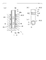
- the electrochemical processing system which concerns on 1st embodiment of this invention is shown, (a) is a longitudinal cross-sectional view which shows an electrolytic processing tool and a workpiece, (b) is A1 arrow directional view of (a), (c) ) Is a sectional view taken along line A2-A2 of FIG.
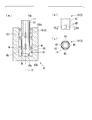
- the electrolytic processing system which concerns on 2nd embodiment of this invention is shown, (a) is a longitudinal cross-sectional view which shows an electrolytic processing tool and a workpiece, (b) is a B1 arrow directional view of (a), (c) ) Is a B2-B2 cross-sectional view of (b).
- the electrolytic processing system which concerns on the modification of 2nd embodiment of this invention is shown, (a) is a longitudinal cross-sectional view which shows an electrolytic processing tool and a workpiece, (b) is a B11 arrow line view of (a). (C) is a B21-B21 sectional view of (b).
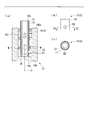
- the electrolytic processing system which concerns on 3rd embodiment of this invention is shown, (a) is a longitudinal cross-sectional view which shows an electrolytic processing tool and a workpiece, (b) is C1 arrow directional view of (a), (c) ) Is a C2-C2 cross-sectional view of (b).
- the electrolytic processing system which concerns on 4th embodiment of this invention is shown, (a) is a longitudinal cross-sectional view which shows an electrolytic processing tool and a workpiece, (b) is the D1 arrow line view of (a), (c) ) Is a sectional view taken along the line D2-D2 of FIG.
- the electrolytic processing system which concerns on 5th embodiment of this invention is shown, (a) is a longitudinal cross-sectional view which shows an electrolytic processing tool and a workpiece, (b) is E1 arrow line view of (a), (c) ) Is an E2-E2 cross-sectional view of (b).
- the electrolytic processing system 1 is an apparatus that forms a linear processing hole 101 in a workpiece 100.
- the workpiece 100 is a turbine blade of a gas turbine
- the machining hole 101 of the workpiece 100 is a cooling hole for cooling the turbine blade.
- the manufacturing method of the workpiece 100 having the processing hole 101 that is, the manufacturing method of the perforated member will be described.
- the electrolytic processing system 1 includes a plurality of electrolytic processing tools 3 that form processing holes 101 in a workpiece 100, a moving mechanism 4 that advances the electrolytic processing tools 3, and an electrolytic processing tool 3. And a guide portion 5 that guides the electrolytic processing tool 3 when the process proceeds.
- the moving mechanism 4 may have a function of rotating the electrolytic processing tool 3, and the electrolytic processing system 1 has not only a configuration including a plurality of electrolytic processing tools 3 but also a configuration including a single electrolytic processing tool 3. There may be.
- the moving mechanism 4 moves the electrolytic machining tool 3 forward and backward with respect to the workpiece 100.
- the moving mechanism 4 of the present embodiment is disposed on the tip 100a side of the turbine blade that is the workpiece 100, and can move forward and backward with respect to the tip 100a.
- the moving mechanism 4 may be advanced while rotating the electrolytic processing tool 3.
- the moving mechanism 4 moves the electrolytic processing tool 3 forward and backward using a driving source such as an electric motor (not shown).
- This moving mechanism 4 has a plurality of gripping portions 4a for gripping the base end (base end 10b described later) of the electrolytic processing tool 3 on the surface on the workpiece 100 side.
- the gripping portion 4a has a cylindrical shape whose inside is hollow, and the electrolytic processing tool 3 can be gripped by inserting the base end of the electrolytic processing tool 3 into one end side thereof.
- the other end side of the grip portion 4a is connected to an electrolyte flow passage (not shown), and the electrolyte W (see FIG. 2) is supplied into the grip portion 4a through the electrolyte flow passage.
- the supply amount of the electrolytic solution W can be arbitrarily adjusted by a flow rate control device (not shown).
- As the electrolytic solution W for example, sulfuric acid, nitric acid, saline, or the like is used.
- the guide unit 5 is disposed between the moving mechanism 4 and the tip 100a of the workpiece 100 (the tip shroud of the turbine blade).
- the guide unit 5 guides the electrochemical machining tool 3 advanced / retreated by the moving mechanism 4 with respect to the tip 100a of the workpiece 100 so as to be in a predetermined traveling direction.
- the guide portion 5 is provided with a plurality of guide holes 5a that allow the moving mechanism 4 side and the workpiece 100 side to communicate with each other.
- the electrolytic machining tool 3 is inserted through the guide holes 5a from the moving mechanism 4 side toward the workpiece 100 side.
- the electrolytic processing tool 3 is advanced by the moving mechanism 4, so that a desired angle at the distal end 100a of the workpiece 100 and a desired angle with respect to the distal end 100a according to the arrangement of the guide holes 5a.
- the electrolytic processing tool 3 can be introduced.
- the electrolytic processing tool 3 forms a machining hole (turbine blade cooling hole) 101 in a workpiece 100 by electrolytic machining.
- the electrolytic processing tool 3 includes an electrode 11 and an insulating layer 12 that covers the electrode 11 from the outer periphery, and includes a tool body 10 that has a cylindrical shape as a whole. As shown in FIG. 2, the tool body 10 is formed with a non-insulating portion 15 where the electrode 11 is exposed without a part of the outer peripheral surface being covered with the insulating layer 12.
- the electrode 11 in the tool body 10 has a cylindrical shape extending along the axis O, and is formed of a flexible conductive material such as stainless steel, copper, or titanium.
- the hollow portion inside the electrode 11 (inside the electrode 11) communicates with the hollow portion of the grip portion 4a of the moving mechanism 4.
- an electrolytic solution W to be subjected to electrolytic processing flows from the proximal end 10b side (moving mechanism 4 side) of the tool body 10 toward the distal end 10a side (workpiece 100 side). To do.
- the end face of the electrode 11 on the tip 10a side has a flat shape or a taper shape orthogonal to the axis O (flat shape in this embodiment).
- the electrode 11 has a cylindrical shape, but may have, for example, a rectangular shape with a polygonal cross section.
- the insulating layer 12 in the tool body 10 is made of, for example, a polyester resin having electrical insulation.
- the insulating layer 12 is coated on the outer peripheral surface of the electrode 11.
- the end face of the electrode 11 on the tip 10a side is not covered with the insulating layer 12, and the electrode 11 is exposed.
- the non-insulating portion 15 is exposed in a ring shape with the axis O as the center in the entire circumferential direction at a midway position near the tip 10a between the tip 10a and the base end 10b of the tool body 10. Thus, it is formed so as to face the workpiece 100 in the radial direction. That is, the non-insulating portion 15 is formed so as to be sandwiched between the insulating layers 12 from the direction of the axis O. In the present embodiment, two non-insulating portions 15 are formed at intervals in the axis O direction. Note that the number of non-insulating portions 15 is not limited to two as in the present embodiment, and at least one may be formed.
- non-insulating part 15 can be energized between the workpiece 100 via the electrolytic solution W derived from the tip 10a of the tool body 10.
- the electrolytic solution W is circulated from the tip 10 a of the tool body 10 by the electrolytic machining tool 3. Then, through the derived electrolyte W, an electric current is passed between the end surface of the tip 10a of the tool body 10 and the inner surface of the machining hole 101 of the workpiece 100, and the workpiece 100 is electrolyzed to form a machining hole. 101 is processed deeper in the direction of the axis O.
- the non-insulating portion 15 is formed during machining, current is supplied to the workpiece 100 not only on the end surface facing the direction of the axis O at the tip 10a of the tool body 10 but also on the outer peripheral surface of the electrode 11. It becomes possible. For this reason, the energization area between the workpiece 100 is increased, and the machining speed can be improved while suppressing the increase in applied voltage.
- the non-insulating part 15 is formed so as to be sandwiched by the insulating layer 12 from the direction of the axis O. For this reason, this insulating layer 12 can reduce the contact frequency to the workpiece 100 of the non-insulating part 15.
- this insulating layer 12 can reduce the contact frequency to the workpiece 100 of the non-insulating part 15.
- the non-insulating portion 15 is formed so as to be sandwiched from the direction of the axis O in the insulating layer 12, thereby increasing the current-carrying area and suppressing the short-circuit frequency. 100 electrolytic machining is possible.
- the non-insulating portion 25 has a rectangular shape on the outer peripheral surface of the electrode 11 when viewed from the radial direction.
- the non-insulating portion 25 is formed extending in the direction of the axis O so as to be continuous with the exposed portion of the electrode 11 on the end face of the tip 10a of the tool body 10.
- the non-insulating part 25 is formed so as to be sandwiched between the insulating layers 12 from the circumferential direction.
- a plurality of the non-insulating portions 25 are formed so as to alternate with the insulating layers 12 in the circumferential direction at a certain interval in the circumferential direction. In the present embodiment, four are formed as shown in FIG.
- the non-insulating portion 25 can energize the workpiece 100 even on the outer peripheral surface of the electrode 11. For this reason, an energization area can be increased. Furthermore, the insulating layer 12 that sandwiches the non-insulating part 25 from the circumferential direction suppresses the contact of the non-insulating part 25 with the workpiece 100. Therefore, it is possible to suppress the short-circuit frequency while securing a current-carrying area with the workpiece 100.
- the applied area can be further increased while suppressing the short-circuit frequency, and the applied voltage can be further suppressed.
- the shape of the non-insulating portion 25 is not limited to the above-described quadrangular shape, and may be various shapes such as a circular shape and a polygonal shape as viewed from the radial direction. In other words, it may be formed so as to be sandwiched between the insulating layers 12 at least from the circumferential direction.
- the cross-sectional shape of the processed hole 101 is a flower shape that expands only at the position where the non-insulating portion 25 is formed.
- the electrolytic machining tool 3 may be rotated.
- the machining hole 101 has a cross-sectional shape close to a perfect circle.
- the plurality of non-insulating portions 25 ⁇ / b> A may be formed so as to incline toward one side in the circumferential direction as viewed from the radial direction toward the base end 10 b side.
- adjacent non-insulating portions 25A are formed to overlap in the circumferential direction at different positions in the axis O direction.
- the non-insulating portion 25A may be linearly inclined in the circumferential direction, or may be curved and formed in a spiral shape.
- only one non-insulating part 35 is formed which is the same as the non-insulating part 25 in the second embodiment. That is, there is a portion where the outer peripheral surface of the electrode 11 is exposed only at one place in the circumferential direction, and this exposed portion is sandwiched between the insulating layers 12 from the circumferential direction.
- the energization area between the workpiece 100 and the workpiece 100 can be increased by the non-insulating portion 35 as in the second embodiment.
- interposes the non-insulating part 35 from the circumferential direction suppresses the contact to the workpiece 100 of the non-insulating part 35.
- FIG. Therefore, it is possible to suppress the short-circuit frequency while securing a current-carrying area with the workpiece 100.
- the non-insulating portion 35 is formed only at one place in the circumferential direction. For example, by appropriately adjusting the rotational speed and the traveling speed of the electrolytic processing tool 3 in the moving mechanism 4, the processing of the processing hole 101 is performed. Can be performed reliably. For this reason, it is possible to perform electrolytic processing while omitting the trouble of forming the non-insulating part 35 as compared with the second embodiment.
- the shape of the non-insulating part 35 may be various shapes such as a circular shape and a polygonal shape when viewed from the radial direction.
- the non-insulating portion 45 has a rectangular shape on the outer peripheral surface of the electrode 11 when viewed from the radial direction.
- the non-insulating portion 45 is formed with the insulating layer 12 interposed between the exposed portion of the electrode 11 on the end face of the tip 10a of the tool body 10 and extends in the axis O direction.
- a plurality of non-insulating portions 45 are formed so as to alternate with the insulating layer 12 in the circumferential direction at a constant interval in the circumferential direction. In the present embodiment, four are formed as shown in FIG. Thereby, the non-insulating part 45 is formed so as to be sandwiched between the insulating layer 12 from the circumferential direction and the axis O direction.
- the non-insulating portion 45 can increase the current-carrying area between the workpiece 100 and the insulating layer 12 sandwiching the non-insulating portion 45 from the circumferential direction can suppress the short circuit frequency. Is possible.
- the insulating layer 12 is formed on the outer peripheral surface of the tip 10a of the tool body 10 by the non-insulating portion 45. Therefore, since a short circuit does not occur at the tip 10a of the tool body 10 that easily contacts the workpiece 100, the frequency of the short circuit can be further reduced.
- the current-carrying area is further increased while the short-circuit frequency is suppressed, and the processing speed can be improved.
- the shape of the non-insulating portion 45 is not limited to the above-described square shape, and may be various shapes such as a circular shape and a polygonal shape when viewed from the radial direction. In other words, it may be formed so as to be sandwiched between the insulating layers 12 at least from the circumferential direction.
- the non-insulating part 45 only needs to be sandwiched from the circumferential direction and the axis O direction, and may be formed in, for example, a lattice shape as viewed from the radial direction, or a slit shape extending in the axis O direction or the circumferential direction.
- the cross-sectional shape of the processed hole 101 is a flower shape that expands in diameter only at the position where the non-insulating portion 45 is formed.
- the electrolytic machining tool 3 may be rotated.
- the machining hole 101 has a cross-sectional shape close to a perfect circle.
- only one non-insulating portion 55 is formed which is the same as the non-insulating portion 45 in the fourth embodiment. That is, there is a portion where the outer peripheral surface of the electrode 11 is exposed at only one location in the circumferential direction, and this exposed portion is sandwiched between the insulating layer 12 from the circumferential direction and the axis O direction.
- the current-carrying area with the workpiece 100 can be increased by the non-insulating portion 55, and the short-circuit frequency can be suppressed.
- the non-insulating portion 55 is formed only in a part in the circumferential direction.
- the processing of the processing hole 101 can be performed by appropriately adjusting the rotational speed and the traveling speed of the electrolytic processing tool 3 in the moving mechanism 4. Can be performed reliably. For this reason, compared with the fourth embodiment, it is possible to perform electrolytic processing while omitting the trouble of forming the non-insulating portion 55.
- the shape of the non-insulating portion 55 may be various shapes such as a circular shape and a polygonal shape as viewed from the radial direction, as in the second to fourth embodiments.
- the non-insulating portion 55 only needs to be sandwiched from the circumferential direction and the axis O direction, and may be formed in, for example, a lattice shape as viewed from the radial direction, or a slit shape extending in the axis O direction or the circumferential direction.
- non-insulating portions 15, 25 (25A), 35, 45, and 55 of the first to fifth embodiments may be mixed and formed.
- non-insulating portions 15, 25 (25A), 35, 45, 55 are formed at positions close to the tip 10a of the tool body 10 in the above-described embodiment, they are not limited to such positions. Moreover, you may form in the whole range of the outer peripheral surface of the electrode 11, and it leads to the increase in the further electricity supply area in this case.
- the non-insulating part is sandwiched between the insulating layers from at least one of the axial direction and the circumferential direction, thereby increasing the energization area. It is possible to perform electrolytic processing while suppressing the short-circuit frequency.
- Electrolytic processing system DESCRIPTION OF SYMBOLS 1 Electrolytic processing system 3 Electrolytic processing tool 4 Movement mechanism 4a Gripping part 5 Guide part 5a Guide hole 10 Tool main body 10a Tip 10b Base end 11 Electrode 12 Insulating layer 15 Non-insulating part 100 Work material 100a Tip 101 Processing hole O Axis line W Electrolysis Liquid 21 Electrolytic processing system 25, 25A Non-insulating part 31 Electrolytic processing system 35 Non-insulating part 41 Electrolytic processing system 45 Non-insulating part 51 Electrolytic processing system 55 Non-insulating part
Landscapes
- Engineering & Computer Science (AREA)
- Mechanical Engineering (AREA)
- Physics & Mathematics (AREA)
- Thermal Sciences (AREA)
- Chemical & Material Sciences (AREA)
- Chemical Kinetics & Catalysis (AREA)
- Electrochemistry (AREA)
- Manufacturing & Machinery (AREA)
- Electrical Discharge Machining, Electrochemical Machining, And Combined Machining (AREA)
Abstract
Description
本願は、2013年5月16日に出願された特願2013-104391号に基づき優先権を主張し、その内容をここに援用する。
ここで、電極は外周面を絶縁部材によってコーティングされているため、このコーティングを剥離することによっても通電面積を増やすことが可能である。
この非絶縁部は絶縁層に挟まれるようにして形成されているため、非接触部の被加工材への直接接触してしまう頻度を低減できる。
また例えば、複数の非絶縁部を軸線方向に絶縁層と交互に配されるように形成することで、リング状の非絶縁部一箇所当たりの面積が小さくとも、トータルの非絶縁部の面積を大きくすることができる。この場合にも通電面積を確保しながら、交互に配された絶縁層によって短絡頻度の抑制が可能となる。
以下、本発明の第一実施形態に係る電解加工システムについて説明する。
電解加工システム1は、被加工材100に対して、直線状の加工孔101を形成する装置である。本実施形態では一例として、被加工材100はガスタービンのタービン翼であり、被加工材100の加工孔101はタービン翼を冷却するための冷却孔となっている。
以下、加工孔101を有する被加工材100の製造方法、即ち、孔空き部材の製造方法を交えて説明する。
電解加工工具3は、被加工材100に加工孔(タービン翼の冷却孔)101を電解加工により形成するものである。電解加工工具3は、電極11、及びこの電極11を外周から覆う絶縁層12を有して、全体として筒状をなす工具本体10を備えている。
また、図2に示すように、この工具本体10には、外周面の一部が絶縁層12によって覆われずに電極11が露出する非絶縁部15が形成されている。
次に、本発明の第二実施形態に係る電解加工システム21について説明する。
第一実施形態と共通の構成要素には同一の符号を付して詳細説明を省略する。
本実施形態では、工具本体10に形成された非絶縁部25が第一実施形態とは異なっている。
非絶縁部25Aは直線的に周方向に傾斜する形状をなしていてもよいし、湾曲してスパイラル状に形成されていてもよい。
次に、本発明の第三実施形態に係る電解加工システム31について説明する。
第一実施形態及び第二実施形態と共通の構成要素には同一の符号を付して詳細説明を省略する。
ここで、上記のように電解加工工具3を回転させる場合には、本実施形態の構成を採用してもよい。
即ち、本実施形態では、工具本体10に形成された非絶縁部35が第一実施形態及び第二実施形態とは異なっており、電解加工工具3が回転されながら加工が行われる。
次に、本発明の第四実施形態に係る電解加工システム41について説明する。
第一実施形態から第三実施形態と共通の構成要素には同一の符号を付して詳細説明を省略する。
本実施形態では、工具本体10に形成された非絶縁部45が第一実施形態から第三実施形態とは異なっている。
次に、本発明の第五実施形態に係る電解加工システム51について説明する。
第一実施形態から第四実施形態と共通の構成要素には同一の符号を付して詳細説明を省略する。
ここで、上記のように電解加工工具3を回転させる場合には、本実施形態の構成を採用してもよい。
即ち、本実施形態では、工具本体10に形成された非絶縁部55が第一実施形態から第四実施形態とは異なっており、電解加工工具3が回転されながら加工が行われる。
例えば、第一実施形態から第五実施形態の非絶縁部15、25(25A)、35、45、55を混在させて形成してもよい。
3 電解加工工具
4 移動機構
4a 把持部
5 ガイド部
5a ガイド孔
10 工具本体
10a 先端
10b 基端
11 電極
12 絶縁層
15 非絶縁部
100 被加工材
100a 先端
101 加工孔
O 軸線
W 電解液
21 電解加工システム
25、25A 非絶縁部
31 電解加工システム
35 非絶縁部
41 電解加工システム
45 非絶縁部
51 電解加工システム
55 非絶縁部
Claims (8)
- 軸線に沿って延びる筒状をなして可撓性を有する導電性材料からなり、内側を先端側に向かって電解液が流通する電極と、該電極の先端面を露出させるように該電極の外周面に被覆された絶縁層とを有する工具本体を備え、
前記工具本体に前記電極の外周面を露出させる非絶縁部が形成され、
該非絶縁部が軸線方向及び周方向の少なくとも一方から前記絶縁層に挟まれている電解加工工具。 - 前記非絶縁部は、前記軸線を中心として前記周方向の全域にわたって延びるリング状に形成され、前記軸線方向から前記絶縁層に挟まれている請求項1に記載の電解加工工具。
- 前記非絶縁部は、前記工具本体の前記先端から前記軸線方向後端側に延びるように形成され、前記周方向から前記絶縁層に挟まれている請求項1に記載の電解加工工具。
- 前記非絶縁部は、前記周方向に間隔をあけて複数が形成されている請求項3に記載の電解加工工具。
- 前記非絶縁部は、前記軸線方向に延びるように形成され、前記周方向及び前記軸線方向から前記絶縁層に挟まれている請求項1に記載の電解加工工具。
- 前記非絶縁部は、前記周方向に間隔をあけて複数が形成されている請求項5に記載の電解加工工具。
- 請求項1から6のいずれか一項に記載の電解加工工具と、
前記電解加工工具を被加工材に対して所定の進行方向となるように案内するガイド部と、
前記電解加工工具を進行させる移動機構と、
を備える電解加工システム。 - 請求項1から6のいずれか一項に記載の電解加工工具を用いて被加工材に加工孔を形成する孔空き部材の製造方法。
Priority Applications (4)
| Application Number | Priority Date | Filing Date | Title |
|---|---|---|---|
| DE112014002436.8T DE112014002436B4 (de) | 2013-05-16 | 2014-02-14 | Elektrochemisches Bearbeitungswerkzeug, elektrochemisches Bearbeitungssystem und Verfahren zum Herstellen eines perforierten Elements |
| KR1020157027755A KR101726121B1 (ko) | 2013-05-16 | 2014-02-14 | 전해 가공 공구, 전해 가공 시스템, 및 천공 부재의 제조 방법 |
| CN201480021527.0A CN105142838B (zh) | 2013-05-16 | 2014-02-14 | 电解加工工具、电解加工系统、以及穿孔构件的制造方法 |
| US14/889,043 US9889515B2 (en) | 2013-05-16 | 2014-02-14 | Electrochemical machining tool, electrochemical machining system, and method for manufacturing perforated member |
Applications Claiming Priority (2)
| Application Number | Priority Date | Filing Date | Title |
|---|---|---|---|
| JP2013-104391 | 2013-05-16 | ||
| JP2013104391A JP6071742B2 (ja) | 2013-05-16 | 2013-05-16 | 電解加工工具、電解加工システム、及び孔空き部材の製造方法 |
Publications (1)
| Publication Number | Publication Date |
|---|---|
| WO2014185107A1 true WO2014185107A1 (ja) | 2014-11-20 |
Family
ID=51898095
Family Applications (1)
| Application Number | Title | Priority Date | Filing Date |
|---|---|---|---|
| PCT/JP2014/053545 Ceased WO2014185107A1 (ja) | 2013-05-16 | 2014-02-14 | 電解加工工具、電解加工システム、及び孔空き部材の製造方法 |
Country Status (6)
| Country | Link |
|---|---|
| US (1) | US9889515B2 (ja) |
| JP (1) | JP6071742B2 (ja) |
| KR (1) | KR101726121B1 (ja) |
| CN (1) | CN105142838B (ja) |
| DE (1) | DE112014002436B4 (ja) |
| WO (1) | WO2014185107A1 (ja) |
Cited By (1)
| Publication number | Priority date | Publication date | Assignee | Title |
|---|---|---|---|---|
| CN104588804A (zh) * | 2015-01-06 | 2015-05-06 | 常州先进制造技术研究所 | 一种弯曲深小孔电解加工装置 |
Families Citing this family (16)
| Publication number | Priority date | Publication date | Assignee | Title |
|---|---|---|---|---|
| JP6484182B2 (ja) * | 2014-02-17 | 2019-03-13 | 国立大学法人東京農工大学 | 電解加工装置、電解加工方法および工具電極 |
| US9925609B2 (en) * | 2015-07-30 | 2018-03-27 | General Electric Company | Drilling tool and method of machining a conductive work piece |
| CN106825801A (zh) * | 2017-01-23 | 2017-06-13 | 深圳大学 | 导电膜电解加工工具电极及其制造方法和制造装置 |
| CN106881508B (zh) * | 2017-04-19 | 2018-12-28 | 常州工学院 | 一种双层绝缘板表面织构电解工具阴极及其制备方法 |
| CN106891069B (zh) * | 2017-04-19 | 2018-12-28 | 常州工学院 | 一种双层绝缘板工具阴极表面织构的电解加工方法 |
| JP7141816B2 (ja) * | 2017-07-18 | 2022-09-26 | 三菱重工業株式会社 | 電解加工方法、孔あき部材の製造方法、加工用電極、及び、電解加工システム |
| CN107262850A (zh) * | 2017-08-15 | 2017-10-20 | 朱明方东 | 一种金属薄板电化学内喷切割破拆装置及方法 |
| CN109420806A (zh) * | 2017-08-31 | 2019-03-05 | 深圳市水佳鑫科技有限公司 | 硬金属切削方法及设备 |
| CN109423688B (zh) * | 2017-08-31 | 2022-03-22 | 深圳市水佳鑫科技有限公司 | 电化学处理液循环系统及设备 |
| CN109420811A (zh) * | 2017-08-31 | 2019-03-05 | 深圳市水佳鑫科技有限公司 | 硬金属开孔方法及设备 |
| CN107626998B (zh) * | 2017-10-24 | 2024-07-05 | 西安昆仑工业(集团)有限责任公司 | 200毫米口径等壁厚螺杆钻具定子内螺旋电解加工阴极 |
| WO2019151487A1 (ja) * | 2018-02-02 | 2019-08-08 | 本田技研工業株式会社 | 表面処理装置及び表面処理方法 |
| CN116601525A (zh) * | 2020-12-28 | 2023-08-15 | 三菱电机株式会社 | 车载用雷达装置 |
| CN113410663B (zh) * | 2021-05-20 | 2023-02-07 | 深圳大学 | 一种电极组件及孔加工的方法 |
| JPWO2024142907A1 (ja) | 2022-12-28 | 2024-07-04 | ||
| CN117245162A (zh) * | 2023-09-05 | 2023-12-19 | 山东大学 | 高品质超大深径比小孔电火花电解组合加工装置及方法 |
Citations (7)
| Publication number | Priority date | Publication date | Assignee | Title |
|---|---|---|---|---|
| JP2002307249A (ja) * | 2001-04-10 | 2002-10-23 | Mitsubishi Heavy Ind Ltd | 穴加工方法及び穴加工用電極 |
| US6582584B2 (en) * | 1999-08-16 | 2003-06-24 | General Electric Company | Method for enhancing heat transfer inside a turbulated cooling passage |
| JP2008038774A (ja) * | 2006-08-07 | 2008-02-21 | Mitsubishi Heavy Ind Ltd | ガスタービン用高温部材の製造方法 |
| JP2008229842A (ja) * | 2007-03-22 | 2008-10-02 | General Electric Co <Ge> | テーパー冷却孔を形成するシステム及び方法 |
| US20090277803A1 (en) * | 2008-05-12 | 2009-11-12 | General Electric Company | Method and tool for forming non-circular holes using a selectively coated electrode |
| JP2011177819A (ja) * | 2010-02-26 | 2011-09-15 | Mitsubishi Heavy Ind Ltd | 動作状態診断システム、監視装置、制御方法、及びプログラム |
| JP2012035369A (ja) * | 2010-08-06 | 2012-02-23 | Mitsubishi Heavy Ind Ltd | 電解加工装置 |
Family Cites Families (15)
| Publication number | Priority date | Publication date | Assignee | Title |
|---|---|---|---|---|
| GB1130561A (en) * | 1964-09-04 | 1968-10-16 | Rolls Royce | Electrolytic drilling |
| CH459394A (de) | 1965-10-15 | 1968-07-15 | Degussa | Verfahren zur elektrochemischen Herstellung von Spinnöffnungen in Spinndüsen oder Spinnscheiben |
| DE2656366A1 (de) | 1976-12-13 | 1978-06-15 | Skf Kugellagerfabriken Gmbh | Verfahren zum herstellen einer elektrode |
| US4690737A (en) | 1986-06-10 | 1987-09-01 | Cation Corporation | Electrochemical rifling of gun barrels |
| JPH0899223A (ja) | 1994-09-29 | 1996-04-16 | Toyota Motor Corp | 放電加工装置 |
| US6267869B1 (en) | 1998-06-04 | 2001-07-31 | Seagate Technology Llc | Electrode design for electrochemical machining of grooves |
| CN2362870Y (zh) | 1998-12-30 | 2000-02-09 | 新都县太特实业有限责任公司 | 螺旋工具电极 |
| US6290461B1 (en) * | 1999-08-16 | 2001-09-18 | General Electric Company | Method and tool for electrochemical machining |
| KR100880627B1 (ko) * | 2002-04-25 | 2009-01-30 | 엘지전자 주식회사 | 멀티 더빙 오디오 스트림의 기록 및 재생 관리방법 |
| US6844518B1 (en) | 2003-12-22 | 2005-01-18 | United Technologies Corporation | Hole-drilling guide and method |
| US8900424B2 (en) | 2008-05-12 | 2014-12-02 | General Electric Company | Electrode and electrochemical machining process for forming non-circular holes |
| US8535491B2 (en) | 2009-09-18 | 2013-09-17 | General Electric Company | Electrochemical machining assembly with curved electrode |
| JP6139860B2 (ja) * | 2011-11-29 | 2017-05-31 | 三菱重工業株式会社 | 電解加工工具及び電解加工システム |
| EP2671660B1 (en) * | 2012-06-08 | 2021-04-14 | General Electric Company | Electrode and electrochemical machining process for forming non-circular holes |
| JP5955207B2 (ja) * | 2012-12-12 | 2016-07-20 | 三菱重工業株式会社 | 電解加工工具、電解加工システム、及び孔空き部材の製造方法 |
-
2013
- 2013-05-16 JP JP2013104391A patent/JP6071742B2/ja active Active
-
2014
- 2014-02-14 KR KR1020157027755A patent/KR101726121B1/ko active Active
- 2014-02-14 WO PCT/JP2014/053545 patent/WO2014185107A1/ja not_active Ceased
- 2014-02-14 DE DE112014002436.8T patent/DE112014002436B4/de active Active
- 2014-02-14 CN CN201480021527.0A patent/CN105142838B/zh active Active
- 2014-02-14 US US14/889,043 patent/US9889515B2/en active Active
Patent Citations (7)
| Publication number | Priority date | Publication date | Assignee | Title |
|---|---|---|---|---|
| US6582584B2 (en) * | 1999-08-16 | 2003-06-24 | General Electric Company | Method for enhancing heat transfer inside a turbulated cooling passage |
| JP2002307249A (ja) * | 2001-04-10 | 2002-10-23 | Mitsubishi Heavy Ind Ltd | 穴加工方法及び穴加工用電極 |
| JP2008038774A (ja) * | 2006-08-07 | 2008-02-21 | Mitsubishi Heavy Ind Ltd | ガスタービン用高温部材の製造方法 |
| JP2008229842A (ja) * | 2007-03-22 | 2008-10-02 | General Electric Co <Ge> | テーパー冷却孔を形成するシステム及び方法 |
| US20090277803A1 (en) * | 2008-05-12 | 2009-11-12 | General Electric Company | Method and tool for forming non-circular holes using a selectively coated electrode |
| JP2011177819A (ja) * | 2010-02-26 | 2011-09-15 | Mitsubishi Heavy Ind Ltd | 動作状態診断システム、監視装置、制御方法、及びプログラム |
| JP2012035369A (ja) * | 2010-08-06 | 2012-02-23 | Mitsubishi Heavy Ind Ltd | 電解加工装置 |
Cited By (1)
| Publication number | Priority date | Publication date | Assignee | Title |
|---|---|---|---|---|
| CN104588804A (zh) * | 2015-01-06 | 2015-05-06 | 常州先进制造技术研究所 | 一种弯曲深小孔电解加工装置 |
Also Published As
| Publication number | Publication date |
|---|---|
| KR101726121B1 (ko) | 2017-04-11 |
| KR20150126664A (ko) | 2015-11-12 |
| JP2014223706A (ja) | 2014-12-04 |
| CN105142838A (zh) | 2015-12-09 |
| DE112014002436T5 (de) | 2016-02-18 |
| US9889515B2 (en) | 2018-02-13 |
| JP6071742B2 (ja) | 2017-02-01 |
| DE112014002436B4 (de) | 2023-11-16 |
| CN105142838B (zh) | 2017-05-03 |
| US20160074951A1 (en) | 2016-03-17 |
Similar Documents
| Publication | Publication Date | Title |
|---|---|---|
| JP6071742B2 (ja) | 電解加工工具、電解加工システム、及び孔空き部材の製造方法 | |
| JP6139860B2 (ja) | 電解加工工具及び電解加工システム | |
| JP6008792B2 (ja) | 電解加工工具、及び電解加工システム | |
| JP5955207B2 (ja) | 電解加工工具、電解加工システム、及び孔空き部材の製造方法 | |
| KR101711040B1 (ko) | 와이어 방전 가공용 전극선 및 그의 제조 방법 | |
| CN101332526B (zh) | 电腐蚀粗加工方法 | |
| CN103480930B (zh) | 用于形成非圆形孔的电极和电化学加工工艺 | |
| JP2013544195A (ja) | 電極ホルダ | |
| TWI604905B (zh) | 難加工材料之放電輔助切削加工裝置 | |
| CN109396581A (zh) | 一种导体材料的切割装置及其工作方法 | |
| JP2017520409A (ja) | プラズマ切断用トーチアセンブリ及びその摩耗部品の用途 | |
| JP2016187850A (ja) | 電解加工工具 | |
| JP2014076521A (ja) | 電解加工工具及び電解加工システム | |
| JP4460132B2 (ja) | 異形穴の電解加工方法 | |
| CN101332527A (zh) | 电腐蚀加工工具和方法 | |
| JP5491161B2 (ja) | 放電加工用ワイヤおよびマルチ放電加工方法 | |
| JP4442495B2 (ja) | ワイヤ放電加工方法 | |
| JP2008062325A (ja) | ワイヤ放電加工用電極線 | |
| JPH0569232A (ja) | ワイヤーカツト放電加工装置 |
Legal Events
| Date | Code | Title | Description |
|---|---|---|---|
| WWE | Wipo information: entry into national phase |
Ref document number: 201480021527.0 Country of ref document: CN |
|
| 121 | Ep: the epo has been informed by wipo that ep was designated in this application |
Ref document number: 14798089 Country of ref document: EP Kind code of ref document: A1 |
|
| DPE1 | Request for preliminary examination filed after expiration of 19th month from priority date (pct application filed from 20040101) | ||
| ENP | Entry into the national phase |
Ref document number: 20157027755 Country of ref document: KR Kind code of ref document: A |
|
| WWE | Wipo information: entry into national phase |
Ref document number: 14889043 Country of ref document: US |
|
| WWE | Wipo information: entry into national phase |
Ref document number: 112014002436 Country of ref document: DE |
|
| 122 | Ep: pct application non-entry in european phase |
Ref document number: 14798089 Country of ref document: EP Kind code of ref document: A1 |