US6267869B1 - Electrode design for electrochemical machining of grooves - Google Patents
Electrode design for electrochemical machining of grooves Download PDFInfo
- Publication number
- US6267869B1 US6267869B1 US09/326,443 US32644399A US6267869B1 US 6267869 B1 US6267869 B1 US 6267869B1 US 32644399 A US32644399 A US 32644399A US 6267869 B1 US6267869 B1 US 6267869B1
- Authority
- US
- United States
- Prior art keywords
- conductive materials
- pattern
- tool
- patterns
- sleeve
- Prior art date
- Legal status (The legal status is an assumption and is not a legal conclusion. Google has not performed a legal analysis and makes no representation as to the accuracy of the status listed.)
- Expired - Lifetime
Links
Images


Classifications
-
- B—PERFORMING OPERATIONS; TRANSPORTING
- B23—MACHINE TOOLS; METAL-WORKING NOT OTHERWISE PROVIDED FOR
- B23H—WORKING OF METAL BY THE ACTION OF A HIGH CONCENTRATION OF ELECTRIC CURRENT ON A WORKPIECE USING AN ELECTRODE WHICH TAKES THE PLACE OF A TOOL; SUCH WORKING COMBINED WITH OTHER FORMS OF WORKING OF METAL
- B23H3/00—Electrochemical machining, i.e. removing metal by passing current between an electrode and a workpiece in the presence of an electrolyte
- B23H3/04—Electrodes specially adapted therefor or their manufacture
-
- B—PERFORMING OPERATIONS; TRANSPORTING
- B23—MACHINE TOOLS; METAL-WORKING NOT OTHERWISE PROVIDED FOR
- B23H—WORKING OF METAL BY THE ACTION OF A HIGH CONCENTRATION OF ELECTRIC CURRENT ON A WORKPIECE USING AN ELECTRODE WHICH TAKES THE PLACE OF A TOOL; SUCH WORKING COMBINED WITH OTHER FORMS OF WORKING OF METAL
- B23H9/00—Machining specially adapted for treating particular metal objects or for obtaining special effects or results on metal objects
-
- F—MECHANICAL ENGINEERING; LIGHTING; HEATING; WEAPONS; BLASTING
- F16—ENGINEERING ELEMENTS AND UNITS; GENERAL MEASURES FOR PRODUCING AND MAINTAINING EFFECTIVE FUNCTIONING OF MACHINES OR INSTALLATIONS; THERMAL INSULATION IN GENERAL
- F16C—SHAFTS; FLEXIBLE SHAFTS; ELEMENTS OR CRANKSHAFT MECHANISMS; ROTARY BODIES OTHER THAN GEARING ELEMENTS; BEARINGS
- F16C33/00—Parts of bearings; Special methods for making bearings or parts thereof
- F16C33/02—Parts of sliding-contact bearings
- F16C33/04—Brasses; Bushes; Linings
- F16C33/06—Sliding surface mainly made of metal
- F16C33/10—Construction relative to lubrication
- F16C33/1025—Construction relative to lubrication with liquid, e.g. oil, as lubricant
- F16C33/106—Details of distribution or circulation inside the bearings, e.g. details of the bearing surfaces to affect flow or pressure of the liquid
- F16C33/107—Grooves for generating pressure
-
- F—MECHANICAL ENGINEERING; LIGHTING; HEATING; WEAPONS; BLASTING
- F16—ENGINEERING ELEMENTS AND UNITS; GENERAL MEASURES FOR PRODUCING AND MAINTAINING EFFECTIVE FUNCTIONING OF MACHINES OR INSTALLATIONS; THERMAL INSULATION IN GENERAL
- F16C—SHAFTS; FLEXIBLE SHAFTS; ELEMENTS OR CRANKSHAFT MECHANISMS; ROTARY BODIES OTHER THAN GEARING ELEMENTS; BEARINGS
- F16C33/00—Parts of bearings; Special methods for making bearings or parts thereof
- F16C33/02—Parts of sliding-contact bearings
- F16C33/04—Brasses; Bushes; Linings
- F16C33/06—Sliding surface mainly made of metal
- F16C33/14—Special methods of manufacture; Running-in
-
- B—PERFORMING OPERATIONS; TRANSPORTING
- B23—MACHINE TOOLS; METAL-WORKING NOT OTHERWISE PROVIDED FOR
- B23H—WORKING OF METAL BY THE ACTION OF A HIGH CONCENTRATION OF ELECTRIC CURRENT ON A WORKPIECE USING AN ELECTRODE WHICH TAKES THE PLACE OF A TOOL; SUCH WORKING COMBINED WITH OTHER FORMS OF WORKING OF METAL
- B23H2200/00—Specific machining processes or workpieces
- B23H2200/10—Specific machining processes or workpieces for making bearings
-
- F—MECHANICAL ENGINEERING; LIGHTING; HEATING; WEAPONS; BLASTING
- F16—ENGINEERING ELEMENTS AND UNITS; GENERAL MEASURES FOR PRODUCING AND MAINTAINING EFFECTIVE FUNCTIONING OF MACHINES OR INSTALLATIONS; THERMAL INSULATION IN GENERAL
- F16C—SHAFTS; FLEXIBLE SHAFTS; ELEMENTS OR CRANKSHAFT MECHANISMS; ROTARY BODIES OTHER THAN GEARING ELEMENTS; BEARINGS
- F16C17/00—Sliding-contact bearings for exclusively rotary movement
- F16C17/02—Sliding-contact bearings for exclusively rotary movement for radial load only
- F16C17/026—Sliding-contact bearings for exclusively rotary movement for radial load only with helical grooves in the bearing surface to generate hydrodynamic pressure, e.g. herringbone grooves
-
- F—MECHANICAL ENGINEERING; LIGHTING; HEATING; WEAPONS; BLASTING
- F16—ENGINEERING ELEMENTS AND UNITS; GENERAL MEASURES FOR PRODUCING AND MAINTAINING EFFECTIVE FUNCTIONING OF MACHINES OR INSTALLATIONS; THERMAL INSULATION IN GENERAL
- F16C—SHAFTS; FLEXIBLE SHAFTS; ELEMENTS OR CRANKSHAFT MECHANISMS; ROTARY BODIES OTHER THAN GEARING ELEMENTS; BEARINGS
- F16C17/00—Sliding-contact bearings for exclusively rotary movement
- F16C17/10—Sliding-contact bearings for exclusively rotary movement for both radial and axial load
- F16C17/102—Sliding-contact bearings for exclusively rotary movement for both radial and axial load with grooves in the bearing surface to generate hydrodynamic pressure
- F16C17/105—Sliding-contact bearings for exclusively rotary movement for both radial and axial load with grooves in the bearing surface to generate hydrodynamic pressure with at least one bearing surface providing angular contact, e.g. conical or spherical bearing surfaces
-
- F—MECHANICAL ENGINEERING; LIGHTING; HEATING; WEAPONS; BLASTING
- F16—ENGINEERING ELEMENTS AND UNITS; GENERAL MEASURES FOR PRODUCING AND MAINTAINING EFFECTIVE FUNCTIONING OF MACHINES OR INSTALLATIONS; THERMAL INSULATION IN GENERAL
- F16C—SHAFTS; FLEXIBLE SHAFTS; ELEMENTS OR CRANKSHAFT MECHANISMS; ROTARY BODIES OTHER THAN GEARING ELEMENTS; BEARINGS
- F16C17/00—Sliding-contact bearings for exclusively rotary movement
- F16C17/10—Sliding-contact bearings for exclusively rotary movement for both radial and axial load
- F16C17/102—Sliding-contact bearings for exclusively rotary movement for both radial and axial load with grooves in the bearing surface to generate hydrodynamic pressure
- F16C17/107—Sliding-contact bearings for exclusively rotary movement for both radial and axial load with grooves in the bearing surface to generate hydrodynamic pressure with at least one surface for radial load and at least one surface for axial load
Definitions
- This invention relates to electrochemical machining (ECM), and particularly to the ECM of fluid dynamic bearing and race surfaces.
- microfeatures on surfaces such as the fluid dynamic grooves on bearing and race surfaces, were formed by machining or casting.
- Microfeatures on surfaces in many applications involve the machining of very hard materials, such as ceramics or hard metals. These materials are difficult to work with, and often the result of machining the features was undesirable displacement of the material, resulting in “lips” or “spikes”, also called “kerf” by many machinists, small eruptions of materials along the edges of the grooves or other features. Removing the undesired material often meant polishing or deburring, while great care is required to avoid damage to the surface with microfeatures.
- shallow trenches with a contoured cross-section are often made by pressing on the material with a ball of hard material.
- This type of manufacturing is known to preferentially pile up material along the edge of the trench. Since the edge of the trench may meet the original surface at a shallow angle, the pile up of material can be very difficult to remove.
- electrochemical machining an electrode is applied to a work which may comprise a machined surface piece where it is desired to form a feature. Both the electrode and the work piece are in an aqueous electrolyte containing a salt usually NaNO 3 or NaCl. A current from the electrode to the work piece causes the ions of the workpiece to dissolve in solution.
- Etching occurs where the current reaches the work piece. This effect is pronounced enough to allow microfeatures to be etched in the work piece with only the effect of a cleaning operation elsewhere, which is often independently desirable.
- Electrochemical etching avoids the problem of material pile up, since there is no physical pushing action to cause a rearrangement of the material, but creates problems of its own.
- One problem introduced by electrochemical machining is that the electrode requires a finite time for material removal. The electrode is often complex and difficult to make. In one prior art approach to making grooves for a bearing, this insulation is placed on the surface to be grooved. This makes for slow, tedious work, and greatly increases costs while limiting productive throughput.
- the present invention addresses the above problems, and introduces benefits not discussed in the interests of brevity and clarity in the discussion above.
- the present invention overcomes the problems of the art as previously known by providing an electrode which covers the entire surface of a fluid dynamic bearing, whether a thrust bearing or journal bearing, on which grooves are to be formed.
- the electrode has grooves machined or otherwise formed in it and lands between these grooves which define the pattern of the bearing grooves which are to be formed on the bearing surface.
- the present process and apparatus of this invention allows for complete sets of grooves to be formed on a shaft, a sleeve surrounding a shaft, a thrust plate or counter plate, or either the male or female section of a conical bearing, simply by changing the shape of the surface electrode and forming the appropriate pattern of grooves and lands thereon.
- FIG. 1 is an embodiment of the prior art with an idealized view showing an electrode of a type often used.
- FIG. 2 is an embodiment of the invention 200 showing a section of a bearing race with two fluid dynamic bearing surfaces included.
- FIG. 3 is an embodiment of the invention 300 showing a conical end bearing surface combined with a cylindrical bearing surface in a race for a shaft support.
- FIG. 4 is an embodiment of the invention showing how multiple bearing surfaces may be incorporated into a tool comprising a shaft with provisions for forming a bearing end surface for lateral bearing support on the finished part being built.
- FIGS. 5A and 5B are embodiments of the invention 500 showing a tool end for forming an internal bearing surface, with a section view in FIG. 5B showing the insulation between the electrodes on the tool.
- FIG. 6 is an embodiment of the invention 600 showing how a conductive tool is built up, in this case with brass. The tool will then be coated with an insulator and polished, forming the cross-section of FIG. 5 B.
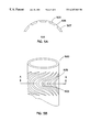
- FIG. 7 is an embodiment of the invention 700 showing an application in which microfeatures are to be introduced to a conical depression by a tool with an external conical shape for fitting therein.
- FIG. 8 is an embodiment of the invention showing a bore in a tool for forming microfeatures on an included shaft.
- FIG. 9 is an embodiment of the invention 900 in which a pattern on a flat tool has been configured in order that the pattern may be electromechanically machined on a flat surface.
- FIG. 10 is an embodiment of the invention 1000 showing a cross sectional view of the flat tool of FIG. 9 demonstrating how an insulator may be used in defining a pattern of microfeatures.
- Electrochemical machining has many advantages over the conventional mechanical machining. Material displacement, resulting in “bumps”, “spikes”, also called “kerf” in machining, which are common with mechanical machining, is avoided by electrochemical machining. ECM is also well suited to machining microfeatures, where mechanical tools may be too fragile, or if not fragile, too large. However, ECM as it was practiced in the prior art introduces other problems. One problem is that ECM has involved using an electrode to essentially “paint” microfeatures, a slow and expensive process.
- FIG. 1 a prior art embodiment of ECM 100 is illustrated in an idealized view.
- the electrode or tool for ECM 103 is shown inside a conceptual direct current (DC) circuit; where the electrode 103 is to be connected to the cathode, and the workpiece 105 , in this case a ferrous material, is illustrated in a blow up of the work area 107 .
- a salt solution plus electrical flow is being used to etch ferrous material (Fe).
- the ferrous hydroxide is discharged in a flow of the etchant.
- the hydroxyl ions which may be considered to be the conductors of the DC current, also increase, and as they attack the ferrous ions, giving up their excess electric charge in the process, they “rip” ferrous ions out of the workpiece.
- the current essentially causes the ions of the workpiece to dissolve in solution.
- FIGS. 1, 2 , 3 , 4 are embodiments of the ECM workpiece in a completed state.
- Bearing 303 having microgrooves machined therein, which are emphasized here for clarity, resides in a race 305 , with a shaft 307 being attached to bearing 303 .
- ECM might be used to provide grooves 306 inside race 305 as an alternative or in addition to grooves on bearing 303 . It is normal for either bearing 303 or race 305 to be stationary, with the other moving at high speeds, in this case rotating.
- the grooves will typically be provided on at least the one that is moving, bearing 303 or race 305 .
- the purpose of the grooves is to encourage a fluid dynamic fluid, such as air, toward the center of the bearing when the bearing is in use. Thereby a high pressure area is induced, holding bearing 303 away from race 305 with very little friction, but as much force as practical.
- bearing 303 or race 305 As the speed of the moving part, bearing 303 or race 305 , increases, it is desired that the amount of fluid dynamic fluid pressurized be minimized, since energy is used in pressurizing the fluid or gas involved. It is therefore desired that both the spacing between parts, such as the bearing 303 and race 305 , and the grooves, such as in bearing 303 , be minimized. This requires that the grooves in, for example, bearing 303 , be very shallow, and that no “kerf” or “lips” be introduced by the manufacturing thereof, meaning imperfections rising above the surface of the workpiece. The particular shape or placement of the grooves is not part of this invention, only the apparatus and method by which they are achieved.
- FIG. 4 shows a fluid dynamic bearing incorporating a shaft 10 adapted to rotate inside a bushing or sleeve 200 as shown in FIG. 2 .
- One of the two opposing surfaces, in this case the shaft carries cylindrical sections of spiral grooves.
- a thrust plate 14 rotating in a recess 309 in the sleeve or bearing race 200 , is also provided with concentric spiral groove sections 303 as shown.
- the relative rotation of the shaft and sleeve combination pumps the fluid as a function of the direction and angle of the grooves with respect to the sense of rotation of the shaft 10 and thrust plate 14 .
- the pumping action builds up multiple pressure in zones along the journal and thrust plate, maintaining a fluid film between the relatively rotating parts, and providing stiffness for the bearing.
- the grooves are of the type which are readily formed by the electrodes used in the present invention.
- the grooves must be very clean and well-formed, but with no “kerf” on the edges due to the manufacturing process. Also, since this is a common application, the manufacturing process requires high volumes with high quality of the grooved parts. This in turn requires precision tooling as is taught by the invention, and operation on as large an area of a workpiece as practical, so that the time spent on each workpiece may be minimized.
- FIGS. 5A and 5B are an embodiment of a cylindrical tool of this invention shown in perspective in FIG. 5 A and cross section in FIG. 5 B.
- grooves or slots 503 were formed between teeth 505 . It is recognized, of course, that grooves will be formed in the workpiece opposite the teeth or lands 503 .
- An insulator 507 was then provided in grooves 503 , for example, by applying a material such as epoxy or acrylic material to cover both the teeth and the intermediate slots, then polishing the outside of the tool surface. Rotating the tool 500 and applying a spaced polishing tool will cause the applied material to be removed outside the slots, but left in the slots, as shown.
- the cylindrical tool 500 has teeth 505 in the shape of a pattern of the slots or grooves to be formed on the surface of the bearing race, which in this case would be a bearing sleeve.
- the tool can be the length of all bearings to be formed on a complementary shaft or sleeve, so that all the grooves of a shaft supporting fluid dynamic bearing can be formed at once.
- the tool can also be used to form grooves for a bearing on the inner surface of a bearing sleeve.
- FIG. 6 is a partial view of an embodiment of a cylindrical tool of this invention 600 , in this case, a bore machining tool for introducing grooves into a bore hole in a workpiece.
- Raised tooth also called “kerf” might occur with the prior art methods, as shown herein at 603 .
- One method of the prior art for providing grooves, especially when an arced groove rather than the square groove of FIG. 5 is desired, is to use a hard ball under pressure against the workpiece, whereby the hard ball is made to sink into the workpiece. Since the displaced material is not removed, it “flows” outward from the ball, and some of it becomes a raised tooth or “kerf” as discussed before.
- Such kerf must be removed before the shaft could be used as an electrode; however, once the electrode can be reused many times to form corresponding grooves on multiple sleeves, the issue of key removal is dramatically simplified.
- FIG. 7 is an embodiment of the invention 700 .
- a conical tool for providing grooves for one surface of a conical bearing is disclosed.
- Conical bearings are becoming more common, especially in disc drives, as they provide both radial and lateral stability, thereby saving space. Such bearings are difficult to form in mass production machining.
- electrochemical machining approach of the present invention single or limited number of conical elements can be machined or otherwise formed according to the invention, and each used to make a large number of conical grooved surfaces.
- FIG. 7 shows such a male cone 700 , with lands or raised segments 702 corresponding to the groove pattern desired to be etched on a female cone.
- FIG. 8 is an embodiment of the invention comprising a perspective view of a sleeve 803 having features 805 on the interior surface corresponding to the grooves to be formed on the surface of a shaft for a fluid dynamic bearing such as shown above.
- a cylindrical tool 803 for providing grooves on a shaft or rod introduced into a bore in tool 803 using the pattern 805 is shown.
- FIG. 9 is an embodiment of the invention 900 where a pattern in accordance with the invention is shown on a flat tool surface 902 .
- the lands 904 are defined so that a groove pattern such as on a thrust plate shown above can be established.
- FIG. 10 is an embodiment of the invention 1000 illustrating how the tool of FIG. 9 is prepared.
- the tool conductive part is left flat, and an insulating layer 906 is adhered to the tool surface and patterned as shown.
- a metal electrode 1003 forming a tool conductive part has a pattern defined by a patterned insulator 1005 on the surface. Thereby no machining of the metal of the tool is required.
Abstract
Description
Claims (13)
Priority Applications (3)
| Application Number | Priority Date | Filing Date | Title |
|---|---|---|---|
| US09/326,443 US6267869B1 (en) | 1998-06-04 | 1999-06-04 | Electrode design for electrochemical machining of grooves |
| US09/441,153 US6251257B1 (en) | 1999-01-29 | 1999-11-12 | Apparatus and method for electrochemically etching grooves in an outer surface of a shaft |
| US09/919,746 US6638414B2 (en) | 1998-06-04 | 2001-07-31 | Electrode design for electrochemical machining of grooves |
Applications Claiming Priority (2)
| Application Number | Priority Date | Filing Date | Title |
|---|---|---|---|
| US8812698P | 1998-06-04 | 1998-06-04 | |
| US09/326,443 US6267869B1 (en) | 1998-06-04 | 1999-06-04 | Electrode design for electrochemical machining of grooves |
Related Child Applications (2)
| Application Number | Title | Priority Date | Filing Date |
|---|---|---|---|
| US09/441,153 Continuation-In-Part US6251257B1 (en) | 1999-01-29 | 1999-11-12 | Apparatus and method for electrochemically etching grooves in an outer surface of a shaft |
| US09/919,746 Continuation US6638414B2 (en) | 1998-06-04 | 2001-07-31 | Electrode design for electrochemical machining of grooves |
Publications (1)
| Publication Number | Publication Date |
|---|---|
| US6267869B1 true US6267869B1 (en) | 2001-07-31 |
Family
ID=26778310
Family Applications (2)
| Application Number | Title | Priority Date | Filing Date |
|---|---|---|---|
| US09/326,443 Expired - Lifetime US6267869B1 (en) | 1998-06-04 | 1999-06-04 | Electrode design for electrochemical machining of grooves |
| US09/919,746 Expired - Lifetime US6638414B2 (en) | 1998-06-04 | 2001-07-31 | Electrode design for electrochemical machining of grooves |
Family Applications After (1)
| Application Number | Title | Priority Date | Filing Date |
|---|---|---|---|
| US09/919,746 Expired - Lifetime US6638414B2 (en) | 1998-06-04 | 2001-07-31 | Electrode design for electrochemical machining of grooves |
Country Status (1)
| Country | Link |
|---|---|
| US (2) | US6267869B1 (en) |
Cited By (21)
| Publication number | Priority date | Publication date | Assignee | Title |
|---|---|---|---|---|
| WO2002042030A2 (en) * | 2000-11-27 | 2002-05-30 | Lehr Precision Inc. | Fluted electrochemical machining |
| US20020134683A1 (en) * | 2001-03-09 | 2002-09-26 | Steele Mark G. | Counter plate electrode with self adjusting z-axis |
| WO2003068440A1 (en) * | 2002-02-15 | 2003-08-21 | Minebea Co., Ltd. | Method for manufacturing an electrode for the electrochemical machining of a workpiece and an electrode manufactured according to this method |
| US20030221959A1 (en) * | 2002-05-28 | 2003-12-04 | Cochran Dustin Alan | Method and apparatus for forming grooved journals |
| US20030221973A1 (en) * | 2002-05-28 | 2003-12-04 | Gunter Heine | Method and apparatus for electrochemical machining of grooves for a hydrodynamic bearing |
| US20030223660A1 (en) * | 2002-06-03 | 2003-12-04 | Grantz Alan Lyndon | Rotating shaft conical fluid dynamic bearing |
| US20040005101A1 (en) * | 2002-07-01 | 2004-01-08 | Grantz Alan Lyndon | Non-recirculating conical fluid dynamic bearing for an electric motor |
| US6764590B1 (en) * | 2001-11-08 | 2004-07-20 | Seagate Technology Llc | Automated machine control gap for conical fluid dynamic bearing ECM grooving |
| US20040140223A1 (en) * | 2003-01-21 | 2004-07-22 | Cochran Dustin A. | System and method for radially positioning a workpiece for electrochemical machining |
| US6767438B2 (en) * | 2000-06-02 | 2004-07-27 | Seagate Technology Llc | Dual voltage conical ECM electrode |
| DE10237324B4 (en) * | 2002-02-15 | 2006-02-09 | Minebea Co., Ltd. | A method of manufacturing an electrode for the electrochemical machining of a workpiece and an electrode produced by the method |
| WO2006033758A2 (en) * | 2004-09-17 | 2006-03-30 | Minebea Co., Ltd. | Electrochemical machining tool and method for machining a product using the same |
| WO2006093605A1 (en) * | 2005-03-02 | 2006-09-08 | Minebea Co., Ltd. | Electrode tool and method for electrochemical machining |
| DE102006044416A1 (en) * | 2006-09-18 | 2008-03-27 | Siemens Ag | Process for the electrochemical coating or stripping of components |
| US20100272888A1 (en) * | 2006-08-08 | 2010-10-28 | Siemens Aktiengesellschaft | Method for producing a wear layer |
| TWI384096B (en) * | 2008-11-04 | 2013-02-01 | Metal Ind Res & Dev Ct | Electrochemical process of the processing electrode, the preparation method and manufacturing equipment |
| CN103273152A (en) * | 2013-06-09 | 2013-09-04 | 常州工学院 | Cathode for numerical control electrochemical machining machine tool drilling |
| US9263224B2 (en) | 2013-05-31 | 2016-02-16 | General Electric Company | Liquid bearing assembly and method of constructing same |
| US20170237103A1 (en) * | 2014-11-18 | 2017-08-17 | Lg Chem, Ltd. | Method for manufacturing solid oxide fuel cell |
| TWI615225B (en) * | 2016-12-12 | 2018-02-21 | 財團法人金屬工業研究發展中心 | Electrochemical processing device |
| US9976227B2 (en) | 2014-05-15 | 2018-05-22 | Baker Hughes, A Ge Company, Llc | Electrochemical machining method for rotors or stators for moineau pumps |
Families Citing this family (10)
| Publication number | Priority date | Publication date | Assignee | Title |
|---|---|---|---|---|
| JP3614749B2 (en) * | 2000-03-13 | 2005-01-26 | 光洋精工株式会社 | Hydrodynamic groove processing method for hydrodynamic bearings |
| CN1989276A (en) * | 2004-01-23 | 2007-06-27 | 美蓓亚株式会社 | Electrode tool for electrochemical machining and method for manufacturing same |
| DE102005022236A1 (en) * | 2005-05-13 | 2006-11-16 | Mtu Aero Engines Gmbh | Heat transfer reactor metal foils manufacture involves electrochemical machining process for generating microstructures in metal foils |
| US7625468B2 (en) * | 2006-03-15 | 2009-12-01 | Seagate Technology, Llc | Electrode for electrochemical machining |
| US20070217076A1 (en) * | 2006-03-15 | 2007-09-20 | Seagate Technology Llc | Nanoscale machined electrode and workpiece, and method of making the same |
| US8329021B2 (en) * | 2010-10-28 | 2012-12-11 | Palmaz Scientific, Inc. | Method for mass transfer of micro-patterns onto medical devices |
| US8524068B2 (en) * | 2011-08-30 | 2013-09-03 | Western Digital (Fremont), Llc | Low-rate electrochemical etch of thin film metals and alloys |
| DE102011122523A1 (en) * | 2011-12-29 | 2013-07-04 | Minebea Co., Ltd. | Electrochemical machining electrode for producing groove structures for e.g. fluid dynamic radial bearing of spindle motor for hard disk drive, has electrically insulating component arranged between two electrically conductive components |
| JP6071742B2 (en) | 2013-05-16 | 2017-02-01 | 三菱重工業株式会社 | Electrolytic machining tool, electrolytic machining system, and method for manufacturing perforated member |
| AT515035B1 (en) * | 2013-11-11 | 2019-06-15 | Minebea Mitsumi Inc | Electrode for the electrochemical machining of a metallic workpiece |
Citations (1)
| Publication number | Priority date | Publication date | Assignee | Title |
|---|---|---|---|---|
| US5863412A (en) * | 1995-10-17 | 1999-01-26 | Canon Kabushiki Kaisha | Etching method and process for producing a semiconductor element using said etching method |
Family Cites Families (1)
| Publication number | Priority date | Publication date | Assignee | Title |
|---|---|---|---|---|
| US4690737A (en) * | 1986-06-10 | 1987-09-01 | Cation Corporation | Electrochemical rifling of gun barrels |
-
1999
- 1999-06-04 US US09/326,443 patent/US6267869B1/en not_active Expired - Lifetime
-
2001
- 2001-07-31 US US09/919,746 patent/US6638414B2/en not_active Expired - Lifetime
Patent Citations (1)
| Publication number | Priority date | Publication date | Assignee | Title |
|---|---|---|---|---|
| US5863412A (en) * | 1995-10-17 | 1999-01-26 | Canon Kabushiki Kaisha | Etching method and process for producing a semiconductor element using said etching method |
Cited By (36)
| Publication number | Priority date | Publication date | Assignee | Title |
|---|---|---|---|---|
| US6767438B2 (en) * | 2000-06-02 | 2004-07-27 | Seagate Technology Llc | Dual voltage conical ECM electrode |
| US6413407B1 (en) * | 2000-11-27 | 2002-07-02 | Lehr Precision, Inc. | Fluted electrochemical machining |
| WO2002042030A3 (en) * | 2000-11-27 | 2002-07-25 | Lehr Prec Inc | Fluted electrochemical machining |
| WO2002042030A2 (en) * | 2000-11-27 | 2002-05-30 | Lehr Precision Inc. | Fluted electrochemical machining |
| US20020134683A1 (en) * | 2001-03-09 | 2002-09-26 | Steele Mark G. | Counter plate electrode with self adjusting z-axis |
| US6884330B2 (en) * | 2001-03-09 | 2005-04-26 | Seagate Technology Llc | Counter plate electrode with self adjusting z-axis |
| US6764590B1 (en) * | 2001-11-08 | 2004-07-20 | Seagate Technology Llc | Automated machine control gap for conical fluid dynamic bearing ECM grooving |
| US20050082173A1 (en) * | 2002-02-15 | 2005-04-21 | Jurgen Oelsch | Method for manufacturing an electrode for the electrochemical machining of a workpiece and an electrode manufactured according to this method |
| DE10237324B4 (en) * | 2002-02-15 | 2006-02-09 | Minebea Co., Ltd. | A method of manufacturing an electrode for the electrochemical machining of a workpiece and an electrode produced by the method |
| WO2003068440A1 (en) * | 2002-02-15 | 2003-08-21 | Minebea Co., Ltd. | Method for manufacturing an electrode for the electrochemical machining of a workpiece and an electrode manufactured according to this method |
| US20030221973A1 (en) * | 2002-05-28 | 2003-12-04 | Gunter Heine | Method and apparatus for electrochemical machining of grooves for a hydrodynamic bearing |
| US20030221959A1 (en) * | 2002-05-28 | 2003-12-04 | Cochran Dustin Alan | Method and apparatus for forming grooved journals |
| US7235168B2 (en) | 2002-05-28 | 2007-06-26 | Seagate Technology. Llc | Method for electrochemically forming a hydrodynamic bearing surface |
| US20030223660A1 (en) * | 2002-06-03 | 2003-12-04 | Grantz Alan Lyndon | Rotating shaft conical fluid dynamic bearing |
| US7101085B2 (en) | 2002-06-03 | 2006-09-05 | Seagate Technology Llc | Rotating shaft conical fluid dynamic bearing |
| US20040005101A1 (en) * | 2002-07-01 | 2004-01-08 | Grantz Alan Lyndon | Non-recirculating conical fluid dynamic bearing for an electric motor |
| US7213972B2 (en) | 2002-07-01 | 2007-05-08 | Seagate Technology Llc | Non-recirculating conical fluid dynamic bearing for an electric motor |
| US20040140223A1 (en) * | 2003-01-21 | 2004-07-22 | Cochran Dustin A. | System and method for radially positioning a workpiece for electrochemical machining |
| US7344623B2 (en) * | 2003-01-21 | 2008-03-18 | Seagate Technology Llc | System and method for radially positioning a workpiece for electrochemical machining |
| WO2006033758A3 (en) * | 2004-09-17 | 2007-01-11 | Minebea Co Ltd | Electrochemical machining tool and method for machining a product using the same |
| WO2006033758A2 (en) * | 2004-09-17 | 2006-03-30 | Minebea Co., Ltd. | Electrochemical machining tool and method for machining a product using the same |
| WO2006093605A1 (en) * | 2005-03-02 | 2006-09-08 | Minebea Co., Ltd. | Electrode tool and method for electrochemical machining |
| US8673405B2 (en) | 2006-08-08 | 2014-03-18 | Siemens Aktiengesellschaft | Method for producing a wear layer |
| US20100272888A1 (en) * | 2006-08-08 | 2010-10-28 | Siemens Aktiengesellschaft | Method for producing a wear layer |
| DE102006044416A1 (en) * | 2006-09-18 | 2008-03-27 | Siemens Ag | Process for the electrochemical coating or stripping of components |
| US20100072073A1 (en) * | 2006-09-18 | 2010-03-25 | Rene Jabado | Method for the electrochemically coating or stripping the coating from components |
| TWI384096B (en) * | 2008-11-04 | 2013-02-01 | Metal Ind Res & Dev Ct | Electrochemical process of the processing electrode, the preparation method and manufacturing equipment |
| US9263224B2 (en) | 2013-05-31 | 2016-02-16 | General Electric Company | Liquid bearing assembly and method of constructing same |
| CN103273152A (en) * | 2013-06-09 | 2013-09-04 | 常州工学院 | Cathode for numerical control electrochemical machining machine tool drilling |
| CN103273152B (en) * | 2013-06-09 | 2016-03-09 | 常州工学院 | The boring negative electrode of a kind of numerical control electrolytic machine tool |
| US9976227B2 (en) | 2014-05-15 | 2018-05-22 | Baker Hughes, A Ge Company, Llc | Electrochemical machining method for rotors or stators for moineau pumps |
| US20170237103A1 (en) * | 2014-11-18 | 2017-08-17 | Lg Chem, Ltd. | Method for manufacturing solid oxide fuel cell |
| CN107078328A (en) * | 2014-11-18 | 2017-08-18 | 株式会社Lg化学 | Method for manufacturing SOFC |
| US10431841B2 (en) * | 2014-11-18 | 2019-10-01 | Lg Chem, Ltd. | Method for manufacturing solid oxide fuel cell |
| CN107078328B (en) * | 2014-11-18 | 2021-05-04 | 株式会社Lg化学 | Method for manufacturing solid oxide fuel cell |
| TWI615225B (en) * | 2016-12-12 | 2018-02-21 | 財團法人金屬工業研究發展中心 | Electrochemical processing device |
Also Published As
| Publication number | Publication date |
|---|---|
| US20010050235A1 (en) | 2001-12-13 |
| US6638414B2 (en) | 2003-10-28 |
Similar Documents
| Publication | Publication Date | Title |
|---|---|---|
| US6267869B1 (en) | Electrode design for electrochemical machining of grooves | |
| US6698097B1 (en) | Method for manufacturing a tool that is used to form dynamic pressure generating grooves in dynamic pressure bearing devices | |
| US6896143B2 (en) | Electrolytic machining method, method for manufacturing dynamic pressure bearing devices, and dynamic pressure bearing devices manufactured according to the manufacturing method | |
| JP2006239803A (en) | Electrochemical machining electrode tool tool and manufacturing method for it | |
| EP1474259B1 (en) | Method for manufacturing an electrode for electrochemical machining of a workpiece and an electrode manufactured according to this method | |
| US6251257B1 (en) | Apparatus and method for electrochemically etching grooves in an outer surface of a shaft | |
| US7625468B2 (en) | Electrode for electrochemical machining | |
| EP1068921A1 (en) | Device for electrolytically machining microgrooves on internal surface of aerodynamic bearing housing | |
| US6358394B1 (en) | Apparatus and method for manufacturing fluid dynamic bearings | |
| US4711706A (en) | Method of producing groove/land patterns for dynamic bearings | |
| JP2002039166A (en) | Dynamic pressure type thrust bearing device and its manufacturing method | |
| US7235168B2 (en) | Method for electrochemically forming a hydrodynamic bearing surface | |
| JP5467709B2 (en) | Nanoscale processed electrode and processed product, and manufacturing method thereof | |
| US6884330B2 (en) | Counter plate electrode with self adjusting z-axis | |
| TWI384096B (en) | Electrochemical process of the processing electrode, the preparation method and manufacturing equipment | |
| JP4630540B2 (en) | Nozzle plate manufacturing method | |
| JPS63102835A (en) | Electrode for electric discharge machining | |
| JP2003191133A (en) | Electrochemical machining electrode for dynamic pressure groove and method for machining dynamic pressure groove using it | |
| TW533282B (en) | Etching method for manufacturing fluid bearing | |
| JP4298381B2 (en) | Manufacturing method of rotating structural parts | |
| KR100213925B1 (en) | Method for forming hydrodynamic groove on fluid bearing | |
| JP2003074556A (en) | Manufacturing method of dynamic pressure bearing device | |
| JP3842415B2 (en) | Core rod for forming bearing surface of hydrodynamic porous oil-impregnated bearing | |
| JP2009138238A (en) | Method for forming groove for generating dynamic pressure, and apparatus therefor | |
| JP2002219603A (en) | Groove working device for fluid bearing |
Legal Events
| Date | Code | Title | Description |
|---|---|---|---|
| AS | Assignment |
Owner name: SEAGATE TECHNOLOGY, INC., CALIFORNIA Free format text: ASSIGNMENT OF ASSIGNORS INTEREST;ASSIGNORS:MACLEOD, DONALD J.;KLOEPPEL, KLAUS D.;CLARK, WESLEY R.;AND OTHERS;REEL/FRAME:010186/0508;SIGNING DATES FROM 19990730 TO 19990802 |
|
| AS | Assignment |
Owner name: SEAGATE TECHNOLOGY LLC, CALIFORNIA Free format text: ASSIGNMENT OF ASSIGNORS INTEREST;ASSIGNOR:SEAGATE TECHNOLGOY, INC.;REEL/FRAME:010985/0436 Effective date: 20000628 |
|
| STCF | Information on status: patent grant |
Free format text: PATENTED CASE |
|
| AS | Assignment |
Owner name: JPMORGAN CHASE BANK, AS COLLATERAL AGENT, NEW YORK Free format text: SECURITY AGREEMENT;ASSIGNOR:SEAGATE TECHNOLOGY LLC;REEL/FRAME:013177/0001 Effective date: 20020513 Owner name: JPMORGAN CHASE BANK, AS COLLATERAL AGENT,NEW YORK Free format text: SECURITY AGREEMENT;ASSIGNOR:SEAGATE TECHNOLOGY LLC;REEL/FRAME:013177/0001 Effective date: 20020513 |
|
| FPAY | Fee payment |
Year of fee payment: 4 |
|
| AS | Assignment |
Owner name: SEAGATE TECHNOLOGY LLC, CALIFORNIA Free format text: RELEASE OF SECURITY INTERESTS IN PATENT RIGHTS;ASSIGNOR:JPMORGAN CHASE BANK, N.A. (FORMERLY KNOWN AS THE CHASE MANHATTAN BANK AND JPMORGAN CHASE BANK), AS ADMINISTRATIVE AGENT;REEL/FRAME:016945/0775 Effective date: 20051130 |
|
| FPAY | Fee payment |
Year of fee payment: 8 |
|
| AS | Assignment |
Owner name: JPMORGAN CHASE BANK, N.A., AS ADMINISTRATIVE AGENT Free format text: SECURITY AGREEMENT;ASSIGNORS:MAXTOR CORPORATION;SEAGATE TECHNOLOGY LLC;SEAGATE TECHNOLOGY INTERNATIONAL;REEL/FRAME:022757/0017 Effective date: 20090507 Owner name: WELLS FARGO BANK, NATIONAL ASSOCIATION, AS COLLATE Free format text: SECURITY AGREEMENT;ASSIGNORS:MAXTOR CORPORATION;SEAGATE TECHNOLOGY LLC;SEAGATE TECHNOLOGY INTERNATIONAL;REEL/FRAME:022757/0017 Effective date: 20090507 |
|
| AS | Assignment |
Owner name: SEAGATE TECHNOLOGY INTERNATIONAL, CALIFORNIA Free format text: RELEASE;ASSIGNOR:JPMORGAN CHASE BANK, N.A., AS ADMINISTRATIVE AGENT;REEL/FRAME:025662/0001 Effective date: 20110114 Owner name: MAXTOR CORPORATION, CALIFORNIA Free format text: RELEASE;ASSIGNOR:JPMORGAN CHASE BANK, N.A., AS ADMINISTRATIVE AGENT;REEL/FRAME:025662/0001 Effective date: 20110114 Owner name: SEAGATE TECHNOLOGY LLC, CALIFORNIA Free format text: RELEASE;ASSIGNOR:JPMORGAN CHASE BANK, N.A., AS ADMINISTRATIVE AGENT;REEL/FRAME:025662/0001 Effective date: 20110114 Owner name: SEAGATE TECHNOLOGY HDD HOLDINGS, CALIFORNIA Free format text: RELEASE;ASSIGNOR:JPMORGAN CHASE BANK, N.A., AS ADMINISTRATIVE AGENT;REEL/FRAME:025662/0001 Effective date: 20110114 |
|
| AS | Assignment |
Owner name: THE BANK OF NOVA SCOTIA, AS ADMINISTRATIVE AGENT, Free format text: SECURITY AGREEMENT;ASSIGNOR:SEAGATE TECHNOLOGY LLC;REEL/FRAME:026010/0350 Effective date: 20110118 |
|
| FPAY | Fee payment |
Year of fee payment: 12 |
|
| AS | Assignment |
Owner name: SEAGATE TECHNOLOGY LLC, CALIFORNIA Free format text: TERMINATION AND RELEASE OF SECURITY INTEREST IN PATENT RIGHTS;ASSIGNOR:WELLS FARGO BANK, NATIONAL ASSOCIATION, AS COLLATERAL AGENT AND SECOND PRIORITY REPRESENTATIVE;REEL/FRAME:030833/0001 Effective date: 20130312 Owner name: SEAGATE TECHNOLOGY US HOLDINGS, INC., CALIFORNIA Free format text: TERMINATION AND RELEASE OF SECURITY INTEREST IN PATENT RIGHTS;ASSIGNOR:WELLS FARGO BANK, NATIONAL ASSOCIATION, AS COLLATERAL AGENT AND SECOND PRIORITY REPRESENTATIVE;REEL/FRAME:030833/0001 Effective date: 20130312 Owner name: SEAGATE TECHNOLOGY INTERNATIONAL, CAYMAN ISLANDS Free format text: TERMINATION AND RELEASE OF SECURITY INTEREST IN PATENT RIGHTS;ASSIGNOR:WELLS FARGO BANK, NATIONAL ASSOCIATION, AS COLLATERAL AGENT AND SECOND PRIORITY REPRESENTATIVE;REEL/FRAME:030833/0001 Effective date: 20130312 Owner name: EVAULT INC. (F/K/A I365 INC.), CALIFORNIA Free format text: TERMINATION AND RELEASE OF SECURITY INTEREST IN PATENT RIGHTS;ASSIGNOR:WELLS FARGO BANK, NATIONAL ASSOCIATION, AS COLLATERAL AGENT AND SECOND PRIORITY REPRESENTATIVE;REEL/FRAME:030833/0001 Effective date: 20130312 |