WO2014178293A1 - 光ファイバ母材の製造方法、及び光ファイバの製造方法 - Google Patents
光ファイバ母材の製造方法、及び光ファイバの製造方法 Download PDFInfo
- Publication number
- WO2014178293A1 WO2014178293A1 PCT/JP2014/061089 JP2014061089W WO2014178293A1 WO 2014178293 A1 WO2014178293 A1 WO 2014178293A1 JP 2014061089 W JP2014061089 W JP 2014061089W WO 2014178293 A1 WO2014178293 A1 WO 2014178293A1
- Authority
- WO
- WIPO (PCT)
- Prior art keywords
- base material
- glass
- core
- clad
- optical fiber
- Prior art date
- Legal status (The legal status is an assumption and is not a legal conclusion. Google has not performed a legal analysis and makes no representation as to the accuracy of the status listed.)
- Ceased
Links
Images









Classifications
-
- C—CHEMISTRY; METALLURGY
- C03—GLASS; MINERAL OR SLAG WOOL
- C03B—MANUFACTURE, SHAPING, OR SUPPLEMENTARY PROCESSES
- C03B37/00—Manufacture or treatment of flakes, fibres, or filaments from softened glass, minerals, or slags
- C03B37/01—Manufacture of glass fibres or filaments
- C03B37/012—Manufacture of preforms for drawing fibres or filaments
- C03B37/01205—Manufacture of preforms for drawing fibres or filaments starting from tubes, rods, fibres or filaments
- C03B37/01211—Manufacture of preforms for drawing fibres or filaments starting from tubes, rods, fibres or filaments by inserting one or more rods or tubes into a tube
- C03B37/01222—Manufacture of preforms for drawing fibres or filaments starting from tubes, rods, fibres or filaments by inserting one or more rods or tubes into a tube for making preforms of multiple core optical fibres
-
- C—CHEMISTRY; METALLURGY
- C03—GLASS; MINERAL OR SLAG WOOL
- C03B—MANUFACTURE, SHAPING, OR SUPPLEMENTARY PROCESSES
- C03B37/00—Manufacture or treatment of flakes, fibres, or filaments from softened glass, minerals, or slags
- C03B37/01—Manufacture of glass fibres or filaments
- C03B37/012—Manufacture of preforms for drawing fibres or filaments
- C03B37/01205—Manufacture of preforms for drawing fibres or filaments starting from tubes, rods, fibres or filaments
-
- C—CHEMISTRY; METALLURGY
- C03—GLASS; MINERAL OR SLAG WOOL
- C03B—MANUFACTURE, SHAPING, OR SUPPLEMENTARY PROCESSES
- C03B37/00—Manufacture or treatment of flakes, fibres, or filaments from softened glass, minerals, or slags
- C03B37/01—Manufacture of glass fibres or filaments
- C03B37/012—Manufacture of preforms for drawing fibres or filaments
- C03B37/01205—Manufacture of preforms for drawing fibres or filaments starting from tubes, rods, fibres or filaments
- C03B37/01225—Means for changing or stabilising the shape, e.g. diameter, of tubes or rods in general, e.g. collapsing
- C03B37/01228—Removal of preform material
- C03B37/01234—Removal of preform material to form longitudinal grooves, e.g. by chamfering
-
- C—CHEMISTRY; METALLURGY
- C03—GLASS; MINERAL OR SLAG WOOL
- C03B—MANUFACTURE, SHAPING, OR SUPPLEMENTARY PROCESSES
- C03B37/00—Manufacture or treatment of flakes, fibres, or filaments from softened glass, minerals, or slags
- C03B37/01—Manufacture of glass fibres or filaments
- C03B37/012—Manufacture of preforms for drawing fibres or filaments
- C03B37/014—Manufacture of preforms for drawing fibres or filaments made entirely or partially by chemical means, e.g. vapour phase deposition of bulk porous glass either by outside vapour deposition [OVD], or by outside vapour phase oxidation [OVPO] or by vapour axial deposition [VAD]
- C03B37/01486—Means for supporting, rotating or translating the preforms being formed, e.g. lathes
-
- C—CHEMISTRY; METALLURGY
- C03—GLASS; MINERAL OR SLAG WOOL
- C03B—MANUFACTURE, SHAPING, OR SUPPLEMENTARY PROCESSES
- C03B37/00—Manufacture or treatment of flakes, fibres, or filaments from softened glass, minerals, or slags
- C03B37/01—Manufacture of glass fibres or filaments
- C03B37/012—Manufacture of preforms for drawing fibres or filaments
- C03B37/014—Manufacture of preforms for drawing fibres or filaments made entirely or partially by chemical means, e.g. vapour phase deposition of bulk porous glass either by outside vapour deposition [OVD], or by outside vapour phase oxidation [OVPO] or by vapour axial deposition [VAD]
- C03B37/01486—Means for supporting, rotating or translating the preforms being formed, e.g. lathes
- C03B37/01493—Deposition substrates, e.g. targets, mandrels, start rods or tubes
-
- C—CHEMISTRY; METALLURGY
- C03—GLASS; MINERAL OR SLAG WOOL
- C03B—MANUFACTURE, SHAPING, OR SUPPLEMENTARY PROCESSES
- C03B37/00—Manufacture or treatment of flakes, fibres, or filaments from softened glass, minerals, or slags
- C03B37/01—Manufacture of glass fibres or filaments
- C03B37/012—Manufacture of preforms for drawing fibres or filaments
- C03B37/014—Manufacture of preforms for drawing fibres or filaments made entirely or partially by chemical means, e.g. vapour phase deposition of bulk porous glass either by outside vapour deposition [OVD], or by outside vapour phase oxidation [OVPO] or by vapour axial deposition [VAD]
- C03B37/018—Manufacture of preforms for drawing fibres or filaments made entirely or partially by chemical means, e.g. vapour phase deposition of bulk porous glass either by outside vapour deposition [OVD], or by outside vapour phase oxidation [OVPO] or by vapour axial deposition [VAD] by glass deposition on a glass substrate, e.g. by inside-, modified-, plasma- or plasma modified- chemical vapour deposition [ICVD, MCVD, PCVD, PMCVD], i.e. by thin layer coating on the inside or outside of a glass tube or on a glass rod
-
- C—CHEMISTRY; METALLURGY
- C03—GLASS; MINERAL OR SLAG WOOL
- C03B—MANUFACTURE, SHAPING, OR SUPPLEMENTARY PROCESSES
- C03B37/00—Manufacture or treatment of flakes, fibres, or filaments from softened glass, minerals, or slags
- C03B37/01—Manufacture of glass fibres or filaments
- C03B37/02—Manufacture of glass fibres or filaments by drawing or extruding, e.g. direct drawing of molten glass from nozzles; Cooling fins therefor
- C03B37/025—Manufacture of glass fibres or filaments by drawing or extruding, e.g. direct drawing of molten glass from nozzles; Cooling fins therefor from reheated softened tubes, rods, fibres or filaments, e.g. drawing fibres from preforms
- C03B37/027—Fibres composed of different sorts of glass, e.g. glass optical fibres
-
- G—PHYSICS
- G02—OPTICS
- G02B—OPTICAL ELEMENTS, SYSTEMS OR APPARATUS
- G02B6/00—Light guides; Structural details of arrangements comprising light guides and other optical elements, e.g. couplings
- G02B6/02—Optical fibres with cladding with or without a coating
- G02B6/02042—Multicore optical fibres
-
- C—CHEMISTRY; METALLURGY
- C03—GLASS; MINERAL OR SLAG WOOL
- C03B—MANUFACTURE, SHAPING, OR SUPPLEMENTARY PROCESSES
- C03B2203/00—Fibre product details, e.g. structure, shape
- C03B2203/10—Internal structure or shape details
- C03B2203/22—Radial profile of refractive index, composition or softening point
- C03B2203/23—Double or multiple optical cladding profiles
-
- C—CHEMISTRY; METALLURGY
- C03—GLASS; MINERAL OR SLAG WOOL
- C03B—MANUFACTURE, SHAPING, OR SUPPLEMENTARY PROCESSES
- C03B2203/00—Fibre product details, e.g. structure, shape
- C03B2203/34—Plural core other than bundles, e.g. double core
-
- C—CHEMISTRY; METALLURGY
- C03—GLASS; MINERAL OR SLAG WOOL
- C03B—MANUFACTURE, SHAPING, OR SUPPLEMENTARY PROCESSES
- C03B2207/00—Glass deposition burners
- C03B2207/50—Multiple burner arrangements
Definitions
- the present invention relates to an optical fiber preform manufacturing method and an optical fiber manufacturing method.
- Multi-core fiber (Multi-Core Fiber: MCF) is an optical fiber having a plurality of cores in one optical fiber, and is a new type of optical fiber in which many core parts can be provided in a space-saving manner. This multi-core fiber is expected to realize new light propagation such as large-capacity image transmission and spatial multiplexing transmission.
- Examples of the manufacturing method of the multi-core fiber include a stack & draw method and a drill method.
- a glass rod for forming a clad having a refractive index lower than that of the core is arranged around a glass rod (core base material) for forming a core, and these are made of a glass jacket tube.
- an optical fiber preform is formed by heating and stretching the material inserted into the interior of the glass (see, for example, Patent Document 1).
- the drill method is to form a hole (through hole) in a rod-shaped base material made of glass with a drill, and insert a glass rod (core base material) to form a core in this hole, An optical fiber preform is formed (see, for example, Patent Document 2).
- Patent Document 3 a plurality of core base materials for forming a core are arranged at predetermined positions, and glass fine particles are deposited from the outside of these core base materials to form a porous layer serving as a cladding. Subsequently, a method for manufacturing a multi-core fiber preform is disclosed in which a multi-core fiber preform is obtained by further sintering.
- the present invention has been made in view of the above, and provides a manufacturing method of a multi-core fiber preform capable of manufacturing a high-quality optical fiber preform at low cost, and an optical fiber manufacturing method using the same.
- the purpose is to do.
- a method for producing a multi-core fiber preform of the present invention includes a plurality of glass preforms and a first cladding portion disposed between the plurality of glass preforms.
- the step of disposing the raw material gas and the combustion gas from the burner generates glass fine particles, the first base material and the burner are moved relative to each other in the longitudinal direction of the first clad portion, and the first clad portion
- the glass fine particles are deposited on the substrate.
- one aspect of the method for producing a multi-core fiber preform of the present invention is characterized in that the first clad portion is arranged so that a cross section of the first preform approaches a circular shape.
- the first preform preparation step includes a center glass preform arrangement in which a center glass preform that is one of the plurality of glass preforms is disposed.
- a first clad portion disposing step is provided in which a center glass preform that is one of the plurality of glass preforms is disposed.
- the central glass in the first clad portion disposing step, is rotated while rotating the plurality of glass preforms around a central axis of each glass preform.
- the glass fine particles are deposited on a base material.
- the first preform preparation step is a glass rod placement step in which a glass rod is placed in a gap between the plurality of adjacent glass preforms. It is characterized by having.
- the first preform preparation step includes a center glass preform arrangement in which a center glass preform that is one of the plurality of glass preforms is disposed. And a step of ejecting the raw material gas and the combustion gas from the burner to generate glass fine particles, and moving the disposed central glass base material and the burner relative to each other in the longitudinal direction of the central glass base material.
- a recess extending in the longitudinal direction of the first preform is formed on the outer periphery of the first clad after the first clad placement step.
- the first cladding portion is a columnar member in which a recess extending in the longitudinal direction of the first preform is formed.
- the base material preparing step includes a glass base material disposing step of disposing the glass base material at a position corresponding to the concave portion.
- one aspect of the method for producing a multi-core fiber preform of the present invention is characterized in that the first clad portion is made of a powder molded body.
- one aspect of the method for producing a multi-core fiber preform of the present invention is characterized in that the first clad portion is made of glass.
- one aspect of the method for producing a multi-core fiber preform of the present invention is characterized in that the first clad portion is made of semi-sintered glass.
- At least one glass preform is arranged on the outer periphery of the second clad portion.
- a base material disposing step, and raw material gas and combustion gas are ejected from the burner to generate glass fine particles, and the disposed second clad part and the burner are moved relative to each other in the longitudinal direction of the plurality of glass base materials.
- the optical fiber manufacturing method of the present invention is characterized in that the optical fiber preform manufactured by the above-described optical fiber preform manufacturing method is drawn.
- the generation of voids in the clad can be eliminated and the core position accuracy can be increased, so that a good quality multi-core fiber preform and multi-core fiber can be manufactured at low cost.
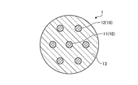
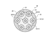
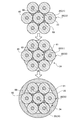
- FIG. 1 is a cross-sectional view of a multi-core fiber preform manufactured by the method for manufacturing a multi-core fiber preform according to the first embodiment of the present invention.
- FIG. 2 is a flowchart of the method for manufacturing a multi-core fiber preform according to the first embodiment of the present invention.
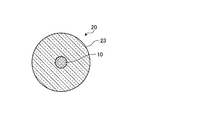
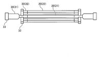
- FIG. 3A is a schematic explanatory view showing a cross section of a core preform used in the method for producing a multi-core fiber preform according to the first embodiment of the present invention.
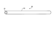
- FIG. 3B is a schematic explanatory view showing the entire core preform used in the method for producing a multi-core fiber preform according to the first embodiment of the present invention.
- FIG. 1 is a cross-sectional view of a multi-core fiber preform manufactured by the method for manufacturing a multi-core fiber preform according to the first embodiment of the present invention.
- FIG. 2 is a flowchart of the method for manufacturing a multi-core fiber preform according to the first embodiment of the present invention.
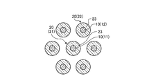
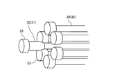
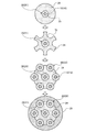
- FIG. 4A is a schematic explanatory diagram of the first core base material disposing step, and is a cross-sectional view showing the disposition of a plurality of core base materials.
- FIG. 4B is a schematic explanatory view of a first core base material disposing step, and is a schematic explanatory view showing an arrangement of a plurality of core base materials.
- FIG. 4C is a schematic explanatory view showing a dummy base material and a gripping tool.
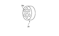
- FIG. 4D is a schematic explanatory diagram showing a spacer.
- FIG. 5A is a schematic explanatory diagram of a first clad portion disposing step.
- FIG. 5B is a schematic explanatory diagram of the first clad portion disposing step.
- FIG. 5A is a schematic explanatory diagram of a first clad portion disposing step.
- FIG. 6 is a schematic explanatory diagram of the second clad portion arranging step.
- FIG. 7 is a schematic explanatory diagram of the second clad portion disposing step.
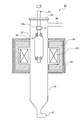
- FIG. 8 is a schematic explanatory diagram of an electric furnace used in the dehydration process and the sintering process.
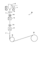
- FIG. 9 is a schematic explanatory diagram of a drawing apparatus used in the drawing process.
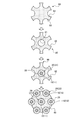
- FIG. 10 is a cross-sectional view of a multi-core fiber preform having a marker.
- FIG. 11 is a schematic explanatory diagram of a method for producing a multi-core fiber preform according to the second embodiment of the present invention.
- FIG. 12 is a flowchart of a method for manufacturing a multi-core fiber preform according to the third embodiment of the present invention.
- FIG. 13 is a schematic explanatory diagram of a method for manufacturing a multi-core fiber preform according to the third embodiment of the present invention.
- FIG. 14 is a view showing a modification of the method for producing a multi-core fiber preform according to the third embodiment of the present invention.
- FIG. 15 is a view showing a modification of the method for producing a multi-core fiber preform according to the third embodiment of the present invention.
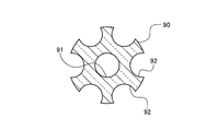
- FIG. 16 is a view showing a modification of the method for producing a multi-core fiber preform according to the third embodiment of the present invention.
- FIG. 17 is a view showing a modification of the method for manufacturing a multi-core fiber preform according to the third embodiment of the present invention.
- FIG. 14 is a view showing a modification of the method for producing a multi-core fiber preform according to the third embodiment of the present invention.
- FIG. 15 is a view showing a modification of the method for producing a multi-core fiber preform according to the third embodiment of the present invention.
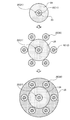
- FIG. 18 is a flowchart of a method for manufacturing a multi-core fiber preform according to the fourth embodiment of the present invention.
- FIG. 19 is a schematic explanatory diagram of a method for manufacturing a multi-core fiber preform according to a fourth embodiment of the present invention.
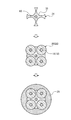
- FIG. 20 is a diagram illustrating a case where the core base material is arranged in a polygonal shape.
- the multi-core fiber preform 1 manufactured by the method for manufacturing the multi-core fiber preform 1 (optical fiber preform) according to the first embodiment of the present invention will be described.
- the multi-core fiber preform 1 includes a plurality of core portions 10 and a clad portion 13 formed on the outer periphery of the core portions 10.
- the plurality of core portions 10 includes a central core portion 11 provided on the central axis of the multi-core fiber preform 1 and a plurality of outer peripheral core portions 12 provided on the outer periphery of the central core portion 11.
- Each core 10 is made of, for example, quartz glass having a high refractive index doped with germanium or the like.
- the clad portion 13 is made of a material having a refractive index lower than that of the core.
- the clad portion 13 is made of pure quartz glass to which a dopant for adjusting the refractive index is not added.
- the manufacturing method of the multi-core fiber preform 1 and the manufacturing method of the multi-core fiber according to the first embodiment of the present invention will be described.
- the manufacturing method of the multi-core fiber preform 1 according to the first embodiment includes a first core preform placement step S01, a first cladding portion placement step S02, and a second cladding portion placement.
- An installation step S03, a dehydration step S04, and a sintering step S05 are provided.
- the first core base material disposing step S01 and the first clad portion disposing step S02 constitute a first base material preparing step.
- the core preform 20 that is the first glass preform includes a core portion 10 that is a core portion of the optical fiber preform, and a clad portion 23 that is formed so as to surround the core portion 10. And has a cylindrical shape extending in one direction.
- the clad part 23 is a part which becomes a part of the clad part 13 of the multi-core fiber preform 1, and for example, the same material as the clad part 13, a material having the same refractive index as the clad part 13, or a refractive index higher than that of the clad part 13. Is made of low material.
- the core base material 20 can be manufactured using a known method such as a VAD (Vapor Phase Axial Deposition) method, an OVD (Outside Vapor Deposition) method, or an MCVD (Modified Chemical Vapor Deposition) method.
- VAD Vapor Phase Axial Deposition
- OVD Outside Vapor Deposition
- MCVD Modified Chemical Vapor Deposition
- a central core preform as a central glass preform that is one of the glass preforms at a position corresponding to the central axis of the multi-core fiber preform 1.
- a peripheral glass base material 22 as an peripheral glass base material which is at least one of the other glass base materials is disposed on the outer peripheral side of the central core base material 21.
- An outer peripheral glass base material arranging step is performed.
- the outer peripheral core base material 22 is arranged such that the distance from the central core base material 21 is equal and the distance between adjacent outer core base materials 22 is equal.
- the distance between the central core base material 21 and the outer core base material 22 is determined in consideration of volume shrinkage in a sintering process described later.
- the core preform 20 disposed on the outer periphery of the central core preform 21 is a dummy preform 31 of the core preform 20 (central core preform 21) disposed at a position corresponding to the central axis of the multi-core fiber preform 1. It is preferably longer and thicker than the dummy base material 32 of the (outer core base material 22). Thereby, it becomes easy to grip only the dummy base material 31 of the central core base material 21 in a later step, and the multi-core fiber base material 1 as a whole is gripped by gripping only the dummy base material 31 of the central core base material 21. Can hold.
- the core base material 20 is attached to the gripping tool 33 of the base material manufacturing apparatus.
- the core base material 20 is disposed at a predetermined position.
- the gripping tool 33 grips the portion of the dummy base material 30 of the core base material 20.
- the gripping tool 33 can rotate (revolve) the entire core base material 20 around the central axis of the central core base material 21 while maintaining the positional relationship between the core base materials 20.
- each core base material 20 may have a structure that can rotate (rotate) around the axis of the core base material 20.
- metal, Teflon (registered trademark), or the like can be used as the material of the gripper 33.
- the first cladding part 24 is disposed by forming the first cladding part 24 so as to fill the gaps between the core base materials 20 arranged as described above.
- the first clad portion 24 is formed around the core base material 20 (particularly the central core base material 21) by the glass fine particle supply unit provided in the base material manufacturing apparatus. It is formed by depositing glass particles.
- a glass fine particle supply unit (not shown) supplies the glass raw material gas and the H 2 gas and the O 2 gas, which are combustion gases, to the burner 36 for synthesizing the glass fine particles and ejects them.
- the glass source gas for example, SiCl 4 gas or the like can be used.
- the burner 36 synthesizes glass particles by flame hydrolysis of the glass raw material gas in a flame formed by the combustion gas.
- glass fine particles are deposited so as to fill the gaps between the core base materials 20 from the gaps between the adjacent outer peripheral core base materials 22, and the first clad made of glass fine particles.
- Part 24 is formed.
- the first clad portion 24 is formed so as to cover all the lines L connecting the centers of the core base materials 20.
- the 1st clad part 24 is arrange
- the burner 36 and the core base material 20 can reciprocate relatively in the extending direction of the core base material 20, and the glass particles are uniformly distributed in the extending direction of the core base material 20.
- the burner 36 is moved to deposit the glass particles.
- the burner 36 may be fixed and the core base material 20 may be reciprocated. Further, the burner 36 is provided so as to be able to advance and retreat in a direction perpendicular to the axis of the central core base material 21.
- the center core base material 21 is moved around the central axis.
- the entire core base material 20 is rotated (revolved) by 60 °, and the burner 36 is moved between other adjacent outer core base materials 22 to reciprocate a predetermined number of times to deposit glass particles. It is preferable to form the first clad portion 24 by repeating this.
- the central portion of the core base material 21 is deformed because the heated portion becomes too hot. Therefore, when a plurality of burners are used as in the present embodiment, it is preferable to reciprocate the burners 36 so that each burner 36 heats another position in the extending direction of the core base material 20. One burner 36 may be used. Further, until the first clad portion 24 is formed, glass fine particles may be deposited while the central core base material 21 is rotated (rotated) around the axis of the central core base material. Thereby, the first clad portion 24 can be uniformly formed on the outer periphery of the central core base material 21.
- the glass fine particles may be deposited while rotating (spinning) all the core base materials 20 around the axis of each core base material. Thereby, it can suppress that the clearance gap between the adjacent outer periphery core base materials 22 is blocked
- a preferable bulk density is 0.5 g / cm 3 or more.
- the same number of baking burners as the number of burners 36 for supplying glass raw materials, and the corresponding burners 36 and the same position in the extending direction of the core base material 20 are heated from the gap between the adjacent outer core base materials 22.
- it may be provided so as to be heated after the burner 36 from the gap between the adjacent outer peripheral core base materials 22 same as the corresponding burner 36.
- the first cladding portion 24 is filled with substantially half or more of the outer core core material 22 so that all the lines L connecting the centers of the outer core core material 22 are covered. Is preferred. As a result, voids are not formed in the second clad portion disposing step described next, and glass particles can be deposited.
- the core base material 20 that is a plurality of glass base materials, and the first clad portion 24 disposed between the core base materials 20 and A first base material having is prepared.
- the first clad portion 24 is preferably arranged so that the cross section of the first base material (see FIG. 5A) approaches a circle. As a result, the cross section of the porous base material 38 formed thereafter is likely to be circular.
- the second clad part 25 it is preferable to deposit glass fine particles while rotating the core base material 20 around the central axis of the central core base material 21 as shown in FIG. 7.
- FIG. 8 is a schematic explanatory diagram of the electric furnace 40 used in the dehydration step S04 and the sintering step S05.
- the dehydration step S04 and the sintering step S05 are performed as follows.
- the electric furnace 40 includes a rotary elevating mechanism 41 having a gripping portion 41a for gripping a porous base material 38, a quartz glass core tube 43 that accommodates an object, an upper lid 42 of the core tube 43, and a core.
- a heater 44 that is provided on the outer periphery of the tube 43 and heats the porous base material 38 from the outside, and a furnace body 46 that accommodates the heater 44 via the heat insulating material 45 on the outer periphery of the core tube 43.
- the core tube 43 has a gas supply port 47 for supplying an inert gas such as nitrogen gas or helium gas, or a dehydrated gas such as chlorine gas into the core tube 43 at the bottom, and used gas at the core tube.
- 43 is provided at the top with a gas exhaust port 48 for exhausting it to the outside.
- an inert gas such as helium (He) or a dehydrated gas such as chlorine gas (Cl 2 ) is required inside the core tube 43 from the gas supply port 47 for dehydration and sintering.
- a predetermined amount of gas is introduced and a suitable amount of gas is discharged from the gas discharge port 48, whereby the pressure in the core tube 43 is maintained at a predetermined value.
- the porous base material 38 is held by the dummy base material 31 welded to the central core base material 21 by the gripping portion 41 a of the rotary lifting mechanism 41 and descends while rotating in the core tube 43.
- the dehydration step S04 and the sintering step S05 are not limited to the above, and well-known methods can be used.
- the dehydration and sintering atmosphere may be under reduced pressure, and the heating method may be a soaking method.
- the dehydration step S04 and the sintering step S05 may be performed in separate steps.
- the second clad portion disposing step S03 is performed after the first clad portion disposing step S02.
- a dehydration / sintering step is performed after the first clad portion disposing step S02.
- One clad may be vitrified in advance, and then the second clad portion disposing step S03 may be performed. Thereby, vitrification becomes possible without further restricting movement of the outer peripheral core due to volume shrinkage due to sintering, and a multi-core fiber preform with higher core position accuracy can be obtained.
- the manufacturing method of the multi-core fiber 5 further includes a drawing step S06.
- FIG. 9 is an explanatory diagram showing a drawing apparatus 50 used in the drawing step S06 in the present embodiment. Hereinafter, the drawing step S06 will be described in more detail.
- the multi-core fiber preform 1 is placed in an electric furnace (drawing furnace) of the drawing apparatus 50, and one end of the multi-core fiber preform 1 is heated and melted by the heater 51 in the drawing furnace to vertically align the multi-core fiber 4. Pull the direction downward.
- an ultraviolet curable resin is applied to the outer peripheral surface of the multi-core fiber 4 by the coating device 54 while monitoring the outer diameter of the multi-core fiber 4 drawn by heating and melting with the outer diameter measuring device 53, and then the ultraviolet ray is applied.
- Ultraviolet rays are irradiated by the irradiation device 55, and the applied ultraviolet curable resin is cured to form a primary coating layer.
- an ultraviolet curable resin is further applied onto the primary coating layer by the coating device 56, and then the ultraviolet radiating device 57 is irradiated with ultraviolet rays to cure the applied ultraviolet curable resin to provide a secondary coating.
- a layer is formed and the coated multi-core fiber 5 is obtained.
- the number of coating layers to be formed is appropriately adjusted according to the purpose of use of the multi-core fiber 5, and the number of coating devices, ultraviolet irradiation devices, and outer diameter measuring devices according to the number of coating layers are arranged.
- the guide roller 58 guides the multi-core fiber 5 on which the coating layer is formed to the winder 59, and the winder 59 winds the multi-core fiber 5 around the bobbin. In this way, the multi-core fiber 5 having the coating layer is manufactured.
- the plurality of core preforms 20 and the first clad disposed between the plurality of core preforms 20 Since the first base material preparing step for preparing the first base material having the portion 24 is performed, the gaps between the plurality of core base materials 20 can be reliably filled with the glass fine particles, and the voids, internal deformation, Alternatively, it is possible to manufacture a high-quality multi-core fiber preform 1 with less distortion (appropriately set as a gap or the like). Since the multi-core fiber 5 manufactured using such a multi-core fiber preform 1 is suppressed in deformation and distortion, it is a high-quality one that can obtain better characteristics.
- the glass fine particles are deposited from the gaps between the adjacent outer core preforms 22 in the first cladding portion arranging step S02. Therefore, the gap between the central core base material 21 and the outer core base material 22 and the gap between the adjacent outer core base materials 22 can be reliably filled with the glass fine particles.
- the glass particles are deposited while rotating the central core preform 21 and the outer core preform 22 around the central axis of the multi-core fiber preform 1.
- the second cladding part 25 can be more reliably formed into a circular cross section.
- a marker M made of a glass rod is disposed at a position where the second clad portion 25 is formed, and the core portion is disposed on the second clad portion 25. It is also possible to provide a marker M for specifying the position of the.
- a glass rod made of glass having a refractive index different from that of the second clad portion 25 after sintering, or a glass made of colored glass can be used.
- the manufacturing method of the multi-core fiber preform 1 according to the second embodiment is the same as the flow shown in FIG. 2, but in the first preform preparation process, the first core preform arrangement process is performed as the first core preform arrangement process.
- the first core base material arranging step S11 is provided instead of the setting step S01
- the first clad portion arranging step S12 is provided instead of the first clad portion arranging step S02 as the first clad portion arranging step. Is different. Since the second clad portion disposing step S03, the dehydrating step S04, and the sintering step S05 have the same configuration as the method for manufacturing the multi-core fiber preform 1 according to the first embodiment, detailed description thereof is omitted.
- First core preform arrangement step S11 In the first core preform arrangement step S11, the outer core preform 22 is arranged on the outer periphery of the central core preform 21, as shown in FIG. As a result, the core base material 20 is disposed at a predetermined position. At this time, when the central core base material 21 and the outer peripheral core base material 22 are arranged so as to be in contact with each other, the outer diameters of the core portion and the clad portion of each core base material 20 are set so that the distance between the cores becomes a desired distance. The ratio is preferably adjusted. Thereby, each core base material 20 can be arrange
- each including a through hole having a shape substantially equal to the outer peripheral shape of the core base material 20 are provided at both ends of the core base material 20 disposed at a predetermined position. Is preferred. Thereby, each core base material 20 can be arrange
- positioning process which arrange
- the glass rod 60 is made of the same material as the clad part 13 or a material having the same refractive index as that of the clad part 13. Further, the glass fine particles 61 are deposited so as to fill the gaps between the outer peripheral core base materials 22 as in the first embodiment.
- the first clad portion 24 composed of the glass rod 60 and the glass fine particles 61 is disposed. Also in this case, the first clad portion 24 is disposed so that all the lines connecting the centers of the core base material 20 are covered.
- the second clad portion 25 is disposed in the second clad portion disposing step S03. Thereafter, the dehydration step S04 and the sintering step S05 are sequentially performed, and the multi-core fiber preform 1 according to the second embodiment is manufactured.
- the core base material 20 made of glass is in close contact with each other, even if the glass fine particles 61 are sintered, the outer core base material 22 may move due to volume shrinkage due to the sintering. Absent. Therefore, in the second clad portion disposing step S03, one dummy base material that holds the core base material 20 together may be provided at each end.
- the gap can be reliably filled with the glass rod 60, and the occurrence of voids or the like in the clad portion 13 of the multi-core fiber preform 1 can be suppressed.
- the manufacturing method of the multi-core fiber preform 1 according to the third embodiment includes a first clad portion arrangement and a first core preform arrangement process S21 as a first preform preparation process, A two-clad portion disposing step S03, a dehydrating step S04, and a sintering step S05 are provided. Since the second clad portion disposing step S03, the dehydrating step S04, and the sintering step S05 have the same configuration as that of the first embodiment, detailed description thereof is omitted.
- the center glass preform placement step is performed in the first core preform placement step, and then the first cladding portion placement step is performed. Thereafter, an outer peripheral glass base material arranging step is performed. That is, as shown in FIG. 13, first, one core base material 20 (central core base material 21) is disposed. Next, glass fine particles are deposited on the central core base material 21 so as to surround the central core base material 21, thereby forming the first cladding portion 24. At this time, similarly to the case of FIG.
- the raw material gas and the combustion gas are ejected from the burner to generate glass fine particles, the central core base material 21 and the burner are relatively moved in the longitudinal direction of the central core base material 21, and the center Glass fine particles are deposited on the core base material 21.
- a recess 70 corresponding to the shape of the outer core base material 22 is formed by a shaving process at a predetermined position of the first clad portion 24 (position where the outer core base material 22 is disposed) (recess forming step). ).
- the distance between the central core base material 21 and the outer core base material 22 is determined in consideration of volume shrinkage in a sintering process described later.
- the first clad portion 24 is dehydrated and further vitrified until the bubbles remain (a semi-sintered glass state or a semi-transparent glass state) or until the bubbles disappear.
- the recess 70 may be formed by shaving after the glass has been formed.
- the first clad portion 24 made of semi-sintered glass has a hardness that can be easily cut, so that the cutting is facilitated and the recess 70 is easily formed.
- an outer peripheral glass base material arranging step is performed. That is, the outer peripheral core base material 22 is disposed at the position of the recess 70 formed in the first cladding portion 24. Accordingly, the outer core base material 22 is disposed at a predetermined position. Also in this case, the first clad portion 24 may be disposed so as to cover all the lines connecting the centers of the core base material 20.
- the outer core preform 22 is disposed on the first clad portion 24 in the first clad portion disposing step. Since the recessed part 70 for accommodating is provided, the clearance gap between the center core base material 21 and the outer periphery core base material 22 can be filled reliably.
- FIG. As shown, for example, the same material or the clad part 13 as the clad part 13 in which the concave part 82 and the through hole 81 according to the shape of the core base material 20 are formed by the powder molding method described in Japanese Patent Application Laid-Open No. 6-51139 or the like.
- a silica molded body 80 as a columnar member made of a material having the same refractive index as the above is manufactured, a through hole 81 is provided at the center, and the central core base material 21 and the outer core base material 22 are disposed at predetermined positions. It may be configured. Further, as shown in FIG. 15, the central core base material 21 may be arranged in the center of the silica molded body 80 in advance when the silica molded body 80 is molded. Further, as shown in FIG.
- Quartz glass material 90 may be used.
- the quartz glass material 90 it is preferable to use a spacer made of the same material as that of the clad portion, as in the second embodiment, and in the second clad portion arranging step S03, the core base material is used.
- One dummy base material that holds 20 together can be provided at each end.
- first clad portion arrangement, the first core preform arrangement step, and the second clad portion arrangement step may be as shown in FIG.
- one core base material 20 central core base material 21
- glass fine particles are deposited on the central core base material 21 so as to surround the central core base material 21, thereby forming the first cladding portion 24.
- the outer peripheral core base material 22 is disposed so as to circumscribe the outer periphery of the first cladding portion 24 or provide a slight gap with respect to the outer periphery.
- glass fine particles are deposited so as to surround the outer core base material 22 and the first cladding part 24, thereby forming the second cladding part 25.
- the outer periphery core base material 22 after making the 1st clad part 24 into a semi-sintered glass state or a glass state.
- position the outer periphery core base material 22 after making the 1st clad part 24 into a semi-sintered glass state or a glass state.
- first clad portion 24 instead of making the first clad portion 24 into a semi-sintered glass state or a glass state, only the outer peripheral surface of the first clad portion 24 is obtained by baking the outer periphery of the first clad portion 24 with a baking burner or the like. High density may be used.
- the manufacturing method of the multi-core fiber preform 1 includes a first core preform arrangement step S01, a first cladding portion arrangement step S02, and a second cladding portion arrangement.
- the second core base material disposing step S31 After performing the first core base material disposing step S01, the first clad portion disposing step S02, and the second clad portion disposing step S03 in this order, the second core base material disposing step S31 is performed.
- the second core preform arrangement step S31 as shown in FIG. 19, at least one second core preform 29 as a second glass preform is placed at a predetermined position on the outer peripheral side of the second cladding portion 25. Arrange.
- the second clad part 25 and the second core base material 29 are arranged so as to be in contact with each other, the thickness of the second clad part 25 and the second core are set so that the distance between the core base materials becomes a desired distance.
- the outer diameter ratio of the core portion and the clad portion of the base material 29 is adjusted.
- the interval between the core base materials is preferably determined in consideration of volume shrinkage of the glass fine particles during sintering. Thereby, while being able to arrange
- silica fine particles are deposited so as to surround the second cladding part 25 and the second core base material 29 to form the third cladding part 26 as in the second cladding part arranging step S03.
- the raw material gas and the combustion gas are ejected from the burner to generate glass fine particles, and the second cladding portion 25 and the burner are relatively moved in the longitudinal direction of the core base material 20, and the second Glass fine particles are deposited on the cladding portion 25.
- the third clad portion disposing step S32 may be performed in two steps, the first core base material disposing step S01, the first clad portion disposing step S02, and the first core base material disposing step.
- the dewatering step S04 and the sintering step S05 are performed in order, and the multi-core fiber preform 1 according to the fourth embodiment is manufactured. And the drawing process S06 is performed similarly to 1st embodiment using this multi-core fiber preform 1, and the multi-core fiber 5 is manufactured.
- the manufacturing method of the multi-core fiber preform 1 according to the fourth embodiment of the present invention configured as described above, after the second clad portion disposing step S03, at least one outer periphery of the second clad portion 25 is provided.
- the second core base material disposing step S31 for disposing the core base material 20 and the at least one core base material 20 disposed in the second clad portion 25 and the second core base material disposing step S31 are enclosed.
- a third clad portion disposing step S32 for depositing glass fine particles and disposing the third clad portion 26 is provided.
- the dehydration step S04 and the sintering step S05 are performed to vitrify the first clad portion 24 and the second clad portion 25. At this time, until the glass is completely transparent. You may keep in a semi-sintered glass state or a semi-transparent glass state, without vitrifying.
- the “semi-transparent glass state” refers to a state in which closed cells are contained almost uniformly as a whole and are cloudy and opaque in appearance.
- the “transparent glass state” is a state that is transparent in appearance in a state that does not contain closed cells almost uniformly except for the minute closed cells that remain in some defective portions.
- the “closed cell” refers to a bubble or space formed inside the translucent glass layer and physically separated from the surrounding atmosphere. Since the bubbles inside the multi-core fiber preform 1 in such a semi-sintered glass state can be eliminated in the subsequent drawing step S06, it can be prevented from remaining in the multi-core fiber 4. Thus, if the optical fiber preform is formed in a semi-sintered state and the internal bubbles are eliminated in the subsequent drawing process, the energy required for heating to completely sinter the optical fiber preform is obtained. Can save.
- the clad part 25 can be a translucent glass layer containing closed cells having a substantially vacuum inside.
- “Vacuum” refers to the definition in JIS Z 8126, that is, “a state of a specific space filled with a gas having a pressure lower than atmospheric pressure”.
- Dehydration conditions Dehydration temperature: 1100 ° C Dehydration time: 3 hours Base material rotation speed: 10 revolutions / minute Gas type and flow rate: Nitrogen 10 liters / minute Chlorine 0.5 liters / minute Sintering conditions Sintering temperature: 1400 ° C. Temperature increase rate: 2 ° C./min Sintering temperature holding time: 3 hours Furnace pressure: 100 Pa Base material rotation speed: 10 rotations / minute
- the first clad part 24 and the second clad part 25 at the stage where the dehydration process and the sintering process are finished are in a state of containing closed cells that are physically separated from the surrounding atmosphere.
- closed cells which are air bubbles physically separated from the surrounding atmosphere, are contained almost uniformly as a whole, and the appearance is cloudy and opaque.
- the surface is smooth and glossy.
- the density of the first cladding part 24 and the second cladding part 25 at this time is, for example, 95% of the density (quartz glass density, 2.2 g / cm 3 ) when the glass finally becomes completely transparent, That is, 2.09 g / cm 3 .
- the average density is 1.8 g / cm 3 or more, preferably 2.0 g. / Cm 3 or more is sufficient.
- the pressure in the sintering process is particularly preferably 1000 Pa or less in order to minimize the residual bubbles in the drawing process.
- the core position accuracy is high, and a large multi-core fiber preform can be manufactured.
- the present invention is not limited to the above embodiment. What was comprised combining each component mentioned above suitably is also contained in this invention. Further effects and modifications can be easily derived by those skilled in the art. Therefore, the broader aspect of the present invention is not limited to the above-described embodiment, and various modifications can be made.
- the present invention can be applied to a case where a hollow glass capillary is used in place of the core base material to form an optical fiber having holes.
- the number of optical fiber preforms and optical fiber cores manufactured according to the present invention is not limited to 7, 19.
- the case where the outer peripheral core base material 22 is disposed around the central core base material 21 has been described.
- the core base material is disposed in an annular shape or a polygonal shape without the central core. It is good also as a structure.
- a glass rod made of, for example, the same material as the clad portion may be provided instead of the central core base material. That is, for example, in the case of arranging in a quadrangular shape, as shown in FIG.
- a glass rod 60 made of the same material as that of the clad portion 13 is arranged, and glass particles 60 are placed so as to surround the glass rod 60.
- the first clad portion 24 is deposited to form a concave portion 70 corresponding to the shape of the outer core base material 22 at a predetermined position of the first clad portion 24 by shaving.
- the core preform 20 (outer core preform 22) is disposed at the position of the recess 70 formed in the first clad portion 24.
- glass fine particles are deposited so as to surround the outer core base material 22 to form the second clad portion 25.
- the outer peripheral core base material 22 after the first cladding portion 24 is formed and then the first cladding portion 24 is further in a semi-sintered glass state.
- the outer periphery of the first cladding portion 24 may be baked with a baked burner instead of making the first cladding portion 24 in a semi-sintered glass state.
- the first clad portion is disposed by the powder molding method, it is not necessary to dispose a glass rod at the center, and a solid powder compact may be prepared.
- the present invention is particularly effective when manufacturing an optical fiber preform and an optical fiber when the number of core portions is 3 or more, and the arrangement of the core portions in the cross section of the optical fiber is a regular polygon or a circle. This is particularly effective in the case where the configuration is arranged as described above.
- a method of depositing the glass fine particles a method of spraying and dropping a combustible Si source (for example, OMCTS (octamethylcyclotetrasiloxane)) and burning it may be used.
- a combustible Si source for example, OMCTS (octamethylcyclotetrasiloxane)
- the method for manufacturing an optical fiber preform and the method for manufacturing an optical fiber according to the present invention are suitable mainly for multi-core fibers.
Landscapes
- Chemical & Material Sciences (AREA)
- Engineering & Computer Science (AREA)
- Geochemistry & Mineralogy (AREA)
- Life Sciences & Earth Sciences (AREA)
- General Life Sciences & Earth Sciences (AREA)
- Manufacturing & Machinery (AREA)
- Materials Engineering (AREA)
- Organic Chemistry (AREA)
- Chemical Kinetics & Catalysis (AREA)
- General Chemical & Material Sciences (AREA)
- Physics & Mathematics (AREA)
- Optics & Photonics (AREA)
- General Physics & Mathematics (AREA)
- Manufacture, Treatment Of Glass Fibers (AREA)
Abstract
複数のガラス母材と、前記複数のガラス母材同士の間に配置された第一クラッド部を有する第一母材を準備する第一母材準備工程と、前記第一母材を囲むように第二クラッド部を配設する第二クラッド部配設工程と、を備え、前記第二クラッド部配設工程は、原料ガスおよび燃焼ガスをバーナから噴出させてガラス微粒子を生成し、前記第一母材と前記バーナを前記第一クラッド部の長手方向に相対移動させ、前記第一クラッド部に前記ガラス微粒子を堆積する光ファイバ母材の製造方法。
Description
本発明は、光ファイバ母材の製造方法、及び光ファイバの製造方法に関するものである。
マルチコアファイバ(Multi-Core Fiber:MCF)は、1本の光ファイバに複数のコアを備えた光ファイバであり、省スペースに多くのコア部を設けることができる新しいタイプの光ファイバである。このマルチコアファイバにより、大容量のイメージ伝送や空間多重伝送等の新たな光伝播の実現が期待されている。
マルチコアファイバの製造方法としては、例えばスタック&ドロー法やドリル法などがある。
スタック&ドロー法とは、コアを形成するためのガラスロッド(コア母材)の周囲に、屈折率がコアよりも低いクラッドを形成するためのガラスロッドを配置し、これらをガラスからなるジャケット管の内部に挿入したものを加熱延伸して光ファイバ母材を形成するというものである(例えば特許文献1参照)。
また、ドリル法とは、ガラスからなるロッド状の元材にドリルで空孔(貫通孔)を形成し、この空孔にコアを形成するためのガラスロッド(コア母材)を挿入して、光ファイバ母材を形成するというものである(例えば特許文献2参照)。
スタック&ドロー法とは、コアを形成するためのガラスロッド(コア母材)の周囲に、屈折率がコアよりも低いクラッドを形成するためのガラスロッドを配置し、これらをガラスからなるジャケット管の内部に挿入したものを加熱延伸して光ファイバ母材を形成するというものである(例えば特許文献1参照)。
また、ドリル法とは、ガラスからなるロッド状の元材にドリルで空孔(貫通孔)を形成し、この空孔にコアを形成するためのガラスロッド(コア母材)を挿入して、光ファイバ母材を形成するというものである(例えば特許文献2参照)。
しかしながら、スタック&ドロー法では、コア母材をジャケット管内部に挿入して加熱延伸するため、コアの位置精度が低下してしまう問題があった。また、ドリル法では、ロッド状の元材にドリルで空孔を形成するため、加工費が高くなり、高コストとなってしまう問題があった。
そこで、特許文献3には、コアを形成するための複数のコア母材を所定の位置に配列し、これらのコア母材の外側からガラス微粒子を堆積し、クラッドとなる多孔質層を形成した後、さらに焼結することによってマルチコアファイバ母材を得るマルチコアファイバ母材の製造方法が開示されている。
そこで、特許文献3には、コアを形成するための複数のコア母材を所定の位置に配列し、これらのコア母材の外側からガラス微粒子を堆積し、クラッドとなる多孔質層を形成した後、さらに焼結することによってマルチコアファイバ母材を得るマルチコアファイバ母材の製造方法が開示されている。
しかしながら、特許文献3に記載のマルチコアファイバ母材の製造方法のように、配置したコア母材の外側からガラス微粒子を堆積し、クラッドを形成する場合、コア母材の間の隙間を十分に埋めることができない場合があった。この場合、その後焼結を行っても、コアで囲まれる内部の領域に大きな空隙が生じたり、焼結時にその空隙が埋められるのに伴ってマルチコアファイバ母材に変形や歪が生じ、母材が割れたり、コアの位置精度が低下する等の問題が生じる場合があった。さらに、このマルチコアファイバ母材からマルチコアファイバを線引きしたときには、光ファイバ内に空隙が生じたり、コアの位置精度が低下する等、マルチコアファイバの品質が低下してしまう場合があった。
本発明は、上記に鑑みてなされたものであって、低コストで良質な光ファイバ母材を製造することができるマルチコアファイバ母材の製造方法、及びこれを用いた光ファイバの製造方法を提供することを目的とする。
上述した課題を解決し、目的を達成するために、本発明のマルチコアファイバ母材の製造方法は、複数のガラス母材と、前記複数のガラス母材同士の間に配置された第一クラッド部を有する第一母材を準備する第一母材準備工程と、前記第一母材を囲むように第二クラッド部を配設する第二クラッド部配設工程と、を備え、前記第二クラッド部配設工程は、原料ガスおよび燃焼ガスをバーナから噴出させてガラス微粒子を生成し、前記第一母材と前記バーナを前記第一クラッド部の長手方向に相対移動させ、前記第一クラッド部に前記ガラス微粒子を堆積することを特徴とする。
また、本発明のマルチコアファイバ母材の製造方法の一態様は、前記第一クラッド部は、前記第一母材の断面が円形に近づくように配置されることを特徴とする。
また、本発明のマルチコアファイバ母材の製造方法の一態様は、前記第一母材準備工程は、前記複数のガラス母材の一つである中心ガラス母材を配設する中心ガラス母材配設工程と、前記中心ガラス母材の外周に前記複数のガラス母材の他の少なくとも一つである外周ガラス母材を配設する外周ガラス母材配設工程と、原料ガスおよび燃焼ガスをバーナから噴出させてガラス微粒子を生成し、配設された前記複数のガラス母材と前記バーナを前記複数のガラス母材の長手方向に相対移動させ、前記中心ガラス母材に前記ガラス微粒子を堆積する第一クラッド部配設工程と、を有することを特徴とする。
また、本発明のマルチコアファイバ母材の製造方法の一態様は、前記第一クラッド部配設工程において、前記複数のガラス母材をそれぞれのガラス母材の中心軸回りに回転させながら前記中心ガラス母材に前記ガラス微粒子を堆積することを特徴とする。
また、本発明のマルチコアファイバ母材の製造方法の一態様は、前記第一母材準備工程は、隣接する前記複数のガラス母材同士の間の隙間に、ガラスロッドを配置するガラスロッド配置工程を有することを特徴とする。
また、本発明のマルチコアファイバ母材の製造方法の一態様は、前記第一母材準備工程は、前記複数のガラス母材の一つである中心ガラス母材を配設する中心ガラス母材配設工程と、原料ガスおよび燃焼ガスをバーナから噴出させてガラス微粒子を生成し、配設された前記中心ガラス母材と前記バーナを前記中心ガラス母材の長手方向に相対移動させ、前記中心ガラス母材に前記ガラス微粒子を堆積する第一クラッド部配設工程と、前記第一クラッド部を配設した前記中心ガラス母材の外周に前記複数のガラス母材の他の少なくとも一つである外周ガラス母材を配設する外周ガラス母材配設工程と、を有することを特徴とする。
また、本発明のマルチコアファイバ母材の製造方法の一態様は、第一クラッド部配設工程の後に、前記第一クラッド部の外周に前記第一母材の長手方向に延在する凹部を形成する凹部形成工程を有し、前記外周ガラス母材配設工程は、前記凹部に対応する位置に前記外周ガラス母材を配設することを特徴とする。
また、本発明のマルチコアファイバ母材の製造方法の一態様は、前記第一クラッド部は、前記第一母材の長手方向に延在する凹部が形成された円柱状部材であり、前記第一母材準備工程は、前記凹部に対応する位置に前記ガラス母材を配設するガラス母材配設工程を有することを特徴とする。
また、本発明のマルチコアファイバ母材の製造方法の一態様は、前記第一クラッド部は、粉末成形体からなることを特徴とする。
また、本発明のマルチコアファイバ母材の製造方法の一態様は、前記第一クラッド部は、ガラスからなることを特徴とする。
また、本発明のマルチコアファイバ母材の製造方法の一態様は、前記第一クラッド部は、半焼結ガラスからなることを特徴とする。
また、本発明のマルチコアファイバ母材の製造方法の一態様は、前記第二クラッド部配設工程の後に、さらに、第二クラッド部の外周に少なくとも一つのガラス母材を配設する第二ガラス母材配設工程と、原料ガスおよび燃焼ガスをバーナから噴出させてガラス微粒子を生成し、配設された前記第二クラッド部と前記バーナを前記複数のガラス母材の長手方向に相対移動させ、前記第二クラッド部に前記ガラス微粒子を堆積して第三クラッド部を配設する第三クラッド部配設工程と、を備えることを特徴とする。
また、本発明の光ファイバの製造方法は、上述の光ファイバ母材の製造方法によって製造された光ファイバ母材を線引きすることを特徴とする。
本発明によれば、クラッドでの空隙の発生を無くし、コア位置精度を高くできるので、低コストで良質なマルチコアファイバ母材およびマルチコアファイバを製造することができる。
以下に、図面を参照して本発明の実施形態に係るマルチコアファイバ母材の製造方法、及びマルチコアファイバの製造方法についての実施の形態を説明する。なお、この実施の形態によりこの発明が限定されるものではない。また、図面の記載において、同一または対応する要素には適宜同一の符号を付している。また、図面は模式的なものであり、各要素の寸法の関係、各要素の比率などは、現実と異なる場合があることに留意する必要がある。図面の相互間においても、互いの寸法の関係や比率が異なる部分が含まれている場合がある。
(第一実施形態)
まず、本発明の第一実施形態に係るマルチコアファイバ母材1(光ファイバ母材)の製造方法によって製造されるマルチコアファイバ母材1について説明する。このマルチコアファイバ母材1は、図1に示すように、複数のコア部10と、これらのコア部10の外周に形成されたクラッド部13とを備えている。
複数のコア部10は、マルチコアファイバ母材1の中心軸に設けられた中心コア部11と、この中心コア部11の外周に設けられた複数の外周コア部12とから構成されている。それぞれのコア部10は、例えばゲルマニウムなどがドープされた屈折率の高い石英系ガラスによって構成されている。
クラッド部13は、コアよりも屈折率の低い材料で構成されており、例えば屈折率調整用のドーパントが添加されていない純石英ガラスなどで構成されている。
まず、本発明の第一実施形態に係るマルチコアファイバ母材1(光ファイバ母材)の製造方法によって製造されるマルチコアファイバ母材1について説明する。このマルチコアファイバ母材1は、図1に示すように、複数のコア部10と、これらのコア部10の外周に形成されたクラッド部13とを備えている。
複数のコア部10は、マルチコアファイバ母材1の中心軸に設けられた中心コア部11と、この中心コア部11の外周に設けられた複数の外周コア部12とから構成されている。それぞれのコア部10は、例えばゲルマニウムなどがドープされた屈折率の高い石英系ガラスによって構成されている。
クラッド部13は、コアよりも屈折率の低い材料で構成されており、例えば屈折率調整用のドーパントが添加されていない純石英ガラスなどで構成されている。
次に、本発明の第一実施形態に係るマルチコアファイバ母材1の製造方法、及びマルチコアファイバの製造方法について説明する。
第一実施形態に係るマルチコアファイバ母材1の製造方法は、例えば図2に示すように、第一コア母材配設工程S01と、第一クラッド部配設工程S02と、第二クラッド部配設工程S03と、脱水工程S04と、焼結工程S05とを備えている。ここで、第一コア母材配設工程S01と第一クラッド部配設工程S02とは第一母材準備工程を構成している。
以下に、各工程について詳細に説明する。
第一実施形態に係るマルチコアファイバ母材1の製造方法は、例えば図2に示すように、第一コア母材配設工程S01と、第一クラッド部配設工程S02と、第二クラッド部配設工程S03と、脱水工程S04と、焼結工程S05とを備えている。ここで、第一コア母材配設工程S01と第一クラッド部配設工程S02とは第一母材準備工程を構成している。
以下に、各工程について詳細に説明する。
(第一コア母材配設工程S01)
第一ガラス母材であるコア母材20は、図3A、3Bに示すように、光ファイバ母材のコア部となるコア部10と、このコア部10を囲むように形成されたクラッド部23とから構成されており、一方向に延在する円柱形状をしている。なお、クラッド部23はマルチコアファイバ母材1のクラッド部13の一部となる部分であり、たとえばクラッド部13と同じ材料、クラッド部13と同じ屈折率の材料、またはクラッド部13よりも屈折率が低い材料で構成されている。コア母材20は、VAD(Vapor phase Axial Deposition)法、OVD(Outside Vapor Deposition)法、MCVD(Modified Chemical Vapor Deposition)法などの周知の方法を用いて製造できる。
第一ガラス母材であるコア母材20は、図3A、3Bに示すように、光ファイバ母材のコア部となるコア部10と、このコア部10を囲むように形成されたクラッド部23とから構成されており、一方向に延在する円柱形状をしている。なお、クラッド部23はマルチコアファイバ母材1のクラッド部13の一部となる部分であり、たとえばクラッド部13と同じ材料、クラッド部13と同じ屈折率の材料、またはクラッド部13よりも屈折率が低い材料で構成されている。コア母材20は、VAD(Vapor phase Axial Deposition)法、OVD(Outside Vapor Deposition)法、MCVD(Modified Chemical Vapor Deposition)法などの周知の方法を用いて製造できる。
第一コア母材配設工程S01では、図4Aに示すように、マルチコアファイバ母材1の中心軸に相当する位置に、ガラス母材の一つである中心ガラス母材としての中心コア母材21を配置する中心ガラス母材配設工程を行うとともに、この中心コア母材21の外周側に、ガラス母材の他の少なくとも一つである外周ガラス母材としての外周コア母材22を配置する外周ガラス母材配設工程を行う。外周コア母材22は、たとえば、中心コア母材21との距離が等距離であり、かつ隣接する外周コア母材22同士の距離が等距離となるように配置する。また、このとき中心コア母材21と外周コア母材22の距離は、後述する焼結工程での体積収縮を考慮して決定されていることが好ましい。
図4B、Cに示すように、コア母材20の両端部には、ガラスからなるダミー母材30を溶着することが好ましい。これにより、後述する母材製造装置の把持具でコア母材20を把持する場合、ダミー母材30部分を把持でき、コア母材20の良品部分をより有効に使用できる。
また、マルチコアファイバ母材1の中心軸に相当する位置に配置されるコア母材20(中心コア母材21)のダミー母材31が、中心コア母材21の外周に配置するコア母材20(外周コア母材22)のダミー母材32よりも長く、かつ太いことが好ましい。これにより、後の工程で、中心コア母材21のダミー母材31のみを把持することが容易となり、中心コア母材21のダミー母材31のみを把持することでマルチコアファイバ母材1全体を保持できる。
コア母材20は、母材製造装置の把持具33に取り付けられる。これによってコア母材20が所定の位置に配設される。このとき、把持具33はコア母材20のダミー母材30の部分を把持する。
この把持具33は、コア母材20間の配置関係を維持しつつ、中心コア母材21の中心軸を中心としてコア母材20全体を回転(公転)させることができる。また、さらにそれぞれのコア母材20をコア母材20の軸心回りに回転(自転)させることができる構造としても良い。把持具33の材質としては、金属やテフロン(登録商標)等を用いることができる。
図4B、Cに示すように、コア母材20の両端部には、ガラスからなるダミー母材30を溶着することが好ましい。これにより、後述する母材製造装置の把持具でコア母材20を把持する場合、ダミー母材30部分を把持でき、コア母材20の良品部分をより有効に使用できる。
また、マルチコアファイバ母材1の中心軸に相当する位置に配置されるコア母材20(中心コア母材21)のダミー母材31が、中心コア母材21の外周に配置するコア母材20(外周コア母材22)のダミー母材32よりも長く、かつ太いことが好ましい。これにより、後の工程で、中心コア母材21のダミー母材31のみを把持することが容易となり、中心コア母材21のダミー母材31のみを把持することでマルチコアファイバ母材1全体を保持できる。
コア母材20は、母材製造装置の把持具33に取り付けられる。これによってコア母材20が所定の位置に配設される。このとき、把持具33はコア母材20のダミー母材30の部分を把持する。
この把持具33は、コア母材20間の配置関係を維持しつつ、中心コア母材21の中心軸を中心としてコア母材20全体を回転(公転)させることができる。また、さらにそれぞれのコア母材20をコア母材20の軸心回りに回転(自転)させることができる構造としても良い。把持具33の材質としては、金属やテフロン(登録商標)等を用いることができる。
(第一クラッド部配設工程S02)
次に、前述のように配置されたそれぞれのコア母材20の間の隙間を埋めるように第一クラッド部24を形成することによって、第一クラッド部24を配設する。第一実施形態において、第一クラッド部24は、図5A、5Bに示すように、母材製造装置に備えられたガラス微粒子供給部によってコア母材20(特に中心コア母材21)の周囲にガラス微粒子が堆積されることによって形成される。
本実施形態においては、図示しないガラス微粒子供給部は、ガラス微粒子合成用のバーナ36に、ガラス原料ガス及び燃焼ガスであるH2ガスとO2ガスとを供給し、噴出させる。ガラス原料ガスとしてはたとえばSiCl4ガス等を用いることができる。
次に、前述のように配置されたそれぞれのコア母材20の間の隙間を埋めるように第一クラッド部24を形成することによって、第一クラッド部24を配設する。第一実施形態において、第一クラッド部24は、図5A、5Bに示すように、母材製造装置に備えられたガラス微粒子供給部によってコア母材20(特に中心コア母材21)の周囲にガラス微粒子が堆積されることによって形成される。
本実施形態においては、図示しないガラス微粒子供給部は、ガラス微粒子合成用のバーナ36に、ガラス原料ガス及び燃焼ガスであるH2ガスとO2ガスとを供給し、噴出させる。ガラス原料ガスとしてはたとえばSiCl4ガス等を用いることができる。
このバーナ36は、燃焼ガスによって形成される火炎中でガラス原料ガスを火炎加水分解させてガラス微粒子を合成する。本実施形態においては、図5Aに示すように、隣接する外周コア母材22の間の隙間からコア母材20の間の隙間を埋めるようにガラス微粒子を堆積させ、ガラス微粒子からなる第一クラッド部24を形成する。このとき、コア母材20の中心同士を結ぶ線Lが全て覆われるように第一クラッド部24を形成する。これにより、第一クラッド部24が配設される。
また、図5Bに示すように、バーナ36とコア母材20は、コア母材20の延在方向に相対的に往復移動が可能であり、コア母材20の延在方向に均一にガラス微粒子を堆積させることができる。なお、この実施の形態では、バーナ36を移動させてガラス微粒子を堆積させているが、バーナ36を固定して、コア母材20を往復移動させてもよい。さらに、このバーナ36は、中心コア母材21の軸心に直交する方向に進退可能に設けられている。
また、図5Bに示すように、バーナ36とコア母材20は、コア母材20の延在方向に相対的に往復移動が可能であり、コア母材20の延在方向に均一にガラス微粒子を堆積させることができる。なお、この実施の形態では、バーナ36を移動させてガラス微粒子を堆積させているが、バーナ36を固定して、コア母材20を往復移動させてもよい。さらに、このバーナ36は、中心コア母材21の軸心に直交する方向に進退可能に設けられている。
ここで、コア母材20の間の隙間をより均一に埋めるためには、全ての隣接する外周コア母材22の間から、同量のガラス微粒子を堆積させることが好ましい。したがって、本実施形態のように外周コア母材22が6本であり、バーナ36が3本である場合は、バーナ36を所定回数往復移動させた後、中心コア母材21の中心軸回りにコア母材20全体を60°回転(公転)させ、バーナ36を別の隣接する外周コア母材22の間に移動させて、所定回数往復移動させガラス微粒子を堆積させる。これを繰り返して第一クラッド部24を形成することが好ましい。
また、コア母材20の延在方向の同一箇所を複数のバーナで加熱すると、加熱部位が高温になりすぎて中心コア母材21が変形する等の問題が生じる場合がある。したがって、本実施形態のように複数のバーナを用いる場合は、各バーナ36がコア母材20の延在方向の別の位置を加熱するようにバーナ36を往復移動させることが好ましい。なお、バーナ36は1本でもよい。
また、第一クラッド部24が形成されるまでは、中心コア母材21を中心コア母材の軸心回りに回転(自転)させながらガラス微粒子を堆積させてもよい。これにより、中心コア母材21の外周に均一に第一クラッド部24を形成できる。
さらに、全てのコア母材20を各コア母材の軸心回りに回転(自転)させながらガラス微粒子を堆積させてもよい。これにより、中心コア母材21の外周に隙間を残したまま隣接する外周コア母材22の間の間隙がガラス微粒子で塞がれてしまうことを抑制することができる。
また、堆積するガラス微粒子の嵩密度が低いと、後述する脱水焼結工程での収縮が大きくなり、コア位置精度の低下につながる恐れがある。そのため、バーナ36のほかに、燃焼ガスのみを供給する別の焼き締めバーナをさらに設けて堆積したガラス微粒子を焼き締めて、嵩密度を上げてもよい。好ましい嵩密度は0.5g/cm3以上である。焼き締めバーナは、ガラス原料を供給するバーナ36と同じ数だけ設けることが好ましく、対応するバーナ36とコア母材20の延在方向の同じ位置を隣接する外周コア母材22の間隙から加熱するように設けてもよく、対応するバーナ36と同じ隣接する外周コア母材22の間隙からバーナ36の後を追って加熱するように設けてもよい。
このようにすることで、空隙が形成されることがなく、コア母材20の間の隙間を埋めるようにガラス微粒子を堆積させることができる。
また、このとき、図5Aに示すように、外周コア母材22の中心同士を結ぶ線Lが全て覆われるようにして、外周コア母材22の略半分以上を第一クラッド部24に埋めることが好ましい。これにより次に説明する第二クラッド部配設工程で空隙が形成されることがなく、ガラス微粒子を堆積させることができる。
第一コア母材配設工程S01および第一クラッド部配設工程S02により、複数のガラス母材であるコア母材20と、コア母材20同士の間に配置された第一クラッド部24とを有する第一母材が準備される。なお、このとき、第一クラッド部24は、第一母材の断面(図5A参照)が円形に近づくように配置されることが好ましい。これにより、その後形成される多孔質母材38の断面を円形になりやすくなる。
また、コア母材20の延在方向の同一箇所を複数のバーナで加熱すると、加熱部位が高温になりすぎて中心コア母材21が変形する等の問題が生じる場合がある。したがって、本実施形態のように複数のバーナを用いる場合は、各バーナ36がコア母材20の延在方向の別の位置を加熱するようにバーナ36を往復移動させることが好ましい。なお、バーナ36は1本でもよい。
また、第一クラッド部24が形成されるまでは、中心コア母材21を中心コア母材の軸心回りに回転(自転)させながらガラス微粒子を堆積させてもよい。これにより、中心コア母材21の外周に均一に第一クラッド部24を形成できる。
さらに、全てのコア母材20を各コア母材の軸心回りに回転(自転)させながらガラス微粒子を堆積させてもよい。これにより、中心コア母材21の外周に隙間を残したまま隣接する外周コア母材22の間の間隙がガラス微粒子で塞がれてしまうことを抑制することができる。
また、堆積するガラス微粒子の嵩密度が低いと、後述する脱水焼結工程での収縮が大きくなり、コア位置精度の低下につながる恐れがある。そのため、バーナ36のほかに、燃焼ガスのみを供給する別の焼き締めバーナをさらに設けて堆積したガラス微粒子を焼き締めて、嵩密度を上げてもよい。好ましい嵩密度は0.5g/cm3以上である。焼き締めバーナは、ガラス原料を供給するバーナ36と同じ数だけ設けることが好ましく、対応するバーナ36とコア母材20の延在方向の同じ位置を隣接する外周コア母材22の間隙から加熱するように設けてもよく、対応するバーナ36と同じ隣接する外周コア母材22の間隙からバーナ36の後を追って加熱するように設けてもよい。
このようにすることで、空隙が形成されることがなく、コア母材20の間の隙間を埋めるようにガラス微粒子を堆積させることができる。
また、このとき、図5Aに示すように、外周コア母材22の中心同士を結ぶ線Lが全て覆われるようにして、外周コア母材22の略半分以上を第一クラッド部24に埋めることが好ましい。これにより次に説明する第二クラッド部配設工程で空隙が形成されることがなく、ガラス微粒子を堆積させることができる。
第一コア母材配設工程S01および第一クラッド部配設工程S02により、複数のガラス母材であるコア母材20と、コア母材20同士の間に配置された第一クラッド部24とを有する第一母材が準備される。なお、このとき、第一クラッド部24は、第一母材の断面(図5A参照)が円形に近づくように配置されることが好ましい。これにより、その後形成される多孔質母材38の断面を円形になりやすくなる。
(第二クラッド部配設工程S03)
次いで、第一クラッド部24を形成した後に、図6に示すように、第一母材の外周コア母材22及び第一クラッド部24を囲うようにガラス微粒子を堆積させ、第二クラッド部25を形成する。このとき、図5Bの場合と同様に、原料ガスおよび燃焼ガスをバーナから噴出させてガラス微粒子を生成し、第一母材とバーナを第一クラッド部24の長手方向に相対移動させ、第一クラッド部24にガラス微粒子を堆積する。これにより、第二クラッド部25が配設され、マルチコアファイバ母材1の元母材としての多孔質母材38が形成される。
ここで、第二クラッド部25を形成する際には、図7に示すように、コア母材20を中心コア母材21の中心軸回りに回転させながらガラス微粒子を堆積させることが好ましい。
なお、第二クラッド部25を形成した後に、断面がより真円に近い円形となるように第二クラッド部25に対して削り加工を行っても良い。
次いで、第一クラッド部24を形成した後に、図6に示すように、第一母材の外周コア母材22及び第一クラッド部24を囲うようにガラス微粒子を堆積させ、第二クラッド部25を形成する。このとき、図5Bの場合と同様に、原料ガスおよび燃焼ガスをバーナから噴出させてガラス微粒子を生成し、第一母材とバーナを第一クラッド部24の長手方向に相対移動させ、第一クラッド部24にガラス微粒子を堆積する。これにより、第二クラッド部25が配設され、マルチコアファイバ母材1の元母材としての多孔質母材38が形成される。
ここで、第二クラッド部25を形成する際には、図7に示すように、コア母材20を中心コア母材21の中心軸回りに回転させながらガラス微粒子を堆積させることが好ましい。
なお、第二クラッド部25を形成した後に、断面がより真円に近い円形となるように第二クラッド部25に対して削り加工を行っても良い。
(脱水工程S04、焼結工程S05)
次に、脱水工程S04及び焼結工程S05を行う。図8は、脱水工程S04及び焼結工程S05において用いる電気炉40の概略説明図である。脱水工程S04及び焼結工程S05は以下のようにして行われる。
電気炉40は、多孔質母材38を把持するための把持部41aを有する回転昇降機構41と、対象物を収容する石英ガラス製の炉心管43と、該炉心管43の上蓋42と、炉心管43の外周に備えられ外部から多孔質母材38を加熱するヒータ44と、炉心管43の外周で断熱材45を介してヒータ44を収容している炉体46と、を備えている。
さらに、炉心管43は、窒素ガス、ヘリウムガスなどの不活性ガスや、塩素ガスなどの脱水ガスを炉心管43内に供給するためのガス供給口47を下部に、使用済みのガスを炉心管43外に排出するためのガス排出口48を上部に備える。
次に、脱水工程S04及び焼結工程S05を行う。図8は、脱水工程S04及び焼結工程S05において用いる電気炉40の概略説明図である。脱水工程S04及び焼結工程S05は以下のようにして行われる。
電気炉40は、多孔質母材38を把持するための把持部41aを有する回転昇降機構41と、対象物を収容する石英ガラス製の炉心管43と、該炉心管43の上蓋42と、炉心管43の外周に備えられ外部から多孔質母材38を加熱するヒータ44と、炉心管43の外周で断熱材45を介してヒータ44を収容している炉体46と、を備えている。
さらに、炉心管43は、窒素ガス、ヘリウムガスなどの不活性ガスや、塩素ガスなどの脱水ガスを炉心管43内に供給するためのガス供給口47を下部に、使用済みのガスを炉心管43外に排出するためのガス排出口48を上部に備える。
脱水工程S04、焼結工程S05においては、炉心管43内部には、ガス供給口47からヘリウム(He)等の不活性ガス、塩素ガス(Cl2)等の脱水ガス等、脱水焼結に必要なガスを所定の流量導入し、ガス排出口48から適量のガスを排出することにより、炉心管43内の圧力を所定の値に保っている。
多孔質母材38は、中心コア母材21に溶着されたダミー母材31を回転昇降機構41の把持部41aによって把持され、炉心管43内を回転しながら降下する。これによって、多孔質母材38の端部から順にヒータ44により高温に加熱された領域を通過することで加熱されて脱水される。その後、温度を昇温させてから、脱水時と同様に多孔質母材38の端部から順に高温に加熱された領域を通過することで焼結される。これにより、第一クラッド部24及び第二クラッド部25がガラス化し、マルチコアファイバ母材1が得られる。
このとき、外周コア母材22は把持部41aにより把持されていない。そのため、堆積されたガラス微粒子が焼結して体積が収縮すると、それに合わせて外周コア母材22が中心コア母材21の方向に移動する。これにより外周コア母材22が長手方向に湾曲することを抑制でき、さらにコア位置精度の高いマルチコアファイバ母材1が得られる。
なお、脱水工程S04、焼結工程S05は上記に限らず、周知の方法を用いることができる。たとえば、脱水焼結雰囲気は、減圧下でもよく、また加熱方式も均熱方式でもよい。また、脱水工程S04と焼結工程S05を別の工程で行ってもよい。
また、この実施の形態では、第一クラッド部配設工程S02の後に第二クラッド部配設工程S03を行ったが、第一クラッド部配設工程S02の後に脱水・焼結工程を設けて第一クラッドを予めガラス化し、その後、第二クラッド部配設工程S03を行ってもよい。これにより、焼結による体積収縮による外周コアの移動をより束縛することなくガラス化が可能となり、より一層コア位置精度の高いマルチコアファイバ母材が得られる。
多孔質母材38は、中心コア母材21に溶着されたダミー母材31を回転昇降機構41の把持部41aによって把持され、炉心管43内を回転しながら降下する。これによって、多孔質母材38の端部から順にヒータ44により高温に加熱された領域を通過することで加熱されて脱水される。その後、温度を昇温させてから、脱水時と同様に多孔質母材38の端部から順に高温に加熱された領域を通過することで焼結される。これにより、第一クラッド部24及び第二クラッド部25がガラス化し、マルチコアファイバ母材1が得られる。
このとき、外周コア母材22は把持部41aにより把持されていない。そのため、堆積されたガラス微粒子が焼結して体積が収縮すると、それに合わせて外周コア母材22が中心コア母材21の方向に移動する。これにより外周コア母材22が長手方向に湾曲することを抑制でき、さらにコア位置精度の高いマルチコアファイバ母材1が得られる。
なお、脱水工程S04、焼結工程S05は上記に限らず、周知の方法を用いることができる。たとえば、脱水焼結雰囲気は、減圧下でもよく、また加熱方式も均熱方式でもよい。また、脱水工程S04と焼結工程S05を別の工程で行ってもよい。
また、この実施の形態では、第一クラッド部配設工程S02の後に第二クラッド部配設工程S03を行ったが、第一クラッド部配設工程S02の後に脱水・焼結工程を設けて第一クラッドを予めガラス化し、その後、第二クラッド部配設工程S03を行ってもよい。これにより、焼結による体積収縮による外周コアの移動をより束縛することなくガラス化が可能となり、より一層コア位置精度の高いマルチコアファイバ母材が得られる。
以下に、さらにマルチコアファイバの製造方法を説明する。マルチコアファイバ5の製造方法は、さらに線引工程S06を備えている。
(線引工程S06)
線引工程S06では上述のようにして製造されたマルチコアファイバ母材1を線引きする。図9は、本実施の形態にて線引工程S06に用いる線引装置50を示す説明図である。以下に線引工程S06についてさらに詳細に説明する。
線引工程S06では上述のようにして製造されたマルチコアファイバ母材1を線引きする。図9は、本実施の形態にて線引工程S06に用いる線引装置50を示す説明図である。以下に線引工程S06についてさらに詳細に説明する。
はじめに、マルチコアファイバ母材1を線引装置50の電気炉(線引炉)内に配置し、マルチコアファイバ母材1の一端を線引炉内のヒータ51によって加熱溶融してマルチコアファイバ4を鉛直方向下向きに引き出す。
次に、加熱溶融して引き出されたマルチコアファイバ4の外径を外径測定器53で監視しつつ、マルチコアファイバ4の外周表面に紫外線硬化性樹脂を被覆装置54で塗付し、その後、紫外線照射装置55によって紫外線を照射し、塗布した紫外線硬化性樹脂を硬化させて1次被覆層を形成する。
次に、加熱溶融して引き出されたマルチコアファイバ4の外径を外径測定器53で監視しつつ、マルチコアファイバ4の外周表面に紫外線硬化性樹脂を被覆装置54で塗付し、その後、紫外線照射装置55によって紫外線を照射し、塗布した紫外線硬化性樹脂を硬化させて1次被覆層を形成する。
次に、さらにこの1次被覆層上に紫外線硬化性樹脂を被覆装置56でさらに塗付し、その後、紫外線照射装置57によって紫外線を照射し、塗布した紫外線硬化性樹脂を硬化させて2次被覆層を形成し、被覆したマルチコアファイバ5とする。なお、各紫外線硬化性樹脂した後にも図示しない外径測定器を設けてもよい。また、形成する被覆層の層数はマルチコアファイバ5の使用目的等に応じて適宜調整され、被覆層の層数に応じた数の被覆装置、紫外線照射装置及び外径測定器が配置される。また、複数の被覆層を一括して塗布し、硬化させる方法を用いても良い。
次いで、ガイドローラ58は、被覆層が形成されたマルチコアファイバ5を巻取機59に案内し、巻取機59が、マルチコアファイバ5をボビンに巻き取る。このようにして被覆層を有するマルチコアファイバ5が製造される。
次いで、ガイドローラ58は、被覆層が形成されたマルチコアファイバ5を巻取機59に案内し、巻取機59が、マルチコアファイバ5をボビンに巻き取る。このようにして被覆層を有するマルチコアファイバ5が製造される。
以上のような構成とされた第一実施形態に係るマルチコアファイバ母材1の製造方法によれば、複数のコア母材20と、複数のコア母材20同士の間に配置された第一クラッド部24とを有する第一母材を準備する第一母材準備工程を行うので、確実に複数のコア母材20の間の隙間をガラス微粒子により充填することができ、空隙、内部の変形、または歪(適宜空隙等とする)の少ない良質なマルチコアファイバ母材1を製造することが可能となる。
このようなマルチコアファイバ母材1を用いて製造されるマルチコアファイバ5は、変形や歪が抑制されているので、より良好な特性が得られる良質なものである。
このようなマルチコアファイバ母材1を用いて製造されるマルチコアファイバ5は、変形や歪が抑制されているので、より良好な特性が得られる良質なものである。
また、第一実施形態に係るマルチコアファイバ母材1の製造方法においては、第一クラッド部配設工程S02において、隣接する外周コア母材22の間の隙間からガラス微粒子を堆積させる構成とされているので、確実に中心コア母材21と外周コア母材22との間の隙間、及び隣接する外周コア母材22の間の隙間をガラス微粒子によって埋めることができる。
また、第二クラッド部配設工程S03において、中心コア母材21及び外周コア母材22を、マルチコアファイバ母材1の中心軸を中心に回転させながらガラス微粒子を堆積させる構成とされているので、第二クラッド部25をより確実に断面円形状に形成することができる。
また、図10に示すように、第二クラッド部配設工程S03において、第二クラッド部25を形成する位置に、ガラスロッドからなるマーカMを配置して、第二クラッド部25に、コア部の位置特定等のためのマーカMを設ける構成としてもよい。マーカMとしては、焼結後の第二クラッド部25とは屈折率が異なるガラスからなるガラスロッドや、着色されたガラスからなるものを用いることができる。
(第二実施形態)
次に、本発明の第二実施形態に係るマルチコアファイバ母材1の製造方法、及びマルチコアファイバ5の製造方法について説明する。なお、第一実施形態と同様の構成のものについては、同一の符号を付して記載し、詳細な説明を省略する。
次に、本発明の第二実施形態に係るマルチコアファイバ母材1の製造方法、及びマルチコアファイバ5の製造方法について説明する。なお、第一実施形態と同様の構成のものについては、同一の符号を付して記載し、詳細な説明を省略する。
第二実施形態に係るマルチコアファイバ母材1の製造方法は、図2に示すフローと同様であるが、第一母材準備工程において、第一コア母材配設工程として第一コア母材配設工程S01の代わりに第一コア母材配設工程S11を備え、第一クラッド部配設工程として第一クラッド部配設工程S02の代わりに第一クラッド部配設工程S12を備えている点が異なる。第二クラッド部配設工程S03と、脱水工程S04と、焼結工程S05は、第一実施形態に係るマルチコアファイバ母材1の製造方法と同様の構成であるので詳細な説明を省略する。
(第一コア母材配設工程S11)
第一コア母材配設工程S11は、図11に示すように中心コア母材21の外周に外周コア母材22を配置する。これによってコア母材20が所定の位置に配設される。このとき、中心コア母材21と外周コア母材22が接するように配置した場合に、コア同士の間隔が所望の間隔となるように、各コア母材20のコア部とクラッド部の外径比が調整されていることが好ましい。これにより、各コア母材20を安定して配置できる。
なお、このとき、所定の位置に配設されたコア母材20の両端部にコア母材20の外周形状と略等しい形状の貫通孔を備える円板からなるスペーサ(図4D参照)を設けることが好ましい。これにより、より安定して各コア母材20を配置できる。また、スペーサとしてクラッド部と同じ材料からなるものを用いた場合は、後の工程で取り外す必要がない。
第一コア母材配設工程S11は、図11に示すように中心コア母材21の外周に外周コア母材22を配置する。これによってコア母材20が所定の位置に配設される。このとき、中心コア母材21と外周コア母材22が接するように配置した場合に、コア同士の間隔が所望の間隔となるように、各コア母材20のコア部とクラッド部の外径比が調整されていることが好ましい。これにより、各コア母材20を安定して配置できる。
なお、このとき、所定の位置に配設されたコア母材20の両端部にコア母材20の外周形状と略等しい形状の貫通孔を備える円板からなるスペーサ(図4D参照)を設けることが好ましい。これにより、より安定して各コア母材20を配置できる。また、スペーサとしてクラッド部と同じ材料からなるものを用いた場合は、後の工程で取り外す必要がない。
(第一クラッド部配設工程S12)
次に、図11に示すように、中心コア母材21と外周コア母材22との間の隙間に、ガラスロッド60を配置するガラスロッド配置工程を行う。このガラスロッド60は、クラッド部13と同じ材料またはクラッド部13と同じ屈折率の材料とされている。さらに、第一実施形態と同様に前述の外周コア母材22同士の間の隙間を埋めるように、ガラス微粒子61を堆積させる。これによって、ガラスロッド60とガラス微粒子61とからなる第一クラッド部24が配設される。この場合も、コア母材20の中心同士を結ぶ線が全て覆われるように第一クラッド部24を配設する。
次いで、第一実施形態と同様に第二クラッド部配設工程S03にて第二クラッド部25を配設する。その後、脱水工程S04、焼結工程S05を順に行い、第二実施形態に係るマルチコアファイバ母材1が製造される。
なお、本実施形態においては、ガラスからなるコア母材20が互いに密着しているので、ガラス微粒子61を焼結しても、その焼結による体積収縮により外周コア母材22が移動することがない。したがって、第二クラッド部配設工程S03において、コア母材20をまとめて把持するダミー母材を両端に1本ずつ設ければよい。これにより、第二クラッド部配設工程S03、脱水工程S04、焼結工程S05で、安定して母材を把持することが可能である。
そして、このマルチコアファイバ母材1を用いて第一実施形態と同様にして線引工程S06を行い、マルチコアファイバ5が製造される。
次に、図11に示すように、中心コア母材21と外周コア母材22との間の隙間に、ガラスロッド60を配置するガラスロッド配置工程を行う。このガラスロッド60は、クラッド部13と同じ材料またはクラッド部13と同じ屈折率の材料とされている。さらに、第一実施形態と同様に前述の外周コア母材22同士の間の隙間を埋めるように、ガラス微粒子61を堆積させる。これによって、ガラスロッド60とガラス微粒子61とからなる第一クラッド部24が配設される。この場合も、コア母材20の中心同士を結ぶ線が全て覆われるように第一クラッド部24を配設する。
次いで、第一実施形態と同様に第二クラッド部配設工程S03にて第二クラッド部25を配設する。その後、脱水工程S04、焼結工程S05を順に行い、第二実施形態に係るマルチコアファイバ母材1が製造される。
なお、本実施形態においては、ガラスからなるコア母材20が互いに密着しているので、ガラス微粒子61を焼結しても、その焼結による体積収縮により外周コア母材22が移動することがない。したがって、第二クラッド部配設工程S03において、コア母材20をまとめて把持するダミー母材を両端に1本ずつ設ければよい。これにより、第二クラッド部配設工程S03、脱水工程S04、焼結工程S05で、安定して母材を把持することが可能である。
そして、このマルチコアファイバ母材1を用いて第一実施形態と同様にして線引工程S06を行い、マルチコアファイバ5が製造される。
以上のような構成とされた本発明の第二実施形態に係るマルチコアファイバ母材1の製造方法によれば、第一コア母材配設工程S11において、中心コア母材21と外周コア母材22を配置するとともに、中心コア母材21及び外周コア母材22との間の隙間を埋めるガラスロッド60を配置する構成とされているので、中心コア母材及び外周コア母材との間の隙間を確実にガラスロッド60によって埋めることができ、マルチコアファイバ母材1のクラッド部13に空隙等が生じることを抑制できる。
(第三実施形態)
次に、本発明の第三実施形態に係るマルチコアファイバ母材1の製造方法、及びマルチコアファイバ5の製造方法について説明する。なお、第一実施形態と同様の構成のものについては、同一の符号を付して記載し、詳細な説明を省略する。
次に、本発明の第三実施形態に係るマルチコアファイバ母材1の製造方法、及びマルチコアファイバ5の製造方法について説明する。なお、第一実施形態と同様の構成のものについては、同一の符号を付して記載し、詳細な説明を省略する。
第三実施形態に係るマルチコアファイバ母材1の製造方法は、図12に示すように、第一母材準備工程としての第一クラッド部配設及び第一コア母材配設工程S21と、第二クラッド部配設工程S03と、脱水工程S04と、焼結工程S05とを備えている。第二クラッド部配設工程S03と、脱水工程S04及び焼結工程S05については、第一実施形態と同様の構成であるので、詳細な説明を省略する。
(第一クラッド部配設及び第一コア母材配設工程S21)
第三実施形態に係るマルチコアファイバ母材1の製造方法では、まず、第一コア母材配設工程のうち中心ガラス母材配設工程を行い、その後に第一クラッド部配設工程を行い、その後に外周ガラス母材配設工程を行う。すなわち、図13に示すように、まず、一つのコア母材20(中心コア母材21)を配設する。つぎに、中心コア母材21を囲うように、ガラス微粒子を中心コア母材21に堆積させ、第一クラッド部24を形成する。このとき、図5Bの場合と同様に、原料ガスおよび燃焼ガスをバーナから噴出させてガラス微粒子を生成し、中心コア母材21とバーナを中心コア母材21の長手方向に相対移動させ、中心コア母材21にガラス微粒子を堆積する。次に、この第一クラッド部24の所定の位置(外周コア母材22が配置される位置)に、外周コア母材22の形状に対応する凹部70を、削り加工によって形成する(凹部形成工程)。
このとき、中心コア母材21と外周コア母材22の距離は、後述する焼結工程での体積収縮を考慮して決定されていることが好ましい。
また、第一クラッド部24を形成した後、第一クラッド部24を脱水し、さらに気泡が残る程度までガラス化された状態(半焼結ガラス状態または半透明ガラス状態とする)または気泡が消えるまでガラス化された状態にしてから、削り加工によって凹部70を形成してもよい。これにより、半焼結ガラスからなる第一クラッド部24は削りやすい硬さとなるので、削り加工が容易になり、凹部70が形成し易くなる。
第三実施形態に係るマルチコアファイバ母材1の製造方法では、まず、第一コア母材配設工程のうち中心ガラス母材配設工程を行い、その後に第一クラッド部配設工程を行い、その後に外周ガラス母材配設工程を行う。すなわち、図13に示すように、まず、一つのコア母材20(中心コア母材21)を配設する。つぎに、中心コア母材21を囲うように、ガラス微粒子を中心コア母材21に堆積させ、第一クラッド部24を形成する。このとき、図5Bの場合と同様に、原料ガスおよび燃焼ガスをバーナから噴出させてガラス微粒子を生成し、中心コア母材21とバーナを中心コア母材21の長手方向に相対移動させ、中心コア母材21にガラス微粒子を堆積する。次に、この第一クラッド部24の所定の位置(外周コア母材22が配置される位置)に、外周コア母材22の形状に対応する凹部70を、削り加工によって形成する(凹部形成工程)。
このとき、中心コア母材21と外周コア母材22の距離は、後述する焼結工程での体積収縮を考慮して決定されていることが好ましい。
また、第一クラッド部24を形成した後、第一クラッド部24を脱水し、さらに気泡が残る程度までガラス化された状態(半焼結ガラス状態または半透明ガラス状態とする)または気泡が消えるまでガラス化された状態にしてから、削り加工によって凹部70を形成してもよい。これにより、半焼結ガラスからなる第一クラッド部24は削りやすい硬さとなるので、削り加工が容易になり、凹部70が形成し易くなる。
次いで、外周ガラス母材配設工程を行う。すなわち、第一クラッド部24に形成した凹部70の位置に外周コア母材22を配置する。これによって外周コア母材22が所定の位置に配設される。この場合も、コア母材20の中心同士を結ぶ線が全て覆われるように第一クラッド部24が配設されることとしてもよい。
(第二クラッド部配設工程S03)
次に、第一実施形態の第二クラッド部配設工程S03と同様に、ガラス微粒子を外周コア母材22及び第一クラッド部24を囲うように堆積させ、第二クラッド部25を形成する。
次いで、脱水工程S04、焼結工程S05を順に行い、第三実施形態に係るマルチコアファイバ母材1が製造される。
そして、このマルチコアファイバ母材1を用いて第一実施形態と同様にして線引工程S06を行い、マルチコアファイバ5が製造される。
次に、第一実施形態の第二クラッド部配設工程S03と同様に、ガラス微粒子を外周コア母材22及び第一クラッド部24を囲うように堆積させ、第二クラッド部25を形成する。
次いで、脱水工程S04、焼結工程S05を順に行い、第三実施形態に係るマルチコアファイバ母材1が製造される。
そして、このマルチコアファイバ母材1を用いて第一実施形態と同様にして線引工程S06を行い、マルチコアファイバ5が製造される。
以上のような構成とされた本発明の第三実施形態に係るマルチコアファイバ母材1の製造方法によれば、第一クラッド部配設工程において、第一クラッド部24に外周コア母材22を収容するための凹部70が設けられているので、中心コア母材21と外周コア母材22との間の隙間を確実に埋めることができる。
なお、第三実施形態では、第一クラッド部配設工程において、中心コア母材21の周囲にガラス微粒子を堆積して削り加工によって凹部70を形成する場合について説明したが、例えば、図14に示すように、例えば特開平6-51139号公報等に記載される粉末成形法によりコア母材20の形状に応じた凹部82および貫通孔81が形成されたクラッド部13と同じ材料またはクラッド部13と同じ屈折率の材料からなる、円柱状部材としてのシリカ成形体80を作製し、中心に貫通孔81を設け、所定の位置に中心コア母材21と外周コア母材22とを配設する構成とされても良い。また、図15に示すように、シリカ成形体80の成形時において予めシリカ成形体80の中心に中心コア母材21を配設する構成としても良い。
また、図16に示すように、クラッド部13と同じ材料またはクラッド部13と同じ屈折率の材料からなり、コア母材20の形状に応じた貫通孔91及び凹部92を有する、円柱状部材としての石英ガラス材90を用いても良い。
なお、石英ガラス材90を用いた場合は、第二実施形態と同様にして、クラッド部と同じ材料からなるスペーサを用いることが好ましく、また、第二クラッド部配設工程S03において、コア母材20をまとめて把持するダミー母材を両端に1本ずつ設ける構成とすることができる。
また、図16に示すように、クラッド部13と同じ材料またはクラッド部13と同じ屈折率の材料からなり、コア母材20の形状に応じた貫通孔91及び凹部92を有する、円柱状部材としての石英ガラス材90を用いても良い。
なお、石英ガラス材90を用いた場合は、第二実施形態と同様にして、クラッド部と同じ材料からなるスペーサを用いることが好ましく、また、第二クラッド部配設工程S03において、コア母材20をまとめて把持するダミー母材を両端に1本ずつ設ける構成とすることができる。
また、第一クラッド部配設及び第一コア母材配設工程並びに第二クラッド部配設工程については、図17に示すようにしてもよい。まず、一つのコア母材20(中心コア母材21)を配設し、次に、中心コア母材21を囲うようにガラス微粒子を中心コア母材21に堆積させて第一クラッド部24を形成する。次に、第一クラッド部24の外周に外接するか、外周に対してわずかの隙間を設けて、外周コア母材22を配置する。さらに、ガラス微粒子を外周コア母材22及び第一クラッド部24を囲うように堆積させ、第二クラッド部25を形成する。なお、第一クラッド部24を形成した後、第一クラッド部24をさらに半焼結ガラス状態、あるいはガラス状態にしてから、外周コア母材22を配置することが好ましい。これにより、第一クラッド部24の硬さが高まるので、外周コア母材22がその配置時に第一クラッド部24と接触した場合にも、第一クラッド部24の割れが抑制される。なお、第一クラッド部24を半焼結ガラス状態、あるいはガラス状態とする代わりに、第一クラッド部24の外周を焼き締めバーナ等で焼き締めるなどして、第一クラッド部24の外周表面のみを高密度にしてもよい。
(第四実施形態)
次に、本発明の第四実施形態に係るマルチコアファイバ母材1の製造方法、及びマルチコアファイバ5の製造方法について説明する。なお、第一実施形態と同様の構成のものについては、同一の符号を付して記載し、詳細な説明を省略する。
次に、本発明の第四実施形態に係るマルチコアファイバ母材1の製造方法、及びマルチコアファイバ5の製造方法について説明する。なお、第一実施形態と同様の構成のものについては、同一の符号を付して記載し、詳細な説明を省略する。
第四実施形態に係るマルチコアファイバ母材1の製造方法は、例えば図18に示すように、第一コア母材配設工程S01と、第一クラッド部配設工程S02と、第二クラッド部配設工程S03と、第二ガラス母材配設工程としての第二コア母材配設工程S31と、第三クラッド部配設工程S32と、脱水工程S04と、焼結工程S05とを備えている。第一コア母材配設工程S01、第一クラッド部配設工程S02、第二クラッド部配設工程S03と、脱水工程S04と、焼結工程S05とについては、第一実施形態と同様の構成であるので、詳細な説明を省略する。なお、第一コア母材配設工程S01、第一クラッド部配設工程S02に代えて第一コア母材配設工程S11、第一クラッド部配設工程S12、または第一クラッド部配設及び第一コア母材配設工程S21としてもよい。
(第二コア母材配設工程S31)
第一コア母材配設工程S01、第一クラッド部配設工程S02、第二クラッド部配設工程S03を順に行った後に、第二コア母材配設工程S31を行う。第二コア母材配設工程S31では、図19に示すように、第二クラッド部25の外周側に、さらに少なくとも一つの第二ガラス母材としての第二コア母材29を所定の位置に配設する。このとき、第二クラッド部25と第二コア母材29が接するように配置した場合に、コア母材同士の間隔が所望の間隔となるように、第二クラッド部25の厚さと第二コア母材29のコア部とクラッド部の外径比が調整されていることが好ましい。さらに、コア母材同士の間隔は、焼結時のガラス微粒子の体積収縮を考慮して決定されていることが好ましい。これにより、第二コア母材29を安定して配置できるとともに、所望のコア間隔を得ることができる。
第一コア母材配設工程S01、第一クラッド部配設工程S02、第二クラッド部配設工程S03を順に行った後に、第二コア母材配設工程S31を行う。第二コア母材配設工程S31では、図19に示すように、第二クラッド部25の外周側に、さらに少なくとも一つの第二ガラス母材としての第二コア母材29を所定の位置に配設する。このとき、第二クラッド部25と第二コア母材29が接するように配置した場合に、コア母材同士の間隔が所望の間隔となるように、第二クラッド部25の厚さと第二コア母材29のコア部とクラッド部の外径比が調整されていることが好ましい。さらに、コア母材同士の間隔は、焼結時のガラス微粒子の体積収縮を考慮して決定されていることが好ましい。これにより、第二コア母材29を安定して配置できるとともに、所望のコア間隔を得ることができる。
(第三クラッド部配設工程S32)
次に、第二クラッド部配設工程S03と同様に、第二クラッド部25及び第二コア母材29を囲うように、シリカ微粒子を堆積させ、第三クラッド部26を形成する。このとき、図5Bの場合と同様に、原料ガスおよび燃焼ガスをバーナから噴出させてガラス微粒子を生成し、第二クラッド部25とバーナをコア母材20の長手方向に相対移動させ、第二クラッド部25にガラス微粒子を堆積する。
なお、第三クラッド部配設工程S32は、2つの工程に分けて行ってもよく、第一コア母材配設工程S01と第一クラッド部配設工程S02、第一コア母材配設工程S11と第一クラッド部配設工程S12、または第一クラッド部配設及び第一コア母材配設工程S21と同様の工程に置き換えてもよい。また、第二クラッド部配設工程S03を行った後に脱水、焼結し、ガラス化した後に第三クラッド部配設工程S32を行ってもよい。
次いで、脱水工程S04、焼結工程S05を順に行い、第四実施形態に係るマルチコアファイバ母材1が製造される。
そして、このマルチコアファイバ母材1を用いて第一実施形態と同様にして線引工程S06を行い、マルチコアファイバ5が製造される。
次に、第二クラッド部配設工程S03と同様に、第二クラッド部25及び第二コア母材29を囲うように、シリカ微粒子を堆積させ、第三クラッド部26を形成する。このとき、図5Bの場合と同様に、原料ガスおよび燃焼ガスをバーナから噴出させてガラス微粒子を生成し、第二クラッド部25とバーナをコア母材20の長手方向に相対移動させ、第二クラッド部25にガラス微粒子を堆積する。
なお、第三クラッド部配設工程S32は、2つの工程に分けて行ってもよく、第一コア母材配設工程S01と第一クラッド部配設工程S02、第一コア母材配設工程S11と第一クラッド部配設工程S12、または第一クラッド部配設及び第一コア母材配設工程S21と同様の工程に置き換えてもよい。また、第二クラッド部配設工程S03を行った後に脱水、焼結し、ガラス化した後に第三クラッド部配設工程S32を行ってもよい。
次いで、脱水工程S04、焼結工程S05を順に行い、第四実施形態に係るマルチコアファイバ母材1が製造される。
そして、このマルチコアファイバ母材1を用いて第一実施形態と同様にして線引工程S06を行い、マルチコアファイバ5が製造される。
以上のような構成とされた本発明の第四実施形態に係るマルチコアファイバ母材1の製造方法においては、第二クラッド部配設工程S03の後に、第二クラッド部25の外周に少なくとも一つのコア母材20を配設する第二コア母材配設工程S31と、第二クラッド部25及び第二コア母材配設工程S31において配設された少なくとも一つ以上のコア母材20を囲うようにガラス微粒子を堆積し第三クラッド部26を配設する第三クラッド部配設工程S32とを備えている。
この構成により、外周コア母材22が同心円状に層状に複数配置される場合であっても、段階的にクラッド部を形成し、確実に隣接するコア母材20同士の間の隙間を埋めることができる。
この構成により、外周コア母材22が同心円状に層状に複数配置される場合であっても、段階的にクラッド部を形成し、確実に隣接するコア母材20同士の間の隙間を埋めることができる。
なお、たとえば第一実施形態では、脱水工程S04、焼結工程S05を行い、第一クラッド部24及び第二クラッド部25をガラス化しているが、この際に、完全に透明ガラス状態になるまでガラス化せずに、半焼結ガラス状態または半透明ガラス状態にとどめてもよい。ここで、「半透明ガラス状態」とは、全体的にほぼ均一に独立気泡を含んでいる状態で、外観上白濁しており不透明である状態をいう。これに対して、「透明ガラス状態」とは、一部の不良状態の部分に残る微少な独立気泡を除いて全体的にほぼ均一に独立気泡を含んでいない状態で、外観上透明である状態をいう。また、「独立気泡」とは、半透明ガラス層の内部に形成され周囲雰囲気と物理的に隔離された気泡、あるいは空間をいう。
このような半焼結ガラス状態とされたマルチコアファイバ母材1の内部の気泡は、その後の線引工程S06において消失させることができるので、マルチコアファイバ4内に残存しないようにできる。
このように、光ファイバ母材を半焼結状態で形成し、内部の気泡はその後の線引工程において消失させるようにすれば、光ファイバ母材を完全に焼結させるための加熱に要するエネルギーを節約できる。
このような半焼結ガラス状態とされたマルチコアファイバ母材1の内部の気泡は、その後の線引工程S06において消失させることができるので、マルチコアファイバ4内に残存しないようにできる。
このように、光ファイバ母材を半焼結状態で形成し、内部の気泡はその後の線引工程において消失させるようにすれば、光ファイバ母材を完全に焼結させるための加熱に要するエネルギーを節約できる。
たとえば、石英ガラス微粒子からなる第一クラッド部24及び第二クラッド部25の嵩密度が約0.7g/cm3の場合は、以下の脱水・焼結条件によって、第一クラッド部24及び第二クラッド部25を、内部が実質的に真空の独立気泡を含む半透明ガラス層とすることができる。なお、「真空」とは、JIS Z 8126における定義、すなわち、「大気圧より低い圧力の気体で満たされている特定の空間の状態」のことをいう。
脱水条件
脱水温度 :1100℃
脱水時間 :3時間
母材回転数 :10回転/分
ガス種及び流量:窒素 10リットル/分
塩素 0.5リットル/分
焼結条件
焼結温度 :1400℃
昇温速度 :2℃/分
焼結温度保持時間:3時間
炉内圧力 :100Pa
母材回転数 :10回転/分
脱水温度 :1100℃
脱水時間 :3時間
母材回転数 :10回転/分
ガス種及び流量:窒素 10リットル/分
塩素 0.5リットル/分
焼結条件
焼結温度 :1400℃
昇温速度 :2℃/分
焼結温度保持時間:3時間
炉内圧力 :100Pa
母材回転数 :10回転/分
脱水処理及び焼結処理が終了した段階の第一クラッド部24及び第二クラッド部25は、周囲雰囲気と物理的に隔離された独立気泡を含有する状態となっている。この「半透明ガラス状態」では、周囲雰囲気と物理的に隔離された気泡である独立気泡を、全体的にほぼ均一に含んでおり、外観上白濁しており不透明な状態である。また、表面は滑らかで光沢を有している。このときの第一クラッド部24及び第二クラッド部25の密度は、たとえば最終的に完全に透明なガラスとなったときの密度(石英ガラスの密度、2.2g/cm3)の95%、すなわち、2.09g/cm3である。
なお、第一クラッド部24及び第二クラッド部25を実質的に周囲雰囲気とは隔離された独立気泡を有する状態とするには、平均密度が1.8g/cm3以上、好ましくは2.0g/cm3以上であれば良い。
また、この後の線引工程での気泡残留防止の観点からは、減圧下で行う焼結工程の圧力については上限が存在する。様々な条件での実験の結果、線引工程での気泡残留を極力少なくするためには、焼結工程における圧力は1000Pa以下が特に好ましい。
本発明の実施の形態によれば、コア位置精度が高く、大型のマルチコアファイバ母材を製造することができる。
なお、上記の実施形態により本発明が限定されるものではない。上述した各構成要素を適宜組み合わせて構成したものも本発明に含まれる。また、さらなる効果や変形例は、当業者によって容易に導き出すことができる。よって、本発明のより広範な態様は、上記の実施の形態に限定されるものではなく、様々な変更が可能である。
なお、上記の実施形態により本発明が限定されるものではない。上述した各構成要素を適宜組み合わせて構成したものも本発明に含まれる。また、さらなる効果や変形例は、当業者によって容易に導き出すことができる。よって、本発明のより広範な態様は、上記の実施の形態に限定されるものではなく、様々な変更が可能である。
例えば、本発明は、コア母材に代えて中空のガラスキャピラリを用い、空孔を有する光ファイバを形成する場合にも適用可能である。また、本発明により製造する光ファイバ母材および光ファイバのコア部の数は7、19に限定されない。上記の実施形態では、中心コア母材21の周囲に外周コア母材22を配設する場合について説明したが、中心コアを配設せず、コア母材を円環状や多角形状に配設する構成としても良い。この場合、中心コア母材の代わりに、例えばクラッド部と同じ材質からなるガラスロッドを設ければよい。すなわち、たとえば四角形状に配設する場合は、図20に示すように、まず、クラッド部13と同じ材質からなるガラスロッド60を配設し、ガラスロッド60を囲うようにガラス微粒子をガラスロッド60に堆積させて第一クラッド部24を形成し、第一クラッド部24の所定の位置に、外周コア母材22の形状に対応する凹部70を、削り加工によって形成する。次に、第一クラッド部24に形成した凹部70の位置にコア母材20(外周コア母材22)を配置する。さらに、ガラス微粒子を外周コア母材22を囲うように堆積させ、第二クラッド部25を形成する。なお、この場合も、第一クラッド部24を形成した後、第一クラッド部24をさらに半焼結ガラス状態にしてから、外周コア母材22を配置することが好ましい。または、第一クラッド部24を半焼結ガラス状態とする代わりに、第一クラッド部24の外周を焼き締めバーナで焼き締めてもよい。
ただし、粉末成形法により第一クラッド部を配設する場合は、中心にガラスロッドを配設する必要はなく、中実な粉末成形体を準備すればよい。
また、本発明は特にコア部の数が3以上の場合の光ファイバ母材および光ファイバを製造する場合に有効であり、光ファイバの断面においてコア部の配置が、正多角形または円形となるように配置されている構成とする場合に特に有効である。
ただし、粉末成形法により第一クラッド部を配設する場合は、中心にガラスロッドを配設する必要はなく、中実な粉末成形体を準備すればよい。
また、本発明は特にコア部の数が3以上の場合の光ファイバ母材および光ファイバを製造する場合に有効であり、光ファイバの断面においてコア部の配置が、正多角形または円形となるように配置されている構成とする場合に特に有効である。
また、ガラス微粒子を堆積させる方法としては、可燃性Si源(たとえばOMCTS(オクタメチルシクロテトラシロキサン)等)を噴霧、滴下し、これを燃焼させる方法を用いてもよい。
以上のように、本発明に係る光ファイバ母材の製造方法、及び光ファイバの製造方法は、主にマルチコアファイバに適用して好適なものである。
1 マルチコアファイバ母材
4、5 マルチコアファイバ
10 コア部
11 中心コア部
12 外周コア部
13 クラッド部
20 コア母材
21 中心コア母材
22 外周コア母材
23 ガラス層
24 第一クラッド部
25 第二クラッド部
26 第三クラッド部
29 第二コア母材
30、31、32 ダミー母材33 把持具
34 スペ-サ
34a 貫通孔
35 ガラス微粒子供給部
36 バーナ
38 多孔質母材
40 電気炉
41 回転昇降機構
41a 把持部
42 上蓋
43 炉心管
44 ヒータ
45 断熱材
46 炉体
47 ガス供給口
48 ガス排出口
49 真空ポンプ
50 線引装置
51 ヒータ
53 外径測定器
54 被覆装置
55 紫外線照射装置
56 被覆装置
57 紫外線照射装置
58 ガイドローラ
59 巻取機
60 ガラスロッド
70 凹部
80 シリカ成形体
81、91 貫通孔
82、92 凹部
90 石英ガラス材
M マーカ
4、5 マルチコアファイバ
10 コア部
11 中心コア部
12 外周コア部
13 クラッド部
20 コア母材
21 中心コア母材
22 外周コア母材
23 ガラス層
24 第一クラッド部
25 第二クラッド部
26 第三クラッド部
29 第二コア母材
30、31、32 ダミー母材33 把持具
34 スペ-サ
34a 貫通孔
35 ガラス微粒子供給部
36 バーナ
38 多孔質母材
40 電気炉
41 回転昇降機構
41a 把持部
42 上蓋
43 炉心管
44 ヒータ
45 断熱材
46 炉体
47 ガス供給口
48 ガス排出口
49 真空ポンプ
50 線引装置
51 ヒータ
53 外径測定器
54 被覆装置
55 紫外線照射装置
56 被覆装置
57 紫外線照射装置
58 ガイドローラ
59 巻取機
60 ガラスロッド
70 凹部
80 シリカ成形体
81、91 貫通孔
82、92 凹部
90 石英ガラス材
M マーカ
Claims (13)
- 複数のガラス母材と、前記複数のガラス母材同士の間に配置された第一クラッド部を有する第一母材を準備する第一母材準備工程と、
前記第一母材を囲むように第二クラッド部を配設する第二クラッド部配設工程と、
を備え、
前記第二クラッド部配設工程は、
原料ガスおよび燃焼ガスをバーナから噴出させてガラス微粒子を生成し、前記第一母材と前記バーナを前記第一クラッド部の長手方向に相対移動させ、前記第一クラッド部に前記ガラス微粒子を堆積することを特徴とする光ファイバ母材の製造方法。 - 前記第一クラッド部は、前記第一母材の断面が円形に近づくように配置されることを特徴とする請求項1に記載の光ファイバ母材の製造方法。
- 前記第一母材準備工程は、
前記複数のガラス母材の一つである中心ガラス母材を配設する中心ガラス母材配設工程と、
前記中心ガラス母材の外周に前記複数のガラス母材の他の少なくとも一つである外周ガラス母材を配設する外周ガラス母材配設工程と、
原料ガスおよび燃焼ガスをバーナから噴出させてガラス微粒子を生成し、配設された前記複数のガラス母材と前記バーナを前記複数のガラス母材の長手方向に相対移動させ、前記中心ガラス母材に前記ガラス微粒子を堆積する第一クラッド部配設工程と、
を有することを特徴とする請求項1または2に記載の光ファイバ母材の製造方法。 - 前記第一クラッド部配設工程において、前記複数のガラス母材をそれぞれのガラス母材の中心軸回りに回転させながら前記中心ガラス母材に前記ガラス微粒子を堆積することを特徴とする請求項3に記載の光ファイバ母材の製造方法。
- 前記第一母材準備工程は、隣接する前記複数のガラス母材同士の間の隙間に、ガラスロッドを配置するガラスロッド配置工程を有することを特徴とする請求項1から請求項4のいずれか一項に記載の光ファイバ母材の製造方法。
- 前記第一母材準備工程は、
前記複数のガラス母材の一つである中心ガラス母材を配設する中心ガラス母材配設工程と、
原料ガスおよび燃焼ガスをバーナから噴出させてガラス微粒子を生成し、配設された前記中心ガラス母材と前記バーナを前記中心ガラス母材の長手方向に相対移動させ、前記中心ガラス母材に前記ガラス微粒子を堆積する第一クラッド部配設工程と、
前記第一クラッド部を配設した前記中心ガラス母材の外周に前記複数のガラス母材の他の少なくとも一つである外周ガラス母材を配設する外周ガラス母材配設工程と、
を有することを特徴とする請求項1または2に記載の光ファイバ母材の製造方法。 - 第一クラッド部配設工程の後に、前記第一クラッド部の外周に前記第一母材の長手方向に延在する凹部を形成する凹部形成工程を有し、
前記外周ガラス母材配設工程は、前記凹部に対応する位置に前記外周ガラス母材を配設することを特徴とする請求項6に記載の光ファイバ母材の製造方法。 - 前記第一クラッド部は、前記第一母材の長手方向に延在する凹部が形成された円柱状部材であり、
前記第一母材準備工程は、前記凹部に対応する位置に前記ガラス母材を配設するガラス母材配設工程を有することを特徴とする請求項1または2に記載の光ファイバ母材の製造方法。 - 前記第一クラッド部は、粉末成形体からなることを特徴とする請求項8に記載の光ファイバ母材の製造方法。
- 前記第一クラッド部は、ガラスからなることを特徴とする請求項8に記載の光ファイバ母材の製造方法。
- 前記第一クラッド部は、半焼結ガラスからなることを特徴とする請求項8に記載の光ファイバ母材の製造方法。
- 前記第二クラッド部配設工程の後に、さらに、
第二クラッド部の外周に少なくとも一つのガラス母材を配設する第二ガラス母材配設工程と、
原料ガスおよび燃焼ガスをバーナから噴出させてガラス微粒子を生成し、配設された前記第二クラッド部と前記バーナを前記複数のガラス母材の長手方向に相対移動させ、前記第二クラッド部に前記ガラス微粒子を堆積して第三クラッド部を配設する第三クラッド部配設工程と、
を備えることを特徴とする請求項1から請求項11のいずれか一項に記載の光ファイバ母材の製造方法。 - 請求項1から請求項12のいずれか一項に記載の光ファイバ母材の製造方法によって製造された光ファイバ母材を線引きすることを特徴とする光ファイバの製造方法。
Priority Applications (2)
| Application Number | Priority Date | Filing Date | Title |
|---|---|---|---|
| JP2014553558A JP5740065B2 (ja) | 2013-05-01 | 2014-04-18 | 光ファイバ母材の製造方法、及び光ファイバの製造方法 |
| US14/920,534 US9695079B2 (en) | 2013-05-01 | 2015-10-22 | Production method of optical fiber preform, and production method of optical fiber |
Applications Claiming Priority (2)
| Application Number | Priority Date | Filing Date | Title |
|---|---|---|---|
| US201361818226P | 2013-05-01 | 2013-05-01 | |
| US61/818,226 | 2013-05-01 |
Related Child Applications (1)
| Application Number | Title | Priority Date | Filing Date |
|---|---|---|---|
| US14/920,534 Continuation US9695079B2 (en) | 2013-05-01 | 2015-10-22 | Production method of optical fiber preform, and production method of optical fiber |
Publications (1)
| Publication Number | Publication Date |
|---|---|
| WO2014178293A1 true WO2014178293A1 (ja) | 2014-11-06 |
Family
ID=51843427
Family Applications (1)
| Application Number | Title | Priority Date | Filing Date |
|---|---|---|---|
| PCT/JP2014/061089 Ceased WO2014178293A1 (ja) | 2013-05-01 | 2014-04-18 | 光ファイバ母材の製造方法、及び光ファイバの製造方法 |
Country Status (3)
| Country | Link |
|---|---|
| US (1) | US9695079B2 (ja) |
| JP (1) | JP5740065B2 (ja) |
| WO (1) | WO2014178293A1 (ja) |
Cited By (11)
| Publication number | Priority date | Publication date | Assignee | Title |
|---|---|---|---|---|
| JP2015178444A (ja) * | 2014-02-28 | 2015-10-08 | 株式会社フジクラ | マルチコアファイバ用母材の製造方法、及び、これを用いたマルチコアファイバの製造方法 |
| JP2016216314A (ja) * | 2015-05-22 | 2016-12-22 | 株式会社フジクラ | マルチコアファイバ用母材の製造方法、及び、これを用いたマルチコアファイバの製造方法 |
| WO2017170567A1 (ja) * | 2016-03-30 | 2017-10-05 | 古河電気工業株式会社 | 光ファイバ母材の製造方法および光ファイバの製造方法 |
| JP2018058719A (ja) * | 2016-10-04 | 2018-04-12 | 株式会社フジクラ | マルチコアファイバ用母材の製造方法、及び、これを用いたマルチコアファイバの製造方法 |
| JP2018090443A (ja) * | 2016-12-02 | 2018-06-14 | 株式会社フジクラ | マルチコアファイバ用母材の製造方法、及び、これを用いたマルチコアファイバの製造方法 |
| WO2020195739A1 (ja) * | 2019-03-27 | 2020-10-01 | 古河電気工業株式会社 | マルチコアファイバ母材の製造方法、マルチコアファイバ母材、およびマルチコアファイバ |
| WO2022190912A1 (ja) * | 2021-03-11 | 2022-09-15 | 古河電気工業株式会社 | マルチコアファイバ、マルチコアファイバの製造方法、マルチコアファイバ母材、およびマルチコアファイバ母材の製造方法 |
| JP2023135786A (ja) * | 2022-03-16 | 2023-09-29 | 古河電気工業株式会社 | マルチコアファイバ母材の製造方法およびマルチコアファイバの製造方法 |
| JP2024547161A (ja) * | 2022-02-14 | 2024-12-26 | ヘレーウス クヴァルツグラース ゲゼルシャフト ミット ベシュレンクテル ハフツング ウント コンパニー コマンディートゲゼルシャフト | マーカーを有するマルチコアファイバを製造するための方法及び中間製品 |
| WO2025070402A1 (ja) * | 2023-09-29 | 2025-04-03 | 古河電気工業株式会社 | マルチコアファイバ母材の製造方法およびマルチコアファイバの製造方法 |
| WO2026160013A1 (ja) * | 2025-01-24 | 2026-07-30 | 株式会社フジクラ | 光ファイバ母材、光ファイバ母材の製造方法、及び光ファイバの製造方法 |
Families Citing this family (3)
| Publication number | Priority date | Publication date | Assignee | Title |
|---|---|---|---|---|
| CN110709362B (zh) * | 2017-08-09 | 2022-03-15 | 株式会社藤仓 | 光纤母材的制造方法、光纤母材、以及光纤的制造方法 |
| DE102018112739B4 (de) * | 2018-05-28 | 2025-03-27 | J-Fiber Gmbh | Verfahren zum Herstellen einer Preform zum Herstellen einer Mehrkernfaser sowie Preform und Mehrkernfaser |
| US11685686B2 (en) * | 2021-06-18 | 2023-06-27 | Prime Optical Fiber Corporation | Apparatus for optical fiber manufacturing process |
Citations (3)
| Publication number | Priority date | Publication date | Assignee | Title |
|---|---|---|---|---|
| JPS5782805A (en) * | 1980-11-12 | 1982-05-24 | Nippon Telegr & Teleph Corp <Ntt> | Production of multicore preform rod |
| US5944867A (en) * | 1994-11-24 | 1999-08-31 | Alcatel Fibres Optiques | Method of manufacturing a multi-core optical fiber |
| JP2013177269A (ja) * | 2012-02-28 | 2013-09-09 | Nippon Telegr & Teleph Corp <Ntt> | 光ファイバ母材の製造方法 |
Family Cites Families (2)
| Publication number | Priority date | Publication date | Assignee | Title |
|---|---|---|---|---|
| JPH08119656A (ja) | 1994-10-17 | 1996-05-14 | Shin Etsu Chem Co Ltd | マルチコアファイバ母材の製造方法 |
| JPH0990143A (ja) | 1995-09-27 | 1997-04-04 | Hitachi Cable Ltd | マルチコア光ファイバの製造方法 |
-
2014
- 2014-04-18 JP JP2014553558A patent/JP5740065B2/ja active Active
- 2014-04-18 WO PCT/JP2014/061089 patent/WO2014178293A1/ja not_active Ceased
-
2015
- 2015-10-22 US US14/920,534 patent/US9695079B2/en active Active
Patent Citations (3)
| Publication number | Priority date | Publication date | Assignee | Title |
|---|---|---|---|---|
| JPS5782805A (en) * | 1980-11-12 | 1982-05-24 | Nippon Telegr & Teleph Corp <Ntt> | Production of multicore preform rod |
| US5944867A (en) * | 1994-11-24 | 1999-08-31 | Alcatel Fibres Optiques | Method of manufacturing a multi-core optical fiber |
| JP2013177269A (ja) * | 2012-02-28 | 2013-09-09 | Nippon Telegr & Teleph Corp <Ntt> | 光ファイバ母材の製造方法 |
Cited By (17)
| Publication number | Priority date | Publication date | Assignee | Title |
|---|---|---|---|---|
| JP2015178444A (ja) * | 2014-02-28 | 2015-10-08 | 株式会社フジクラ | マルチコアファイバ用母材の製造方法、及び、これを用いたマルチコアファイバの製造方法 |
| JP2016216314A (ja) * | 2015-05-22 | 2016-12-22 | 株式会社フジクラ | マルチコアファイバ用母材の製造方法、及び、これを用いたマルチコアファイバの製造方法 |
| WO2017170567A1 (ja) * | 2016-03-30 | 2017-10-05 | 古河電気工業株式会社 | 光ファイバ母材の製造方法および光ファイバの製造方法 |
| JP2017178696A (ja) * | 2016-03-30 | 2017-10-05 | 古河電気工業株式会社 | 光ファイバ母材の製造方法および光ファイバの製造方法 |
| JP2018058719A (ja) * | 2016-10-04 | 2018-04-12 | 株式会社フジクラ | マルチコアファイバ用母材の製造方法、及び、これを用いたマルチコアファイバの製造方法 |
| JP2018090443A (ja) * | 2016-12-02 | 2018-06-14 | 株式会社フジクラ | マルチコアファイバ用母材の製造方法、及び、これを用いたマルチコアファイバの製造方法 |
| WO2020195739A1 (ja) * | 2019-03-27 | 2020-10-01 | 古河電気工業株式会社 | マルチコアファイバ母材の製造方法、マルチコアファイバ母材、およびマルチコアファイバ |
| US12001050B2 (en) | 2019-03-27 | 2024-06-04 | Furukawa Electric Co., Ltd. | Manufacturing method of multicore fiber preform, multicore fiber preform, and multicore fiber |
| JP2022139016A (ja) * | 2021-03-11 | 2022-09-26 | 古河電気工業株式会社 | マルチコアファイバ、マルチコアファイバの製造方法、マルチコアファイバ母材、およびマルチコアファイバ母材の製造方法 |
| WO2022190912A1 (ja) * | 2021-03-11 | 2022-09-15 | 古河電気工業株式会社 | マルチコアファイバ、マルチコアファイバの製造方法、マルチコアファイバ母材、およびマルチコアファイバ母材の製造方法 |
| JP7717474B2 (ja) | 2021-03-11 | 2025-08-04 | 古河電気工業株式会社 | マルチコアファイバ、マルチコアファイバの製造方法、マルチコアファイバ母材、およびマルチコアファイバ母材の製造方法 |
| US12481097B2 (en) | 2021-03-11 | 2025-11-25 | Furukawa Electric Co., Ltd. | Multicore fiber, manufacturing method for multicore fiber, multicore fiber preform, and manufacturing method for multicore fiber preform |
| JP2024547161A (ja) * | 2022-02-14 | 2024-12-26 | ヘレーウス クヴァルツグラース ゲゼルシャフト ミット ベシュレンクテル ハフツング ウント コンパニー コマンディートゲゼルシャフト | マーカーを有するマルチコアファイバを製造するための方法及び中間製品 |
| JP2023135786A (ja) * | 2022-03-16 | 2023-09-29 | 古河電気工業株式会社 | マルチコアファイバ母材の製造方法およびマルチコアファイバの製造方法 |
| JP7809557B2 (ja) | 2022-03-16 | 2026-02-02 | 古河電気工業株式会社 | マルチコアファイバ母材の製造方法およびマルチコアファイバの製造方法 |
| WO2025070402A1 (ja) * | 2023-09-29 | 2025-04-03 | 古河電気工業株式会社 | マルチコアファイバ母材の製造方法およびマルチコアファイバの製造方法 |
| WO2026160013A1 (ja) * | 2025-01-24 | 2026-07-30 | 株式会社フジクラ | 光ファイバ母材、光ファイバ母材の製造方法、及び光ファイバの製造方法 |
Also Published As
| Publication number | Publication date |
|---|---|
| JP5740065B2 (ja) | 2015-06-24 |
| US9695079B2 (en) | 2017-07-04 |
| JPWO2014178293A1 (ja) | 2017-02-23 |
| US20160075590A1 (en) | 2016-03-17 |
Similar Documents
| Publication | Publication Date | Title |
|---|---|---|
| JP5740065B2 (ja) | 光ファイバ母材の製造方法、及び光ファイバの製造方法 | |
| JP5916966B2 (ja) | 光ファイバ母材の製造方法および光ファイバの製造方法 | |
| CN1984850B (zh) | 光纤及其预制件以及用于制造它们的方法和设备 | |
| CN104968622B (zh) | 制造用于具有低水峰的光纤的预制件的方法 | |
| JP6764346B2 (ja) | 光ファイバおよびプリフォーム形成方法 | |
| EP3524580B1 (en) | Optical fibre preform for manufacturing multi-layer structure optical fibre and method for manufacturing optical fibre | |
| EP3129328B1 (en) | Method for making soot preforms and glass optical fibers | |
| JP5459977B2 (ja) | プラズマ化学蒸着法を実行するための装置および光学的予備成形品を製造する方法 | |
| CN116177868B (zh) | 一种锥形光纤的制备方法 | |
| CN116375331A (zh) | 一种锥形光纤的制备方法与锥形光纤 | |
| CN109020185B (zh) | 微结构光纤预制棒的制备方法 | |
| JP2012101993A (ja) | 光ファイバの製造方法 | |
| US20030101772A1 (en) | Manufacturing method for optical fiber preform | |
| CN1303023C (zh) | 制造光学预制件的方法和装置以及生产出的光纤 | |
| JP2018090443A (ja) | マルチコアファイバ用母材の製造方法、及び、これを用いたマルチコアファイバの製造方法 | |
| JP2013147384A (ja) | 光ファイバ母材を製造する方法及び光ファイバ母材 | |
| JP5242007B2 (ja) | 光ファイバの製造方法 | |
| JP5520789B2 (ja) | 光ファイバ母材および光ファイバの製造方法 | |
| KR100521958B1 (ko) | 수정화학기상증착법에 있어서 이중토치를 이용한 광섬유모재의 제조 방법 및 장치 | |
| JP5226623B2 (ja) | 光ファイバ母材の製造方法 | |
| JP6198225B2 (ja) | フォトニッククリスタル光ファイバ母材の製造方法 | |
| JP7332559B2 (ja) | 光ファイバ用ガラス母材の製造方法 | |
| JP7763116B2 (ja) | 光ファイバ母材の製造方法および光ファイバの製造方法 | |
| US8245542B2 (en) | Method for producing a cylinder from synthetic quartz glass | |
| KR101140458B1 (ko) | 광섬유와 그 프리폼 및 그 제조방법과 장치 |
Legal Events
| Date | Code | Title | Description |
|---|---|---|---|
| ENP | Entry into the national phase |
Ref document number: 2014553558 Country of ref document: JP Kind code of ref document: A |
|
| 121 | Ep: the epo has been informed by wipo that ep was designated in this application |
Ref document number: 14791183 Country of ref document: EP Kind code of ref document: A1 |
|
| NENP | Non-entry into the national phase |
Ref country code: DE |
|
| 122 | Ep: pct application non-entry in european phase |
Ref document number: 14791183 Country of ref document: EP Kind code of ref document: A1 |