WO2014175052A1 - Dispositif de direction a assistance electrique - Google Patents
Dispositif de direction a assistance electrique Download PDFInfo
- Publication number
- WO2014175052A1 WO2014175052A1 PCT/JP2014/060093 JP2014060093W WO2014175052A1 WO 2014175052 A1 WO2014175052 A1 WO 2014175052A1 JP 2014060093 W JP2014060093 W JP 2014060093W WO 2014175052 A1 WO2014175052 A1 WO 2014175052A1
- Authority
- WO
- WIPO (PCT)
- Prior art keywords
- steering
- electric power
- damping compensation
- command value
- value
- Prior art date
Links
Images


Classifications
-
- B—PERFORMING OPERATIONS; TRANSPORTING
- B62—LAND VEHICLES FOR TRAVELLING OTHERWISE THAN ON RAILS
- B62D—MOTOR VEHICLES; TRAILERS
- B62D5/00—Power-assisted or power-driven steering
- B62D5/04—Power-assisted or power-driven steering electrical, e.g. using an electric servo-motor connected to, or forming part of, the steering gear
- B62D5/0457—Power-assisted or power-driven steering electrical, e.g. using an electric servo-motor connected to, or forming part of, the steering gear characterised by control features of the drive means as such
- B62D5/046—Controlling the motor
- B62D5/0472—Controlling the motor for damping vibrations
Definitions
- the present invention relates to an electric power steering apparatus in which an assist force by a motor is applied to a steering system of a vehicle via a speed reduction mechanism based on at least a current command value calculated based on a steering torque.
- the present invention relates to an electric power steering apparatus that suppresses steering wheel vibration (noise) caused by the spring property of a torsion bar and improves the steering feeling.
- An electric power steering apparatus which applies a steering assist force (assist force) to a steering mechanism of a vehicle by a rotational force of a motor uses a transmission mechanism such as a gear or a belt via a reduction mechanism to drive the motor.
- the steering assist power is given to the
- EPS electric power steering apparatus
- the feedback control is to adjust the motor applied voltage so that the difference between the steering assist command value (current command value) and the motor current detection value becomes smaller, and the motor applied voltage is generally adjusted by PWM (pulse width It is performed by adjusting the duty of modulation) control.
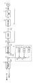
- the column shaft (steering shaft, handle shaft) 2 of the steering wheel 1 is a reduction gear 3 of the reduction mechanism, universal joints 4a and 4b, and a pinion rack mechanism 5
- the steering wheels 8L and 8R are connected to each other through tie rods 6a and 6b and further hub units 7a and 7b.
- the column shaft 2 is provided with a torque sensor 10 for detecting the steering torque of the steering wheel 1 and a steering angle sensor 14 for detecting the steering angle ⁇ , and the motor 20 for assisting the steering force of the steering wheel 1 is a reduction mechanism. It is connected to the column shaft 2 via a reduction gear (gear ratio n) 3.
- Electric power is supplied from the battery 13 to the control unit (ECU) 30 that controls the electric power steering device, and an ignition key signal is input through the ignition key 11.
- the control unit 30 calculates the current command value of the assist (steering assist) command based on the steering torque Th detected by the torque sensor 10 and the vehicle speed Vel detected by the vehicle speed sensor 12, and compensates for the current command value
- the current supplied to the motor 20 is controlled by the voltage control command value Vref that has been applied.
- the steering angle sensor 14 is not essential and may not be provided.
- the control unit 30 is connected with a CAN (Controller Area Network) 50 that transmits and receives various information of the vehicle, and the vehicle speed Vel can also be received from the CAN 50.
- the control unit 30 is also connected to a non-CAN 51 that transmits and receives communications other than the CAN 50, analog / digital signals, radio waves, and the like.
- the control unit 30 is mainly composed of a CPU (including an MPU, an MCU, etc.), and a typical function executed by a program inside the CPU is as shown in FIG.
- the steering torque Th detected by the torque sensor 10 and the vehicle speed Vel detected by the vehicle speed sensor 12 calculate a current command value Iref1. It is input to the section 31.
- the current command value calculation unit 31 calculates a current command value Iref1, which is a control target value of the current supplied to the motor 20, using an assist map or the like based on the input steering torque Th and the vehicle speed Vel.
- the current command value Iref1 is input to the current limiting unit 33 through the adding unit 32A, and the current command value Irefm whose maximum current is limited is input to the subtracting unit 32B, and a deviation I (Irefm) from the motor current value Im being fed back.
- the inverter circuit 37 uses an FET as a drive element, and is formed of a bridge circuit of FET.
- the compensation signal CM from the compensation signal generation unit 34 is added to the addition unit 32A, and the characteristic compensation of the steering system is performed by the addition of the compensation signal CM to improve convergence and inertia characteristics. ing.
- the compensation signal generation unit 34 adds the self aligning torque (SAT) 343 and the inertia 342 in the addition unit 344 and further adds the convergence property 341 to the addition result in the addition unit 345 and compensates the addition result of the addition unit 345 It is assumed that the signal CM.
- SAT self aligning torque
- the CPU microcomputer or the like of such an electric power steering apparatus generates a voltage control command value for controlling the motor by PI control as described above.
- the PI control gain is adjusted to an appropriate value for each type of vehicle.
- Patent Document 1 an electric power steering apparatus shown in Japanese Patent Laid-Open No. 2006-188183 (Patent Document 1) has been proposed. That is, the electric power steering apparatus of Patent Document 1 is provided with vibration detection means for detecting the vibration of the operation member, and when vibration of the operation member is detected by the vibration detection means, the proportional gain and integral gain of PI control And gain change means for reducing at least one of the two.
- the present invention has been made under the circumstances as described above, and the object of the present invention is to use the inertia or the torsion of the steering wheel based on the motor speed or the factor of the steering angle speed and the gear ratio without changing the gain of PI control.
- An object of the present invention is to provide an electric power steering apparatus in which steering wheel vibration (noise) caused by the spring property of a bar is suppressed and steering feeling is improved.
- the present invention relates to an electric power steering apparatus for driving a motor by an electric current command value calculated based on at least a steering torque to assist and control a steering, and the above object of the present invention is to A damping compensation unit for computing a damping compensation command value for suppressing the vibration of the steering wheel based on the factor (multiplied value) of the ratio is provided, and the current command value is corrected by the damping compensation command value. To be achieved.
- the object of the present invention is to provide a speed sensitive table 1 in which the vibration reduction compensation unit sets a trapezoidal vibration compensation value 1 before and after the multiplication value of the motor speed or steering angular velocity and gear ratio, and the vibration reduction compensation
- the BPF processing the value 1 by BP filtration and outputting the damping compensation value 2 or the damping compensation unit is composed of the speed sensitive table 2 according to the direction of the motor speed
- the vibration damping compensation value 3 is output from the speed sensitive table 2 or the vibration damping compensation unit further adds a gain 1 that is sensitive to the steering torque to the vibration damping compensation value 2 or 3.
- the vibration suppression compensation command value is calculated using the speed sensitive table and the BPF (band pass filter) based on the motor speed or steering angular velocity and the factor (multiplication value) of the gear ratio. Since the damping compensation command value is generated only at the time of steering reversal, it is possible to minimize the influence on other control and steering feeling.
- the electric power steering apparatus it is possible to reduce the steering wheel vibration due to the influence of the underbody resonance of the vehicle such as the brake judder and the shimmy without changing the gain of the PI control. It is possible to reduce steering wheel vibration due to transmission of force from the road surface to the steering system during traveling on a rough road, and steering wheel vibration due to other factors.
- the vibration (unusual noise) of the steering wheel due to the inertia of the steering wheel, the spring property of the torsion bar and the like is suppressed, and the vibration and the steering feeling which the driver feels unpleasant are improved.
- a table output value (vibration suppression compensation value 1) determined through a speed sensitive table corresponding to the motor speed is passed through a BPF (band pass filter) or a steering angle sensor.
- the steering angular velocity obtained by differentiating the detected steering angle ⁇ (or estimated steering angle) is determined, and the reduction gear ratio in the reduction mechanism is determined, and the steering angular velocity (differential component of steering angle ⁇ ) and gear
- the BPF is passed through a speed sensitive table according to the factor of the ratio (steering angular velocity x gear ratio).
- a damping compensation command value is calculated by multiplying the output value of the BPF (vibration compensation value 2) by the gain based on the steering torque and the gain based on the vehicle speed.
- the vibration compensation of the steering wheel is suppressed by subtracting the calculated damping compensation command value from the current command value for steering assistance and correcting it, and driving the motor with the corrected current command value.
- the factor of the steering angle speed ⁇ gear ratio corresponds to the motor speed ⁇ .
- the vibration control compensation command value is generated only at the time of steering reversal. And can minimize the influence on other control and steering feeling.
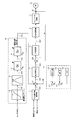
- FIG. 3 shows a configuration example (Embodiment 1) of the present invention corresponding to FIG. 2, and in the present invention, a vibration suppression compensation unit 40 is newly added, and the vibration suppression compensation unit 40 is added based on the motor speed ⁇ .
- the vibration suppression compensation command value VCc calculated in the above is subtracted and input to the addition / subtraction unit 32C to correct the current command value Iref1, thereby compensating for the vibration of the steering wheel. That is, in the present invention, the current command value Iref1 and the compensation signal CM are added to the adding / subtracting unit 32C, and the damping compensation command value VCc calculated by the damping compensation unit 40 is subtracted and input to the adding / subtracting unit 32C.
- the current command value Iref1 is corrected to obtain the current command value Iref2.
- the operation after the current command value Iref2 is completely the same as the case of FIG. 2 described above.
- the compensation by the compensation signal CM by the compensation signal generation unit 34 is not essential.
- the vibration reduction compensation unit 40 receives a motor velocity ⁇ , and outputs a trapezoidal vibration compensation value VC1 at around the motor velocity ⁇ zero, and a vibration compensation value VC1 from the velocity sensitivity table 41.
- Band-pass filtered BPF 42, torque sensitive gain unit 43 that multiplies damping compensation value VC2 from BPF 42 by gain Gt according to steering torque Th, and damping compensation value VC3 from torque sensitive gain unit 43 according to vehicle speed Vel It is composed of a vehicle speed sensitive gain section 44 which multiplies the gain Gv and outputs it as a damping compensation command value VCc.
- the torque sensitive gain unit 43 holds a constant gain Gt up to a predetermined torque value 1 (0.5 Nm in this example) with respect to the steering torque Th, as shown in FIG.
- the gain Gt increases up to 1.0 Nm, and the constant gain Gt is maintained at a predetermined torque value of 2 or more. That is, it is a characteristic that gradually increases from a certain torque (predetermined torque value 1) at a small value at low torque and saturates at a certain value (predetermined torque value 2). By doing this, the effect can be more easily obtained in the state where the steering wheel vibration is large (the steering torque at which the torsion angle is detected is large).
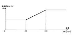
- the vehicle speed sensitive gain unit 44 holds a constant gain Gv up to a predetermined vehicle speed 1 (50 kph in this example) with respect to the vehicle speed Vel, and from a predetermined vehicle speed 1 to a predetermined vehicle speed 2 (100 kph in this example).
- the gain Gv is increased up to the point in which the constant gain Gv is maintained at a predetermined vehicle speed 2 or more. That is, it is a characteristic that gradually increases from a certain speed (predetermined vehicle speed 1) at a small value at low speed, and saturates at a certain value (predetermined vehicle speed 2). By doing this, in the vehicle speed state in which the steering wheel vibration easily occurs, the effect can be more easily obtained.
- the order of the torque sensitive gain unit 43 and the vehicle speed sensitive gain unit 44 may be reversed.
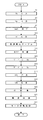
- the steering torque Th is input (step S1)
- the vehicle speed Vel is input (step S2)
- the current command value calculation unit 31 calculates the current command value Iref1 (step S3).
- damping compensation unit 40 inputs the motor speed ⁇ (step S10), and determines the damping compensation value VC1 according to the motor speed ⁇ by the speed sensitive table 41 (step S11).
- damping compensation value VC1 is input to BPF 42 to perform BP filtration processing (step S12), and damping compensation value VC2 subjected to BP filtering processing is input to torque sensitive gain unit 43, according to steering torque Th.
- the gain Gt is multiplied (step S13).
- Damping compensation value VC3 multiplied by gain Gt is input to vehicle speed sensitive gain unit 44 (step S14), multiplied by gain Gv according to vehicle speed Vel, and damping compensation command value VCc is output (step S15).
- the compensation signal generation unit 34 generates and outputs the compensation signal CM based on the convergence 341, the inertia 342 and the SAT 343 (step S20).
- step S3 The order of the calculation of the current command value Iref1 (steps S1 to S3), the calculation of the damping compensation command value VCc (steps S10 to S15), and the generation of the compensation signal CM (step S20) can be changed as appropriate.
- the current command value Iref1, the vibration control compensation command value VCc, and the compensation signal CM obtained as described above are input to the adding / subtracting unit 32C and subjected to addition / subtraction processing to generate a current command value Iref2 (step S30).
- the current command value Iref2 is limited by the current limiting unit 33 and then the current is controlled (step S31), and the motor 20 is driven and controlled (step S32).
- the motor speed ⁇ oscillates in a sine wave as shown in FIG. 7A.
- the speed sensitive table 41 has a trapezoidal wave shape around zero of the motor speed ⁇ . It has a characteristic of outputting a vibration suppression compensation value VC1. Therefore, the vibration reduction compensation value VC1 output from the speed sensitive table 41 has a trapezoidal wave shape shown in FIG. 7 (B).
- the vibration reduction compensation value VC1 from the speed sensitive table 41 is input to the BPF 42, and only the medium frequency component from which the high frequency component (for example, 20 Hz or more) and the low frequency component (for example, 5 Hz or less) is removed passes.
- the damping compensation value VC2 as shown in FIG.
- the motor speed ⁇ and the vibration control compensation value VC1 are obtained by subjecting the vibration control compensation value VC1 that is trapezoidal in the speed sensitive table 41 to band pass filtration processing with the BPF 42.
- the damping compensation value VC2 can be delayed (point t1) beyond the point t2 at which the zero cross occurs.
- the component of vibration suppression compensation value VC2 becomes a current command value (vibration suppression compensation command value VCc) for suppressing steering wheel vibration, and this vibration suppression compensation command value VCc is subtracted from the current command value Iref1 for steering.
- the vibration of the motor speed ⁇ can be delayed according to the timing when the motor speed ⁇ crosses zero, and as a result, the amplitude of the motor speed can be suppressed.
- FIG. 8 shows an example of the time response of the detection torque (proportional to the torsion bar torsion angle) when disturbance torque is applied by releasing the steering wheel in a state where the steering wheel vibration is easily generated.
- the characteristics with vibration compensation (this invention) and without vibration compensation (conventional) are compared.
- the torque / vehicle speed sensitive gain is a constant value. From the characteristic example of FIG. 8 as well, it can be seen that the vibration converges faster with the vibration damping compensation, and the vibration is suppressed.
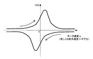
- the vibration suppression compensation unit 40 is configured of the speed sensitive table 41 and the BPF 42, but instead of the speed sensitive table 41 and the BPF 42, hysteresis corresponding to the direction of the motor speed ⁇ as shown in FIG.
- a speed sensitive table having characteristics may be used.
- the motor speed ⁇ is the input of the vibration reduction compensation in the above-described first embodiment
- the steering angular velocity is multiplied by the gear ratio of the speed reduction mechanism
- a value corresponding to the motor speed ⁇ is obtained. Therefore, the factors of the steering angular velocity and the gear ratio may be used as the input of the vibration reduction compensation.
- the steering angular velocity can be easily obtained by differentiating the steering angle from the steering angle sensor, and the gear ratio of the speed reduction mechanism is predetermined.
- the configuration of the case (embodiment 2) in which the factor of the steering angular velocity and the gear ratio is the vibration damping compensation input is as shown in the block diagram of FIG. 10 corresponding to FIG.
- the speed sensitive table 41A is sensitive to rudder angular velocity ⁇ gear ratio and has the same characteristics as the above-described speed sensitive table 41 (see FIG. 7), and the BPF 42, the torque sensitive table 43 and the vehicle speed sensitive table 44 are exactly the same as described above. .
- the compensation command value VCc from the damping compensation unit 40A is subtracted and input to the addition / subtraction unit 32C to correct the current command value Iref1, thereby compensating for the vibration of the steering wheel.
- the operation example of the case (embodiment 2) in which the factors of the steering angular velocity and the gear ratio are vibration damping compensation input is as shown in the flowchart of FIG. 11 corresponding to FIG. 6, and in this embodiment the rudder in step S10A.
- the angular velocity and the gear ratio determined in advance are input, and in step S11A, the vibration control compensation value VC1 according to the steering wheel angular velocity ⁇ gear ratio is determined by the speed sensitive table 41.
- the steering angular velocity may be determined by differentiating the steering angular velocity after inputting the steering angle ⁇ in step S10A.
- the same effect as that of the first embodiment can be obtained, and the characteristics shown in FIG. 8 can be obtained.
- vibration reduction compensation of the present invention may be combined with the function of detecting a vibration state.
- the torque sensitive gain Gt is not limited to the characteristic of FIG. 4 (e.g., non-linear increase), and the vehicle speed sensitive gain Gv is not limited to the characteristic of FIG. 5 (e.g., non-linear increase).
- Steering wheel 2 Column axis (steering shaft, steering wheel axis) 10 Torque sensor 12 Vehicle speed sensor 20 Motor 30 Control unit (ECU) 31 Current command value operation unit 33 Current limit unit 34 Compensation signal generation unit 35 PI control unit 36 PWM control unit 37 Inverter circuit 40, 40A Vibration compensation unit 41, 41A Speed sensitive table 42 BPF (band pass filter) 43 Torque sensitive gain unit 44 Vehicle speed sensitive gain unit 50 CAN
Landscapes
- Engineering & Computer Science (AREA)
- Chemical & Material Sciences (AREA)
- Combustion & Propulsion (AREA)
- Transportation (AREA)
- Mechanical Engineering (AREA)
- Steering Control In Accordance With Driving Conditions (AREA)
- Power Steering Mechanism (AREA)
Abstract
Priority Applications (4)
| Application Number | Priority Date | Filing Date | Title |
|---|---|---|---|
| JP2014545021A JP6065016B2 (ja) | 2013-04-23 | 2014-04-07 | 電動パワーステアリング装置 |
| US14/786,410 US9809246B2 (en) | 2013-04-23 | 2014-04-07 | Electric power steering apparatus |
| CN201480022961.0A CN105189254B (zh) | 2013-04-23 | 2014-04-07 | 电动助力转向装置 |
| EP14788897.8A EP2990302B1 (fr) | 2013-04-23 | 2014-04-07 | Dispositif de direction à assistance électrique |
Applications Claiming Priority (4)
| Application Number | Priority Date | Filing Date | Title |
|---|---|---|---|
| JP2013090650 | 2013-04-23 | ||
| JP2013-090650 | 2013-04-23 | ||
| JP2014075257 | 2014-04-01 | ||
| JP2014-075257 | 2014-04-01 |
Publications (1)
| Publication Number | Publication Date |
|---|---|
| WO2014175052A1 true WO2014175052A1 (fr) | 2014-10-30 |
Family
ID=51791633
Family Applications (1)
| Application Number | Title | Priority Date | Filing Date |
|---|---|---|---|
| PCT/JP2014/060093 WO2014175052A1 (fr) | 2013-04-23 | 2014-04-07 | Dispositif de direction a assistance electrique |
Country Status (5)
| Country | Link |
|---|---|
| US (1) | US9809246B2 (fr) |
| EP (1) | EP2990302B1 (fr) |
| JP (1) | JP6065016B2 (fr) |
| CN (1) | CN105189254B (fr) |
| WO (1) | WO2014175052A1 (fr) |
Cited By (6)
| Publication number | Priority date | Publication date | Assignee | Title |
|---|---|---|---|---|
| CN105984462A (zh) * | 2015-03-21 | 2016-10-05 | 丰田自动车株式会社 | 振动控制装置和振动控制系统 |
| JP2017210009A (ja) * | 2016-05-23 | 2017-11-30 | 日本精工株式会社 | 電動パワーステアリング装置 |
| KR20180080400A (ko) * | 2017-01-02 | 2018-07-12 | 현대모비스 주식회사 | 전동식 동력 조향장치의 댐핑 제어 장치 및 그 방법 |
| WO2018168891A1 (fr) * | 2017-03-16 | 2018-09-20 | 日本精工株式会社 | Dispositif de direction assistée électrique |
| EP3254933A4 (fr) * | 2015-02-04 | 2018-11-14 | NSK Ltd. | Dispositif de direction assistée électrique |
| CN111976824A (zh) * | 2019-05-21 | 2020-11-24 | 上海汽车集团股份有限公司 | 电动助力转向系统的惯量补偿方法及相关装置 |
Families Citing this family (11)
| Publication number | Priority date | Publication date | Assignee | Title |
|---|---|---|---|---|
| JP6058214B2 (ja) * | 2014-04-25 | 2017-01-11 | 三菱電機株式会社 | 操舵制御装置およびその操舵補助トルク制御方法 |
| US10579232B2 (en) * | 2014-07-30 | 2020-03-03 | Metra Electronics Corporation | Touchscreen-based vehicle interface |
| KR101684513B1 (ko) * | 2015-04-28 | 2016-12-08 | 현대자동차 주식회사 | Mdps 시스템의 복원 제어장치 |
| EP3446947A4 (fr) * | 2016-07-06 | 2020-03-25 | NSK Ltd. | Dispositif de direction assistée électrique |
| JP6631440B2 (ja) * | 2016-08-25 | 2020-01-15 | 株式会社デンソー | 操舵制御装置 |
| KR102516689B1 (ko) * | 2016-09-07 | 2023-04-03 | 현대모비스 주식회사 | 전동식 파워 스티어링 시스템의 컬럼토크 보상 장치 및 방법 |
| DE102017121952A1 (de) * | 2017-09-21 | 2019-03-21 | Trw Automotive Gmbh | Verfahren zum Erkennen von Störgrößen in einem Lenkungssystem sowie Lenkungssystem für ein Kraftfahrzeug |
| US10549773B2 (en) * | 2017-12-13 | 2020-02-04 | Gm Global Technology Operations, Llc | Anti-loss-of-assistance for electric motor |
| US11511795B2 (en) * | 2018-10-11 | 2022-11-29 | Steering Solutions Ip Holding Corporation | Dither noise management in electric power steering systems |
| CN112298341B (zh) * | 2019-07-30 | 2022-03-15 | 比亚迪股份有限公司 | 车辆及其电动助力转向系统的控制方法、控制装置 |
| EP4052993B1 (fr) * | 2020-10-21 | 2023-09-13 | NSK Ltd. | Dispositif de commande et dispositif de direction assistée électrique |
Citations (9)
| Publication number | Priority date | Publication date | Assignee | Title |
|---|---|---|---|---|
| JPH0728527A (ja) * | 1993-07-12 | 1995-01-31 | Fanuc Ltd | クーロン摩擦の補正処理方法 |
| JPH10310072A (ja) * | 1997-05-09 | 1998-11-24 | Kayaba Ind Co Ltd | 電動式パワーステアリングシステム |
| JP2003212142A (ja) * | 2002-01-21 | 2003-07-30 | Hitachi Unisia Automotive Ltd | 電動パワーステアリング装置 |
| JP2005262936A (ja) * | 2004-03-17 | 2005-09-29 | Hitachi Ltd | 電動パワーステアリング装置 |
| JP2006188183A (ja) | 2005-01-07 | 2006-07-20 | Favess Co Ltd | 電動パワーステアリング装置 |
| JP2006335228A (ja) * | 2005-06-02 | 2006-12-14 | Mitsubishi Electric Corp | 電動パワーステアリング制御装置 |
| JP2009280163A (ja) * | 2008-05-26 | 2009-12-03 | Mitsubishi Electric Corp | 電動パワーステアリング制御装置 |
| WO2011052470A1 (fr) * | 2009-10-30 | 2011-05-05 | 三菱電機株式会社 | Dispositif de commande de direction assistée électrique |
| JP2011121383A (ja) * | 2009-12-08 | 2011-06-23 | Mitsubishi Electric Corp | 電動パワーステアリング制御装置 |
Family Cites Families (10)
| Publication number | Priority date | Publication date | Assignee | Title |
|---|---|---|---|---|
| JP3712876B2 (ja) | 1998-12-01 | 2005-11-02 | 三菱電機株式会社 | 電動式パワーステアリング制御装置 |
| JP4525306B2 (ja) * | 2004-11-12 | 2010-08-18 | 株式会社ジェイテクト | 電動パワーステアリング装置 |
| US7523806B2 (en) | 2005-09-20 | 2009-04-28 | Delphi Technologies, Inc | Method and system for improved active damping of steering systems |
| JP4468415B2 (ja) | 2007-06-29 | 2010-05-26 | 三菱電機株式会社 | 電動パワーステアリング制御装置 |
| WO2009078074A1 (fr) | 2007-12-14 | 2009-06-25 | Mitsubishi Electric Corporation | Dispositif de commande pour direction assistée électrique |
| JP2009269540A (ja) | 2008-05-09 | 2009-11-19 | Jtekt Corp | 電動パワーステアリング装置 |
| JP5293738B2 (ja) | 2009-01-13 | 2013-09-18 | トヨタ自動車株式会社 | 車両の制御装置 |
| US8290656B2 (en) | 2009-05-25 | 2012-10-16 | Nissan Motor Co., Ltd. | Controller and controlling method of electric vehicle |
| JP5642272B2 (ja) * | 2011-05-25 | 2014-12-17 | 三菱電機株式会社 | 電動パワーステアリングの制御装置 |
| KR20150066551A (ko) * | 2012-11-05 | 2015-06-16 | 도요타 지도샤(주) | 조타 제어 장치 |
-
2014
- 2014-04-07 WO PCT/JP2014/060093 patent/WO2014175052A1/fr active Application Filing
- 2014-04-07 JP JP2014545021A patent/JP6065016B2/ja not_active Expired - Fee Related
- 2014-04-07 EP EP14788897.8A patent/EP2990302B1/fr active Active
- 2014-04-07 US US14/786,410 patent/US9809246B2/en not_active Expired - Fee Related
- 2014-04-07 CN CN201480022961.0A patent/CN105189254B/zh not_active Expired - Fee Related
Patent Citations (9)
| Publication number | Priority date | Publication date | Assignee | Title |
|---|---|---|---|---|
| JPH0728527A (ja) * | 1993-07-12 | 1995-01-31 | Fanuc Ltd | クーロン摩擦の補正処理方法 |
| JPH10310072A (ja) * | 1997-05-09 | 1998-11-24 | Kayaba Ind Co Ltd | 電動式パワーステアリングシステム |
| JP2003212142A (ja) * | 2002-01-21 | 2003-07-30 | Hitachi Unisia Automotive Ltd | 電動パワーステアリング装置 |
| JP2005262936A (ja) * | 2004-03-17 | 2005-09-29 | Hitachi Ltd | 電動パワーステアリング装置 |
| JP2006188183A (ja) | 2005-01-07 | 2006-07-20 | Favess Co Ltd | 電動パワーステアリング装置 |
| JP2006335228A (ja) * | 2005-06-02 | 2006-12-14 | Mitsubishi Electric Corp | 電動パワーステアリング制御装置 |
| JP2009280163A (ja) * | 2008-05-26 | 2009-12-03 | Mitsubishi Electric Corp | 電動パワーステアリング制御装置 |
| WO2011052470A1 (fr) * | 2009-10-30 | 2011-05-05 | 三菱電機株式会社 | Dispositif de commande de direction assistée électrique |
| JP2011121383A (ja) * | 2009-12-08 | 2011-06-23 | Mitsubishi Electric Corp | 電動パワーステアリング制御装置 |
Cited By (13)
| Publication number | Priority date | Publication date | Assignee | Title |
|---|---|---|---|---|
| EP3254933A4 (fr) * | 2015-02-04 | 2018-11-14 | NSK Ltd. | Dispositif de direction assistée électrique |
| KR101853822B1 (ko) * | 2015-03-21 | 2018-05-04 | 도요타 지도샤(주) | 제진 제어 장치 및 제진 제어 시스템 |
| CN105984462A (zh) * | 2015-03-21 | 2016-10-05 | 丰田自动车株式会社 | 振动控制装置和振动控制系统 |
| US10023192B2 (en) | 2015-03-21 | 2018-07-17 | Toyota Jidosha Kabushiki Kaisha | Vibration control device and vibration control system |
| JP2017210009A (ja) * | 2016-05-23 | 2017-11-30 | 日本精工株式会社 | 電動パワーステアリング装置 |
| KR20180080400A (ko) * | 2017-01-02 | 2018-07-12 | 현대모비스 주식회사 | 전동식 동력 조향장치의 댐핑 제어 장치 및 그 방법 |
| KR102228161B1 (ko) | 2017-01-02 | 2021-03-17 | 현대모비스 주식회사 | 전동식 동력 조향장치의 댐핑 제어 장치 및 그 방법 |
| WO2018168891A1 (fr) * | 2017-03-16 | 2018-09-20 | 日本精工株式会社 | Dispositif de direction assistée électrique |
| JPWO2018168891A1 (ja) * | 2017-03-16 | 2019-06-27 | 日本精工株式会社 | 電動パワーステアリング装置 |
| US10661825B2 (en) | 2017-03-16 | 2020-05-26 | Nsk Ltd. | Electric power steering apparatus |
| CN111406011A (zh) * | 2017-03-16 | 2020-07-10 | 日本精工株式会社 | 电动助力转向装置 |
| CN111976824A (zh) * | 2019-05-21 | 2020-11-24 | 上海汽车集团股份有限公司 | 电动助力转向系统的惯量补偿方法及相关装置 |
| CN111976824B (zh) * | 2019-05-21 | 2021-11-16 | 上海汽车集团股份有限公司 | 电动助力转向系统的惯量补偿方法及相关装置 |
Also Published As
| Publication number | Publication date |
|---|---|
| CN105189254A (zh) | 2015-12-23 |
| EP2990302A1 (fr) | 2016-03-02 |
| US20160059885A1 (en) | 2016-03-03 |
| EP2990302B1 (fr) | 2020-05-06 |
| EP2990302A4 (fr) | 2017-05-24 |
| US9809246B2 (en) | 2017-11-07 |
| CN105189254B (zh) | 2017-08-15 |
| JP6065016B2 (ja) | 2017-01-25 |
| JPWO2014175052A1 (ja) | 2017-02-23 |
Similar Documents
| Publication | Publication Date | Title |
|---|---|---|
| WO2014175052A1 (fr) | Dispositif de direction a assistance electrique | |
| US10099721B2 (en) | Electric power steering apparatus | |
| JP6504322B2 (ja) | 電動パワーステアリング装置 | |
| US9637166B2 (en) | Electric power steering apparatus | |
| WO2016027663A1 (fr) | Dispositif de direction à assistance électrique | |
| EP1990257B1 (fr) | Appareil de direction assistée électrique | |
| WO2019193976A1 (fr) | Dispositif de direction de véhicule | |
| WO2016017234A1 (fr) | Dispositif de direction à assistance électrique | |
| WO2016051884A1 (fr) | Dispositif de direction assistée électrique | |
| JP2017210009A (ja) | 電動パワーステアリング装置 | |
| JP6020776B2 (ja) | 電動パワーステアリング装置 | |
| JP6590090B2 (ja) | 電動パワーステアリング装置 | |
| JP5994959B2 (ja) | 電動パワーステアリング装置 | |
| JP6702513B2 (ja) | 車両用操向装置 | |
| WO2020145036A1 (fr) | Dispositif de direction de véhicule | |
| EP3132996B1 (fr) | Dispositif de direction à assistance électrique | |
| WO2020100411A1 (fr) | Dispositif de direction de véhicule | |
| WO2019167661A1 (fr) | Dispositif de direction de véhicule | |
| WO2020213285A1 (fr) | Appareil de direction de véhicule | |
| JP2009248838A (ja) | 電動パワーステアリング装置の制御装置 | |
| WO2020183838A1 (fr) | Dispositif de direction de véhicule |
Legal Events
| Date | Code | Title | Description |
|---|---|---|---|
| WWE | Wipo information: entry into national phase |
Ref document number: 201480022961.0 Country of ref document: CN |
|
| ENP | Entry into the national phase |
Ref document number: 2014545021 Country of ref document: JP Kind code of ref document: A |
|
| 121 | Ep: the epo has been informed by wipo that ep was designated in this application |
Ref document number: 14788897 Country of ref document: EP Kind code of ref document: A1 |
|
| WWE | Wipo information: entry into national phase |
Ref document number: 14786410 Country of ref document: US |
|
| NENP | Non-entry into the national phase |
Ref country code: DE |
|
| WWE | Wipo information: entry into national phase |
Ref document number: 2014788897 Country of ref document: EP |