WO2014174820A1 - 船舶用二重殻タンク構造および液化ガス運搬船 - Google Patents
船舶用二重殻タンク構造および液化ガス運搬船 Download PDFInfo
- Publication number
- WO2014174820A1 WO2014174820A1 PCT/JP2014/002222 JP2014002222W WO2014174820A1 WO 2014174820 A1 WO2014174820 A1 WO 2014174820A1 JP 2014002222 W JP2014002222 W JP 2014002222W WO 2014174820 A1 WO2014174820 A1 WO 2014174820A1
- Authority
- WO
- WIPO (PCT)
- Prior art keywords
- tank
- cylindrical body
- double
- shell
- peripheral surface
- Prior art date
- Legal status (The legal status is an assumption and is not a legal conclusion. Google has not performed a legal analysis and makes no representation as to the accuracy of the status listed.)
- Ceased
Links
Images


Classifications
-
- B—PERFORMING OPERATIONS; TRANSPORTING
- B63—SHIPS OR OTHER WATERBORNE VESSELS; RELATED EQUIPMENT
- B63B—SHIPS OR OTHER WATERBORNE VESSELS; EQUIPMENT FOR SHIPPING
- B63B35/00—Vessels or similar floating structures specially adapted for specific purposes and not otherwise provided for
- B63B35/003—Vessels or similar floating structures specially adapted for specific purposes and not otherwise provided for for transporting very large loads, e.g. offshore structure modules
-
- B—PERFORMING OPERATIONS; TRANSPORTING
- B63—SHIPS OR OTHER WATERBORNE VESSELS; RELATED EQUIPMENT
- B63B—SHIPS OR OTHER WATERBORNE VESSELS; EQUIPMENT FOR SHIPPING
- B63B25/00—Load-accommodating arrangements, e.g. stowing, trimming; Vessels characterised thereby
- B63B25/02—Load-accommodating arrangements, e.g. stowing, trimming; Vessels characterised thereby for bulk goods
- B63B25/08—Load-accommodating arrangements, e.g. stowing, trimming; Vessels characterised thereby for bulk goods fluid
- B63B25/12—Load-accommodating arrangements, e.g. stowing, trimming; Vessels characterised thereby for bulk goods fluid closed
- B63B25/16—Load-accommodating arrangements, e.g. stowing, trimming; Vessels characterised thereby for bulk goods fluid closed heat-insulated
-
- B—PERFORMING OPERATIONS; TRANSPORTING
- B63—SHIPS OR OTHER WATERBORNE VESSELS; RELATED EQUIPMENT
- B63B—SHIPS OR OTHER WATERBORNE VESSELS; EQUIPMENT FOR SHIPPING
- B63B3/00—Hulls characterised by their structure or component parts
- B63B3/14—Hull parts
- B63B3/16—Shells
-
- F—MECHANICAL ENGINEERING; LIGHTING; HEATING; WEAPONS; BLASTING
- F17—STORING OR DISTRIBUTING GASES OR LIQUIDS
- F17C—VESSELS FOR CONTAINING OR STORING COMPRESSED, LIQUEFIED OR SOLIDIFIED GASES; FIXED-CAPACITY GAS-HOLDERS; FILLING VESSELS WITH, OR DISCHARGING FROM VESSELS, COMPRESSED, LIQUEFIED, OR SOLIDIFIED GASES
- F17C13/00—Details of vessels or of the filling or discharging of vessels
- F17C13/08—Mounting arrangements for vessels
- F17C13/082—Mounting arrangements for vessels for large sea-borne storage vessels
-
- F—MECHANICAL ENGINEERING; LIGHTING; HEATING; WEAPONS; BLASTING
- F17—STORING OR DISTRIBUTING GASES OR LIQUIDS
- F17C—VESSELS FOR CONTAINING OR STORING COMPRESSED, LIQUEFIED OR SOLIDIFIED GASES; FIXED-CAPACITY GAS-HOLDERS; FILLING VESSELS WITH, OR DISCHARGING FROM VESSELS, COMPRESSED, LIQUEFIED, OR SOLIDIFIED GASES
- F17C3/00—Vessels not under pressure
- F17C3/02—Vessels not under pressure with provision for thermal insulation
- F17C3/025—Bulk storage in barges or on ships
-
- F—MECHANICAL ENGINEERING; LIGHTING; HEATING; WEAPONS; BLASTING
- F17—STORING OR DISTRIBUTING GASES OR LIQUIDS
- F17C—VESSELS FOR CONTAINING OR STORING COMPRESSED, LIQUEFIED OR SOLIDIFIED GASES; FIXED-CAPACITY GAS-HOLDERS; FILLING VESSELS WITH, OR DISCHARGING FROM VESSELS, COMPRESSED, LIQUEFIED, OR SOLIDIFIED GASES
- F17C2201/00—Vessel construction, in particular geometry, arrangement or size
- F17C2201/01—Shape
- F17C2201/0104—Shape cylindrical
- F17C2201/0109—Shape cylindrical with exteriorly curved end-piece
-
- F—MECHANICAL ENGINEERING; LIGHTING; HEATING; WEAPONS; BLASTING
- F17—STORING OR DISTRIBUTING GASES OR LIQUIDS
- F17C—VESSELS FOR CONTAINING OR STORING COMPRESSED, LIQUEFIED OR SOLIDIFIED GASES; FIXED-CAPACITY GAS-HOLDERS; FILLING VESSELS WITH, OR DISCHARGING FROM VESSELS, COMPRESSED, LIQUEFIED, OR SOLIDIFIED GASES
- F17C2201/00—Vessel construction, in particular geometry, arrangement or size
- F17C2201/03—Orientation
- F17C2201/035—Orientation with substantially horizontal main axis
-
- F—MECHANICAL ENGINEERING; LIGHTING; HEATING; WEAPONS; BLASTING
- F17—STORING OR DISTRIBUTING GASES OR LIQUIDS
- F17C—VESSELS FOR CONTAINING OR STORING COMPRESSED, LIQUEFIED OR SOLIDIFIED GASES; FIXED-CAPACITY GAS-HOLDERS; FILLING VESSELS WITH, OR DISCHARGING FROM VESSELS, COMPRESSED, LIQUEFIED, OR SOLIDIFIED GASES
- F17C2201/00—Vessel construction, in particular geometry, arrangement or size
- F17C2201/05—Size
- F17C2201/052—Size large (>1000 m3)
-
- F—MECHANICAL ENGINEERING; LIGHTING; HEATING; WEAPONS; BLASTING
- F17—STORING OR DISTRIBUTING GASES OR LIQUIDS
- F17C—VESSELS FOR CONTAINING OR STORING COMPRESSED, LIQUEFIED OR SOLIDIFIED GASES; FIXED-CAPACITY GAS-HOLDERS; FILLING VESSELS WITH, OR DISCHARGING FROM VESSELS, COMPRESSED, LIQUEFIED, OR SOLIDIFIED GASES
- F17C2201/00—Vessel construction, in particular geometry, arrangement or size
- F17C2201/05—Size
- F17C2201/054—Size medium (>1 m3)
-
- F—MECHANICAL ENGINEERING; LIGHTING; HEATING; WEAPONS; BLASTING
- F17—STORING OR DISTRIBUTING GASES OR LIQUIDS
- F17C—VESSELS FOR CONTAINING OR STORING COMPRESSED, LIQUEFIED OR SOLIDIFIED GASES; FIXED-CAPACITY GAS-HOLDERS; FILLING VESSELS WITH, OR DISCHARGING FROM VESSELS, COMPRESSED, LIQUEFIED, OR SOLIDIFIED GASES
- F17C2203/00—Vessel construction, in particular walls or details thereof
- F17C2203/01—Reinforcing or suspension means
- F17C2203/011—Reinforcing means
- F17C2203/013—Reinforcing means in the vessel, e.g. columns
-
- F—MECHANICAL ENGINEERING; LIGHTING; HEATING; WEAPONS; BLASTING
- F17—STORING OR DISTRIBUTING GASES OR LIQUIDS
- F17C—VESSELS FOR CONTAINING OR STORING COMPRESSED, LIQUEFIED OR SOLIDIFIED GASES; FIXED-CAPACITY GAS-HOLDERS; FILLING VESSELS WITH, OR DISCHARGING FROM VESSELS, COMPRESSED, LIQUEFIED, OR SOLIDIFIED GASES
- F17C2203/00—Vessel construction, in particular walls or details thereof
- F17C2203/01—Reinforcing or suspension means
- F17C2203/014—Suspension means
-
- F—MECHANICAL ENGINEERING; LIGHTING; HEATING; WEAPONS; BLASTING
- F17—STORING OR DISTRIBUTING GASES OR LIQUIDS
- F17C—VESSELS FOR CONTAINING OR STORING COMPRESSED, LIQUEFIED OR SOLIDIFIED GASES; FIXED-CAPACITY GAS-HOLDERS; FILLING VESSELS WITH, OR DISCHARGING FROM VESSELS, COMPRESSED, LIQUEFIED, OR SOLIDIFIED GASES
- F17C2203/00—Vessel construction, in particular walls or details thereof
- F17C2203/03—Thermal insulations
- F17C2203/0304—Thermal insulations by solid means
-
- F—MECHANICAL ENGINEERING; LIGHTING; HEATING; WEAPONS; BLASTING
- F17—STORING OR DISTRIBUTING GASES OR LIQUIDS
- F17C—VESSELS FOR CONTAINING OR STORING COMPRESSED, LIQUEFIED OR SOLIDIFIED GASES; FIXED-CAPACITY GAS-HOLDERS; FILLING VESSELS WITH, OR DISCHARGING FROM VESSELS, COMPRESSED, LIQUEFIED, OR SOLIDIFIED GASES
- F17C2203/00—Vessel construction, in particular walls or details thereof
- F17C2203/03—Thermal insulations
- F17C2203/0391—Thermal insulations by vacuum
-
- F—MECHANICAL ENGINEERING; LIGHTING; HEATING; WEAPONS; BLASTING
- F17—STORING OR DISTRIBUTING GASES OR LIQUIDS
- F17C—VESSELS FOR CONTAINING OR STORING COMPRESSED, LIQUEFIED OR SOLIDIFIED GASES; FIXED-CAPACITY GAS-HOLDERS; FILLING VESSELS WITH, OR DISCHARGING FROM VESSELS, COMPRESSED, LIQUEFIED, OR SOLIDIFIED GASES
- F17C2203/00—Vessel construction, in particular walls or details thereof
- F17C2203/06—Materials for walls or layers thereof; Properties or structures of walls or their materials
- F17C2203/0602—Wall structures; Special features thereof
- F17C2203/0612—Wall structures
- F17C2203/0626—Multiple walls
- F17C2203/0629—Two walls
-
- F—MECHANICAL ENGINEERING; LIGHTING; HEATING; WEAPONS; BLASTING
- F17—STORING OR DISTRIBUTING GASES OR LIQUIDS
- F17C—VESSELS FOR CONTAINING OR STORING COMPRESSED, LIQUEFIED OR SOLIDIFIED GASES; FIXED-CAPACITY GAS-HOLDERS; FILLING VESSELS WITH, OR DISCHARGING FROM VESSELS, COMPRESSED, LIQUEFIED, OR SOLIDIFIED GASES
- F17C2203/00—Vessel construction, in particular walls or details thereof
- F17C2203/06—Materials for walls or layers thereof; Properties or structures of walls or their materials
- F17C2203/0634—Materials for walls or layers thereof
- F17C2203/0636—Metals
-
- F—MECHANICAL ENGINEERING; LIGHTING; HEATING; WEAPONS; BLASTING
- F17—STORING OR DISTRIBUTING GASES OR LIQUIDS
- F17C—VESSELS FOR CONTAINING OR STORING COMPRESSED, LIQUEFIED OR SOLIDIFIED GASES; FIXED-CAPACITY GAS-HOLDERS; FILLING VESSELS WITH, OR DISCHARGING FROM VESSELS, COMPRESSED, LIQUEFIED, OR SOLIDIFIED GASES
- F17C2205/00—Vessel construction, in particular mounting arrangements, attachments or identifications means
- F17C2205/01—Mounting arrangements
- F17C2205/0103—Exterior arrangements
-
- F—MECHANICAL ENGINEERING; LIGHTING; HEATING; WEAPONS; BLASTING
- F17—STORING OR DISTRIBUTING GASES OR LIQUIDS
- F17C—VESSELS FOR CONTAINING OR STORING COMPRESSED, LIQUEFIED OR SOLIDIFIED GASES; FIXED-CAPACITY GAS-HOLDERS; FILLING VESSELS WITH, OR DISCHARGING FROM VESSELS, COMPRESSED, LIQUEFIED, OR SOLIDIFIED GASES
- F17C2205/00—Vessel construction, in particular mounting arrangements, attachments or identifications means
- F17C2205/01—Mounting arrangements
- F17C2205/0153—Details of mounting arrangements
- F17C2205/018—Supporting feet
-
- F—MECHANICAL ENGINEERING; LIGHTING; HEATING; WEAPONS; BLASTING
- F17—STORING OR DISTRIBUTING GASES OR LIQUIDS
- F17C—VESSELS FOR CONTAINING OR STORING COMPRESSED, LIQUEFIED OR SOLIDIFIED GASES; FIXED-CAPACITY GAS-HOLDERS; FILLING VESSELS WITH, OR DISCHARGING FROM VESSELS, COMPRESSED, LIQUEFIED, OR SOLIDIFIED GASES
- F17C2221/00—Handled fluid, in particular type of fluid
- F17C2221/01—Pure fluids
- F17C2221/012—Hydrogen
-
- F—MECHANICAL ENGINEERING; LIGHTING; HEATING; WEAPONS; BLASTING
- F17—STORING OR DISTRIBUTING GASES OR LIQUIDS
- F17C—VESSELS FOR CONTAINING OR STORING COMPRESSED, LIQUEFIED OR SOLIDIFIED GASES; FIXED-CAPACITY GAS-HOLDERS; FILLING VESSELS WITH, OR DISCHARGING FROM VESSELS, COMPRESSED, LIQUEFIED, OR SOLIDIFIED GASES
- F17C2221/00—Handled fluid, in particular type of fluid
- F17C2221/03—Mixtures
- F17C2221/032—Hydrocarbons
- F17C2221/033—Methane, e.g. natural gas, CNG, LNG, GNL, GNC, PLNG
-
- F—MECHANICAL ENGINEERING; LIGHTING; HEATING; WEAPONS; BLASTING
- F17—STORING OR DISTRIBUTING GASES OR LIQUIDS
- F17C—VESSELS FOR CONTAINING OR STORING COMPRESSED, LIQUEFIED OR SOLIDIFIED GASES; FIXED-CAPACITY GAS-HOLDERS; FILLING VESSELS WITH, OR DISCHARGING FROM VESSELS, COMPRESSED, LIQUEFIED, OR SOLIDIFIED GASES
- F17C2221/00—Handled fluid, in particular type of fluid
- F17C2221/03—Mixtures
- F17C2221/032—Hydrocarbons
- F17C2221/035—Propane butane, e.g. LPG, GPL
-
- F—MECHANICAL ENGINEERING; LIGHTING; HEATING; WEAPONS; BLASTING
- F17—STORING OR DISTRIBUTING GASES OR LIQUIDS
- F17C—VESSELS FOR CONTAINING OR STORING COMPRESSED, LIQUEFIED OR SOLIDIFIED GASES; FIXED-CAPACITY GAS-HOLDERS; FILLING VESSELS WITH, OR DISCHARGING FROM VESSELS, COMPRESSED, LIQUEFIED, OR SOLIDIFIED GASES
- F17C2223/00—Handled fluid before transfer, i.e. state of fluid when stored in the vessel or before transfer from the vessel
- F17C2223/01—Handled fluid before transfer, i.e. state of fluid when stored in the vessel or before transfer from the vessel characterised by the phase
- F17C2223/0146—Two-phase
- F17C2223/0153—Liquefied gas, e.g. LPG, GPL
- F17C2223/0161—Liquefied gas, e.g. LPG, GPL cryogenic, e.g. LNG, GNL, PLNG
-
- F—MECHANICAL ENGINEERING; LIGHTING; HEATING; WEAPONS; BLASTING
- F17—STORING OR DISTRIBUTING GASES OR LIQUIDS
- F17C—VESSELS FOR CONTAINING OR STORING COMPRESSED, LIQUEFIED OR SOLIDIFIED GASES; FIXED-CAPACITY GAS-HOLDERS; FILLING VESSELS WITH, OR DISCHARGING FROM VESSELS, COMPRESSED, LIQUEFIED, OR SOLIDIFIED GASES
- F17C2223/00—Handled fluid before transfer, i.e. state of fluid when stored in the vessel or before transfer from the vessel
- F17C2223/03—Handled fluid before transfer, i.e. state of fluid when stored in the vessel or before transfer from the vessel characterised by the pressure level
- F17C2223/033—Small pressure, e.g. for liquefied gas
-
- F—MECHANICAL ENGINEERING; LIGHTING; HEATING; WEAPONS; BLASTING
- F17—STORING OR DISTRIBUTING GASES OR LIQUIDS
- F17C—VESSELS FOR CONTAINING OR STORING COMPRESSED, LIQUEFIED OR SOLIDIFIED GASES; FIXED-CAPACITY GAS-HOLDERS; FILLING VESSELS WITH, OR DISCHARGING FROM VESSELS, COMPRESSED, LIQUEFIED, OR SOLIDIFIED GASES
- F17C2260/00—Purposes of gas storage and gas handling
- F17C2260/01—Improving mechanical properties or manufacturing
- F17C2260/011—Improving strength
-
- F—MECHANICAL ENGINEERING; LIGHTING; HEATING; WEAPONS; BLASTING
- F17—STORING OR DISTRIBUTING GASES OR LIQUIDS
- F17C—VESSELS FOR CONTAINING OR STORING COMPRESSED, LIQUEFIED OR SOLIDIFIED GASES; FIXED-CAPACITY GAS-HOLDERS; FILLING VESSELS WITH, OR DISCHARGING FROM VESSELS, COMPRESSED, LIQUEFIED, OR SOLIDIFIED GASES
- F17C2260/00—Purposes of gas storage and gas handling
- F17C2260/03—Dealing with losses
- F17C2260/031—Dealing with losses due to heat transfer
-
- F—MECHANICAL ENGINEERING; LIGHTING; HEATING; WEAPONS; BLASTING
- F17—STORING OR DISTRIBUTING GASES OR LIQUIDS
- F17C—VESSELS FOR CONTAINING OR STORING COMPRESSED, LIQUEFIED OR SOLIDIFIED GASES; FIXED-CAPACITY GAS-HOLDERS; FILLING VESSELS WITH, OR DISCHARGING FROM VESSELS, COMPRESSED, LIQUEFIED, OR SOLIDIFIED GASES
- F17C2270/00—Applications
- F17C2270/01—Applications for fluid transport or storage
- F17C2270/0102—Applications for fluid transport or storage on or in the water
- F17C2270/0105—Ships
-
- Y—GENERAL TAGGING OF NEW TECHNOLOGICAL DEVELOPMENTS; GENERAL TAGGING OF CROSS-SECTIONAL TECHNOLOGIES SPANNING OVER SEVERAL SECTIONS OF THE IPC; TECHNICAL SUBJECTS COVERED BY FORMER USPC CROSS-REFERENCE ART COLLECTIONS [XRACs] AND DIGESTS
- Y02—TECHNOLOGIES OR APPLICATIONS FOR MITIGATION OR ADAPTATION AGAINST CLIMATE CHANGE
- Y02E—REDUCTION OF GREENHOUSE GAS [GHG] EMISSIONS, RELATED TO ENERGY GENERATION, TRANSMISSION OR DISTRIBUTION
- Y02E60/00—Enabling technologies; Technologies with a potential or indirect contribution to GHG emissions mitigation
- Y02E60/30—Hydrogen technology
- Y02E60/32—Hydrogen storage
Definitions
- the present invention relates to a structure of a double shell tank mounted on a ship, and a liquefied gas carrier ship equipped with a double shell tank having the tank structure.
- LNG tanks of various shapes are used in liquefied gas carriers for transporting liquefied gas by sea.
- the horizontally placed cylindrical tank may be supported by a pair of saddles that are separated from each other in the axial direction of the tank.
- the saddle has an arc-shaped support surface along the outer peripheral surface of the tank so that it can receive the load of the tank even when the ship shakes (rolling when the axial direction of the tank coincides with the ship length direction). ing.
- Patent Document 1 discloses a double-shell tank in which an outer tub is supported by a pair of saddles, and two support portions are arranged on each saddle between the outer tub and the inner tub. ing.
- each support part on each saddle are arranged symmetrically with respect to the vertical line passing through the center of the tank, and have a configuration in which a plurality of plate-like members are stacked in the radial direction of the tank.
- each support part is interposed between the outer tank side support member disposed on the inner peripheral surface of the outer tank, the inner tank side support member disposed on the outer peripheral surface of the inner tank, and the like. It consists of a heat insulating material.
- Patent Document 2 discloses a vertical cylindrical triple-shell tank in which an intermediate shield plate is provided between an inner tank and an outer tank as a conventional technique.
- a support device is disposed between the outer tank and the inner tank.
- This support device includes an outer tubular body made of GFRP that connects the outer tank and the intermediate shield plate, an inner tubular body made of CFRP that has a smaller diameter than the outer tubular body, and that connects the intermediate shield plate and the inner tank.
- a cup-shaped holding portion for integrally holding the inner cylindrical body in the outer cylindrical body, which is provided integrally with the intermediate shield plate.
- this support device is for supporting the weight of the inner tank in a vertically installed cylindrical tank at one point of a downward hemispherical apex where the weight of the inner tank is concentrated. It cannot be applied to a horizontal cylindrical tank supported by a saddle.
- Japanese Patent Laid-Open No. 60-245899 discloses that a similar support device is also disposed laterally on the body of the tank. However, the lateral support device does not take up the weight of the inner tank. It is presumed that the role of the lateral support device is to keep the inner tank upright (simply prevent overturning).
- the present invention provides a double-shell tank structure provided with a hollow support portion capable of withstanding the load of the inner tank containing contents when the ship is shaken, and a liquefied gas carrier ship provided with the double-shell tank having the tank structure.
- the purpose is to provide.
- a double shell tank structure for a ship is a structure of a horizontal cylindrical double shell tank mounted on a ship, and an inner tank for storing liquefied gas;
- An outer tank that secures a vacuum space between the inner tank and a pair of support portions that are disposed between the inner tank and the outer tank and support the inner tank at positions spaced apart from each other in the axial direction of the tank.
- each of the pair of support portions includes a plurality of cylindrical bodies arranged in a circumferential direction of the tank so that each axial direction thereof coincides with a radial direction of the tank, and an outer periphery of the inner tank
- a plurality of inner members that respectively hold the inner tub side ends of the cylindrical body on a surface, and the outer tub side ends of the cylindrical body on the inner peripheral surface of the outer tub, respectively.
- a plurality of outer members, and each of the cylindrical bodies is made of glass fiber reinforced plastic.
- the “circumferential direction of the tank” is a direction around the center of the tank on a plane perpendicular to the axial direction of the tank, and the “diameter direction of the tank” is on a plane orthogonal to the axial direction of the tank. This is the direction spreading from the center of the tank.
- the cylindrical bodies arranged in the circumferential direction of the tank and the inner member and the outer member sandwiching them form a hollow load transmission structure that develops in the circumferential direction of the tank.
- the support portion compresses the load of the inner tank containing the contents mainly in the axial direction even when the ship shakes. It can disperse in force and can withstand the load of the inner tank.
- glass fiber reinforced plastic (GFRP) having a low thermal conductivity is used as a material constituting each cylindrical body, it is possible to further suppress heat penetration through the support portion.
- a metal plating layer may be formed on each of the inner and outer peripheral surfaces of the cylindrical body. According to this configuration, it is possible to prevent outgas from exiting from the cylindrical body made of GFRP.
- Each of the inner members may include an inner fitting portion that fits with an end of the cylindrical body on the inner tank side. According to this structure, the edge part by the side of the inner tank of a cylindrical body can be hold
- the inner fitting portion may have an annular shape in which an end of the cylindrical body on the inner tub side enters the inside. According to this structure, when an inner member heat-shrinks with an inner tank, it can prevent that a clearance gap is formed between an inner fitting part and a cylindrical body.
- each of the inner members may include an inner surface plate that covers an opening on the inner tank side of the cylindrical body, and the inner fitting portion may protrude from the inner surface plate.
- the first main surface on the inner tank side of the inner surface plate is a curved surface having the same center of curvature as the outer peripheral surface of the inner tank, and the second main surface on the cylindrical body side of the inner surface plate is the diameter of the tank. It may be a plane perpendicular to the direction. According to this structure, compared with the case where the 2nd main surface is a curved surface where the outer peripheral surface of an inner tank and a curvature center are the same, an inner member can be made into a simpler shape.
- Each of the inner members may be an annular member in which a groove into which an end of the cylindrical body on the inner tub side is fitted is formed.
- the inner member can be a single component, for example, and the number of components can be reduced.
- Each of the outer members may include an outer fitting portion that fits with an end of the cylindrical body on the outer tub side. According to this configuration, the end of the cylindrical body on the outer tub side can be held in a simple shape.
- each of the outer members may include an outer surface plate that covers the opening on the outer tub side of the cylindrical body, and the outer fitting portion may protrude from the outer surface plate.
- the first main surface on the outer tub side of the outer surface plate is a curved surface having the same center of curvature as the inner peripheral surface of the outer tub
- the second main surface on the cylindrical body side of the inner surface plate is the surface of the tank. It may be a plane perpendicular to the radial direction. According to this structure, an outer member can be made into a simpler shape compared with the case where the 2nd main surface is a curved surface where the inner peripheral surface of an outer tank and a curvature center are the same.
- Each of the outer members may be an annular member in which a groove into which an end of the cylindrical body on the outer tub side is fitted is formed.
- the outer member can be a single component, for example, and the number of components can be reduced.
- the inner member is fixed to the inner tank, and the outer member of one of the pair of support portions is configured to restrain displacement of the tank in the axial direction with respect to the outer tank,
- the other outer member of the pair of support portions may be configured to be able to slide on the inner peripheral surface of the outer tub in the axial direction of the tank. According to this configuration, it is possible to cope with contraction due to thermal contraction of the inner tank.
- a gap that allows movement of each outer member in the circumferential direction of the tank may be formed between the adjacent outer members in each of the pair of support portions. According to this configuration, the outer member can be moved together with the cylindrical body when the inner tank is reduced in diameter by heat shrinkage.
- a lubricating liner may be sandwiched between the other outer member of the pair of support portions and the inner peripheral surface of the outer tub. According to this configuration, the friction between the outer member and the inner peripheral surface of the outer tub can be reduced with a simple configuration. Thereby, it can prevent that an excessive shearing force acts on a cylindrical body.
- the present invention also includes a horizontal cylindrical double-shell tank having the above-described marine double-shell tank structure, and a pair of saddles that support the tank at positions corresponding to the pair of support portions. Provide a liquefied gas carrier equipped.
- a double shell tank structure provided with a hollow support portion capable of withstanding the load of the inner tank containing the contents when the ship is shaken.
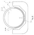
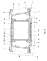
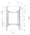
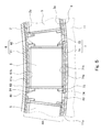
- FIG. 2 is a cross-sectional view taken along line II-II in FIG. It is front sectional drawing which shows the principal part of the 2nd support part by the side of a slide. It is side surface sectional drawing which shows the principal part of the 2nd support part by the side of a slide. It is front sectional drawing which shows the principal part of the 1st support part of a stationary side. It is side surface sectional drawing which shows the principal part of the 1st support part of a stationary side. It is front sectional drawing which shows the inner member and outer member of a modification. It is front sectional drawing which shows the inner member and outer member of another modification.
- FIG. 1 and 2 show a liquefied gas carrier 1 equipped with a double-shell tank 8 having a marine double-shell tank structure according to an embodiment of the present invention.
- two horizontally-placed cylindrical double-shell tanks 8 are mounted on the liquefied gas carrier 1 side by side in the ship length direction.
- Each double shell tank 8 includes an inner tank 2 that stores the liquefied gas 9 and an outer tank 3 that encloses the inner tank 2.
- the liquefied gas 9 is, for example, liquefied petroleum gas (LPG, about ⁇ 45 ° C.), liquefied ethylene gas (LEG, about ⁇ 100 ° C.), liquefied natural gas (LNG, about ⁇ 160 ° C.), liquefied hydrogen (LH 2 , about ⁇ 250 ° C.).
- the inner tank 2 is composed of a trunk portion extending in the lateral direction (captain direction) with a constant cross-sectional shape, and a hemispherical closure portion blocking the openings on both sides of the trunk portion.
- occlusion part may be a flat parallel to a perpendicular direction, and a dish shape may be sufficient as it.
- the outer tub 3 has a shape that secures a space with a certain thickness around the inner tub 2. A space between the outer tub 3 and the inner tub 2 is a vacuum space.
- the hull 12 of the liquefied gas carrier 1 is provided with a pair of saddles 11 corresponding to each tank 8 and spaced apart from each other in the axial direction of the tank 8.
- the pair of saddles 11 support the tank 8 in the vicinity of both ends of the body portion of the inner tank 2.
- Each saddle 11 has a support surface 11 a in surface contact with the outer peripheral surface of the outer tub 3.
- the support surface 11a spreads by approximately 90 degrees from right below the outer tub 3 to both sides when viewed from the axial direction of the tank 8.
- the support surface 11a forms a semicircular recess into which almost half of the outer tub 3 is fitted.
- a pair of support portions 4 ⁇ / b> A and 4 ⁇ / b> B that are separated from each other in the axial direction of the tank 8 are disposed.
- the arrangement positions of the pair of support portions 4A and 4B coincide with the arrangement positions of the pair of saddles 11.
- Each support portion (4 ⁇ / b> A or 4 ⁇ / b> B) supports the inner tub 2 on the inner peripheral surface of the outer tub 3.
- the support part 4A located on the stern side is the first support part on the fixed side
- the support part 4B located on the bow side is the second support part on the slide side.
- the first support portion 4A on the fixed side may be disposed on the bow side
- the second support portion 4B on the slide side may be disposed on the stern side.
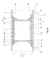
- Each of the first support portion 4A and the second support portion 4B includes a plurality of cylindrical bodies 5 arranged in the circumferential direction of the tank 8, a cylindrical body 5 and an inner tank 2 as shown in FIGS. And a plurality of outer members 7 interposed between the cylindrical body 5 and the outer tub 3.
- Each of the first support portion 4 ⁇ / b> A and the second support portion 4 ⁇ / b> B includes a belt-shaped reinforcing plate 41 that is joined to the outer peripheral surface 2 a of the inner tank 2 and extends in the circumferential direction of the tank 8. Further, as a unique configuration of each support portion, as shown in FIGS.
- the first support portion 4 ⁇ / b> A is fixed on the inner peripheral surface 3 a of the outer tub 3 so as to sandwich all the outer members 7. While including a pair of arc-shaped bars 43, as shown in FIGS. 3 and 4, the second support portion 4B is an arc shape sandwiched between the inner peripheral surface 3a of the outer tub 3 and all the outer members 7. Of the lubricating liner 42.
- Each cylindrical body 5 is arranged so that the axial direction of the cylindrical body 5 coincides with the radial direction of the tank 8. Note that all the cylindrical bodies 5 do not necessarily have to be arranged on the same straight line extending in the circumferential direction of the tank 8, and may be arranged in a staggered manner.
- the cross-sectional shape of each cylindrical body 5 is circular, but the cross-sectional shape of each cylindrical body 5 may be polygonal.
- Each cylindrical body 5 is made of glass fiber reinforced plastic (GFRP).
- GFRP glass fiber reinforced plastic
- the cylindrical body 5 is plated on the inner peripheral surface and the outer peripheral surface of each cylindrical body 5 to form a metal plating layer (not shown). ) Is preferably formed. This plating layer is for preventing outgas from coming out from the cylindrical body 5 made of GFRP facing the vacuum space.
- the outer peripheral surface 2a of the inner tub 2 may be covered with a heat insulating material (not shown) directly or via the reinforcing plate 41 and the inner member 6 both inside and outside the cylindrical body 5. Good. Moreover, the outer peripheral surface and inner peripheral surface of the cylindrical body 5 may be covered with a heat insulating material.
- Each inner member 6 holds the end of each tubular body 5 on the inner tub 2 side on the outer peripheral surface 2a of the inner tub 2.
- the inner member 6 is fixed to the outer peripheral surface 2a of the inner tank 2 via a reinforcing plate 41 by welding or the like.
- a member protruding from the reinforcing plate 41 may be provided around the inner member 6 and the inner member 6 may be fixed to the member by fastening or the like.
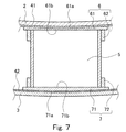
- each inner member 6 is fitted to an inner surface plate 61 that covers the opening on the inner tub 2 side of the cylindrical body 5 and an end portion on the inner tub 2 side of the cylindrical body 5 that protrudes from the inner surface plate 61.
- An inner fitting portion 62 is separate from the inner surface plate 61 and is fixed to the inner surface plate 61 by welding or the like.
- the inner fitting portion 62 may be formed integrally with the inner surface plate 61.
- the inner surface plate 61 does not necessarily need to cover the entire opening of the cylindrical body 5 on the inner tub 2 side, and a large hole may be formed at the center.
- the inner surface plate 61 may be omitted, and the inner member 6 may include only the inner fitting portion 62. From the viewpoint of workability, the cylindrical body 5 and the inner fitting portion 62 may be connected with a pin or the like.
- the inner surface plate 61 is developed along the outer peripheral surface 2a of the inner tub 2 with the same thickness, and the first main surface 61a on the inner tub 2 side and the second main surface 61b on the cylindrical body 5 side are both The outer peripheral surface 2a of the inner tank 2 and the center of curvature are the same curved surface.
- the inner fitting portion 62 has an annular shape in which the end of the cylindrical body 5 on the inner tub 2 side enters the inside. Specifically, the inner fitting portion 62 has an L-shaped cross section, and protrudes radially inward from the peripheral wall 64 overlapping the outer peripheral surface of the cylindrical body 5 and the end of the peripheral wall 64 on the inner tank 2 side. It has a ring part 63 that comes into contact with the end face of the cylindrical body 5.
- the inner diameter of the peripheral wall 64 at room temperature is substantially equal to the outer diameter of the cylindrical body 5.
- the inner tank 2 is thermally contracted.
- the inner member 6 fixed to the inner tank 2 also has a low temperature, it thermally contracts. If the inner fitting portion 62 is fitted to the cylindrical body 5 from the outside, a gap is not formed between the inner fitting portion 62 and the cylindrical body 5 when the inner member 6 is thermally contracted. be able to.
- the ring portion 63 is for filling a space between the second main surface 61 b which is a curved surface of the inner surface plate 61 and the flat end surface of the cylindrical body 5. That is, the thickness of the ring portion 63 gradually increases as the distance from the axial center of the cylindrical body 5 increases in the circumferential direction of the tank 8.
- the inner fitting portion 62 may have only the peripheral wall 64. In this case, the end surface of the cylindrical body 5 may be processed into a curved surface.
- the inner fitting portion 62 preferably has a ring portion 63.
- the inner member 6 is not necessarily separated in the circumferential direction of the tank 8, and all the inner members 6 may be connected.
- the inner plate 61 of all inner members 6 may constitute a single plate.
- the reinforcing plate 41 can be omitted.
- Each outer member 7 holds the end of each tubular body 5 on the outer tub 3 side on the inner peripheral surface 3 a of the outer tub 3.
- a groove extending in the circumferential direction of the tank 8 is formed on the inner peripheral surface 3a of the outer tub 3 by the pair of bars 43 described above, as shown in FIG.
- the outer member 7 of the first support portion 4 ⁇ / b> A is fitted in the groove and is in direct contact with the inner peripheral surface 3 a of the outer tub 3.
- the displacement of the axial direction of the tank 8 with respect to the internal peripheral surface 3a of the outer tank 3 is restrained.
- a block that restrains the displacement of the outer member 7 in the axial direction of the tank 8 may be arranged for each outer member 7.
- the outer member 7 is in contact with the inner peripheral surface 3a of the outer tub 3 through the above-described lubricating liner 42 as shown in FIG.
- the lubrication liner 42 is made of a material having good slidability (for example, fluororesin, molybdenum disulfide).
- the width of the lubricating liner 42 is larger than the width of the outer member 7, and the lubricating liner 42 protrudes on both sides of the outer member 7.
- the outer member 7 of the second support portion 4 ⁇ / b> B can slide on the inner peripheral surface 3 a of the outer tub 3 in the axial direction of the tank 8.
- a gap is formed between the adjacent outer members 7 in both the first support portion 4A and the second support portion 4B. Due to this gap, each outer member 7 can move in the circumferential direction of the tank 8 when the inner tub 2 is contracted by heat shrinkage.
- the lubricating liner 42 is not sandwiched between the outer member 7 and the inner peripheral surface 3a of the outer tub 3 as in the second support portion 4B, but is the same as the second support portion 4B.
- a lubricating liner 42 may be sandwiched between the outer member 7 and the inner peripheral surface 3 a of the outer tub 3.
- each outer member 7 is fitted to the outer surface plate 71 covering the opening of the cylindrical body 5 on the outer tub 3 side, and the end of the cylindrical body 5 on the outer tub 3 side protruding from the outer surface plate 71.
- An outer fitting portion 72 is separate from the outer plate 71 and is fixed to the outer plate 71 by welding or the like.
- the outer fitting portion 72 may be formed integrally with the outer surface plate 71.
- the outer surface plate 71 does not necessarily need to cover the entire opening of the cylindrical body 5 on the outer tub 3 side, and a large hole may be formed at the center.
- the outer plate 71 may be omitted, and the outer member 7 may include only the outer fitting portion 72.
- the cylindrical body 5 and the outer fitting portion 72 may be connected with a pin or the like.
- the outer surface plate 71 is developed along the inner peripheral surface 3a of the outer tub 3 with the same thickness, and the first main surface 71a on the outer tub 3 side and the second main surface 71b on the cylindrical body 5 side are provided. In both cases, the inner peripheral surface 3a of the outer tub 3 and the center of curvature are the same curved surface.
- the outer fitting portion 72 has an annular shape in which the end of the cylindrical body 5 on the outer tub 3 side enters the inside.
- the outer tub 3 remains at room temperature even when a low-temperature liquefied gas 9 is introduced into the inner tub 2, the temperature of the outer member 7 does not decrease so much, unlike the inner member 6. Therefore, the outer fitting portion 72 may be fitted to the cylindrical body 5 from the outside as in the present embodiment, or may be fitted to the cylindrical body 5 from the inner side as opposed to the present embodiment. Also good.
- the outer fitting portion 72 has an L-shaped cross section and protrudes radially inward from the peripheral wall 74 that overlaps the outer peripheral surface of the cylindrical body 5 and the end of the peripheral wall 74 on the outer tub 3 side. It has a ring part 73 that comes into contact with the end face of the cylindrical body 5.
- the ring portion 73 is for filling a space between the second main surface 71 b which is a curved surface of the outer surface plate 71 and the flat end surface of the cylindrical body 5. That is, the thickness of the ring portion 73 gradually decreases as the distance from the axial center of the cylindrical body 5 increases in the circumferential direction of the tank 8.
- the outer fitting portion 72 may have only the peripheral wall 74. In this case, the end surface of the cylindrical body 5 may be processed into a curved surface.
- the outer fitting portion 72 preferably has a ring portion 73.
- the cylindrical bodies 5 arranged in the circumferential direction of the tank 8 and the inner member 6 and the outer member 7 sandwiching them are expanded in the circumferential direction of the tank 8.
- a hollow load transmission structure is configured.
- the axial direction of each cylindrical body 5 matches the radial direction of the tank 8, the load of the inner tank 2 including the contents is compressed in the axial direction of each cylindrical body 5 regardless of the attitude of the ship. Distributed in power. Accordingly, each of the first support portion 4A and the second support portion 4B can withstand the load of the inner tank 2 even when the ship is shaken.
- GFRP having a low thermal conductivity is used as the material constituting each cylindrical body 5, it is possible to further suppress the heat intrusion via the support portions 4A and 4B.
- the inner member 6 is fixed to the inner tank 2, the outer member 7 of the first support portion 4A is restrained in the axial direction of the tank 8, and the outer member 7 of the second support portion 4B is slidable in the axial direction of the tank 8. Therefore, it is possible to cope with contraction due to thermal contraction of the inner tank 2.
- a gap is formed between the adjacent outer members 7 so that the outer members 7 can move in the circumferential direction of the tank 8.
- the outer member 7 can be moved together with the cylindrical body 5 when the inner tub 2 is contracted by heat shrinkage.
- each outer member 7 since each outer member 7 includes the outer fitting portion 72, the end of the cylindrical body 5 on the outer tub 3 side can be held in a simple shape. Further, since each outer member 7 also includes an outer surface plate 71, the outer surface plate 71 can be brought into contact with the inner peripheral surface 3 a of the outer tub 3 in a large area to reduce the contact pressure. Can be slid.
- each inner member 6 also includes the inner fitting portion 62, the end of the cylindrical body 5 on the inner tub 2 side can be held in a simple shape.
- Inner member The inner fitting part 62 of the inner member 6 does not necessarily need to be fitted to the tubular body 5 from the outside, and may be fitted to the tubular body 5 from the inside.
- the inner fitting portion 62 may have a disk shape that enters the opening on the inner tub 2 side of the cylindrical body 5.
- the joining portion 62 is desirably fitted into the cylindrical body 5 from the outside.
- the inner member 6 does not necessarily need to have the inner fitting portion 62.
- a flange may be integrally provided on the cylindrical body 5, and the flange may be fastened by a nut to a bolt protruding from the inner surface plate 61.
- the second main surface 61b on the cylindrical body 5 side of the inner surface plate 61 does not necessarily have to be a curved surface having the same center of curvature as the outer peripheral surface 2a of the inner tub 2. As shown in FIG. It may be a plane perpendicular to the radial direction. If it is this structure, the inner member 6 can be made into a simpler shape.
- the inner member 6 may be an annular member 65 in which a groove 65 a into which an end of the cylindrical body 5 on the inner tub 2 side is fitted is formed.
- the inner member 6 can be a single component, for example, and the number of components can be reduced.
- outer member 7 is not necessarily separated in the circumferential direction of the tank 8, and some or all of the outer members 7 may be connected. However, at least in the support part 4B on the slide side, it is desirable that a gap is formed between the adjacent outer members 7 so that each outer member 7 can move not only in the axial direction of the tank 8 but also in the circumferential direction. With this configuration, the outer member 7 can be slid in the axial direction of the tank 8 (the lubricating liner 42 in the above embodiment) can be rationally used to cope with the reduced diameter of the inner tank 2. .
- the outer member 7 does not necessarily need to have the outer fitting portion 72.
- the cylindrical body 5 may be integrally provided with a flange, and the flange may be fastened by a nut to a bolt protruding from the outer surface plate 71. Or you may fasten the cylindrical body 5 and the outer surface board 71 using a L-shaped metal fitting.
- the second main surface 71b of the outer surface plate 71 on the cylindrical body 5 side is not necessarily a curved surface having the same center of curvature as the inner peripheral surface 3a of the outer tub 3, and as shown in FIG. It may be a plane perpendicular to the radial direction. With this configuration, the outer member 7 can have a simpler shape.
- the outer member 7 may be an annular member 75 in which a groove 75a into which an end of the cylindrical body 5 on the outer tub 3 side is fitted is formed.
- the outer member 7 can be a single component, for example, and the number of components can be reduced.
- the lubricating liner 42 does not necessarily have to be sandwiched between the outer member 7 and the inner peripheral surface 3a of the outer tub 3.
- the outer surface plate 71 of the outer member 7 can be made of a resin having good sliding properties.
- lubricating oil may be applied on the inner peripheral surface 3a of the outer tub 3 with which the outer surface plate 71 contacts.
- the outer member 7 and the outer tub can be configured with a simple configuration. 3 and the inner peripheral surface 3a can be reduced. Thereby, it is possible to prevent an excessive shearing force from acting on the cylindrical body 5.
- the marine double-shell tank structure of the present invention is particularly useful for a liquefied gas carrier ship that transports a low-temperature liquefied gas at sea.
Landscapes
- Engineering & Computer Science (AREA)
- Mechanical Engineering (AREA)
- Chemical & Material Sciences (AREA)
- Combustion & Propulsion (AREA)
- Ocean & Marine Engineering (AREA)
- General Engineering & Computer Science (AREA)
- Physics & Mathematics (AREA)
- Thermal Sciences (AREA)
- Transportation (AREA)
- Filling Or Discharging Of Gas Storage Vessels (AREA)
Abstract
Description
(1)内側部材
内側部材6の内側嵌合部62は、必ずしも筒状体5に外側から嵌合する必要はなく、筒状体5に内側から嵌合していてもよい。例えば、内側嵌合部62は、筒状体5の内槽2側の開口内に入り込む円盤状をなしていてもよい。ただし、前記実施形態で説明したように、内側部材6が低温となったときの内側嵌合部62と筒状体5の間に隙間が形成されることを防止するという観点からは、内側嵌合部62は筒状体5に外側から嵌合することが望ましい。
外側部材7は必ずしもタンク8の周方向に分離している必要はなく、外側部材7のうちのいくつかまたは全てがつながっていてもよい。ただし、少なくともスライド側の支持部4Bでは、隣り合う外側部材7の間に隙間が形成されていて各外側部材7がタンク8の軸方向だけでなく周方向にも移動可能であることが望ましい。この構成であれば、外側部材7をタンク8の軸方向にスライド可能とした構成(前記実施形態では潤滑ライナー42)を合理的に利用して内槽2の縮径にも対応することができる。
2 内槽
2a 外周面
3 外槽
3a 内周面
4A 第1支持部
4B 第2支持部
42 潤滑ライナー
5 筒状体
6 内側部材
61 内面板
61a 第1主面
61b 第2主面
62 内側嵌合部
65 環状の部材
65a 溝
7 外側部材
71 外面板
71a 第1主面
71b 第2主面
72 外側嵌合部
75 環状の部材
75a 溝
8 二重殻タンク
Claims (15)
- 船舶に搭載される横置き円筒状の二重殻タンクの構造であって、
液化ガスを貯蔵する内槽と、
前記内槽との間に真空空間を確保する外槽と、
前記内槽と前記外槽の間に配置された、前記タンクの軸方向に互いに離間する位置で前記内槽を支持する一対の支持部と、を備え、
前記一対の支持部のそれぞれは、各々の軸方向が前記タンクの径方向と合致するように前記タンクの周方向に配列された複数の筒状体と、前記内槽の外周面上で前記筒状体の前記内槽側の端部をそれぞれ保持する複数の内側部材と、前記外槽の内周面上で前記筒状体の前記外槽側の端部をそれぞれ保持する複数の外側部材と、を含み、
前記筒状体のそれぞれは、ガラス繊維強化プラスチックからなる、船舶用二重殻タンク構造。 - 前記筒状体のそれぞれの内周面および外周面上には、金属のめっき層が形成されている、請求項1に記載の船舶用二重殻タンク構造。
- 前記内側部材のそれぞれは、前記筒状体の前記内槽側の端部と嵌合する内側嵌合部を含む、請求項1または2に記載の船舶用二重殻タンク構造。
- 前記内側嵌合部は、前記筒状体の前記内槽側の端部が内部に入り込む環状をなしている、請求項3に記載の船舶用二重殻タンク構造。
- 前記内側部材のそれぞれは、前記筒状体の前記内槽側の開口を覆う内面板を含み、前記内側嵌合部は、前記内面板から突出している、請求項3または4に記載の船舶用二重殻タンク構造。
- 前記内面板の前記内槽側の第1主面は、前記内槽の外周面と曲率中心が同一の曲面であり、前記内面板の前記筒状体側の第2主面は、前記タンクの径方向に垂直な平面である、請求項5に記載の船舶用二重殻タンク構造。
- 前記内側部材のそれぞれは、前記筒状体の前記内槽側の端部が嵌まり込む溝が形成された環状の部材である、請求項1または2に記載の船舶用二重殻タンク構造。
- 前記外側部材のそれぞれは、前記筒状体の前記外槽側の端部と嵌合する外側嵌合部を含む、請求項1~7のいずれか一項に記載の船舶用二重殻タンク構造。
- 前記外側部材のそれぞれは、前記筒状体の前記外槽側の開口を覆う外面板を含み、前記外側嵌合部は、前記外面板から突出している、請求項8に記載の船舶用二重殻タンク構造。
- 前記外面板の前記外槽側の第1主面は、前記外槽の内周面と曲率中心が同一の曲面であり、前記内面板の前記筒状体側の第2主面は、前記タンクの径方向に垂直な平面である、請求項9に記載の船舶用二重殻タンク構造。
- 前記外側部材のそれぞれは、前記筒状体の前記外槽側の端部が嵌まり込む溝が形成された環状の部材である、請求項1~7のいずれか一項に記載の船舶用二重殻タンク構造。
- 前記内側部材は、前記内槽に固定されており、
前記一対の支持部の一方の前記外側部材は、前記外槽に対する前記タンクの軸方向の変位が拘束されるように構成されており、
前記一対の支持部の他方の前記外側部材は、前記外槽の内周面上を前記タンクの軸方向にスライドできるように構成されている、請求項1~11のいずれか一項に記載の船舶用二重殻タンク構造。 - 前記一対の支持部のそれぞれにおける隣り合う前記外側部材の間には、前記タンクの周方向における各外側部材の移動を可能とする隙間が形成されている、請求項12に記載の船舶用二重殻タンク構造。
- 前記一対の支持部の他方の前記外側部材と前記外槽の内周面との間には、潤滑ライナーが挟まれている、請求項12または13に記載の船舶用二重殻タンク構造。
- 請求項1~14のいずれか一項に記載の船舶用二重殻タンク構造を有する、横置き円筒状の二重殻タンクと、
前記一対の支持部と対応する位置で前記タンクを支持する一対のサドルと、
を備えた液化ガス運搬船。
Priority Applications (6)
| Application Number | Priority Date | Filing Date | Title |
|---|---|---|---|
| JP2015513559A JP6027678B2 (ja) | 2013-04-23 | 2014-04-21 | 船舶用二重殻タンク構造および液化ガス運搬船 |
| BR112015025930A BR112015025930A8 (pt) | 2013-04-23 | 2014-04-21 | estrutura de tanque de carcaça dupla para uso em navios e carreador de gás liquefeito |
| EP14787872.2A EP2990715B1 (en) | 2013-04-23 | 2014-04-21 | Double-shell ship tank structure and liquefied gas carrier |
| KR1020157032759A KR101802397B1 (ko) | 2013-04-23 | 2014-04-21 | 선박용 2중각 탱크 구조 및 액화 가스 운반선 |
| CN201480021749.2A CN105102875B (zh) | 2013-04-23 | 2014-04-21 | 船舶用双壳储罐结构以及液化气体搬运船 |
| US14/786,731 US9656729B2 (en) | 2013-04-23 | 2014-04-21 | Double-shell ship tank structure and liquefied gas carrier |
Applications Claiming Priority (2)
| Application Number | Priority Date | Filing Date | Title |
|---|---|---|---|
| JP2013-090098 | 2013-04-23 | ||
| JP2013090098 | 2013-04-23 |
Publications (1)
| Publication Number | Publication Date |
|---|---|
| WO2014174820A1 true WO2014174820A1 (ja) | 2014-10-30 |
Family
ID=51791408
Family Applications (1)
| Application Number | Title | Priority Date | Filing Date |
|---|---|---|---|
| PCT/JP2014/002222 Ceased WO2014174820A1 (ja) | 2013-04-23 | 2014-04-21 | 船舶用二重殻タンク構造および液化ガス運搬船 |
Country Status (7)
| Country | Link |
|---|---|
| US (1) | US9656729B2 (ja) |
| EP (1) | EP2990715B1 (ja) |
| JP (1) | JP6027678B2 (ja) |
| KR (1) | KR101802397B1 (ja) |
| CN (1) | CN105102875B (ja) |
| BR (1) | BR112015025930A8 (ja) |
| WO (1) | WO2014174820A1 (ja) |
Cited By (4)
| Publication number | Priority date | Publication date | Assignee | Title |
|---|---|---|---|---|
| WO2017069196A1 (ja) * | 2015-10-20 | 2017-04-27 | 川崎重工業株式会社 | 舶用二重殻タンクおよび船舶 |
| KR101774112B1 (ko) * | 2015-11-20 | 2017-09-04 | 주식회사 엔케이 | 액화 가스 저장 용기 |
| KR20220048083A (ko) * | 2020-10-12 | 2022-04-19 | 삼성중공업 주식회사 | 선박 |
| WO2023032615A1 (ja) | 2021-09-03 | 2023-03-09 | 川崎重工業株式会社 | 液化水素タンク及びその設計方法 |
Families Citing this family (4)
| Publication number | Priority date | Publication date | Assignee | Title |
|---|---|---|---|---|
| KR102351018B1 (ko) * | 2017-03-16 | 2022-01-14 | 대우조선해양 주식회사 | Lng 저장 iso 탱크 컨테이너 |
| WO2019009826A1 (en) * | 2017-07-05 | 2019-01-10 | Worthington Aritaş Basinçli Kaplar Sanayi̇ Anoni̇m Şi̇rketi̇ | ANNULAR SPACE SEPARATION MECHANISM FOR CRYOGENIC RESERVOIRS |
| JP7161293B2 (ja) * | 2018-03-02 | 2022-10-26 | 川崎重工業株式会社 | 二重殻タンクおよび液化ガス運搬船 |
| JP7379211B2 (ja) * | 2020-02-28 | 2023-11-14 | 三菱造船株式会社 | 燃料タンク、及び船舶 |
Citations (5)
| Publication number | Priority date | Publication date | Assignee | Title |
|---|---|---|---|---|
| JPS60245899A (ja) | 1984-05-21 | 1985-12-05 | Hitachi Ltd | 極低温容器の断熱支持装置 |
| JPS6268099U (ja) * | 1985-10-18 | 1987-04-28 | ||
| JPH06159593A (ja) | 1992-11-13 | 1994-06-07 | Mitsubishi Heavy Ind Ltd | 二重貯槽における内槽支持構造 |
| JPH06323498A (ja) * | 1993-05-14 | 1994-11-25 | Ishikawajima Harima Heavy Ind Co Ltd | 液体ガス貯蔵装置およびその運搬船 |
| JP2014074452A (ja) * | 2012-10-04 | 2014-04-24 | Air Water Plant & Engineering Inc | 低温用真空断熱容器 |
Family Cites Families (18)
| Publication number | Priority date | Publication date | Assignee | Title |
|---|---|---|---|---|
| US2706575A (en) * | 1951-03-06 | 1955-04-19 | Air Reduction | Supports for double-walled containers |
| BE757663A (fr) | 1969-10-18 | 1971-04-01 | Kvaerner Brug As | Perfectionnements a des reservoirs montes separement a bord d'un navir |
| USRE29424E (en) | 1970-10-15 | 1977-10-04 | Kvaerner Brug As | Tank construction for liquified and/or compressed gas |
| ES401734A1 (es) | 1972-04-13 | 1972-10-16 | Sener Tecnica Industrial | Perfeccionamientos en soportes para tanques de revolucion de eje vertical a bordo de buques. |
| NO146351C (no) * | 1978-11-24 | 1982-09-15 | East West Marine | Anordning ved opplagring. |
| KR830001295B1 (ko) | 1979-12-27 | 1983-07-06 | 아아르세드 해랄드 | 저온액화 가스운송용 탱크 지지장치 |
| JP3392911B2 (ja) | 1992-12-28 | 2003-03-31 | オリンパス光学工業株式会社 | 電子内視鏡装置 |
| JP3708055B2 (ja) | 2002-02-14 | 2005-10-19 | 株式会社川崎造船 | 液化ガスタンクの支持構造 |
| DE102006018639A1 (de) | 2006-04-21 | 2007-10-31 | Magna Steyr Fahrzeugtechnik Ag & Co. Kg | Von einem Außenbehälter umgebener und zur Aufnahme einer kryogenen Flüssigkeit dienender Innenbehälter |
| JP2008164066A (ja) | 2006-12-28 | 2008-07-17 | Meisei Ind Co Ltd | 低温液化ガス貯留タンクの支持構造 |
| CN201177156Y (zh) | 2007-12-17 | 2009-01-07 | 辽河石油勘探局 | 一种液化天然气槽车储罐内支撑结构 |
| US8245658B2 (en) * | 2008-07-09 | 2012-08-21 | John Randolph Holland | Systems and methods for supporting tanks in a cargo ship |
| WO2010042075A1 (en) | 2008-10-09 | 2010-04-15 | Keppel Offshore & Marine Technology Centre Pte Ltd | Hull conversion of existing vessels for tank integration |
| KR20120105308A (ko) | 2011-03-15 | 2012-09-25 | 에스티엑스조선해양 주식회사 | 선박에 탑재되는 탱크의 구속 방법 |
| KR20130001844A (ko) | 2011-06-28 | 2013-01-07 | 현대중공업 주식회사 | 진공 단열형 저장 탱크의 지지 구조체 |
| JP2013053674A (ja) | 2011-09-05 | 2013-03-21 | Izumi Steel Works Ltd | 液化ガスタンクの支持構造 |
| CN103032673A (zh) | 2012-12-21 | 2013-04-10 | 山东宏达科技集团有限公司 | 卧式深冷容器内外胆支撑结构 |
| DE202013101162U1 (de) | 2013-02-25 | 2013-03-27 | Olaf Berghoff | Tank für kryogene Fluide |
-
2014
- 2014-04-21 EP EP14787872.2A patent/EP2990715B1/en active Active
- 2014-04-21 WO PCT/JP2014/002222 patent/WO2014174820A1/ja not_active Ceased
- 2014-04-21 CN CN201480021749.2A patent/CN105102875B/zh active Active
- 2014-04-21 BR BR112015025930A patent/BR112015025930A8/pt not_active IP Right Cessation
- 2014-04-21 KR KR1020157032759A patent/KR101802397B1/ko active Active
- 2014-04-21 JP JP2015513559A patent/JP6027678B2/ja active Active
- 2014-04-21 US US14/786,731 patent/US9656729B2/en active Active
Patent Citations (5)
| Publication number | Priority date | Publication date | Assignee | Title |
|---|---|---|---|---|
| JPS60245899A (ja) | 1984-05-21 | 1985-12-05 | Hitachi Ltd | 極低温容器の断熱支持装置 |
| JPS6268099U (ja) * | 1985-10-18 | 1987-04-28 | ||
| JPH06159593A (ja) | 1992-11-13 | 1994-06-07 | Mitsubishi Heavy Ind Ltd | 二重貯槽における内槽支持構造 |
| JPH06323498A (ja) * | 1993-05-14 | 1994-11-25 | Ishikawajima Harima Heavy Ind Co Ltd | 液体ガス貯蔵装置およびその運搬船 |
| JP2014074452A (ja) * | 2012-10-04 | 2014-04-24 | Air Water Plant & Engineering Inc | 低温用真空断熱容器 |
Non-Patent Citations (1)
| Title |
|---|
| See also references of EP2990715A4 |
Cited By (8)
| Publication number | Priority date | Publication date | Assignee | Title |
|---|---|---|---|---|
| WO2017069196A1 (ja) * | 2015-10-20 | 2017-04-27 | 川崎重工業株式会社 | 舶用二重殻タンクおよび船舶 |
| CN108137135A (zh) * | 2015-10-20 | 2018-06-08 | 川崎重工业株式会社 | 船用双壳储罐及船舶 |
| CN108137135B (zh) * | 2015-10-20 | 2020-04-07 | 川崎重工业株式会社 | 船用双壳储罐及船舶 |
| KR101774112B1 (ko) * | 2015-11-20 | 2017-09-04 | 주식회사 엔케이 | 액화 가스 저장 용기 |
| KR20220048083A (ko) * | 2020-10-12 | 2022-04-19 | 삼성중공업 주식회사 | 선박 |
| KR102904575B1 (ko) | 2020-10-12 | 2025-12-24 | 삼성중공업 주식회사 | 선박 |
| WO2023032615A1 (ja) | 2021-09-03 | 2023-03-09 | 川崎重工業株式会社 | 液化水素タンク及びその設計方法 |
| KR20240047398A (ko) | 2021-09-03 | 2024-04-12 | 카와사키 주코교 카부시키 카이샤 | 액화 수소 탱크 및 그 설계 방법 |
Also Published As
| Publication number | Publication date |
|---|---|
| EP2990715A4 (en) | 2016-12-21 |
| JP6027678B2 (ja) | 2016-11-16 |
| BR112015025930A8 (pt) | 2020-01-14 |
| BR112015025930A2 (pt) | 2017-07-25 |
| KR20150143797A (ko) | 2015-12-23 |
| JPWO2014174820A1 (ja) | 2017-02-23 |
| CN105102875B (zh) | 2018-01-05 |
| EP2990715A1 (en) | 2016-03-02 |
| US9656729B2 (en) | 2017-05-23 |
| KR101802397B1 (ko) | 2017-11-28 |
| US20160075412A1 (en) | 2016-03-17 |
| CN105102875A (zh) | 2015-11-25 |
| EP2990715B1 (en) | 2021-07-14 |
Similar Documents
| Publication | Publication Date | Title |
|---|---|---|
| JP6027678B2 (ja) | 船舶用二重殻タンク構造および液化ガス運搬船 | |
| JP6031188B2 (ja) | 船舶用タンクの支持構造および液化ガス運搬船 | |
| CN105308382B (zh) | 双重壳储罐以及液化气体搬运船 | |
| KR102013043B1 (ko) | Lng 이중저장탱크용 지지장치 | |
| JP6170636B2 (ja) | 船舶用タンクの支持構造 | |
| KR101747425B1 (ko) | 선박 카고탱크 돔의 복층 실링부재 | |
| EP3760910B1 (en) | Double-shell tank and liquefied gas carrier ship | |
| WO2017154698A1 (ja) | 液化ガスタンクの防熱構造およびそれを用いた液化ガスタンク | |
| KR20120013254A (ko) | 액화천연가스 저장 탱크의 펌프타워 구조체 | |
| KR20120013258A (ko) | 코너부 단열 보드 및 이를 구비한 액화 천연가스 저장 탱크 | |
| WO2021106311A1 (ja) | タンクの支持構造、船舶 | |
| KR102862806B1 (ko) | 액화가스 저장탱크 및 이를 포함하는 선박 | |
| EP4230902A1 (en) | Double-walled heat insulation piping unit for liquefied gas, and liquefied gas storage vessel comprising same | |
| KR20150117930A (ko) | 내조 연결구조체 | |
| KR20150093329A (ko) | 원형 멤브레인 탱크 및 원형 멤브레인 선박 | |
| JP7793807B2 (ja) | 多重殻タンク及び船舶 | |
| WO2022145384A1 (ja) | 極低温液体用配管構造及びそれを備えた船舶 |
Legal Events
| Date | Code | Title | Description |
|---|---|---|---|
| WWE | Wipo information: entry into national phase |
Ref document number: 201480021749.2 Country of ref document: CN |
|
| 121 | Ep: the epo has been informed by wipo that ep was designated in this application |
Ref document number: 14787872 Country of ref document: EP Kind code of ref document: A1 |
|
| ENP | Entry into the national phase |
Ref document number: 2015513559 Country of ref document: JP Kind code of ref document: A |
|
| NENP | Non-entry into the national phase |
Ref country code: DE |
|
| WWE | Wipo information: entry into national phase |
Ref document number: 14786731 Country of ref document: US |
|
| WWE | Wipo information: entry into national phase |
Ref document number: 2014787872 Country of ref document: EP |
|
| ENP | Entry into the national phase |
Ref document number: 20157032759 Country of ref document: KR Kind code of ref document: A |
|
| REG | Reference to national code |
Ref country code: BR Ref legal event code: B01A Ref document number: 112015025930 Country of ref document: BR |
|
| ENP | Entry into the national phase |
Ref document number: 112015025930 Country of ref document: BR Kind code of ref document: A2 Effective date: 20151013 |