WO2021106311A1 - タンクの支持構造、船舶 - Google Patents
タンクの支持構造、船舶 Download PDFInfo
- Publication number
- WO2021106311A1 WO2021106311A1 PCT/JP2020/033922 JP2020033922W WO2021106311A1 WO 2021106311 A1 WO2021106311 A1 WO 2021106311A1 JP 2020033922 W JP2020033922 W JP 2020033922W WO 2021106311 A1 WO2021106311 A1 WO 2021106311A1
- Authority
- WO
- WIPO (PCT)
- Prior art keywords
- tank
- portions
- support
- longitudinal direction
- protruding
- Prior art date
Links
Images


Classifications
-
- B—PERFORMING OPERATIONS; TRANSPORTING
- B63—SHIPS OR OTHER WATERBORNE VESSELS; RELATED EQUIPMENT
- B63B—SHIPS OR OTHER WATERBORNE VESSELS; EQUIPMENT FOR SHIPPING
- B63B25/00—Load-accommodating arrangements, e.g. stowing, trimming; Vessels characterised thereby
- B63B25/02—Load-accommodating arrangements, e.g. stowing, trimming; Vessels characterised thereby for bulk goods
- B63B25/08—Load-accommodating arrangements, e.g. stowing, trimming; Vessels characterised thereby for bulk goods fluid
- B63B25/12—Load-accommodating arrangements, e.g. stowing, trimming; Vessels characterised thereby for bulk goods fluid closed
- B63B25/16—Load-accommodating arrangements, e.g. stowing, trimming; Vessels characterised thereby for bulk goods fluid closed heat-insulated
-
- B—PERFORMING OPERATIONS; TRANSPORTING
- B65—CONVEYING; PACKING; STORING; HANDLING THIN OR FILAMENTARY MATERIAL
- B65D—CONTAINERS FOR STORAGE OR TRANSPORT OF ARTICLES OR MATERIALS, e.g. BAGS, BARRELS, BOTTLES, BOXES, CANS, CARTONS, CRATES, DRUMS, JARS, TANKS, HOPPERS, FORWARDING CONTAINERS; ACCESSORIES, CLOSURES, OR FITTINGS THEREFOR; PACKAGING ELEMENTS; PACKAGES
- B65D90/00—Component parts, details or accessories for large containers
- B65D90/12—Supports
-
- F—MECHANICAL ENGINEERING; LIGHTING; HEATING; WEAPONS; BLASTING
- F17—STORING OR DISTRIBUTING GASES OR LIQUIDS
- F17C—VESSELS FOR CONTAINING OR STORING COMPRESSED, LIQUEFIED OR SOLIDIFIED GASES; FIXED-CAPACITY GAS-HOLDERS; FILLING VESSELS WITH, OR DISCHARGING FROM VESSELS, COMPRESSED, LIQUEFIED, OR SOLIDIFIED GASES
- F17C13/00—Details of vessels or of the filling or discharging of vessels
- F17C13/08—Mounting arrangements for vessels
- F17C13/082—Mounting arrangements for vessels for large sea-borne storage vessels
-
- B—PERFORMING OPERATIONS; TRANSPORTING
- B63—SHIPS OR OTHER WATERBORNE VESSELS; RELATED EQUIPMENT
- B63B—SHIPS OR OTHER WATERBORNE VESSELS; EQUIPMENT FOR SHIPPING
- B63B2231/00—Material used for some parts or elements, or for particular purposes
- B63B2231/02—Metallic materials
-
- F—MECHANICAL ENGINEERING; LIGHTING; HEATING; WEAPONS; BLASTING
- F17—STORING OR DISTRIBUTING GASES OR LIQUIDS
- F17C—VESSELS FOR CONTAINING OR STORING COMPRESSED, LIQUEFIED OR SOLIDIFIED GASES; FIXED-CAPACITY GAS-HOLDERS; FILLING VESSELS WITH, OR DISCHARGING FROM VESSELS, COMPRESSED, LIQUEFIED, OR SOLIDIFIED GASES
- F17C2205/00—Vessel construction, in particular mounting arrangements, attachments or identifications means
- F17C2205/01—Mounting arrangements
- F17C2205/0153—Details of mounting arrangements
- F17C2205/018—Supporting feet
-
- F—MECHANICAL ENGINEERING; LIGHTING; HEATING; WEAPONS; BLASTING
- F17—STORING OR DISTRIBUTING GASES OR LIQUIDS
- F17C—VESSELS FOR CONTAINING OR STORING COMPRESSED, LIQUEFIED OR SOLIDIFIED GASES; FIXED-CAPACITY GAS-HOLDERS; FILLING VESSELS WITH, OR DISCHARGING FROM VESSELS, COMPRESSED, LIQUEFIED, OR SOLIDIFIED GASES
- F17C2221/00—Handled fluid, in particular type of fluid
- F17C2221/03—Mixtures
- F17C2221/032—Hydrocarbons
-
- F—MECHANICAL ENGINEERING; LIGHTING; HEATING; WEAPONS; BLASTING
- F17—STORING OR DISTRIBUTING GASES OR LIQUIDS
- F17C—VESSELS FOR CONTAINING OR STORING COMPRESSED, LIQUEFIED OR SOLIDIFIED GASES; FIXED-CAPACITY GAS-HOLDERS; FILLING VESSELS WITH, OR DISCHARGING FROM VESSELS, COMPRESSED, LIQUEFIED, OR SOLIDIFIED GASES
- F17C2270/00—Applications
- F17C2270/01—Applications for fluid transport or storage
- F17C2270/0102—Applications for fluid transport or storage on or in the water
- F17C2270/0105—Ships
Definitions
- the present disclosure relates to a tank support structure and a ship.
- the present application claims priority with respect to Japanese Patent Application No. 2019-216665 filed in Japan on November 29, 2019, the contents of which are incorporated herein by reference.
- Patent Document 1 discloses a configuration in which two support portions (supports) for supporting the tank are provided at intervals in the central axis direction of the tank. In this configuration, one support portion non-displaceably supports the tank with respect to the hull in the central axial direction. The other support portion slidably supports the tank with respect to the hull in the central axis direction.
- the cross-sectional shape orthogonal to the central axis of the tank disclosed in Patent Document 1 is a circular shape.
- Each support portion has a support surface that is recessed in a semicircular shape in order to support the tank from below. Therefore, it is necessary to accurately form the support surface of the support portion according to the curved surface of the lower surface of the tank, and there is a problem that it takes time and effort to manufacture the support portion.
- the present disclosure has been made to solve the above problems, and an object of the present disclosure is to provide a tank support structure and a ship capable of efficiently installing a tank.
- the tank support structure includes a tank, a supported portion, a support portion, and a restraint portion.
- the tank has a tubular shape extending in the horizontal direction as a longitudinal direction.
- a plurality of the supported portions are provided apart from each other in the longitudinal direction.
- the supported portion has a protruding portion.
- the protruding portion protrudes from the tank in a direction orthogonal to the longitudinal direction.
- the support portion has a mounting surface on which the lower surface of the protruding portion is mounted so as to be relatively movable.
- the restraining portion is provided on at least one of the plurality of supporting portions. The restraining portion restrains the protruding portion in the longitudinal direction with respect to the above-mentioned mounting surface.
- the ship according to the present disclosure has a hull and a tank support structure as described above.
- the hull has a pair of broadsides.
- the support portion is provided on the hull.
- the tank can be installed efficiently.
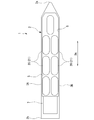
- FIG. 1 It is a top view which shows the schematic structure of the ship which concerns on embodiment of this disclosure. It is a side view of the tank equipment which concerns on embodiment of this disclosure. It is a figure which looked at the tank equipment which concerns on embodiment of this disclosure from the longitudinal direction of a tank equipment. It is a figure which shows the main part of the tank equipment which concerns on embodiment of this disclosure, and is the cross-sectional view taken along the arrow AA of FIG. It is a figure which shows the structure of the support part provided with the restraint part in the tank equipment which concerns on embodiment of this disclosure, and is the cross-sectional view taken along the line BB of FIG. It is a figure which looked at the tank equipment which concerns on the modification of embodiment of this disclosure from the longitudinal direction of a tank equipment. It is a side sectional view of the tank equipment which concerns on the modification of embodiment of this disclosure. It is a side view of the tank equipment which concerns on the modification of embodiment of this disclosure.
- the ship 1 of the embodiment of the present disclosure shown in FIG. 1 carries, for example, liquefied gas such as LNG (Liquefied Natural Gas), LPG (Liquefied Petroleum Gas), liquid carbon dioxide, and liquid ammonia.
- the ship 1 includes at least a hull 2 and a tank facility 20.
- the hull 2 has a pair of side sides 3A and 3B forming its outer shell, a ship bottom (not shown), and an exposed deck 5.
- the side 3A and 3B are provided with a pair of side outer plates forming the left and right side respectively.
- the bottom of the ship (not shown) includes a bottom outer plate connecting these side 3A and 3B. Due to these pair of sideways 3A and 3B and the bottom of the ship (not shown), the outer shell of the hull 2 has a U-shape in a cross section orthogonal to the stern and tail direction Da.
- the exposed deck 5 is an all-deck exposed to the outside.
- an upper structure 7 having a living area is formed on the exposed deck 5 on the stern 2b side.
- a cargo loading section (hold) 8 is formed on the bow 2a side of the superstructure 7.
- the cargo loading compartment 8 is recessed toward the bottom of the ship (not shown) below the exposed deck 5 and opens upward.
- a plurality of tank facilities 20 are arranged in the cargo loading section 8. In this embodiment, for example, a total of seven tank facilities 20 are arranged in the cargo loading section 8.
- the layout and the number of tank facilities 20 installed in the cargo loading section 8 are not limited in any way.
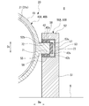
- each tank facility 20 includes a tank 21, supported portions 40A and 40B, support portions 50A and 50B, and a restraint portion 60 (see FIG. 2).
- the tank 21 accommodates liquefied gas.
- the tank 21 is made of a metal material such as an aluminum alloy.
- the tank 21 has a tubular shape extending in the horizontal direction as the longitudinal direction De.
- the tank 21 is arranged so that its longitudinal direction De is aligned with, for example, the hull 2's stern direction Da.
- the direction of the longitudinal direction De of the tank 21 is not limited to the stern and stern direction Da, and may be arranged so as to coincide with the ship width direction.
- the tank 21 includes a body portion 21a and two end plate portions 21b.
- the body portion 21a has a cylindrical shape having a constant diameter along the longitudinal direction De.
- the end plate portions 21b are provided on both sides of the body portion 21a in the longitudinal direction De.
- the end plate portion 21b is arranged so as to close both ends of the body portion 21a in the longitudinal direction De.
- the outer diameter of the end plate portion 21b gradually decreases as it is separated from the body portion 21a along the longitudinal direction De.
- the outer surface of the end plate portion 21b is formed, for example, in a hemispherical shape that is convex toward the outside in the longitudinal direction.
- the end plate portion 21b is not limited to a hemisphere, and may have a curved surface shape formed by combining a plurality of radii of curvature.
- Such a tank 21 is supported by support portions 50A and 50B at two locations spaced apart from each other in the longitudinal direction De.
- the supported portions 40A and 40B are arranged so as to be separated from each other in the longitudinal direction De.
- the supported portion 40A is provided at one end of the body portion 21a of the tank 21 in the longitudinal direction De.
- the supported portion 40B is provided at the other end of the body portion 21a of the tank 21 in the longitudinal direction De.
- the supported portions 40A and 40B each include a ring portion 41 and a protruding portion 42, respectively.
- the supported portions 40A and 40B are preferably formed of the same metal material as the tank 21. This is because when the tank 21 expands and contracts due to the temperature difference between the low-temperature liquefied gas inside the tank 21 and the atmosphere outside the tank 21, the deformations that occur between the tank 21 and the supported portions 40A and 40B are made as similar as possible. ..
- the ring portion 41 is formed in an annular shape extending in the circumferential direction along the outer peripheral surface of the tank 21.
- the protruding portion 42 projects in a direction orthogonal to the longitudinal direction De with respect to the tank 21.
- the projecting portions 42 project from the tank 21 on both sides of the width direction Dw orthogonal to the longitudinal direction De, and a pair is provided in the width direction Dw.
- the pair of protruding portions 42 are integrally formed with the ring portion 41.
- the pair of projecting portions 42 are formed so as to project from the ring portion 41 on both sides of the Dw in the width direction.
- the width direction Dw means the radial direction along the horizontal plane among the radial directions of the tank 21 orthogonal to the longitudinal direction De.
- Such a pair of protruding portions 42 are provided in the intermediate portion of the tank 21 in the vertical direction Dv.
- the pair of protrusions 42 are provided at a position including the central axis O of the tank 21 in the vertical direction Dv (in other words, a position overlapping the central axis O in the vertical direction Dv).
- each protruding portion 42 has a constant thickness in the vertical direction Dv.
- the upper surface 42a and the lower surface 42b of each protrusion 42 are flat surfaces along a horizontal plane orthogonal to the vertical Dv, respectively.
- the support portions 50A and 50B are provided on the deck 9 provided in the cargo loading section 8 of the hull 2.
- a plurality of support portions 50A and 50B are provided apart from each other in the longitudinal direction De.
- the support portion 50A is provided at a position corresponding to the supported portion 40A in the longitudinal direction De.
- the support portion 50B is provided at a position corresponding to the supported portion 40B in the longitudinal direction De.
- the support portions 50A and 50B integrally include a lower support portion 51, an upper support portion 52, and a connecting portion 53, respectively.
- the lower support portion 51 is fixed to the deck 9, for example. In this embodiment, the lower end of the lower support portion 51 is fixed to the deck 9.
- the lower support portion 51 extends upward from the deck 9 in the vertical direction Dv.
- a mounting surface 55 on which the protruding portion 42 is mounted is formed on the upper surface of the lower support portion 51.
- the mounting surface 55 is a flat surface along a horizontal plane orthogonal to the vertical Dv.
- the upper support portion 52 is arranged at an interval above the vertical Dv with respect to the mounting surface 55.
- the lower surface 52b of the upper support portion 52 faces the mounting surface 55 at intervals in the vertical direction Dv.
- the lower surface 52b of the upper support portion 52 illustrated in this embodiment is a flat surface parallel to the mounting surface 55.
- the connecting portion 53 connects the lower support portion 51 and the upper support portion 52.
- the connecting portion 53 is provided on the outside of the tank 21 in the width direction Dw with respect to the mounting surface 55.
- the connecting portion 53 extends upward from the lower supporting portion 51.
- the connecting portion 53 is connected to the outer end portion of the upper supporting portion 52 in the width direction Dw.
- the projecting portion 42 is arranged between the lower support portion 51 and the upper support portion 52 in the vertical direction Dv. In this way, the protruding portion 42 is housed in the supporting portions 50A and 50B.
- a sliding member 56 is provided on the mounting surface 55. Further, a sliding member 57 is provided on the side surface 53s of the connecting portion 53 facing the mounting surface 55 side. A sliding member 58 is provided on the lower surface 52b of the upper support portion 52.
- the sliding members 56, 57, and 58 are flat plates made of stainless steel or the like, and are attached so as to cover the mounting surface 55, the side surface 53s, and the lower surface 52b, respectively. The surfaces of the sliding members 56, 57, 58 are preferably smooth in order to obtain good slidability.
- Insulating materials 71, 72, and 73 are provided on the protruding portions 42 of the supported portions 40A and 40B.
- the heat insulating material 71 is provided along the lower surface 42b of the protrusion 42.
- the heat insulating material 71 is sandwiched between the lower surface 42b of the projecting portion 42 and the sliding member 56 provided on the mounting surface 55.
- the heat insulating material 72 is provided along the upper surface 42a of the protrusion 42.
- the heat insulating material 72 is sandwiched between the upper surface 42a of the protruding portion 42 and the sliding member 58 provided on the lower surface 52b of the upper supporting portion 52.
- the heat insulating material 73 is provided along the side end surface 42s of the protruding portion 42 facing outward in the width direction Dw.
- the heat insulating material 73 is provided between the side end surface 42s of the protruding portion 42 and the sliding member 57 provided on the side surface 53s of the connecting portion 53.
- the heat insulating materials 71, 72, 73 for example, a wood-based material or the like can be used.
- the heat insulating materials 71, 72, and 73 have a plate shape having a predetermined thickness, and are fixed to each of the upper surface 42a, the lower surface 42b, and the side end surface 42s with, for example, an adhesive. In this way, the heat insulating materials 71, 72, 73 are sandwiched between the projecting portions 42 of the supported portions 40A, 40B and the supporting portions 50A, 50B.
- the heat insulating materials 71, 72, and 73 suppress heat transfer from the supported portions 40A and 40B provided in the tank 21 to the supporting portions 50A and 50B.
- the protruding portions 42 of the supported portions 40A and 40B are mounted on the sliding member 56 provided on the mounting surface 55 of the lower support portion 51 via the heat insulating material 71.
- the protrusion 42 is relatively movable on the sliding member 56 in the direction along the horizontal plane, that is, in the longitudinal direction De and the width direction Dw.
- the heat insulating material 73 provided on the side end surface 42s of the protruding portion 42 faces the sliding member 57 provided on the side surface 53s of the connecting portion 53 in the width direction Dw.
- the heat insulating material 72 and the sliding member 57 are arranged at intervals in the width direction Dw.
- the protruding portion 42 is displaced to the outside of the Dw in the width direction due to thermal deformation of the tank 21 and the heat insulating material 73 provided on the protruding portion 42 abuts on the sliding member 57, the protruding portion 42 is still present. It is relatively movable in the longitudinal direction De along the sliding member 57.
- the restraining portion 60 restrains the protruding portion 42 in at least a part of the plurality of supported portions 40A and 40B in the longitudinal direction De with respect to the mounting surface 55.
- the restraint portions 60 are provided on one side of the longitudinal direction De (for example, the bow side) on the support portions 50A provided on both sides of the tank 21 in the width direction Dw.
- the restraint portion 60 may be provided only on the support portion 50A on one side of the width direction Dw of the tank 21 on one side of the longitudinal direction De.
- the restraint portion 60 includes a pair of wall portions 61A and 61B and a fixture 63.
- the pair of wall portions 61A and 61B are provided between the lower support portion 51 and the upper support portion 52 of the support portion 50A.
- the wall portions 61A and 61B are provided on both ends of the mounting surface 55 in the longitudinal direction De.
- the wall portions 61A and 61B are provided along the vertical plane orthogonal to the longitudinal direction De.
- the protruding portion 42 is inserted and arranged between the pair of wall portions 61A and 61B. In the protruding portion 42, heat insulating materials 74 and 75 are adhesively fixed on both sides of the De in the longitudinal direction.
- the fixture 63 is provided on one of the pair of wall portions 61A and 61B, 61A.
- the fixture 63 of this embodiment is screwed into a screw hole 61h formed in the wall portion 61A.
- the fixture 63 is arranged with its central axis along the longitudinal direction De.
- the fixture 63 is rotated around the central axis while being screwed into the screw hole 61h, the fixture 63 is provided so as to be able to advance and retreat toward the other wall portion 61B along the longitudinal direction De.
- the tip of the fixture 63 abuts against the heat insulating material 74 provided on the protrusion 42.
- sliding members 64 and 65 are sandwiched between the heat insulating material 74 and the tip of the fixture 63, and between the heat insulating material 75 and the other wall portion 61B, respectively.
- Such a restraining portion 60 restrains the protruding portion 42 with respect to the mounting surface 55 in the longitudinal direction De. Further, the restraining portion 60 allows the relative displacement of the protruding portion 42 in the width direction Dw by sandwiching the sliding members 64 and 65.
- the supported portions 40A and 40B having the protruding portions 42 protruding from the tank 21 in the direction orthogonal to the longitudinal direction De and the lower surface 42b of the protruding portion 42 are placed so as to be relatively movable.
- the support portions 50A and 50B having the mounting surface 55 to be mounted, and the restraining portion 60 for restraining the protruding portion 42 with respect to the mounting surface 55 in the longitudinal direction De are provided.
- the hull 2 can support the tank 21 of the tank equipment 20 by mounting the protruding portion 42 protruding from the tank 21 on the mounting surface 55 of the support portions 50A and 50B. ..
- the support portions 50A and 50B do not support the tank 21 by the semicircular lower side surface 21r (see FIG. 3), it is necessary to accurately form the mounting surface 55 according to the curved surface of the lower side surface 21r of the tank 21.
- the mounting surface 55 can be easily formed. Further, when installing the tank 21, it is only necessary to mount the protruding portion 42 on the mounting surface 55 of the support portions 50A and 50B, so that the burden on the installation work of the tank 21 can be reduced. As a result, according to the support structure of the tank 21, it is possible to efficiently install the tank 21 while suppressing an increase in the weight of the equipment.
- the lower surface 42b of the protrusion 42 and the mounting surface 55 each form a flat surface along a horizontal plane.
- the protrusion 42 and the mounting surface 55 are formed as compared with the case where the mounting surface 55 is formed so as to match the curved surface of the lower side surface 21r (see FIG. 3) of the tank 21. It can be easily formed. Further, the lower surface 42b of the protrusion 42 can be relatively moved along the horizontal plane on the mounting surface 55. As a result, in the support portion 50B in which the restraint portion 60 is not provided, the tank 21 can be supported so as to be relatively movable in the longitudinal direction De and the width direction Dw.
- the tank 21 can be deformed in the longitudinal direction De and the width direction Dw. Further, even in the support portion 50A provided with the restraint portion 60, the tank 21 can move relative to the support portion 50A in the width direction Dw. Therefore, in the support portion 50A provided with the restraint portion 60, it is possible to allow the tank 21 to be deformed in the width direction Dw.
- the projecting portions 42 are provided as a pair of projecting portions on both sides of the width direction Dw orthogonal to the longitudinal direction De from the tank 21.
- the support portions 50A and 50B accommodate the projecting portions 42 so as to sandwich them from above and below.
- the tank 21 can be mounted on the hull 2 by mounting the pair of protruding portions 42 protruding from the tank 21 on both sides of the Dw in the width direction on the mounting surfaces 55 of the support portions 50A and 50B. It can be supported more stably.
- the support portions 50A and 50B accommodate the projecting portions 42 so as to sandwich them from above and below.
- the protruding portion 42 is constrained in the vertical direction Dv by the supporting portions 50A and 50B. Therefore, it is not necessary to provide a mechanism for preventing the tank 21 from floating apart from the support portions 50A and 50B. As a result, according to the support structure of the tank 21, the tank 21 can be installed efficiently.
- the supported portions 40A and 40B further include an annular ring portion 41 extending in the circumferential direction along the outer peripheral surface of the tank 21, and the pair of protruding portions 42 is the ring portion 41. It is provided so as to project from both sides of the Dw in the width direction. According to such a support structure of the tank 21, the tank 21 can be supported more stably by providing the support portions 50A and 50B with the annular ring portion 41. Further, by providing the protruding portion 42 so as to protrude from the ring portion 41 on both sides of the Dw in the width direction, it is possible to suppress stress concentration on the base portion of the protruding portion 42.
- a pair of protruding portions 42 are provided in the vertical Dv intermediate portion of the tank 21. Therefore, as compared with the case where the tank 21 is supported by the lower side surface 21r, it is possible to suppress the displacement amount when the tank 21 is deformed in the vertical direction Dv at the upper end portion 21t and the lower end portion 21s (see FIG. 3) of the tank 21. it can. Therefore, when a pipe or the like is connected to the upper end portion 21t or the lower end portion 21s of the tank 21, it is possible to suppress the stress or the like exerted on the pipe or the like due to the deformation of the tank 21.
- the support portions 50A and 50B are the lower support portion 51 having the mounting surface 55 and the upper support portions arranged at intervals in the vertical direction Dv with respect to the mounting surface 55.
- a portion 52 and a connecting portion 53 for connecting the lower support portion 51 and the upper support portion 52 are provided.
- the projecting portion 42 is accommodated so as to be sandwiched between the mounting surface 55 of the lower support portion 51 and the upper support portion 52 from above and below, and is accommodated in the support portions 50A and 50B.
- the support portions 50A and 50B having both the function of supporting the tank 21 and the function of suppressing the lifting of the tank 21 can be realized with a simple structure.
- the restraint portion 60 is provided on one of the pair of wall portions 61A and 61B and the pair of wall portions 61A and 61B provided on both sides in the longitudinal direction De with respect to the protruding portion 42.
- the fixture 63 provided is provided. According to such a support structure of the tank 21, when assembling the tank equipment 20, after inserting the protrusion 42 between the pair of wall portions 61A and 61B, the fixture 63 is placed in the longitudinal direction with respect to the protrusion 42. If it is advanced to De, the protruding portion 42 can be sandwiched between the fixture 63 and the wall portion 61B. As a result, the protrusion 42 is constrained in the longitudinal direction De.
- the restraint portion 60 By configuring the restraint portion 60 using the fixture 63 in this way, the protrusion 42 can be easily inserted between the pair of wall portions 61A and 61B in a state where the fixture 63 is loosened. .. Therefore, the tank equipment 20 can be easily assembled.
- the tank 21 and the supported portions 40A and 40B are formed of a metal material and are sandwiched between the protruding portions 42 of the supported portions 40A and 40B and the supporting portions 50A and 50B. It is further provided with heat insulating materials 71 to 75. According to such a support structure of the tank 21, by forming the tank 21 and the supported portions 40A and 40B from a metal material, the amount of thermal deformation of the tank 21 and the heat of the tank 21 are propagated to be supported. The difference between the portions 40A and 40B and the amount of thermal deformation can be suppressed.
- the ship 1 of the above embodiment includes a hull 2 having a pair of side sides 3A and 3B and a support structure of a tank 21 provided in the hull 2, and the support portions 50A and 50B are provided on the hull 2. .. According to such a ship 1, it is possible to provide a ship 1 capable of efficiently installing the tank 21 while suppressing an increase in the equipment weight.
- a pair of projecting portions 42 projecting from the tank 21 on both sides of the width direction Dw orthogonal to the longitudinal direction De are provided, but the present invention is not limited to this.
- the tank 21 may be supported by the supported portions 40C and 40D having the protruding portions 42B protruding downward from the tank 21.
- the supported portions 40C and 40D are arranged so as to be separated from each other in the longitudinal direction De.
- the supported portions 40C and 40D each include a ring portion 41 and a protruding portion 42B, respectively.
- the protruding portion 42B projects downward from the vertical direction Dv with respect to the tank 21 at right angles to the longitudinal direction De.
- the protrusion 42B is provided at the bottom of the tank 21.
- the lower surface 42d of the protrusion 42B is a flat surface along a horizontal plane orthogonal to the vertical Dv.
- the support portions 50C and 50D have a mounting surface 55B on which the lower surface 42d of the protruding portion 42 is mounted so as to be relatively movable.
- the support portions 50C and 50D each include a lower support portion 101 and a side support portion 102, respectively.
- the lower support portion 101 is fixed to the deck 9, for example.
- a mounting surface 55B on which the protruding portion 42B is mounted is formed on the upper surface of the lower support portion 101.
- the mounting surface 55B is a flat surface along a horizontal plane orthogonal to the vertical Dv.
- the side support portions 102 are arranged at intervals on both sides in the width direction Dw with respect to the mounting surface 55B.
- the projecting portion 42B is arranged above the mounting surface 55B of the lower support portion 101 and between the side support portions 102 on both sides in the width direction Dw.
- a sliding member 111 is provided on the mounting surface 55B. Further, sliding members 112 are provided on the protruding portions 42B side of the side portion supporting portions 102, respectively.
- Each of the sliding members 111 and 112 has a flat plate shape made of stainless steel or the like. The surfaces of the sliding members 111 and 112 are preferably smooth in order to obtain good slidability.
- the protruding portions 42B of the supported portions 40C and 40D are provided with heat insulating materials 121 and 122 at positions facing the sliding members 111 and 112.
- heat insulating materials 121 and 122 for example, a wood-based material or the like can be used.
- the heat insulating materials 121 and 122 have a plate shape having a predetermined thickness, and are fixed to the protruding portion 42B with, for example, an adhesive or the like. In this way, the heat insulating materials 121 and 122 are sandwiched between the projecting portions 42B of the supported portions 40C and 40D and the supporting portions 50C and 50D.
- the heat insulating materials 121 and 122 suppress heat transfer from the supported portions 40C and 40D provided in the tank 21 to the supporting portions 50C and 50D.
- the protruding portion 42B can move relative to the longitudinal direction De along the sliding members 111 and 112.
- the protrusion 42B is restrained from being displaced in the width direction by a fixing member 131 such as a bolt provided on the pair of side support portions 102.
- a restraint portion 60B is provided on the support portion 50C provided on one side of the longitudinal direction De.
- the restraining portion 60B restrains the protruding portion 42B of the supported portion 40C in the longitudinal direction De with respect to the mounting surface 55B.
- the restraint portion 60B includes a pair of wall portions 61C and 61D and a fixture 63B.
- the pair of wall portions 61C and 61D are provided at both ends of the lower support portion 101 of the support portion 50C in the longitudinal direction De.
- the wall portions 61C and 61D are provided on both ends of the mounting surface 55B in the longitudinal direction De.
- the protrusion 42B is inserted and arranged between the pair of wall portions 61C and 61D.
- heat insulating materials 124 and 125 are adhesively fixed on both sides of the De in the longitudinal direction.
- the fixture 63B is provided on one of the wall portions 61C and 61D of the pair of wall portions 61D.
- the fixture 63B in the modified example of this embodiment is a bolt and is screwed into the wall portion 61D. With the fixture 63B tightened, the tip of the fixture 63B abuts against the heat insulating material 125 provided on the protrusion 42B. Such a restraining portion 60B restrains the protruding portion 42B with respect to the mounting surface 55B in the longitudinal direction De.
- the tank 21 of the tank equipment 20 is mounted on the hull 2. Can be supported. This makes it possible to efficiently install the tank 21. Further, by providing a pair of side support portions 102 on both sides of the protruding portion 42B in the width direction Dw, the tank 21 is restrained from being displaced in the width direction Dw. As a result, the tank 21 is restricted from rotating in the circumferential direction around the central axis O.
- the supported portions 40A, 40B, 40C, and 40D are arranged at both ends of the body portion 21a of the tank 21 in the longitudinal direction De, but the present invention is not limited to this.
- the supported portions 40A, 40B, 40C, and 40D may be arranged closer to the center of the longitudinal direction De than the end of the longitudinal direction De of the body portion 21a of the tank 21. Further, the supported portions 40A, 40B, 40C, and 40D may be arranged on the end plate portion 21b that closes both ends of the body portion 21a in the longitudinal direction De.
- two sets of support portions 50A, 50B, 50C, and 50D are provided at intervals in the longitudinal direction De, but the present invention is not limited to this.
- one or more supported portions 40C and supporting portions 50C may be further provided between the supporting portion 50A and the supporting portion 50B.
- the lower support portion 51 is fixed to the deck 9, but the present invention is not limited to this.
- the lower support portion 51 may be installed on the main structural member of the hull, and may be fixed not only to the deck 9 but also to a partition wall or the like.
- the connecting portion 53 connecting the lower supporting portion 51 and the upper supporting portion 52 is provided outside the protruding portion 42 in the width direction Dw, but the present invention is not limited to this.
- the connecting portion 53 may be arranged before and after the protruding portion 42 in the longitudinal direction De.
- the heat insulating materials 71, 72, 73, 121, 122, 124, 125 are provided, but the present invention is not limited to this.
- the heat insulating materials 71, 72, 73, 121, 122, 124, 125 may not be provided.
- the supported portions 40A, 40B, 40C, and 40D are provided with the ring portion 41, but the ring portion 41 is not provided and the protruding portion 42 can be directly joined to the tank 21. .. However, in that case, it is assumed that the stress is concentrated on the base of the protrusion 42 joined to the tank 21. Therefore, it is preferable to provide the ring portion 41.
- the ring portion 41 is formed in an annular shape extending in the circumferential direction along the outer peripheral surface of the tank 21 .
- the shape of the ring 41 is not limited to an annular shape.
- the ring portion 41 may be continuous in the circumferential direction in a disk shape.
- the ring portion 41 does not have to be continuous in the circumferential direction, such as being cut off in the middle of the circumferential direction.
- the ring portion 41 is not limited to the case where it is formed on the outside of the tank 21, and for example, the ring 41 may be formed on the inside of the tank 21 or may be formed on the outside and the inside of the tank 21. ..
- the pair of protrusions 42 have the functions of supporting the tank 21 and preventing the tank 21 from floating, but the present invention is not limited to this.
- the tank 21 is provided on the exposed deck 5, the function of the tank 21 as a lifting prevention mechanism is not essential.
- the fixture 63 is provided on one of the pair of wall portions 61A and 61B, 61C and 61D, but the present invention is not limited to this.
- the fixture 63 is provided on both of the pair of wall portions 61A and 61B, 61C and 61D, and the protrusion 42 is sandwiched between the fixtures 63 provided on the pair of wall portions 61A and 61B, 61C and 61D.
- the protrusion 42 may be constrained in the longitudinal direction De with respect to the mounting surfaces 55 and 55B.
- the tank equipment 20 is provided in the cargo loading section 8 formed in the hull 2, but the present invention is not limited to this.
- the tank equipment 20 may be provided, for example, on the exposed deck 5.
- the liquefied gas is stored in the tank 21, but the contained material contained in the tank 21 is not limited to the liquefied gas, and may be a fluid such as a liquid or a gas.
- the tank 21 is formed from a metal material such as an aluminum alloy, but the present invention is not limited to this.
- An appropriate material may be used according to the characteristics such as the temperature of the liquid or gas contained in the tank 21.
- the supported portions 40A, 40B, 40C, and 40D are preferably formed of the same metal material as the tank 21, but the present invention is not limited to this.
- the supported portions 40A, 40B, 40C, 40D and the tank 21 may be formed of different materials.
- the supported portions 40A, 40B, 40C, and 40D may be formed of a resin material or the like.
- the sliding members 56, 57, 58, 111, and 112 are each formed into a flat plate made of stainless steel or the like having a smooth surface.
- the present invention is not limited to this configuration, and for example, the sliding members 56, 57, 58, 111, 112 may have a flat plate-shaped member made of stainless steel or the like arranged on the surface thereof.
- the ship 1 that carries the liquefied gas is illustrated, but the support structure of the tank 21 as described above can also be applied to the tank that houses the fuel for navigating the ship 1.
- the tank equipment 20 is provided in the ship 1, but the present invention is not limited to this.
- the tank equipment 20 may be installed in, for example, a floating offshore facility.
- a plurality of support structures for the tank 21 according to the first aspect are provided with a tubular tank 21 extending in the horizontal direction as the longitudinal direction De and a plurality of tanks 21 separated from the tank 21 in the longitudinal direction.
- Support portions 50A, 50B, 50C, 50D having 55, 55B and at least one of the plurality of support portions 50A, 50B, 50C, 50D are provided, and the protrusions 42, 42B are provided on the above-mentioned mounting surface 55.
- 55B is provided with restraint portions 60, 60B that are constrained in the longitudinal direction De.
- the tubular tank 21 has the protrusions 42, 42B provided on the supported portions 40A, 40B, 40C, 40D, and the mounting surfaces 55 of the support portions 50A, 50B, 50C, 50D. , It is supported by placing it on 55B. That is, the support portions 50A, 50B, 50C, and 50D are not supported by the lower semicircular portion of the tank 21. Therefore, it is not necessary to accurately form the mounting surfaces 55 and 55B according to the curved surface of the lower side surface 21r of the tank 21, and the mounting surfaces 55 and 55B can be easily formed.
- the tank 21 When installing the tank 21, it is only necessary to mount the protruding portion 42 on the mounting surfaces 55 and 55B of the support portions 50A, 50B, 50C and 50D, so that the burden on the installation work of the tank 21 can be reduced. As a result, the tank 21 can be installed efficiently.
- the support structure of the tank 21 according to the second aspect is the support structure of the tank 21 of (1), and the lower surfaces 42b and 42d of the protrusion 42 and the above-mentioned mounting surfaces 55 and 55B are respectively. It is a flat surface along the horizontal plane.
- the protrusion 42 and the mounting surfaces 55 and 55B can be easily formed as compared with the case where the mounting surfaces 55 and 55B are formed so as to match the curved surface of the lower side surface 21r of the tank 21. Further, since the lower surfaces 42b and 42d of the projecting portion 42 and the mounting surfaces 55 and 55B are flat surfaces along the horizontal plane, the lower surfaces 42b and 42d of the protruding portion 42 are on the mounting surfaces 55 and 55B along the horizontal plane. It can be moved relative to each other.
- the tank 21 can be supported so as to be relatively movable with respect to the support portions 50B and 50D in the longitudinal direction De of the tank 21 along the horizontal plane. ..
- the deformation of the longitudinal direction De of the tank 21 can be allowed.
- the support structure of the tank 21 according to the third aspect is the support structure of the tank 21 of (1) or (2), and the protrusion 42 is orthogonal to the longitudinal direction De from the tank 21.
- a pair of support portions 50A and 50B are provided on both sides of the width direction Dw so as to project from each side, and the support portions 50A and 50B are provided on both sides of the width direction Dw of the tank 21, respectively, and accommodate the projecting portions 42 so as to be sandwiched from above and below.
- the tank 21 is supported on the hull 2 more stably by mounting the pair of protrusions 42 protruding from the tank 21 on both sides of the Dw in the width direction on the mounting surfaces 55 of the support portions 50A and 50B. Can be made to. Further, the support portions 50A and 50B accommodate the projecting portions 42 so as to sandwich them from above and below. As a result, the protruding portion 42 is constrained in the vertical direction Dv by the supporting portions 50A and 50B. Therefore, it is not necessary to provide a mechanism for preventing the tank 21 from floating apart from the support portions 50A and 50B. As a result, according to the support structure of the tank 21, it is possible to efficiently install the tank 21 while suppressing an increase in the weight of the equipment.
- the support structure of the tank 21 according to the fourth aspect is the support structure of the tank 21 of (3), and the supported portions 40A and 40B are circumferentially along the outer peripheral surface of the tank 21.
- An extending annular ring portion 41 is further provided, and the pair of the protruding portions 42 are provided so as to project from the ring portion 41 on both sides of the Dw in the width direction.
- the support portions 50A and 50B are provided with the annular ring portion 41, so that the tank 21 can be supported more stably. Further, by providing the protruding portion 42 so as to project from the ring portion 41 on both sides of the Dw in the width direction, it is possible to prevent stress from concentrating on the base portion of the protruding portion 42.
- the support structure of the tank 21 according to the fifth aspect is the support structure of the tank 21 of (3) or (4), and the pair of the protruding portions 42 are the vertical Dv intermediate portions of the tank 21. It is provided in.
- the upper end portion 21t and the lower end portion 21s of the tank 21 are compared with the case where the tank 21 is supported from below by the lower side surface 21r. , The amount of displacement when the tank 21 is deformed in the vertical direction Dv can be suppressed. Therefore, when a pipe or the like is connected to the upper end portion 21t or the lower end portion 21s of the tank 21, it is possible to suppress the stress or the like exerted on the pipe or the like due to the deformation of the tank 21.
- the support structure of the tank 21 according to the sixth aspect is the support structure of any one of the tanks 21 from (3) to (5), and the support portions 50A and 50B are the above-mentioned mounting surfaces 55.
- a lower support portion 51 having a structure, an upper support portion 52 arranged at intervals in the vertical direction Dv with respect to the above-mentioned mounting surface 55, and a connecting portion connecting the lower support portion 51 and the upper support portion 52. 53 and.
- the protruding portion 42 is accommodated so as to be sandwiched from above and below between the mounting surface 55 of the lower support portion 51 and the upper support portion 52, and is constrained to the support portions 50A and 50B in the vertical direction Dv. ..
- the support portions 50A and 50B having both the function of supporting the tank 21 and the function of suppressing the lifting of the tank 21 can be realized with a simple structure.
- the support structure of the tank 21 according to the seventh aspect is the support structure of any one of the tanks 21 from (1) to (6), and the restraint portions 60 and 60B are the protrusion 42.
- the fixtures 63 and 63B provided so as to be able to advance and retreat along the longitudinal direction De are provided.
- the tank equipment 20 protrudes in the longitudinal direction De.
- the portions 42 and 42B can be sandwiched. Therefore, the tank equipment 20 can be easily assembled.
- the support structure of the tank 21 according to the eighth aspect is the support structure of any one of the tanks 21 from (1) to (7), and the tank 21 and the supported portions 40A, 40B, 40C. , 40D are heat insulating materials 71 to 75, which are formed of a metal material and are sandwiched between the protruding portions 42 of the supported portions 40A, 40B, 40C and 40D and the supporting portions 50A, 50B, 50C and 50D. 121, 122, 124, 125 are further provided.
- the tank 21 and the supported portions 40A, 40B, 40C, 40D from the metal material, the amount of thermal deformation of the tank 21 and the supported portions 40A, 40B generated by the heat of the tank 21 being propagated, The difference from the amount of thermal deformation of 40C and 40D can be suppressed. As a result, it is possible to prevent a gap or the like from being generated due to thermal deformation between the tank 21 and the supported portions 40A, 40B, 40C, and 40D.
- the heat of the tank 21 is generated. It is possible to prevent the supported portions 40A, 40B, 40C, and 40D from being robbed by the supporting portions 50A, 50B, 50C, and 50D.
- the ship 1 according to the ninth aspect has a support structure of a hull 2 having a pair of side sides 3A and 3B and a tank 21 of any one of (1) to (8) provided in the hull 2. And, the support portions 50A and 50B are provided on the hull 2.
- the tank can be installed efficiently.
Landscapes
- Engineering & Computer Science (AREA)
- Mechanical Engineering (AREA)
- Chemical & Material Sciences (AREA)
- Combustion & Propulsion (AREA)
- Ocean & Marine Engineering (AREA)
- General Engineering & Computer Science (AREA)
- Filling Or Discharging Of Gas Storage Vessels (AREA)
Abstract
Description
本願は、2019年11月29日に日本に出願された特願2019-216665号について優先権を主張し、その内容をここに援用する。
本開示は、上記課題を解決するためになされたものであって、タンクの設置を効率良く行うことができるタンクの支持構造、船舶を提供することを目的とする。
(船舶の船体構成)
図1に示す本開示の実施形態の船舶1は、例えば、LNG(Liquefied Natural Gas)、LPG(Liquefied Petroleum Gas)、液体二酸化炭素、液体アンモニア等の液化ガスを運搬する。この船舶1は、船体2と、タンク設備20と、を少なくとも備えている。
図1に示すように、船体2は、その外殻をなす、一対の舷側3A,3Bと、船底(図示無し)と、曝露甲板5と、を有している。舷側3A,3Bは、左右舷側をそれぞれ形成する一対の舷側外板を備える。船底(図示無し)は、これら舷側3A,3Bを接続する船底外板を備える。これら一対の舷側3A,3B及び船底(図示無し)により、船体2の外殻は、船首尾方向Daに直交する断面において、U字状を成している。曝露甲板5は、外部に露出する全通甲板である。船体2には、船尾2b側の曝露甲板5上に、居住区を有する上部構造7が形成されている。
タンク設備20は、貨物搭載区画8内に、複数配置されている。この実施形態において、タンク設備20は、貨物搭載区画8内に、例えば計7個配置されている。貨物搭載区画8内におけるタンク設備20のレイアウト、設置数は何ら限定するものではない。
このようなタンク21は、長手方向Deに間隔をあけた二箇所において、支持部50A、50Bによって支持されている。
突出部42は、タンク21に対し、長手方向Deに直交する方向に突出している。本開示の実施形態において、突出部42は、タンク21に対し、長手方向Deに直交する幅方向Dw両側にそれぞれ突出し、幅方向Dwにおいて一対が設けられている。一対の突出部42は、リング部41と一体に形成されている。一対の突出部42は、リング部41から幅方向Dw両側に突出して形成されている。ここで、幅方向Dwとは、長手方向Deに直交するタンク21の径方向のうち、水平面に沿った径方向を意味する。このような一対の突出部42は、タンク21の上下方向Dvの中間部に設けられている。この実施形態において、一対の突出部42は、上下方向Dvでタンク21の中心軸Oを含む位置(言い換えれば、上下方向Dvで中心軸Oと重なる位置)に設けられている。図4に示すように、各突出部42は、上下方向Dvに一定の厚さを有している。各突出部42の上面42a、及び下面42bは、それぞれ、上下方向Dvに直交する水平面に沿う平坦面である。
断熱材71は、突出部42の下面42bに沿って設けられている。断熱材71は、突出部42の下面42bと、載置面55に設けられた摺動部材56との間に挟み込まれている。
断熱材72は、突出部42の上面42aに沿って設けられている。断熱材72は、突出部42の上面42aと、上部支持部52の下面52bに設けられた摺動部材58との間に挟み込まれている。
断熱材73は、突出部42において幅方向Dw外側を向く側端面42sに沿って設けられている。断熱材73は、突出部42の側端面42sと、連結部53の側面53sに設けられた摺動部材57との間に設けられている。
このようにして、断熱材71、72、73は、被支持部40A、40Bの突出部42と、支持部50A、50Bとの間に挟み込まれている。断熱材71、72、73は、タンク21に設けられた被支持部40A、40Bから、支持部50A、50Bへ熱伝達されることを抑える。
突出部42は、これら一対の壁部61A、61Bの間に挿入配置されている。突出部42において長手方向De両側には、断熱材74、75が接着固定されている。
上記実施形態のタンク21の支持構造では、タンク21から長手方向Deに直交する方向に突出する突出部42を有する被支持部40A、40Bと、突出部42の下面42bが相対移動可能に載置される載置面55を有する支持部50A、50Bと、突出部42を載置面55に対して長手方向Deに拘束する拘束部60と、を備えている。
このように構成することで、タンク21から突出している突出部42を支持部50A、50Bの載置面55に載置することで、船体2にタンク設備20のタンク21を支持させることができる。つまり、支持部50A、50Bは、タンク21を半円状の下側面21r(図3参照)で支持しないため、載置面55をタンク21の下側面21rの曲面に合わせて精度良く形成する必要がなく、載置面55を容易に形成することができる。さらに、タンク21の設置に際しても、突出部42を、支持部50A、50Bの載置面55に載置するだけでよいので、タンク21の設置作業に掛かる負担を軽減できる。
その結果、タンク21の支持構造によれば、設備重量の増加を抑えつつ、タンク21の設置を効率良く行うことが可能となる。
このようなタンク21の支持構造によれば、載置面55をタンク21の下側面21r(図3参照)の曲面に合わせて形成する場合と比較して、突出部42及び載置面55を容易に形成することができる。また、突出部42の下面42bが載置面55上で水平面に沿って相対移動可能となる。これにより、拘束部60が設けられていない支持部50Bにおいては、タンク21を長手方向De、及び幅方向Dwに相対移動可能に支持することができる。これにより、拘束部60が設けられていない支持部50Bでは、タンク21の長手方向Deおよび幅方向Dwへの変形を許容することができる。また、拘束部60が設けられた支持部50Aにおいても、タンク21は、支持部50Aに対して幅方向Dwに相対移動可能となる。そのため、拘束部60が設けられた支持部50Aにおいて、タンク21の幅方向Dwへの変形を許容することが可能となる。
このように構成することで、タンク21から幅方向Dw両側にそれぞれ突出している一対の突出部42を支持部50A、50Bの載置面55に載置することで、船体2にタンク21を、より安定的に支持させることができる。
また、支持部50A、50Bは、突出部42を上下から挟み込むように収容する。これにより、突出部42は、支持部50A、50Bによって上下方向Dvに拘束される。したがって、支持部50A、50Bとは別に、タンク21の浮き上がりを防止する機構を備える必要がない。
その結果、タンク21の支持構造によれば、タンク21の設置を効率良く行うことが可能となる。
このようなタンク21の支持構造によれば、支持部50A、50Bが環状のリング部41を備えることで、タンク21を、より安定的に支持することができる。また、突出部42をリング部41から幅方向Dw両側に突出させて設けることで、突出部42の基部に応力が集中することが抑えられる。
このようなタンク21の支持構造によれば、突出部42は、下部支持部51の載置面55と上部支持部52との間で、上下から挟み込むように収容され、支持部50A、50Bに対して上下方向Dvに拘束される。このように、タンク21を支持する機能と、タンク21の浮き上がりを抑える機能とを兼ね備えた支持部50A、50Bを、簡易な構造で実現することができる。
このようなタンク21の支持構造によれば、タンク設備20の組立に際しては、一対の壁部61A、61Bの間に突出部42を挿入した後、固定具63を突出部42に対して長手方向Deに前進させれば、固定具63と壁部61Bとの間で、突出部42を挟み込むことができる。これにより、突出部42が、長手方向Deに拘束される。このように、固定具63を用いて拘束部60を構成することで、固定具63を緩めた状態では、突出部42を、一対の壁部61A、61Bの間に容易に挿入することができる。したがって、タンク設備20の組立を容易に行うことが可能となる。
このようなタンク21の支持構造によれば、タンク21及び被支持部40A、40Bを金属材料から形成することで、タンク21の熱変形量と、タンク21の熱が伝播することで生じる被支持部40A、40Bの熱変形量との差を抑えることができる。これにより、タンク21と被支持部40A、40Bとの間で、熱変形によって隙間等が生じることが抑えられる。また、被支持部40A、40Bと支持部50A、50Bとの間に断熱材71~75を挟み込むことで、タンク21の熱が、被支持部40A、40Bから支持部50A、50Bに奪われることが抑えられる。
このような船舶1によれば、設備重量の増加を抑えつつ、タンク21の設置を効率良く行うことができる船舶1を提供することが可能となる。
上記実施形態では、タンク21から長手方向Deに直交する幅方向Dw両側にそれぞれ突出する一対の突出部42を設けるようにしたが、これに限らない。
例えば、図6、図7に示す変形例のように、タンク21は、タンク21から下方に突出する突出部42Bを有した被支持部40C、40Dを用いて支持するようにしても良い。
このようにして、断熱材121、122は、被支持部40C、40Dの突出部42Bと、支持部50C、50Dとの間に挟み込まれている。断熱材121、122は、タンク21に設けられた被支持部40C、40Dから、支持部50C、50Dへ熱伝達されることを抑える。
突出部42Bは、これら一対の壁部61C、61Dの間に挿入配置されている。突出部42Bにおいて長手方向De両側には、断熱材124、125が接着固定されている。
このような拘束部60Bは、突出部42Bを載置面55Bに対して長手方向Deに拘束する。
また、突出部42Bの幅方向Dwの両側に、一対の側部支持部102を設けることで、タンク21は、幅方向Dwへの変位が拘束されている。これにより、タンク21が、中心軸O回りの周方向に回転することが拘束される。
以上、本開示の実施の形態について図面を参照して詳述したが、具体的な構成はこの実施の形態に限られるものではなく、本開示の要旨を逸脱しない範囲の設計変更等も含まれる。
また、上記実施形態では、タンク設備20を船舶1に備えるようにしたが、これに限るものではない。タンク設備20は、例えば、浮体式洋上施設等に設置するようにしてもよい。
実施形態に記載のタンク21の支持構造、船舶1は、例えば以下のように把握される。
その結果、タンク21の設置を効率良く行うことが可能となる。
また、支持部50A、50Bは、突出部42を上下から挟み込むように収容する。これにより、突出部42は、支持部50A、50Bによって上下方向Dvに拘束される。したがって、支持部50A、50Bとは別に、タンク21の浮き上がりを防止する機構を備える必要がない。
その結果、タンク21の支持構造によれば、設備重量の増加を抑えつつ、タンク21の設置を効率良く行うことが可能となる。
2…船体
2a…船首
2b…船尾
3A、3B…舷側
5…曝露甲板
7…上部構造
8…貨物搭載区画
9…甲板
20…タンク設備
21…タンク
21a…胴部
21b…鏡板部
21r…下側面
21s…下端部
21t…上端部
40A、40B、40C、40D…被支持部
41…リング部
42、42B…突出部
42a…上面
42b、42d…下面
42s…側端面
50A、50B、50C、50D…支持部
51、101…下部支持部
52…上部支持部
52b…下面
53…連結部
53s…側面
55、55B…載置面
56、57、58…摺動部材
60、60B…拘束部
61A、61B、61C、61D…壁部
61h…ねじ孔
63、63B…固定具
64、65、112、112…摺動部材
71~75、121、122、124、125…断熱材
102…側部支持部
131…固定部材
O…中心軸
Claims (9)
- 水平方向を長手方向として延びる筒状のタンクと、
前記長手方向に離間して複数設けられ、前記タンクから前記長手方向に直交する方向に突出する突出部を有する被支持部と、
前記突出部の下面が相対移動可能に載置される載置面を有する支持部と、
複数の前記支持部のうちの少なくとも一つに設けられ、前記突出部を前記載置面に対して前記長手方向に拘束する拘束部と、を備える
タンクの支持構造。 - 前記突出部の下面、及び前記載置面は、それぞれ水平面に沿った平坦面である
請求項1に記載のタンクの支持構造。 - 前記突出部が、前記タンクから前記長手方向に直交する幅方向両側にそれぞれ突出するように一対で設けられ、
前記支持部は、前記タンクの幅方向両側にそれぞれ設けられ、前記突出部を上下から挟み込むように収容する
請求項1又は2に記載のタンクの支持構造。 - 前記被支持部は、前記タンクの外周面に沿って周方向に延びる環状のリング部をさらに備え、
一対の前記突出部は、前記リング部から幅方向両側に突出して設けられている
請求項3に記載のタンクの支持構造。 - 一対の前記突出部は、前記タンクの上下方向中間部に設けられている
請求項3又は4に記載のタンクの支持構造。 - 前記支持部は、
前記載置面を有する下部支持部と、
前記載置面に対して上下方向に間隔をあけて配置された上部支持部と、
前記下部支持部と前記上部支持部とを連結する連結部と、を備える
請求項3から5の何れか一項に記載のタンクの支持構造。 - 前記拘束部は、
前記突出部に対して前記長手方向の両側に設けられた一対の壁部と、
一対の前記壁部の少なくとも一方に、前記突出部に対して前記長手方向に沿って進退可能に設けられた固定具と、を備える
請求項1から6の何れか一項に記載のタンクの支持構造。 - 前記タンク及び前記被支持部は、金属材料から形成され、
前記被支持部の前記突出部と前記支持部との間に挟み込まれた断熱材をさらに備える 請求項1から7の何れか一項に記載のタンクの支持構造。 - 一対の舷側を有する船体と、
前記船体内に設けられた請求項1から7の何れか一項に記載のタンクの支持構造と、を備え、
前記支持部は前記船体に設けられている
船舶。
Priority Applications (3)
| Application Number | Priority Date | Filing Date | Title |
|---|---|---|---|
| JP2021561173A JPWO2021106311A1 (ja) | 2019-11-29 | 2020-09-08 | |
| KR1020227017536A KR20220086666A (ko) | 2019-11-29 | 2020-09-08 | 탱크의 지지 구조, 선박 |
| CN202080081729.XA CN114728685A (zh) | 2019-11-29 | 2020-09-08 | 储罐的支承结构及船舶 |
Applications Claiming Priority (2)
| Application Number | Priority Date | Filing Date | Title |
|---|---|---|---|
| JP2019-216665 | 2019-11-29 | ||
| JP2019216665 | 2019-11-29 |
Publications (1)
| Publication Number | Publication Date |
|---|---|
| WO2021106311A1 true WO2021106311A1 (ja) | 2021-06-03 |
Family
ID=76130484
Family Applications (1)
| Application Number | Title | Priority Date | Filing Date |
|---|---|---|---|
| PCT/JP2020/033922 WO2021106311A1 (ja) | 2019-11-29 | 2020-09-08 | タンクの支持構造、船舶 |
Country Status (4)
| Country | Link |
|---|---|
| JP (1) | JPWO2021106311A1 (ja) |
| KR (1) | KR20220086666A (ja) |
| CN (1) | CN114728685A (ja) |
| WO (1) | WO2021106311A1 (ja) |
Cited By (1)
| Publication number | Priority date | Publication date | Assignee | Title |
|---|---|---|---|---|
| CN114379709A (zh) * | 2021-12-06 | 2022-04-22 | 沪东中华造船(集团)有限公司 | 一种b型独立舱联合防摇装置及其装配方法 |
Citations (5)
| Publication number | Priority date | Publication date | Assignee | Title |
|---|---|---|---|---|
| JPS55106882A (en) * | 1978-11-24 | 1980-08-16 | Iisutoouesuto Marine As | Support collecting device |
| JP2011527656A (ja) * | 2008-07-09 | 2011-11-04 | ホランド,ジョン,ランドルフ | 貨物船内のタンクを支持するシステム及び方法 |
| JP2013530080A (ja) * | 2010-06-18 | 2013-07-25 | ブレヴィク・テクノロジー・アクティーゼルスカブ | 船中のタンクの支持 |
| KR20150127465A (ko) * | 2014-05-07 | 2015-11-17 | 현대중공업 주식회사 | 해양 설비의 냉매 탱크 설치 장치 |
| KR20160073095A (ko) * | 2014-12-16 | 2016-06-24 | 현대중공업 주식회사 | 냉매 탱크를 내장한 부유식 해상 구조물의 선체구조 |
Family Cites Families (5)
| Publication number | Priority date | Publication date | Assignee | Title |
|---|---|---|---|---|
| JP5403900B2 (ja) * | 2007-11-16 | 2014-01-29 | 三菱重工業株式会社 | 液化ガス運搬船 |
| CN101910649B (zh) * | 2007-12-27 | 2013-02-27 | 川崎重工业株式会社 | 相异材料接头结构、具备该相异材料接头结构的容器用的裙边、具备该容器用的裙边的运输船、以及不同种类金属构件的接合方法 |
| JP5785118B2 (ja) | 2012-03-06 | 2015-09-24 | 三井造船株式会社 | 船舶、洋上浮体式設備、及び液化天然ガス貯蔵方法 |
| KR101745269B1 (ko) * | 2016-07-01 | 2017-06-09 | 현대자동차주식회사 | 압력용기 고정장치 및 그 제조방법 |
| CN110131583A (zh) * | 2019-06-11 | 2019-08-16 | 国鸿液化气机械工程(大连)有限公司 | 船用液货舱叠拼多体储罐 |
-
2020
- 2020-09-08 KR KR1020227017536A patent/KR20220086666A/ko unknown
- 2020-09-08 CN CN202080081729.XA patent/CN114728685A/zh active Pending
- 2020-09-08 WO PCT/JP2020/033922 patent/WO2021106311A1/ja active Application Filing
- 2020-09-08 JP JP2021561173A patent/JPWO2021106311A1/ja active Pending
Patent Citations (5)
| Publication number | Priority date | Publication date | Assignee | Title |
|---|---|---|---|---|
| JPS55106882A (en) * | 1978-11-24 | 1980-08-16 | Iisutoouesuto Marine As | Support collecting device |
| JP2011527656A (ja) * | 2008-07-09 | 2011-11-04 | ホランド,ジョン,ランドルフ | 貨物船内のタンクを支持するシステム及び方法 |
| JP2013530080A (ja) * | 2010-06-18 | 2013-07-25 | ブレヴィク・テクノロジー・アクティーゼルスカブ | 船中のタンクの支持 |
| KR20150127465A (ko) * | 2014-05-07 | 2015-11-17 | 현대중공업 주식회사 | 해양 설비의 냉매 탱크 설치 장치 |
| KR20160073095A (ko) * | 2014-12-16 | 2016-06-24 | 현대중공업 주식회사 | 냉매 탱크를 내장한 부유식 해상 구조물의 선체구조 |
Cited By (1)
| Publication number | Priority date | Publication date | Assignee | Title |
|---|---|---|---|---|
| CN114379709A (zh) * | 2021-12-06 | 2022-04-22 | 沪东中华造船(集团)有限公司 | 一种b型独立舱联合防摇装置及其装配方法 |
Also Published As
| Publication number | Publication date |
|---|---|
| JPWO2021106311A1 (ja) | 2021-06-03 |
| KR20220086666A (ko) | 2022-06-23 |
| CN114728685A (zh) | 2022-07-08 |
Similar Documents
| Publication | Publication Date | Title |
|---|---|---|
| KR101763776B1 (ko) | 이중각 탱크 및 액화 가스 운반선 | |
| JP6031188B2 (ja) | 船舶用タンクの支持構造および液化ガス運搬船 | |
| EP2770241B1 (en) | Inner tub support structure for an lng storage tank for ship | |
| FI67519B (fi) | Stoedarrangemang foer cylindriska behaollare i fartyg | |
| JP6929681B2 (ja) | タンク壁製造用の断熱縁ブロック | |
| KR101579227B1 (ko) | 탱크 지지 구조 및 부체 구조물 | |
| WO2012081365A1 (ja) | 独立タンクの支持構造 | |
| JP6027678B2 (ja) | 船舶用二重殻タンク構造および液化ガス運搬船 | |
| CN108137135B (zh) | 船用双壳储罐及船舶 | |
| WO2021106311A1 (ja) | タンクの支持構造、船舶 | |
| JP7254957B2 (ja) | 密閉断熱タンク | |
| CN111350939B (zh) | 用于密封隔热罐的锚固系统 | |
| KR20180061871A (ko) | 슬라이딩 패드를 이용한 lng 저장탱크용 지지장치 | |
| JP6170636B2 (ja) | 船舶用タンクの支持構造 | |
| CN112424525B (zh) | 流体存储设施 | |
| JP6277554B2 (ja) | 運搬船 | |
| KR20180086705A (ko) | 펌프타워의 베이스 플레이트 지지장치 | |
| JP6586534B2 (ja) | タンク装置 | |
| RU2792493C2 (ru) | Крепёжная система для герметичного и теплоизоляционного резервуара | |
| WO2022080348A1 (ja) | 液化ガス用断熱二重配管ユニットおよびこれを備える液化ガス貯留船 | |
| KR102447031B1 (ko) | 액화가스 처리 장치, 액화가스 저장탱크 및 이를 포함하는 선박 | |
| WO2021200829A1 (ja) | 液化ガス貯留船 | |
| JP7466705B2 (ja) | 液化ガス貯蔵タンク及びそれを含む船舶 | |
| US20230322336A1 (en) | Device for holding at least one component on a loading and/or offloading column of a tank of a ship intended to contain a liquefied gas | |
| JP2023061916A (ja) | 液化流体を貯蔵するための極低温タンク |
Legal Events
| Date | Code | Title | Description |
|---|---|---|---|
| 121 | Ep: the epo has been informed by wipo that ep was designated in this application |
Ref document number: 20893897 Country of ref document: EP Kind code of ref document: A1 |
|
| ENP | Entry into the national phase |
Ref document number: 2021561173 Country of ref document: JP Kind code of ref document: A |
|
| ENP | Entry into the national phase |
Ref document number: 20227017536 Country of ref document: KR Kind code of ref document: A |
|
| NENP | Non-entry into the national phase |
Ref country code: DE |
|
| 122 | Ep: pct application non-entry in european phase |
Ref document number: 20893897 Country of ref document: EP Kind code of ref document: A1 |