WO2014174669A1 - 電池監視装置及びそれを用いた電池システム - Google Patents
電池監視装置及びそれを用いた電池システム Download PDFInfo
- Publication number
- WO2014174669A1 WO2014174669A1 PCT/JP2013/062394 JP2013062394W WO2014174669A1 WO 2014174669 A1 WO2014174669 A1 WO 2014174669A1 JP 2013062394 W JP2013062394 W JP 2013062394W WO 2014174669 A1 WO2014174669 A1 WO 2014174669A1
- Authority
- WO
- WIPO (PCT)
- Prior art keywords
- battery
- cell
- input line
- total voltage
- circuit board
- Prior art date
Links
Images


Classifications
-
- G—PHYSICS
- G01—MEASURING; TESTING
- G01R—MEASURING ELECTRIC VARIABLES; MEASURING MAGNETIC VARIABLES
- G01R31/00—Arrangements for testing electric properties; Arrangements for locating electric faults; Arrangements for electrical testing characterised by what is being tested not provided for elsewhere
- G01R31/36—Arrangements for testing, measuring or monitoring the electrical condition of accumulators or electric batteries, e.g. capacity or state of charge [SoC]
- G01R31/396—Acquisition or processing of data for testing or for monitoring individual cells or groups of cells within a battery
-
- B—PERFORMING OPERATIONS; TRANSPORTING
- B60—VEHICLES IN GENERAL
- B60L—PROPULSION OF ELECTRICALLY-PROPELLED VEHICLES; SUPPLYING ELECTRIC POWER FOR AUXILIARY EQUIPMENT OF ELECTRICALLY-PROPELLED VEHICLES; ELECTRODYNAMIC BRAKE SYSTEMS FOR VEHICLES IN GENERAL; MAGNETIC SUSPENSION OR LEVITATION FOR VEHICLES; MONITORING OPERATING VARIABLES OF ELECTRICALLY-PROPELLED VEHICLES; ELECTRIC SAFETY DEVICES FOR ELECTRICALLY-PROPELLED VEHICLES
- B60L3/00—Electric devices on electrically-propelled vehicles for safety purposes; Monitoring operating variables, e.g. speed, deceleration or energy consumption
- B60L3/0023—Detecting, eliminating, remedying or compensating for drive train abnormalities, e.g. failures within the drive train
- B60L3/0069—Detecting, eliminating, remedying or compensating for drive train abnormalities, e.g. failures within the drive train relating to the isolation, e.g. ground fault or leak current
-
- B—PERFORMING OPERATIONS; TRANSPORTING
- B60—VEHICLES IN GENERAL
- B60L—PROPULSION OF ELECTRICALLY-PROPELLED VEHICLES; SUPPLYING ELECTRIC POWER FOR AUXILIARY EQUIPMENT OF ELECTRICALLY-PROPELLED VEHICLES; ELECTRODYNAMIC BRAKE SYSTEMS FOR VEHICLES IN GENERAL; MAGNETIC SUSPENSION OR LEVITATION FOR VEHICLES; MONITORING OPERATING VARIABLES OF ELECTRICALLY-PROPELLED VEHICLES; ELECTRIC SAFETY DEVICES FOR ELECTRICALLY-PROPELLED VEHICLES
- B60L58/00—Methods or circuit arrangements for monitoring or controlling batteries or fuel cells, specially adapted for electric vehicles
- B60L58/10—Methods or circuit arrangements for monitoring or controlling batteries or fuel cells, specially adapted for electric vehicles for monitoring or controlling batteries
- B60L58/18—Methods or circuit arrangements for monitoring or controlling batteries or fuel cells, specially adapted for electric vehicles for monitoring or controlling batteries of two or more battery modules
- B60L58/20—Methods or circuit arrangements for monitoring or controlling batteries or fuel cells, specially adapted for electric vehicles for monitoring or controlling batteries of two or more battery modules having different nominal voltages
-
- G—PHYSICS
- G01—MEASURING; TESTING
- G01R—MEASURING ELECTRIC VARIABLES; MEASURING MAGNETIC VARIABLES
- G01R31/00—Arrangements for testing electric properties; Arrangements for locating electric faults; Arrangements for electrical testing characterised by what is being tested not provided for elsewhere
- G01R31/36—Arrangements for testing, measuring or monitoring the electrical condition of accumulators or electric batteries, e.g. capacity or state of charge [SoC]
- G01R31/382—Arrangements for monitoring battery or accumulator variables, e.g. SoC
- G01R31/3835—Arrangements for monitoring battery or accumulator variables, e.g. SoC involving only voltage measurements
-
- H—ELECTRICITY
- H02—GENERATION; CONVERSION OR DISTRIBUTION OF ELECTRIC POWER
- H02J—CIRCUIT ARRANGEMENTS OR SYSTEMS FOR SUPPLYING OR DISTRIBUTING ELECTRIC POWER; SYSTEMS FOR STORING ELECTRIC ENERGY
- H02J7/00—Circuit arrangements for charging or depolarising batteries or for supplying loads from batteries
- H02J7/0013—Circuit arrangements for charging or depolarising batteries or for supplying loads from batteries acting upon several batteries simultaneously or sequentially
- H02J7/0014—Circuits for equalisation of charge between batteries
-
- H—ELECTRICITY
- H02—GENERATION; CONVERSION OR DISTRIBUTION OF ELECTRIC POWER
- H02J—CIRCUIT ARRANGEMENTS OR SYSTEMS FOR SUPPLYING OR DISTRIBUTING ELECTRIC POWER; SYSTEMS FOR STORING ELECTRIC ENERGY
- H02J7/00—Circuit arrangements for charging or depolarising batteries or for supplying loads from batteries
- H02J7/0029—Circuit arrangements for charging or depolarising batteries or for supplying loads from batteries with safety or protection devices or circuits
-
- H—ELECTRICITY
- H02—GENERATION; CONVERSION OR DISTRIBUTION OF ELECTRIC POWER
- H02J—CIRCUIT ARRANGEMENTS OR SYSTEMS FOR SUPPLYING OR DISTRIBUTING ELECTRIC POWER; SYSTEMS FOR STORING ELECTRIC ENERGY
- H02J7/00—Circuit arrangements for charging or depolarising batteries or for supplying loads from batteries
- H02J7/0047—Circuit arrangements for charging or depolarising batteries or for supplying loads from batteries with monitoring or indicating devices or circuits
- H02J7/0048—Detection of remaining charge capacity or state of charge [SOC]
-
- B—PERFORMING OPERATIONS; TRANSPORTING
- B60—VEHICLES IN GENERAL
- B60L—PROPULSION OF ELECTRICALLY-PROPELLED VEHICLES; SUPPLYING ELECTRIC POWER FOR AUXILIARY EQUIPMENT OF ELECTRICALLY-PROPELLED VEHICLES; ELECTRODYNAMIC BRAKE SYSTEMS FOR VEHICLES IN GENERAL; MAGNETIC SUSPENSION OR LEVITATION FOR VEHICLES; MONITORING OPERATING VARIABLES OF ELECTRICALLY-PROPELLED VEHICLES; ELECTRIC SAFETY DEVICES FOR ELECTRICALLY-PROPELLED VEHICLES
- B60L2240/00—Control parameters of input or output; Target parameters
- B60L2240/40—Drive Train control parameters
- B60L2240/54—Drive Train control parameters related to batteries
- B60L2240/547—Voltage
-
- G—PHYSICS
- G01—MEASURING; TESTING
- G01R—MEASURING ELECTRIC VARIABLES; MEASURING MAGNETIC VARIABLES
- G01R19/00—Arrangements for measuring currents or voltages or for indicating presence or sign thereof
- G01R19/0084—Arrangements for measuring currents or voltages or for indicating presence or sign thereof measuring voltage only
-
- G—PHYSICS
- G01—MEASURING; TESTING
- G01R—MEASURING ELECTRIC VARIABLES; MEASURING MAGNETIC VARIABLES
- G01R31/00—Arrangements for testing electric properties; Arrangements for locating electric faults; Arrangements for electrical testing characterised by what is being tested not provided for elsewhere
- G01R31/36—Arrangements for testing, measuring or monitoring the electrical condition of accumulators or electric batteries, e.g. capacity or state of charge [SoC]
-
- H—ELECTRICITY
- H01—ELECTRIC ELEMENTS
- H01M—PROCESSES OR MEANS, e.g. BATTERIES, FOR THE DIRECT CONVERSION OF CHEMICAL ENERGY INTO ELECTRICAL ENERGY
- H01M10/00—Secondary cells; Manufacture thereof
- H01M10/42—Methods or arrangements for servicing or maintenance of secondary cells or secondary half-cells
- H01M10/425—Structural combination with electronic components, e.g. electronic circuits integrated to the outside of the casing
-
- H—ELECTRICITY
- H02—GENERATION; CONVERSION OR DISTRIBUTION OF ELECTRIC POWER
- H02J—CIRCUIT ARRANGEMENTS OR SYSTEMS FOR SUPPLYING OR DISTRIBUTING ELECTRIC POWER; SYSTEMS FOR STORING ELECTRIC ENERGY
- H02J7/00—Circuit arrangements for charging or depolarising batteries or for supplying loads from batteries
- H02J7/0013—Circuit arrangements for charging or depolarising batteries or for supplying loads from batteries acting upon several batteries simultaneously or sequentially
- H02J7/0014—Circuits for equalisation of charge between batteries
- H02J7/0016—Circuits for equalisation of charge between batteries using shunting, discharge or bypass circuits
-
- Y—GENERAL TAGGING OF NEW TECHNOLOGICAL DEVELOPMENTS; GENERAL TAGGING OF CROSS-SECTIONAL TECHNOLOGIES SPANNING OVER SEVERAL SECTIONS OF THE IPC; TECHNICAL SUBJECTS COVERED BY FORMER USPC CROSS-REFERENCE ART COLLECTIONS [XRACs] AND DIGESTS
- Y02—TECHNOLOGIES OR APPLICATIONS FOR MITIGATION OR ADAPTATION AGAINST CLIMATE CHANGE
- Y02T—CLIMATE CHANGE MITIGATION TECHNOLOGIES RELATED TO TRANSPORTATION
- Y02T10/00—Road transport of goods or passengers
- Y02T10/60—Other road transportation technologies with climate change mitigation effect
- Y02T10/70—Energy storage systems for electromobility, e.g. batteries
Definitions
- the present invention relates to a battery monitoring device and a battery system using the same.
- a secondary battery such as a lithium ion battery or a nickel metal hydride battery can be used repeatedly by charging the discharged secondary battery. Since such a secondary battery has a limit voltage value at the time of charging and discharging according to the composition of the secondary battery itself, it is necessary to charge and discharge the secondary battery while monitoring the voltage of the secondary battery. .
- vehicles such as electric vehicles (EV) and hybrid vehicles (HEV) use an assembled battery in which a plurality of the secondary batteries are connected in series or in parallel in order to obtain a necessary power supply voltage.
- EV electric vehicles
- HEV hybrid vehicles
- the high voltage of the assembled battery is short-circuited to the chassis ground of the vehicle, workers or the like may be electrocuted. Therefore, the total voltage of the entire assembled battery is detected by a total voltage detection circuit that isolates the input and output. Is monitoring.
- Patent Documents 1 and 2 Conventional techniques for simultaneously monitoring the voltage of each battery and the total voltage of the assembled battery are disclosed in Patent Documents 1 and 2.
- the assembled battery total voltage detection circuit and the vehicle battery system disclosed in the cited documents 1 and 2 detect an integrated circuit that monitors the voltage of each battery cell forming the assembled battery, and detects the total voltage of the assembled battery.
- a device on which a control circuit (microcomputer) for controlling the integrated circuit is mounted.
- the integrated circuit and the control circuit that controls the integrated circuit are arranged on different substrates. For example, for some reason When a connection line connecting the substrate on which the integrated circuit is mounted and a substrate on which the control circuit is mounted or a connection line connecting the substrates on which the integrated circuit is mounted is short-circuited, a large current flows through each battery cell. Such a problem may occur.
- the present invention has been made in view of the above problems, and an object of the present invention is to mount, for example, a connection line or an integrated circuit connecting a substrate on which an integrated circuit is mounted and a substrate on which a control circuit is mounted.
- a battery monitoring device and a battery system using the battery monitoring device that can suppress the current flowing through each battery cell and increase the safety even when the connection line connecting the substrates is short-circuited. There is.
- a battery monitoring apparatus is a battery monitoring apparatus that monitors a group of assembled batteries in which a plurality of assembled batteries are electrically connected.
- a plurality of cell monitoring circuit boards each mounted with a first voltage detection circuit for detecting the voltage of each battery cell forming the battery, and a second voltage detection circuit for detecting the total voltage of the assembled battery group are mounted.
- a total voltage detector connected to a positive electrode side and a negative electrode side of the assembled battery group, and a positive electrode side of the assembled battery group; and At least one resistor is provided in the positive input line connecting the total voltage detection unit and / or the negative input line connecting the negative voltage side of the assembled battery group and the total voltage detection unit, and the positive input line and / Or the resistance of the negative input line is: It is characterized by being disposed on at least one of the serial plurality of cell monitoring circuit board.
- the battery system according to the present invention is characterized by comprising the battery monitoring device and an assembled battery group including a plurality of assembled batteries connected to each cell monitoring circuit board of the battery monitoring device.
- connection line that connects, for example, the cell monitoring circuit board on which the first voltage detection circuit is mounted and the battery monitoring circuit board on which the second voltage detection circuit is mounted by being distributed and arranged on at least one of the cell monitoring circuit boards. Even when the connection line connecting the cell monitoring circuit boards on which the first voltage detection circuit is mounted is short-circuited, the current flowing through each battery cell can be suppressed, and the operator can safely make the battery system safe. It can be handled.
- the whole block diagram which shows the whole structure of Embodiment 1 of the battery monitoring apparatus which concerns on this invention, and a battery system using the same.
- 1 is an overall configuration diagram showing an overall configuration of Embodiment 2 of a battery monitoring device according to the present invention and a battery system using the same.
- the whole battery block diagram which shows the whole structure of Embodiment 3 of the battery monitoring apparatus which concerns on this invention, and a battery system using the same.
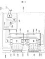
- FIG. 1 shows the overall configuration of Embodiment 1 of a battery monitoring device and a battery system using the same according to the present invention.
- the illustrated battery system 500 mainly includes an assembled battery group 200 in which a plurality of assembled batteries 21 and 22 are electrically connected in series, and a battery monitoring device 100 that monitors the assembled battery group 200. .
- the assembled batteries 21 and 22 constituting the assembled battery group 200 are each formed by connecting a plurality of battery cells 20 in series.
- Examples of the battery cell 20 include a lithium ion battery, a nickel metal hydride battery, a nickel cadmium battery, a lead battery, and a capacitor.
- the battery monitoring device 100 for example, the total voltage and current of the assembled battery group 200, the voltage and current of each of the assembled batteries 21 and 22 constituting the assembled battery group 200, each battery cell 20 forming the assembled battery 21 and 22 Voltage, current, temperature, monitoring the charging state and deterioration state of each battery cell 20 based on them, mainly a plurality of cell monitoring circuit boards 31, 32 connected to each assembled battery 21, 22, And an upper control circuit board (battery monitoring circuit board) 61 for controlling the cell monitoring circuit boards 31 and 32.
- the cell monitoring circuit boards 31 and 32 mainly include cell monitoring integrated circuits (first voltage detection circuits) 41 and 42 for monitoring the battery cells 20 forming the assembled batteries 21 and 22, respectively, and an upper control circuit board 61.
- Communication capacitors 52, 53, 54, 55 connected in series as communication interfaces with the microcomputer (second voltage detection circuit) 12 and other cell monitoring circuit boards.
- the integrated circuits 41 and 42 for example, detect the voltage of each battery cell 20 of the assembled batteries 21 and 22 connected to each integrated circuit 41 and 42 based on a command signal transmitted from the microcomputer 12 of the host control circuit board 61. Then, the detection result is transmitted to the outside.
- the host control circuit board 61 is mainly composed of a communication capacitor 51 connected in series as a communication interface with the power supply unit 10, the microcomputer 12, the total voltage detection unit 13, and the cell monitoring circuit boards 31 and 32. And have.
- the power supply unit 10 generates a voltage by supplying power from a lead storage battery 11 provided outside, and each circuit constituting the battery monitoring device 100 is operated by the voltage generated by the power supply unit 10. ing.
- the microcomputer 12 When measuring the voltage of each battery cell 20, the microcomputer 12 sends a command signal to the integrated circuits 41 and 42 mounted on the cell monitoring circuit boards 31 and 32 via the communication capacitor 51 as described above. Based on this command signal, the integrated circuits 41 and 42 measure the voltages of the battery cells 20 of the assembled batteries 21 and 22 connected to the integrated circuits 41 and 42. The measured voltage value of each battery cell 20 is temporarily stored in a register (not shown) provided in the integrated circuits 41 and 42, and the microcomputer 12 reads the measured voltage value of each battery cell 20 from the register. To obtain by communication.
- the communication line connecting the upper control circuit board 61 and each cell monitoring circuit board 31, 32 is a communication capacitor 51 mounted on the upper control circuit board 61 or each cell monitoring circuit board 31, 32. Since the connection to the outside of each board is made through 55 to 55, the communication line outside each board has a floating potential from the assembled battery group 200 and the lead storage battery 11.
- the microcomputer 12 when measuring the total voltage of the assembled battery group 200, the microcomputer 12 is connected to the positive side and the negative side of the assembled battery group 200 via the total voltage detection unit 13 having a predetermined circuit configuration connected to the microcomputer 12. The potential is acquired, and the total voltage of the assembled battery group 200 is measured by an A / D converter (not shown) provided in the microcomputer 12.
- the positive electrode side of the assembled battery group 200 is input to the upper control circuit board 61 via the total voltage detection resistor 121 mounted on the cell monitoring circuit board 31, and via the resistance group (for example, five) 127. Are connected to the input of the total voltage detector 13. Further, the negative electrode side of the assembled battery group 200 is connected to the upper control circuit board 61 via the total voltage detection resistors 125 and 126 mounted on the cell monitoring circuit board 32 and the total voltage detection resistance 123 mounted on the cell monitoring circuit board 31. And connected to the input unit of the total voltage detection unit 13 through a resistor group (for example, three) 128.
- a resistor group for example, three
- the positive electrode side of the assembled battery group 200 is connected to the input unit of the total voltage detector 13 via a positive electrode input line 13a (also referred to as a positive electrode input circuit), and via a negative electrode input line (also referred to as a negative electrode input circuit) 13b.
- a positive electrode input line 13a also referred to as a positive electrode input circuit
- a negative electrode input line also referred to as a negative electrode input circuit
- Connected to the input unit of the total voltage detection unit 13, and the positive input line 13a includes a total voltage detection resistor 121 mounted on the cell monitoring circuit board 31 and a positive electrode composed of a resistance group 127 mounted on the host control circuit board 61.
- the negative input line 13b is connected to the total voltage detection resistors 125 and 126 mounted on the cell monitoring circuit board 32, the total voltage detection resistance 123 mounted on the cell monitoring circuit board 31 and the upper control circuit board 61.
- a negative resistance composed of the mounted resistance group 128 is provided.
- the positive input line 13a and the negative input line 13b are equally divided in each line by the plurality of resistors mounted on the cell monitoring circuit boards 31 and 32 and the plurality of resistors mounted on the upper control circuit board 61. Is input to the total voltage detection unit 13 of the upper control circuit board 61, and the microcomputer 12 is connected to the positive side of the assembled battery group 200 via the positive input line 13a, the negative input line 13b, and the total voltage detection unit 13. By acquiring the potential on the negative electrode side, the total voltage of the assembled battery group 200 can be measured.
- the cell monitoring circuit boards 31 and 32 are arranged in a distributed manner. As a result, for some reason, for example, the connection lines connecting the cell monitoring circuit boards 31 and 32 on which the integrated circuits 41 and 42 are mounted and the upper control circuit board 61 on which the microcomputer 12 is mounted or the integrated circuits 41 and 42 are mounted. Even when the connection line connecting the cell monitoring circuit boards 31 and 32 is short-circuited, the current flowing through each battery cell 20 is suppressed by the total voltage detection resistors 123 and 126 mounted on the cell monitoring circuit boards 31 and 32. can do.
- each cell monitoring circuit board 31 and 32 is connected to the negative electrode side of the assembled battery 21 in order to improve the versatility of the cell monitoring circuit board as described below with reference to FIG.
- a total voltage detection resistor 122 and a total voltage detection resistor 124 connected to the positive electrode side of the assembled battery 22 are mounted. That is, since an insulating element as a communication interface is not mounted inside each cell monitoring circuit board 31, 32, and each cell monitoring circuit board 31, 32 has the same circuit configuration, a plurality of The cell monitoring circuit boards can be connected in series to easily form various battery systems.
- the upper control circuit board 61 is mounted with a ground fault detection unit 14 that detects a decrease in insulation between the microcomputer 12 of the upper control circuit board 61 and the integrated circuits 41 and 42 of the cell monitoring circuit boards 31 and 32.
- the ground fault detector 14 is connected to the positive input line 13a via the capacitor 56.
- the ground fault detection unit 14 may be connected to the negative input line 13b via the capacitor 56.
- the total voltage detection resistors 123 and 126 provided on the negative input line 13b that connects the negative side of the assembled battery group 200 and the total voltage detection unit 13 of the upper control circuit board 61 are as follows. At least one of the cell monitoring circuit boards, in particular, the cell monitoring circuit boards 31 and 32 are distributedly arranged. Thus, for example, the cell monitoring circuit boards 31 and 32 on which the integrated circuits 41 and 42 are mounted and the microcomputer 12 are mounted. Even when the connection line connecting the upper control circuit board 61 or the connection line connecting the cell monitoring circuit boards 31 and 32 on which the integrated circuits 41 and 42 are mounted is short-circuited, the current flowing through each battery cell 20 is reduced. The battery system 500 can be handled safely by an operator or the like.
- the number of resistors mounted on the upper control circuit board 61 is adjusted so that the number of resistors provided on the positive input line 13a and the negative input line 13b is the same.
- the positive voltage input line 13a and the negative electrode input line 13b are provided.
- the radix of the resistance to be generated may be different.
- the signal output from the cell monitoring circuit board 32 is input to the cell monitoring circuit board 32 again via the external loopback path.
- the loopback path outside 32 may be omitted, and the loopback path may be formed inside the cell monitoring circuit board 32 by selecting mounting of components.
- FIG. 2 shows the overall configuration of Embodiment 2 of the battery monitoring apparatus according to the present invention and a battery system using the same.
- the battery monitoring device 100A according to the second embodiment shown in FIG. 2 and the battery system 500A using the same are different from the first embodiment described above in that the total voltage detection resistors provided on the positive input line are distributed.
- Other configurations are almost the same as those of the first embodiment. Therefore, the same components as those in the first embodiment are denoted by the same reference numerals, and detailed description thereof is omitted.
- each cell monitoring circuit board of the battery monitoring device 100A has the same circuit configuration, various battery systems can be easily formed by changing the connection form of each cell monitoring circuit board. obtain.
- the cell monitoring circuit board 32A is connected to the upper assembled battery 21A of the assembled battery group 200A, and the cell monitoring circuit board 31A is connected to the lower assembled battery 22A of the assembled battery group 200A.
- the microcomputer 12A mounted on the host control circuit board 61A instructs the integrated circuits 41A and 42A mounted on the cell monitoring circuit boards 31A and 32A via the communication capacitor 51A. Based on this command signal, the integrated circuits 41A and 42A measure the voltages of the battery cells 20A of the assembled batteries 22A and 21A connected to the integrated circuits 41A and 42A. The measured voltage value of each battery cell 20A is temporarily stored in a register (not shown) provided in the integrated circuits 41A and 42A, and the microcomputer 12A reads the measured voltage value of each battery cell 20A from the register. To obtain by communication.
- the positive side of the assembled battery group 200A is mounted on the total voltage detection resistors 125A and 126A and the cell monitoring circuit board 31A mounted on the cell monitoring circuit board 32A.
- the voltage is input to the upper control circuit board 61A through the total voltage detection resistor 123A, and is connected to the input unit of the total voltage detection unit 13A through the resistor group (for example, three) 127A.
- the negative side of the assembled battery group 200A is input to the upper control circuit board 61A via the total voltage detection resistor 121A mounted on the cell monitoring circuit board 31A, and the total voltage is supplied via the resistance group (for example, five) 128A. It is connected to the input unit of the detection unit 13A.
- the positive electrode side of the assembled battery group 200A is connected to the input unit of the total voltage detecting unit 13A via the positive electrode input line 13aA (also referred to as a positive electrode input circuit), and the negative electrode side of the assembled battery group 200A is connected to the negative electrode input line 13bA.
- the positive input line 13aA includes total voltage detection resistors 125A and 126A mounted on the cell monitoring circuit board 32A, a cell monitoring circuit board
- a positive voltage resistor consisting of a total voltage detection resistor 123A mounted on 31A and a resistance group 127A mounted on the upper control circuit board 61A is provided, and a total voltage detection mounted on the cell monitoring circuit board 31A is provided on the negative input line 13bA.
- a negative resistance composed of a resistor 121A and a resistor group 128A mounted on the upper control circuit board 61A is provided.
- the positive input line 13aA and the negative input line 13bA are equally divided in each line by a plurality of resistors mounted on the cell monitoring circuit boards 31A and 32A and a plurality of resistors mounted on the upper control circuit board 61A. Is input to the total voltage detection unit 13A of the upper control circuit board 61A, and the microcomputer 12A communicates with the positive electrode side of the assembled battery group 200A via the positive input line 13aA, the negative input line 13bA, and the total voltage detection unit 13A. By acquiring the potential on the negative electrode side, the total voltage of the assembled battery group 200A can be measured.
- the total voltage detection resistor provided on the positive input line 13aA and the negative input line 13bA particularly the total voltage provided on the positive input line 13aA, for measuring the total voltage of the assembled battery group 200A.
- Detection resistors 123A and 126A are arranged in a distributed manner on the cell monitoring circuit boards 31A and 32A. Thereby, for some reason, for example, the connection lines connecting the cell monitoring circuit boards 31A and 32A on which the integrated circuits 41A and 42A are mounted and the upper control circuit board 61A on which the microcomputer 12A is mounted or the integrated circuits 41A and 42A are mounted.
- FIG. 3 shows the overall configuration of Embodiment 3 of the battery monitoring apparatus according to the present invention and a battery system using the same.
- the battery monitoring device 100B of Embodiment 3 and the battery system 500B using the same shown in FIG. 3 use one integrated circuit selected from a plurality of integrated circuits for cell monitoring as compared with Embodiments 1 and 2 described above.
- the configuration for detecting the total voltage of the assembled battery group is different, and the other configurations are substantially the same as those in the first and second embodiments. Therefore, about the structure similar to Embodiment 1, 2, the same code
- the total voltage detection unit 13B for measuring the total voltage of the assembled battery group 200B includes a plurality of cell monitoring circuit boards 31B and 32B.
- the total voltage of the assembled battery group 200B is measured by the integrated circuit 42B of the battery monitoring cell monitoring circuit board 32B provided in the integrated circuit 42B of the selected battery monitoring cell monitoring circuit board 32B.
- the battery monitoring device 100B mainly includes a plurality of cell monitoring circuit boards 31B and 32B connected to each of the assembled batteries 21B and 22B (as will be described later, the cell monitoring circuit board 32B includes a group of assembled batteries). And a high-order control circuit board 61B for controlling the cell monitoring circuit boards 31B and 32B.
- the cell monitoring circuit boards 31B and 32B are mainly integrated with cell monitoring integrated circuits (first voltage detection circuits) 41B and 42B for monitoring the battery cells 20B forming the assembled batteries 21B and 22B (integrated as will be described later).
- Circuit 42B also serves as the second voltage detection circuit), and communication capacitors 52B, 53B, 54B, 55B connected in series as a communication interface with the microcomputer 12B of the upper control circuit board 61B and other cell monitoring circuit boards, have.
- the integrated circuits 41B and 42B detect the voltage of each battery cell 20B of the assembled batteries 21B and 22B connected to each integrated circuit 41B and 42B based on a command signal transmitted from the microcomputer 12B of the host control circuit board 61B Then, the detection result is transmitted to the outside.
- the upper control circuit board 61B mainly has a power supply unit 10B, a microcomputer 12B, and a communication capacitor 51B connected in series as a communication interface with the cell monitoring circuit boards 31B and 32B.
- the microcomputer 12B When measuring the voltage of each battery cell 20B, the microcomputer 12B transmits a command signal to the integrated circuits 41B and 42B mounted on the cell monitoring circuit boards 31B and 32B via the communication capacitor 51B as described above. Based on this command signal, the integrated circuits 41B and 42B measure the voltages of the battery cells 20B of the assembled batteries 21B and 22B connected to the integrated circuits 41B and 42B. The measured voltage value of each battery cell 20B is temporarily stored in a register (not shown) provided in the integrated circuits 41B and 42B, and the microcomputer 12B reads the measured voltage value of each battery cell 20B from the register. To obtain by communication.
- the integrated circuit 42B of the cell monitoring circuit board (battery monitoring circuit board) 32B that monitors the battery cell having the lowest potential among the battery cells 20 of the assembled battery group 200B.
- the (second voltage detection circuit) acquires the positive and negative potentials of the assembled battery group 200B via the total voltage detection unit 13B having a predetermined circuit configuration provided therein, and the integrated circuit 42B
- the total voltage of the assembled battery group 200B is measured by an A / D converter (not shown) provided inside.
- the positive side of the assembled battery group 200B is connected to the total voltage detection resistors 121B and 123B mounted on the cell monitoring circuit board 31B and the total voltage detection resistors 126B and 125B mounted on the cell monitoring circuit board 32B.
- the divided voltage is connected to the input unit of the total voltage detection unit 13B of the integrated circuit 42B.
- the negative electrode side of the assembled battery group 200B is directly connected to the input unit of the total voltage detection unit 13B of the integrated circuit 42B.
- the positive electrode side of the assembled battery group 200B is connected to the input unit of the total voltage detection unit 13B via the positive electrode input line 13aB (also referred to as a positive electrode input circuit), and the negative electrode side of the assembled battery group 200B is connected to the negative electrode input line 13bB.
- the total voltage detection resistors 121B and 123B mounted on the cell monitoring circuit board 31B, and the total voltage mounted on the cell monitoring circuit board 32B A positive resistance composed of detection resistors 126B and 125B is provided.
- the integrated circuit 42B of the cell monitoring circuit board 32B acquires the positive and negative electrode potentials of the assembled battery group 200B via the positive input line 13aB, the negative input line 13bB, and the total voltage detection unit 13B. A total voltage of 200B can be measured.
- the total voltage detection resistors 123B and 126B provided on the positive input line 13aB for measuring the total voltage of the assembled battery group 200B are distributed to the cell monitoring circuit boards 31B and 32B. Has been placed. Thus, even if the connection lines connecting the cell monitoring circuit boards 31B and 32B on which the integrated circuits 41B and 42B are mounted are short-circuited for some reason, for example, the total mounted on each cell monitoring circuit board 31B and 32B The current flowing through each battery cell 20B can be suppressed by the voltage detection resistors 123B and 126B.
- the positive electrode side potential of the assembled battery group 200B is once output to the outside of the cell monitoring circuit board 31B and then input again to the cell monitoring circuit board 31B.
- the potential on the positive side of the assembled battery group 200B may be transmitted to the cell monitoring circuit board 32B via a connection line provided inside the board 31B.
- the negative electrode side of the assembled battery 21B is connected to the integrated circuit 42B of the lower cell monitoring circuit board 32B via the total voltage detection resistor 122B mounted on the cell monitoring circuit board 31B, and the assembled battery 21B , 22B may be used for voltage measurement for detecting an abnormal connection state.
- the total voltage detection resistors 123B and 126B provided on the positive input line 13aB for measuring the total voltage of the assembled battery group 200B are distributed and arranged on the cell monitoring circuit boards 31B and 32B.
- a plurality of total voltage detection resistors are provided on the negative electrode input line 13bB connecting the negative electrode side of the assembled battery group 200B and the total voltage detection unit 13B, and a plurality of total voltages provided on the negative electrode input line 13bB are provided.
- the voltage detection resistors may be arranged in a distributed manner on each cell monitoring circuit board 31B, 32B.
- the present invention is not limited to the first to third embodiments described above, and includes various modifications.
- the first to third embodiments described above are described in detail for easy understanding of the present invention, and are not necessarily limited to those having all the configurations described.
- a part of the configuration of an embodiment can be replaced with the configuration of another embodiment, and the configuration of another embodiment can be added to the configuration of an embodiment.
- each of the above-described configurations, functions, processing units, processing means, and the like may be realized by hardware by designing a part or all of them with, for example, an integrated circuit.
- Each of the above-described configurations, functions, and the like may be realized by software by interpreting and executing a program that realizes each function by the processor.
- Information such as programs, tables, and files for realizing each function can be stored in a recording device such as a memory, a hard disk, an SSD (Solid State Drive), or a recording medium such as an IC card, an SD card, or a DVD.
- control lines and information lines indicate what is considered necessary for the explanation, and not all the control lines and information lines on the product are necessarily shown. Actually, it may be considered that almost all the components are connected to each other.
Landscapes
- Engineering & Computer Science (AREA)
- Power Engineering (AREA)
- Life Sciences & Earth Sciences (AREA)
- Sustainable Development (AREA)
- Sustainable Energy (AREA)
- Transportation (AREA)
- Mechanical Engineering (AREA)
- Physics & Mathematics (AREA)
- General Physics & Mathematics (AREA)
- Secondary Cells (AREA)
- Charge And Discharge Circuits For Batteries Or The Like (AREA)
- Measurement Of Current Or Voltage (AREA)
Abstract
Description
図1は、本発明に係る電池監視装置及びそれを用いた電池システムの実施形態1の全体構成を示したものである。
図2は、本発明に係る本発明に係る電池監視装置及びそれを用いた電池システムの実施形態2の全体構成を示したものである。図2に示す実施形態2の電池監視装置100A及びそれを用いた電池システム500Aは、上記する実施形態1に対して正極入力線に設けられた総電圧検出抵抗を分散配置した構成が相違しており、その他の構成は実施形態1とほぼ同様である。したがって、実施形態1と同様の構成については、同様の符号を付してその詳細な説明は省略する。
図3は、本発明に係る本発明に係る電池監視装置及びそれを用いた電池システムの実施形態3の全体構成を示したものである。図3に示す実施形態3の電池監視装置100B及びそれを用いた電池システム500Bは、上記する実施形態1、2に対して複数のセル監視用集積回路から選択される一つの集積回路を用いて組電池群の総電圧を検出する構成が相違しており、その他の構成は実施形態1、2とほぼ同様である。したがって、実施形態1、2と同様の構成については、同様の符号を付してその詳細な説明は省略する。
11 鉛蓄電池
12 マイコン(第2電圧検出回路)
13 総電圧検出部
13a 正極入力線
13b 負極入力線
14 地絡検出部
20 電池セル
21、22 組電池
31、32 セル監視回路基板
32B バッテリ監視用セル監視回路基板(バッテリ監視回路基板)
41、42 セル監視用集積回路(第1電圧検出回路)
42B セル監視用集積回路(第2電圧検出回路)
51 上位制御回路基板の通信用コンデンサ
52、53、54、55 セル監視回路基板の通信用コンデンサ
56 コンデンサ
61 上位制御回路基板(バッテリ監視回路基板)
100 電池監視装置
121、122、123、124、125、126 総電圧検出抵抗
127、128 抵抗群
200 組電池群
500 電池システム
Claims (6)
- 複数の組電池が電気的に接続された組電池群を監視する電池監視装置であって、
該電池監視装置は、前記組電池を形成する各電池セルの電圧を検出する第1電圧検出回路がそれぞれに実装された複数のセル監視回路基板と、前記組電池群の総電圧を検出する第2電圧検出回路が実装されたバッテリ監視回路基板と、を備え、
前記第2電圧検出回路には、前記組電池群の正極側及び負極側と接続された総電圧検出部が接続されており、前記組電池群の正極側と前記総電圧検出部とを接続する正極入力線及び/又は前記組電池群の負極側と前記総電圧検出部とを接続する負極入力線には少なくとも一つの抵抗が設けられ、前記正極入力線及び/又は前記負極入力線の前記抵抗は、前記複数のセル監視回路基板の少なくとも一つに配置されていることを特徴とする電池監視装置。 - 前記正極入力線及び/又は前記負極入力線の前記抵抗は、前記複数のセル監視回路基板のそれぞれに分散配置されていることを特徴とする、請求項1に記載の電池監視装置。
- 複数の組電池が電気的に接続された組電池群を監視する電池監視装置であって、
該電池監視装置は、前記組電池を形成する各電池セルの電圧を検出する集積回路がそれぞれに実装された複数のセル監視回路基板と、前記組電池群の総電圧を検出するマイコンが実装された上位制御回路基板と、を備え、
前記マイコンには、前記組電池群の正極側及び負極側と接続された総電圧検出部が接続されており、前記組電池群の正極側と前記総電圧検出部とを接続する正極入力線及び/又は前記組電池群の負極側と前記総電圧検出部とを接続する負極入力線には少なくとも一つの抵抗が設けられ、前記正極入力線及び/又は前記負極入力線の前記抵抗は、前記複数のセル監視回路基板の少なくとも一つに配置されていることを特徴とする電池監視装置。 - 複数の組電池が電気的に接続された組電池群を監視する電池監視装置であって、
該電池監視装置は、前記組電池を形成する各電池セルの電圧を検出する集積回路がそれぞれに実装された複数のセル監視回路基板を備え、該複数のセル監視回路基板から選択されたバッテリ監視用セル監視回路基板が、実装された集積回路によって組電池群の総電圧を検出するようになっており、
前記バッテリ監視用セル監視回路基板の集積回路には、前記組電池群の正極側及び負極側と接続された総電圧検出部が設けられており、前記組電池群の正極側と前記総電圧検出部とを接続する正極入力線又は前記組電池群の負極側と前記総電圧検出部とを接続する負極入力線には少なくとも一つの抵抗が設けられ、前記正極入力線又は前記負極入力線の前記抵抗は、前記複数のセル監視回路基板の少なくとも一つに配置されていることを特徴とする電池監視装置。 - 前記バッテリ監視用セル監視回路基板は、前記組電池群の最上位の電位を有する電池セルの電圧を検出する集積回路が実装されたセル監視回路基板、もしくは、前記組電池群の最下位の電位を有する電池セルの電圧を検出する集積回路が実装されたセル監視回路基板であることを特徴とする、請求項4に記載の電池監視装置。
- 請求項1に記載の電池監視装置と、該電池監視装置の各セル監視回路基板に接続された複数の組電池からなる組電池群と、を備えたことを特徴とする電池システム。
Priority Applications (5)
| Application Number | Priority Date | Filing Date | Title |
|---|---|---|---|
| PCT/JP2013/062394 WO2014174669A1 (ja) | 2013-04-26 | 2013-04-26 | 電池監視装置及びそれを用いた電池システム |
| CN201380075926.0A CN105164541B (zh) | 2013-04-26 | 2013-04-26 | 电池监视装置和使用该电池监视装置的电池系统 |
| US14/784,440 US10788539B2 (en) | 2013-04-26 | 2013-04-26 | Battery monitoring device and battery system using same |
| JP2015513462A JP5997371B2 (ja) | 2013-04-26 | 2013-04-26 | 電池監視装置及びそれを用いた電池システム |
| EP13882790.2A EP2990812B1 (en) | 2013-04-26 | 2013-04-26 | Battery monitoring device and battery system using same |
Applications Claiming Priority (1)
| Application Number | Priority Date | Filing Date | Title |
|---|---|---|---|
| PCT/JP2013/062394 WO2014174669A1 (ja) | 2013-04-26 | 2013-04-26 | 電池監視装置及びそれを用いた電池システム |
Publications (1)
| Publication Number | Publication Date |
|---|---|
| WO2014174669A1 true WO2014174669A1 (ja) | 2014-10-30 |
Family
ID=51791273
Family Applications (1)
| Application Number | Title | Priority Date | Filing Date |
|---|---|---|---|
| PCT/JP2013/062394 WO2014174669A1 (ja) | 2013-04-26 | 2013-04-26 | 電池監視装置及びそれを用いた電池システム |
Country Status (5)
| Country | Link |
|---|---|
| US (1) | US10788539B2 (ja) |
| EP (1) | EP2990812B1 (ja) |
| JP (1) | JP5997371B2 (ja) |
| CN (1) | CN105164541B (ja) |
| WO (1) | WO2014174669A1 (ja) |
Families Citing this family (10)
| Publication number | Priority date | Publication date | Assignee | Title |
|---|---|---|---|---|
| JP5850017B2 (ja) * | 2013-10-15 | 2016-02-03 | 株式会社デンソー | バッテリ監視装置 |
| US9592738B1 (en) | 2015-10-30 | 2017-03-14 | Faraday&Future Inc. | Serial communication safety controller |
| CN105891656B (zh) * | 2016-04-19 | 2019-02-12 | 北京长城华冠汽车科技股份有限公司 | 一种动力电池系统故障检测方法及装置 |
| US11201614B2 (en) * | 2017-07-19 | 2021-12-14 | Hitachi Automotive Systems, Ltd. | Load control device having multiple terminals and a clamp circuit connected therebetween |
| KR102256094B1 (ko) * | 2017-11-28 | 2021-05-25 | 주식회사 엘지에너지솔루션 | 배터리 팩 |
| CN108016315A (zh) * | 2017-12-05 | 2018-05-11 | 广州魔动新能源科技有限公司 | 一种充换电站的安全防护方法、系统及终端设备 |
| JP7077204B2 (ja) * | 2018-10-31 | 2022-05-30 | 株式会社豊田中央研究所 | 電源装置 |
| CN113655389B (zh) * | 2020-05-12 | 2022-10-18 | 比亚迪股份有限公司 | 诊断电池包动力回路连接状态的方法和系统、存储介质、电池管理系统和车辆 |
| KR102639780B1 (ko) * | 2021-10-14 | 2024-02-21 | 엘지전자 주식회사 | 에너지 저장장치 |
| EP4439089A1 (en) * | 2023-03-27 | 2024-10-02 | Prime Planet Energy & Solutions, Inc. | Voltage measurement circuit board and electricity storage system |
Citations (5)
| Publication number | Priority date | Publication date | Assignee | Title |
|---|---|---|---|---|
| JP2009236711A (ja) | 2008-03-27 | 2009-10-15 | Hitachi Ltd | 組電池の総電圧検出回路 |
| JP2010011631A (ja) * | 2008-06-26 | 2010-01-14 | Sanyo Electric Co Ltd | 電源装置 |
| JP2010145128A (ja) * | 2008-12-16 | 2010-07-01 | Denso Corp | 組電池の監視装置 |
| JP2010228523A (ja) | 2009-03-26 | 2010-10-14 | Hitachi Ltd | 車両用電池システム |
| JP2011041422A (ja) * | 2009-08-17 | 2011-02-24 | Hitachi Ltd | 組電池制御装置 |
Family Cites Families (43)
| Publication number | Priority date | Publication date | Assignee | Title |
|---|---|---|---|---|
| DE9415874U1 (de) | 1994-09-29 | 1994-12-08 | Volkswagen Ag, 38440 Wolfsburg | Batterie-Prüfleitung in einem Elektrofahrzeug |
| US6014012A (en) * | 1998-07-28 | 2000-01-11 | Ntt Power And Building Facilities Inc. | Apparatus for managing a battery unit having storage batteries |
| US6420852B1 (en) * | 1998-08-21 | 2002-07-16 | Sony Corporation | Battery pack |
| JP3300309B2 (ja) * | 1999-10-19 | 2002-07-08 | 本田技研工業株式会社 | 電池電圧測定装置 |
| US6417648B2 (en) * | 2000-06-28 | 2002-07-09 | Nissan Motor Co., Ltd. | Method of and apparatus for implementing capacity adjustment in battery pack |
| FR2825842B1 (fr) * | 2001-06-07 | 2003-10-03 | Cit Alcatel | Procede d'equilibrage pour batterie electrique sousmise a un regime discontinu de recharge et systeme de gestion de batterie permettant la mise en oeuvre de ce procede |
| JP4605952B2 (ja) * | 2001-08-29 | 2011-01-05 | 株式会社日立製作所 | 蓄電装置及びその制御方法 |
| FR2852149B1 (fr) * | 2003-03-04 | 2005-04-08 | Cit Alcatel | Dispositif et procede perfectionnes de controle de tension de generateurs electrochimiques de batterie rechargeable |
| JP2007520180A (ja) * | 2003-10-14 | 2007-07-19 | ブラック アンド デッカー インク | 電池パックの障害状態からの保護を提供するべく適合された二次電池、電動工具、充電器、及び電池パック用の保護方法、保護回路、及び保護装置 |
| JP2005318751A (ja) * | 2004-04-30 | 2005-11-10 | Shin Kobe Electric Mach Co Ltd | 多直列電池制御システム |
| JP4290085B2 (ja) * | 2004-07-09 | 2009-07-01 | 三洋電機株式会社 | 電源回路 |
| US7417405B2 (en) * | 2004-10-04 | 2008-08-26 | Black & Decker Inc. | Battery monitoring arrangement having an integrated circuit with logic controller in a battery pack |
| JP4506606B2 (ja) * | 2005-07-28 | 2010-07-21 | 日産自動車株式会社 | 組電池の電圧検出装置 |
| US7656131B2 (en) * | 2005-10-31 | 2010-02-02 | Black & Decker Inc. | Methods of charging battery packs for cordless power tool systems |
| KR100991084B1 (ko) * | 2005-12-15 | 2010-10-29 | 주식회사 엘지화학 | 멀티 전지 팩 시스템 및 그 제어방법, 및 이를 이용한 전지팩 |
| JP4490931B2 (ja) | 2006-02-09 | 2010-06-30 | 矢崎総業株式会社 | 電圧検出装置 |
| JP4508145B2 (ja) * | 2006-04-10 | 2010-07-21 | 株式会社デンソー | 組電池の管理装置 |
| US7352155B2 (en) * | 2006-06-12 | 2008-04-01 | O2Micro International Ltd. | Apparatus and method for detecting battery pack voltage |
| JP4241787B2 (ja) * | 2006-09-06 | 2009-03-18 | 日立ビークルエナジー株式会社 | 組電池総電圧検出およびリーク検出装置 |
| US7859223B2 (en) * | 2007-01-31 | 2010-12-28 | Analog Devices, Inc. | Battery montoring apparatus and daisy chain interface suitable for use in a battery monitoring apparatus |
| JP4722067B2 (ja) * | 2007-03-06 | 2011-07-13 | 日立ビークルエナジー株式会社 | 蓄電装置,蓄電池管理制御装置及びモータ駆動装置 |
| JP5254568B2 (ja) * | 2007-05-16 | 2013-08-07 | 日立ビークルエナジー株式会社 | セルコントローラ、電池モジュールおよび電源システム |
| JP5060857B2 (ja) * | 2007-07-19 | 2012-10-31 | 日立ビークルエナジー株式会社 | セルコントローラ |
| JP5560557B2 (ja) * | 2008-02-27 | 2014-07-30 | 日産自動車株式会社 | 組電池の制御装置 |
| JP5529402B2 (ja) * | 2008-08-13 | 2014-06-25 | 三菱重工業株式会社 | 蓄電システム |
| JP5221468B2 (ja) * | 2009-02-27 | 2013-06-26 | 株式会社日立製作所 | 電池監視装置 |
| JP2010257750A (ja) * | 2009-04-24 | 2010-11-11 | Sanyo Electric Co Ltd | バッテリモジュール、バッテリシステムおよび電動車両 |
| JP5390951B2 (ja) * | 2009-06-19 | 2014-01-15 | 矢崎総業株式会社 | 複数組電池の電圧測定装置 |
| JP2011072153A (ja) * | 2009-09-28 | 2011-04-07 | Sanyo Electric Co Ltd | 車両用電源装置及びこれを備える車両並びに車両用電源装置の容量均等化方法 |
| JP5333126B2 (ja) * | 2009-09-29 | 2013-11-06 | 株式会社デンソー | 組電池制御装置 |
| EP2325919A3 (en) | 2009-10-30 | 2011-11-30 | Sanyo Electric Co., Ltd. | Battery system and electric vehicle including the same |
| JP2011155829A (ja) * | 2009-12-28 | 2011-08-11 | Sanyo Electric Co Ltd | バッテリシステムおよびそれを備えた電動車両 |
| JP5470073B2 (ja) * | 2010-02-05 | 2014-04-16 | 日立ビークルエナジー株式会社 | 電池制御装置および電池システム |
| JP5556354B2 (ja) * | 2010-05-18 | 2014-07-23 | スズキ株式会社 | 電力供給回路の制御装置 |
| JP5584927B2 (ja) * | 2010-06-04 | 2014-09-10 | 日立オートモティブシステムズ株式会社 | 電池制御装置および蓄電装置 |
| JP5353915B2 (ja) * | 2011-02-01 | 2013-11-27 | 株式会社デンソー | 電池電圧監視装置 |
| WO2012164761A1 (ja) * | 2011-05-31 | 2012-12-06 | 日立ビークルエナジー株式会社 | 電池システム監視装置 |
| JP5844106B2 (ja) | 2011-09-28 | 2016-01-13 | 三洋電機株式会社 | 車両用の電源装置とこの電源装置を備える車両 |
| JP5677261B2 (ja) | 2011-09-30 | 2015-02-25 | 株式会社日立製作所 | 蓄電システム |
| JP5230789B2 (ja) * | 2011-11-25 | 2013-07-10 | 三菱重工業株式会社 | 電池システム |
| US8922165B2 (en) * | 2012-05-14 | 2014-12-30 | Freescale Semiconductor, Inc. | Cell balance configuration for pin count reduction |
| US9203118B2 (en) * | 2013-04-09 | 2015-12-01 | GM Global Technology Operations LLC | Capacitive communication layer for cell integrated battery management system |
| JP5902136B2 (ja) * | 2013-09-17 | 2016-04-13 | 株式会社東芝 | 電池監視装置および電池監視システム |
-
2013
- 2013-04-26 WO PCT/JP2013/062394 patent/WO2014174669A1/ja active Application Filing
- 2013-04-26 US US14/784,440 patent/US10788539B2/en active Active
- 2013-04-26 JP JP2015513462A patent/JP5997371B2/ja active Active
- 2013-04-26 CN CN201380075926.0A patent/CN105164541B/zh active Active
- 2013-04-26 EP EP13882790.2A patent/EP2990812B1/en active Active
Patent Citations (5)
| Publication number | Priority date | Publication date | Assignee | Title |
|---|---|---|---|---|
| JP2009236711A (ja) | 2008-03-27 | 2009-10-15 | Hitachi Ltd | 組電池の総電圧検出回路 |
| JP2010011631A (ja) * | 2008-06-26 | 2010-01-14 | Sanyo Electric Co Ltd | 電源装置 |
| JP2010145128A (ja) * | 2008-12-16 | 2010-07-01 | Denso Corp | 組電池の監視装置 |
| JP2010228523A (ja) | 2009-03-26 | 2010-10-14 | Hitachi Ltd | 車両用電池システム |
| JP2011041422A (ja) * | 2009-08-17 | 2011-02-24 | Hitachi Ltd | 組電池制御装置 |
Non-Patent Citations (1)
| Title |
|---|
| See also references of EP2990812A4 |
Also Published As
| Publication number | Publication date |
|---|---|
| EP2990812A4 (en) | 2017-01-11 |
| US20160169976A1 (en) | 2016-06-16 |
| JP5997371B2 (ja) | 2016-09-28 |
| CN105164541A (zh) | 2015-12-16 |
| JPWO2014174669A1 (ja) | 2017-02-23 |
| US10788539B2 (en) | 2020-09-29 |
| CN105164541B (zh) | 2018-04-06 |
| EP2990812A1 (en) | 2016-03-02 |
| EP2990812B1 (en) | 2022-08-03 |
Similar Documents
| Publication | Publication Date | Title |
|---|---|---|
| JP5997371B2 (ja) | 電池監視装置及びそれを用いた電池システム | |
| JP5447260B2 (ja) | 電池電圧監視装置 | |
| JP5670556B2 (ja) | 電池制御装置 | |
| US10649040B2 (en) | Leakage current determination | |
| JP5747900B2 (ja) | 電池監視装置 | |
| US20150229144A1 (en) | Battery management system | |
| JP2010187534A (ja) | セルのバランスをとるための回路及び方法 | |
| WO2015072510A1 (ja) | 蓄電池、蓄電池の制御方法及びプログラム | |
| KR20200091466A (ko) | 배터리의 셀 밸런싱 | |
| JP2012208066A (ja) | 電池電圧検出装置 | |
| CN107407707B (zh) | 异常检测装置 | |
| JP7401058B2 (ja) | 絶縁抵抗測定回路及び診断方法 | |
| JP2018117438A (ja) | リチウムイオンキャパシタを備えた電源モジュール | |
| JP6192588B2 (ja) | 電池監視装置 | |
| JP6018169B2 (ja) | 蓄電装置の故障判定方法 | |
| KR20140124470A (ko) | 배터리 제어 시스템 및 그의 구동 방법 | |
| JP2016029349A (ja) | 電池監視回路 | |
| JP6034031B2 (ja) | 二次電池装置 | |
| Tarle et al. | Design of a battery management system for formula Student electric race vehicle | |
| JP2016161357A (ja) | 電源監視装置および電源監視方法 | |
| JP2014106145A (ja) | 電池監視装置 | |
| JP2014134488A (ja) | 電池監視装置 | |
| JP2024088578A (ja) | バッテリー管理方法、およびこれを行うバッテリー管理装置およびバッテリーパック | |
| US20200152947A1 (en) | Battery System Monitoring Device and Battery Pack | |
| CN113557440A (zh) | 电池装置和电流传感器诊断方法 |
Legal Events
| Date | Code | Title | Description |
|---|---|---|---|
| WWE | Wipo information: entry into national phase |
Ref document number: 201380075926.0 Country of ref document: CN |
|
| 121 | Ep: the epo has been informed by wipo that ep was designated in this application |
Ref document number: 13882790 Country of ref document: EP Kind code of ref document: A1 |
|
| ENP | Entry into the national phase |
Ref document number: 2015513462 Country of ref document: JP Kind code of ref document: A |
|
| WWE | Wipo information: entry into national phase |
Ref document number: 14784440 Country of ref document: US |
|
| WWE | Wipo information: entry into national phase |
Ref document number: 2013882790 Country of ref document: EP |
|
| NENP | Non-entry into the national phase |
Ref country code: DE |