WO2014168196A1 - 筆記具 - Google Patents
筆記具 Download PDFInfo
- Publication number
- WO2014168196A1 WO2014168196A1 PCT/JP2014/060372 JP2014060372W WO2014168196A1 WO 2014168196 A1 WO2014168196 A1 WO 2014168196A1 JP 2014060372 W JP2014060372 W JP 2014060372W WO 2014168196 A1 WO2014168196 A1 WO 2014168196A1
- Authority
- WO
- WIPO (PCT)
- Prior art keywords
- writing
- refill
- view
- writing instrument
- tip
- Prior art date
- Legal status (The legal status is an assumption and is not a legal conclusion. Google has not performed a legal analysis and makes no representation as to the accuracy of the status listed.)
- Ceased
Links
Images











Classifications
-
- B—PERFORMING OPERATIONS; TRANSPORTING
- B43—WRITING OR DRAWING IMPLEMENTS; BUREAU ACCESSORIES
- B43K—IMPLEMENTS FOR WRITING OR DRAWING
- B43K7/00—Ball-point pens
- B43K7/12—Ball-point pens with retractable ball points
-
- B—PERFORMING OPERATIONS; TRANSPORTING
- B43—WRITING OR DRAWING IMPLEMENTS; BUREAU ACCESSORIES
- B43K—IMPLEMENTS FOR WRITING OR DRAWING
- B43K1/00—Nibs; Writing-points
- B43K1/08—Nibs; Writing-points with ball points; Balls or ball beds
- B43K1/086—Nibs; Writing-points with ball points; Balls or ball beds with resilient supporting means for the ball, e.g. springs
-
- B—PERFORMING OPERATIONS; TRANSPORTING
- B43—WRITING OR DRAWING IMPLEMENTS; BUREAU ACCESSORIES
- B43K—IMPLEMENTS FOR WRITING OR DRAWING
- B43K24/00—Mechanisms for selecting, projecting, retracting or locking writing units
- B43K24/02—Mechanisms for selecting, projecting, retracting or locking writing units for locking a single writing unit in only fully projected or retracted positions
-
- B—PERFORMING OPERATIONS; TRANSPORTING
- B43—WRITING OR DRAWING IMPLEMENTS; BUREAU ACCESSORIES
- B43K—IMPLEMENTS FOR WRITING OR DRAWING
- B43K25/00—Attaching writing implements to wearing apparel or objects involving constructional changes of the implements
- B43K25/02—Clips
Definitions
- the present invention relates to a writing instrument capable of suppressing stick-slip in writing and improving writing taste.
- a writing instrument which is provided with a buffer element at the tip of a knock button to press a refill, and responds to the pressure applied during writing (see JP-A-2006-520281: Patent Document 1).
- Patent Literature 2 Japanese Patent Publication 2009-542466: Patent Literature 2.
- the writing line when sebum is on the paper, in a writing instrument such as a ballpoint pen, the writing line may be interrupted by the sliding of the ball on the paper.
- the core In this mechanical pencil, the core is rotated under a constant load in order to prevent the writing track from becoming thicker, thinner, or the line width becoming unstable due to wear, but the structure is relatively complex. It is. In addition, it is not a structure that can change the amount of rotation of the core according to the writing load, and even if it is used for a ballpoint pen or the like, it is not a technology that can prevent the writing line from breaking when sebum gets on the paper.
- the present invention is intended to provide a writing instrument in which a desired writing taste can be obtained by rotating the refill with a simple configuration.
- the present invention relates to a writing instrument in which a refill in which a writing unit and an ink storage unit are integrally provided is accommodated in a shaft cylinder, It is a writing instrument characterized in that the refill rotates around an axis when the writing load to the back is given to the refill.
- a twist member be disposed in the refill or the shaft cylinder for rotating the refill about the axis by writing load.
- a torsion member for rotating around the refill axis is attached to the refill.
- the angle at which the refill rotates at a writing load of 3 N is 1 degree or more.
- the present invention is a knock type ballpoint pen which can slide the refill back and forth.
- the torsion member comprises a generally cylindrical main body to be attached to the refill, and a plurality of columnar portions at either or both ends in the axial direction of the main body, and the plurality of columnar portions are While being formed inclining in the circumferential direction centering on the axis of said refill, It is preferable that, in the torsion member, the columnar portion is inclined in the inclined direction by writing pressure so that the refill and the shaft cylinder rotate relative to each other.
- the torsion member is formed of a generally cylindrical main body attached to the refill, and an axially continuous elastic compression portion of the main body,
- the elastic compression portion is a portion in which a groove or a hole is formed in a part of the outer diameter,
- the elastically compressed portion is deformed by the writing load to rotate the refill and the shaft cylinder relative to each other.
- the refill rotates about the axial center when a backward writing load is applied to the refill.
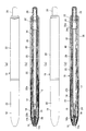
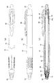
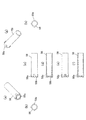
- FIG. 1A is a front view
- FIG. 2B is a perspective view from the front
- FIG. 2C is a side view
- FIG. 2D is the same state as FIG. 1C.
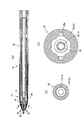
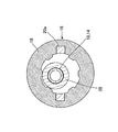
- FIG. 6 is an operation explanatory view around the front axis in the writing state at the time of knocking in the writing instrument of FIG. 1, and is a cross-sectional view taken along the line L-L in FIG. 5 (a).
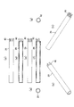
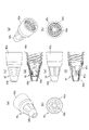
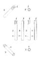
- FIG. 7 is an explanatory view of a front axis in the writing instrument, where (a) is a perspective view from the front, (b) is a front view, (c) is a side view, and (d) is a longitudinal cross section in the same state as (c) (E) is another side view rotated 90 degrees from (c), (f) is a longitudinal sectional view in the same state as (e), (g) is a perspective view from the rear, (h) is a rear view FIG. It is explanatory drawing of the front axis periphery in the non-writing state at the time of knocking in the writing instrument of FIG.
- FIG. 7 is an operation explanatory view at the time of writing when the writing instrument of FIG. 7 is knocked, and is a cross-sectional view taken along the PP line of FIG. 10 (c).
- FIG. 12 is an explanatory view of a base in the writing instrument, where (a) is a view from the front, (b) is a side view, (c) is a longitudinal cross section in the same state as (b), (d) is a view from the rear FIG.
- FIG. 14 It is explanatory drawing of the inner cylinder of the writing instrument of FIG. 14, (a) is a perspective view from the front, (b) is a front view, (c) is a side view, (d) is a longitudinal cross section of the same state as (c). , (E) is a perspective view from the rear, and (f) is a rear view. It is an explanatory view of a knock bar in the writing instrument of FIG. 14, (a) is a perspective view from the front, (b) is a front view, (c) is a side view, and (d) is a longitudinal cross section in the same state as (c).
- FIG. 14 is an explanatory view of a rotor in the writing instrument of FIG. 14, in which (a) is a perspective view from the front, (b) is a front view, (c) is a side view, and (d) is a longitudinal sectional view in the same state as (c) (E) is another side view rotated 90 degrees from (c), (f) is a longitudinal sectional view in the same state as (e), (g) is a perspective view from the rear, (h) is the rear FIG.
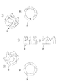
- FIG. 14 is an explanatory view of a torsion joint in the writing instrument of FIG. 14, where (a) is a perspective view from the front, (b) is a front view, (c) is a side view, and (d) is an angle from (c) The side view changed, (e) is a perspective view from the rear, and (f) is a rear view.
- FIG. 1 is a perspective view from the front
- (b) is a side view
- (c) is a longitudinal cross section in the same state as (b)
- (d) is a rear view. It is. It is an explanatory view at the time of a knock of a writing instrument concerning a 6th embodiment of the present invention, and (a) is one side view, (b) is a whole longitudinal section in the same state as (a), (c) is (a) And (d) is a longitudinal sectional view in the same state as (c).
- FIG. 22 is an explanatory view of a front axis in the writing instrument, where (a) is a perspective view from the front, (b) is a front view, (c) is a side view, and (d) is a longitudinal cross section in the same state as (c). (E) is another side view rotated 90 degrees from (c), (f) is a longitudinal sectional view in the same state as (e), (g) is a perspective view from the rear, (h) is a rear view FIG. 22 is an explanatory view of a torsion joint in the writing instrument of FIG.
- (D) is another side view rotated 90 degrees from (b)
- (e) is a longitudinal sectional view in the same state as (d)
- (f) is a perspective view from the rear.
- (a) is a perspective view from the front
- (b) is a front view
- (c) is one side view
- (d) is.
- (e) is another side view rotated 90 degrees from (c)
- (f) is a longitudinal sectional view in the same state as (e)
- (g) is from the rear
- (h) is a rear view.
- (D) is another side view rotated 90 degrees from (b), (e) is a longitudinal sectional view in the same state as (d), and (f) is a perspective view from the rear.
- (a) is a perspective view from the front
- (b) is a side view
- (c) is a longitudinal cross section of the same state as (b).
- (D) is another side view rotated 90 degrees from (b)
- (e) is a longitudinal sectional view in the same state as (d)
- (f) is a perspective view from the rear.
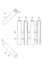
- FIG. 6 is an explanatory view of the writing track of ink due to stick-slip, in which (a) is a conventional product A, (b) is a first to sixth embodiment product, (c) is a conventional product B, (d) is a sixth, FIG. 16 is an explanatory view of the writing locus of each of the ninth to twelfth embodiment articles and (e) of the first, fourth and sixth to eighth embodiment articles.
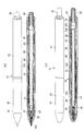
- FIG. 1 is an explanatory view at the time of non-knocking of the writing tool
- FIG. 2 is an explanatory view at the time of knocking
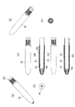
- FIG. 3 is an explanatory view of a tip axis of the writing tool
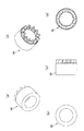
- FIG. 4 is an explanatory view of a torsion joint of the writing tool
- FIG. 6 is action
- the writing instrument according to the first embodiment relates to a writing instrument in which a refill 14 in which a writing unit 10 and an ink storage unit 12 are integrally provided is accommodated in a barrel 16 as shown in FIG.
- the front side of the refill 14 is separated from the inner surface of the barrel 16 at the time of unwriting, while it is in contact with the inner surface of the barrel 16 by the writing load at the time of writing.
- the hollow shaft cylinder 16 is a united shaft cylinder 16 in which a front shaft 20 at the center and a rear shaft 22 at the rear from the center are screwed to each other. Are configured.
- a stepped portion 20 b is formed on the inner surface of the tip end portion of the front shaft 20, and a spring 24 is engaged with the stepped portion 20 b and mounted in the front shaft 20.
- the refill 14 is urged rearward by the spring 24.
- the outer diameter of the ink containing portion 12 of the main body portion is larger than the outer diameter of the writing portion 10 at the tip end of the refill 14.
- the writing unit 10 at the tip of the refill 14 is a ballpoint pen tip, and is a writing tool of a knock type ballpoint pen provided with a knocking bar 26 at the rear end of the refill 14.
- a torsion joint 28 and a torsion joint receiver 30 having a flat front surface facing the rear portion are covered.
- An inner cylinder 32 is fitted and fixed in the rear end portion of the rear shaft 22, and a knocking rotor 34 that is in contact with the rear end of the torsion joint receiver 30 is mounted in the inner cylinder 32.
- Long and short notches 32 a are formed in the circumferential direction at the tip of the inner cylinder 32 in the axial direction. Further, a projection 34 a is formed to protrude in the outer diameter direction on the outer periphery of the tip of the knocking rotor 34.
- a spring 36 for knocking is interposed between the flange projections formed on the torsion joint receiving body 30 and the rear shaft 22.
- the spring 36 makes the rotor 34 and the knocking rod 26 an axial cylinder. It is biased rearward with respect to 16 (rear shaft 22).
- the protrusion 34 a on the outer periphery of the tip of the rotor 34 is notched at the tip of the inner cylinder 32 by pressing release.
- the writing unit 10 protruding state (writing state) of the refill 14 is maintained.
- the protrusion 34a on the tip outer periphery of the rotor 34 is disengaged from the short one of the tip notch 32a of the inner cylinder 32 and is rotated
- the long tip end notch is fitted to 32a, and the writing unit 10 of the refill 14 maintains the immersive state (the non-writing state).
- the writing unit 10 at the tip is connected to the tip of the ink storage unit 12 via the joint 38.
- the writing unit 10 is a ballpoint pen tip provided with a ball 10a at the tip of the main body, and an interior spring 10b is provided to press the ball 10a in the ink flow path inside.
- the main body of the writing unit 10 is substantially cylindrical, the rear end is open, and the interior spring protrudes rearward.
- the joint 38 has a substantially hollow cylindrical shape, and the inner diameter is narrowed at the central portion in the axial direction, and the rear end of the inner spring 10b is in contact with and supported by the small diameter portion. Further, the rear end of the joint 38 is expanded in a stepwise manner to form a double cylinder structure including an inner cylinder and an outer cylinder, and the double cylinder structure of the rear end is at the front end of the ink accommodating portion 12 of the resin tube. It is worn so as to wrap in and out.
- the outer diameter of the joint 38 other than the rear end portion is larger than that of the writing portion 10 and smaller than the outer diameter of the ink containing portion 12 so as to increase in diameter stepwise.
- the spring 24 is encased in the joint 38, and the front end of the spring 24 abuts on the stepped portion 20b of the front shaft 20 mentioned above and the rear end comes in contact with the step-expanded portion of the joint 38 and the spring 14 applies the refill 14 rearward. I'm upset.
- the front shaft 20 is a grip portion 18 in which the inner main body 20 a is a hard resin material and covered by a rubber elastic material on the outer peripheral surface.
- An external thread is formed on the outer periphery of the rear end portion of the front shaft 20, and a notch 20c is cut out so as to extend from the rear end edge to the start portion of the external thread and one turn.
- the notch 20c can prevent the rear shaft 22 (see FIG. 1) from being broken.
- a plurality of windows are opened on the side surface at the tip of the inner main body 20a.
- the rubber elastic material of the grip 18 is formed earlier than the tip of the inner main body 20a and protrudes inward from the window (see FIG. 5).
- the grip 18 of the rubber elastic material is formed prior to the tip of the inner main body 20a, the grip 18 forms the tip of the front shaft 20 and protrudes inward, as shown in FIG. 5 (b).
- the gap between the outer circumference of the writing unit 10 and the inner circumference at the tip of the tip shaft 20 is small, and as shown in FIG.
- the gap with the inner surface is large, and the rear side is larger than the position at which the inner surface of the barrel 16 is first hit by the writing load at the time of writing.
- the inner surface of the front shaft 20 which contacts the refill 14 is formed of a rubber elastic material.
- the rubber elastic material is formed on the grip portion 18 of the outer surface of the front shaft 20, and is also formed to protrude on the inner surface of the front shaft 20.
- a rubber elastic material is formed on the tip end portion and the middle portion of the tip shaft 20 of the barrel 16 so as to face the inner surface, and the refill 14 is in contact with the rubber elastic material at the tip portion and the middle portion of the barrel 16 by writing load when writing. It is something which is made to touch.
- the front shaft 20 is formed by two-color molding of the grip 18 of the rubber elastic material and the inner main body 20 a made of a hard material.
- two-color molding is preferable, another method may be used in which another molding is integrated by bonding, fitting or the like.
- thermoplastic elastomer various materials such as thermoplastic elastomer, natural rubber and synthetic rubber can be suitably used.
- hard material of the inner main body 20a resin materials such as ABS, PC, PBT, PP, PET, PMMA (acrylic resin), COC (cyclic olefin resin) and the like can be suitably used.
- the writing conditions to be in contact can be set to a load of 3 N or more and an angle of the writing unit to the writing surface of 60 degrees.
- the torsion joint 28 is a hollow shaft-like member that is encased by the refill 14 in the shaft cylinder 16, and the tip end face of the torsion joint 28 is a joint 38 of the refill 14 ( It is arrange
- the front end of a hollow cylindrical main body made of a hard resin material is formed flat, and a rotary drive unit 40 made of a rubber elastic material is provided at the rear end of the main body. ing.
- a plurality of column portions are formed in a comb shape so as to protrude rearward, and each column portion is obliquely cut in the circumferential direction.
- the rotary drive 40 is separately molded and later integrated with the main body of the torsion joint 28.
- the main body of the torsion joint 28 and the rotation drive unit 40 may be integrally formed of the same material as long as the elasticity of the rotation drive unit 40 can be secured.
- the refill 14 is accommodated in the barrel 16 as shown in FIG. 1 when not writing.
- the writing unit 10 does not protrude outward from the tip.
- the front side (writing portion 10) of the refill 14 is separated from the inner surface of the barrel 16 when not writing.
- the refill 14 When writing is to be performed, the refill 14 is moved forward in the barrel 16 as shown in FIG. 2 by a knocking operation on the knocking rod 26 so that the writing unit 10 protrudes from the tip to the outside. Become.
- the refill 14 When the writing unit 10 on the front side of the refill 14 does not write, as shown in FIG. 5, the refill 14 is not pressed and is not bent, and the writing unit 10 and the joint 38 are separated from the inner surface of the barrel 16.
- the writing pressure is applied and the refill 14 abuts against the inner surface of the barrel 16 by the writing load so that the rear end can be moved.
- the gap between the writing unit 10 and the opening at the end of the barrel 16 is narrower than the gap between the inside of the barrel 16 and the joint 38, as shown in FIG.
- the tip end is hit and the joint 38 comes into contact with the inner rubber elastic material of the grip 18. Therefore, in the writing instrument of the embodiment, the refill 14 can be bent at the time of writing to give a suitable writing feeling.
- the torsion joint 28 retreats and strikes the tip of the torsion joint receiver 30, and the rotational drive of the torsion joint 28 is performed.
- the refill 14 rotates and the tip of the writing unit 10 can obtain a smooth writing feeling. The effects of the rotation of the refill will be described in detail later.
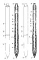
- FIG. 7 is an explanatory view at the time of non-knocking of the writing instrument according to the second embodiment
- FIG. 8 is an explanatory view at the knocking of the writing instrument
- FIG. 9 is an explanatory view of a tip of the writing instrument
- FIG. 11 is an explanatory view around the front axis in the non-writing state
- FIG. 11 is an operation explanatory view during writing when the writing tool is knocked, and is a cross-sectional view taken along the line P-P in FIG.
- the barrel 16 is integrally formed with the main part, and formed by two-color molding of a rubber elastic material and a hard material at the tip of the barrel 16
- a base (tip end member) 42 is provided.
- the grip portion 18 made of a rubber elastic material is formed on the outer periphery of the front end portion of the shaft cylinder 16 with anti-slip unevenness designed on the outer surface.
- the torsion joint 28 and the torsion joint receiver 30 provided in the writing instrument of the first embodiment are not provided in the barrel 16. Therefore, when the writing pressure is applied at the time of writing, the refill 14 is finished but it does not rotate.
- the writing unit 10 of the ballpoint pen tip is provided at the tip of the ink storage unit 12 at the joint 38.
- a clip 44 for fixing the writing tool to a clothes pocket or the like is formed on the side of the inner cylinder 32.
- the base 42 has a hollow and substantially conical shape as a whole, and is provided with a tip portion 42 b made of a rubber elastic material so as to cover the tip of the main body 42 a of the hard resin material.
- the base 42 has a female screw formed in the rear portion of the main body 42 a, and the female screw is screwed to the male screw at the end of the barrel 16.
- the main body 42a has a plurality of valve-like portions extending forward from the formation of the rear internal thread.
- a plurality of ribs 42c are formed so as to project inwards so that the end of the joint 38 of the refill 14 abuts and locks.
- the ribs 42c are preferably arranged at equal intervals at three or more locations.
- the tip portion 42b is disposed at the tip from the part extending in a valve shape from the outer periphery of the internal thread forming portion of the main body 42a to dispose the rubber elastic material. It is formed. It is formed by two-color molding of the tip portion 42b of the elastic material and the main body 42a of the hard material.
- the refill 14 is accommodated in the barrel 16 as shown in FIG. 7 when not writing.
- the writing unit 10 does not protrude outward from the tip.
- the front side (writing portion 10) of the refill 14 is separated from the inner surface of the barrel 16 when not writing.
- the refill 14 When writing is to be performed, the refill 14 is moved forward in the barrel 16 as shown in FIG. 8 by a knock operation on the knock rod 26, and the writing unit 10 protrudes outward from the tip of the mouthpiece 42. become.
- the refill 14 When the writing unit 10 on the front side of the refill 14 does not write, as shown in FIG. 10, the refill 14 is not pressed and does not bend, and the writing unit 10 contacts the tip 42 b of the mouthpiece 42. It is separated from the rib 42c on the inner surface.
- the joint 38 on the rear end side can be moved in a state where the writing portion 10 of the refill 14 abuts on the tip end portion 42b of the mouth ring 42 due to the writing pressure and the writing load. Specifically, since the writing unit 10 has a smaller gap from the opening of the base 42 at the end of the base 42 than the gap between the internal rib 42c and the joint 38, the writing unit 10 contacts the tip of the barrel 16 first. As shown, the joint 38 will reach the rib 42c.
- the refill 14 can be bent at the time of writing to provide a suitable writing feeling.
- the other effects and advantages are the same as in the first embodiment.
- FIG. 12 is an explanatory view of a writing instrument according to a third embodiment of the present invention
- FIG. 13 is an explanatory view of a mouth ring in the writing instrument of FIG.
- the outer shape of the die 46 is substantially the same as that of the die 42 of the second embodiment, but a main body 46a made of a hard resin material is formed over the front and back, and rubber elasticity of a portion from the tip inside the main body 46a
- An annular elastic material 46b such as an O (o) ring made of a material is disposed.
- the rib 46c is formed at the central portion and a female screw at the rear, which is the same as the mouth ring of the second embodiment.
- the refill 14 is accommodated in the barrel 16 as shown in FIGS. 12 (a) and 12 (b) when not writing.
- the front side (writing portion 10) of the refill 14 is separated from the inner surface of the barrel 16 when not writing.
- the refill 14 When writing is to be performed, the refill 14 is moved forward in the barrel 16 as shown in FIGS. It protrudes from the tip to the outside.
- the writing unit 10 in the protruding state has a gap between it and the base 46 tip end opening.
- the joint 38 at the rear end side has a gap with the rib 46 c in a state where a writing pressure is applied and the joint 38 outer periphery of the refill 14 is in contact with the annular elastic member 46 b in the mouthpiece 46 by the writing load. Therefore, the refill 14 is to be done. Specifically, since the gap between the annular elastic member 46 b and the joint 38 is narrower than the gap between the internal rib 46 c and the joint 38 in the base 46, the joint 38 first contacts the base 46 at the tip of the barrel 16, Until 38 hit the rib 46c.
- the refill 14 can be bent at the time of writing to give a suitable writing feeling.
- main body 46a of the die 46 may be integrally formed, and the annular elastic material 46b may be attached to the inside, molding is easy and a standard product is easy to use and cost can be reduced.
- FIG. 14 is an explanatory view of the writing instrument according to the fourth embodiment when not knocking
- FIG. 15 is an explanatory view of knocking the writing instrument
- FIG. 16 is an explanatory view of an inner cylinder of the writing instrument
- FIG. FIG. 18 is an explanatory view of a rotator of the writing instrument
- FIG. 19 is an explanatory view of a torsion joint 52 of the writing instrument.
- the writing instrument according to the fourth embodiment relates to a writing instrument in which a refill 14 in which a writing unit 10 and an ink storage unit 12 are integrally provided is accommodated in a barrel 16 as shown in FIG.
- the refill 14 is similar to that of the first embodiment.
- the front side of the refill 14 is separated from the inner surface of the barrel 16 at the time of unwriting, while it is in contact with the inner surface of the barrel 16 by the writing load at the time of writing.
- the front shaft 48 is inserted into the hollow shaft cylinder 16 from the center first, and the front shaft 48 is engaged by the cylindrical front bearing 48 a screwed inward to the tip of the shaft cylinder 16.
- the base 50 is inserted into the inner periphery of the front bearing 48 a, and the rear end of the base 50 is engaged with the inner periphery of the front shaft 48.
- the rear end of the front shaft 48 is formed flat and is attached to the torsion joint 52 in abutment with the rear end.
- a stepped portion is formed on the inner surface of the tip end portion of the mouth ring 50, and a spring (not shown) is attached to the inside of the shaft cylinder 16 at this stepped portion.
- the refill 14 is biased rearward by the spring.
- the writing unit 10 at the tip of the refill 14 is a ballpoint pen tip, and a knocking pen 58 provided at the rear end of the refill 14 is a writing tool of a knock type ballpoint pen.
- a knock mechanism for advancing and retracting the refill 14 is Unlike the first embodiment, it is of the Cahnnock type.
- the knock mechanism includes a cylindrical rotor 54 in contact with the outer periphery of the ink containing portion 12 within the front shaft 48 on the inner periphery of the shaft cylinder 16 and an inner cylinder 56 externally mounted on the rear end of the rotor 54. Make a cam joint.
- the torsion joint 52 is disposed in contact with the rear end surface of the inner cylinder 56.
- a knocking rod 58 in contact with the rear end of the rotor 54 is disposed in contact with the outer periphery of the ink containing portion 12.
- a torsion joint receiver 60 is disposed in the barrel 16 so as to face the rear end of the torsion joint 52 and fixed to the rear end of the barrel by screwing.
- a knock button 62 protrudes from the rear end of the barrel 16, a knock button 62 is provided at the rear end, and a connecting member 64 connected to the knock rod 58 at the front end is disposed in the torsion joint receiver 60. It is provided to be able to move forward and backward.
- a rotation stop ring 66 is arranged around the connection member 64 to stop the rotation of the knock rod 58.
- the inner cylinder 56 is a substantially cylindrical body in which a cam groove 56 a in which a groove is cut in a long direction and a short direction toward the tip end is formed on the inner circumferential surface.
- the knocking rod 58 is a substantially cylindrical body having a plurality of cam projections 58a formed on the outer periphery at the tip end thereof and projections and depressions of the cam slope 58b formed on the tip surface.
- the rotor 54 is, as shown in FIG. 18, a rough tubular member having projections and depressions on a cam slope 54 a formed on the rear end surface.
- the knock mechanism it is a Kann knock type.
- the rear end of the rotor 54 and the front end of the knock rod 58 are fitted in the inner cylinder 56, and the cams are engaged with each other.
- the knock rod 58 advances with the connection member 64, the position where the cam projection 58a (see FIG. 17) of the knock rod 58 fits in the long and short grooves of the cam groove 56a (see FIG. 16) of the inner cylinder 56 changes.
- the front end of the knock rod 58 changes the pressing position of the rotor 54, and the writing unit 10 of the refill 14 switches from the tip of the front shaft 48 to the non-protruding state / protruding state.
- the torsion joint 52 is made of a rubber elastic material, and a plurality of columnar portions bent in the direction of forming a roughly annular and sloped rear end portion are extended in the backward direction. It is a thing.
- the base 50 is formed longer than the base 46 of the third embodiment and the external appearance shape, but the main body 50a made of a hard resin material is formed over the front and back, and rubber inside of the main body 50a
- An annular elastic member 50b such as an O (o) ring made of an elastic material is disposed (see FIG. 15 (e)).
- the refill 14 is accommodated in the barrel 16 as shown in FIG. 14 when not writing.
- the front side (writing portion 10) of the refill 14 is separated from the inner surface of the barrel 16 when not writing.
- the refill 14 When writing is to be performed, the refill 14 is moved forward in the barrel 16 as shown in FIG. 15 by the knocking operation on the knock button 62, and the writing unit 10 protrudes outside from the end of the mouthpiece 50. It will be in the state.
- the writing unit 10 in the protruding state has a gap between it and the base 50 tip opening.
- the refill 14 is to be done. Specifically, since the gap between the annular elastic material 50b and the joint 38 is narrower than the gap between the inner surface of the mouthpiece 50 and the joint 38 in the mouthpiece 50, the joint 38 first contacts the annular elastic material 50b at the tip of the barrel 16 The joint 38 comes into contact with the inner surface of the base 50.
- the refill 14 can be bent at the time of writing to give a suitable writing feeling.
- the torsion joint 52 is made of a rubber elastic material, and a plurality of columnar portions in the direction in which a slope is formed in a substantially annular shape and a rear end portion is formed.
- the force by which the back end of the torsion joint 52 abuts on the torsion joint receiver 60 is applied by the force that the refill 14 retreats by the writing pressure, and the columnar portion at the rear end of the torsion joint 52 falls or returns
- a force for rotating the refill 14 is generated, and the writing unit 10 is rotated during writing, so that a smooth writing taste can be realized.
- main body 50a of the die 50 may be integrally formed and the annular elastic member 50b may be attached to the inside, molding is easy, and a standard product is easy to use and cost can be reduced.
- FIG. 20 is an explanatory view of a state where the cap is removed from the writing instrument
- FIG. 2 is an explanatory view of a torsion joint of the writing instrument.
- the refill 14 in which the writing section 10 and the ink storage section 12 are integrally provided is accommodated in the shaft cylinder 16, and the cap is attached / removed in a non-knock type.
- the cap is well known and is not shown in FIG.
- the same reference numerals as in the first embodiment denote the same parts as in the first embodiment.
- the front side of the refill 14 is separated from the inner surface of the tip end of the barrel 16 when not writing, and is in contact with the tip inner surface of the barrel 16 by writing load when writing .
- the elastic body 70 is mounted in the base 68 of the tip of the front shaft 20, and the writing unit 10 is in contact with the inner periphery of the hollow barrel 16 at the tip of the refill 14 by the joint 38.
- the elastic body 70 supported on the inner periphery of the front shaft 20 and in contact with the tip of the refill 14 is deformed by a writing load at the time of writing so that the refill 14 bends around the joint 38.
- an external thread is formed on the outer periphery of the front end portion 20 and the rear end of the front end shaft 20, and an external thread on the rear end of the front end shaft 20 is engaged with Join.
- the tapered base 68 covers the tip of the front shaft 20, and the female screw at the rear is engaged with the tip of the front shaft 20.
- the writing unit 10 of the refill 14 is a ballpoint pen tip.
- the joint 38 for connecting the writing unit and the ink storage unit 12 is a hollow shaft-like member (spherical portion 38a) having a spherical central portion, and is tubular
- the rear end of the writing unit 10 is inserted into the front portion of the head, and the cylindrical rear portion is inserted into the tip of the ink container 12 of the refill and integrated with the refill 14.
- the spherical portion 38a of the joint 38 is fixed to the tip of the tip shaft 20 covered with the base 68, the writing unit 10 protrudes from the opening at the tip of the base 68, and
- An elastic body 70 composed of an O (o) ring made of a rubber elastic material mounted on the front of the joint 38 is located around the front end of the joint 38.
- a recess is formed in the spherical side surface at the tip of the front shaft 20, and the rear surface side of the spherical portion 38a of the joint 38 is fitted into the recess, and the front surface is held down by the inner surface of the mouthpiece 68 via the tubular joint retainer 72.
- the joint 38 of the refill 14 is provided rotatably around the center of the joint 38 in the front shaft 20.
- the elastic body 70 with which the front portion of the joint 38 of the refill 14 abuts is deformed by the writing load so that the refill 14 bends around the central portion of the joint 38.
- the refill 14 can be bent at the time of writing, and a suitable writing feeling can be given.
- the outer diameter of the ink containing portion 12 of the main body portion is larger than the outer diameter of the writing portion 10 at the tip end of the refill 14.
- the writing unit 10 at the tip of the refill 14 is a ballpoint pen tip, and is a writing tool of a knock type ballpoint pen provided with a knocking bar 26 at the rear end of the refill 14.
- FIG. 22 to FIG. 22 is an explanatory view at the time of knocking of the writing instrument according to the sixth embodiment
- FIG. 23 is an explanatory view of a tip axis of the writing instrument
- FIG. 24 is an explanatory view of a torsion joint 74 of the writing instrument.
- the writing instrument according to the sixth embodiment is substantially the same as the writing instrument according to the first embodiment except that the structures of the front shaft 20 and the torsion joint 74 are different, and the same reference numerals are given to the same portions.
- a plurality of grooves along the circumferential direction are formed at the tip of the inner main body 20a of the tip shaft 20 of the writing instrument, and the rubber elastic body of the grip 18 is a strip 18a in the circumferential direction.
- a viewing window 18b is formed at the rear of the grip 18 so that the inner main body 20a is exposed. The gripping force at the time of tip gripping is ensured in the band-like portion. Further, by making the inner main body 20a transparent with the viewing window 18b, the remaining amount of ink in the ink storage portion 12 of the refill 14 can be easily visually recognized.
- the torsion joint 74 is formed with two twisting portions. That is, as shown in FIG. 24, at the rear of the torsion joint 74, the plurality of arms 74a are formed in a slightly spiral shape.
- the arm 74a has a large and small part depending on the location in the cross section, and the strength of the part having a small cross section is low, so it is easy to bend, the bent part can be adjusted by setting the size of the cross section, and the bend shape is also adjusted it can.
- a chevron wall 74d is formed on the front main body side of the torsion joint 74 adjacent to the arm 74a, and the chevron wall 74d has a function of a stopper for restricting the working range of the arm 74a.
- a cylindrical portion 74b is connected to the rear end of the arm portion 74a, and a plurality of columnar portions 74c extend rearward at the rear end of the cylindrical portion 74b, and the rear end of the columnar portion 74c is cut obliquely.
- the torsion joint 74 retracts and hits the tip of the torsion joint receiver 30, and the rotational drive of the torsion joint 74 is performed. As a result, the refill 14 rotates and the tip of the writing unit 10 can obtain a smooth writing feeling.
- the refill 14 is compared with the torsion joint of only one of the arm portion and the columnar portion.
- the rotation direction twist is large, and a large amount of rotation can be obtained with a little writing pressure, and a smooth writing taste can be obtained.
- the other actions are the same as in the first embodiment.
- FIG. 25 is an explanatory view of a torsion joint 76 of a writing instrument according to a seventh embodiment of the present invention.
- the torsion joint 76 is made of a long cylindrical rubber elastic material, and an inclined surface is formed at the rear end of the cylindrical main body, in the direction A plurality of bent columnar portions 76a extend rearward.
- a material thermoplastic elastomer, natural rubber, synthetic rubber, etc. can be used.
- the configuration and operation of the other writing instruments are the same as in the first embodiment and the sixth embodiment.
- FIG. 26 is an explanatory view of a torsion joint of a writing instrument according to an eighth embodiment of the present invention.
- the torsion joint 78 is made of a long cylindrical rubber elastic material, and an inclined surface is formed at the rear end of the cylindrical main body 78b.
- a plurality of columnar portions 78a bent in the direction of bending are extended rearward.
- a plurality of grooves 78c extending in the axial direction are formed on the outer peripheral surface of the main body 78b.
- the torsion joint 78 has the groove 78c on the surface of the main body 78b, the main body 78b is also easy to twist, and the main body 78b is also twisted with the twisting of the columnar portion 78a at the rear end to further improve the writing quality.
- the configuration and operation of the other writing instruments are the same as in the first embodiment, the sixth embodiment, and the seventh embodiment.
- FIG. 27 is an explanatory view of a torsion joint 80 of a writing instrument according to a ninth embodiment of the present invention.
- the torsion joint 80 is formed with a portion to be twisted between the front and rear cylindrical portions. That is, at the rear portion of the torsion joint 80, a plurality of arm portions 80a are formed in a slightly spiral shape, and the cylindrical portion 80b at the rear end is connected by the arm portions 80a.
- the arm 80a is easy to bend because the strength of the small cross section is low because the cross section has large and small parts depending on the location, and the bend can be adjusted by setting the cross section size, and the bend shape is also adjusted it can.
- An angled wall 80c is formed adjacent to the arm 80a, and the angled wall 80c has a function of a stopper for restricting the working range of the arm 80a.
- the rear end surface of the cylindrical portion 80b is formed flat. The configuration and operation of the other writing instruments are the same as in the first embodiment and the sixth embodiment.
- FIG. 28 is an explanatory view of a torsion joint of a writing instrument according to a tenth embodiment of the present invention.
- the torsion joint 82 is formed with a portion to be twisted between the front and rear cylindrical portions. At the rear portion of the torsion joint 82, a plurality of arms 82a are formed in a slightly spiral shape, and a tubular portion 82b at the rear end is connected by the arms 82a.
- the arm 82a is easy to bend because the strength of the small cross section is low because the cross section has large and small parts depending on the location, and the bend can be adjusted by setting the cross section size, and the bend shape is also adjusted it can.
- a rod-like projection 82c is formed on the cylindrical portion 82b of the torsion joint 82 toward the front side and adjacent to the arm 82a, and the rod-like projection 82c has a function of a stopper for restricting the working range of the arm 82a. It is configured.
- the rear end surface of the cylindrical portion 82b is formed flat similarly to the torsion joint 80 in the ninth embodiment shown in FIG.
- the configuration and operation of the other writing instruments are the same as in the first embodiment and the sixth embodiment.
- FIG. 29 is an explanatory view of a torsion joint 84 of a writing instrument according to an eleventh embodiment of the present invention.
- the torsion joint 84 is formed with a portion to be twisted between the front and rear cylindrical portions.
- a plurality of (four in this embodiment) relatively thin arms 84a are formed in a slightly spiral shape at intervals, and the cylindrical parts 84b at the rear end are connected by the arms 84a.
- the arm 84a is easy to bend because the strength of the small cross section is low because the cross section has large and small parts depending on the location, and the bend can be adjusted by setting the cross section size, and the bend shape is also adjusted it can.
- the bar-like protrusion directed to the front side of the tenth embodiment shown in FIG. 28 is not formed.
- the rear end surface of the cylindrical portion 84b is formed flat similarly to the torsion joint 80 in the ninth embodiment shown in FIG.
- the configuration and operation of the other writing instruments are the same as in the first embodiment and the sixth embodiment.
- FIG. 30 is an entire explanatory view of a writing instrument according to a twelfth embodiment, wherein (a) and (b) are explanatory views when knocking (c) and (d) are not knocking.
- FIG. 31 is an explanatory view of a torsion joint of the writing instrument
- FIG. 32 is an explanatory view of a rotational drive unit attached to the torsion joint.
- parts similar to those in the first embodiment are denoted by the same reference numerals.
- the twist joint 86 is provided with a rotation driving portion 88 of another member. That is, as shown in FIG. 31, in the torsion joint 86, the front end of a hollow cylindrical main body made of hard resin material is formed flat, and the rotational drive portion 88 made of a rubber elastic material is formed at the rear end of the main body. It is provided.
- the rotary drive portion 88 is generally tubular as a whole having a length shorter than the outer diameter, and a plurality of column portions are formed in a comb shape protruding rearward from the rear end. The portion has a generally impeller-like shape formed obliquely with respect to the radial direction.
- the rotary drive portion 88 is formed separately and integrated with the main body of the formed torsion joint 86 by fitting, bonding or the like.
- the refill 14 is accommodated in the barrel 16 as shown in FIGS. 30 (c) and 30 (d) when not writing.
- the writing unit 10 does not protrude outward from the tip.
- the refill 14 is moved forward in the barrel 16 as shown in FIGS. 30 (a) and 30 (b) by a knocking operation on the knock bar 26, and the writing unit 10 is It protrudes from the outside.
- FIGS. 33 to 34 are views for explaining that the stick-slip can be reduced by the refill 14 (see FIG. 1) being dead or being rotated.
- the inventor uses the refill 14 to tilt the writing unit 10 as shown in FIG. We examined whether it could be possible to obtain the effect of stick-slip by methods other than bending and bending as well.
- the respective torsional joints shown in the form to the twelfth embodiment are configured.
- FIG. 35 shows stick-slip evaluation of the reduction effect.
- FIG. 36 is a diagram of each locus written on a sheet on which artificial sebum has been applied (the application portion is indicated by a broken line with reference R) by the writing instrument of each ballpoint pen using each refill according to the conventional product and the embodiment. And its enlarged view.
- FIG. 36 (a) shows the conventional product A in which the writing part does not move
- FIG. 36 (b) shows the operation of FIG. 33 (a) in which the refills of the first to sixth embodiments are bent.
- the conventional product B in which the refill moves forward and backward (d) is the sixth and ninth to twelfth embodiment products, and (e) is the first, fourth and sixth to eighth It is explanatory drawing of each writing locus
- the writing track is interrupted, but the practice of the present invention shown in FIGS. 36 (b), (d) and (e).
- the writing trajectory is not broken in the form. Therefore, it is clearly understood that the configuration of the present invention can provide a beautiful handwriting without breaks and without stick-slip in the writing part of the refill.
- the writing instrument of the present invention is suitable for a writing instrument using a refill of a writing tip of a ballpoint pen, but can be used for a refill of various writing instruments such as a fiber core molding core.
Landscapes
- Mechanical Pencils And Projecting And Retracting Systems Therefor, And Multi-System Writing Instruments (AREA)
Abstract
簡単な構成でリフィルを回転させて所望の書き味が得られる筆記具を提供する。 筆記部とインク収容部とを一体に設けたリフィルを軸筒内に収容した筆記具において、後方への筆記荷重をリフィルに与えた際にリフィルが軸心を中心に回転する筆記具。
Description
本発明は、筆記におけるスティックスリップを抑え、書き味の向上が図れる筆記具に関する。
従来、先端に筆記部のあるリフィルが軸筒に固定された又はノック式のリフィルを設けた筆記具においては、使用者がリフィル先端の筆記部を軸筒から突出させて筆記する際に、リフィルを軸筒に対して定位置にして筆記する。
通常、リフィルを軸筒に固定したものでは、筆記時に固い感触が得られる。固い感触では、長時間の筆記では、疲労する場合がるので、柔らかい筆記感触が要請された。
そのため、リフィルを軸筒に対して軸芯方向に移動可能にした筆記具がある。例えば、筆記荷重による感触の悪さを避けるようにした技術が開示されている。
そのため、リフィルを軸筒に対して軸芯方向に移動可能にした筆記具がある。例えば、筆記荷重による感触の悪さを避けるようにした技術が開示されている。
例えば、筆記具には、ノックボタン先端に緩衝要素を設けてリフィルを押圧し、筆記中に加えられる圧力に応動する筆記具が開示されている(特開2006-520281公報:特許文献1参照)。
また、同様、リフィルを先方に差し込む緩衝デバイス設けて使用者に好ましい感覚を与えるようにしたものが開示されている(特表2009-542466号公報:特許文献2)
上記特許文献の発明では、一般に、紙面に皮脂が乗っている場合にボールペン等の筆記具において、ボールが紙面上で滑ることによって、筆記線が途切れる場合がある。
そこで発明者は、表面における追従性に関する分析を行い、スティックスリップ現象に着目し、(「田中久一郎著、摩擦のおはなし」1985年、財団法人日本規格協会発行:非特許文献1参照)筆記の際にリフィルを径方向に回転させれば、スティックスリップを防止し、筆記線が途切れる現象を防ぐことで書き味が良くなることを発見した。
ところで、国際公開2007/142135号(:特許文献3)では、芯を回転させるシャープペンシルが開示されている。
このシャープペンシルでは、摩耗による筆記軌跡が太くなったり、細くなったり、線幅が不安定になることを防止するために、一定荷重下において芯を回転させるものであるが、構造が比較的複雑である。また、筆記荷重に応じて芯の回転量を変化させられる構造ではなく、これをボールペン等に利用しても紙面に皮脂が乗ったときに筆記線が途切れることを防止できる技術ではない。
そのため、従来の筆記具ではスティックスリップを効果的に防止することを採用する技術がなかったものである。
「田中久一郎著、摩擦のおはなし」1985年、財団法人日本規格協会発行
本発明は、斯かる実情に鑑み、簡単な構成でリフィルを回転させて所望の書き味が得られる筆記具を提供しようとするものである。
本発明は、筆記部とインク収容部とを一体に設けたリフィルを軸筒内に収容した筆記具において、
後方への筆記荷重をリフィルに与えた際にリフィルが軸心を中心に回転することを特徴とする筆記具である。
後方への筆記荷重をリフィルに与えた際にリフィルが軸心を中心に回転することを特徴とする筆記具である。
本発明において、リフィル又は軸筒内には、筆記荷重によってリフィルを軸心中心に回転させるための、捩じり部材が配置されていることが好適である。
本発明において、リフィル軸心を中心に回転させるための捩じり部材が、リフィルに装着されていることが好適である。
本発明において、筆記荷重が3Nにおけるリフィルの回転する角度が1度以上であることが好適である。
本発明において、リフィルを前後に摺動可能なノック式ボールペンである。
本発明において、捩じり部材は、リフィルに装着される概略筒状の本体と、該本体の軸方向の何れかまたは両側の端部に複数の柱状部とからなり、複数の柱状部は、前記リフィルの軸心を中心にした周方向に傾斜して形成すると共に、
前記捩じり部材は、筆圧により柱状部が傾斜方向に倒れてリフィルと軸筒とが相対回転するようにしたことが好適である。
前記捩じり部材は、筆圧により柱状部が傾斜方向に倒れてリフィルと軸筒とが相対回転するようにしたことが好適である。
本発明において、捩じり部材は、リフィルに装着される概略筒状の本体と、該本体の軸方向に連続した弾性圧縮部分とで形成され、
前記弾性圧縮部分は、外径の一部には溝又は穴が形成された部分であり、
前記捩じり部材は、筆記荷重によって弾性圧縮部分が変形してリフィルと軸筒とを相対回転させるようにしたことが好適である。
前記弾性圧縮部分は、外径の一部には溝又は穴が形成された部分であり、
前記捩じり部材は、筆記荷重によって弾性圧縮部分が変形してリフィルと軸筒とを相対回転させるようにしたことが好適である。
本発明の筆記具によれば、後方への筆記荷重をリフィルに与えた際にリフィルが軸心を中心に回転するものである。筆記時にリフィルが回転することで、スティックスリップ性を抑えて良好な描線を得ることができると共に好適な筆記感を与えることができるという優れた効果を奏し得る。
以下、本発明の実施形態について添付図面を参照して説明する。
(第1実施形態)
まず、本発明の第1実施形態に係る筆記具について図1~図6を参照して説明する。
まず、本発明の第1実施形態に係る筆記具について図1~図6を参照して説明する。
図1は筆記具の非ノック時の説明図、図2はノック時の説明図、図3が該筆記具の先軸の説明図、図4が該筆記具の捩じり継手の説明図、図5が該筆記具のノック時の非筆記状態における先軸周辺の説明図、図6が該筆記具の筆記状態における先軸周辺の作動説明図である。
第1実施形態に係る筆記具は、図1に示すように、筆記部10とインク収容部12とを一体に設けたリフィル14を軸筒16内に収容した筆記具に係るものである。
リフィル14の前方側は、未筆記時においては軸筒16内面と離間し、一方、筆記時は筆記荷重により軸筒16内面と当接するものである。
詳しくは、中空の軸筒16は、中央部から先の先軸20と、中央部から後ろの後軸22とが互いに螺合して着脱自在に連結されたものであり、一体の軸筒16を構成している。
先軸20の先端部内面に段部20bが形成され、この段部20bにスプリング24が係止して先軸20内に装着されている。このスプリング24でリフィル14が後方に向け付勢されている。
リフィル14は、先端の筆記部10の外径よりも本体部のインク収容部12の外径が大きく形成されている。リフィル14の先端の筆記部10はボールペンチップであり、リフィル14の後端にノック棒26が設けられた、ノック式ボールペンの筆記具となっている。
リフィル14のインク収容部12の周囲には、捩じり継手28と、その後部に対向して設けた前面が平坦な捩じり継手受け体30が外装される。
後軸22の後端部内に内筒32が嵌着・固定され、この内筒32内に、捩じり継手受け体30の後端に当接するノック用の回転子34が装着される。
内筒32の先端に軸方向に長・短の切り欠き32aが周方向に配列され形成されている。また、ノック用の回転子34の先端外周に突起34aが外径方向に突出形成される。
捩じり継手受け体30と後軸22との間でそれらに形成されたフランジ突起間にノック用のスプリング36が介装されており、スプリング36によって、回転子34とノック棒26が軸筒16(後軸22)に対して後方に付勢されている。
筆記時に、使用者のノック操作において、ノック棒26への押圧によって回転子34を介してリフィル14が先方に移動すると、押圧解除で回転子34先端外周の突起34aが内筒32の先端切り欠き32aの短いものに嵌って、リフィル14の筆記部10突出状態(筆記時状態)を維持する。
一方、筆記終了時、再度の使用者のノック操作において、ノック棒26への押圧によって、回転子34先端外周の突起34aが、内筒32の先端切り欠き32aの短いものから外れて、回転し、押圧解除で長い先端切り欠きに32aに嵌って、リフィル14の筆記部10が没入出状態(非筆記時状態)を維持する。
各部を詳細に説明する。
(リフィル14)
リフィル14においては、先端の筆記部10は、継手38を介してインク収容部12先端に連結されている。第1実施形態の場合、筆記部10が本体の先端にボール10aを設けたボールペンチップであり、内部のインク流路にボール10aを押す内装スプリング10bが設けられている。
(リフィル14)
リフィル14においては、先端の筆記部10は、継手38を介してインク収容部12先端に連結されている。第1実施形態の場合、筆記部10が本体の先端にボール10aを設けたボールペンチップであり、内部のインク流路にボール10aを押す内装スプリング10bが設けられている。
そして、筆記部10の本体が概略筒状であり、後端が開口して内装スプリングが後方に突出している。
継手38は概略中空筒状であって、内径が軸方向中央部で細径になり、その細径の部分に内装スプリング10b後端が当接・支持される。また、継手38の後端部が段状に拡径して、内筒と外筒からなる二重筒構造となり、後端部の二重筒構造が樹脂管のインク収容部12の先端部に内外に包むように装着されている。
この後端部以外の継手38の外径は、筆記部10よりも大径で、かつ、インク収容部12の外径よりも小径に形成されて、段状に拡径している。スプリング24が継手38に外装されて、スプリング24の先端が上記した先軸20の段部20bに、後端が継手38の段状に拡径した部分に当たり、スプリング24によってリフィル14を後方に付勢している。
(先軸20)
先軸20は、図3に示すように、内部本体20aが硬質樹脂材であり、外周面のゴム弾性材料が覆う把持部18になっている。先軸20の後端部の外周に雄ネジが形成され、後端縁から先方に雄ネジの開始部及び1周分を横切って切り欠き20cが切り込み形成されている。切り欠き20cで後軸22(図1参照)の割れを防止できる。
先軸20は、図3に示すように、内部本体20aが硬質樹脂材であり、外周面のゴム弾性材料が覆う把持部18になっている。先軸20の後端部の外周に雄ネジが形成され、後端縁から先方に雄ネジの開始部及び1周分を横切って切り欠き20cが切り込み形成されている。切り欠き20cで後軸22(図1参照)の割れを防止できる。
また、先軸20においては、図3に詳細に示すように、内部本体20aの先端部が側面に複数の窓が開いている。また、図3、図5に詳細に示すように、把持部18のゴム弾性材料が内部本体20a先端部よりも先に形成され、上記窓から内側に突出している(図5参照)。
ゴム弾性材料の把持部18が内部本体20aの先端部よりも先に形成されているので、この把持部18が先軸20先端を形成し、また、内側に突出しており、図5(b)に示すように、筆記時に、筆記部10外周と先軸20先端内周との隙間が小さく、図5(c)に示すように、未筆記時におけるリフィル14外面と軸筒16(先軸20)内面との間隙が大きく、筆記時に筆記荷重により軸筒16内面に最初に当たる位置よりも後方側を大きくしたものになっている。
また、リフィル14と当接する先軸20内面はゴム弾性材料で形成されている。ゴム弾性材料は、先軸20外面の把持部18に形成されており、先軸20内面にも突出形成されている。
このように、軸筒16における先軸20先端部と途中部にゴム弾性材料が内面向きに形成され、筆記時に筆記荷重によりリフィル14が軸筒16の先端部と途中部でゴム弾性材料に当接するようにしたものである。
このように、この先軸20は、ゴム弾性材料の把持部18と硬質材料からなる内部本体20aとの二色成形で形成されている。二色成形が好適であるが、他に、別成形のものを接着、嵌合等により一体化する製法でも良い。
把持部18のゴム弾性材料は材質が熱可塑性エラストマー、天然ゴム、合成ゴム等の各種材料を好適に使用できる。また、内部本体20aの硬質材料はABS、PC、PBT、PP、PET、PMMA(アクリル樹脂)、COC(環状オレフィン樹脂)等の樹脂材が好適に使用できる。
当接する筆記条件は、荷重3N以上、筆記面に対する筆記部の角度が60度に設定することができる。
(捩じり継手28)
捩じり継手28は、図1、図2に示すように、軸筒16内でリフィル14に外装された中空軸状部材であり、捩じり継手28の先端面がリフィル14の継手38(外筒状部)の後端面に当接する位置に配置されている。捩じり継手28は、図4に示すように、硬質樹脂材製の中空筒状の本体の先端が平坦に形成され、該本体の後端にゴム弾性材料からなる回転駆動部40が設けられている。回転駆動部40は、櫛状に複数の柱部分が後方向きに突出形成されていて、各柱部分が周方向に斜めにカットされている。この回転駆動部40は、別成形して、後に、捩じり継手28の本体に一体化したものである。しかしながら、回転駆動部40の弾性が確保できれば、捩じり継手28の本体と回転駆動部40とを同材質で一体成形しても良い。
捩じり継手28は、図1、図2に示すように、軸筒16内でリフィル14に外装された中空軸状部材であり、捩じり継手28の先端面がリフィル14の継手38(外筒状部)の後端面に当接する位置に配置されている。捩じり継手28は、図4に示すように、硬質樹脂材製の中空筒状の本体の先端が平坦に形成され、該本体の後端にゴム弾性材料からなる回転駆動部40が設けられている。回転駆動部40は、櫛状に複数の柱部分が後方向きに突出形成されていて、各柱部分が周方向に斜めにカットされている。この回転駆動部40は、別成形して、後に、捩じり継手28の本体に一体化したものである。しかしながら、回転駆動部40の弾性が確保できれば、捩じり継手28の本体と回転駆動部40とを同材質で一体成形しても良い。
第1実施形態の筆記具によれば、非筆記時には、図1に示すようにリフィル14が軸筒16内に収まっている。筆記部10が先端から外部に突出していない状態である。リフィル14の前方側(筆記部10)は、未筆記時において軸筒16内面と離間している。
そして、筆記をしようとするときには、ノック棒26へのノック操作によって、図2に示すようにリフィル14が軸筒16内で先方に移動して、筆記部10が先端から外部に突出した状態になる。
リフィル14の前方側の筆記部10は、筆記しないときには図5に示すように、リフィル14が押圧されないので曲がらず、筆記部10と継手38とは軸筒16内面と離間している。
そして、筆記時は、筆圧を加わりその筆記荷重によりリフィル14が軸筒16内面と先端が当接し後端が可動でき、しなるものである。具体的には、筆記部10と軸筒16先端の開口との間隙が軸筒16内部と継手38との間隙よりも狭いので、図6に示すように、筆記部10が先に軸筒16先端に当たり継手38が把持部18の内側ゴム弾性材に当たるまでしなる。したがって、実施形態の筆記具では、筆記時にリフィル14がしなり好適な筆記感を与えることができる。
また、筆記部10に筆圧を加えたときにリフィル14が後方に押圧されると、捩じり継手28が後退し捩じり継手受け体30先端に当たって、捩じり継手28の回転駆動によってリフィル14が回転し筆記部10先端が滑らかな筆記感を得ることができる。
このリフィルの回転による作用効果については後に詳細に説明する。
このリフィルの回転による作用効果については後に詳細に説明する。
(第2実施形態)
次に、第2実施形態に係る筆記具について、図7~図11を参照して説明する。
図7は第2実施形態に係る筆記具の非ノック時の説明図、図8は該筆記具のノック時の説明図、図9は該筆記具の先軸の説明図、図10は該筆記具のノック時の非筆記状態における先軸周辺の説明図、図11は、該の筆記具のノック時における筆記時の作動説明図で、図10(c)のP-P線に沿う横断面図である。
次に、第2実施形態に係る筆記具について、図7~図11を参照して説明する。
図7は第2実施形態に係る筆記具の非ノック時の説明図、図8は該筆記具のノック時の説明図、図9は該筆記具の先軸の説明図、図10は該筆記具のノック時の非筆記状態における先軸周辺の説明図、図11は、該の筆記具のノック時における筆記時の作動説明図で、図10(c)のP-P線に沿う横断面図である。
図7~図11に示す第2実施形態の筆記具では、第1実施形態と同様部分に同様符号を付している。
この第2実施形態に係る筆記具では、図7、図8に示すように、軸筒16は主要部が一体であり、軸筒16先端にゴム弾性材料と硬質材料による二色成形で形成されて口金(先端口部材)42を設けたものである。ゴム弾性材料からなる把持部18は、外面に滑り止めの凹凸がデザインされて、軸筒16の先方部の外周に形成されている。
また、軸筒16内に、第1実施形態の筆記具が備えた捩じり継手28、捩じり継手受け体30が設けられてはいない。したがって、筆記時に筆圧を掛けた際にリフィル14がしなるが回転はしないものである。
なお、リフィル14においては、ボールペンチップの筆記部10が継手38でインク収容部12の先端に設けられている。
また、軸筒16後端に嵌着された内筒32には、衣服ポケット等に筆記具を固定するためのクリップ44が内筒32の側部に形成されている。
(口金42)
口金42について図9によって詳しく説明する。
口金42について図9によって詳しく説明する。
口金42は、全体が中空略円錐形状を呈し、硬質樹脂材の本体42aの先端を覆うようにゴム弾性材料からなる先端部42bが設けられる。
口金42は、本体42aの後部内に雌ネジが形成されていて、この雌ネジが軸筒16先端の雄ネジに螺合する構造になっている。本体42aは、後部の雌ネジの形成部から先方に向けて弁状に延びた部分を複数有している。その弁状の部分内周には、リフィル14の継手38先端が当接して係止するために複数のリブ42cが内向きに突出形成されている。なお、リブ42cは3箇所以上の等間隔に配設していることが好ましい。
口金42において、図9、図10に示すように、先端部42bは、前記本体42aの雌ネジ形成部外周から、弁状に延びた部分の間から先端に位置してゴム弾性材料を配設して形成している。弾性材料の先端部42bと硬質材料による本体42aとの二色成形で形成されている。
第2実施形態の筆記具によれば、非筆記時には、図7に示すようにリフィル14が軸筒16内に収まっている。筆記部10が先端から外部に突出していない状態である。リフィル14の前方側(筆記部10)は、未筆記時において軸筒16内面と離間している。
そして、筆記をしようとするときには、ノック棒26へノック操作によって、図8に示すようにリフィル14が軸筒16内で先方に移動して、筆記部10が口金42先端から外部に突出した状態になる。
リフィル14の前方側の筆記部10は、筆記しないときには図10に示すように、リフィル14が押圧されないので曲がらず、筆記部10は口金42の先端部42bと内接するが、継手38と口金42内面のリブ42cとは離間している。
そして、筆記時は、筆圧が加わりその筆記荷重によりリフィル14の筆記部10が口金42の先端部42bが当接した状態で、後端側の継手38が可動でき、しなるものである。具体的には、筆記部10は口金42先端部42bの開口との間隙が内部のリブ42cと継手38との間隙よりも狭いので、筆記部10が先に軸筒16先端に当たり、図11に示すように、継手38がリブ42cに当たるまでしなる。
したがって、第2実施形態の筆記具では、筆記時にリフィル14がしなり好適な筆記感を与えることができる。
その他の作用効果は第1実施形態と同様である。
その他の作用効果は第1実施形態と同様である。
(第3実施形態)
次に、第3実施形態に係る筆記具について、図12~図13を参照して説明する。
次に、第3実施形態に係る筆記具について、図12~図13を参照して説明する。
図12は本発明の第3実施形態に係る筆記具の説明図、図13は図12の筆記具における口金の説明図である。
図12~図13の第3実施形態の筆記具では、第2実施形態と同様部分に同様符号を付している。
第3実施形態では、口金46が第2実施形態の口金42と外観形状がほぼ同じであるが、硬質樹脂材料からなる本体46aが先後にわたり形成され、本体46a内部に先端よりの箇所のゴム弾性材料からなるO(オー)リング等の環状弾性材46bを配置したものである。リブ46cが中央部に、後方に雌ネジが形成されている点は第2実施形態の口金と同じである。
この第3実施形態の筆記具によれば、非筆記時には、図12(a)、(b)に示すようにリフィル14が軸筒16内に収まっている。リフィル14の前方側(筆記部10)は、未筆記時において軸筒16内面と離間している。
そして、筆記をしようとするときには、ノック棒26へノック操作によって、図12(c)、(d)に示すようにリフィル14が軸筒16内で先方に移動して、筆記部10が口金46先端から外部に突出した状態になる。
突出状態の筆記部10は、口金46先端開口との間に間隙がある。
筆記時は、筆圧が加わりその筆記荷重によりリフィル14の継手38外周が口金46内の環状弾性材46bに当接した状態で、後端側の継手38がリブ46cとの間に間隙を有するので、リフィル14がしなるものである。具体的には、口金46内で環状弾性材46bと継手38との間隙が内部のリブ46cと継手38との間隙よりも狭いので、継手38が先に軸筒16先端の口金46に当たり、継手38がリブ46cに当たるまでしなる。
したがって、第3実施形態の筆記具では、筆記時にリフィル14がしなり好適な筆記感を与えることができる。
また、口金46の本体46aが一体的に形成して、内部に環状弾性材46bを装着すれば良いため、成形か簡単で標準品も使い易くコストダウンが図れる。
(第4実施形態)
次に、第4実施形態に係る筆記具について、図14~図19を参照して説明する。
次に、第4実施形態に係る筆記具について、図14~図19を参照して説明する。
図14は第4実施形態に係る筆記具の非ノック時の説明図、図15は該筆記具のノック時の説明図、図16は該筆記具の内筒の説明図、図17は該筆記具のノック棒の説明図、図18は該筆記具の回転子の説明図、図19は該筆記具の捩じり継手52の説明図である。
図14~図19の第4実施形態の筆記具では、第1実施形態と同様部分に同様符号を付している。
第4実施形態に係る筆記具は、図14に示すように、筆記部10とインク収容部12とを一体に設けたリフィル14を軸筒16内に収容した筆記具に係るものである。リフィル14は第1実施形態のものと同様である。
リフィル14の前方側は、未筆記時においては軸筒16内面と離間し、一方、筆記時は筆記荷重により軸筒16内面と当接するものである。
そして、第4実施形態では、中空の軸筒16内に、中央部から先に先軸48が嵌入し、軸筒16の先端部に内側に螺合した筒状の先軸受け48aによって先軸48が軸筒16内に固定される。先軸受け48a内周に口金50が挿入されて、口金50後端が先軸48内周に螺合している。先軸48の後端は平坦に形成され、その後端に当接して捩じり継手52に装着されている。
口金50の先端部内面に段部が形成され、この段部にスプリング(図示省略)が軸筒16内に装着されている。このスプリングでリフィル14が後方に向け付勢されている。
リフィル14の先端の筆記部10はボールペンチップであり、リフィル14の後端に後記のノック棒58が設けられた、ノック式ボールペンの筆記具となっているが、リフィル14を進退動させるノック機構が第1実施形態と異なり、カーンノック式のものとなっている。
このノック機構は、軸筒16内周の先軸48内でインク収容部12の外周に接した筒状の回転子54と、回転子54の後端部に外装・配設された内筒56がカム接合する。
この内筒56後端面に接して、前記の捩じり継手52が配設される。
この内筒56後端面に接して、前記の捩じり継手52が配設される。
また、回転子54の後端に当接するノック棒58がインク収容部12の外周に接して配置される。
軸筒16内には、捩じり継手52の後端に対向して捩じり継手受け60が、軸筒後端に螺合によって固定して配設される。
軸筒16の後端には、ノックボタン62が突出しており、ノックボタン62を後端に設け、先端に前記ノック棒58が接続された接続部材64が、前記捩じり継手受け60内で進退動可能に設けられている。捩じり継手受け60の内周には、接続部材64の周囲に位置してノック棒58の回転を止める回転止めリング66が配置されている。
ここで、前記内筒56は、図16に示すように、内周面に先端向きに長・短に溝が切り込まれたカム溝56aが形成された概略筒状体である。
前記ノック棒58は、図17に示すように、先端部に外周に複数のカム突起58aが形成され、先端面にカム斜面58bの凹凸が形成された概略筒状体である。
前記回転子54は、図18に示すように、後端面にカム斜面54aの凹凸が形成された概略者筒状体である。
なお、ノック機構においては、カーンノック式である。ノック操作においては、図15に示すように、前記内筒56内に、回転子54後端部と、ノック棒58前端部が嵌り込んで、各カムがかみ合っており、ノックボタン62の操作によって、接続部材64でノック棒58が前進すると、ノック棒58のカム突起58a(図17参照)が内筒56のカム溝56a(図16参照)の長・短の溝に嵌り込む位置が変化することにより、ノック棒58前端が回転子54を押圧位置が変化して、リフィル14の筆記部10が先軸48先端から非突出状態・突出状態に切り替わる。
前記捩じり継手52は、図19に示すように、ゴム弾性材料からなり、概略環状で後端部に斜面が形成された方向に曲がった柱状部が複数、後方向きに延設されているものである。
第4実施形態では、口金50が第3実施形態の口金46と外観形状より長く形成されているが、硬質樹脂材料からなる本体50aが先後にわたり形成され、本体50a内部に先端よりの箇所のゴム弾性材料からなるO(オー)リング等の環状弾性材50bを配置したものである(図15(e)参照)。
この第4実施形態の筆記具によれば、非筆記時には、図14に示すようにリフィル14が軸筒16内に収まっている。リフィル14の前方側(筆記部10)は、未筆記時において軸筒16内面と離間している。
そして、筆記をしようとするときには、ノックボタン62へのノック操作によって、図15に示すようにリフィル14が軸筒16内で先方に移動して、筆記部10が口金50先端から外部に突出した状態になる。
突出状態の筆記部10は、口金50先端開口との間に間隙がある。
突出状態の筆記部10は、口金50先端開口との間に間隙がある。
筆記時は、筆圧が加わりその筆記荷重によりリフィル14の継手38外周が口金50内の環状弾性材50bに当接した状態で、後端側の継手38が口金50内壁面との間に間隙を有するので、リフィル14がしなるものである。具体的には、口金50内で環状弾性材50bと継手38との間隙が口金50内面と継手38との間隙よりも狭いので、継手38が先に軸筒16先端の環状弾性材50bに当たり、継手38が口金50内面に当たるまでしなる。
したがって、第4実施形態の筆記具では、筆記時にリフィル14がしなり好適な筆記感を与えることができる。
また、前記捩じり継手52は、図19に示すように、ゴム弾性材料からなり、概略環状で後端部に斜面が形成された方向の柱状部が複数形成されているものであるので、筆記時に筆圧によってリフィル14が後退する力で捩じり継手52後端が捩じり継手受け60に当接する力が加わり、捩じり継手52の後端部の柱状部が倒れたり復帰したりすることにより、リフィル14が回転する力が発生して、筆記中に筆記部10が回転し、滑らかな書き味が実現できる。
また、口金50の本体50aが一体的に形成して、内部に環状弾性材50bを装着すれば良いため、成形か簡単で標準品も使い易くコストダウンが図れる。
(第5実施形態)
本発明の第5実施形態に係る筆記具について図20~図21を参照して説明する。
本発明の第5実施形態に係る筆記具について図20~図21を参照して説明する。
図20は筆記具からキャップを外した状態の説明図、図2は該筆記具の捩じり継手の説明図である。
第5実施形態に係る筆記具は、図20に示すように、筆記部10とインク収容部12とを一体に設けたリフィル14を軸筒16内に収容し、非ノック式でキャップの着・脱で筆記部先端を覆う・露出する形式の筆記具に係るものである。キャップは周知のものであり、図20では、図視していない。その他、第1実施形態等と同様箇所に同様符号を付している。
第5実施形態に係る筆記具は、リフィル14の前方側は、未筆記時においては軸筒16先端の内面と離間し、一方、筆記時は筆記荷重により軸筒16先端内面と当接するものである。
詳しくは、先軸20の先端の口金68内に弾性体70が装着され、リフィル14の先端部に継手38によって筆記部10が中空の軸筒16先端内周に当接するようにし、継手38が先軸20内周に支持され、筆記時の筆記荷重によってリフィル14先端の当接する弾性体70が変形してリフィル14が前記継手38を中心に曲がるようにしたものである。
詳しくは、図20に示すように、先軸20が先部及び後部が外周に雄ネジが形成され、軸筒16先端内周の雌ネジに先軸20後部の雄ネジが螺合してネジ結合する。また、先軸20先部を覆って先細の口金68が後部の雌ネジが先軸20の先部に螺合する。
リフィル14の筆記部10は、ボールペンチップである。第5実施形態において、筆記部とインク収容部12とを繋ぐ継手38は、図21に示すように、中央部が球状に形成された(球状部38a)中空の軸状部材であり、筒状の先方部内に筆記部10の後端が挿入され、筒状の後方部がリフィルのインク収容部12先端に挿入されてリフィル14に一体化する。
筆記具の組み付け状態では、図20に示すように、口金68で覆う先軸20先端に前記継手38の球状部38aが固定され、筆記部10が口金68先端の開口から突出し、かつ、口金68内に装着されたゴム弾性材料からなるO(オー)リングからなる弾性体70が継手38の先方部の周囲に位置している。先軸20の先端に球状側面に凹所が形成され、当該凹所に前記継手38の球状部38aの後面側が嵌り込み、前面側が筒状の継手押さえ72を介して口金68内面で押さえ付けられている。リフィル14の継手38は、先軸20内で継手38中央部を中心に回動可能に設けられている。
筆記時に、筆記荷重によってリフィル14の継手38の先方部が当接する弾性体70が変形してリフィル14が前記継手38の中央部を中心に曲がるようにしたものである。
曲がる際に弾性体70やインク収容部12の弾性力で、筆記時にリフィル14がしなり好適な筆記感を与えることができる。
リフィル14は、先端の筆記部10の外径よりも本体部のインク収容部12の外径が大きく形成されている。リフィル14の先端の筆記部10はボールペンチップであり、リフィル14の後端にノック棒26が設けられた、ノック式ボールペンの筆記具となっている。
(第6実施形態)
次に、本発明の第6実施形態に係る筆記具について、図22~図24を参照して説明する。
図22は第6実施形態に係る筆記具のノック時の説明図、図23は該筆記具の先軸の説明図、図24は該筆記具の捩じり継手74の説明図である。
次に、本発明の第6実施形態に係る筆記具について、図22~図24を参照して説明する。
図22は第6実施形態に係る筆記具のノック時の説明図、図23は該筆記具の先軸の説明図、図24は該筆記具の捩じり継手74の説明図である。
この第6実施形態に係る筆記具は、先軸20と捩じり継手74の構造が異なる以外は、第1実施形態の筆記具とほぼ同様であり、同様部分に同様符号を付している。
この筆記具の先軸20は、図22、図23に示すように、内部本体20aの先端部に周方向に沿う溝が複数形成されて、把持部18のゴム弾性体が周方向の帯状部18aが形成され、かつ、把持部18の後部に内部本体20aが露出するのぞき窓18bが穿設されたものである。帯状の部分で先端握りの際の把持力が確実化する。また、のぞき窓18bで内部本体20aを透明にすることにより、リフィル14のインク収容部12内のインク残量が容易に視認できる。
捩じり継手74は、ねじれる部分が2箇所形成されている。つまり、図24に示すように、捩じり継手74の後部では複数の腕部74aがややスパイラル状に形成される。腕部74aには、横断面に場所によって大小の部分があり横断面が小さい部分の強度が低いので曲がり易く、横断面の大小の設定で曲がり部分を調整でき、また曲がり形状でも曲がり具合を調整できる。捩じり継手74の先方本体側にこの腕部74aに隣接して山形壁74dが形成され、山形壁74dが腕部74aの作動範囲を規制するストッパーの機能を有する構成になっている。
前記腕部74aの後端に筒状部74bが繋がりその筒状部74b後端部に複数の柱状部74cが後方に延びて、柱状部74cの後端が斜めにカットされている。
筆記時に、筆記部10に筆圧を加えたときにリフィル14が後方に押圧されると、捩じり継手74が後退し捩じり継手受け体30先端に当たって、捩じり継手74の回転駆動によってリフィル14が回転し筆記部10先端が滑らかな筆記感を得ることができる。
特に、捩じり継手74が腕部74aと筒状部74bを介して柱状部74cが回転方向に弾性変形するので、腕部や柱状部の一方のみの捩じり継手に比較してリフィル14の回転方向ねじれが大きく、少しの筆圧で大きな回転量を得て、滑らかな書き味を得ることができる。
その他の作用は第1実施形態と同様である。
その他の作用は第1実施形態と同様である。
(第7実施形態)
次に、本発明の第7実施形態に係る筆記具について図25を参照して説明する。
図25は本発明の第7実施形態に係る筆記具の捩じり継手76の説明図である。
次に、本発明の第7実施形態に係る筆記具について図25を参照して説明する。
図25は本発明の第7実施形態に係る筆記具の捩じり継手76の説明図である。
第7実施形態に係る筆記具は、前記捩じり継手76が、図25に示すように、長い円筒状のゴム弾性材料からなり、筒状の本体の後端部に斜面が形成されて方向に曲がった柱状部76aが複数後方向きに延設されているものである。
材質としては熱可塑性エラストマー、天然ゴム、合成ゴム、等を用いることができる。
その他の筆記具の構成や作用は第1実施形態や第6実施形態と同様である。
材質としては熱可塑性エラストマー、天然ゴム、合成ゴム、等を用いることができる。
その他の筆記具の構成や作用は第1実施形態や第6実施形態と同様である。
(第8実施形態)
次に、本発明の第8実施形態に係る筆記具について図26を参照して説明する。
次に、本発明の第8実施形態に係る筆記具について図26を参照して説明する。
図26は本発明の第8実施形態に係る筆記具の捩じり継手の説明図である。
第8実施形態に係る筆記具は、前記捩じり継手78が、図26に示すように、長い円筒状のゴム弾性材料からなり、筒状の本体78bの後端部に斜面が形成されて捩じり方向に曲がった柱状部78aが複数後方向きに延設されている。そして、本体78bの外周面に軸方向に沿う溝78cが複数条形成されているものである。
この捩じり継手78は本体78bの表面に溝78cがあるので、本体78bも捩じれ易く、後端の柱状部78aの捩じれと共に本体78bも捩じれて、一層、書き味が向上する。
その他の筆記具の構成や作用は第1実施形態や第6実施形態、第7実施形態と同様である。
その他の筆記具の構成や作用は第1実施形態や第6実施形態、第7実施形態と同様である。
(第9実施形態)
次に、本発明の第9実施形態に係る筆記具について図27を参照して説明する。
図27は本発明の第9実施形態に係る筆記具の捩じり継手80の説明図である。
次に、本発明の第9実施形態に係る筆記具について図27を参照して説明する。
図27は本発明の第9実施形態に係る筆記具の捩じり継手80の説明図である。
捩じり継手80は、先後の筒状部間に捩じれる部分が形成されている。
つまり、捩じり継手80の後部では複数の腕部80aがややスパイラル状に形成され、この腕部80aによって後端の筒状部80bが繋がったものである。腕部80aには、横断面に場所によって大小の部分があり横断面が小さい部分の強度が低いので曲がり易く、横断面の大小の設定で曲がり部分を調整でき、また曲がり形状でも曲がり具合を調整できる。腕部80aに隣接して山形壁80cが形成され、この山形壁80cが腕部80aの作動範囲を規制するストッパーの機能を有する構成になっている。筒状部80bの後端面は、図24に示した第6実施形態の捩じり継手と異なり、平坦に形成されている。
その他の筆記具の構成や作用は第1実施形態や第6実施形態と同様である。
つまり、捩じり継手80の後部では複数の腕部80aがややスパイラル状に形成され、この腕部80aによって後端の筒状部80bが繋がったものである。腕部80aには、横断面に場所によって大小の部分があり横断面が小さい部分の強度が低いので曲がり易く、横断面の大小の設定で曲がり部分を調整でき、また曲がり形状でも曲がり具合を調整できる。腕部80aに隣接して山形壁80cが形成され、この山形壁80cが腕部80aの作動範囲を規制するストッパーの機能を有する構成になっている。筒状部80bの後端面は、図24に示した第6実施形態の捩じり継手と異なり、平坦に形成されている。
その他の筆記具の構成や作用は第1実施形態や第6実施形態と同様である。
(第10実施形態)
次に、本発明の第10実施形態に係る筆記具について図28を参照して説明する。
図28は本発明の第10実施形態に係る筆記具の捩じり継手の説明図である。
次に、本発明の第10実施形態に係る筆記具について図28を参照して説明する。
図28は本発明の第10実施形態に係る筆記具の捩じり継手の説明図である。
捩じり継手82は、先後の筒状部間に捩じれる部分が形成されている。
捩じり継手82の後部では複数の腕部82aがややスパイラル状に形成され、この腕部82aによって後端の筒状部82bが繋がったものである。腕部82aには、横断面に場所によって大小の部分があり横断面が小さい部分の強度が低いので曲がり易く、横断面の大小の設定で曲がり部分を調整でき、また曲がり形状でも曲がり具合を調整できる。捩じり継手82の筒状部82bには、先方側向けてかつ腕部82aに隣接して棒状突起82cが形成され、棒状突起82cが腕部82aの作動範囲を規制するストッパーの機能を有する構成になっている。筒状部82bの後端面は、図27に示した第9実施形態に捩じり継手80と同様に、平坦に形成されている。
その他の筆記具の構成や作用は第1実施形態や第6実施形態と同様である。
捩じり継手82の後部では複数の腕部82aがややスパイラル状に形成され、この腕部82aによって後端の筒状部82bが繋がったものである。腕部82aには、横断面に場所によって大小の部分があり横断面が小さい部分の強度が低いので曲がり易く、横断面の大小の設定で曲がり部分を調整でき、また曲がり形状でも曲がり具合を調整できる。捩じり継手82の筒状部82bには、先方側向けてかつ腕部82aに隣接して棒状突起82cが形成され、棒状突起82cが腕部82aの作動範囲を規制するストッパーの機能を有する構成になっている。筒状部82bの後端面は、図27に示した第9実施形態に捩じり継手80と同様に、平坦に形成されている。
その他の筆記具の構成や作用は第1実施形態や第6実施形態と同様である。
(第11実施形態)
次に、本発明の第11実施形態に係る筆記具について図29を参照して説明する。
図29は本発明の第11実施形態に係る筆記具の捩じり継手84の説明図である。
次に、本発明の第11実施形態に係る筆記具について図29を参照して説明する。
図29は本発明の第11実施形態に係る筆記具の捩じり継手84の説明図である。
捩じり継手84は、先後の筒状部間に捩じれる部分が形成されている。
捩じり継手84の後部では間隔を置いて複数(この実施形態では4箇所)の比較的細い腕部84aがややスパイラル状に形成され、この腕部84aによって後端の筒状部84bが繋がったものである。腕部84aには、横断面に場所によって大小の部分があり横断面が小さい部分の強度が低いので曲がり易く、横断面の大小の設定で曲がり部分を調整でき、また曲がり形状でも曲がり具合を調整できる。
捩じり継手84の後部では間隔を置いて複数(この実施形態では4箇所)の比較的細い腕部84aがややスパイラル状に形成され、この腕部84aによって後端の筒状部84bが繋がったものである。腕部84aには、横断面に場所によって大小の部分があり横断面が小さい部分の強度が低いので曲がり易く、横断面の大小の設定で曲がり部分を調整でき、また曲がり形状でも曲がり具合を調整できる。
捩じり継手84の本体と筒状部84bとの間に、図28に示した第10実施形態の先方側向けの棒状突起が形成されていない。
筒状部84bの後端面は、図27に示した第9実施形態に捩じり継手80と同様に、平坦に形成されている。
その他の筆記具の構成や作用は第1実施形態や第6実施形態と同様である。
その他の筆記具の構成や作用は第1実施形態や第6実施形態と同様である。
(第12実施形態)
次に、第12実施形態に係る筆記具について、図30~図32を参照して説明する。
図30は第12実施形態に係る筆記具の全体説明図であって、(a)、(b)がノック時(c)、(d)が非ノック時の説明図である。図31は該筆記具の捩じり継手の説明図、図32が捩じり継手に装着する回転駆動部の説明図である。
図30~図32に示す第12実施形態に係る筆記具では、第1実施形態と同様部分に同様符号を付している。
次に、第12実施形態に係る筆記具について、図30~図32を参照して説明する。
図30は第12実施形態に係る筆記具の全体説明図であって、(a)、(b)がノック時(c)、(d)が非ノック時の説明図である。図31は該筆記具の捩じり継手の説明図、図32が捩じり継手に装着する回転駆動部の説明図である。
図30~図32に示す第12実施形態に係る筆記具では、第1実施形態と同様部分に同様符号を付している。
この第12実施形態に係る筆記具では、図30~図32に示すように捩じり継手86に別部材の回転駆動部88を設けたものである。
つまり、捩じり継手86は、図31に示すように、硬質樹脂材製の中空筒状の本体の先端が平坦に形成され、該本体の後端にゴム弾性材からなる回転駆動部88が設けられている。回転駆動部88は、図32に示すように、全体が外径よりも長さの短い概略管状であり、後端から櫛状に複数の柱部分が後方向きに突出形成されていて、各柱部分が径方向に対して斜めに傾いて形成された概略インペラー状の形状を呈している。この回転駆動部88は、別成形であって、成型した捩じり継手86の本体に嵌着や接着等で一体化したものである。
つまり、捩じり継手86は、図31に示すように、硬質樹脂材製の中空筒状の本体の先端が平坦に形成され、該本体の後端にゴム弾性材からなる回転駆動部88が設けられている。回転駆動部88は、図32に示すように、全体が外径よりも長さの短い概略管状であり、後端から櫛状に複数の柱部分が後方向きに突出形成されていて、各柱部分が径方向に対して斜めに傾いて形成された概略インペラー状の形状を呈している。この回転駆動部88は、別成形であって、成型した捩じり継手86の本体に嵌着や接着等で一体化したものである。
第12実施形態の筆記具によれば、非筆記時には、図30(c)、(d)に示すようにリフィル14が軸筒16内に収まっている。筆記部10が先端から外部に突出していない状態である。
そして、筆記をしようとするときには、ノック棒26へノック操作によって、図30(a)、(b)に示すように、リフィル14が軸筒16内で先方に移動して、筆記部10が先端から外部に突出した状態になる。
そして、筆記をしようとするときには、ノック棒26へノック操作によって、図30(a)、(b)に示すように、リフィル14が軸筒16内で先方に移動して、筆記部10が先端から外部に突出した状態になる。
図30(a)、(b)に示すように、突出した筆記部10に筆圧を加えたときにリフィル14が後方に押圧されると、捩じり継手86が後退し回転駆動部88の後端が平坦な捩じり継手受け体30先端に当たり、該後端の柱状部分が周方向に倒れるように曲がることによって回転駆動部88に回転駆動力が発生する。その回転駆動部88に回転駆動力によって捩じり継手86を介してリフィル14が回転し筆記部10先端が滑らかな筆記感を得ることができる。
その他は第1実施形態と同様の作用効果を奏する。
その他は第1実施形態と同様の作用効果を奏する。
ここで、本発明の原理を説明する。
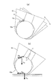
図33~図34は、リフィル14(図1参照)がしなったり、回転したりすることによってスティックスリップが低減できる点を説明する図である。
図33~図34は、リフィル14(図1参照)がしなったり、回転したりすることによってスティックスリップが低減できる点を説明する図である。
スティックスリップに関して、前述の「摩擦のおはなし」(1985年田中久一郎著、財団法人日本規格協会発行))(:非特許文献1)において「第2章 9. スティックスリップ現象(図2.21参照)」に記載があるように、スプリングで支持した物体の滑り摩擦に関し、静摩擦が動摩擦より低い場合、スティックスリップが発生したときは、スティックスリップしないときに比較して摩擦が低減することが考えられる。
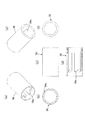
筆記具で考えると、図33の(a)に示すように、ボールペンチップからなる筆記部10先端では、リフィルがしなってペン先が軸の角度が自由に動くことにより、ボール10aと受け座10cとの間で荷重の掛かる点(荷重ポイントP)が移動し、ボール10aが止まらなくなる。インク膜が切れない、また、切れてもインクが荷重の荷重ポイントPに入り込み易くなり、結局、滑らかの筆記感が得られるものである。
スティックスリップ発生時の摩擦力を考える。図33の(b)に示すように、筆記荷重F、筆記荷重Fの垂直成分Fs、ボール受け座10cの受け座摩擦力Ft、紙面の掛かる紙面摩擦力Fpと間で、静止摩擦で、ボール受け座10cのインク潤滑が切れたときに、その受け座摩擦力Ftが上昇する。また、紙面に皮脂が付着したときには紙面摩擦力Fpが減少する。
受け座摩擦力Ft>紙面摩擦力Fpの条件でスティックスリップが発生する。
受け座摩擦力Ft>紙面摩擦力Fpの条件でスティックスリップが発生する。
リフィルの軸方向のみに弾性体で進退動する単純なクッションペンについて考える。
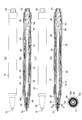
図34に示すように、軸方向へのクッションでボール10aと受け座10cとの位置関係は変わらない。したがって、荷重の集中する点は変化しないため、回転が止まると静止荷重のみがかかりボール10aは動かなくなる。よって、スティックスリップによるスリップ低減効果は生じないと考えられる。
図34に示すように、軸方向へのクッションでボール10aと受け座10cとの位置関係は変わらない。したがって、荷重の集中する点は変化しないため、回転が止まると静止荷重のみがかかりボール10aは動かなくなる。よって、スティックスリップによるスリップ低減効果は生じないと考えられる。
これに対して、発明者は、ボール10aと受け座10cとの間で荷重の係る点とを荷重の方向を変化させるのに、図33に示す様に、筆記部10を傾けるためにリフィル14をしならせて曲げる以外の手法で、同様にスティックスリップの効果を得られるようにできないかを考察した。
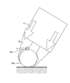
そこで、筆記中に摩擦を変化させるために、リフィルを回転させることを創案したものである。図35に示すように、リフィルの回転によって、荷重ポイントPが回転方向に変化し、スティックスリップ効果を得られると考えたものである。そして、回転運動させるのに、筆記荷重を捩じり運動に変換する構成を、筆圧のオンオフで回転させるのではなく、荷重の変化量と比例するようにリフィルを回転させる機構を創案したものである。
具体的には、上記の図4に示した第1実施形態の捩じり継手28、図19に示した第4実施形態の捩じり継手52、図24~図31に示した第6実施形態~第12実施形態に示した各捩じり継手を構成したものである。
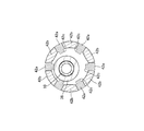
これらの捩じり継手によって図35に示した周方向の荷重ポイントPの移動が軸周りに移動して、スティックスリップ効果が得られたものである。
図36にスティックスリップに低減効果の評価を示す。
図36にスティックスリップに低減効果の評価を示す。
詳しくは、図36は、従来品及び実施形態に係る各リフィルを用いた各ボールペンの筆記具によって、人口皮脂を塗布(塗布部分を符号Rの破線で示す)した紙面上で筆記した各軌跡の図とその拡大図を示すものである。図36の(a)は筆記部が動かない従来品A、(b)は第1実施形態~第6実施形態のリフィルが曲がり前記図33(a)のような動作をするもの、(c)は前記図34(a)のようにリフィルが進退動する従来品B、(d)が第6、第9~第12実施形態品、(e)が第1、第4、第6~第8実施形態品の各筆記軌跡の説明図である。
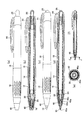
従来品A、従来品Bでは、図36(a)、(c)に示すように、筆記軌跡が途切れているが、図36(b)、(d)、(e)に示す本発明の実施形態に係るものでは、筆記軌跡が途切れていない。したがって、本発明の構成によって、リフィルの筆記部にスティックスリップが発生せず途切れの無い美しい筆跡が得られることが明確に理解される。
本発明の筆記具は、ボールペンの筆記チップのリフィルを用いた筆記具に好適であるが、繊維芯成形芯等の各種筆記具のリフィルに利用することができる。
10 筆記部
10a ボール
10b 内装スプリング
10c ボール受け座
12 インク収容部
14 リフィル
16 軸筒
18 把持部
20 先軸
22 後軸
24 リフィル用のスプリング
26 ノック棒
28 捩じり継手(第1実施形態)
30 捩じり継手受け体
32 内筒
34 回転子
36 ノック機構用のスプリング
38 リフィルの継手
38a 球状部
40 捩じり継手の回転駆動部(第1実施形態)
42 口金(第2実施形態)
46 口金(第3実施形態)
46a 本体
46b 環状弾性材
46c リブ
48 先軸
50 口金(第4実施形態)
50a 本体
50b 環状弾性材
52 捩じり継手(第4実施形態)
68 口金(第5実施形態)
70 弾性体
74 捩じり継手(第6実施形態)
74a 腕部
74b 筒状部
74c 柱状部
74d 山形壁
76 捩じり継手(第7実施形態)
76a 柱状部
78 継手(第8実施形態)
78a 柱状部
78b 本体
78c 外周の溝
80 捩じり継手(第9実施形態)
80a 腕部
80b 筒状部
80c 山形壁
82 捩じり継手(第10実施形態)
82a 腕部
82b 筒状部
82c 棒状突起
84 捩じり継手(第11実施形態)
84a 腕部
84b 筒状部
86 捩じり継手(第12実施形態)
88 回転駆動部
F 筆記荷重
Fp 紙面摩擦力
Fs 垂直成分
Ft 受け座摩擦力
P 荷重ポイント
10a ボール
10b 内装スプリング
10c ボール受け座
12 インク収容部
14 リフィル
16 軸筒
18 把持部
20 先軸
22 後軸
24 リフィル用のスプリング
26 ノック棒
28 捩じり継手(第1実施形態)
30 捩じり継手受け体
32 内筒
34 回転子
36 ノック機構用のスプリング
38 リフィルの継手
38a 球状部
40 捩じり継手の回転駆動部(第1実施形態)
42 口金(第2実施形態)
46 口金(第3実施形態)
46a 本体
46b 環状弾性材
46c リブ
48 先軸
50 口金(第4実施形態)
50a 本体
50b 環状弾性材
52 捩じり継手(第4実施形態)
68 口金(第5実施形態)
70 弾性体
74 捩じり継手(第6実施形態)
74a 腕部
74b 筒状部
74c 柱状部
74d 山形壁
76 捩じり継手(第7実施形態)
76a 柱状部
78 継手(第8実施形態)
78a 柱状部
78b 本体
78c 外周の溝
80 捩じり継手(第9実施形態)
80a 腕部
80b 筒状部
80c 山形壁
82 捩じり継手(第10実施形態)
82a 腕部
82b 筒状部
82c 棒状突起
84 捩じり継手(第11実施形態)
84a 腕部
84b 筒状部
86 捩じり継手(第12実施形態)
88 回転駆動部
F 筆記荷重
Fp 紙面摩擦力
Fs 垂直成分
Ft 受け座摩擦力
P 荷重ポイント
Claims (7)
- 筆記部とインク収容部とを一体に設けたリフィルを軸筒内に収容した筆記具において、
後方への筆記荷重をリフィルに与えた際にリフィルが軸心を中心に回転することを特徴とする筆記具。 - リフィル又は軸筒内には、筆記荷重によってリフィルを軸心中心に回転させるための、捩じり部材が配置されていることを特徴とする請求項1に記載の筆記具。
- リフィル軸心を中心に回転させるための捩じり部材が、リフィルに装着されていることを特徴とする請求項1又は2に記載の筆記具。
- 筆記荷重が3Nにおけるリフィルの回転する角度が1度以上であることを特徴とする請求項1から3のうちのいずれか1項に記載の筆記具。
- リフィルを前後に摺動可能なノック式ボールペンであることを特徴とする請求項1から4のうちのいずれか1項に記載の筆記具。
- 捩じり部材は、リフィルに装着される概略筒状の本体と、該本体の軸方向の何れかまたは両側の端部に複数の柱状部とからなり、複数の柱状部は、前記リフィルの軸心を中心にした周方向に傾斜して形成すると共に、
前記捩じり部材は、筆圧により柱状部が傾斜方向に倒れてリフィルと軸筒とが相対回転するようにしたことを特徴とする請求項2から5のうちのいずれか1項に記載の筆記具。 - 捩じり部材は、リフィルに装着される概略筒状の本体と、該本体の軸方向に連続した弾性圧縮部分とで形成され、
前記弾性圧縮部分は、外径の一部には溝又は穴が形成された部分であり、
前記捩じり部材は、筆記荷重によって弾性圧縮部分が変形してリフィルと軸筒とを相対回転させるようにしたことを特徴とする請求項2から5のうちのいずれか1項に記載の筆記具。
Applications Claiming Priority (4)
| Application Number | Priority Date | Filing Date | Title |
|---|---|---|---|
| JP2013082289A JP6157907B2 (ja) | 2013-04-10 | 2013-04-10 | 筆記具 |
| JP2013-082289 | 2013-04-10 | ||
| JP2013082288A JP6157906B2 (ja) | 2013-04-10 | 2013-04-10 | 筆記具 |
| JP2013-082288 | 2013-04-10 |
Publications (1)
| Publication Number | Publication Date |
|---|---|
| WO2014168196A1 true WO2014168196A1 (ja) | 2014-10-16 |
Family
ID=51689600
Family Applications (1)
| Application Number | Title | Priority Date | Filing Date |
|---|---|---|---|
| PCT/JP2014/060372 Ceased WO2014168196A1 (ja) | 2013-04-10 | 2014-04-10 | 筆記具 |
Country Status (1)
| Country | Link |
|---|---|
| WO (1) | WO2014168196A1 (ja) |
Cited By (1)
| Publication number | Priority date | Publication date | Assignee | Title |
|---|---|---|---|---|
| WO2025089404A1 (ja) * | 2023-10-25 | 2025-05-01 | 三菱鉛筆株式会社 | ノック式筆記具 |
Citations (5)
| Publication number | Priority date | Publication date | Assignee | Title |
|---|---|---|---|---|
| JP2000168289A (ja) * | 1998-12-01 | 2000-06-20 | Masatoshi Iogi | 柔軟性軸ボ―ルペンおよびそれに関連する装置 |
| JP2000335174A (ja) * | 1999-05-31 | 2000-12-05 | Tombow Pencil Co Ltd | 筆記具 |
| JP2001030679A (ja) * | 1999-07-16 | 2001-02-06 | Zebra Pen Corp | 繰出し式筆記具 |
| JP2002160484A (ja) * | 2000-11-22 | 2002-06-04 | Sailor Pen Co Ltd:The | 筆記具 |
| JP2003154787A (ja) * | 2001-11-26 | 2003-05-27 | Sailor Pen Co Ltd:The | 筆記具のレフィール出没機構 |
-
2014
- 2014-04-10 WO PCT/JP2014/060372 patent/WO2014168196A1/ja not_active Ceased
Patent Citations (5)
| Publication number | Priority date | Publication date | Assignee | Title |
|---|---|---|---|---|
| JP2000168289A (ja) * | 1998-12-01 | 2000-06-20 | Masatoshi Iogi | 柔軟性軸ボ―ルペンおよびそれに関連する装置 |
| JP2000335174A (ja) * | 1999-05-31 | 2000-12-05 | Tombow Pencil Co Ltd | 筆記具 |
| JP2001030679A (ja) * | 1999-07-16 | 2001-02-06 | Zebra Pen Corp | 繰出し式筆記具 |
| JP2002160484A (ja) * | 2000-11-22 | 2002-06-04 | Sailor Pen Co Ltd:The | 筆記具 |
| JP2003154787A (ja) * | 2001-11-26 | 2003-05-27 | Sailor Pen Co Ltd:The | 筆記具のレフィール出没機構 |
Cited By (1)
| Publication number | Priority date | Publication date | Assignee | Title |
|---|---|---|---|---|
| WO2025089404A1 (ja) * | 2023-10-25 | 2025-05-01 | 三菱鉛筆株式会社 | ノック式筆記具 |
Similar Documents
| Publication | Publication Date | Title |
|---|---|---|
| JP6422692B2 (ja) | 複数の樹脂成形部材を備えた筆記具または塗布具 | |
| US5988908A (en) | Barrel with finger gripping means | |
| JP6157907B2 (ja) | 筆記具 | |
| JP2011115485A (ja) | 塗布材押出容器 | |
| JP2002331789A (ja) | 筆記具の軸筒 | |
| JP2009039173A (ja) | 塗布材押出容器 | |
| WO2014168196A1 (ja) | 筆記具 | |
| JP6157906B2 (ja) | 筆記具 | |
| JP6159559B2 (ja) | 筆記具 | |
| JP4873730B2 (ja) | 筆記具 | |
| JP6833794B2 (ja) | 出没式多芯筆記具 | |
| JP6242067B2 (ja) | 筆記具 | |
| WO2015087852A1 (ja) | ボールペン | |
| JP5300688B2 (ja) | 筆記具の軸筒 | |
| JP4831696B2 (ja) | 筆記具 | |
| JP4906625B2 (ja) | ノック式筆記具 | |
| JP6291237B2 (ja) | ボールペン | |
| WO2014168195A1 (ja) | 筆記具 | |
| JP5300687B2 (ja) | 筆記具 | |
| JP2681750B2 (ja) | ボ−ルペンの軸筒 | |
| JPH01281999A (ja) | 乾燥防止機構を有するキャップレス筆記具のリフィール機構 | |
| JP2010082892A (ja) | 筆記具 | |
| JP4676905B2 (ja) | 筆記具 | |
| JPH0742793Y2 (ja) | 筆記具のキャップ装着構造 | |
| US3806262A (en) | Dispensing apparatus |
Legal Events
| Date | Code | Title | Description |
|---|---|---|---|
| 121 | Ep: the epo has been informed by wipo that ep was designated in this application |
Ref document number: 14782735 Country of ref document: EP Kind code of ref document: A1 |
|
| NENP | Non-entry into the national phase |
Ref country code: DE |
|
| 122 | Ep: pct application non-entry in european phase |
Ref document number: 14782735 Country of ref document: EP Kind code of ref document: A1 |