WO2014168063A1 - ウェビング巻取装置 - Google Patents
ウェビング巻取装置 Download PDFInfo
- Publication number
- WO2014168063A1 WO2014168063A1 PCT/JP2014/059776 JP2014059776W WO2014168063A1 WO 2014168063 A1 WO2014168063 A1 WO 2014168063A1 JP 2014059776 W JP2014059776 W JP 2014059776W WO 2014168063 A1 WO2014168063 A1 WO 2014168063A1
- Authority
- WO
- WIPO (PCT)
- Prior art keywords
- rotating body
- pull
- lock
- rotation
- out direction
- Prior art date
- Legal status (The legal status is an assumption and is not a legal conclusion. Google has not performed a legal analysis and makes no representation as to the accuracy of the status listed.)
- Ceased
Links
Images












Classifications
-
- B—PERFORMING OPERATIONS; TRANSPORTING
- B60—VEHICLES IN GENERAL
- B60R—VEHICLES, VEHICLE FITTINGS, OR VEHICLE PARTS, NOT OTHERWISE PROVIDED FOR
- B60R22/00—Safety belts or body harnesses in vehicles
- B60R22/34—Belt retractors, e.g. reels
- B60R22/341—Belt retractors, e.g. reels comprising energy-absorbing means
- B60R22/3413—Belt retractors, e.g. reels comprising energy-absorbing means operating between belt reel and retractor frame
-
- B—PERFORMING OPERATIONS; TRANSPORTING
- B60—VEHICLES IN GENERAL
- B60R—VEHICLES, VEHICLE FITTINGS, OR VEHICLE PARTS, NOT OTHERWISE PROVIDED FOR
- B60R22/00—Safety belts or body harnesses in vehicles
- B60R22/28—Safety belts or body harnesses in vehicles incorporating energy-absorbing devices
-
- B—PERFORMING OPERATIONS; TRANSPORTING
- B60—VEHICLES IN GENERAL
- B60R—VEHICLES, VEHICLE FITTINGS, OR VEHICLE PARTS, NOT OTHERWISE PROVIDED FOR
- B60R22/00—Safety belts or body harnesses in vehicles
- B60R22/34—Belt retractors, e.g. reels
- B60R22/36—Belt retractors, e.g. reels self-locking in an emergency
-
- B—PERFORMING OPERATIONS; TRANSPORTING
- B60—VEHICLES IN GENERAL
- B60R—VEHICLES, VEHICLE FITTINGS, OR VEHICLE PARTS, NOT OTHERWISE PROVIDED FOR
- B60R22/00—Safety belts or body harnesses in vehicles
- B60R22/28—Safety belts or body harnesses in vehicles incorporating energy-absorbing devices
- B60R2022/286—Safety belts or body harnesses in vehicles incorporating energy-absorbing devices using deformation of material
- B60R2022/287—Safety belts or body harnesses in vehicles incorporating energy-absorbing devices using deformation of material of torsion rods or tubes
Definitions
- the present invention relates to a webbing take-up device for taking up a webbing of a seat belt device of a vehicle.
- the webbing take-up device disclosed in JP 2012-96745 A includes a force limiter configured to include a main torsion shaft and a sub torsion shaft.
- a force limiter configured to include a main torsion shaft and a sub torsion shaft.
- the force limiter starts to operate, first, the main torsion shaft is twisted and deformed with the rotation of the spool in the pull-out direction, and the sub torsion shaft is rotated together with the spool.
- the spool rotates by a predetermined angle in the pull-out direction from this state, torsional deformation also occurs in the sub torsion shaft.
- the magnitude of the energy absorption load can be switched during the operation of the force limiter.
- this webbing take-up device has a lock ring.
- the lock ring rotates in the pull-out direction together with the sub-torsion shaft in the operating state of the force limiter.
- a lock portion is formed on the lock ring.
- the lock ring since the lock ring is restricted in rotation when the lock portion comes into contact with the switching surface of the body, the lock ring cannot rotate more than one rotation in the pull-out direction. Therefore, the number of rotations in the pulling-out direction of the spool from the start of the torsional deformation of the main torsion shaft to the start of the torsional deformation of the sub torsion shaft is limited to less than one rotation.
- the present invention provides a webbing take-up capable of increasing the number of rotations of the spool from one rotation until the deformation of the second energy absorbing member is started after the deformation of the first energy absorbing member is started. Get the device.
- a webbing take-up device includes a spool for taking up a webbing, a lock base provided so as to be relatively rotatable with respect to the spool on one axial end side of the spool, and the spool being the lock base.
- a first energy absorbing member that is deformed by relative rotation in the pull-out direction, and one end connected to the spool in a state where relative rotation to the spool is restricted, and one end relative to the other end in the pull-out direction
- a second energy absorbing member that is deformed by the rotation, a rotating body that is provided on the other axial end side of the spool and is coaxially rotatable with respect to the spool, and the spool is pulled out with respect to the lock base.
- a connecting means that operates by rotating in a direction to connect the rotating body to the other end of the second energy absorbing member,
- the other end of the second energy absorbing member and the rotating body are integrally rotatable in the pull-out direction, provided on the side of the rotating body, and movable in a direction approaching the rotating body,
- a lock member that restricts rotation of the rotating body in the pull-out direction by approaching the rotating body and engaging with an engaging portion formed on the rotating body, and the locking member engaged with the engaging portion
- a restricting member that restricts the movement of the lock member after the rotation of the rotating body once in the pull-out direction.
- a lock base is provided on one end side in the axial direction of the spool.
- one end of the second energy absorbing member is connected to the spool in a state where relative rotation with respect to the spool is restricted.
- a rotating body is rotatably provided at the other axial end of the spool.
- the webbing take-up device includes a restricting member, and the lock member is restricted from moving to a position where the lock member is engaged with the engaging portion by the restricting member.
- the movement restriction of the lock member by the restriction member is released. For this reason, after the engaging portion has once passed through the side of the lock member, when the engaging portion reaches the side of the lock member again, the lock member engages with the engaging portion, and the rotating body moves in the pull-out direction. Rotation is regulated.
- the second energy absorbing member can be deformed after the spool has rotated more than one rotation with respect to the lock base.
- the webbing take-up device is the webbing retractor according to the first aspect, wherein the engaging portion is an engaging recess opened at an outer peripheral portion of the rotating body, and the rotating member includes the locking member.
- the rotation in the pull-out direction is restricted by entering the engaging recess.
- the restricting member is provided outside the engaging recess so as to be rotatable together with the rotating body and restricts the lock member from entering the engaging recess, and the engaging recess is rotated at the first rotation of the rotating body. After reaching the side of the lock member or passing the side of the lock member, the rotation of the restricting member in the pull-out direction is restricted, and in this state, the rotating body rotates in the pull-out direction.
- the restriction member is configured to release movement restriction on the lock member away from the outside of the engagement recess.
- the engaging portion of the rotating body is an engaging recess opened at the outer peripheral portion of the rotating body.
- the regulating member is provided outside the engaging recess so as to be rotatable together with the rotating body. For this reason, when the rotating member rotates and the engaging concave portion passes the side of the locking member, if the locking member tries to enter the engaging concave portion, the regulating member comes into contact with the locking member. This restricts the lock member from entering the engaging recess.
- the rotating body further rotates in the pull-out direction, thereby the regulating member Is separated from the outside of the engaging recess. For this reason, when the engagement recess reaches the side of the lock member again, the lock member enters the engagement recess, and the rotation of the rotating body in the pull-out direction is restricted by the lock member.
- the webbing take-up device is the webbing take-up device according to the second aspect, wherein the lock member is urged in a direction approaching the outer peripheral portion of the rotating body so as to be in pressure contact with the outer peripheral portion of the rotating body.
- the member is restricted from rotating in the pull-out direction when the lock member is engaged with the restricting member, and enters the engaging recess together with the lock member after the rotating body has made one rotation, thereby restricting movement of the lock member. It is configured to release.
- the lock member is biased toward the outer peripheral portion side of the rotating body, whereby the lock member is pressed against the outer peripheral portion of the rotating body.
- the engagement recess reaches the side of the lock member in the first rotation of the rotating body, the lock member is pressed against a regulating member provided outside the engagement recess.
- the lock member is engaged with the restricting member and restricted from entering the engaging recess.
- the webbing retractor according to a fourth aspect of the present invention is the webbing retractor according to the second aspect, wherein the lock member further includes a support member, and the lock member is a support member that is movable in a direction approaching the outer peripheral portion of the rotating body.
- the regulating member is supported and biased in a direction approaching the outer peripheral portion of the rotating body, and the restricting member is supported by the engaging recess after passing the side of the lock member at the first rotation of the rotating body. It is comprised so that rotation to a drawing-out direction may be controlled in contact with the predetermined part of a member.
- the lock member is supported by the support member so as to be movable in a direction approaching the outer peripheral portion of the rotating body, and further toward the outer peripheral portion side of the rotating body. Be energized. Thereby, the lock member is pressed against the outer peripheral portion of the rotating body. When the engagement recess reaches the side of the lock member in the first rotation of the rotating body, the lock member is pressed against a regulating member provided outside the engagement recess. This restricts the lock member from entering the engaging recess. When the rotating body further rotates in the pulling direction from this state, the restricting member comes into contact with a predetermined portion of the support member. As a result, the restricting member is restricted from rotating in the pull-out direction.
- a webbing retractor is the webbing take-up device according to the first aspect, wherein the engaging portion is an engaging recess opened at an outer peripheral portion of the rotating body, and the rotating member includes the locking member. Rotation in the pull-out direction is restricted by entering the engaging recess, and the lock member is biased in a direction approaching the outer peripheral portion of the rotating body.
- the restricting member is provided outside the engaging recess.
- the engaging recess is engaged after a part of the regulating member is engaged with and pressed by the rotating body at the first rotation of the rotating body, and the engaging recess passes through the side of the lock member. It is comprised so that it may move to the direction away from the outer side of.
- the engaging portion of the rotating body is an engaging recess opened at the outer peripheral portion of the rotating body.
- the lock member is biased in a direction approaching the outer peripheral portion of the rotating body. For this reason, when the lock member moves and enters the engagement recess, the rotation body is restricted from rotating in the pull-out direction by the lock member.
- the regulating member is provided outside the engaging recess, and a part of the regulating member is engaged with the rotating body at the first rotation of the rotating body and is pressed by the rotating body.
- the rotating body rotates in the pull-out direction
- the regulating member is pressed by the rotating body and moves.
- the engaging recess reaches the side of the lock member by rotating the rotating body in the pull-out direction
- the lock member moves in a direction approaching the outer peripheral portion of the rotating body, and the restriction provided outside the engaging recess. Contact the member. For this reason, the lock member cannot enter the engaging recess.
- the webbing retractor is the webbing take-up device according to the first aspect, wherein the engaging portion is an engaging convex portion protruding outward from the outer peripheral portion of the rotating body.
- the rotation in the drawing direction is restricted.
- the regulating member is provided on a rotation locus of the engaging convex portion by the rotation of the rotating body, supports the locking member to regulate the movement of the locking member, and is drawn out at the first rotation of the rotating body. By facing the engaging convex portion of the rotating body rotated in the direction, the engaging convex portion is pressed and displaced to cancel the support of the lock member.
- the lock member is urged in a direction approaching the outer peripheral portion of the rotating body, and the support by the restricting member is released, so that the locking member is pressed against the radially outer surface of the engaging convex portion, and further, the rotating body Is configured so as to approach the outer peripheral portion of the rotating body by rotating in the pull-out direction and to come into contact with the engaging convex portion of the rotating body.
- the engaging part of the rotating body is an engaging convex part protruding from the outer peripheral part of the rotating body to the outside of the rotating body.
- the lock member is biased in a direction approaching the outer peripheral portion of the rotating body, and when the lock member comes into contact with the engaging convex portion from the pulling direction side of the engaging convex portion, the rotating member is pulled in the pulling direction by the locking member. Rotation is regulated.
- the regulating member is provided on the rotation locus of the engaging convex portion by the rotation of the rotating body.
- the lock member is supported by the restricting member, thereby restricting movement of the lock member in a direction approaching the outer peripheral portion of the rotating body.
- the restricting member is pressed by the engaging convex portion and displaced.
- the restricting member is displaced in this way, the movement restriction of the lock member by the restricting member is eliminated.
- the lock member is pressed against the radially outer surface of the engaging projection.
- the webbing retractor according to a seventh aspect of the present invention is the webbing retractor according to the sixth aspect, wherein the webbing retractor further includes a support member, and the restricting member is an elastic piece provided on the support member, and faces the lock member. It is biased to support the lock member and restrict movement.
- the webbing take-up device of the seventh aspect with a simple configuration in which the elastic member is provided on the support member, the lock member is supported by the elastic piece and is restricted from coming into contact with the rotating body, and the rotating body has the elastic piece. By pressing, the elastic piece is deformed to cancel the support of the lock member, and the lock member can come into contact with the rotating body.
- the rotation speed of the spool from the start of the deformation of the first energy absorbing member to the start of the deformation of the second energy absorbing member is more than one rotation. I can do more.
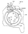
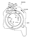
- FIG. 5 is a side view corresponding to FIG. 4 showing a state in which the rotating body is rotated until the engaging recess is positioned on the side of the lock member in the first rotation of the rotating body.
- FIG. 5 is a side view corresponding to FIG. 4 illustrating a state in which the rotating body is rotated in the pull-out direction with respect to the regulating member.
- FIG. 5 is a side view corresponding to FIG. 4 showing a state in which the regulating member and the lock member have entered the engaging recess.
- It is a perspective view which shows the structure of the control member of the webbing retractor which concerns on 2nd Embodiment.
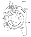
- It is a side view which shows the initial state of the rotary body of a webbing winding device concerning a 2nd embodiment, a lock member, and a regulation member.
- FIG. 10 is a side view corresponding to FIG.
- FIG. 9 illustrating a state in which the rotating body is rotated until the engaging recess is positioned on the side of the lock member in the first rotation of the rotating body.
- FIG. 10 is a side view corresponding to FIG. 9 showing a state in which the rotation of the regulating member in the drawing direction is regulated.
- FIG. 10 is a side view corresponding to FIG. 9 illustrating a state in which the rotating body rotates in the pull-out direction with respect to the regulating member. It is a side view corresponding to FIG. 9 which shows the state which the lock member entered into the engagement recessed part. It is a perspective view which shows the structure of the control member of the webbing retractor which concerns on 3rd Embodiment.
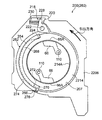
- FIG. 16 is a side view corresponding to FIG. 15 illustrating a state in which the rotating body is rotated until the engaging recess is positioned on the side of the lock member in the first rotation of the rotating body. It is a side view corresponding to FIG. 15 which shows the state which the control member moved. It is a side view corresponding to FIG. 15 which shows the state which the lock member entered into the engagement recessed part. It is a perspective view which shows the structure of the control member of the webbing retractor which concerns on 4th Embodiment.
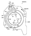
- FIG. 23 is a cross-sectional view corresponding to FIG. 21 in the state of FIG.
- FIG. 22 is a side view corresponding to FIG. 20 illustrating a state in which the rotating body has rotated in the pull-out direction from the state illustrated in FIG. 23.
- FIG. 20 shows the state which the locking member contact
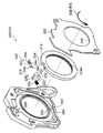
- FIG. 1 is an exploded perspective view showing the configuration of the clutch mechanism 56 in the webbing take-up device 10 according to the first embodiment.
- the webbing take-up device 10 includes a frame 12.
- the frame 12 includes a back plate 28.
- the back plate 28 is formed in a flat plate shape, and leg plates 30 and 32 are extended from one end in the width direction to one side in the thickness direction of the back plate 28.
- the webbing take-up device 10 includes a spool 14.
- the spool 14 has a central axis direction along the opposing direction of the leg plate 30 and the leg plate 32, and most of the spool 14 is located between the leg plate 30 and the leg plate 32.
- the longitudinal direction proximal end side of the long strip webbing 16 is locked to the spool 14.
- the webbing 16 is wound in layers on the outer periphery of the spool 14 from the base end side in the longitudinal direction.
- the webbing 16 wound around the spool 14 is pulled out from the spool 14 while the spool 14 rotates in the pulling direction opposite to the winding direction.
- the spool 14 is formed with a through hole 15 penetrating in the central axis direction. Inside the through hole 15, a main torsion shaft 20 as a first energy absorbing member and a sub torsion shaft 24 as a second energy absorbing member are provided coaxially.
- a force limiter mechanism 26 is configured including the main torsion shaft 20 and the sub torsion shaft 24.
- the main torsion shaft 20 is arranged coaxially with respect to the spool 14 on the inner side of the through hole 15 on the tip side of the middle portion in the longitudinal direction.
- a spline-like spool side engaging portion 42 is formed at the tip of the main torsion shaft 20.
- an engaged portion (not shown) is formed in the inner peripheral portion of the through hole 15 in the center axial direction intermediate portion of the spool 14.
- a lock gear side engaging portion 40 is formed at the longitudinal intermediate portion of the main torsion shaft 20.
- a lock gear 18 serving as a lock base constituting a lock mechanism is provided on the leg plate 32 side of the spool 14 corresponding to the lock gear side engaging portion 40.
- the lock gear 18 is coaxially arranged with respect to the spool 14, and a ratchet gear portion 34 is formed on the outer peripheral portion thereof.
- a through hole 36 penetrating in the central axis direction of the lock gear 18 is formed in the axial center portion of the lock gear 18, and a spline-like engaged portion 38 is formed in the inner peripheral portion of the through hole 36. Yes.
- the lock gear side engaging portion 40 of the main torsion shaft 20 described above is engaged with the engaged portion 38, whereby the lock gear 18 is restricted from rotating relative to the main torsion shaft 20, and further, the spool 14 The relative rotation with respect to is restricted.
- a rod-shaped main energy absorbing portion 44 is formed between the lock gear side engaging portion 40 and the spool side engaging portion 42 of the main torsion shaft 20.
- the lock mechanism of the webbing retractor 10 including the lock gear 18 is provided so that a lock pawl (not shown) can move toward and away from the outer peripheral portion of the lock gear 18 (that is, the ratchet gear portion 34).
- a lock pawl (not shown) can move toward and away from the outer peripheral portion of the lock gear 18 (that is, the ratchet gear portion 34).
- the lock gear 18 is restricted from rotating in the pull-out direction by the lock pawl.
- the spool 14 is restricted from rotating relative to the lock gear 18 via the main torsion shaft 20, the spool 14 is prevented from rotating in the pull-out direction by restricting the lock gear 18 from rotating in the pull-out direction.
- the webbing 16 is pulled out from the spool 14.
- the lock mechanism includes a sensor mechanism that operates when the vehicle suddenly decelerates or when the rotational acceleration in the pull-out direction of the lock gear 18 exceeds a predetermined magnitude. When the sensor mechanism is activated, the lock pawl Moves closer to the outer periphery of the lock gear 18.
- a locking hole 46 is formed on the outer side in the rotational radial direction of the lock gear 18 from the position where the through hole 36 is formed in the lock gear 18.
- the base end portion 22 ⁇ / b> A of the trigger wire 22 is locked in the locking hole 46.
- the distal end side of the trigger wire 22 is inserted into an insertion hole 48 formed in parallel to the through hole 15 in the spool 14. Further, the distal end portion 22 ⁇ / b> B of the trigger wire 22 protrudes outside the spool 14 from the opening end of the insertion hole 48 on the leg plate 30 side.
- the sub torsion shaft 24 is arranged coaxially with respect to the spool 14 on the side of the leg plate 30 with respect to the main torsion shaft 20 in the through hole 15.
- a spline-like spool-side engagement portion 50 is formed at the base end portion of the sub-torsion shaft 24 located on the center side in the central axial direction of the lock gear 18 in the sub-torsion shaft 24.
- the spool side engaging portion 50 is engaged with an engaged portion (not shown) formed on the inner peripheral portion of the through hole 15 on the center side in the central axis direction of the spool 14. As a result, the sub-torsion shaft 24 is restricted from rotating relative to the spool 14. Further, a spline-like sleeve-side engagement portion 52 is formed at a tip portion which is an end portion of the sub torsion shaft 24 on the leg plate 30 side. A portion of the sub torsion shaft 24 between the sleeve side engaging portion 52 and the spool side engaging portion 50 is a sub energy absorbing portion 54.
- a clutch mechanism 56 is provided on the leg plate 30 side of the spool 14.
- the clutch mechanism 56 includes a sleeve 58.
- a through hole 72 is formed in the axial direction of the axial center portion of the sleeve 58.
- a spline-like engaged portion 74 is formed on the distal end side of the inner peripheral portion of the through hole 72 in the sleeve 58.
- the sub torsion shaft 24 is inserted into the through hole 72 from the proximal end side of the sleeve 58, and the sleeve side engaging portion 52 of the sub torsion shaft 24 is engaged with the engaged portion 74. As a result, the sub-torsion shaft 24 is restricted from rotating relative to the sleeve 58.
- the clutch mechanism 56 includes a clutch guide 60.
- a circular through hole 80 is formed in the axial center portion of the clutch guide 60.
- a support portion 76 formed in the sleeve 58 is disposed in the through hole 80 in a state where the support portion 76 passes therethrough.
- the outer diameter of the support portion 76 when viewed in the axial direction of the sleeve 58 is a circle that is substantially the same as the inner diameter size of the through hole 80 (strictly slightly smaller), and the support portion 76 that passes through the through hole 80 is a clutch.
- a guide 60 is rotatably supported. Further, a hole 120 is formed outside the through hole 80 in the clutch guide 60. The hole 120 penetrates the clutch guide 60 in the axial direction.
- the distal end portion 22B of the trigger wire 22 protruding from the insertion hole 48 to the leg plate 30 side passes through the hole portion 120.
- a clutch cover 64 is provided on the side of the clutch guide 60 in the axial direction so as to face the clutch guide 60.
- a through hole 98 is formed in the axial direction of the axial center portion of the clutch cover 64.
- a plurality of fitting claws 100 are formed to protrude radially inward from the inner peripheral portion of the through hole 98. These fitting claws 100 are formed at predetermined angles in the circumferential direction of the through hole 98. These fitting claws 100 are engaged with fitting portions 78 having a substantially hexagonal outer peripheral shape formed on the sleeve 58. As a result, the clutch cover 64 is restricted from displacement in the circumferential direction and the axial direction of the sleeve 58.
- a pair of notches 102 are formed in the clutch cover 64. These notches 102 are formed so as to open outward in the radial direction of the clutch cover 64.
- a cross claw 104 is formed inside each notch 102. These cross claws 104 are bent in a crank shape when viewed in the radial direction of the clutch cover 64, and the distal end protrudes closer to the clutch guide 60 and closer to the winding direction than the proximal end.
- the clutch guide 60 described above corresponding to each coil spring 70 is formed with a coil spring accommodating portion 82, and the coil spring 70 is accommodated therein.
- the coil spring accommodating portion 82 is formed in a concave shape opened toward the drawing direction side, and the bottom portion on the winding direction side is a pressure contact wall 86.
- the other end of the coil spring 70 is in pressure contact with the pressure contact wall 86 by the biasing force.
- the coil spring 70 is compressed by the cross claw 104 and the coil spring accommodating portion 82.
- the clutch guide 60 rotates in the winding direction with respect to the clutch cover 64 by the urging force of the coil spring 70.
- a pair of clutch plates 66 are provided between the clutch guide 60 and the clutch cover 64 as connecting means.
- a clutch plate housing portion 88 is formed in the clutch guide 60 corresponding to the clutch plates 66.
- the clutch plate accommodating portion 88 is formed on the winding direction side of the press contact wall 86 constituting the coil spring accommodating portion 82, and each clutch plate 66 is accommodated inside the clutch plate accommodating portion 88.
- a rotating shaft 110 is formed so as to protrude from the surface of the base end portion of the clutch plate 66 on the clutch cover 64 side.
- a clutch base 62 is provided between the clutch guide 60 and the clutch cover 64.
- the clutch base 62 includes a fitted portion 94 whose inner peripheral shape is hexagonal.
- the inner peripheral shape of the fitted portion 94 is formed substantially equal to the outer peripheral shape of the fitting portion 78 of the sleeve 58 described above, and the fitted portion 94 is fitted into the fitted portion 78. Thereby, the relative rotation of the clutch base 62 with respect to the sleeve 58 is restricted.
- a pair of locking portions 96 are formed on the outer peripheral portion of the fitted portion 94. These locking portions 96 face the clutch plate 66 from the radially inner side of the clutch guide 60.
- the webbing take-up device 10 includes a switching mechanism 200 shown in FIG.
- the switching mechanism 200 includes a sheet member 202.
- a body 206 as a support member is provided on the opposite side of the sheet member 202 from the leg plate 30.
- the body 206 is formed in a concave shape that opens toward the sheet member 202 side.
- the sheet member 202 is fitted and fixed to the body 206 from the opening side of the body 206. Thereby, the opening side of the body 206 is closed by the sheet member 202.
- the inside of the body 206 is a lock ring housing portion 207. Inside the lock ring housing portion 207, a lock ring 214 as a rotating body is provided.
- the lock ring 214 is formed in a ring shape as a whole and is rotatably supported by the body 206. Further, a circular hole 208 is formed in the body 206 so as to penetrate the body 206.
- the inner diameter dimension of the circular hole 208 is set smaller than the outer diameter dimension of the lock ring 214, and is formed coaxially with the lock ring 214.
- a knurled portion 214 ⁇ / b> A is formed on the inner peripheral portion of the lock ring 214.
- a knurled portion 66A is formed on the distal end side of the clutch plate 66 described above.
- the knurled portion 66 ⁇ / b> A meshes with the knurled portion 214 ⁇ / b> A of the lock ring 214.
- the lock ring 214 is restricted from rotating relative to the clutch plate 66.
- a stopper pawl 218 as a lock member is provided on the outer side in the radial direction of the lock ring 214.
- the stopper pawl 218 includes a pawl body 220.
- a hole 222 is formed in the pawl body 220.
- a shaft portion 226 shown in FIG. 4 is formed in the body 206 corresponding to the hole portion 222. As shown in FIGS. 2 and 4, the shaft portion 226 is formed on the sheet member 202 side of the body 206.
- the shaft portion 226 enters the hole 222 of the pawl body 220 and supports the stopper pawl 218 so as to be rotatable around the shaft portion 226.
- an engaging recess 224 as an engaging portion is formed on the outer peripheral portion of the lock ring 214 corresponding to the tip of the stopper pawl 218.
- the stopper pawl 218 is rotated in one engagement direction around the shaft portion 226 in a state where the engagement recess 224 of the lock ring 214 is located on the side of the tip, so that the tip can enter the engagement recess 224.
- the lock ring 214 is restricted from rotating in the pull-out direction.
- an arm piece 228 is extended from the outer peripheral portion of the pawl body 220.
- a compression coil spring 230 is provided on the side of the arm piece 228. One end of the compression coil spring 230 is in pressure contact with the arm piece 228, whereby the stopper pawl 218 is biased in the above-described engagement direction.
- the lock ring 214 is provided with a restriction piece 242 as a restriction member.
- the restriction piece 242 includes a restriction piece main body 244.
- the restriction piece main body 244 is formed in a narrow plate shape whose longitudinal direction is along the rotational contact direction of the lock ring 214.
- a hook-shaped portion 246 extends from one end in the longitudinal direction of the regulating piece main body 244.
- the hook-like portion 246 is bent inward in the radial direction of the lock ring 214 at the middle portion in the longitudinal direction, and the tip thereof is a fitting insertion portion 248.
- a fitting insertion hole 250 is formed on the drawing direction side of the engaging recess 224 formed in the lock ring 214.
- the fitting insertion part 248 of the hook-like part 246 is loosely fitted into the fitting insertion hole 250.
- the restriction piece main body 244 is in contact with the outer peripheral surface of the lock ring 214 at the other end in the longitudinal direction on the winding direction side of the engagement recess 224 in a state in which the insertion portion 248 is fitted in the insertion hole 250. Thereby, the regulation piece main body 244 is located on the opening side of the engaging recess 224 so as to cover the engaging recess 224 from the opening side.
- a notch 252 is formed at the other end in the longitudinal direction of the regulating piece main body 244.
- the notch 252 opens at the other end in the longitudinal direction of the restriction piece main body 244 and penetrates in the thickness direction of the restriction piece main body 244.
- a contact portion 254 is formed on the restriction piece main body 244.
- the contact portion 254 extends from the bottom of the notch 252 to the other end in the longitudinal direction of the restriction piece main body 244.
- the abutting portion 254 has a distal end bent from the intermediate portion in the longitudinal direction outward in the radial direction of the lock ring 214.
- the sensor constituting the lock mechanism when the traveling vehicle suddenly decelerates or the rotational acceleration in the pull-out direction of the spool 14 exceeds a predetermined magnitude, the sensor constituting the lock mechanism is activated. As a result, the lock pawl of the lock mechanism meshes with the ratchet gear portion 34 of the lock gear 18. As a result, the rotation of the lock gear 18 in the pull-out direction is restricted. The lock gear 18 is restricted from rotating relative to the spool 14 via the main torsion shaft 20. For this reason, the rotation of the lock gear 18 in the pull-out direction is restricted, whereby the rotation of the spool 14 in the pull-out direction is restricted.
- the spool 14 tries to rotate in the pull-out direction. If the rotational force of the spool 14 at this time exceeds the mechanical strength of the main energy absorbing portion 44 in the main torsion shaft 20, the spool 14 is pulled out while twisting and deforming the main energy absorbing portion 44 of the main torsion shaft 20. Rotate in the direction.
- the spool 14 can rotate the main energy absorbing portion 44 in the pull-out direction by twisting deformation, and the webbing 16 is pulled out from the spool 14 by a length corresponding to the rotation amount of the spool 14.
- the body of the occupant wearing the webbing 16 can move inertially forward of the vehicle by the length of the webbing 16 drawn from the spool 14. Furthermore, a part of the pulling force applied to the webbing 16 from the occupant's body is subjected to torsional deformation of the main energy absorbing portion 44 and absorbed.
- the trigger wire 22 is pulled toward the base end side.
- the distal end portion 22 ⁇ / b> B of the trigger wire 22 comes out of the hole portion 120 of the clutch guide 60.
- the clutch guide 60 rotates relative to the clutch cover 64 in the winding direction by the biasing force of the coil spring 70 that has been compressed so far.
- the clutch plate 66 rotates around the rotation shaft 110 and the tip of the clutch plate 66 moves outward in the rotational radius direction of the clutch guide 60. Protruding.
- the knurled portion 66 ⁇ / b> A of the clutch plate 66 meshes with the knurled portion 214 ⁇ / b> A of the lock ring 214.
- the lock ring 214 can rotate in the pull-out direction integrally with the clutch cover 64 via the clutch plate 66.
- the clutch cover 64 is connected to the spool 14 through the sleeve 58 and the sub torsion shaft 24 in a state in which relative rotation is restricted. For this reason, when the spool 14 rotates in the pull-out direction as described above, the lock ring 214 rotates in the pull-out direction.
- the lock ring 214 is set so that the tip of the stopper pawl 218 is in pressure contact with the outer peripheral portion of the lock ring 214 on the winding direction side of the engagement recess 224 in the initial state. .
- the rotational force in the pull-out direction exceeds the sum of the mechanical strength of the main energy absorbing portion 44 of the main torsion shaft 20 and the mechanical strength of the sub energy absorbing portion 54 of the sub torsion shaft 24. If so, it can rotate in the pull-out direction As a result, it is possible to absorb a larger amount of energy in the pulling direction than in a state where only the main energy absorbing portion 44 of the main torsion shaft 20 is twisted and deformed.
- the engagement recess 224 is moved once to the side of the tip end of the stopper pawl 218.
- the lock ring 214 is not restricted from rotating in the pull-out direction until the engagement recess 224 reaches the side of the tip of the stopper pawl 218 again after that.
- the rotation speed of the spool 14 required from the start of the torsional deformation of the main torsion shaft 20 to the start of the torsional deformation of the sub torsion shaft 24 exceeds one rotation.
- FIG. 9 shows a configuration of a main part of the webbing take-up device 260 according to the present embodiment by a side view corresponding to FIG. 4 used when explaining the first embodiment.
- the webbing take-up device 260 includes a regulating member 262.
- the regulating member 262 includes a regulating member main body 264.
- the restricting member main body 264 is formed in a narrow plate shape that is curved along the outer periphery of the lock ring 214.
- the restricting member main body 264 is disposed along the outer peripheral portion of the lock ring 214 outside the outer peripheral portion of the lock ring 214.
- a contact piece 266 is formed at the end of the regulating member main body 264 on the drawing direction side. The contact piece 266 extends outward in the radius direction of curvature of the regulating member main body 264.
- a vertical wall 268 is formed at one end in the width direction of the regulating member main body 264. As shown in FIG. 9, the vertical wall 268 extends from the one end in the width direction of the regulating member main body 264 to the inside in the radius of curvature of the regulating member main body 264.
- the vertical wall 268 is located on the side of the surface of the lock ring 214 on the leg plate 30 side in a state where the regulating member main body 264 is disposed along the outer peripheral portion of the lock ring 214.
- a shear pin 270 protrudes from the vertical wall 268 toward the lock ring 214 side.
- the shear pin 270 is fitted in a hole 272 (see FIG. 9) formed in the lock ring 2214.
- the regulating member 262 is connected to the lock ring 2214 and can rotate integrally with the lock ring 2214.
- the restricting member 262 has a portion on the winding direction side of the restricting member main body 264 that covers the engaging recess 224 from the opening side. Thus, it is located on the opening side of the engaging recess 224.
- a contact piece 266 is formed at the end of the regulating member main body 264 on the drawing direction side. The contact piece 266 extends outward in the radius direction of curvature of the regulating member main body 264.
- a fan hole 274 is formed in the body 2206.
- the fan hole portion 274 has a larger radius of curvature than the circular hole 208 (see FIG. 2), and is formed in a fan shape concentric with the circular hole 208.
- the contact piece 266 enters the inside of the fan hole portion 274.
- the contact piece 266 can rotate with the lock ring 2214 inside the fan hole portion 274.
- An end of the fan hole portion 274 on the drawing direction side is a contact portion 276.
- the restricting member 262 is restricted from rotating in the pull-out direction when the contact piece 266 contacts the contact portion 276.
- the regulating member main body 264 has its end on the winding direction side closer to the drawing direction than the tip of the stopper pawl 218 in a state where the contact piece 266 is in contact with the contact portion 276.
- the length in the circumferential direction (longitudinal direction) is set so as to be positioned. For this reason, when the contact piece 266 is in contact with the contact portion 276, only the lock ring 214 rotates in the pull-out direction, and the engagement recess 224 is positioned on the side of the tip of the stopper pawl 218. As shown in FIG. 4, the tip of the stopper pawl 218 can enter the engaging recess 224.
- the engagement recess 224 passes once through the side of the tip of the stopper pawl 218, Thereafter, rotation of the lock ring 2214 in the pull-out direction is not restricted until the engagement recess 224 reaches the side of the tip of the stopper pawl 218 again. Thereby, the rotation speed of the spool 14 required from the start of the torsional deformation of the main torsion shaft 20 to the start of the torsional deformation of the sub torsion shaft 24 exceeds one rotation.
- FIG. 15 shows a configuration of a main part of the webbing take-up device 290 according to the present embodiment by a side view corresponding to FIG. 4 used when explaining the first embodiment.
- the webbing take-up device 290 includes a regulating piece 292 as a regulating member.
- the restricting piece 292 is formed in a narrow plate shape whose longitudinal direction is along the rotational tangent direction of the lock ring 214. As shown in FIG. It is arranged between the tip and the outer periphery of the lock ring 214.
- One end of the restricting piece 292 enters an accommodation hole 294 formed in the body 3206.
- the accommodation hole 294 opens at the inner peripheral portion of the lock ring accommodation portion 207 and can accommodate most of the regulation piece 292.
- a shear wall 296 is formed on the inlet side of the accommodation hole 294, and one end of the regulating piece 292 is in contact with the shear wall 296. As a result, the restriction piece 292 cannot enter the interior of the accommodation hole 294 any more unless the shear wall 296 is broken.
- a notch 298 is formed on the other end side of the regulating piece 292.
- the notch 298 opens at the other end in the longitudinal direction of the restriction piece 292 and penetrates in the thickness direction of the restriction piece 292.
- an elastic contact portion 300 is formed on the restriction piece 292. The elastic contact portion 300 extends from the bottom of the notch 298 in a direction inclined inward in the radial direction of the lock ring 214 with respect to the direction from the other end in the longitudinal direction of the restricting piece 292.
- the elastic contact portion 300 is bent at the middle portion in the longitudinal direction, and the distal end side of the bent portion is closer to the body portion side of the regulating piece 292 with respect to the direction toward the other end side in the longitudinal direction of the regulating piece 292. It extends.
- the restricting piece 292 is interposed between the tip of the stopper pawl 218 and the outer periphery of the lock ring 214. For this reason, even if the tip of the stopper pawl 218 faces the engaging recess 224, the tip of the stopper pawl 218 cannot enter the engaging recess 224.
- the sub-torsion shaft 24 is restricted from rotating in the pull-out direction of the sleeve side engaging portion 52, and the spool 14 rotates in the pull-out direction.
- the torsional deformation is also started in the sub energy absorbing portion 54 of the sub torsion shaft 24.
- the engaging recess 224 passes once through the side of the tip of the stopper pawl 218, Thereafter, the rotation of the lock ring 214 in the pull-out direction is not restricted until the engagement recess 224 reaches the side of the tip of the stopper pawl 218 again. Thereby, the rotation speed of the spool 14 required from the start of the torsional deformation of the main torsion shaft 20 to the start of the torsional deformation of the sub torsion shaft 24 exceeds one rotation.
- FIG. 20 shows a configuration of a main part of the webbing take-up device 320 according to the present embodiment by a side view corresponding to FIG. 4 used when explaining the first embodiment.
- the webbing take-up device 320 includes a lock ring 322 as a rotating body instead of the lock ring 214.
- the engagement recess 224 is not formed in the lock ring 322, and an engagement projection 324 as an engagement portion is formed instead.
- the engaging projection 324 extends radially outward from the outer periphery of the lock ring 322.
- the engaging convex portion 324 has an inclined surface 326 on the winding direction side, and the diameter from the center of the lock ring 322 to the inclined surface 326 is gradually shortened toward the winding direction side on the inclined surface 326.
- the lock ring 322 is restricted from rotating in the pull-out direction by the tip of the stopper pawl 218 coming into contact with the engaging convex portion 324 from the pull-out direction side.
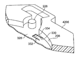
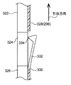
- a rectangular through hole 330 is formed in the bottom wall 328 of the lock ring accommodating portion 207 of the body 4206.
- An elastic piece 332 as a restricting member extends from the end on the winding direction side in the inner peripheral portion of the through hole 330.
- the elastic piece 332 has a narrow plate shape in which the longitudinal direction is the extending direction from the inner peripheral portion of the through hole 330 and the thickness direction is the thickness direction of the bottom wall 328.
- the elastic piece 332 has a free end at its tip, and is elastically deformable about an axis whose axial direction is the width direction, as shown in FIG.
- a support protrusion 334 is formed at the tip of the elastic piece 332.
- the support protrusion 334 is formed so as to protrude from the tip of the elastic piece 332 to the inside of the lock ring housing portion 207.
- the tip end of the stopper pawl 218 is in pressure contact with the upper surface of the support protrusion 334 further on the outer side in the radial direction of the lock ring 322 than the outer surface of the engaging projection 324 of the lock ring 322.
- the support protrusion 334 enters the inside of the lock ring housing portion 207 and is located on the rotation locus of the engagement convex portion 324 due to the rotation of the lock ring 322.
- the support protrusion 334 is pressed by the engaging convex portion 324, and the elastic piece 332 is elastically deformed to the opposite side to the opening side of the lock ring housing portion 207.
- the elastic piece 332 is elastically deformed, the facing state between the upper surface of the support protrusion 334 and the tip of the stopper pawl 218 is canceled.
- the tip of the stopper pawl 218 loses support by the support protrusion 334 and presses against the outer surface of the engaging projection 324.
- the engaging convex portion 324 passes the side of the tip of the stopper pawl 218 once. Thereafter, the rotation of the lock ring 322 in the pull-out direction is not restricted until the tip of the stopper pawl 218 comes into contact with the engagement convex portion 324 from the pull-out direction side. Thereby, the rotation speed of the spool 14 required from the start of the torsional deformation of the main torsion shaft 20 to the start of the torsional deformation of the sub torsion shaft 24 exceeds one rotation.
Landscapes
- Engineering & Computer Science (AREA)
- Mechanical Engineering (AREA)
- Automotive Seat Belt Assembly (AREA)
Abstract
第1エネルギー吸収部材の変形が開始されてから第2エネルギー吸収部材の変形が開始されるまでのスプールの回転数を1回転よりも多くできるウェビング巻取装置を得る。本ウェビング巻取装置10では、係合凹部224の開口側に規制片242が設けられる。このため、ロックリング214の1回転目でストッパパウル218の先端と係合凹部224とが対向しても、ストッパパウル218の先端は、係合凹部224の内側へ入り込むことができない。ストッパパウル218の先端が規制片242の当接部254に当接すると、規制片242の回転が規制される。これによってロックリング214が引出方向に回転すると、規制片242が係合凹部224の開口側から相対移動する。このため、この状態ではストッパパウル218の先端と係合凹部224とが対向すれば、ストッパパウル218の先端は係合凹部224へ入り込むことができる。
Description
本発明は、車両のシートベルト装置のウェビングを巻取るウェビング巻取装置に関する。
特開2012-96745号公報に開示されたウェビング巻取装置は、メイントーションシャフトとサブトーションシャフトを含んで構成されるフォースリミッタを備えている。このウェビング巻取装置では、フォースリミッタが作動開始すると、先ず、スプールの引出方向の回転に伴ってメイントーションシャフトが捩じり変形され、サブトーションシャフトは、その全体がスプールと共に回転する。この状態からスプールが引出方向に所定角度回転すると、サブトーションシャフトにおいても捩じり変形が生じる。
すなわち、このウェビング巻取装置では、フォースリミッタの作動途中でエネルギーの吸収荷重の大きさを切り替えることができる。
ところで、このウェビング巻取装置はロックリングを備えている。ロックリングはフォースリミッタの作動状態でサブトーションシャフトと共に引出方向に回転する。ロックリングにはロック部が形成されており、ロックリングが引出方向に回転して、ロック部がボデーに形成された切替面に当接すると、ロックリングは引出方向への回転が規制される。ロックリングの引出方向への回転が規制されることにより、サブトーションシャフトは先端側で引出方向への回転が規制される。この状態でスプールが引出方向に回転することでサブトーションが捩じり変形される構成である。
このように、ロックリングはロック部がボデーの切替面に当接することで回転規制されるため、ロックリングは1回転を超えて引出方向に回転することができない。したがって、メイントーションシャフトの捩じり変形が開始されてからサブトーションシャフトの捩じり変形が開始されるまでのスプールの引出方向の回転数は1回転未満に限定される。
本発明は、上記事実を考慮して、第1エネルギー吸収部材の変形が開始されてから第2エネルギー吸収部材の変形が開始されるまでのスプールの回転数を1回転よりも多くできるウェビング巻取装置を得る。
本発明の第1態様のウェビング巻取装置は、ウェビングを巻取るスプールと、前記スプールの軸方向一端側で前記スプールに対して相対回転可能に設けられたロックベースと、前記スプールが前記ロックベースに対して引出方向に相対回転することにより変形する第1エネルギー吸収部材と、一端が前記スプールに対する相対回転が規制された状態で前記スプールに繋がり、他端に対して一端が引出方向に相対回転することにより変形する第2エネルギー吸収部材と、前記スプールの軸方向他端側に設けられて、前記スプールに対して同軸的に回転可能な回転体と、前記スプールが前記ロックベースに対して引出方向に回転することにより作動して、前記回転体を前記第2エネルギー吸収部材の他端に連結する連結手段であって、これにより前記第2エネルギー吸収部材の他端と前記回転体とは一体的に引出方向へ回転可能となり、前記回転体の側方に設けられると共に、前記回転体に接近する方向へ移動可能とされ、前記回転体に接近して前記回転体に形成された係合部に係合することにより前記回転体が引出方向に回転することを規制するロック部材と、前記ロック部材が前記係合部に係合する位置まで移動することを規制すると共に、前記回転体が引出方向に1回転した後に前記ロック部材に対する移動規制を解除する規制部材と、を備えている。
第1態様のウェビング巻取装置では、スプールの軸方向一端側にはロックベースが設けられる。ロックベースの引出方向への回転が規制された状態でスプールが引出方向に回転すると、第1エネルギー吸収部材が変形する。これによって、スプールの引出方向への回転力の一部が第1エネルギー吸収部材の変形に供されて吸収される。
また、スプールには第2エネルギー吸収部材の一端がスプールに対する相対回転が規制された状態で繋がっている。また、スプールの軸方向他端側には回転体が回転可能に設けられる。スプールがロックベースに対して引出方向に回転すると、連結手段が作動して、回転体が第2エネルギー吸収部材の他端に間接的に連結される。これによって、回転体は第2エネルギー吸収部材の他端と一体的に引出方向に回転することができる。
この状態で、ロック部材が回転体の係合部に係合すると、回転体の引出方向への回転が規制され、これにより、第2エネルギー吸収部材の他端は引出方向への回転が規制される。このため、この状態でスプールが引出方向に回転すると、スプールの引出方向への回転力の一部は、第1エネルギー吸収部材の変形に供されるのみならず、第2エネルギー吸収部材の変形にも供されて吸収される。
ここで、本発明に係るウェビング巻取装置は規制部材を備えており、ロック部材は規制部材によって係合部に係合する位置まで移動することが規制される。但し、回転体が引出方向に1回転すると、規制部材によるロック部材の移動規制が解除される。このため、係合部がロック部材の側方を一度通過した後に、係合部が再びロック部材の側方に到達すると、ロック部材が係合部に係合し、回転体の引出方向への回転が規制される。
これにより、スプールがロックベースに対して1回転を超えて回転した後に第2エネルギー吸収部材に変形を生じさせることができる。
本発明の第2態様のウェビング巻取装置は、第1態様において、前記係合部は、前記回転体の外周部にて開口した係合凹部とされて、前記回転体は前記ロック部材が前記係合凹部に入り込むことにより引出方向への回転が規制される。前記規制部材は、前記回転体と共に回転可能に前記係合凹部の外側に設けられて前記ロック部材が前記係合凹部に入り込むことを規制し、前記回転体の1回転目で前記係合凹部が前記ロック部材の側方に到達し、又は、前記ロック部材の側方を通過した後に、前記規制部材の引出方向への回転が規制され、この状態で前記回転体が引出方向に回転することにより前記規制部材が前記係合凹部の外側から離れて前記ロック部材に対する移動規制を解除するように構成されている。
第2態様のウェビング巻取装置によれば、回転体の係合部は、回転体の外周部にて開口した係合凹部とされる。ロック部材が回転体の外周部に接近して、係合凹部に入り込むと、ロック部材によって回転体の引出方向への回転が規制される。
一方、規制部材は、回転体と共に回転可能に係合凹部の外側に設けられる。このため、回転体が回転して係合凹部がロック部材の側方を通過する際に、ロック部材が係合凹部に入り込もうとすると、ロック部材に規制部材が当接する。これによって、ロック部材は係合凹部に入り込むことが規制される。
このように、係合凹部が回転体の1回転目でロック部材の側方に到達し、又は、ロック部材の側方を通過した後には、回転体が引出方向に更に回転することによって規制部材が係合凹部の外側から離れる。このため、係合凹部が再びロック部材の側方に到達すると、ロック部材が係合凹部に入り込み、回転体はロック部材によって引出方向への回転が規制される。
本発明の第3態様のウェビング巻取装置は、第2態様において、前記ロック部材は、前記回転体の外周部に接近する方向へ付勢されて前記回転体の外周部に圧接し、前記規制部材は、前記ロック部材が前記規制部材に係合することにより引出方向への回転が規制され、前記回転体が1回転した後に前記ロック部材と共に前記係合凹部に入り込み前記ロック部材に対する移動規制を解除するように構成されている。
第3態様のウェビング巻取装置によれば、ロック部材は回転体の外周部側へ付勢され、これによって、ロック部材は回転体の外周部に圧接される。係合凹部が回転体の1回転目でロック部材の側方に到達すると、ロック部材が係合凹部の外側に設けられた規制部材に圧接される。これによって、ロック部材は規制部材に係合すると共に係合凹部に入り込むことが規制される。
この状態では回転体が引出方向に回転しても、規制部材はロック部材によって引出方向への回転が規制される。このように、回転体が規制部材に対して引出方向に回転することによって、規制部材が係合凹部の外側から離れる。この状態から更に回転体が回転して係合凹部が再びロック部材の側方に到達すると、規制部材がロック部材と共に係合凹部に入り込む。これによって、回転体の引出方向への回転が規制される。
本発明の第4態様のウェビング巻取装置は、第2態様において、更に前記ロック部材は支持部材を備え、前記ロック部材は、前記回転体の外周部に接近する方向へ移動可能に支持部材に支持されると共に前記回転体の外周部に接近する方向へ付勢されて、前記規制部材は、前記回転体の1回転目で前記係合凹部が前記ロック部材の側方を通過した後に前記支持部材の所定部位に当接して引出方向への回転が規制されるように構成されている。
第4態様のウェビング巻取装置によれば、更に支持部材を備え、前記ロック部材は回転体の外周部に接近する方向へ移動可能に支持部材に支持され、更に、回転体の外周部側へ付勢される。これによって、ロック部材は回転体の外周部に圧接される。係合凹部が回転体の1回転目でロック部材の側方に到達すると、ロック部材が係合凹部の外側に設けられた規制部材に圧接される。これによって、ロック部材は係合凹部に入り込むことが規制される。この状態から更に回転体が引出方向に回転すると、規制部材は上記の支持部材の所定部位に当接する。これによって、規制部材は引出方向への回転が規制される。
したがって、この状態で回転体が引出方向に回転することによって、規制部材が係合凹部の外側から離れる。この状態から係合凹部が再びロック部材の側方に到達すると、ロック部材が係合凹部に入り込む。これによって、回転体の引出方向への回転が規制される。
本発明の第5態様のウェビング巻取装置は、第1態様において、前記係合部は、前記回転体の外周部にて開口した係合凹部とされて、前記回転体は前記ロック部材が前記係合凹部に入り込むことにより引出方向への回転が規制され、前記ロック部材は、前記回転体の外周部に接近する方向へ付勢される、前記規制部材は、前記係合凹部の外側に設けられ、前記回転体の一回転目で前記規制部材の一部が前記回転体に係合し前記回転体に押圧され、前記係合凹部が前記ロック部材の側方を通過した後に前記係合凹部の外側から離れる方向へ移動するように構成されている。
第5態様のウェビング巻取装置によれば、回転体の係合部は、回転体の外周部にて開口した係合凹部とされる。ロック部材は回転体の外周部に接近する方向へ付勢されている。このため、ロック部材が移動して係合凹部に入り込むと、回転体はロック部材によって引出方向への回転が規制される。
一方、規制部材は、係合凹部の外側に設けられており、前記回転体の一回転目で前記規制部材の一部は回転体に係合し、前記回転体に押圧され、る。回転体が引出方向に回転すると、規制部材が回転体に押圧されて移動する。回転体が引出方向に回転することで係合凹部がロック部材の側方に到達すると、ロック部材は回転体の外周部へ接近する方向に移動して、係合凹部の外側に設けられた規制部材に当接する。このため、ロック部材は係合凹部に入り込むことができない。
この状態で更に回転体が引出方向に回転すると、規制部材は回転体に押圧されて移動し、これによって、規制部材は係合凹部の外側から離れる。このため、回転体が引出方向に更に回転して係合凹部が再びロック部材の側方に到達すると、ロック部材は係合凹部に入り込む。これによって、回転体の引出方向への回転が規制される。
本発明の第6態様のウェビング巻取装置は、第1態様において、前記係合部は、前記回転体の外周部から前記回転体の外側へ突出した係合凸部とされて、前記回転体は前記ロック部材が引出方向側から前記係合凸部に当接することにより引出方向への回転が規制される。前記規制部材は、前記回転体の回転による前記係合凸部の回転軌跡上に設けられ、前記ロック部材を支持して前記ロック部材の移動を規制すると共に、前記回転体の一回転目で引出方向に回転した前記回転体の係合凸部と対向することにより前記係合凸部に押圧されて変位して前記ロック部材の支持を解消する。、前記ロック部材は、前記回転体の外周部に接近する方向へ付勢され、前記規制部材による支持が解消されることで前記係合凸部の半径方向外側面に圧接し、更に前記回転体が引出方向に回転することにより前記回転体の外周部に接近し、前記回転体の係合凸部と当接可能となるように構成されている。
第6態様のウェビング巻取装置によれば、回転体の係合部は、回転体の外周部から回転体の外側へ突出した係合凸部とされる。ロック部材は、回転体の外周部に接近する方向へ付勢されており、ロック部材が係合凸部の引出方向側から係合凸部に当接すると、回転体はロック部材によって引出方向への回転が規制される。
一方、規制部材は回転体の回転による係合凸部の回転軌跡上に設けられる。ロック部材は、この規制部材によって支持されており、これによって、回転体の外周部へ接近する方向へのロック部材の移動が規制される。回転体が引出方向に回転して、係合凸部が規制部材の側方に到達すると、規制部材が係合凸部に押圧されて変位する。このように規制部材が変位すると、規制部材によるロック部材の移動規制が解消される。これにより、ロック部材は係合凸部の半径方向外側面に圧接される。
この状態で更に回転体が引出方向に回転すると、ロック部材は係合凸部の外側面から離れて回転体の外周面に接近する。この状態で回転体が更に引出方向に回転して係合凸部がロック部材に接近すると、ロック部材は係合凸部に対して引出方向側から当接する。これによって、回転体の引出方向への回転が規制される。
発明の第7態様のウェビング巻取装置は、第6態様において、ウェビング巻き取り装置は更に支持部材を備え、前記規制部材は、前記支持部材に設けられた弾性片であり、前記ロック部材に向かって付勢されて前記ロック部材を支持して移動を規制する。
第7態様のウェビング巻取装置によれば、支持部材に弾性片を設けるという簡易な構成によって、ロック部材を弾性片で支持して回転体に当接することを規制し、回転体が弾性片を押圧することによって弾性片が変形してロック部材の支持を解消して、ロック部材が回転体に当接可能となる。
以上説明したように、本発明に係るウェビング巻取装置は、第1エネルギー吸収部材の変形が開始されてから第2エネルギー吸収部材の変形が開始されるまでのスプールの回転数を1回転よりも多くできる。
次に、本発明の実施の形態について説明する。なお、以下の各実施の形態を説明するに際して、実質的に同一の部位に関しては、同一の符号を付与してその詳細な説明を省略する。
<第1の実施の形態の構成>
図1には第1の実施の形態に係るウェビング巻取装置10におけるクラッチ機構56の構成が分解斜視図によって示されている。
図1には第1の実施の形態に係るウェビング巻取装置10におけるクラッチ機構56の構成が分解斜視図によって示されている。
この図に示されるように、ウェビング巻取装置10はフレーム12を備えている。フレーム12は背板28を備えている。背板28は平板状に形成されており、その幅方向両端からは脚板30、32が背板28の厚さ方向一方の側へ延出されている。また、ウェビング巻取装置10はスプール14を備えている。スプール14は中心軸線方向が脚板30と脚板32との対向方向に沿っており、その大部分が脚板30と脚板32との間に位置している。
このスプール14には長尺帯状のウェビング16の長手方向基端側が係止されている。スプール14が中心軸線周りの一方である巻取方向に回転すると、ウェビング16がその長手方向基端側からスプール14の外周部に層状に巻取られる。また、ウェビング16がその長手方向先端側へ引っ張られると、スプール14が巻取方向とは反対の引出方向に回転しつつ、スプール14に巻取られているウェビング16がスプール14から引出される。
一方、上記のスプール14には、その中心軸線方向に貫通した貫通孔15が形成されている。この貫通孔15の内側には、第1エネルギー吸収部材としてのメイントーションシャフト20と、第2エネルギー吸収部材としてのサブトーションシャフト24とが同軸上に設けられている。これらのメイントーションシャフト20及びサブトーションシャフト24を含んでフォースリミッタ機構26が構成されている。
メイントーションシャフト20は、その長手方向中間部よりも先端側が貫通孔15の内側でスプール14に対して同軸的に配置されている。メイントーションシャフト20の先端部にはスプライン状のスプール側係合部42が形成されている。このスプール側係合部42に対応して、スプール14の中心軸線方向中間部では被係合部(図示省略)が貫通孔15の内周部に形成されている。このスプール側係合部42が被係合部に係合することにより、メイントーションシャフト20はスプール14に対する相対回転が規制された状態でスプール14に繋がっている。
一方、メイントーションシャフト20の長手方向中間部にはロックギヤ側係合部40が形成されている。このロックギヤ側係合部40に対応してスプール14の脚板32側にはロック機構を構成するロックベースとしてのロックギヤ18が設けられている。ロックギヤ18は、スプール14に対して同軸的に配置されており、その外周部にはラチェットギヤ部34が形成されている。また、ロックギヤ18の軸心部分にはロックギヤ18の中心軸線方向に貫通する貫通孔36が形成されており、この貫通孔36の内周部にはスプライン状の被係合部38が形成されている。
一方、メイントーションシャフト20の長手方向中間部にはロックギヤ側係合部40が形成されている。このロックギヤ側係合部40に対応してスプール14の脚板32側にはロック機構を構成するロックベースとしてのロックギヤ18が設けられている。ロックギヤ18は、スプール14に対して同軸的に配置されており、その外周部にはラチェットギヤ部34が形成されている。また、ロックギヤ18の軸心部分にはロックギヤ18の中心軸線方向に貫通する貫通孔36が形成されており、この貫通孔36の内周部にはスプライン状の被係合部38が形成されている。
上述したメイントーションシャフト20のロックギヤ側係合部40は、この被係合部38に係合しており、これにより、ロックギヤ18はメイントーションシャフト20に対する相対回転が規制され、更には、スプール14に対する相対回転が規制される。メイントーションシャフト20のロックギヤ側係合部40と、スプール側係合部42と、の間は棒状のメインエネルギー吸収部44とされている。スプール14がロックギヤ18に対して引出方向に相対回転すると、メインエネルギー吸収部44が捩じれるように変形する。
このロックギヤ18を含んで構成さるウェビング巻取装置10のロック機構は、図示しないロックパウルがロックギヤ18の外周部(すなわち、ラチェットギヤ部34)に対して接離移動可能に設けられる。このロックパウルがロックギヤ18の外周部に接近してラチェットギヤ部34と噛み合うと、ロックギヤ18はロックパウルによって引出方向への回転が規制される。上記のように、スプール14はメイントーションシャフト20を介してロックギヤ18に対する相対回転が規制されているので、ロックギヤ18の引出方向への回転が規制されることによってスプール14は引出方向への回転が規制され、スプール14からのウェビング16の引出しが規制される。
また、ロック機構は車両が急減速した場合や、ロックギヤ18の引出方向への回転加速度が所定の大きさを超えた場合に作動するセンサ機構を備えており、このセンサ機構が作動すると、ロックパウルがロックギヤ18の外周部に接近移動する。
さらに、ロックギヤ18において貫通孔36の形成位置よりもロックギヤ18の回転半径方向外側には係止孔46が形成されている。この係止孔46にはトリガワイヤ22の基端部22Aが係止されている。このトリガワイヤ22の先端側はスプール14において貫通孔15に対して平行に形成された挿通孔48に挿入されている。さらに、トリガワイヤ22の先端部22Bは、挿通孔48の脚板30側の開口端からスプール14の外側へ突出している。
一方、上記のサブトーションシャフト24は、貫通孔15内におけるメイントーションシャフト20よりも脚板30側でスプール14に対して同軸的に配置されている。サブトーションシャフト24においてロックギヤ18の中心軸線方向中央側に位置するサブトーションシャフト24の基端部にはスプライン状のスプール側係合部50が形成されている。
このスプール側係合部50はスプール14の中心軸線方向中央側で貫通孔15の内周部に形成された図示しない被係合部に係合されている。これによって、サブトーションシャフト24はスプール14に対する相対回転が規制されている。また、サブトーションシャフト24の脚板30側の端部である先端部にはスプライン状のスリーブ側係合部52が形成されている。そして、サブトーションシャフト24におけるスリーブ側係合部52とスプール側係合部50との間の部分はサブエネルギー吸収部54とされている。
また、スプール14の脚板30側にはクラッチ機構56が設けられている。クラッチ機構56はスリーブ58を備えている。スリーブ58の軸心部には、軸方向に貫通孔72が形成されている。また、スリーブ58における貫通孔72の内周部の先端側には、スプライン状の被係合部74が形成されている。サブトーションシャフト24は、スリーブ58の基端側から貫通孔72に挿入され、サブトーションシャフト24のスリーブ側係合部52が被係合部74に係合されている。これによって、サブトーションシャフト24はスリーブ58に対する相対回転が規制されている。
また、クラッチ機構56はクラッチガイド60を備えている。クラッチガイド60の軸心部分には円形の貫通孔80が形成されている。この貫通孔80には、スリーブ58に形成された支持部76が貫通した状態で配置されている。支持部76はスリーブ58の軸方向に見て外径寸法が貫通孔80の内径寸法に略等しい(厳密には僅かに小さな)円形とされており、貫通孔80を貫通した支持部76がクラッチガイド60を回転自在に支持している。さらに、クラッチガイド60における貫通孔80の外側には孔部120が形成されている。孔部120はクラッチガイド60の軸方向に貫通している。上述した挿通孔48から脚板30側に突出したトリガワイヤ22の先端部22Bは、この孔部120を貫通している。
このクラッチガイド60の軸方向側方にはクラッチカバー64がクラッチガイド60と対向するように設けられている。このクラッチカバー64の軸心部分には、軸方向に貫通孔98が形成されている。この貫通孔98の内周部からは複数の嵌合爪100が径方向内側に突出形成されている。これらの嵌合爪100は貫通孔98の周方向に所定角度毎に形成されている。これらの嵌合爪100は、スリーブ58に形成された外周形状が略六角形の嵌合部78に係合している。これによって、クラッチカバー64はスリーブ58の周方向及び軸方向への変位が規制されている。
このクラッチカバー64には一対の切欠部102が形成されている。これらの切欠部102は、クラッチカバー64の径方向外側に開口するように形成されている。各々の切欠部102の内側には十字爪104が形成されている。これらの十字爪104は、クラッチカバー64の径方向に見てクランク状に屈曲しており、先端側が基端側よりもクラッチガイド60側で且つ巻取方向側へ突出している。
これらの十字爪104にはコイルスプリング70の一端が係止されている。各コイルスプリング70に対応して上述したクラッチガイド60にはコイルスプリング収容部82が形成されており、コイルスプリング70が収容されている。コイルスプリング収容部82は引出方向側へ向けて開口した凹形状に形成されており、その巻取方向側の底部は圧接壁86とされている。コイルスプリング70は、その付勢力で他端が圧接壁86に圧接している。
トリガワイヤ22が孔部120を貫通した状態では、コイルスプリング70が十字爪104とコイルスプリング収容部82とによって圧縮されている。トリガワイヤ22の先端部22Bが孔部120から抜け出ると、コイルスプリング70の付勢力によってクラッチカバー64に対してクラッチガイド60が巻取方向に回転する。
クラッチガイド60とクラッチカバー64との間には各々が連結手段としての一対のクラッチプレート66が設けられている。これらのクラッチプレート66に対応してクラッチガイド60にはクラッチプレート収容部88が形成されている。クラッチプレート収容部88はコイルスプリング収容部82を構成する圧接壁86の巻取方向側に形成されており、各クラッチプレート66はクラッチプレート収容部88の内側に収容されている。クラッチプレート66の基端部におけるクラッチカバー64側の面からは回動軸110が突出形成されている。
これらの回動軸110は、クラッチカバー64に形成された孔部112に挿し込まれている。これによって、クラッチプレート66はクラッチカバー64に回動可能に支持されている。クラッチガイド60がクラッチカバー64に対して巻取方向に相対回転すると、クラッチカバー64の孔部112にクラッチガイド60の圧接壁86が接近する。これによって、圧接壁86がクラッチプレート66の先端側のクラッチガイド60の中心軸線側を向く面を押圧すると、クラッチプレート66は、その先端側がクラッチガイド60の半径方向外側へ突出するように回動する。
また、クラッチガイド60とクラッチカバー64との間にはクラッチベース62が設けられている。クラッチベース62は、内周形状が六角形状の被嵌合部94を備えている。被嵌合部94の内周形状は、上述したスリーブ58の嵌合部78の外周形状に略等しく形成されており、嵌合部78に被嵌合部94が嵌め込まれている。これにより、クラッチベース62は、スリーブ58に対する相対回転が規制されている。被嵌合部94の外周部には一対の係止部96が形成されている。これらの係止部96はクラッチガイド60の半径方向内側からクラッチプレート66と対向している。
また、本ウェビング巻取装置10は、図2に示される切替機構200を備えている。切替機構200はシート部材202を備えている。シート部材202の脚板30とは反対側には支持部材としてのボデー206が設けられている。ボデー206はシート部材202側へ向けて開口した凹形状に形成されている。シート部材202は、ボデー206の開口側からボデー206に嵌め込まれて固定されている。これにより、ボデー206の開口側がシート部材202によって閉止されている。
ボデー206の内側はロックリング収容部207とされている。ロックリング収容部207の内側には回転体としてのロックリング214が設けられている。ロックリング214は全体的にリング状に形成されており、ボデー206に回転自在に支持されている。さらに、ボデー206には円孔208がボデー206を貫通するように形成されている。円孔208の内径寸法は、ロックリング214の外径寸法よりも小さく設定されており、ロックリング214に対して同軸的に形成されている。
ロックリング214の内周部にはローレット部214Aが形成されている。このローレット部214Aに対応して上述したクラッチプレート66の先端側にはローレット部66Aが形成されている。クラッチプレート66は、先端側がクラッチプレート収容部88の外側へ突出するように回動すると、ローレット部66Aがロックリング214のローレット部214Aと噛み合う。これにより、ロックリング214はクラッチプレート66に対する相対回転が規制される。
上述したように、クラッチプレート66はスリーブ58に対する相対回転が規制されている。このため、クラッチプレート66のローレット部66Aがロックリング214のローレット部214Aと噛み合うことによってロックリング214はスリーブ58に対する相対回転が規制され、ひいては、サブトーションシャフト24のスリーブ側係合部52に対する相対回転が規制される。
ロックリング214の半径方向外側にはロック部材としてのストッパパウル218が設けられている。ストッパパウル218はパウル本体220を備えている。パウル本体220には孔部222が形成されている。この孔部222に対応してボデー206には図4に示される軸部226が形成されている。図2及び図4に示されるように、軸部226はボデー206におけるシート部材202側に形成されている。この軸部226はパウル本体220の孔部222に入り込んでおり、ストッパパウル218を軸部226周りに回動可能に支持している。
また、ストッパパウル218の先端に対応してロックリング214の外周部には係合部としての係合凹部224が形成されている。ストッパパウル218は、その先端の側方にロックリング214の係合凹部224が位置した状態で軸部226周り一方である係合方向へ回動することによって先端が係合凹部224に入り込める。このようにストッパパウル218の先端が係合凹部224の内側に入り込むことによって、ロックリング214は引出方向への回転が規制される。
さらに、パウル本体220の外周部からは腕片228が延出されている。腕片228の側方には圧縮コイルばね230が設けられている。圧縮コイルばね230は、一端が腕片228に圧接しており、これによって、ストッパパウル218は上記の係合方向へ付勢されている。
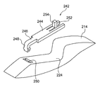
一方、ロックリング214には、規制部材としての規制片242が設けられている。図3に示されるように、規制片242は規制片本体244を備えている。規制片本体244は長手方向がロックリング214の回転接戦方向に沿った細幅板状に形成されている。規制片本体244の長手方向一端からは鉤状部246が延出されている。鉤状部246は、その長手方向中間部でロックリング214の半径方向内側に屈曲されており、その先端は嵌挿部248とされている。
ロックリング214に形成された係合凹部224の引出方向側には嵌挿孔250が形成されている。鉤状部246の嵌挿部248は嵌挿孔250に緩く嵌め込まれている。規制片本体244は、嵌挿部248が嵌挿孔250に嵌め込まれた状態で長手方向他端部が係合凹部224よりも巻取方向側でロックリング214の外周面に当接している。これによって、規制片本体244は係合凹部224をその開口側から蓋をするように係合凹部224の開口側に位置している。このため、係合凹部224がストッパパウル218の先端の側方に位置した状態でストッパパウル218が係合方向に回動すると、ストッパパウル218の先端は規制片本体244に当接する。このため、この状態では、ストッパパウル218の先端は係合凹部224に入り込むことができない。
また、規制片本体244の長手方向他端部には切欠部252が形成されている。切欠部252は規制片本体244の長手方向他端部にて開口していると共に、規制片本体244の厚さ方向に貫通している。さらに、規制片本体244には当接部254が形成されている。当接部254は切欠部252の底部から規制片本体244の長手方向他端側へ延出されている。当接部254は、その長手方向中間部から先端側がロックリング214の半径方向外方へ屈曲されている。
ストッパパウル218の先端が規制片本体244に当接した状態でロックリング214が引出方向に回転すると、ストッパパウル218の先端は当接部254の先端側に当接する。これによって、規制片242は引出方向への移動(回転)が規制される。このため、この状態でロックリング214が更に引出方向に回転すると、図6に示されるように、鉤状部246の嵌挿部248が嵌挿孔250から抜け出る。この状態では、ロックリング214が回転しても規制片242は回転しない。
<第1の実施の形態の作用、効果>
次に、本実施の形態の作用並びに効果について説明する。
次に、本実施の形態の作用並びに効果について説明する。
本ウェビング巻取装置10では、走行中の車両が急減速したり、スプール14の引出方向への回転加速度が所定の大きさを超えたりすると、ロック機構を構成するセンサが作動する。これによって、ロック機構のロックパウルがロックギヤ18のラチェットギヤ部34と噛み合う。これによって、ロックギヤ18の引出方向への回転が規制される。ロックギヤ18はメイントーションシャフト20を介してスプール14に対する相対回転が規制されている。このため、ロックギヤ18の引出方向への回転が規制されることによってスプール14の引出方向への回転が規制される。
この状態で、ウェビング16が引っ張られると、スプール14は引出方向に回転しようとする。このときのスプール14の回転力がメイントーションシャフト20におけるメインエネルギー吸収部44の機械的強度を超えていると、スプール14はメイントーションシャフト20のメインエネルギー吸収部44を捩じり変形させながら引出方向に回転する。スプール14は、このメインエネルギー吸収部44を捩じり変形分だけ引出方向に回転でき、ウェビング16がスプール14の回転量に応じた長さ分だけスプール14から引出される。これにより、ウェビング16を装着した乗員の身体は、スプール14から引出されたウェビング16の長さ分だけ車両前方へ慣性移動できる。さらに、ウェビング16が乗員の身体から付与される引っ張り力の一部が、メインエネルギー吸収部44の捩じり変形に供されて吸収される。
さらに、このようにスプール14がロックギヤ18に対して引出方向に相対回転すると、トリガワイヤ22がその基端側へ引っ張られる。トリガワイヤ22がその基端側へ引っ張られると、トリガワイヤ22の先端部22Bがクラッチガイド60の孔部120から抜け出る。これによって、クラッチガイド60が、それまで圧縮されていたコイルスプリング70の付勢力によってクラッチカバー64に対して巻取方向に相対回転する。
このようにクラッチガイド60がクラッチカバー64に対して巻取方向に相対回転すると、クラッチプレート66は回動軸110周りに回動し、クラッチプレート66の先端がクラッチガイド60の回転半径方向外側へ突出する。これによって、クラッチプレート66のローレット部66Aがロックリング214のローレット部214Aと噛み合う。これによって、ロックリング214は、クラッチプレート66を介して、クラッチカバー64と一体的に引出方向へ回転できる。
クラッチカバー64は、スリーブ58及びサブトーションシャフト24を介してスプール14に対して相対回転が規制された状態で繋がっている。このため、上記のようにスプール14が引出方向に回転するとロックリング214が引出方向に回転する。
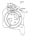
ここで、図4に示されるように、ロックリング214は、初期状態でストッパパウル218の先端が係合凹部224よりも巻取方向側でロックリング214の外周部に圧接するようにセットされる。
この状態からロックリング214が引出方向に回転すると、図5に示されるように、ロックリング214は引出方向に約一回転して、ストッパパウル218の先端と係合凹部224とが対向する。但し、この状態では、規制片242が係合凹部224の開口側に位置している。このため、ストッパパウル218の先端は、係合凹部224と対向しても、規制片242の規制片本体244に圧接して、係合凹部224の内側へ入り込むことはできない。
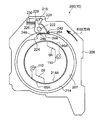
この状態で更にロックリング214が引出方向に回転すると、図6に示されるように、ストッパパウル218の先端が、規制片242における当接部254の先端側に当接する。これによって、規制片242は引出方向側への移動(回動)が規制される。したがって、この状態で更にロックリング214が引出方向に回転すると、規制片242の嵌挿部248が嵌挿孔250から引抜かれ、ロックリング214の外周面に摺接する。
この状態で更にロックリング214が引出方向に一回転して、規制片242が係合凹部224に対向すると、図7に示されるように、規制片242は係合凹部224の内側に入り込み、更に、ストッパパウル218の先端が係合凹部224の内側に入り込む。これによって、ロックリング214は引出方向への回転が規制される。このように、ロックリング214の引出方向への回転が規制されることにより、サブトーションシャフト24はスリーブ側係合部52の引出方向への回転が規制される。
したがって、この状態ではスプール14は、引出方向の回転力がメイントーションシャフト20のメインエネルギー吸収部44の機械的強度と、サブトーションシャフト24のサブエネルギー吸収部54の機械的強度との和を上回っていれば引出方向に回転できる。これにより、メイントーションシャフト20のメインエネルギー吸収部44だけが捩じり変形がされていた状態よりも、引出方向の大きなエネルギーを吸収できる。
しかも、上述したように、本実施の形態に係るウェビング巻取装置10では、ロックリング214が引出方向に回転を開始してから、ストッパパウル218の先端の側方を係合凹部224が1回通過し、その後に再びストッパパウル218の先端の側方に係合凹部224が到達するまでロックリング214は引出方向の回転が規制されない。これにより、メイントーションシャフト20の捩じり変形が開始されてからサブトーションシャフト24の捩じり変形が開始されるまでに要するスプール14の回転数は1回転を超える。
<第2の実施の形態の構成>
次に、第2の実施の形態について説明する。
次に、第2の実施の形態について説明する。
図9には本実施の形態に係るウェビング巻取装置260の要部の構成が前記第1の実施の形態を説明する際に用いた図4に対応する側面図によって示されている。
この図に示されるように、ウェビング巻取装置260は規制部材262を備えている。図8の斜視図に示されるように、規制部材262は規制部材本体264を備えている。規制部材本体264はロックリング214の外周部に倣って湾曲した細幅板状に形成されている。図9に示されるように、規制部材本体264は、ロックリング214の外周部の外側でロックリング214の外周部に沿って配置される。また、規制部材本体264の引出方向側の端部には当接片266が形成されている。当接片266は規制部材本体264の曲率半径方向外側へ延出されている。
さらに、図8及び図9に示されるように、規制部材本体264の幅方向一端には縦壁268が形成されている。図9に示されるように、縦壁268は規制部材本体264の幅方向一端から規制部材本体264の曲率半径方向内側に延出されている。縦壁268は、規制部材本体264がロックリング214の外周部に沿って配置された状態で、ロックリング214の脚板30側の面の側方に位置する。図8に示されるように、この縦壁268からはシェアピン270がロックリング214側へ向けて突出形成されている。このシェアピン270はロックリング2214に形成された孔部272(図9参照)に嵌め込まれている。これによって、規制部材262はロックリング2214に連結され、ロックリング2214と一体に回転できる。
また、図9に示されるように、シェアピン270が孔部272に嵌め込まれた状態では、規制部材262は規制部材本体264の巻取方向側の部分が係合凹部224をその開口側から蓋をするように係合凹部224の開口側に位置している。また、規制部材本体264の引出方向側の端部には当接片266が形成されている。当接片266は規制部材本体264の曲率半径方向外側へ延出されている。
一方、ボデー2206には扇孔部274が形成されている。扇孔部274は円孔208(図2参照)よりも曲率半径が大きく、円孔208と同心の扇状に形成されている。この扇孔部274の内側には当接片266が入り込む。当接片266は扇孔部274の内側でロックリング2214と共に回転可能である。この扇孔部274の引出方向側の端部は当接部276とされている。規制部材262は当接片266が当接部276に当接することによって引出方向への回転が規制される。
図11に示されるように、規制部材本体264は、当接片266が当接部276に当接した状態で、その巻取方向側の端部がストッパパウル218の先端よりも引出方向側に位置するように周方向(長手方向)の長さが設定されている。このため、当接片266が当接部276に当接した状態で、ロックリング214だけが引出方向に回転して、係合凹部224がストッパパウル218の先端の側方に位置すると、図13に示されるように、ストッパパウル218の先端が係合凹部224に入り込むことができる。
<第2の実施の形態の作用、効果>
図9に示される初期状態では、ストッパパウル218の先端が、係合凹部224よりも引出方向側で規制部材本体264の外面に圧接している。この状態で、クラッチプレート66のローレット部66Aがロックリング214のローレット部214Aと噛み合い、スプール14と共にロックリング214が引出方向に回転すると、規制部材262がロックリング214と共に引出方向に回転する。この状態では、規制部材本体264の巻取方向側の部分が係合凹部224の開口側に位置している。このため、図10に示されるように、ストッパパウル218の先端が係合凹部224と対向しても、ストッパパウル218の先端は係合凹部224に入り込むことができない。
図9に示される初期状態では、ストッパパウル218の先端が、係合凹部224よりも引出方向側で規制部材本体264の外面に圧接している。この状態で、クラッチプレート66のローレット部66Aがロックリング214のローレット部214Aと噛み合い、スプール14と共にロックリング214が引出方向に回転すると、規制部材262がロックリング214と共に引出方向に回転する。この状態では、規制部材本体264の巻取方向側の部分が係合凹部224の開口側に位置している。このため、図10に示されるように、ストッパパウル218の先端が係合凹部224と対向しても、ストッパパウル218の先端は係合凹部224に入り込むことができない。
この状態でロックリング2214が更に引出方向に回転すると規制部材262がストッパパウル218の先端よりも引出方向に回転し、ストッパパウル218の先端は規制部材本体264の外面から脱落してロックリング2214の外周面に圧接される。さらに、この状態からロックリング2214が引出方向に回転すると、図11に示されるように、規制部材262の当接片266がボディ2206の当接部276に当接する。これによって、規制部材262は引出方向への回転が規制される。この状態からロックリング2214が更に引出方向に回転すると、図12に示されるように、シェアピン270は破断される。これにより、規制部材262とロックリング2214との連結が解消される。このため、これより後は、ロックリング2214だけが引出方向に回転して、規制部材262は引出方向に回転しない。
この状態から更にロックリング2214が引出方向に回転することにより、図13に示されるように、ロックリング214の係合凹部224がストッパパウル218の先端と対向すると、ストッパパウル218の先端が係合凹部224に入り込む。これによって、ロックリング2214は引出方向への回転が規制される。このように、ロックリング2214の引出方向への回転が規制されることにより、サブトーションシャフト24はスリーブ側係合部52の引出方向への回転が規制され、スプール14が引出方向に回転することによりサブトーションシャフト24のサブエネルギー吸収部54においても捩じり変形が開始される。
このように、本実施の形態に係るウェビング巻取装置260でも、ロックリング2214が引出方向に回転を開始してから、ストッパパウル218の先端の側方を係合凹部224が1回通過し、その後に再びストッパパウル218の先端の側方に係合凹部224が到達するまでロックリング2214は引出方向の回転が規制されない。これにより、メイントーションシャフト20の捩じり変形が開始されてからサブトーションシャフト24の捩じり変形が開始されるまでに要するスプール14の回転数は1回転を超える。
<第3の実施の形態の構成>
次に、第3の実施の形態について説明する。
次に、第3の実施の形態について説明する。
図15には本実施の形態に係るウェビング巻取装置290の要部の構成が前記第1の実施の形態を説明する際に用いた図4に対応する側面図によって示されている。
この図に示されるように、ウェビング巻取装置290は規制部材としての規制片292を備えている。図14の斜視図に示されるように、規制片292は長手方向がロックリング214の回転接線方向に沿った細幅板状に形成されており、図15に示されるように、ストッパパウル218の先端とロックリング214の外周部との間に配置されている。規制片292の一端はボデー3206に形成された収容孔294に入り込んでいる。収容孔294はロックリング収容部207の内周部にて開口しており、規制片292の大部分を収容できる。但し、収容孔294の入口側にはシェア壁296が形成されており、規制片292の一端はシェア壁296に当接している。これにより、規制片292は、シェア壁296を破断しないと、それ以上収容孔294の奥へ入り込むことができない。
一方、図14に示されるように、規制片292の他端側には切欠部298が形成されている。切欠部298は規制片292の長手方向他端部にて開口していると共に、規制片292の厚さ方向に貫通している。さらに、規制片292には弾性当接部300が形成されている。弾性当接部300は切欠部298の底部から規制片292の長手方向他端側への方向に対してロックリング214の半径方向内側へ傾斜する方向へ延出されている。さらに、弾性当接部300は、その長手方向中間部にて屈曲され、この屈曲部分よりも先端側は規制片292の長手方向他端側への方向に対して規制片292の本体部分側へ延びている。
<第3の実施の形態の作用、効果>
図15に示される初期状態では、規制片292の他端側は弾性当接部300と共にロックリング収容部207の内周部とロックリング214の外周部との間の隙間に位置している。この状態で、クラッチプレート66のローレット部66Aがロックリング214のローレット部214Aと噛み合い、ロックリング214がスプール14と共に引出方向に回転する。これによって、係合凹部224が弾性当接部300と対向すると、図16に示されるように、弾性当接部300は弾性的な復元力で係合凹部224の内側に入り込む。
図15に示される初期状態では、規制片292の他端側は弾性当接部300と共にロックリング収容部207の内周部とロックリング214の外周部との間の隙間に位置している。この状態で、クラッチプレート66のローレット部66Aがロックリング214のローレット部214Aと噛み合い、ロックリング214がスプール14と共に引出方向に回転する。これによって、係合凹部224が弾性当接部300と対向すると、図16に示されるように、弾性当接部300は弾性的な復元力で係合凹部224の内側に入り込む。
また、この状態では、規制片292がストッパパウル218の先端とロックリング214の外周部との間に介在している。このため、ストッパパウル218の先端が係合凹部224と対向しても、ストッパパウル218の先端は係合凹部224に入り込むことができない。
さらに、この状態からロックリング214が引出方向に回転すると、係合凹部224の内壁が弾性当接部300の先端を押圧する。これにより規制片292の一端が収容孔294に形成されたシェア壁296を押圧するとシェア壁296が破断される。この状態で弾性当接部300の先端が更に係合凹部224の内壁に押圧されると、図17に示されるように、規制片292は、その大部分が収容孔294の奥へ押し込まれる。
この状態で、ロックリング214が更に引出方向に約一回転して、係合凹部224がストッパパウル218の先端と対向した状態では、ストッパパウル218の先端と係合凹部224との間に規制片292は介在していない。このため、図18に示されるように、ストッパパウル218の先端が係合凹部224に入り込む。これによって、ロックリング214は引出方向への回転が規制される。このように、ロックリング214の引出方向への回転が規制されることにより、サブトーションシャフト24はスリーブ側係合部52の引出方向への回転が規制され、スプール14が引出方向に回転することによりサブトーションシャフト24のサブエネルギー吸収部54においても捩じり変形が開始される。
このように、本実施の形態に係るウェビング巻取装置290でも、ロックリング214が引出方向に回転を開始してから、ストッパパウル218の先端の側方を係合凹部224が1回通過し、その後に再びストッパパウル218の先端の側方に係合凹部224が到達するまでロックリング214は引出方向の回転が規制されない。これにより、メイントーションシャフト20の捩じり変形が開始されてからサブトーションシャフト24の捩じり変形が開始されるまでに要するスプール14の回転数は1回転を超える。
<第4の実施の形態の構成>
次に、第4の実施の形態について説明する。
次に、第4の実施の形態について説明する。
図20には本実施の形態に係るウェビング巻取装置320の要部の構成が前記第1の実施の形態を説明する際に用いた図4に対応する側面図によって示されている。
この図に示されるように、ウェビング巻取装置320は、ロックリング214に代わる回転体としてのロックリング322を備えている。ロックリング322には係合凹部224が形成されておらず、代わりに係合部としての係合凸部324が形成されている。係合凸部324はロックリング322の外周部から半径方向外側へ延出されている。係合凸部324は巻取方向側が斜面326とされており、この斜面326ではロックリング322の中心から斜面326までの径寸法が巻取方向側へ向けて漸次短くなっている。ロックリング322は、ストッパパウル218の先端が引出方向側から係合凸部324に当接することによって引出方向への回転が規制される。
また、図19に示されるように、ボディ4206のロックリング収容部207の底壁328には矩形の貫通孔330が形成されている。貫通孔330の内周部における巻取方向側の端部からは規制部材としての弾性片332が延出されている。弾性片332は長手方向が貫通孔330の内周部からの延出方向とされ、厚さ方向が底壁328の厚さ方向とされた細幅板状とされている。弾性片332は、その先端が自由端とされ、図24に示されるように、幅方向を軸方向とする軸周りに弾性変形可能とされている。
図19に示されるように、弾性片332の先端には支持突起334が形成されている。支持突起334は弾性片332の先端からロックリング収容部207の内側へ突出するように形成されている。図20に示されるように、支持突起334の上面にはストッパパウル218の先端がロックリング322の係合凸部324の外面よりも更にロックリング322の半径方向外側で圧接している。また支持突起334は、ロックリング収容部207の内側に入り込んでおり、ロックリング322の回転による係合凸部324の回転軌跡上に位置している。
<第4の実施の形態の作用、効果>
図20に示される初期状態で、クラッチプレート66のローレット部66Aがロックリング322のローレット部214Aと噛み合うと、スプール14と共にロックリング322が引出方向に回転する。このようにロックリング322が引出方向に約一回転することによって、図22に示されるように、ロックリング322の係合凸部324と弾性片332の支持突起334とがロックリング322の軸方向に対向すると、図22および図23に示されるように、支持突起334が係合凸部324に押圧されて弾性片332がロックリング収容部207の開口側とは反対側へ弾性変形する。このように、弾性片332が弾性変形すると、支持突起334の上面とストッパパウル218の先端との対向状態が解消される。これによって、ストッパパウル218の先端は、支持突起334による支持を失い、係合凸部324の外面に圧接する。
図20に示される初期状態で、クラッチプレート66のローレット部66Aがロックリング322のローレット部214Aと噛み合うと、スプール14と共にロックリング322が引出方向に回転する。このようにロックリング322が引出方向に約一回転することによって、図22に示されるように、ロックリング322の係合凸部324と弾性片332の支持突起334とがロックリング322の軸方向に対向すると、図22および図23に示されるように、支持突起334が係合凸部324に押圧されて弾性片332がロックリング収容部207の開口側とは反対側へ弾性変形する。このように、弾性片332が弾性変形すると、支持突起334の上面とストッパパウル218の先端との対向状態が解消される。これによって、ストッパパウル218の先端は、支持突起334による支持を失い、係合凸部324の外面に圧接する。
この状態でロックリング322が更に引出方向に回転して、係合凸部324の斜面326がストッパパウル218の先端と対向すると、ストッパパウル218の先端は斜面326に圧接する。この状態でロックリング322が引出方向に回転すると、図24に示されるように、ストッパパウル218の先端は斜面326に倣うように漸次ロックリング322の回転半径方向内側へ回動する。この状態では、ストッパパウル218がロックリング322の軸方向に支持突起334と対向する。このため、支持突起334はストッパパウル218に圧接して、弾性片332は、その弾性的な復元力で元の状態に戻ることができない。
この状態から更にロックリング322が引出方向に約一回転すると、ストッパパウル218の先端が係合凸部324の引出方向側で係合凸部324と対向し、図25に示されるように、ストッパパウル218の先端が係合凸部324に当接する。これによって、ロックリング322は引出方向への回転が規制される。このように、ロックリング322の引出方向への回転が規制されることにより、サブトーションシャフト24はスリーブ側係合部52の引出方向への回転が規制され、スプール14が引出方向に回転することによりサブトーションシャフト24のサブエネルギー吸収部54においても捩じり変形が開始される。
このように、本実施の形態に係るウェビング巻取装置320でも、ロックリング322が引出方向に回転を開始してから、ストッパパウル218の先端の側方を係合凸部324が1回通過し、その後にストッパパウル218の先端が引出方向側から係合凸部324に当接するまでロックリング322は引出方向の回転が規制されない。これにより、メイントーションシャフト20の捩じり変形が開始されてからサブトーションシャフト24の捩じり変形が開始されるまでに要するスプール14の回転数は1回転を超える。
日本出願2013-084172の開示はその全体が参照により本明細書に取り込まれる。
本明細書に記載された全ての文献、特許出願、及び技術規格は、個々の文献、特許出願、及び技術規格が参照により取り込まれることが具体的にかつ個々に記載された場合と同様に、本明細書中に参照により取り込まれる。
本明細書に記載された全ての文献、特許出願、及び技術規格は、個々の文献、特許出願、及び技術規格が参照により取り込まれることが具体的にかつ個々に記載された場合と同様に、本明細書中に参照により取り込まれる。
Claims (7)
- ウェビングを巻取るスプールと、
前記スプールの軸方向一端側で前記スプールに対して相対回転可能に設けられたロックベースと、
前記スプールが前記ロックベースに対して引出方向に相対回転することにより変形する第1エネルギー吸収部材と、
一端が前記スプールに対する相対回転が規制された状態で前記スプールに繋がり、他端に対して一端が引出方向に相対回転することにより変形する第2エネルギー吸収部材と、
前記スプールの軸方向他端側に設けられて、前記スプールに対して同軸的に回転可能な回転体と、
前記スプールが前記ロックベースに対して引出方向に回転することにより作動して、前記回転体を前記第2エネルギー吸収部材の他端に連結する連結手段であって、これにより前記第2エネルギー吸収部材の他端と前記回転体とは一体的に引出方向へ回転可能となり、
前記回転体の側方に設けられると共に、前記回転体に接近する方向へ移動可能とされ、前記回転体に接近して前記回転体に形成された係合部に係合することにより前記回転体が引出方向に回転することを規制するロック部材と、
前記ロック部材が前記係合部に係合する位置まで移動することを規制すると共に、前記回転体が引出方向に1回転した後に前記ロック部材に対する移動規制を解除する規制部材と、
を備えるウェビング巻取装置。 - 前記係合部は、前記回転体の外周部にて開口した係合凹部とされて、前記回転体は前記ロック部材が前記係合凹部に入り込むことにより引出方向への回転が規制され、
前記規制部材は、前記回転体と共に回転可能に前記係合凹部の外側に設けられて前記ロック部材が前記係合凹部に入り込むことを規制し、前記回転体の1回転目で前記係合凹部が前記ロック部材の側方に到達し、又は、前記ロック部材の側方を通過した後に、前記規制部材の引出方向への回転が規制され、この状態で前記回転体が引出方向に回転することにより、前記規制部材が前記係合凹部の外側から離れて前記ロック部材に対する移動規制を解除する、請求項1に記載のウェビング巻取装置。 - 前記ロック部材は、前記回転体の外周部に接近する方向へ付勢されて前記回転体の外周部に圧接し、
前記規制部材は、前記ロック部材が前記規制部材に係合することにより引出方向への回転が規制され、前記回転体が1回転した後に前記ロック部材と共に前記係合凹部に入り込み前記ロック部材に対する移動規制を解除する、請求項2に記載のウェビング巻取装置。 - ウェビング巻き取り装置は更に支持部材を備え、
前記ロック部材は、前記回転体の外周部に接近する方向へ移動可能に支持部材に支持されると共に前記回転体の外周部に接近する方向へ付勢されて、
前記規制部材は、前記回転体の1回転目で前記係合凹部が前記ロック部材の側方を通過した後に前記支持部材の所定部位に当接して引出方向への回転が規制される、請求項2に記載のウェビング巻取装置。 - 前記係合部は、前記回転体の外周部にて開口した係合凹部とされて、前記回転体は前記ロック部材が前記係合凹部に入り込むことにより引出方向への回転が規制され、
前記ロック部材は、前記回転体の外周部に接近する方向へ付勢され、
前記規制部材は、前記係合凹部の外側に設けられ、前記回転体の1回転目で前記規制部材の一部が前記回転体に係合し前記回転体に押圧され、前記係合凹部が前記ロック部材の側方を通過した後に前記係合凹部の外側から離れる方向へ移動して前記ロック部材に対する移動規制を解除する、請求項1に記載のウェビング巻取装置。 - 前記係合部は、前記回転体の外周部から前記回転体の外側へ突出した係合凸部とされて、前記回転体は前記ロック部材が引出方向側から前記係合凸部に当接することにより引出方向への回転が規制され、
前記規制部材は、前記回転体の回転による前記係合凸部の回転軌跡上に設けられ、前記ロック部材を支持して前記ロック部材の移動を規制すると共に、前記回転体の1回転目で、引出方向に回転した前記回転体の係合凸部と対向することにより前記係合凸部に押圧されて変位して前記ロック部材の支持を解消し、
前記ロック部材は、前記回転体の外周部に接近する方向へ付勢され、前記規制部材による支持が解消されることで前記係合凸部の半径方向外側面に圧接し、更に前記回転体が引出方向に回転することにより前記回転体の外周部に接近し、前記回転体の係合凸部と当接可能となる、請求項1に記載のウェビング巻取装置。 - ウェビング巻き取り装置は更に支持部材を備え、
前記規制部材は、前記支持部材に設けられた弾性片であり、前記ロック部材に向かって付勢されて前記ロック部材を支持して移動を規制する、請求項6に記載のウェビング巻取装置。
Priority Applications (1)
| Application Number | Priority Date | Filing Date | Title |
|---|---|---|---|
| US14/783,149 US9914430B2 (en) | 2013-04-12 | 2014-04-02 | Webbing take-up device |
Applications Claiming Priority (2)
| Application Number | Priority Date | Filing Date | Title |
|---|---|---|---|
| JP2013-084172 | 2013-04-12 | ||
| JP2013084172A JP6113562B2 (ja) | 2013-04-12 | 2013-04-12 | ウェビング巻取装置 |
Publications (1)
| Publication Number | Publication Date |
|---|---|
| WO2014168063A1 true WO2014168063A1 (ja) | 2014-10-16 |
Family
ID=51689473
Family Applications (1)
| Application Number | Title | Priority Date | Filing Date |
|---|---|---|---|
| PCT/JP2014/059776 Ceased WO2014168063A1 (ja) | 2013-04-12 | 2014-04-02 | ウェビング巻取装置 |
Country Status (3)
| Country | Link |
|---|---|
| US (1) | US9914430B2 (ja) |
| JP (1) | JP6113562B2 (ja) |
| WO (1) | WO2014168063A1 (ja) |
Families Citing this family (5)
| Publication number | Priority date | Publication date | Assignee | Title |
|---|---|---|---|---|
| JP6566725B2 (ja) * | 2015-05-28 | 2019-08-28 | Joyson Safety Systems Japan株式会社 | シートベルトリトラクタ及びシートベルト装置 |
| JP6576794B2 (ja) * | 2015-11-05 | 2019-09-18 | 株式会社東海理化電機製作所 | ウェビング巻取装置 |
| JP6576795B2 (ja) * | 2015-11-05 | 2019-09-18 | 株式会社東海理化電機製作所 | ウェビング巻取装置 |
| JP6694777B2 (ja) * | 2016-08-01 | 2020-05-20 | 株式会社東海理化電機製作所 | ウェビング巻取装置 |
| JP2025073310A (ja) * | 2023-10-26 | 2025-05-13 | 株式会社東海理化電機製作所 | ウェビング巻取装置 |
Citations (6)
| Publication number | Priority date | Publication date | Assignee | Title |
|---|---|---|---|---|
| WO1998036951A1 (en) * | 1997-02-19 | 1998-08-27 | Breed Automotive Technology, Inc. | Multi-level load limiting torsion bar retractor |
| JP2002503586A (ja) * | 1998-02-19 | 2002-02-05 | ブリード オートモティブ テクノロジィ、 インク. | 荷重制限シートベルトレトラクタ |
| JP2012096745A (ja) * | 2010-11-05 | 2012-05-24 | Tokai Rika Co Ltd | ウェビング巻取装置 |
| JP2012144123A (ja) * | 2011-01-11 | 2012-08-02 | Tokai Rika Co Ltd | ウェビング巻取装置 |
| JP2013001313A (ja) * | 2011-06-20 | 2013-01-07 | Tokai Rika Co Ltd | ウェビング巻取装置 |
| JP2013060135A (ja) * | 2011-09-14 | 2013-04-04 | Tokai Rika Co Ltd | ウェビング巻取装置 |
Family Cites Families (2)
| Publication number | Priority date | Publication date | Assignee | Title |
|---|---|---|---|---|
| JP5714617B2 (ja) * | 2013-01-22 | 2015-05-07 | 株式会社東海理化電機製作所 | ウェビング巻取装置。 |
| JP5961570B2 (ja) * | 2013-02-22 | 2016-08-02 | 株式会社東海理化電機製作所 | ウェビング巻取装置 |
-
2013
- 2013-04-12 JP JP2013084172A patent/JP6113562B2/ja not_active Expired - Fee Related
-
2014
- 2014-04-02 WO PCT/JP2014/059776 patent/WO2014168063A1/ja not_active Ceased
- 2014-04-02 US US14/783,149 patent/US9914430B2/en active Active
Patent Citations (6)
| Publication number | Priority date | Publication date | Assignee | Title |
|---|---|---|---|---|
| WO1998036951A1 (en) * | 1997-02-19 | 1998-08-27 | Breed Automotive Technology, Inc. | Multi-level load limiting torsion bar retractor |
| JP2002503586A (ja) * | 1998-02-19 | 2002-02-05 | ブリード オートモティブ テクノロジィ、 インク. | 荷重制限シートベルトレトラクタ |
| JP2012096745A (ja) * | 2010-11-05 | 2012-05-24 | Tokai Rika Co Ltd | ウェビング巻取装置 |
| JP2012144123A (ja) * | 2011-01-11 | 2012-08-02 | Tokai Rika Co Ltd | ウェビング巻取装置 |
| JP2013001313A (ja) * | 2011-06-20 | 2013-01-07 | Tokai Rika Co Ltd | ウェビング巻取装置 |
| JP2013060135A (ja) * | 2011-09-14 | 2013-04-04 | Tokai Rika Co Ltd | ウェビング巻取装置 |
Also Published As
| Publication number | Publication date |
|---|---|
| US20160046260A1 (en) | 2016-02-18 |
| JP2014205421A (ja) | 2014-10-30 |
| JP6113562B2 (ja) | 2017-04-12 |
| US9914430B2 (en) | 2018-03-13 |
Similar Documents
| Publication | Publication Date | Title |
|---|---|---|
| JP4885764B2 (ja) | ウエビング巻取装置 | |
| JP5566858B2 (ja) | ウェビング巻取装置 | |
| US8439291B2 (en) | Webbing winding device | |
| US9688240B2 (en) | Seat belt retractor | |
| EP1902911B1 (en) | Webbing retractor device | |
| JP6113562B2 (ja) | ウェビング巻取装置 | |
| JP6045933B2 (ja) | シートベルト用リトラクタ | |
| JP5714617B2 (ja) | ウェビング巻取装置。 | |
| WO2012165410A1 (ja) | シートベルト用リトラクタ | |
| CN103661238B (zh) | 安全带卷取装置 | |
| JP5961570B2 (ja) | ウェビング巻取装置 | |
| JP5714624B2 (ja) | ウェビング巻取装置 | |
| JP5203881B2 (ja) | ウエビング巻取装置 | |
| JP5529076B2 (ja) | ウエビング巻取装置 | |
| JP5990481B2 (ja) | ウェビング巻取装置 | |
| JP5819255B2 (ja) | ウェビング巻取装置 | |
| JP5641882B2 (ja) | ウェビング巻取装置 | |
| JP5226541B2 (ja) | ウエビング巻取装置 | |
| KR101439373B1 (ko) | 시트 벨트 리트랙터 클러치 | |
| JP2003212089A (ja) | ウエビング巻取装置 | |
| KR102386889B1 (ko) | 시트벨트용 리트랙터 | |
| KR101675755B1 (ko) | 시트벨트 클러치 및 시트벨트 리트렉터 | |
| JP2013049401A (ja) | ウェビング巻取装置 | |
| JP5263626B2 (ja) | シートベルト用リトラクタ |
Legal Events
| Date | Code | Title | Description |
|---|---|---|---|
| 121 | Ep: the epo has been informed by wipo that ep was designated in this application |
Ref document number: 14782095 Country of ref document: EP Kind code of ref document: A1 |
|
| WWE | Wipo information: entry into national phase |
Ref document number: 14783149 Country of ref document: US |
|
| NENP | Non-entry into the national phase |
Ref country code: DE |
|
| 122 | Ep: pct application non-entry in european phase |
Ref document number: 14782095 Country of ref document: EP Kind code of ref document: A1 |