WO2014156981A1 - 位相差フィルムの製造方法 - Google Patents
位相差フィルムの製造方法 Download PDFInfo
- Publication number
- WO2014156981A1 WO2014156981A1 PCT/JP2014/057819 JP2014057819W WO2014156981A1 WO 2014156981 A1 WO2014156981 A1 WO 2014156981A1 JP 2014057819 W JP2014057819 W JP 2014057819W WO 2014156981 A1 WO2014156981 A1 WO 2014156981A1
- Authority
- WO
- WIPO (PCT)
- Prior art keywords
- film
- support
- coating film
- alignment
- liquid crystal
- Prior art date
- Legal status (The legal status is an assumption and is not a legal conclusion. Google has not performed a legal analysis and makes no representation as to the accuracy of the status listed.)
- Ceased
Links
Images


Classifications
-
- G—PHYSICS
- G02—OPTICS
- G02B—OPTICAL ELEMENTS, SYSTEMS OR APPARATUS
- G02B5/00—Optical elements other than lenses
- G02B5/30—Polarising elements
- G02B5/3083—Birefringent or phase retarding elements
-
- G—PHYSICS
- G02—OPTICS
- G02F—OPTICAL DEVICES OR ARRANGEMENTS FOR THE CONTROL OF LIGHT BY MODIFICATION OF THE OPTICAL PROPERTIES OF THE MEDIA OF THE ELEMENTS INVOLVED THEREIN; NON-LINEAR OPTICS; FREQUENCY-CHANGING OF LIGHT; OPTICAL LOGIC ELEMENTS; OPTICAL ANALOGUE/DIGITAL CONVERTERS
- G02F1/00—Devices or arrangements for the control of the intensity, colour, phase, polarisation or direction of light arriving from an independent light source, e.g. switching, gating or modulating; Non-linear optics
- G02F1/01—Devices or arrangements for the control of the intensity, colour, phase, polarisation or direction of light arriving from an independent light source, e.g. switching, gating or modulating; Non-linear optics for the control of the intensity, phase, polarisation or colour
- G02F1/13—Devices or arrangements for the control of the intensity, colour, phase, polarisation or direction of light arriving from an independent light source, e.g. switching, gating or modulating; Non-linear optics for the control of the intensity, phase, polarisation or colour based on liquid crystals, e.g. single liquid crystal display cells
- G02F1/133—Constructional arrangements; Operation of liquid crystal cells; Circuit arrangements
- G02F1/1333—Constructional arrangements; Manufacturing methods
- G02F1/1335—Structural association of cells with optical devices, e.g. polarisers or reflectors
- G02F1/13363—Birefringent elements, e.g. for optical compensation
-
- G—PHYSICS
- G02—OPTICS
- G02F—OPTICAL DEVICES OR ARRANGEMENTS FOR THE CONTROL OF LIGHT BY MODIFICATION OF THE OPTICAL PROPERTIES OF THE MEDIA OF THE ELEMENTS INVOLVED THEREIN; NON-LINEAR OPTICS; FREQUENCY-CHANGING OF LIGHT; OPTICAL LOGIC ELEMENTS; OPTICAL ANALOGUE/DIGITAL CONVERTERS
- G02F2202/00—Materials and properties
- G02F2202/28—Adhesive materials or arrangements
Definitions
- the present invention relates to a method for producing a retardation film having an optically anisotropic layer in which a liquid crystal compound is aligned.
- liquid crystal display devices In recent years, the use of liquid crystal display devices is rapidly advancing and is used in mobile phones, personal computer monitors, televisions, liquid crystal projectors, and the like.
- a liquid crystal display device has a display mode such as a TN (Twisted Nematic) mode, a VA (Vertical Alignment) mode, an IPS (In-Plane Switching) mode, an OCB (Optically ens Compensatory Bend) mode, and an ECB (Electrically Controlled Birefringence) mode.
- TN Transmission Nematic
- VA Very Alignment
- IPS In-Plane Switching
- OCB Optically ens Compensatory Bend
- ECB Electrically Controlled Birefringence
- a TFT (Thin Film Transistor) -LCD As such a liquid crystal display device, a TFT (Thin Film Transistor) -LCD is generally known.
- TFT Thin Film Transistor
- IPS mode liquid crystal display device
- the IPS mode is often adopted as a display for a tablet PC or the like, and the brightness of the screen is greatly improved. For this reason, a slight light leakage in the diagonal direction at the time of black display, which has not been regarded as a problem in the past, has become apparent as a cause of a decrease in display quality.
- Patent Document 1 discloses that a coating liquid in which a rod-like polymerizable liquid crystal compound is dissolved in an organic solvent is applied onto a support having an intermediate layer, and the coating liquid is dried. A method for forming an optically anisotropic layer by heating the coating solution and irradiating the heated coating solution with actinic radiation to cure it is described.
- Patent Document 2 a blocking layer and an intermediate layer are formed on a support, a coating liquid containing a liquid crystal compound is applied thereon, and the temperature of the coating liquid is increased to a phase transition temperature or higher. And a method of forming an optically anisotropic layer through a drying, heat treatment, and curing step that is maintained below the phase transition temperature.
- an intermediate layer is often provided on the support and a liquid crystal phase is formed on the intermediate layer in many cases. This is because the intermediate layer has a function of aligning the liquid crystal and a function of preventing the support composition component from diffusing into the liquid crystal film.
- liquid crystal vertical alignment film is directly formed on the support without using the intermediate layer, it is necessary to perform a special surface treatment such as a rubbing treatment or a plasma treatment on the surface of the support.
- This surface treatment may cause an increase in manufacturing cost and a decrease in quality due to contamination with dust and the like.
- an optically anisotropic layer also referred to as a liquid crystal layer
- the adhesiveness adheresive force
- the problem of peeling off of the layer became apparent. It is considered that the lack of adhesion occurs because there is no factor for bonding the support and the liquid crystal layer.
- the present invention has been made in consideration of such problems, and provides a method for producing a retardation film with improved adhesion between a support and an optically anisotropic layer and less liquid crystal alignment failure. With the goal.
- a method for producing a retardation film includes a step of preparing a belt-like support containing a plasticizer and / or an optical property adjusting agent, and a rod-like polymerizable liquid crystal on a continuously running support.
- a drying process for fixing the position of the alignment control agent and the alignment auxiliary agent and forming a coating film in which the solvent is impregnated into the support by 0.3 ⁇ m or more, and the internal temperature of the coating film is the alignment control agent A heat treatment step of heating the coating film for 25 seconds or more so that the alignment auxiliary agent is moved to the surface of the coating film, and after the heat treatment step, the internal temperature of the coating film is set to the position of the alignment control agent and the alignment auxiliary agent.
- Cooling process for cooling to a fixed temperature and after the cooling process 3 is irradiated to the coating film of the residual solvent ratio of less than mass% with active radiation to cure the coating, including a curing step of forming an optically anisotropic layer.
- the solvent contained in the raw material liquid has a solubility parameter SP value within a range of ⁇ 2 [(J / cm 3 ) 1/2 ] with respect to the solubility parameter SP value of the support material.
- the raw material liquid contains a plurality of other solvents in addition to the solvent that dissolves and swells the support.
- the drying step includes a step of drying the film at a drying rate of 0.1 [g / m 2 ⁇ sec] or less.
- the support is a cellulosic film.
- the adhesiveness between the support and the optically anisotropic layer is improved, and a retardation film with few liquid crystal alignment defects can be produced.
- FIG. 1 is a schematic configuration diagram of a retardation film manufacturing facility.
- FIG. 2A is an explanatory diagram showing the action of a liquid crystal compound, an alignment controller, and an alignment aid.
- FIG. 2B is an explanatory diagram showing the action of the liquid crystal compound, the alignment controller, and the alignment aid.
- FIG. 2C is an explanatory diagram showing the action of the liquid crystal compound, the alignment control agent, and the alignment aid.
- FIG. 2D is an explanatory diagram showing the action of the liquid crystal compound, the alignment controller, and the alignment aid.
- FIG. 3 is a table showing the results of the examples.
- FIG. 4 is a table showing the results of the examples.
- the method for producing a retardation film includes a step of preparing a belt-like support containing a plasticizer and / or an optical property adjusting agent, and a rod-like polymerizable liquid crystal compound and alignment control on the continuously running support.
- a raw material solution in which an agent and an alignment aid are dissolved in a solvent for dissolving or swelling the support to form a film By applying a raw material solution in which an agent and an alignment aid are dissolved in a solvent for dissolving or swelling the support to form a film, and by drying the film applied on the support, A drying process for forming a coating film in which the position of the control agent and the alignment aid is fixed and the solvent is soaked in the support by 0.3 ⁇ m or more, and the internal temperature of the coating film is the alignment control agent and the alignment aid.
- a raw material liquid containing a polymerizable liquid crystal compound, an alignment controller, and an alignment aid is prepared using a solvent that dissolves or swells the support. .
- a solvent that dissolves or swells the support the solvent soaks into the support during the drying step, and a region where the support and the membrane are mixed is formed.
- the adhesiveness between the support and the optically anisotropic layer can be improved by irradiating with active rays and curing.
- the penetration thickness 0.3 ⁇ m or more is impregnated so as to adhere more firmly.
- an optically anisotropic layer is formed with a raw material solution containing a solvent that dissolves or swells the support
- a plasticizer and / or an optical property adjuster that are components in the support are mixed in the optically anisotropic layer.
- the orientation of the coating film (liquid crystal film) after the drying step is hindered by the plasticizer and / or optical property modifier, and in particular, the support / optical anisotropy in which there are many plasticizers and / or optical property modifiers. Alignment at the interface portion of the film is hindered and alignment defects may occur.
- a heat treatment step is provided after the drying step to raise the temperature of the coating film and lower the viscosity.
- the liquid crystal compound in the coating film moves to make the coating film non-aligned, and the alignment control agent and the alignment aid are diffused to the coating film / air interface.
- the temperature of the coating film is lowered in the cooling step before irradiation with actinic radiation to increase the viscosity.
- the liquid crystal compound is reoriented while the movement of the liquid crystal compound in the coating film is moderated, and the diffusion of the alignment control agent and the alignment aid is stopped. It was found that an optically anisotropic layer (liquid crystal phase) free from alignment defects can be formed by curing the coating film by irradiation with active rays in this state.
- the alignment control agent plays a role of vertically aligning the liquid crystal compound and greatly contributes to the alignment on the support interface side.
- the orientation control agent contributes to the orientation on the air interface side, but the orientation regulating force is weak. Supporting this is an additive called an alignment aid.
- the alignment auxiliary agent plays a role of bringing the alignment control agent to the air interface side and unevenly distributing it.
- the alignment control agent moved to the air interface side contributes to the vertical alignment of the liquid crystal compound at the air interface. It is desirable to use a surfactant as an alignment aid.
- the coating film is dried and fixed before the alignment control agent and the alignment aid diffuse to the air interface side.
- the orientation control agent and the alignment aid diffuse again by reducing the viscosity of the coating film.
- the liquid crystal compound is vertically aligned due to the effect of the alignment control agent, but the alignment is partially inhibited at the interface portion of the support / coating film.
- the alignment of the liquid crystal compound in the coating film is once brought into the non-aligned state including the interface portion of the support / coating film in which the alignment inhibition has occurred.
- the liquid crystal compound is re-orientated by cooling before irradiation with actinic radiation.
- the alignment regulating force on the air interface side is strengthened, thereby supporting the alignment of the interface portion of the support / coating film. It is estimated that the orientation is improved as a whole.
- the heat treatment temperature needs to be a temperature at which the liquid crystal becomes non-aligned and the fixed alignment control agent and alignment aid diffuse again.
- the heat treatment time is set to 25 seconds or more, it is possible to secure the time necessary for breaking the alignment inhibition at the interface part of the support / coating film, and the alignment control agent and the alignment aid are sufficiently diffused to the air interface. Time can be secured. As a result, the alignment of the liquid crystal compound is improved.
- the cooling temperature needs to be a temperature at which the liquid crystal is aligned again and the alignment control agent and alignment aid are fixed again.
- the support is preferably a resin film that is optically transparent and has birefringence.
- Engineeringly transparent means having a transmittance of 60% or more, and a transmittance of 80% or more is more preferable.
- Rth ((n x ⁇ n y ) / 2 ⁇ n z ) ⁇ d (N z : refractive index in the thickness direction)
- Both Re and Rth are preferably 0 to 150 nm, particularly preferably 70 to 120 nm.
- the support is made of cellulose film (cellulose diacetate, cellulose triacetate, cellulose acetate butyrate, etc.), polyester film, polycarbonate film, polyester film (polyethylene terephthalate), polyethylene film, polypropylene film, polychlorinated film.
- the film include a polyvinyl film, a polyvinyl alcohol film, a polymethyl methacrylate film, an acrylic film, and a norbornene film.
- a cellulose ester film is desirable as such a material.
- the support includes a plasticizer for imparting desired physical performance and / or an optical property adjusting agent for imparting desired optical performance.
- the plasticizer is not particularly limited, and preferred examples include phthalate ester, phosphate ester, and resin acid.
- the optical property modifier is not particularly limited, and preferred examples thereof include optical compounds such as aromatic ring-containing compounds containing nitrogen compounds, liquid crystal compounds, and anisotropically shaped compounds as disclosed in JP-A-2012-234094. Examples include compounds having large anisotropy.
- the rod-like liquid crystal compound contained in the optically anisotropic layer is, for example, a rod-like nematic liquid crystal compound.
- rod-like nematic liquid crystal compounds include azomethines, azoxys, cyanobiphenyls, cyanophenyl esters, benzoic acid esters, cyclohexanecarboxylic acid phenyl esters, cyanophenylcyclohexanes, cyano-substituted phenylpyrimidines, and alkoxy-substituted phenylpyrimidines.
- Phenyldioxanes, tolanes and alkenylcyclohexylbenzonitriles are preferably used. Not only low-molecular liquid crystal compounds but also high-molecular liquid crystal compounds can be used.
- the polymerizable liquid crystal compound can be obtained by introducing a polymerizable group into the liquid crystal compound.
- the polymerizable group include an unsaturated polymerizable group, an epoxy group, and an aziridinyl group, preferably an unsaturated polymerizable group, and particularly preferably an ethylenically unsaturated polymerizable group.
- the polymerizable group can be introduced into the molecule of the liquid crystal compound by various methods.
- the number of polymerizable groups possessed by the polymerizable liquid crystal compound is preferably 1 to 6, more preferably 1 to 3.
- Examples of polymerizable liquid crystal compounds include Makromol. Chem., 190, 2255 (1989), Advanced Materials, 5, 107 (1993), US Pat. No.
- the amount of the polymerizable liquid crystal compound contained in the raw material liquid is preferably 10 to 50% by mass, more preferably 20 to 40% by mass, and particularly preferably 25 to 35% by mass. .
- the alignment control agent plays a role of vertically aligning the liquid crystal compound, and contributes to the alignment of the liquid crystal compound on the intermediate film interface side. That is, the molecules of the liquid crystal compound are substantially vertically aligned by the alignment control agent.
- the alignment control agent can align the molecules of the liquid crystal compound substantially vertically.
- Preferable examples include compounds represented by the following general formula. You may contain 2 or more types selected from these.
- a rod-like structure for vertically aligning the liquid crystal compound that is, the main chain is somewhat long
- a material having a hydrophilic group that easily binds to the intermediate film and the alignment aid are considered preferable.
- the —N—C 2 H 6 moiety in the following chemical formula (Chemical Formula 1) is considered to be related to the function of the orientation control agent.
- R represents an alkoxy group having 1 to 30 carbon atoms, more preferably an alkoxy group having 1 to 20 carbon atoms, and still more preferably an alkoxy group having 1 to 15 carbon atoms.
- one or more CH 2 and two or more CH 2 not adjacent to each other in the alkoxy group are —O—, —S—, —OCO—, —COO—, —NRa—, —NRaCO—, —CONRa—, It may be substituted with —NRaSO 2 — or —SO 2 NRa—.
- Ra represents a hydrogen atom or an alkyl group having 1 to 5 carbon atoms.
- the amount of the orientation control agent used is preferably 0.001 to 1% by mass, more preferably 0.005 to 0.5% by mass, and more preferably 0.01 to 0.1% by mass of the solid content of the raw material liquid. It is particularly preferable that the content is% by mass.
- the alignment auxiliary agent plays a role of bringing the alignment control agent to the air interface side to be unevenly distributed, and contributes to the vertical alignment of the liquid crystal compound at the air interface.
- the above-mentioned alignment control agent contributes to the alignment on the air interface side but does not have a strong alignment regulating force.
- the alignment aid supports alignment on the air interface side. It is desirable to use a surfactant as an alignment aid.
- the alignment aid is not particularly limited to this.
- the alignment auxiliary agent includes a group containing F having poor compatibility with the liquid crystal compound, a hydrophilic group for bonding with the alignment control agent, It is considered preferable to have For example, in chemical formulas 2 and 3 (general formulas (I) and (II)), the group containing F corresponds to the left group, and the hydrophilic group corresponds to the right -COOR- moiety. These are considered to be related to the function of the alignment aid.
- R represents an alkoxy group having 1 to 30 carbon atoms, more preferably an alkoxy group having 1 to 20 carbon atoms, and still more preferably an alkoxy group having 1 to 15 carbon atoms.
- a and b represent ratios contained in the compound.
- the amount of the alignment aid used is preferably 0.001 to 1% by mass, more preferably 0.005 to 0.5% by mass, based on the liquid crystal compound (solid content in the case of a raw material liquid).
- the content is preferably 0.01 to 0.1% by mass.
- solvent has a property of dissolving the liquid crystal compound and dissolving or swelling the support.
- solvents that dissolve or swell cellulose ester include methyl ethyl ketone, acetone, methyl acetate, ethyl acetate, methylene chloride, ethylene chloride, tetrachloroethane, trichloroethane, propylene glycol monomethyl ether, and propylene glycol monomethyl ether acetate.
- a plurality of solvents that dissolve or swell the support can also be combined.
- the swelling means a state in which the volume of the polymer substance such as a resin is expanded by maintaining the solid state shape of the polymer substance, and the solvent molecules having a relatively low molecular weight enter the gap between the polymer substances and penetrate.
- a polymer film having a thickness of 0.1 mm is immersed in a solvent for 10 minutes and the thickness is increased by 1% or more.
- the thickness can be measured with a film thickness tester (Anritsu KB601).
- Dissolution means a state in which a polymer chain surrounded by solvent molecules is separated and dispersed in a solvent.
- a polymer film of 50 mm ⁇ 50 mm ⁇ 0.1 mm is immersed in a solvent for 10 minutes. This means that the film weight decreases by 0.1% or more before and after immersion.
- the weight can be measured with an electronic balance (XS104 manufactured by Mettler-Toredo).
- solvents are preferable, for example, for controlling dissolution and swelling of the support.
- solvents there are alcohols (ethanol, methanol, n-butanol, i-propyl alcohol, n-propyl alcohol, etc.), hydrocarbons (xylene, toluene, etc.) and the like.
- the raw material liquid may contain a plurality of other solvents in addition to the solvent that dissolves or swells the support.
- the solvent contained in the raw material liquid preferably has a solubility parameter SP value in a range of ⁇ 2 (J / cm 3 ) 1/2 with respect to the solubility parameter SP value of the support material.
- a solubility parameter SP value in a range of ⁇ 2 (J / cm 3 ) 1/2 with respect to the solubility parameter SP value of the support material.
- the adhesion between the optically anisotropic layer and the support can be improved.
- the raw material liquid preferably contains a polymerization initiator.
- the polymerization initiator to be used is preferably a photopolymerization initiator that can start the polymerization reaction by ultraviolet irradiation.
- photopolymerization initiators include ⁇ -carbonyl compounds (described in US Pat. No. 2,367,661 and US Pat. No. 2,367,670), acyloin ethers (described in US Pat. No. 2,448,828), ⁇ -hydrocarbons.
- a substituted aromatic acyloin compound (described in US Pat. No.
- the amount of the photopolymerization initiator used is preferably 0.1 to 20% by mass, more preferably 1 to 8% by mass, based on the solid content of the second raw material liquid.
- the raw material liquid is prepared as a coating liquid in which a liquid crystal compound, an alignment controller, and an alignment aid are dissolved in a solvent.
- a photopolymerization initiator it is preferable to add to the raw material liquid.
- the coating liquid is applied to the surface of the intermediate film.
- a coating method it can be performed by various methods such as a wire bar coating method, an extrusion coating method, a direct gravure coating method, a reverse gravure coating method, and a die coating method.
- FIG. 1 shows an example of a retardation film manufacturing facility according to the present embodiment.
- a method for producing a retardation film using this production equipment includes a coating process for applying a raw material liquid on a belt-like support, a drying process for drying the coating film, and a heat treatment for heat-treating the coating film after drying. And a curing step of forming an optically anisotropic layer by irradiating the coating film with actinic radiation and curing after the heat treatment. Manufacturing equipment and each process are explained.
- the retardation film manufacturing facility 10 includes a delivery device 12 that sends out a support W, a coating head 14 that coats the raw material liquid, a backup roller 16 that holds the support W, and a decompression chamber 18 on the upstream side of the coating head 14. And a drying device 20, a heat treatment device 22, a cooling device 24, an actinic radiation irradiation device 26, a temperature control roller 28, and a winding device 30.
- the belt-like support W has a roll shape wound around a winding core.
- the roll-shaped support W is continuously run using the delivery device 12.
- the delivery device 12 includes a roller (not shown) on which a roll-shaped support W wound around a winding core can be installed. By rotating this roller, the belt-like support W is continuously conveyed to a coating device or the like.
- the raw material liquid is applied onto the continuously-supported belt-like support W using an application device.
- a coating device a general coating device can be used without limitation.
- the backup roller 16 that holds the belt-like support W that is continuously conveyed
- the coating head 14 that coats the raw material liquid on the belt-like support W wrapped by the backup roller 16, and the raw material from the coating head 14
- the flow rate of the first raw material liquid supplied from the coating head 14 is adjusted by the pump so that the required film thickness is obtained.
- the degree of decompression of the decompression chamber 18 is adjusted by a decompression pump.
- the gap with the backup roller 16 is adjusted to be narrow, and the beads are stably formed.
- (C) The drying process which dries the film
- a general drying apparatus can be used without limitation.
- a convection drying method using hot air, a radiation drying method using radiant heat such as infrared rays, or the like can be used.
- hot air drying of the coating film is controlled by adjusting the temperature and air volume of the hot air.
- a slit nozzle (a nozzle having a slit-like opening shape in the width direction of a belt-like support), a punching nozzle (a porous flat plate nozzle), or the like can be used.
- the coating film is dried until the coating film reaches a drying point.
- the drying point refers to a point in the drying process in which the film surface temperature of the coating film is the same as the temperature of the drying air near the coating film, and the evaporation of the solvent from the coating film reaches an equilibrium state.
- the coating film viscosity at this time is 5000 mPa ⁇ s or more.
- the viscosity of the coating film can be measured with a vibration viscometer (SV-10, manufactured by A & D) by quickly scraping off the coating film on the support that has reached the drying point and putting it in a medicine bottle.
- the solvent contained in the raw material liquid is soaked into the support W by 0.3 ⁇ m or more. Thereby, the area
- the solubility of the solvent with respect to the support body W can be controlled by controlling the drying speed in the drying step.
- the drying speed 0.1 [g / m 2 ⁇ sec] or less, the adhesion performance is further improved, which is more preferable.
- the amount of the solvent soaked into the support can be increased and the adhesion can be improved.
- the positions of the alignment control agent and the alignment aid are fixed.
- a heat treatment apparatus 22 is provided to heat-treat the coating film of the belt-like support W having the coating film dried in the drying process. Heat for at least 25 seconds to reach a temperature at which the alignment control agent and alignment aid diffuse to the surface of the coating.
- the temperature of the coating film is preferably in the range of 90 to 120 ° C.
- the heat treatment apparatus 22 can use a general heating apparatus without limitation.
- a convection drying method using hot air or a radiation drying method using radiant heat such as infrared rays is used.
- hot air When hot air is used, drying of the coating film is controlled by adjusting the temperature and air volume of the hot air.
- a slit nozzle a nozzle having a slit-like opening shape in the width direction of a belt-like support
- a punching nozzle a porous flat plate nozzle
- the heat treatment step can be continuously provided without leaving the drying step.
- the band-shaped support W having the coating film heat-treated in the heat treatment process is subjected to the actinic radiation in the curing process by the cooling device 24 in the cooling process.
- the temperature is adjusted to an appropriate level for irradiation.
- a convection cooling method using cooling air is generally used. When cooling air is used, the temperature of the coating film is controlled by adjusting the temperature and air volume of the cooling air.
- a slit nozzle (a nozzle having a slit-like opening shape in the width direction of a belt-like support), a punching nozzle (a porous flat plate nozzle), or the like can be used.
- a cooling device may not be installed when an appropriate coating film temperature is obtained without providing a cooling step. The cooling temperature is set so that the liquid crystal compound is aligned again and the positions of the alignment control agent and the alignment aid are fixed.
- the active film irradiation device 26 is used to irradiate the coating active ray cooled in the cooling step to cure the coating.
- an ultraviolet irradiation device or the like is used as the active ray irradiation device 26.
- the irradiation intensity and irradiation amount of ultraviolet rays are adjusted to adjust the degree of curing of the coating film.
- the irradiation intensity is preferably 10 ⁇ 1000mW / cm 2, more preferably 100 ⁇ 400mW / cm 2.
- total irradiation amount is desirably 10 ⁇ 1000mJ / cm 2, and more preferably 20 ⁇ 200mJ / cm 2.
- the oxygen concentration in the atmosphere around the coating film when irradiated with actinic radiation may be lowered to adjust the degree of curing of the coating film, and is preferably 50 to 1000 ppm.
- the residual solvent ratio of the coating film is set to less than 3 mass%. If the ratio of the residual solvent in the film is 3% by mass or more, the residual solvent in the film inhibits the alignment and the subsequent crosslinking reaction by irradiation with active rays, resulting in poor alignment and a decrease in film strength.
- the coating film temperature before irradiation with actinic radiation can be adjusted by an arbitrary method, and for example, it can be adjusted by wrapping a belt-like support on the temperature control roller 28. 5 to 80 ° C. is desirable, and 20 to 50 ° C. is more preferable.
- the winding device 30 includes a roller (not shown) on which a winding core can be installed, and continuously winds the belt-like support W by rotating the roller.
- FIG. 2A shows a state in which a film is formed by applying a raw material liquid containing a liquid crystal compound, an alignment controller, and an alignment aid on the support in the application step. All the materials of the liquid crystal compound, the alignment control agent, and the alignment aid are arranged non-oriented.
- FIG. 2B shows a state in which the film is dried in the drying process.
- some liquid crystal compounds are aligned in the vertical direction by the alignment control agent.
- the liquid crystal compound is vertically aligned by the alignment control agent diffused to the air interface side by the alignment aid.
- the diffusion of the alignment control agent and the alignment aid stops.
- some liquid crystal compounds are not aligned in the vertical direction.
- the solvent is soaked in the support by 0.3 ⁇ m or more.
- FIG. 2C shows a state in which the coating film is heated in the heat treatment step.
- the viscosity of the coating film becomes low, and the alignment control agent and the alignment aid diffuse to the air interface side. Further, the alignment of the liquid crystal compound is lost, and the liquid crystal compound is randomly arranged.
- FIG. 2D shows a state in which the active ray is irradiated through the cooling process.
- the liquid crystal compound is aligned again.
- the alignment control agent and the alignment aid are moved to the air interface side at that time, the alignment regulating force for the liquid crystal compound on the air interface side is strengthened.
- the orientation of the interface portion of the support / optically anisotropic layer is supported, and the orientation of the liquid crystal compound of the optically anisotropic layer is presumed to be improved as a whole.
- Fujitac TD40UZ which is a commercially available cellulose triacetate film (TAC) manufactured by FUJIFILM Corporation, was prepared.
- TAC time-of-flight secondary ion mass spectrometer
- molecular ions derived from the support and additives support component: C 5 H 5 O 2 + , a plasticizer component; C 14 H 15 O 6 (derived from a phthalate ester), an optical developer component: C 24 H 25 N 6 (derived from a nitrogen compound) were detected.
- Polymeric liquid crystal compound (liquid crystal phase-isotropic phase transition temperature is differential scanning calorimetry) comprising 80% by mass of a compound represented by the following chemical formula (Chemical formula 4) and 20% by mass of the following compound represented by the following chemical formula (Chemical formula 5).
- the prepared raw material liquid was supplied to the slit die of the manufacturing equipment shown in FIG. 1 and applied onto the film.
- the solvent of the film was dried in a drying process to form a coating film. Specifically, it was dried with hot air at 55 ° C. until it reached the drying point to form a coating film.
- the coating film temperature and the film surface temperature of the belt-like support were measured by installing a non-contact thermometer (IT2-80, manufactured by Keyence Corporation).
- the temperature of the coating film is cooled to a temperature at which the polymerizable liquid crystal compound is oriented again and the alignment controller and the alignment aid are fixed, and the temperature before ultraviolet irradiation is set to the temperature described in the table. Then, UV irradiation with an integrated light amount of 300 mJ / cm 2 was performed with a high-pressure mercury lamp in an atmosphere with an oxygen concentration of 300 ppm.
- Example 1-10 and Comparative Example 1-11 were produced.
- the drying speed was controlled by adjusting the temperature of the drying process and the solvent gas concentration.
- the drying speed of the coating film is calculated from the solid content concentration immediately after the drying process, and the solid content concentration after the drying process is obtained by sampling the film after the drying process and using a vacuum drying apparatus (DP22 manufactured by Yamato Kagaku). It calculated from the mass before and behind removing. The mass was measured with an electronic balance (XS104 manufactured by Mettler-Toredo).
- the residual solvent ratio after the heat treatment step was calculated from the mass before and after removing the solvent with a vacuum dryer (DP22 manufactured by Yamato Kagaku) after sampling the film after the heat treatment step, similarly to the drying speed.
- the mass was measured with an electronic balance (XS104 manufactured by Mettler-Toredo).
- the thickness of the solvent soaked into the support is measured by cutting a section of the sample that has undergone the active irradiation step with a focused ion beam (FIB) and observing it with a scanning electron microscope (SEM). It was. (The FIB and SEM were evaluated using the FEI Helios400S with which the device is integrated.) ⁇ Evaluation of orientation defects> The obtained film was sandwiched between crossed Nicol polarizers, and the presence or absence of a cloudy portion observed due to alignment defects was visually observed.
- FIB focused ion beam
- SEM scanning electron microscope
- Example 1-10 evaluation of C or higher was performed for adhesion, and evaluation of alignment defect was B or higher.
- Example 3 since the penetration thickness was 1.5 ⁇ m, the evaluation was A regarding the adhesion.
- the penetration thickness of Example 8 was 0.5 ⁇ m, the evaluation for adhesion was C.
- Example 1-3, 6, and 8-10 which satisfy the conditions of 100 ° C. and 60 seconds in the heat treatment process, the evaluation for the alignment defect was A. It is considered that the alignment control agent and the alignment aid are diffused on the surface of the coating film.
- the evaluation was B for the alignment defects. It is considered that the diffusion between the alignment control agent and the alignment aid was small compared to Examples 1-3, 6, and 8-10.
- Example 7 was 83 ° C. lower than the liquid crystal phase-isotropic phase transition temperature. Evaluation was B.
- Comparative Example 2 PET was used as the support and MEK was used as the solvent. Since it was 0.1 micrometer, evaluation was D regarding adhesiveness.
- the liquid crystal phase-isotropic phase transition temperature was ⁇ 1 ° C.
- the diffusion of the alignment control agent and the alignment auxiliary agent was not sufficient
- the evaluation for the alignment defect was C.
Landscapes
- Physics & Mathematics (AREA)
- General Physics & Mathematics (AREA)
- Optics & Photonics (AREA)
- Polarising Elements (AREA)
- Liquid Crystal (AREA)
- Nonlinear Science (AREA)
- Mathematical Physics (AREA)
- Chemical & Material Sciences (AREA)
- Crystallography & Structural Chemistry (AREA)
Abstract
Description
本態様による位相差フィルムの製造方法は、可塑剤及び/あるいは光学特性調整剤を含む帯状の支持体を準備する工程と、連続走行する支持体の上に、棒状の重合性液晶化合物と配向制御剤と配向補助剤とを、支持体を溶解または膨潤する溶媒に溶解させた原料液を塗布して膜を形成する塗布工程と、支持体の上に塗布された膜を乾燥することで、配向制御剤と配向補助剤の位置を固定し、かつ溶媒を支持体の内部に0.3μm以上染み込ませた塗膜を形成する乾燥工程と、塗膜の内部温度が配向制御剤と配向補助剤とを塗膜の表面に移動させる温度となるように、塗膜を25秒以上加熱する熱処理工程と、熱処理工程後、塗膜の内部温度を配向制御剤と配向補助剤の位置を固定する温度になるよう冷却する冷却工程と、冷却工程後、3質量%未満の残留溶媒比率の塗膜に活性放射線を照射して、塗膜を硬化し、光学異方性層を形成する硬化工程と、を含む。
支持体は、光学的に透明であり、かつ複屈折を持つ樹脂フィルムが望ましい。工学的に透明とは、60%以上の透過率を有することを意味し、80%以上の透過率がより好ましい。また、複屈折は、フィルム面内のレタデーションRe、及びフィルム厚み方向のレタデーションRthで表され、
Re=(nx-ny)×d
(nx:支持体の面内での最大屈折率となる方向での屈折率、ny:x軸と面内垂直な方向の屈折率、d:フィルム厚み)
Rth=((nx-ny)/2-nz)×d
(nz:厚み方向の屈折率)
Re、Rth共に0~150nmが望ましく、70~120nmが特に望ましい。
(重合性液晶化合物)
光学異方性層に含まれる棒状の液晶化合物は、例えば、棒状ネマチック液晶化合物である。棒状ネマチック液晶化合物として、例えば、アゾメチン類、アゾキシ類、シアノビフェニル類、シアノフェニルエステル類、安息香酸エステル類、シクロヘキサンカルボン酸フェニルエステル類、シアノフェニルシクロヘキサン類、シアノ置換フェニルピリミジン類、アルコキシ置換フェニルピリミジン類、フェニルジオキサン類、トラン類及びアルケニルシクロヘキシルベンゾニトリル類が好ましく用いられる。低分子液晶化合物だけではなく、高分子液晶化合物も用いることができる。
配向制御剤は液晶化合物を垂直に配向させる役割を担い、中間膜界面側での液晶化合物の配向に寄与する。つまり、配向制御剤により、液晶化合物の分子が実質的に垂直に配向される。配向制御剤が液晶化合物の分子を実質的に垂直に配向できれば、特に限定されるものではない。好ましい例には、下記一般式で表される化合物が含まれる。これらから選択される2種以上を含有していてもよい。

配向補助剤は、配向制御剤を空気界面側へ運んで偏在させる役割を果たし、空気界面での液晶化合物の垂直配向に寄与する。上述の配向制御剤は、空気界面側の配向にも寄与するが配向規制力が強くない。配向補助剤は、空気界面側の配向をサポートする。配向補助剤として界面活性剤を使用することが望ましい。但し、配向補助剤はこれに特に限定されるものではない。


溶媒は液晶化合物を溶解し、かつ支持体を溶解または膨潤する特性を有する。例えば、セルロースエステルを溶解または膨潤する溶媒として、メチルエチルケトン、アセトン、酢酸メチル、酢酸エチル、メチレンクロライド、エチレンクロライド、テトラクロロエタン、トリクロロエタン、プロピレングリコールモノメチルエーテル、プロピレングリコールモノメチルエーテルアセテートなどがある。また、支持体を溶解または膨潤する溶媒を複数組み合わせることもできる。
原料液には、重合開始剤を含有しているのが好ましい。紫外線照射により重合反応を進行させる態様では、使用する重合開始剤は、紫外線照射によって重合反応を開始可能な光重合開始剤であるのが好ましい。光重合開始剤の例には、α-カルボニル化合物(米国特許第2367661号、米国特許第2367670号の各明細書記載)、アシロインエーテル(米国特許第2448828号明細書記載)、α-炭化水素置換芳香族アシロイン化合物(米国特許第2722512号明細書記載)、多核キノン化合物(米国特許第3046127号、米国特許第2951758号の各明細書記載)、トリアリールイミダゾールダイマーとp-アミノフェニルケトンとの組み合わせ(米国特許第3549367号明細書記載)、アクリジン及びフェナジン化合物(特開昭60-105667号公報、米国特許第4239850号明細書記載)及びオキサジアゾール化合物(米国特許第4212970号明細書記載)等が挙げられる。前記光重合開始剤の使用量は、第2原料液の固形分の0.1~20質量%であることが好ましく、1~8質量%であることがさらに好ましい。
原料液は、溶媒に液晶化合物と、配向制御剤と、配向補助剤とを溶解した塗布液として調製される。本実施の形態の製造方法では、原料液に光重合開始剤を添加することが好ましい。本実施の形態の塗布工程では、塗布液を中間膜の表面に塗布されることが好ましい。塗布方法として、ワイヤーバーコーティング法、押し出しコーティング法、ダイレクトグラビアコーティング法、リバースグラビアコーティング法、ダイコーティング法等の種々の方法によって行うことができる。
図1は、本実施の形態に係る位相差フィルムの製造設備の一例を示す。この製造設備を用いた位相差フィルムの製造方法は、帯状の支持体上に、原料液を塗布する塗布工程と、塗膜を乾燥させる乾燥工程と、乾燥させた後、塗膜を熱処理する熱処理工程と、熱処理後、塗膜に活性放射線を照射し硬化させて光学異方性層を形成する硬化工程と、を有している。製造設備及び各工程について説明する。
帯状の支持体Wは、巻き芯に巻きつけられたロール状を有している。ロール状の支持体Wを送り出し装置12を用いて連続走行させる。送り出し装置12は、巻き芯に巻きつけられたロール状の支持体Wを設置できるローラ(不図示)を備えている。このローラを回転させることで塗布装置などに帯状の支持体Wを連続搬送する。
塗布工程では、塗布装置を用いて、連続搬送された帯状の支持体Wの上に原料液を塗布する。塗布装置としては、一般的な塗布装置を限定なく使用することができる。例えば、連続搬送される帯状の支持体Wを保持するバックアップローラ16と、バックアップローラ16にラップされた帯状の支持体Wの上に原料液を塗布する塗布ヘッド14と、塗布ヘッド14からの原料液と帯状の支持体上との間に形成されるビード(塗布液の溜まり)を安定化するために塗布ヘッド14の上流側に減圧チャンバー18と、を有する塗布装置などがある。塗布ヘッド14から供給される第1原料液の流量は、ポンプによって必要な膜厚となるように調整される。また、減圧チャンバー18の減圧度は減圧ポンプで調整される。バックアップローラ16との隙間が狭く調整され、ビードが安定して形成される。
乾燥工程では、膜を加熱する乾燥装置20を用いて塗布工程で帯状の支持体Wの上に塗布された膜を乾燥する。乾燥装置20として、一般的な乾燥装置を限定なく使用することができる。例えば、熱風による対流乾燥方式、赤外線などの輻射熱による輻射乾燥方式などを用いることができる。熱風を用いる場合には、熱風の温度及び風量を調整して塗膜の乾燥を制御する。また熱風の当て方として、スリットノズル(帯状の支持体の幅方向にスリット状の開口形状を持つノズル)やパンチングノズル(多孔式の平板ノズル)などを用いることができる。乾燥工程では、塗膜が乾燥点に達するまで塗膜を乾燥させる。ここで、乾燥点とは塗膜の膜面温度が塗膜近傍の乾燥風の温度と同じ温度となる乾燥工程中の箇所のことを指し、塗膜からの溶媒の蒸発が平衡状態に達し、蒸発に伴う吸熱反応がなくなる箇所(=すなわち、塗膜内の溶剤が減少し、蒸発がほとんど生じなくなる箇所)まで乾燥させることを意味する。このときの塗膜粘度は5000mPa・s以上である。塗膜の粘度は、乾燥点に到達した支持体上の塗膜をすばやく掻き落として薬瓶に入れ、振動粘度計(エーアンドディー製、SV-10)で測定することができる。
熱処理工程では、乾燥工程で乾燥された塗膜を有する帯状の支持体Wの塗膜を熱処理するため、熱処理装置22を有する。配向制御剤及び配向補助剤を塗膜の表面に拡散させる温度となるよう25秒以上加熱する。この塗膜の温度を90~120℃の範囲とすることが好ましい。
熱処理工程で熱処理された塗膜を有する帯状の支持体Wは、冷却工程において冷却装置24により硬化工程の活性放射線照射に適切な温度に調整される。冷却装置24としては一般的に冷却風による対流冷却方式などが用いられる。冷却風を用いる場合には、冷却風の温度及び風量を調整して塗膜の温度を制御する。また冷却風の当て方として、スリットノズル(帯状の支持体の幅方向にスリット状の開口形状を持つノズル)やパンチングノズル(多孔式の平板ノズル)などを用いることができる。また、特に冷却工程を設けずとも適切な塗膜温度になる場合には、冷却装置を設置しなくてもよい。冷却する温度は、液晶化合物が再度配向し、かつ前記配向制御剤と前記配向補助剤の位置が固定される温度になるようにする。
市販の富士フイルム(株)製セルローストリアセテートフィルム(TAC)であるフジタックTD40UZを準備した。このフィルムを飛行時間型二次イオン質量分析計TOF-SIMS(ION-TOF製 TOF SIMS 5)を用いて、成分を分析したところ、支持体・及び添加物に起因した分子イオン(支持体成分:C5H5O2 +、可塑剤成分;C14H15O6(フタル酸エステル由来)、光学発現剤成分:C24H25N6(窒素化合物由来))が検出された。
以下の化学式(化4)で示される化合物80質量%、以下の化学式(化5)で示される下記化合物20質量%からなる重合性液晶化合物(液晶相―等方相転移温度は示差走査熱量測定DCS(TA Instrument製 Q20)により算出)と、以下の化学式(化6)で示される光重合開始剤IRGACURE907(BASF社製、IRGACUREは登録商標)3質量%と、以下の化学式(化7)で示される配向制御剤1質量%と、以下の化学式(化8)で示される配向補助剤:0.4質量%と、をメチルエチルケトン及びシクロヘキサノンを80:20の割合で混合した溶媒に溶解することで、光学異方性膜形成用の固形分濃度33質量%の原料液を調製した。別の有機溶媒として、MEK(メチルエチルケトン)、シクロヘキサノン、MIBK(メチルイソブチルケトン)とを単独で、又は組み合わせて使用した。
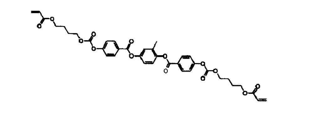
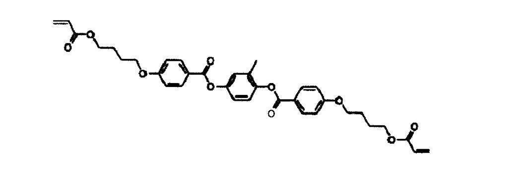

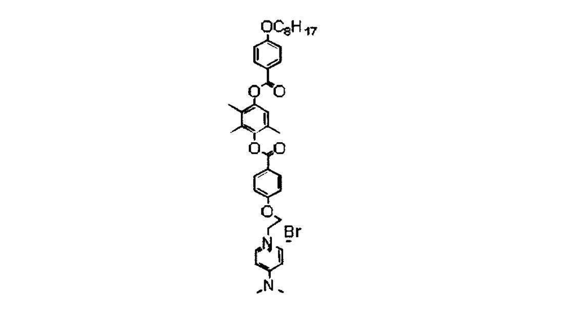

調製した原料液を、図1に示す製造設備のスリットダイに供給し、フィルム上に塗布した。塗布後、乾燥工程にて膜の溶媒を乾燥させ塗膜を形成した。具体的には、55℃温風にて乾燥点に到達するまで乾燥させ、塗膜を形成した。なお乾燥点は、乾燥工程の塗膜温度、及び塗布後の塗膜のない帯状支持体の膜面温度(=塗膜近傍の乾燥風の温度)を測定して、同じ温度になる箇所を見出すことで確認した。ここで、塗膜温度、及び帯状支持体の膜面温度は非接触温度計(IT2―80、キーエンス社製)を設置して測定を行った。その後、塗膜の温度を重合性液晶化合物が再度配向し、かつ配向制御剤及び配向補助剤が固定化する温度まで冷却する冷却工程を経て、紫外線照射前の温度を表に記載された温度にして酸素濃度300ppm雰囲気中で高圧水銀灯により300mJ/cm2の積算光量の紫外線照射を行った。
<配向欠陥の評価>
得られたフィルムをクロスニコル偏光子に挟み、配向欠陥に起因して観察される白濁部の有無を目視にて観察した。
A :白濁部なし
B :若干の白濁部が見えるが、実用上弊害なし
C :白濁部がはっきり見え、実用上弊害あり
<密着性の評価>
JIS K5600-5-6(JIS:Japanese Industrial Standards、JIS K5600―5―6はISO 2409に対応、ISO:International Organization for Standardization)に準拠したクロスカット法により評価を行った。
A :はがれ0%(はがれなし)
B :はがれ5%以内
C :はがれ10%以内
D :はがれ10%より大きい
<評価結果>
図3及び図4の表は、製造条件と評価結果を示している。
Claims (5)
- 可塑剤と光学特性調整剤との少なくとも1つを含む帯状の支持体を準備する工程と、
連続走行する前記支持体の上に、棒状の重合性液晶化合物と配向制御剤と配向補助剤とを、前記支持体を溶解または膨潤する溶媒に溶解させた原料液を塗布して膜を形成する塗布工程と、
前記支持体の上に塗布された膜を乾燥することで、前記配向制御剤と前記配向補助剤の位置を固定し、かつ前記溶媒を前記支持体の内部に0.3μm以上染み込ませた塗膜を形成する乾燥工程と、
前記塗膜の内部温度が前記配向制御剤と前記配向補助剤とを前記塗膜の表面に移動させる温度となるように、前記塗膜を25秒以上加熱する熱処理工程と、
前記熱処理工程後、前記塗膜の内部温度を前記配向制御剤と前記配向補助剤の位置を固定する温度になるよう冷却する冷却工程と、
前記冷却工程後、3質量%未満の残留溶媒比率の前記塗膜に活性放射線を照射して、前記塗膜を硬化し、光学異方性層を形成する硬化工程と、
を含む位相差フィルムの製造方法。 - 前記原料液に含まれる前記溶媒は、前記支持体の素材の溶解度パラメータSP値に対し±2(J/cm3)1/2の範囲内の溶解度パラメータSP値を有する請求項1に記載の位相差フィルムの製造方法。
- 前記原料液は、前記支持体を溶解または膨潤する前記溶媒に加えて、他の複数の溶媒を含む請求項1又は2に記載の位相差フィルムの製造方法。
- 前記乾燥工程において、前記膜を0.1 g/m2・sec以下の乾燥速度で乾燥させる工程を含む請求項1から3のいずれか1項に記載の位相差フィルムの製造方法。
- 前記支持体が、セルロース系フィルムである請求項1から4のいずれか1項に記載の位相差フィルムの製造方法。
Priority Applications (3)
| Application Number | Priority Date | Filing Date | Title |
|---|---|---|---|
| CN201480019223.0A CN105074516A (zh) | 2013-03-29 | 2014-03-20 | 相位差膜的制造方法 |
| JP2015508424A JP6146935B2 (ja) | 2013-03-29 | 2014-03-20 | 位相差フィルムの製造方法 |
| KR1020157026853A KR101745235B1 (ko) | 2013-03-29 | 2014-03-20 | 위상차 필름의 제조 방법 |
Applications Claiming Priority (2)
| Application Number | Priority Date | Filing Date | Title |
|---|---|---|---|
| JP2013-073104 | 2013-03-29 | ||
| JP2013073104 | 2013-03-29 |
Publications (1)
| Publication Number | Publication Date |
|---|---|
| WO2014156981A1 true WO2014156981A1 (ja) | 2014-10-02 |
Family
ID=51623958
Family Applications (1)
| Application Number | Title | Priority Date | Filing Date |
|---|---|---|---|
| PCT/JP2014/057819 Ceased WO2014156981A1 (ja) | 2013-03-29 | 2014-03-20 | 位相差フィルムの製造方法 |
Country Status (4)
| Country | Link |
|---|---|
| JP (1) | JP6146935B2 (ja) |
| KR (1) | KR101745235B1 (ja) |
| CN (1) | CN105074516A (ja) |
| WO (1) | WO2014156981A1 (ja) |
Cited By (5)
| Publication number | Priority date | Publication date | Assignee | Title |
|---|---|---|---|---|
| JP2016206236A (ja) * | 2015-04-15 | 2016-12-08 | 大日本印刷株式会社 | 光学フィルム |
| JP2016206239A (ja) * | 2015-04-15 | 2016-12-08 | 大日本印刷株式会社 | 光学フィルム |
| JPWO2021033639A1 (ja) * | 2019-08-16 | 2021-02-25 | ||
| WO2021167075A1 (ja) * | 2020-02-20 | 2021-08-26 | 富士フイルム株式会社 | 光学積層体、偏光板、画像表示装置 |
| JPWO2022176884A1 (ja) * | 2021-02-16 | 2022-08-25 |
Families Citing this family (1)
| Publication number | Priority date | Publication date | Assignee | Title |
|---|---|---|---|---|
| WO2018030449A1 (ja) | 2016-08-12 | 2018-02-15 | 富士フイルム株式会社 | 光学フィルム、偏光板および画像表示装置 |
Citations (7)
| Publication number | Priority date | Publication date | Assignee | Title |
|---|---|---|---|---|
| JP2003029037A (ja) * | 2001-07-16 | 2003-01-29 | Nitto Denko Corp | 光学フィルムの製造方法 |
| JP2007094208A (ja) * | 2005-09-29 | 2007-04-12 | Dainippon Printing Co Ltd | 位相差フイルム |
| JP2008009345A (ja) * | 2006-06-30 | 2008-01-17 | Dainippon Printing Co Ltd | 位相差フィルム |
| JP2008083511A (ja) * | 2006-09-28 | 2008-04-10 | Dainippon Printing Co Ltd | 液晶組成物、およびこれを用いたカラーフィルタ及び液晶表示装置 |
| JP2008523443A (ja) * | 2004-12-11 | 2008-07-03 | エルジー・ケム・リミテッド | 配向膜の要らないホメオトロピック配向液晶フィルム及びその製造方法 |
| JP2009175650A (ja) * | 2007-12-28 | 2009-08-06 | Konica Minolta Opto Inc | 光学補償フィルムの製造方法、光学補償フィルム、偏光板及び液晶表示装置 |
| JP2010217278A (ja) * | 2009-03-13 | 2010-09-30 | Lintec Corp | 位相差フィルムの製造方法 |
Family Cites Families (5)
| Publication number | Priority date | Publication date | Assignee | Title |
|---|---|---|---|---|
| JP4581274B2 (ja) * | 2001-03-22 | 2010-11-17 | コニカミノルタホールディングス株式会社 | 光学補償フィルムの製造方法 |
| JP2007286330A (ja) * | 2006-04-17 | 2007-11-01 | Fujifilm Corp | 光学補償フィルム、偏光板及び液晶表示装置 |
| JP2009122421A (ja) * | 2007-11-15 | 2009-06-04 | Konica Minolta Opto Inc | 位相差フィルムの製造方法 |
| CN101726785B (zh) * | 2008-10-20 | 2011-10-26 | 财团法人工业技术研究院 | 相位差膜与其形成方法 |
| JP5115500B2 (ja) * | 2009-03-12 | 2013-01-09 | コニカミノルタアドバンストレイヤー株式会社 | 光学補償フィルムの製造方法 |
-
2014
- 2014-03-20 KR KR1020157026853A patent/KR101745235B1/ko active Active
- 2014-03-20 WO PCT/JP2014/057819 patent/WO2014156981A1/ja not_active Ceased
- 2014-03-20 CN CN201480019223.0A patent/CN105074516A/zh active Pending
- 2014-03-20 JP JP2015508424A patent/JP6146935B2/ja active Active
Patent Citations (7)
| Publication number | Priority date | Publication date | Assignee | Title |
|---|---|---|---|---|
| JP2003029037A (ja) * | 2001-07-16 | 2003-01-29 | Nitto Denko Corp | 光学フィルムの製造方法 |
| JP2008523443A (ja) * | 2004-12-11 | 2008-07-03 | エルジー・ケム・リミテッド | 配向膜の要らないホメオトロピック配向液晶フィルム及びその製造方法 |
| JP2007094208A (ja) * | 2005-09-29 | 2007-04-12 | Dainippon Printing Co Ltd | 位相差フイルム |
| JP2008009345A (ja) * | 2006-06-30 | 2008-01-17 | Dainippon Printing Co Ltd | 位相差フィルム |
| JP2008083511A (ja) * | 2006-09-28 | 2008-04-10 | Dainippon Printing Co Ltd | 液晶組成物、およびこれを用いたカラーフィルタ及び液晶表示装置 |
| JP2009175650A (ja) * | 2007-12-28 | 2009-08-06 | Konica Minolta Opto Inc | 光学補償フィルムの製造方法、光学補償フィルム、偏光板及び液晶表示装置 |
| JP2010217278A (ja) * | 2009-03-13 | 2010-09-30 | Lintec Corp | 位相差フィルムの製造方法 |
Cited By (10)
| Publication number | Priority date | Publication date | Assignee | Title |
|---|---|---|---|---|
| JP2016206236A (ja) * | 2015-04-15 | 2016-12-08 | 大日本印刷株式会社 | 光学フィルム |
| JP2016206239A (ja) * | 2015-04-15 | 2016-12-08 | 大日本印刷株式会社 | 光学フィルム |
| JPWO2021033639A1 (ja) * | 2019-08-16 | 2021-02-25 | ||
| WO2021033639A1 (ja) * | 2019-08-16 | 2021-02-25 | 富士フイルム株式会社 | 光学フィルムの製造方法 |
| WO2021167075A1 (ja) * | 2020-02-20 | 2021-08-26 | 富士フイルム株式会社 | 光学積層体、偏光板、画像表示装置 |
| JPWO2021167075A1 (ja) * | 2020-02-20 | 2021-08-26 | ||
| JP7438321B2 (ja) | 2020-02-20 | 2024-02-26 | 富士フイルム株式会社 | 光学積層体、偏光板、画像表示装置 |
| US12360302B2 (en) | 2020-02-20 | 2025-07-15 | Fujifilm Corporation | Optical laminate, polarizing plate, and image display device |
| JPWO2022176884A1 (ja) * | 2021-02-16 | 2022-08-25 | ||
| WO2022176884A1 (ja) * | 2021-02-16 | 2022-08-25 | 富士フイルム株式会社 | 光学フィルムの製造方法 |
Also Published As
| Publication number | Publication date |
|---|---|
| CN105074516A (zh) | 2015-11-18 |
| JP6146935B2 (ja) | 2017-06-14 |
| JPWO2014156981A1 (ja) | 2017-02-16 |
| KR20150119471A (ko) | 2015-10-23 |
| KR101745235B1 (ko) | 2017-06-08 |
Similar Documents
| Publication | Publication Date | Title |
|---|---|---|
| JP6146935B2 (ja) | 位相差フィルムの製造方法 | |
| TWI243264B (en) | Optical compensating sheet and process for producing it, polarizing plate and liquid crystal display device | |
| JP6055917B2 (ja) | 光学フィルム、偏光板、画像表示装置および光学フィルムの製造方法 | |
| US8318043B2 (en) | Composition for liquid crystal film, liquid crystal film using composition, and method of manufacturing liquid crystal film | |
| JP6837415B2 (ja) | 光学フィルムの製造方法および、光学フィルム、光学フィルム積層体、偏光板、画像表示装置 | |
| WO2021060378A1 (ja) | 光学フィルム、円偏光板、有機エレクトロルミネッセンス表示装置 | |
| JP7376600B2 (ja) | 光学フィルム | |
| TW200925672A (en) | Long phase difference film, long elliptic polarization film, elliptic polarization plate and image display device | |
| JP5876801B2 (ja) | 光学フィルム、液晶表示装置、転写材、及び光学フィルムの製造方法 | |
| JP2004046195A (ja) | 光学補償子の製造方法 | |
| WO2021033631A1 (ja) | 光学異方性層の製造方法、積層体の製造方法、偏光子付き光学異方性層の製造方法、偏光子付き積層体の製造方法、組成物、光学異方性層 | |
| JP2002277637A (ja) | 光学補償フィルムの製造方法、光学補償フィルム、偏光板及びそれを用いる液晶ディスプレイ | |
| JP5488258B2 (ja) | 光学補償フィルムの製造方法 | |
| EP3546992A1 (en) | Method for producing optical article and optical article | |
| CN111886527B (zh) | 偏振器、偏振器的制造方法、层叠体及图像显示装置 | |
| JP6045421B2 (ja) | 位相差フィルムの製造方法 | |
| JP2006235611A (ja) | 光学フィルムの製造方法 | |
| JP2004139084A (ja) | 光学補償子 | |
| JP2006098460A (ja) | 位相差フィルム、偏光板、液晶パネル、液晶表示装置及び位相差フィルムの製造方法 | |
| TW201106060A (en) | Liquid crystal display apparatus | |
| WO2019098215A1 (ja) | 長尺液晶フィルム、長尺偏光板、画像表示装置、および、長尺液晶フィルムの製造方法 | |
| JPWO2016002946A1 (ja) | 光学機能性層作製用組成物、光学機能性層を含む光学フィルムの製造方法、および光学フィルム | |
| JP6967083B2 (ja) | 長尺液晶フィルム、長尺偏光板、画像表示装置、および、長尺液晶フィルムの製造方法 | |
| JP2006243025A (ja) | 液晶用配向膜および該配向膜より得られる液晶性光学フィルム | |
| TW200813500A (en) | Optical compensation film and method of producing the same, polarizing plate and liquid crystal display |
Legal Events
| Date | Code | Title | Description |
|---|---|---|---|
| WWE | Wipo information: entry into national phase |
Ref document number: 201480019223.0 Country of ref document: CN |
|
| 121 | Ep: the epo has been informed by wipo that ep was designated in this application |
Ref document number: 14773863 Country of ref document: EP Kind code of ref document: A1 |
|
| ENP | Entry into the national phase |
Ref document number: 2015508424 Country of ref document: JP Kind code of ref document: A |
|
| ENP | Entry into the national phase |
Ref document number: 20157026853 Country of ref document: KR Kind code of ref document: A |
|
| NENP | Non-entry into the national phase |
Ref country code: DE |
|
| 122 | Ep: pct application non-entry in european phase |
Ref document number: 14773863 Country of ref document: EP Kind code of ref document: A1 |