WO2014156975A1 - Dispositif de transmission de puissance - Google Patents
Dispositif de transmission de puissance Download PDFInfo
- Publication number
- WO2014156975A1 WO2014156975A1 PCT/JP2014/057810 JP2014057810W WO2014156975A1 WO 2014156975 A1 WO2014156975 A1 WO 2014156975A1 JP 2014057810 W JP2014057810 W JP 2014057810W WO 2014156975 A1 WO2014156975 A1 WO 2014156975A1
- Authority
- WO
- WIPO (PCT)
- Prior art keywords
- power transmission
- transmission device
- support member
- drum
- brake
- Prior art date
Links
Images


Classifications
-
- F—MECHANICAL ENGINEERING; LIGHTING; HEATING; WEAPONS; BLASTING
- F16—ENGINEERING ELEMENTS AND UNITS; GENERAL MEASURES FOR PRODUCING AND MAINTAINING EFFECTIVE FUNCTIONING OF MACHINES OR INSTALLATIONS; THERMAL INSULATION IN GENERAL
- F16H—GEARING
- F16H57/00—General details of gearing
- F16H57/08—General details of gearing of gearings with members having orbital motion
- F16H57/10—Braking arrangements
-
- F—MECHANICAL ENGINEERING; LIGHTING; HEATING; WEAPONS; BLASTING
- F16—ENGINEERING ELEMENTS AND UNITS; GENERAL MEASURES FOR PRODUCING AND MAINTAINING EFFECTIVE FUNCTIONING OF MACHINES OR INSTALLATIONS; THERMAL INSULATION IN GENERAL
- F16H—GEARING
- F16H57/00—General details of gearing
- F16H57/02—Gearboxes; Mounting gearing therein
- F16H57/021—Shaft support structures, e.g. partition walls, bearing eyes, casing walls or covers with bearings
-
- F—MECHANICAL ENGINEERING; LIGHTING; HEATING; WEAPONS; BLASTING
- F16—ENGINEERING ELEMENTS AND UNITS; GENERAL MEASURES FOR PRODUCING AND MAINTAINING EFFECTIVE FUNCTIONING OF MACHINES OR INSTALLATIONS; THERMAL INSULATION IN GENERAL
- F16H—GEARING
- F16H2200/00—Transmissions for multiple ratios
- F16H2200/003—Transmissions for multiple ratios characterised by the number of forward speeds
- F16H2200/006—Transmissions for multiple ratios characterised by the number of forward speeds the gear ratios comprising eight forward speeds
-
- F—MECHANICAL ENGINEERING; LIGHTING; HEATING; WEAPONS; BLASTING
- F16—ENGINEERING ELEMENTS AND UNITS; GENERAL MEASURES FOR PRODUCING AND MAINTAINING EFFECTIVE FUNCTIONING OF MACHINES OR INSTALLATIONS; THERMAL INSULATION IN GENERAL
- F16H—GEARING
- F16H2200/00—Transmissions for multiple ratios
- F16H2200/20—Transmissions using gears with orbital motion
- F16H2200/2002—Transmissions using gears with orbital motion characterised by the number of sets of orbital gears
- F16H2200/2007—Transmissions using gears with orbital motion characterised by the number of sets of orbital gears with two sets of orbital gears
-
- F—MECHANICAL ENGINEERING; LIGHTING; HEATING; WEAPONS; BLASTING
- F16—ENGINEERING ELEMENTS AND UNITS; GENERAL MEASURES FOR PRODUCING AND MAINTAINING EFFECTIVE FUNCTIONING OF MACHINES OR INSTALLATIONS; THERMAL INSULATION IN GENERAL
- F16H—GEARING
- F16H2200/00—Transmissions for multiple ratios
- F16H2200/20—Transmissions using gears with orbital motion
- F16H2200/202—Transmissions using gears with orbital motion characterised by the type of Ravigneaux set
- F16H2200/2023—Transmissions using gears with orbital motion characterised by the type of Ravigneaux set using a Ravigneaux set with 4 connections
-
- F—MECHANICAL ENGINEERING; LIGHTING; HEATING; WEAPONS; BLASTING
- F16—ENGINEERING ELEMENTS AND UNITS; GENERAL MEASURES FOR PRODUCING AND MAINTAINING EFFECTIVE FUNCTIONING OF MACHINES OR INSTALLATIONS; THERMAL INSULATION IN GENERAL
- F16H—GEARING
- F16H2200/00—Transmissions for multiple ratios
- F16H2200/20—Transmissions using gears with orbital motion
- F16H2200/203—Transmissions using gears with orbital motion characterised by the engaging friction means not of the freewheel type, e.g. friction clutches or brakes
- F16H2200/2046—Transmissions using gears with orbital motion characterised by the engaging friction means not of the freewheel type, e.g. friction clutches or brakes with six engaging means
-
- F—MECHANICAL ENGINEERING; LIGHTING; HEATING; WEAPONS; BLASTING
- F16—ENGINEERING ELEMENTS AND UNITS; GENERAL MEASURES FOR PRODUCING AND MAINTAINING EFFECTIVE FUNCTIONING OF MACHINES OR INSTALLATIONS; THERMAL INSULATION IN GENERAL
- F16H—GEARING
- F16H2200/00—Transmissions for multiple ratios
- F16H2200/20—Transmissions using gears with orbital motion
- F16H2200/203—Transmissions using gears with orbital motion characterised by the engaging friction means not of the freewheel type, e.g. friction clutches or brakes
- F16H2200/2066—Transmissions using gears with orbital motion characterised by the engaging friction means not of the freewheel type, e.g. friction clutches or brakes using one freewheel mechanism
-
- F—MECHANICAL ENGINEERING; LIGHTING; HEATING; WEAPONS; BLASTING
- F16—ENGINEERING ELEMENTS AND UNITS; GENERAL MEASURES FOR PRODUCING AND MAINTAINING EFFECTIVE FUNCTIONING OF MACHINES OR INSTALLATIONS; THERMAL INSULATION IN GENERAL
- F16H—GEARING
- F16H2200/00—Transmissions for multiple ratios
- F16H2200/20—Transmissions using gears with orbital motion
- F16H2200/2079—Transmissions using gears with orbital motion using freewheel type mechanisms, e.g. freewheel clutches
- F16H2200/2082—Transmissions using gears with orbital motion using freewheel type mechanisms, e.g. freewheel clutches one freewheel mechanisms
-
- F—MECHANICAL ENGINEERING; LIGHTING; HEATING; WEAPONS; BLASTING
- F16—ENGINEERING ELEMENTS AND UNITS; GENERAL MEASURES FOR PRODUCING AND MAINTAINING EFFECTIVE FUNCTIONING OF MACHINES OR INSTALLATIONS; THERMAL INSULATION IN GENERAL
- F16H—GEARING
- F16H2200/00—Transmissions for multiple ratios
- F16H2200/20—Transmissions using gears with orbital motion
- F16H2200/2097—Transmissions using gears with orbital motion comprising an orbital gear set member permanently connected to the housing, e.g. a sun wheel permanently connected to the housing
-
- F—MECHANICAL ENGINEERING; LIGHTING; HEATING; WEAPONS; BLASTING
- F16—ENGINEERING ELEMENTS AND UNITS; GENERAL MEASURES FOR PRODUCING AND MAINTAINING EFFECTIVE FUNCTIONING OF MACHINES OR INSTALLATIONS; THERMAL INSULATION IN GENERAL
- F16H—GEARING
- F16H3/00—Toothed gearings for conveying rotary motion with variable gear ratio or for reversing rotary motion
- F16H3/44—Toothed gearings for conveying rotary motion with variable gear ratio or for reversing rotary motion using gears having orbital motion
- F16H3/62—Gearings having three or more central gears
- F16H3/66—Gearings having three or more central gears composed of a number of gear trains without drive passing from one train to another
- F16H3/663—Gearings having three or more central gears composed of a number of gear trains without drive passing from one train to another with conveying rotary motion between axially spaced orbital gears, e.g. RAVIGNEAUX
-
- Y—GENERAL TAGGING OF NEW TECHNOLOGICAL DEVELOPMENTS; GENERAL TAGGING OF CROSS-SECTIONAL TECHNOLOGIES SPANNING OVER SEVERAL SECTIONS OF THE IPC; TECHNICAL SUBJECTS COVERED BY FORMER USPC CROSS-REFERENCE ART COLLECTIONS [XRACs] AND DIGESTS
- Y10—TECHNICAL SUBJECTS COVERED BY FORMER USPC
- Y10T—TECHNICAL SUBJECTS COVERED BY FORMER US CLASSIFICATION
- Y10T74/00—Machine element or mechanism
- Y10T74/19—Gearing
- Y10T74/19637—Gearing with brake means for gearing
Definitions
- the present invention relates to a power transmission device including a transmission, a case for housing the transmission, and a counter drive gear to which power from the transmission is transmitted.
- a transmission mechanism having a multi-plate friction brake that can fix a sun gear of a reduction planetary gear to a transmission case in a non-rotatable manner, a counter drive gear to which power from the transmission mechanism is transmitted, A counter driven gear meshing with the counter drive gear, a drive pinion gear integrated with a counter shaft spline-fitted to the counter driven gear, and a center fastened to the transmission case by a bolt and rotatably supporting the counter drive gear
- a device provided with a support is known (for example, see Patent Document 1).
- the brake drum constituting the brake of the power transmission device has a radial flange portion extending from one end in the inner diameter direction.
- Inner peripheral teeth are formed on the inner peripheral portion of the radial flange portion, and the brake drum rotates to the center support by fitting the inner peripheral teeth with the protrusion formed on the wall surface of the outer peripheral portion of the center support.
- the center support includes a boss portion that rotatably supports the counter drive gear via a bearing, and a wall portion that extends radially outward from the boss portion and is fastened to the transmission case by a bolt.
- a cutout portion is formed in the wall portion of the center support in order to avoid interference with the counter driven gear.
- the main object of the present invention is to improve the strength of the support member that supports the counter drive gear of the power transmission device.
- the power transmission device employs the following means in order to achieve the main object.
- the power transmission device includes: In a power transmission device including a transmission, a case housing the transmission, a counter drive gear to which power from the transmission is transmitted, and a counter driven gear meshing with the counter drive gear, A brake for fixing any rotation element of the transmission to the case in a non-rotatable manner; A fixing member fixed to the case via a fastening member, and a support member that rotatably supports the counter drive gear; A cylindrical drum portion that functions as a brake drum of the brake is formed integrally with the support member.
- a brake drum for a brake that is fixed to a case via a fastening member and rotatably supports a counter drive gear, and any rotation element of the transmission is non-rotatably fixed to the case.
- a functioning cylindrical drum is integrally formed.
- the drum portion also functions as a rib, so that the strength of the support member can be improved.
- Gear noise can be reduced by properly meshing the counter drive gear and the counter driven gear.
- the drum portion integrally with the support member, it is possible to reduce the number of parts and improve the assembly of the transmission and thus the power transmission device.
- the brake is disposed on the inside of the drum portion and connected to the rotating element, a first friction engagement plate fitted to the brake hub, and a drum portion of the support member. It may have a second friction plate to be fitted, and a piston that is disposed inside the drum portion and that frictionally engages the first and second friction engagement plates by pressing,
- the support member includes a boss portion that rotatably supports the counter drive gear, and an annular wall portion that is formed integrally with the boss portion and the drum portion so as to extend between the boss portion and the drum portion. May be.
- a brake oil chamber is defined inside the drum portion.
- the drum portion may include a fastening portion that extends outward from an outer peripheral surface on one end side and is fastened to the case via a bolt, and the outer peripheral surface of the drum portion includes A recess extending from the fastening portion to the other end of the drum portion may be formed, and an inner peripheral surface of the drum portion may be formed with a spline to which the second friction plate is fitted, The spline may have a missing tooth portion formed so as to be positioned on the back side of the recess.
- the depression formed in the outer peripheral surface of the drum portion can be used as a relief portion for a tool or the like, so that the support member can be suppressed from overhanging the fastening portion from the outer peripheral surface of the drum portion.
- the transmission can be made more compact.
- the drum portion and thus the strength of the support member can be kept good even if the recess is formed on the outer peripheral surface.
- the brake further includes a return spring disposed inside the drum portion and biasing the piston, and a spring support member disposed inside the drum portion and supporting the return spring.
- the spring support member may include an annular support portion that supports one end of the return spring, and free end portions that extend from the annular support portion in the circumferential direction and extend inward.
- a plurality of abutting portions may be formed on the inner surface of the annular wall portion, and a plurality of abutting portions that abut against the free end portion of the spring support member may be formed,
- the spring support members are snap rings attached to the annular wall portion so as to support the free end portions that are in contact with the corresponding contact portions. Ri may be retained against the annular wall portion.
- the counter driven gear may be formed so as to be opposed to the support member in the axial direction and may have a tooth portion engageable with another member, and the annular wall portion may include the tooth portion. While having a recessed part formed so that it may surround, the oil chamber to which hydraulic oil is supplied with the drum part and the piston may be defined inside the recessed part.
- the brake oil chamber is defined inside the concave portion of the wall portion, so that a notch (opening) is not formed around the concave portion of the annular wall portion.
- the inner surface of the annular wall portion that defines the oil chamber facing the piston may be formed such that a portion located inside the concave portion protrudes toward the piston side than the other portion.
- a hydraulic oil supply / discharge hole communicating with the oil chamber may be formed so as to be separated from the concave portion in the circumferential direction.
- the portion located inside the recess of the oil chamber is made shorter (shallow) in the axial direction of the piston than other portions to reduce the volume, thereby improving the strength of the annular wall portion and thus the support member.
- the hydraulic oil can be easily returned from the portion located inside the concave portion to the hydraulic oil supply / discharge hole separated from the concave portion, thereby improving the hydraulic oil discharge performance.
- the support member includes a boss portion that rotatably supports the counter drive gear, and an annular wall portion that is integrally formed with the boss portion and the drum portion so as to extend between the boss portion and the drum portion.
- the drum portion may extend to the opposite side of the boss portion in the axial direction.
- the drum portion may extend to the opposite side of the brake in the axial direction so as to surround at least a part of the boss portion, and extend outward from the outer peripheral surface of the boss portion side. You may have a fastening part fastened by the said case via a volt
- FIG. 2 is an operation table showing a relationship between each shift stage of the automatic transmission included in the power transmission device of FIG. 1 and operation states of clutches and brakes.
- FIG. 2 is a velocity diagram illustrating the relationship of the number of rotations between rotating elements constituting an automatic transmission included in the power transmission device of FIG. 1.
- FIG. 2 is an enlarged partial cross-sectional view showing a main part of the power transmission device of FIG. 1. It is a perspective view which shows the supporting member contained in the power transmission device of FIG. It is a perspective view which shows the supporting member contained in the power transmission device of FIG. It is explanatory drawing which shows the structure of the power transmission device of FIG. It is sectional drawing which shows the spring support member contained in the power transmission device of FIG.
- FIG. 1 is a schematic configuration diagram of a power transmission device 20 according to an embodiment of the present invention.
- a power transmission device 20 shown in the figure is connected to a crankshaft of an engine (not shown) mounted on a front wheel drive vehicle and can transmit power from the engine to left and right drive wheels (front wheels) (not shown).
- the power transmission device 20 includes a transmission case 22, a starting device (fluid transmission device) 23 housed in the transmission case 22, an oil pump 24, an automatic transmission 25, and a gear mechanism (gear train). 40, a differential gear (differential mechanism) 50 and the like.
- the starting device 23 included in the power transmission device 20 includes an input-side pump impeller 23p connected to an engine crankshaft and an output-side turbine runner 23t connected to an input shaft (input member) 26 of an automatic transmission 25. , A stator 23s disposed inside the pump impeller 23p and the turbine runner 23t to rectify the flow of hydraulic oil from the turbine runner 23t to the pump impeller 23p, a one-way clutch 23o that restricts the rotational direction of the stator 23s in one direction, and lock-up
- the torque converter includes a clutch 23c, a damper mechanism 23d, and the like.
- the starting device 23 may be configured as a fluid coupling that does not include the stator 23s.
- the oil pump 24 is a gear pump having a pump assembly including a pump body and a pump cover, an external gear connected to the pump impeller 23p of the starting device 23 via a hub, an internal gear that meshes with the external gear, and the like. It is configured.
- the oil pump 24 is driven by power from the engine and sucks hydraulic oil (ATF) stored in an oil pan (not shown) to generate a hydraulic pressure required by the starting device 23 and the automatic transmission 25 (not shown). Pump to control unit.
- ATF hydraulic oil
- the automatic transmission 25 is configured as an 8-speed transmission, and as shown in FIG. 1, in addition to the input shaft 26, a double pinion type first planetary gear mechanism 30 and a Ravigneaux type second planetary gear.
- the gear mechanism 35 includes four clutches C1, C2, C3 and C4 for changing the power transmission path from the input side to the output side, two brakes B1 and B2, and a one-way clutch F1.
- the first planetary gear mechanism 30 of the automatic transmission 25 is engaged with a sun gear 31 that is an external gear and a ring gear 32 that is an internal gear disposed concentrically with the sun gear 31 and one of the first gear mechanism 30 and the sun gear 31.
- the other has a planetary carrier 34 that holds a plurality of sets of two pinion gears 33a and 33b meshing with the ring gear 32 so as to be rotatable (rotatable) and revolved.
- the sun gear 31 of the first planetary gear mechanism 30 is fixed to the transmission case 22, and the planetary carrier 34 of the first planetary gear mechanism 30 is coupled to the input shaft 26 so as to be integrally rotatable.
- the first planetary gear mechanism 30 is configured as a so-called reduction gear, and decelerates the power transmitted to the planetary carrier 34 as an input element and outputs it from a ring gear 32 as an output element.
- the second planetary gear mechanism 35 of the automatic transmission 25 is an internal gear disposed concentrically with the first sun gear 36a and the second sun gear 36b, which are external gears, and the first and second sun gears 36a and 36b.
- the ring gear 37 of the second planetary gear mechanism 35 functions as an output member of the automatic transmission 25, and the power transmitted from the input shaft 26 to the ring gear 37 is transmitted to the left and right via the gear mechanism 40, the differential gear 50 and the drive shaft 51. Is transmitted to the driving wheel.
- the planetary carrier 39 is supported by the transmission case 22 via the one-way clutch F1, and the rotation direction of the planetary carrier 39 is limited to one direction by the one-way clutch F1.
- the clutch C1 has a hydraulic servo including a piston, a plurality of friction plates and separator plates, an oil chamber to which hydraulic oil is supplied, and the like.
- the ring gear 32 of the first planetary gear mechanism 30 and the second planetary gear mechanism 35 This is a multi-plate friction type hydraulic clutch (friction engagement element) capable of fastening the first sun gear 36a and releasing the fastening of both.
- the clutch C2 has a hydraulic servo including a piston, a plurality of friction plates and separator plates, an oil chamber to which hydraulic oil is supplied, and the like, and the input shaft 26 and the planetary carrier 39 of the second planetary gear mechanism 35 are fastened.
- this is a multi-plate friction type hydraulic clutch capable of releasing the fastening of both.
- the clutch C3 has a hydraulic servo including a piston, a plurality of friction plates and separator plates, an oil chamber to which hydraulic oil is supplied, and the like.
- the ring gear 32 of the first planetary gear mechanism 30 and the second planetary gear mechanism 35 This is a multi-plate friction hydraulic clutch capable of fastening the second sun gear 36b and releasing the fastening of both.
- the clutch C4 has a hydraulic servo including a piston, a plurality of friction plates and separator plates, an oil chamber to which hydraulic oil is supplied, and the like.
- the planetary carrier 34 and the second planetary gear mechanism 35 of the first planetary gear mechanism 30 are provided. This is a multi-plate friction type hydraulic clutch capable of fastening the second sun gear 36b and releasing the fastening of both.
- the brake B1 has a hydraulic servo including a plurality of friction plates, separator plates, an oil chamber to which hydraulic oil is supplied, and the like, so that the second sun gear 36b of the second planetary gear mechanism 35 cannot be rotated to the transmission case 22.
- This is a multi-plate friction type hydraulic brake that can be fixed and can release the fixing of the second sun gear 36b to the transmission case 22.
- the brake B2 has a hydraulic servo including a plurality of friction plates, separator plates, an oil chamber to which hydraulic oil is supplied, and the planetary carrier 39 of the second planetary gear mechanism 35 is fixed to the transmission case 22 so as not to rotate.
- This is a multi-plate friction type hydraulic brake that can release the fixation of the planetary carrier 39 to the transmission case 22.
- the one-way clutch F1 includes an inner race coupled to (fixed to) the planetary carrier 39 of the second planetary gear mechanism 35, an outer race, a plurality of sprags, a plurality of springs (plate springs), a cage, and the like.
- the outer race rotates in one direction with respect to the race, torque is transmitted through each sprag, and when the outer race rotates in the other direction with respect to the inner race, both are rotated relative to each other.
- the one-way clutch F1 may have a configuration other than a sprag type such as a roller type.
- FIG. 2 shows an operation table showing the relationship between the respective speeds of the automatic transmission 25 and the operating states of the clutches C1 to C4, the brakes B1 and B2, and the one-way clutch F1, and FIG.
- the speed diagram which illustrates the relationship of the rotation speed between rotation elements is shown.
- the automatic transmission 25 provides forward 1st to 8th gears and reverse 1st and 2nd gears by setting the clutches C1 to C4 and the brakes B1 and B2 to the states shown in the operation table of FIG. .
- at least one of the clutches C1 to C4 and the brakes B1 and B2 may be a meshing engagement element such as a dog clutch.
- the gear mechanism 40 is fixed to a counter drive gear 41 connected to the ring gear 37 of the second planetary gear mechanism 35 of the automatic transmission 25 and a counter shaft 42 extending in parallel with the input shaft 26 of the automatic transmission 25.
- a counter driven gear 43 that meshes with the counter drive gear 41, a drive pinion gear (final drive gear) 44 that is integrally formed (or fixed) on the counter shaft 42 so as to be spaced apart from the counter driven gear 43 in the axial direction, and a drive pinion gear 44 and a differential ring gear (final driven gear) 45 coupled to the differential gear 50.
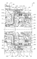
- FIG. 4 is an enlarged partial cross-sectional view showing a main part of the power transmission device 20.
- This figure shows the configuration around the counter drive gear 41 and the brake B1 of the gear mechanism 40 included in the power transmission device 20.
- the counter drive gear 41 of the gear mechanism 40 is connected to the ring gear 37 of the second planetary gear mechanism 35 and is supported by a support member (center support) 100 that is fixed to the case via a plurality of bolts 99. It is supported rotatably.
- the support member 100 includes, for example, a boss portion 101 that rotatably supports the counter drive gear via a bearing 90 that is a taper roller bearing or a ball bearing, and a substantially disc-like shape that extends outward from one end of the boss portion 101.
- An annular wall portion 102 and a cylindrical drum portion 110 extending from the annular wall portion 102 are included.
- the boss portion 101, the annular wall portion 102, and the drum portion 110 are integrally formed by casting, for example, an aluminum alloy.
- the boss 101 of the support member 100 is formed in a cylindrical shape, and the inner race of the bearing 90 is fixed to the outer peripheral surface thereof.
- the outer race of the bearing 90 is fixed to the inner peripheral surface of the counter drive gear 41 formed in an annular shape, whereby the counter drive gear 41 is rotatably supported by the boss portion 101.
- the annular wall portion 102 of the support member 100 extends radially outward from the end portion (right end portion in FIG. 4) of the boss portion 101 on the first planetary gear mechanism 30 side. Extending between the boss portion 101 and the drum portion 110.
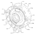
- the drum portion 110 extends in the axial direction of the input shaft 26 from the outer peripheral portion of the annular wall portion 102 toward the first planetary gear mechanism 30 side (the right side in FIG. 4) and surrounds the boss portion 101. It extends from the outer peripheral part of the part 102 toward the opposite side to the first planetary gear mechanism 30 (second planetary gear mechanism 35 side: left side in FIG. 4). As shown in FIGS. 5 and 6, the drum portion 110 has a cylindrical outer peripheral surface 110 s. And from the outer peripheral surface 110s of the edge part (left end part in FIG.
- the some fastening part 111 which has the bolt hole 111a in which the above-mentioned volt
- the plurality of fastening portions 111 are formed integrally with the drum portion 110 so as not to interfere with the counter driven gear 43 that meshes with the counter drive gear 41 supported by the boss portion 101.
- a recess 112 is formed on the outer peripheral surface 110s of the drum part 110 so as to extend from each fastening part 111 to an open end part (right end part in FIG. 4) of the drum part 110 on the first planetary gear mechanism 30 side.
- the drum portion 110 of the support member 100 configured as described above functions as a brake drum of the brake B1 that fixes the second sun gear 36b of the second planetary gear mechanism 35 to the transmission case 22 in a non-rotatable manner.
- the cylindrical drum portion 110 is integrally formed with the support member 100 that supports the counter drive gear 41, so that the drum portion 110 also functions as a rib, so that the strength of the support member 100 is improved. It becomes possible to make it.
- the support member 100 is prevented from being deformed even if a load from the counter driven gear 43 side acts on the support member 100. Therefore, the gear noise can be reduced by properly meshing the counter drive gear 41 and the counter driven gear 43.
- the drum portion 110 by integrally forming the drum portion 110 on the support member 100, the number of parts can be reduced, and the assembly of the automatic transmission 25 and hence the power transmission device 20 can be improved.
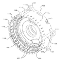
- a plurality of ribs 113 are formed to extend radially between the inner peripheral surface of the portion surrounding the boss portion 101 of the drum portion 110 and the annular wall portion 102. Thereby, the strength of the support member 100 can be further improved.
- the support member 100 inserts the bolt 99 into the bolt hole 111 a of each fastening portion 111 and screwes each bolt 99 into the screw hole formed in the transmission case 22.
- the portion 110 is fixed to the transmission case 22 between the counter driven gear 43 and the drive pinion gear 44 so as to be closer to the axis of the counter shaft 42 (the counter driven gear 43 and the drive pinion gear 44) than the tooth tip 44t of the drive pinion gear 44. Is done. That is, the outer peripheral surface 110 s of the drum portion 110 is closer to the axis of the counter shaft 42 than the tooth tip 44 t of the drive pinion gear 44 between the counter driven gear 43 and the drive pinion gear 44.
- the power transmission device 20 including the automatic transmission 25 it is possible to suppress the increase in the inter-axis distance between the counter drive gear 41 and the counter driven gear 43, that is, the counter shaft 42, and to reduce the size of the entire device.
- the recess 112 formed in the outer peripheral surface 110s of the drum portion 110 when the support member 100 is fastened to the transmission case 22 can be used as a relief portion (escape groove) for a tool or the like.
- the overhang of the fastening portion 111 from the outer peripheral surface 110s can be suppressed and the support member 100 and thus the automatic transmission 25 can be made more compact.
- a recess 103 is formed in the annular wall portion 102 of the support member so as to surround a part of the counter driven gear 43 that meshes with the counter drive gear 41. That is, the counter driven gear 43 is formed with a parking gear (tooth portion) 43p that can mesh with a parking pole (other member) (not shown) so as to face the support member 100 in the axial direction. It has an inner peripheral surface 103a extending in a substantially arc shape surrounding a part of the parking gear portion 43p of the driven gear 43, and a flat side end surface 103b facing the side portion of the parking gear portion 43p (see FIG. 5).
- the parking gear is suppressed while suppressing interference between the support member 100 and the counter driven gear 43 (parking gear portion 43p).
- the power transmission device 20 as a whole can be made compact by bringing them close together so that the portion 43p enters the recess 103.
- the brake B1 that uses the drum portion 110 of the support member 100 as a brake drum is fitted to the brake hub 120 and the brake hub 120 so as to be movably supported by the brake hub 120, as shown in FIG.
- the brake hub 120 is connected to the second sun gear 36b of the second planetary gear mechanism 35 and a clutch drum shared by the clutches C3 and C4, and can rotate integrally with the second sun gear 36b and the clutch drum.
- On the outer peripheral surface of the hub 120 splines that can be engaged with the concavo-convex portions formed on the inner peripheral portion of each friction plate 121 are formed.
- the friction plate 121 is an annular member having a friction material attached to both surfaces.
- the separator plate 122 is an annular member having both surfaces formed smoothly, and is fitted to the spline 115 of the drum portion 110 so as to be alternately arranged with the plurality of friction plates 121 fitted to the brake hub 120.
- the backing plate 123 is fitted to the spline 115 of the drum portion 110 so as to be able to come into contact with the friction plate 121 arranged on the rightmost side (the first planetary gear mechanism 30 side) in FIG. It is supported in the axial direction by a snap ring attached to.
- the spline 115 of the drum portion 110 has a missing tooth portion 116 formed so as to be positioned behind the recess 112 of the outer peripheral surface 110s by thinning out the spline teeth.
- the brake B ⁇ b> 1 is disposed inside the drum portion 110, and is disposed inside the drum portion 110 and a piston 125 that presses the friction plate 121 and the separator plate 122 to frictionally engage them.
- a plurality of return springs (coil springs) 126 that urge the piston 125 and a spring support member 127 that is disposed inside the drum portion 110 and supports the plurality of return springs 126.
- the piston 125 is movably supported by the support member 100 so as to be positioned closer to the annular wall portion 102 than the friction plate 121 and the separator plate 122.
- the cylindrical piston support portion 105 extends in the axial direction of the input shaft 26 so as to be located inside the drum portion 110 at a position relatively close to the drum portion 110.
- the piston 125 is movably supported by the inner peripheral surface of the drum portion 110 and the outer peripheral surface of the piston support portion 105, and between the outer peripheral portion of the piston 125 and the inner peripheral surface of the drum portion 110 and within the piston 125. Seal members are respectively disposed between the peripheral portion and the outer peripheral surface of the piston support portion 105.
- an engagement oil chamber 130 to which hydraulic oil for engaging the brake B1 is supplied is defined by the piston 125, the drum portion 110, and the annular wall portion 102 including the piston support portion 105.
- the engagement oil chamber 130 is defined so as to be located inside the drum portion 110 and inside the concave portion 103 of the annular wall portion 102.
- the engagement oil chamber 130 of the brake B1 is defined inside the concave portion 103 of the annular wall portion 102, so that a notch (opening) is formed around the concave portion 103 of the annular wall portion 102 to prevent leakage of hydraulic oil. ) Is not formed, it is possible to suppress a decrease in the strength of the support member 100 associated with the formation of the recess 103 as described above.
- the inner wall of the annular wall 102 that faces the piston 125 and defines the engagement oil chamber 130 is such that a portion located inside the recess 103 protrudes closer to the piston 125 than other portions. Formed as follows. That is, as shown in FIGS. 4 and 7, the inner surface 105 b of the annular wall portion 102 positioned inside the recess 103 is more piston 125 than the other inner surface 105 a of the annular wall portion 102 that defines the engagement oil chamber 130. Protrudes to the side. As shown in FIG. 7, the support member 100 communicates with the engagement oil chamber 130 to supply hydraulic oil from the hydraulic control device (not shown) to the engagement oil chamber 130 and from the engagement oil chamber 130.
- a hydraulic oil supply / discharge hole 117 that allows hydraulic oil to be discharged is formed at a position that is substantially symmetrical with the concave portion 103 with respect to the axis of the input shaft 26 so as to be spaced apart from the concave portion 103 in the circumferential direction.
- the portion located inside the recess 103 of the engagement oil chamber 130 is made shorter (shallow) in the axial direction of the piston 125 than the other portions to reduce the volume, thereby reducing the annular wall portion 102 and the support member.
- the hydraulic oil can be easily returned from the portion located inside the concave portion 103 to the hydraulic oil supply / discharge hole 117 separated from the concave portion 103, and the discharge performance of the hydraulic oil can be improved.
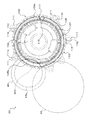
- FIG. 8 is a cross-sectional view showing a spring support member 127 that supports a plurality of return springs 126 that urge the piston 125.
- the spring support member 127 includes an annular support portion 127a having a plurality of engagement portions 127e fitted to one ends of the corresponding return springs 126, and a circumferential interval from the annular support portion 127a.
- a plurality of extending portions 127b including a substantially rectangular free end portion 127f that extends toward the annular wall portion 102 and extends radially inward.
- a plurality of contact recesses (each contacting with the free end portion 127 f of the spring support member 127).
- (Contact portion) 107 is formed.
- the plurality of contact recesses 107 are formed at equal intervals on the inner surface of the annular wall portion 102 excluding the inner side of the recess 103, and correspondingly, the spring support member 127 has The same number of extending portions 127b as the number of the contact concave portions 107 of the annular wall portion 102 are extended from the annular support portion 127a.
- the spring support member 127 is disposed with respect to the annular wall portion 102 so that the outer surface of each extending portion 127 b contacts the inner peripheral surface of the piston support portion 105. It is prevented from coming off from the annular wall 102 by a snap ring 128 attached to the annular wall 102 so as to support the free end 127f in contact with the contact recess 107.
- the spring support member 127 can be disposed in a narrow space in the drum portion 110, and the space required to support the plurality of return springs 126 can be reduced to reduce the automatic transmission 25 and thus the power transmission device 20. It can be made more compact.
- a single leaf spring may be used instead of a plurality of coil springs.
- the second sun gear 36 b of the second planetary gear mechanism 35 is fixed to the support member 100 that is fixed to the transmission case 22 via the bolt 99 and rotatably supports the counter drive gear 41.
- the cylindrical drum portion 110 is integrally formed with the support member 100 that supports the counter drive gear 41, so that the drum portion 110 also functions as a rib, so that the strength of the support member 100 is improved. It becomes possible to make it. As a result, even if a load from the counter driven gear 43 is applied to the support member 100, the support member 100 can be prevented from being deformed, so that the counter drive gear 41 and the counter driven gear 43 are properly meshed with each other. Gear noise can be reduced. Furthermore, by integrally forming the drum portion 110 on the support member 100, the number of parts can be reduced, and the assembly of the automatic transmission 25 and hence the power transmission device 20 can be improved.
- the annular wall portion 102 of the support member 100 is formed in a disk shape without having a notch (opening), a decrease in strength of the support member 100 can be suppressed.
- the engagement oil chamber 130 of the brake B1 is defined inside the drum portion 110 that is integrally formed with the support member 100, so that the brake B1 and thus the automatic transmission 25 can be made compact.
- a recess 112 extending from the fastening portion 111 to the open end of the drum portion 110 is formed on the outer peripheral surface 110 s of the drum portion 110, and a spline formed on the inner peripheral surface of the drum portion 110.
- Reference numeral 115 has a missing tooth portion 116 formed so as to be located on the back side of the recess 112. Accordingly, when the support member 100 is fastened to the transmission case 22, the recess 112 formed on the outer peripheral surface of the drum portion 110 can be used as a relief portion for a tool or the like. Therefore, the fastening portion from the outer peripheral surface 110 s of the drum portion 110.
- the spring support member 127 of the power transmission device 20 includes an annular support portion 127a that supports one end of the return spring 126, and an idler extending from the annular support portion 127a at intervals in the circumferential direction and extending inward.
- the ring 128 prevents the annular wall portion 102 from coming off.
- the spring support member 127 can be disposed in a narrow space in the drum portion 110, and the space required to support the return spring 126 is reduced, and the automatic transmission 25 and thus the power transmission device 20 are made more compact.
- the strength of the support member 100 is reduced.
- the engagement oil chamber 130 of the brake B1 is defined inside the drum portion 110 and inside the concave portion 103 of the annular wall portion 102, so that a notch is formed around the concave portion 103 of the annular wall portion 102 ( Opening) will not be formed.
- the strength of the support member 100 can be satisfactorily reduced due to the formation of the recess 103 for suppressing interference with the parking gear 43p.
- the portion located inside the recess 103 of the engagement oil chamber 130 is shortened (shallow) in the axial direction of the piston 125 so that the volume is reduced compared to other portions. .
- the hydraulic oil can be easily returned from the portion located inside the concave portion 103 to the hydraulic oil supply / discharge hole 117 spaced apart from the portion. Emission can be improved.
- the present invention can be used in the power transmission device manufacturing industry and the like.
Landscapes
- Engineering & Computer Science (AREA)
- General Engineering & Computer Science (AREA)
- Mechanical Engineering (AREA)
- General Details Of Gearings (AREA)
- Structure Of Transmissions (AREA)
Abstract
Priority Applications (4)
| Application Number | Priority Date | Filing Date | Title |
|---|---|---|---|
| CN201480012682.6A CN105026796B (zh) | 2013-03-29 | 2014-03-20 | 动力传递装置 |
| US14/764,925 US9958056B2 (en) | 2013-03-29 | 2014-03-20 | Power transmission apparatus |
| KR1020157024183A KR101810756B1 (ko) | 2013-03-29 | 2014-03-20 | 동력 전달 장치 |
| EP14774694.5A EP2937600B1 (fr) | 2013-03-29 | 2014-03-20 | Dispositif de transmission de puissance |
Applications Claiming Priority (2)
| Application Number | Priority Date | Filing Date | Title |
|---|---|---|---|
| JP2013073678A JP6119378B2 (ja) | 2013-03-29 | 2013-03-29 | 動力伝達装置 |
| JP2013-073678 | 2013-03-29 |
Publications (1)
| Publication Number | Publication Date |
|---|---|
| WO2014156975A1 true WO2014156975A1 (fr) | 2014-10-02 |
Family
ID=51623952
Family Applications (1)
| Application Number | Title | Priority Date | Filing Date |
|---|---|---|---|
| PCT/JP2014/057810 WO2014156975A1 (fr) | 2013-03-29 | 2014-03-20 | Dispositif de transmission de puissance |
Country Status (6)
| Country | Link |
|---|---|
| US (1) | US9958056B2 (fr) |
| EP (1) | EP2937600B1 (fr) |
| JP (1) | JP6119378B2 (fr) |
| KR (1) | KR101810756B1 (fr) |
| CN (1) | CN105026796B (fr) |
| WO (1) | WO2014156975A1 (fr) |
Families Citing this family (5)
| Publication number | Priority date | Publication date | Assignee | Title |
|---|---|---|---|---|
| JP6313201B2 (ja) * | 2014-12-26 | 2018-04-18 | アイシン・エィ・ダブリュ株式会社 | 動力伝達装置 |
| US10663011B2 (en) * | 2015-03-31 | 2020-05-26 | Aisin Aw Co., Ltd. | Speed change device |
| WO2017033571A1 (fr) * | 2015-08-25 | 2017-03-02 | 日立オートモティブシステムズ株式会社 | Dispositif de transmission de puissance |
| KR102140694B1 (ko) | 2018-12-13 | 2020-08-04 | 현대트랜시스 주식회사 | 자동변속기용 씰 구조 |
| CN111016645B (zh) * | 2019-12-04 | 2022-04-22 | 西南大学 | 超大扭矩双螺旋双超越集成式智慧自适应电驱动后驱系统 |
Citations (9)
| Publication number | Priority date | Publication date | Assignee | Title |
|---|---|---|---|---|
| JPS5512604Y2 (fr) * | 1975-10-07 | 1980-03-19 | ||
| JPH0723645Y2 (ja) * | 1988-02-29 | 1995-05-31 | アイシン精機株式会社 | パワーテークオフ付自動変速機のクラッチ装置 |
| JP2000161450A (ja) * | 1998-11-27 | 2000-06-16 | Aisin Aw Co Ltd | 車両用自動変速機 |
| JP2002349683A (ja) | 2001-05-30 | 2002-12-04 | Aisin Aw Co Ltd | 自動変速機 |
| JP2007051651A (ja) * | 2005-08-15 | 2007-03-01 | Masahiro Okubo | 多段自動変速機用2連油圧クラッチ装置 |
| US20080039285A1 (en) * | 2006-08-14 | 2008-02-14 | Sung Hoon Park | Automatic transmission |
| WO2009004831A1 (fr) * | 2007-07-05 | 2009-01-08 | Aisin Aw Co., Ltd. | Transmission automatique |
| JP2010077985A (ja) * | 2008-09-24 | 2010-04-08 | Masahiro Okubo | 複合遊星歯車を用いた多段自動変速機 |
| JP2013145016A (ja) * | 2012-01-16 | 2013-07-25 | Masahiro Okubo | 多段自動変速機 |
Family Cites Families (3)
| Publication number | Priority date | Publication date | Assignee | Title |
|---|---|---|---|---|
| US3929037A (en) | 1974-05-30 | 1975-12-30 | Allis Chalmers | Six speed power shift transmission |
| US7862465B2 (en) * | 2007-02-23 | 2011-01-04 | Aisin Aw Co., Ltd. | Automatic transmission |
| US8870696B2 (en) | 2013-02-05 | 2014-10-28 | Gm Global Technology Operations, Llc | Transmission with dog clutch brake |
-
2013
- 2013-03-29 JP JP2013073678A patent/JP6119378B2/ja active Active
-
2014
- 2014-03-20 CN CN201480012682.6A patent/CN105026796B/zh active Active
- 2014-03-20 US US14/764,925 patent/US9958056B2/en active Active
- 2014-03-20 WO PCT/JP2014/057810 patent/WO2014156975A1/fr active Application Filing
- 2014-03-20 EP EP14774694.5A patent/EP2937600B1/fr active Active
- 2014-03-20 KR KR1020157024183A patent/KR101810756B1/ko active IP Right Grant
Patent Citations (9)
| Publication number | Priority date | Publication date | Assignee | Title |
|---|---|---|---|---|
| JPS5512604Y2 (fr) * | 1975-10-07 | 1980-03-19 | ||
| JPH0723645Y2 (ja) * | 1988-02-29 | 1995-05-31 | アイシン精機株式会社 | パワーテークオフ付自動変速機のクラッチ装置 |
| JP2000161450A (ja) * | 1998-11-27 | 2000-06-16 | Aisin Aw Co Ltd | 車両用自動変速機 |
| JP2002349683A (ja) | 2001-05-30 | 2002-12-04 | Aisin Aw Co Ltd | 自動変速機 |
| JP2007051651A (ja) * | 2005-08-15 | 2007-03-01 | Masahiro Okubo | 多段自動変速機用2連油圧クラッチ装置 |
| US20080039285A1 (en) * | 2006-08-14 | 2008-02-14 | Sung Hoon Park | Automatic transmission |
| WO2009004831A1 (fr) * | 2007-07-05 | 2009-01-08 | Aisin Aw Co., Ltd. | Transmission automatique |
| JP2010077985A (ja) * | 2008-09-24 | 2010-04-08 | Masahiro Okubo | 複合遊星歯車を用いた多段自動変速機 |
| JP2013145016A (ja) * | 2012-01-16 | 2013-07-25 | Masahiro Okubo | 多段自動変速機 |
Non-Patent Citations (1)
| Title |
|---|
| See also references of EP2937600A4 * |
Also Published As
| Publication number | Publication date |
|---|---|
| EP2937600A4 (fr) | 2017-08-16 |
| JP2014199065A (ja) | 2014-10-23 |
| KR20150115917A (ko) | 2015-10-14 |
| CN105026796B (zh) | 2019-03-01 |
| US20150362063A1 (en) | 2015-12-17 |
| EP2937600A1 (fr) | 2015-10-28 |
| CN105026796A (zh) | 2015-11-04 |
| JP6119378B2 (ja) | 2017-04-26 |
| KR101810756B1 (ko) | 2018-01-25 |
| EP2937600B1 (fr) | 2019-03-20 |
| US9958056B2 (en) | 2018-05-01 |
Similar Documents
| Publication | Publication Date | Title |
|---|---|---|
| US7998011B2 (en) | Speed change apparatus | |
| WO2014156975A1 (fr) | Dispositif de transmission de puissance | |
| WO2015076291A1 (fr) | Porte-satellites | |
| WO2015046493A1 (fr) | Dispositif de transmission de puissance | |
| WO2014156772A1 (fr) | Pompe à huile et dispositif de transmission de puissance motrice équipé de celle-ci | |
| US20090114501A1 (en) | Frictional engagement device | |
| JP6119379B2 (ja) | 動力伝達装置 | |
| WO2015037738A1 (fr) | Dispositif de transmission de puissance | |
| JP6313201B2 (ja) | 動力伝達装置 | |
| JP2013155850A (ja) | バンドブレーキ装置 | |
| JP2014190486A (ja) | 多板クラッチ | |
| JP2016070330A (ja) | 動力伝達装置 | |
| JP6416608B2 (ja) | 変速装置 | |
| JP2014214857A (ja) | 変速装置 | |
| JP5761090B2 (ja) | 変速装置 | |
| WO2016129346A1 (fr) | Dispositif de transmission d'énergie | |
| JP2018054096A (ja) | 遊星歯車装置 | |
| JP2021156342A (ja) | 摩擦係合装置および変速装置 | |
| JP2014190488A (ja) | 多板クラッチ | |
| JP6156201B2 (ja) | 動力伝達装置 | |
| JP2014190487A (ja) | 変速装置 | |
| JP2014190485A (ja) | 多板クラッチ | |
| JP2015098906A (ja) | 変速装置 | |
| JP2018173126A (ja) | 変速機 |
Legal Events
| Date | Code | Title | Description |
|---|---|---|---|
| WWE | Wipo information: entry into national phase |
Ref document number: 201480012682.6 Country of ref document: CN |
|
| 121 | Ep: the epo has been informed by wipo that ep was designated in this application |
Ref document number: 14774694 Country of ref document: EP Kind code of ref document: A1 |
|
| WWE | Wipo information: entry into national phase |
Ref document number: 2014774694 Country of ref document: EP |
|
| WWE | Wipo information: entry into national phase |
Ref document number: 14764925 Country of ref document: US |
|
| ENP | Entry into the national phase |
Ref document number: 20157024183 Country of ref document: KR Kind code of ref document: A |
|
| NENP | Non-entry into the national phase |
Ref country code: DE |