WO2014156535A1 - 歯車伝動装置 - Google Patents
歯車伝動装置 Download PDFInfo
- Publication number
- WO2014156535A1 WO2014156535A1 PCT/JP2014/055749 JP2014055749W WO2014156535A1 WO 2014156535 A1 WO2014156535 A1 WO 2014156535A1 JP 2014055749 W JP2014055749 W JP 2014055749W WO 2014156535 A1 WO2014156535 A1 WO 2014156535A1
- Authority
- WO
- WIPO (PCT)
- Prior art keywords
- retainer
- carrier
- case
- gear transmission
- contact
- Prior art date
Links
Images


Classifications
-
- F—MECHANICAL ENGINEERING; LIGHTING; HEATING; WEAPONS; BLASTING
- F16—ENGINEERING ELEMENTS AND UNITS; GENERAL MEASURES FOR PRODUCING AND MAINTAINING EFFECTIVE FUNCTIONING OF MACHINES OR INSTALLATIONS; THERMAL INSULATION IN GENERAL
- F16C—SHAFTS; FLEXIBLE SHAFTS; ELEMENTS OR CRANKSHAFT MECHANISMS; ROTARY BODIES OTHER THAN GEARING ELEMENTS; BEARINGS
- F16C33/00—Parts of bearings; Special methods for making bearings or parts thereof
- F16C33/30—Parts of ball or roller bearings
- F16C33/66—Special parts or details in view of lubrication
- F16C33/6637—Special parts or details in view of lubrication with liquid lubricant
- F16C33/6681—Details of distribution or circulation inside the bearing, e.g. grooves on the cage or passages in the rolling elements
-
- F—MECHANICAL ENGINEERING; LIGHTING; HEATING; WEAPONS; BLASTING
- F16—ENGINEERING ELEMENTS AND UNITS; GENERAL MEASURES FOR PRODUCING AND MAINTAINING EFFECTIVE FUNCTIONING OF MACHINES OR INSTALLATIONS; THERMAL INSULATION IN GENERAL
- F16H—GEARING
- F16H57/00—General details of gearing
- F16H57/02—Gearboxes; Mounting gearing therein
- F16H57/021—Shaft support structures, e.g. partition walls, bearing eyes, casing walls or covers with bearings
-
- F—MECHANICAL ENGINEERING; LIGHTING; HEATING; WEAPONS; BLASTING
- F16—ENGINEERING ELEMENTS AND UNITS; GENERAL MEASURES FOR PRODUCING AND MAINTAINING EFFECTIVE FUNCTIONING OF MACHINES OR INSTALLATIONS; THERMAL INSULATION IN GENERAL
- F16C—SHAFTS; FLEXIBLE SHAFTS; ELEMENTS OR CRANKSHAFT MECHANISMS; ROTARY BODIES OTHER THAN GEARING ELEMENTS; BEARINGS
- F16C19/00—Bearings with rolling contact, for exclusively rotary movement
- F16C19/22—Bearings with rolling contact, for exclusively rotary movement with bearing rollers essentially of the same size in one or more circular rows, e.g. needle bearings
- F16C19/34—Bearings with rolling contact, for exclusively rotary movement with bearing rollers essentially of the same size in one or more circular rows, e.g. needle bearings for both radial and axial load
- F16C19/36—Bearings with rolling contact, for exclusively rotary movement with bearing rollers essentially of the same size in one or more circular rows, e.g. needle bearings for both radial and axial load with a single row of rollers
- F16C19/361—Bearings with rolling contact, for exclusively rotary movement with bearing rollers essentially of the same size in one or more circular rows, e.g. needle bearings for both radial and axial load with a single row of rollers with cylindrical rollers
-
- F—MECHANICAL ENGINEERING; LIGHTING; HEATING; WEAPONS; BLASTING
- F16—ENGINEERING ELEMENTS AND UNITS; GENERAL MEASURES FOR PRODUCING AND MAINTAINING EFFECTIVE FUNCTIONING OF MACHINES OR INSTALLATIONS; THERMAL INSULATION IN GENERAL
- F16C—SHAFTS; FLEXIBLE SHAFTS; ELEMENTS OR CRANKSHAFT MECHANISMS; ROTARY BODIES OTHER THAN GEARING ELEMENTS; BEARINGS
- F16C19/00—Bearings with rolling contact, for exclusively rotary movement
- F16C19/22—Bearings with rolling contact, for exclusively rotary movement with bearing rollers essentially of the same size in one or more circular rows, e.g. needle bearings
- F16C19/34—Bearings with rolling contact, for exclusively rotary movement with bearing rollers essentially of the same size in one or more circular rows, e.g. needle bearings for both radial and axial load
- F16C19/36—Bearings with rolling contact, for exclusively rotary movement with bearing rollers essentially of the same size in one or more circular rows, e.g. needle bearings for both radial and axial load with a single row of rollers
- F16C19/364—Bearings with rolling contact, for exclusively rotary movement with bearing rollers essentially of the same size in one or more circular rows, e.g. needle bearings for both radial and axial load with a single row of rollers with tapered rollers, i.e. rollers having essentially the shape of a truncated cone
-
- F—MECHANICAL ENGINEERING; LIGHTING; HEATING; WEAPONS; BLASTING
- F16—ENGINEERING ELEMENTS AND UNITS; GENERAL MEASURES FOR PRODUCING AND MAINTAINING EFFECTIVE FUNCTIONING OF MACHINES OR INSTALLATIONS; THERMAL INSULATION IN GENERAL
- F16C—SHAFTS; FLEXIBLE SHAFTS; ELEMENTS OR CRANKSHAFT MECHANISMS; ROTARY BODIES OTHER THAN GEARING ELEMENTS; BEARINGS
- F16C33/00—Parts of bearings; Special methods for making bearings or parts thereof
- F16C33/30—Parts of ball or roller bearings
- F16C33/46—Cages for rollers or needles
- F16C33/4605—Details of interaction of cage and race, e.g. retention or centring
-
- F—MECHANICAL ENGINEERING; LIGHTING; HEATING; WEAPONS; BLASTING
- F16—ENGINEERING ELEMENTS AND UNITS; GENERAL MEASURES FOR PRODUCING AND MAINTAINING EFFECTIVE FUNCTIONING OF MACHINES OR INSTALLATIONS; THERMAL INSULATION IN GENERAL
- F16H—GEARING
- F16H1/00—Toothed gearings for conveying rotary motion
- F16H1/28—Toothed gearings for conveying rotary motion with gears having orbital motion
- F16H1/32—Toothed gearings for conveying rotary motion with gears having orbital motion in which the central axis of the gearing lies inside the periphery of an orbital gear
-
- F—MECHANICAL ENGINEERING; LIGHTING; HEATING; WEAPONS; BLASTING
- F16—ENGINEERING ELEMENTS AND UNITS; GENERAL MEASURES FOR PRODUCING AND MAINTAINING EFFECTIVE FUNCTIONING OF MACHINES OR INSTALLATIONS; THERMAL INSULATION IN GENERAL
- F16H—GEARING
- F16H57/00—General details of gearing
- F16H57/02—Gearboxes; Mounting gearing therein
- F16H57/032—Gearboxes; Mounting gearing therein characterised by the materials used
-
- F—MECHANICAL ENGINEERING; LIGHTING; HEATING; WEAPONS; BLASTING
- F16—ENGINEERING ELEMENTS AND UNITS; GENERAL MEASURES FOR PRODUCING AND MAINTAINING EFFECTIVE FUNCTIONING OF MACHINES OR INSTALLATIONS; THERMAL INSULATION IN GENERAL
- F16C—SHAFTS; FLEXIBLE SHAFTS; ELEMENTS OR CRANKSHAFT MECHANISMS; ROTARY BODIES OTHER THAN GEARING ELEMENTS; BEARINGS
- F16C19/00—Bearings with rolling contact, for exclusively rotary movement
- F16C19/54—Systems consisting of a plurality of bearings with rolling friction
- F16C19/546—Systems with spaced apart rolling bearings including at least one angular contact bearing
- F16C19/547—Systems with spaced apart rolling bearings including at least one angular contact bearing with two angular contact rolling bearings
- F16C19/548—Systems with spaced apart rolling bearings including at least one angular contact bearing with two angular contact rolling bearings in O-arrangement
-
- F—MECHANICAL ENGINEERING; LIGHTING; HEATING; WEAPONS; BLASTING
- F16—ENGINEERING ELEMENTS AND UNITS; GENERAL MEASURES FOR PRODUCING AND MAINTAINING EFFECTIVE FUNCTIONING OF MACHINES OR INSTALLATIONS; THERMAL INSULATION IN GENERAL
- F16C—SHAFTS; FLEXIBLE SHAFTS; ELEMENTS OR CRANKSHAFT MECHANISMS; ROTARY BODIES OTHER THAN GEARING ELEMENTS; BEARINGS
- F16C2361/00—Apparatus or articles in engineering in general
- F16C2361/61—Toothed gear systems, e.g. support of pinion shafts
-
- F—MECHANICAL ENGINEERING; LIGHTING; HEATING; WEAPONS; BLASTING
- F16—ENGINEERING ELEMENTS AND UNITS; GENERAL MEASURES FOR PRODUCING AND MAINTAINING EFFECTIVE FUNCTIONING OF MACHINES OR INSTALLATIONS; THERMAL INSULATION IN GENERAL
- F16C—SHAFTS; FLEXIBLE SHAFTS; ELEMENTS OR CRANKSHAFT MECHANISMS; ROTARY BODIES OTHER THAN GEARING ELEMENTS; BEARINGS
- F16C33/00—Parts of bearings; Special methods for making bearings or parts thereof
- F16C33/30—Parts of ball or roller bearings
- F16C33/46—Cages for rollers or needles
-
- F—MECHANICAL ENGINEERING; LIGHTING; HEATING; WEAPONS; BLASTING
- F16—ENGINEERING ELEMENTS AND UNITS; GENERAL MEASURES FOR PRODUCING AND MAINTAINING EFFECTIVE FUNCTIONING OF MACHINES OR INSTALLATIONS; THERMAL INSULATION IN GENERAL
- F16H—GEARING
- F16H1/00—Toothed gearings for conveying rotary motion
- F16H1/28—Toothed gearings for conveying rotary motion with gears having orbital motion
- F16H1/32—Toothed gearings for conveying rotary motion with gears having orbital motion in which the central axis of the gearing lies inside the periphery of an orbital gear
- F16H2001/323—Toothed gearings for conveying rotary motion with gears having orbital motion in which the central axis of the gearing lies inside the periphery of an orbital gear comprising eccentric crankshafts driving or driven by a gearing
Definitions
- Patent Document 1 A gear transmission in which a plurality of gears are housed in a case and a carrier is supported on the case via a bearing is known.
- Japanese Patent Laying-Open No. 2010-159774 (hereinafter referred to as Patent Document 1) discloses a gear transmission in which a cylindrical roller bearing is disposed between a case and a carrier.
- a columnar roller rolling element
- a force for moving the roller outward is applied to the roller as the carrier rotates.
- the retainer has a function of restricting the movement of the roller in the axial direction. That is, the retainer restricts the movement of the roller in the axial direction. Specifically, the end portion on the large diameter side of the ring-shaped retainer contacts the case. The retainer holds a roller. When the retainer comes into contact with the case, the movement of the retainer is restricted. As a result, the movement of the roller held by the retainer in the axial direction is restricted.
- gear transmissions There are two types of gear transmissions: a carrier that rotates as an output unit, and a case that rotates a case as an output unit. In either gear transmission, the carrier and the case rotate relatively.
- a gear transmission in which the case is stationary and the carrier rotates as an output unit will be described.
- the roller of the cylindrical roller bearing moves around the axis of the carrier while rotating. That is, the roller rolls on the outer peripheral surface of the carrier while rolling on the inner peripheral surface of the case. In other words, the roller rolls on the inner peripheral surface of the outer race and the outer peripheral surface of the inner race.
- the retainer rotates relative to the case as the roller moves.
- the technology disclosed in this specification relates to a gear transmission in which a carrier is supported by a case via a bearing.
- the bearing includes an inner race, an outer race, a plurality of cylindrical rollers, and a ring-shaped retainer.
- the inner race is attached to one of the case and the carrier.
- the outer race is attached to the other of the case and the carrier.
- the plurality of cylindrical rollers are arranged between the inner race and the outer race.
- the retainer maintains an interval between adjacent rollers.
- the inner race has a tapered outer peripheral surface.
- the outer race has a tapered inner peripheral surface.
- the inner peripheral surface of the outer race faces the outer peripheral surface of the inner race.
- the retainer is disposed between the inner race and the outer race, and maintains an interval between adjacent rollers.
- the gear transmission further includes a first member and a second member.
- the first member is fixed to the case between the case and the retainer.
- the second member is fixed to the carrier between the carrier and the retainer.
- the end portion of the retainer having the larger diameter contacts the case through the first member and contacts the carrier through the second member.
- the friction generated between the first member and the retainer is smaller than the friction generated when the retainer contacts the case without passing through the first member.
- the friction generated between the second member and the retainer is smaller than the friction generated when the retainer contacts the carrier without passing through the second member. That is, the first member is configured to make the friction generated between the first member and the retainer smaller than the friction generated when the retainer contacts the case without passing through the first member.
- the second member is configured to make the friction generated between the second member and the retainer smaller than the friction generated when the retainer contacts the carrier without passing through the second member.
- the retainer slides not only on the case but also on the carrier by contacting both the case (first member) and the carrier (second member). To do.
- the retainer is brought into contact only with the case.
- the rotation speed of the retainer with respect to the case is increased by the amount of friction generated between the retainer and the carrier (second member) as compared with the conventional gear transmission.
- the gear transmission disclosed in the present specification can bring the rotational speed of the retainer relative to the case closer to approximately half the rotational speed of the carrier relative to the case. That is, the rotational speed of the retainer relative to the case can be made close to the rotational speed when the retainer does not contact either the case or the carrier.
- the sliding of the roller with respect to the case and the carrier is suppressed, and the wear of the roller is suppressed. Deterioration of the cylindrical roller bearing is suppressed, and the durability of the gear transmission is improved.
- the first member is disposed between the case and the retainer, and the second member is disposed between the carrier and the retainer.
- the retainer is prevented from coming into direct contact with the case and the carrier. Friction generated between the retainer and the case and between the retainer and the carrier can be reduced. As a result, it is possible to suppress an increase in rotational torque for rotating the carrier.
- the retainer does not always need to be in contact with both the case and the carrier.
- the retainer may be separated from the case and the carrier while the gear transmission is stationary.
- the retainer only needs to contact both the case and the carrier (the first member and the second member) when a force to move the roller outward acts on the roller during driving of the gear transmission.
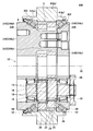
- FIG. 2 shows an enlarged sectional view of a range II in FIG. 1.
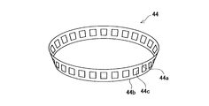
- the schematic of the external appearance of a retainer is shown.
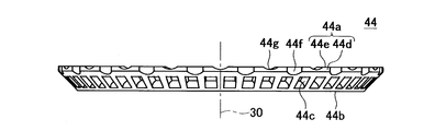
- the figure which looked at the retainer from the bearing central axis direction (plan view) is shown.
- the figure (front view) which looked at the retainer from the direction orthogonal to a bearing central axis is shown.
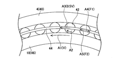
- movement of a roller is shown.
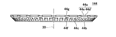
- the top view of the retainer used with the gear transmission of 2nd Example is shown.
- the front view of the retainer used with the gear transmission of 2nd Example is shown.
- the top view of the retainer used with the gear transmission of 3rd Example is shown.
- the front view of the retainer used with the gear transmission of 3rd Example is shown.
- Sectional drawing of the gear transmission of 4th Example is shown.
- the first member may have a ring shape that is detachable from the case.
- the second member may have a ring shape that can be attached to and detached from the carrier.
- a material obtained by processing polytetrafluoroethylene (PTFE), wholly aromatic polyimide (API), brass, sintered metal, ceramics, or the like into a ring shape can be used.
- PTFE polytetrafluoroethylene
- API wholly aromatic polyimide
- brass sintered metal, ceramics, or the like into a ring shape
- a ring-shaped steel plate obtained by nitriding treatment, hard chrome plating treatment, or the like, or a surface treatment of polyvinyl chloride (PVC) or the like can be used.
- PVC polyvinyl chloride
- the steel plate SPCC defined in JIS G 3141 can be used.
- the first member may be a part of the case coated.
- the second member may be a part of the case coated.
- As a coating material PTFE, API, hard chrome, or the like can be used.
- cast iron such as FC defined in JIS G 5501 or FCD defined in JIS G 5502
- carbon steel for mechanical structures such as SC defined in JIS G 4051
- JIS G Alloy steel for mechanical structure such as SNCM, SCM, SCr, aluminum, plastic, etc. specified in 4053
- the contact area between the retainer and the first member and the contact area between the retainer and the second member may be equal. Thereby, sliding of the retainer with respect to the first member and sliding of the retainer with respect to the second member can be made uniform.
- the rotational speed of the retainer relative to the case can be made closer to approximately half of the rotational speed of the carrier relative to the case.
- the contact surface between the retainer and the first member is perpendicular to the carrier axis
- the contact surface between the retainer and the second member is a cylindrical surface concentric with the carrier axis.
- the contact surface between the retainer and the second member may be orthogonal to the carrier axis
- the contact surface between the retainer and the first member may be a cylindrical surface concentric with the carrier axis.
- a groove may be formed on a surface (carrier contact surface) that contacts the second member (carrier) of the retainer.
- channel may be formed in the surface (case contact surface) which contacts the 1st member (case) of a retainer.
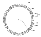
- FIG. 1 shows a cross-sectional view of the gear transmission 100.
- the gear transmission 100 is an eccentric oscillating speed reduction device.
- the external gear 22 rotates eccentrically while meshing with the internal gear 24.
- the number of teeth of the external gear 22 is different from the number of teeth of the internal gear 24.
- the gear transmission 100 uses the difference between the number of teeth of the external gear 22 and the number of teeth of the internal gear 24 to rotate the carrier 10. That is, the gear transmission 100 uses the difference in the number of teeth between the external gear 22 and the internal gear 24 to increase the torque transmitted to the crankshaft 16 (decelerate the rotation) and output it from the carrier 10.
- the carrier 10 corresponds to the output unit of the gear transmission 100.
- the axis 30 corresponds to the rotation axis of the carrier 10.
- the axis 30 also corresponds to the central axis of the internal gear 24.
- the axis 30 also corresponds to the axis of the gear transmission 100. Further, the axis 30 corresponds to a bearing central axis of a cylindrical roller bearing 2 described later.
- the gear transmission 100 includes an internal gear 24, a carrier 10, an external gear 22, and a crankshaft 16.
- the internal gear 24 includes a case 4 and a plurality of internal gear pins 5.
- the case 4 has a small diameter portion 4a and a large diameter portion 4b.
- the small diameter portion 4a extends along the axis 30 from both ends of the large diameter portion 4b.
- the internal gear 24 is formed in the large diameter portion 4 b of the case 4.
- a pair of cylindrical roller bearings 2 is disposed in the small diameter portion 4a.
- a ring-shaped first member 52 is attached to a part of the small diameter portion 4a. Details of the first member 52 will be described later.
- the internal gear 24 is disposed between the pair of cylindrical roller bearings 2 in the direction of the axis 30.
- the external gear 22 meshes with the internal gear 24. Therefore, it can also be said that the external gear 22 is disposed between the pair of cylindrical roller bearings 2 in the direction of the axis 30.
- the pair of cylindrical roller bearings 2 restricts the carrier 10 from moving in the axial direction and the radial direction.
- the pair of cylindrical roller bearings 2 can be called main bearings of the gear transmission 100. Details of the cylindrical roller bearing 2 will be described later.
- the carrier 10 is supported on the case 4 by a pair of cylindrical roller bearings 2.
- the carrier 10 includes a first plate 10a and a second plate 10c.
- the first plate 10a includes a columnar portion 10b.
- the columnar portion 10b extends from the first plate 10a toward the second plate 10c, and is fixed to the second plate 10c.
- a first flange 10d is formed at the end of the first plate 10a.
- the first flange 10d extends in the radial direction (the direction orthogonal to the axis 30).
- a second flange 10e is formed at the end of the second plate 10c.
- the second flange 10e extends in the radial direction.
- the cylindrical roller bearing 2 is disposed on the first flange 10d and the second flange 10e.
- the first flange 10d can also be referred to as a protruding portion of the first plate 10a.
- the second flange 10e can also be called a protruding portion of the second plate 10c.
- a ring-shaped second member 50 is attached to a part of the first flange 10d and a part of the second flange 10e. Details of the second member 50 will be described later.
- the carrier 10 and the case 4 are made of metal. Specifically, the material of the carrier 10 is FCD450 defined by JIS G 5502 or S55C defined by JIS G 4051, and the material of the case 4 is FCD450.
- the crankshaft 16 is supported on the carrier 10 by a pair of tapered roller bearings 19.
- the pair of tapered roller bearings 19 restricts the crankshaft 16 from moving in the axial direction and the radial direction.
- the crankshaft 16 extends parallel to the axis 30 at a position offset from the axis 30.
- the crankshaft 16 includes an input gear 28 and an eccentric body 18.
- the input gear 28 is fixed to the crankshaft 16 outside the pair of tapered roller bearings 19.
- the eccentric body 18 is located between the pair of tapered roller bearings 19.
- a through hole 14 is formed in the external gear 22.
- the eccentric body 18 is engaged with the through hole 14 via the cylindrical roller bearing 20.
- the external gear 22 is supported by the carrier 10 via the crankshaft 16. In the direction of the axis 30, the external gear 22 is disposed between the pair of tapered roller bearings 19.
- the crankshaft 16 rotates.
- the eccentric body 18 rotates eccentrically.
- the eccentric body 18 rotates eccentrically around the axis (not shown) of the crankshaft 16.
- the external gear 22 rotates eccentrically while meshing with the internal gear 24.
- the external gear 22 rotates eccentrically around the axis 30.
- the number of teeth of the external gear 22 and the number of teeth of the internal gear 24 are different. Therefore, when the external gear 22 rotates eccentrically, the carrier 10 that supports the external gear 22 is connected to the internal gear 24 (case 4) according to the difference in the number of teeth between the external gear 22 and the internal gear 24. Rotate against.
- the cylindrical roller bearing 2 will be described in detail with reference to FIG.
- the cylindrical roller bearing 2 includes an inner race 46, an outer race 40, a roller 42 (cylindrical roller), and a retainer 44.
- the inner race 46 has a ring shape.
- the outer peripheral surface 46b of the inner race 46 is tapered. That is, the outer peripheral surface 46b of the inner race 46 is inclined with respect to the axis 30 (see FIG. 1). In the direction of the axis 30, the diameter of the outer peripheral surface 46 b becomes smaller toward the inside of the gear transmission 100. Ribs that restrict the movement of the roller 42 are not provided on the outer peripheral surface 46 b of the inner race 46.
- the inner race 46 is press-fitted outside the second plate 10 c of the carrier 10.
- the inner peripheral surface 46a of the inner race 46 is in contact with the outer peripheral surface of the second plate 10c.
- An end face 46c in the direction of the axis 30 of the inner race 46 is in contact with the second flange 10e.
- An end surface 46 c of the inner race 46 in the direction of the axis 30 is not in contact with the second member 50.
- the inner race 46 is attached to the carrier 10 and does not move with respect to the carrier 10 both in the direction of the axis 30 and in the radial direction. It can also be said that the inner race 46 is integrated with the carrier 10.
- the outer race 40 has a ring shape.
- the inner peripheral surface 40b of the outer race 40 is tapered.
- the inner peripheral surface 40 b of the outer race 40 is inclined with respect to the axis 30. In the direction of the axis 30, the diameter of the inner peripheral surface 40 b increases toward the inside of the gear transmission 100.
- the inner race surface 40 b of the outer race 40 is not provided with a rib that restricts the movement of the roller 42.
- the inner peripheral surface 40 b of the outer race 40 faces the outer peripheral surface 46 b of the inner race 46.
- the inclination angle of the inner peripheral surface 40b with respect to the axis 30 is equal to the inclination angle of the outer peripheral surface 46b with respect to the axis 30.
- a gap between the inner peripheral surface 40 b of the outer race 40 and the outer peripheral surface 46 b of the inner race 46 is constant in the rotation axis direction of the roller 42.
- the outer race 40 is press-fitted inside the small diameter portion 4 a of the case 4.
- the outer peripheral surface 40a of the outer race 40 is in contact with the inner peripheral surface of the case 4 (small diameter portion 4a).
- the outer peripheral surface 40 a of the outer race 40 is not in contact with the second member 50.
- An end surface 40 c in the direction of the axis 30 of the outer race 40 is in contact with the large diameter portion 4 b of the case 4.
- the outer race 40 is attached to the case 4 and is immovable with respect to the case 4 both in the direction of the axis 30 and in the radial direction. It can also be said that the outer race 40 is integrated with the case 4.
- the roller (cylindrical roller) 42 is disposed between the inner race 46 and the outer race 40.
- the rotation axis of the roller 42 is inclined with respect to the axis 30 (see FIG. 1).
- a plurality of rollers 42 are arranged at equal intervals between the inner race 46 and the outer race 40. That is, the plurality of rollers 42 are arranged at equal intervals around the axis 30.
- the roller 42 has a cylindrical shape.
- the length of the roller 42 in the rotation axis direction is shorter than the lengths of the outer peripheral surface 46 b of the inner race 46 and the inner peripheral surface 40 b of the outer race 40.
- the outer peripheral surface of the roller 42 is in contact with the outer peripheral surface 46 b of the inner race 46 and the inner peripheral surface 40 b of the outer race 40.
- the retainer 44 is disposed between the inner race 46 and the outer race 40.
- the material of the retainer 44 is resin.
- the retainer 44 has a ring shape, and has a first end 44a having a large diameter and a second end 44b having a smaller diameter than the first end 44a.
- the retainer 44 has a plurality of pockets 44c arranged in the circumferential direction. A roller 42 is inserted into the pocket 44c. The retainer 44 maintains an interval between the adjacent rollers 42. Further, since the roller 42 is inserted into the pocket 44c, both ends 42a of the roller 42 in the rotation axis direction are restrained by the retainer 44 (see also FIG. 2).
- FIG. 3 is a diagram for simply explaining the overall shape of the retainer 44, and does not accurately show the shape of the retainer 44. The detailed shape of the retainer 44 will be described later.
- a case contact surface 44 d that contacts the case 4 and a carrier contact surface 44 e that contacts the carrier 10 are formed on the first end 44 a of the retainer 44.
- the case contact surface 44d is formed in a direction orthogonal to the axis 30 (see FIG. 1).
- the case contact surface 44d is an outer peripheral surface of the retainer 44, and contacts the inner peripheral surface of the case 4 (small diameter portion 4a) via the first member 52.
- the contact surface between the retainer 44 and the case 4 has a cylindrical shape concentric with the bearing center shaft 30.
- the carrier contact surface 44e is formed at an end in the direction of the axis 30.
- the carrier contact surface 44e is an end surface of the retainer 44 in the bearing central axis 30 direction.
- the carrier contact surface 44e contacts the second flange 10e of the carrier 10 (second plate 10c) via the second member 50.
- the contact surface between the retainer 44 and the carrier 10 is orthogonal to the axis 30.
- the retainer 44 will be described in detail with reference to FIGS.
- the case contact surface 44d is formed on the circumference concentric with the bearing center shaft 30 (the outer peripheral surface of the retainer 44).
- a plurality of outer peripheral grooves 44f are formed on the case contact surface 44d.
- the outer circumferential grooves 44 f extend along the bearing center axis 30 and are formed at equal intervals around the bearing center axis 30. It can also be expressed that the case contact surface 44d is formed between the adjacent outer peripheral grooves 44f. Even if the case contact surface 44 d contacts the case 4 (first member 52), the outer peripheral groove 44 f does not contact the case 4. That is, even when the case contact surface 44 d comes into contact with the case 4, a gap is secured between the retainer 44 and the case 4.
- the carrier contact surface 44e is formed on a plane orthogonal to the bearing central axis 30.
- a plurality of end face grooves 44g are formed on the carrier contact surface 44e.
- the end surface grooves 44 g extend along the radial direction of the retainer 44 and are formed at equal intervals around the bearing center shaft 30. It can also be expressed that the carrier contact surface 44e is formed between the adjacent end surface grooves 44g.
- the end surface groove 44g communicates the inside and the outside of the retainer 44. Even if the carrier contact surface 44e contacts the carrier 10 (second member 50), the end surface groove 44g does not contact the carrier 10. That is, even when the carrier contact surface 44 e comes into contact with the carrier 10, a gap is secured between the retainer 44 and the carrier 10.
- the outer peripheral grooves 44 f and the end surface grooves 44 g are alternately formed in the circumferential direction of the retainer 44.
- the outer peripheral groove 44f is formed between the adjacent end surface grooves 44g
- the end surface groove 44g is formed between the adjacent outer peripheral grooves 44f.
- the number of outer peripheral grooves 44f and end face grooves 44g are equal.
- the area of the case contact surface 44d is substantially equal to the area of the carrier contact surface 44e. That is, the area W1 of the contact surface between the retainer 44 and the case 4 shown in FIG. 2 is substantially equal to the area W2 of the contact surface between the retainer 44 and the carrier 10.
- FIG. 2 shows a state where the case contact surface 44 d is in contact with the case 4 and the carrier contact surface 44 e is in contact with the carrier 10. That is, the first end portion 44a of the retainer 44 is in contact with the case 4 in a direction perpendicular to the bearing center shaft 30 (the radial direction of the retainer 44), and in contact with the carrier 10 in the direction of the bearing center shaft 30. ing.
- the case contact surface 44d and the carrier contact surface 44e may not be in contact with the case 4 and the carrier 10. What is important is that the case contact surface 44d and the carrier contact surface 44e come into contact with the case 4 and the carrier 10, respectively, when a force that moves outward is applied to the roller 42.
- FIG. 6 is a view for explaining the operation of the roller 42 and the retainer 44 when the carrier 10 rotates with respect to the stationary case 4.
- FIG. 6 is a view for explaining the concept of the operation of the roller 42 and the retainer 44, and does not accurately represent the structure of the gear transmission 100.
- the inner race 46 of the cylindrical roller bearing 2 is integrated with the carrier 10.
- the outer race 40 is integrated with the case 4. Therefore, in FIG. 6, the inner race 46 and the carrier 10 are shown as one part, and the outer race 40 and the case 4 are shown as one part.
- the roller 42 shown in FIG. 6 shows the cross section orthogonal to a rotating shaft direction.
- the roller 42 moves in the arrow A3 direction while rotating in the arrow A2 direction. That is, the roller 42 moves in the arrow A3 direction while rolling on the outer peripheral surface of the carrier 10 and the inner peripheral surface of the case 4.
- the retainer 44 rotates in the arrow A3 direction as the roller 42 moves.
- the retainer 44 rotates at about half the rotation speed V of the carrier 10 (rotation speed 0.5 V). To do.
- the speed of the roller 42 approaches the speed of the carrier 10.
- the speed of the roller 42 approaches the speed (zero) of the case 4.
- the first end 44a of the retainer 44 contacts both the case 4 and the carrier 10 (see also FIG. 2).
- a frictional force F1 is generated between the retainer 44 and the case 4 in the arrow A4 direction.
- a frictional force F2 is generated between the retainer 44 and the carrier 10 in the direction of arrow A5.
- the contact area W1 between the retainer 44 and the case 4 is substantially equal to the contact area W2 between the retainer 44 and the carrier 10. Therefore, the friction force F1 is substantially equal to the friction force F2.
- the retainer 44 rotates in the arrow A3 direction at a speed close to the rotational speed of 0.5V.
- the roller 42 also moves in the arrow A3 direction at a speed close to the rotational speed 0.5V.
- the fact that the roller 42 moves in the direction of the arrow A3 at a speed close to the rotational speed 0.5V means that the friction between the roller 42 and the carrier 10 and between the roller 42 and the case 4 is small. In other words, the sliding of the roller 42 with respect to the carrier 10 and the case 4 is small. Therefore, wear of the roller 42 (deterioration of the cylindrical roller bearing 2) is suppressed.
- the retainer is brought into contact with only the case as in Patent Document 1 described above, only the friction force in the direction of the friction force F1 in FIG. 6 is generated, and the friction force in the direction of the friction force F2 cannot be obtained. For this reason, the rotation speed of the retainer is decreased, and friction between the roller and the carrier and between the roller and the case is increased.
- the wear of the roller is promoted, and the durability of the gear transmission is lowered.
- the gear transmission 100 shown in the present embodiment can suppress wear of the roller 42 while restraining the movement of the roller 42 in the axial direction by bringing the retainer 44 into contact with both the carrier 10 and the case 4. .
- the retainer 44 contacts the case 4 via the first member 52. That is, the retainer 44 does not directly contact the case 4.
- the first member 52 makes the friction generated between the first member 52 and the retainer 44 smaller than the friction generated when the retainer 44 comes into contact with the case 4 without passing through the first member 52.
- the retainer 44 contacts the carrier 10 via the second member 50 and does not directly contact the carrier 10.
- the second member 50 makes the friction generated between the second member 50 and the retainer 44 smaller than the friction generated when the retainer 44 contacts the carrier 10 without passing through the second member 50.
- the first member 52 and the second member 50 are PTFE resin processed into a link shape, and are fitted into the case 4 and the carrier 10, respectively.
- the length of the first member 52 is longer than the length of the case contact surface 44 d.
- the retainer 44 can be restricted from contacting the case 4 directly.
- the length of the first member 52 in the direction of the axis 30 is longer than the length in the radial direction (direction perpendicular to the axis 30).
- the length of the second member 50 is longer than the length of the carrier contact surface 44.
- the retainer 44 can be restricted from coming into direct contact with the carrier 10.
- the length in the radial direction of the second member 50 is longer than the length in the direction of the axis 30.
- the surface roughness of the first member 52 is smaller than the surface roughness of the case 4 at the position where the first member 52 is disposed.
- the surface roughness of the second member 50 is smaller than the surface roughness of the carrier 10 at the position where the second member 50 is disposed.
- the material of the case 4 is FCD450
- the material of the carrier 10 is FCD450 or S55C.
- the friction generated between the retainer 44 and the first member (PTFE resin) 52 when the retainer 44 and the first member 52 are in contact with each other is smaller than the friction generated between the retainer 44 and the case 4.
- the friction generated between the retainer 44 and the second member (PTFE resin) 50 when the retainer 44 and the second member (PTFE resin) 50 contact is smaller than the friction generated between the retainer 44 and the carrier 10.
- cast iron such as FC and FCD
- carbon steel for machine structure such as SC
- alloy steel for machine structure such as SNCM, SCM and SCr
- first member 52 and / or the second member 50 PTFE, API, brass, sintered metal, ceramics, or the like processed into a ring shape can be used.
- first member 52 and / or the second member 50 can be formed by coating PTFE, API, or hard chrome on a part of the case 4 and / or the carrier 10.
- the cylindrical roller bearing 2 disposed between the case 4 and the first plate 10a has the same characteristics as the cylindrical roller bearing 2 disposed between the case 4 and the second plate 10c (see FIG. 1). Therefore, the description about the cylindrical roller bearing 2 arrange
- the contact surface between the retainer 44 and the case 4 has a cylindrical shape concentric with the axis 30. Further, the contact surface between the retainer 44 and the carrier 10 is orthogonal to the axis 30. By having such a feature, the movement of the retainer 44 is restricted in two orthogonal directions (the axial direction and the radial direction of the gear transmission 100). It is possible to reliably prevent the retainer 44 (roller 42) from being detached from the gear transmission 100.
- the retainer 44 contacts both the case 4 and the carrier 10. For this reason, the retainer 44 can prevent foreign matter from entering the case 4 from the outside of the gear transmission 100.
- the oil seal 6 is arrange
- the groove 26 makes a round around the outer periphery of the small diameter portion 4a.
- an O-ring (not shown) is disposed in the groove 26.
- the lubricant sealed in the gear transmission 100 can be prevented from leaking out of the gear transmission 100 by the oil seal 6 and the O-ring disposed in the groove 26.
- an outer peripheral groove 44 f is formed on the case contact surface 44 d of the retainer 44
- an end surface groove 44 g is formed on the carrier contact surface 44 e of the retainer 44. Therefore, even if the retainer 44 contacts both the case 4 and the carrier 10, the lubricant present outside the cylindrical roller bearing 2 can be introduced into the cylindrical roller bearing 2. It is possible to suppress the lubricant in the cylindrical roller bearing 2 from being exhausted (out of oil). More specifically, the lubricant present in the vicinity of the oil seal 6 can be introduced into the cylindrical roller bearing 2 through the outer peripheral groove 44f and the end surface groove 44g.
- the retainer 44 When a force to move the roller 42 outward acts on the roller 42, the retainer 44 is pressed against the case 4 and the carrier 10.
- the retainer 44 is made of resin, and the case 4 and the carrier 10 are made of metal. That is, the retainer is formed of a material having lower rigidity than the carrier and the case. Since the rigidity of the retainer 44 is lower than the rigidity of the case 4 and the carrier 10, when the retainer 44 is pressed against the case 4 and the carrier 10, the retainer 44 can be deformed. As a result, the entire circumferential direction of the retainer 44 contacts the case 4 and the carrier 10 uniformly. That is, it is difficult to form a gap between the case contact surface 44 d and the case 4 and between the carrier contact surface 44 e and the carrier 10.
- a central through hole 12 is formed in the center of the gear transmission 100 along the direction of the axis 30.
- the central through hole 12 can be used to allow wiring, piping, etc. to pass through the gear transmission 100.
- the gear transmission of the second embodiment will be described with reference to FIGS.
- the gear transmission of this embodiment is different from the gear transmission 100 only in the shape of the retainer.
- the retainer 144 of the present embodiment is different from the retainer 44 in the positional relationship between the outer peripheral groove formed on the case contact surface and the end surface groove formed on the carrier contact surface.
- Features common to the retainer 144 and the retainer 44 may be omitted from description because the same or the last two digits are given the same number.
- the outer circumferential groove 44f and the end surface groove 44g are formed at the same position. Therefore, the outer peripheral groove 44f and the end face groove 44g are continuous.
- the lubricant existing outside the cylindrical roller bearing 2 is introduced into the cylindrical roller bearing 2 through the outer peripheral groove 44f and the end surface groove 44g. By using the retainer 144, the lubricant is more easily introduced into the cylindrical roller bearing 2.
- the gear transmission of the third embodiment will be described with reference to FIGS.
- the gear transmission of this embodiment is different from the gear transmission 100 only in the shape of the retainer.
- the retainer 244 of this embodiment is different from the retainer 44 in the shape of the outer peripheral groove formed on the case contact surface and the shape of the end surface groove formed on the carrier contact surface.
- Features common to the retainer 244 and the retainer 44 may be omitted from description because the same or the last two digits are given the same number.
- a plurality of end surface grooves 244g are formed in the carrier contact surface 244e.
- the extending direction of the end face groove 244g is inclined with respect to a straight line connecting the outer peripheral surface (case contact surface 244d) of the cage 244 and the bearing center axis 30 (FIG. 4). See for comparison).
- Each of the plurality of end surface grooves 244g is inclined in the same direction.
- a plurality of outer peripheral grooves 244f are formed on the case contact surface 244d.
- the direction in which the outer circumferential groove 244f extends is inclined with respect to the bearing central axis 30 (see FIG. 5 for comparison).
- Each of the plurality of outer peripheral grooves 244f is inclined in the same direction.
- the end surface grooves 244g and the outer peripheral grooves 244f are alternately formed in the circumferential direction of the retainer 44. That is, the end face grooves 244g are formed between adjacent outer peripheral grooves 244f, and the outer peripheral grooves 244f are formed between adjacent end face grooves 244g.
- the retainer 244 rotates relative to the carrier 10 and the case 4.
- the lubricant can smoothly move in the end surface groove 244g as the retainer 244 rotates.
- the outer peripheral groove 244f is inclined, the lubricant can smoothly move in the outer peripheral groove 244f as the retainer 244 rotates. Note that like the retainer 144, the end surface groove 244g and the outer peripheral groove 244f may be continuous.
- the gear transmission 300 will be described with reference to FIG.
- the gear transmission 300 is a modification of the gear transmission 100, and the same parts as the gear transmission 100 may be denoted by the same or lower two digits with the same numbers, and the description may be omitted.
- inclined portions 346 are provided at the radial ends of the first plate 310a and the second plate 310c.
- the inclined portion 346 also serves as an inner race of the cylindrical roller bearing 302. That is, the inner race of the cylindrical roller bearing 302 is integrated with the carrier 310. Such a configuration can also be said that the inner race is attached to the carrier 310.
- a flange 310d is formed outside the inclined portion 346 of the first plate 310a in the direction of the axis 30. In the direction of the axis 30, a flange 310 e is formed outside the inclined portion 346 of the second plate 310 c.
- the retainer 44 is the same as the retainer 44 used in the gear transmission 100. Therefore, the retainer 44 contacts both the flange 210d and the flange 210e.
- the contact area between the retainer and the case is equal to the contact area between the retainer and the carrier.
- the contact area between the retainer and the case may be larger than the contact area between the retainer and the carrier.
- the contact area between the retainer and the carrier may be larger than the contact area between the retainer and the case.
- an example in which the outer race is attached to the case and the inner race is attached to the carrier has been described.
- An inner race may be attached to the case, and an outer race may be attached to the carrier.
- the case where the case is stationary and the carrier rotates with respect to the case has been described.
- the technology disclosed in this specification can also be applied to a gear transmission in which the carrier is stationary and the case rotates with respect to the carrier.
- the technology disclosed in this specification can also be applied to a gear transmission in which a crankshaft is arranged coaxially with the axis of a carrier.
- the technology disclosed in this specification can also be applied to a gear transmission different from the eccentric oscillating type.
- the case may double as an outer race.
- the carrier may double as an inner race, and the case may double as an outer race.
- a cylindrical roller bearing is provided between the case and the carrier, the rotation axis of the roller of the cylindrical roller bearing is inclined with respect to the axis of the carrier, and a retainer for holding the roller is provided on both the case and the carrier. Is to contact.
Abstract
キャリアが、軸受を介してケースに支持されている。軸受は、インナーレース、アウターレース、複数のローラ、リテーナを備えている。インナーレースは、テーパー状の外周面を有し、キャリアに固定されている。アウターレースは、インナーレースの外周面に対向するテーパー状の内周面を有し、ケースに固定されている。複数のローラは、インナーレースとアウターレースの間に配置されている。リテーナの直径の大きい方の端部が、第1部材を介してケースと接触する。リテーナの直径の大きい方の端部が、第2部材を介してケースと接触する。リテーナが第1部材及び第2部材を介してケース及びキャリアと接触することにより、リテーナがケース及びキャリアと直接接触するときより摩擦を小さくすることができる。
Description
本出願は、2013年3月25日に出願された日本国特許出願第2013-62082号に基づく優先権を主張する。その出願の全ての内容は、この明細書中に参照により援用されている。本明細書は、歯車伝動装置に関する技術を開示する。特に、キャリアとケースの間に円筒ころ軸受を備える歯車伝動装置に関する技術を開示する。
複数の歯車がケース内に収容されており、キャリアが軸受を介してケースに支持されている歯車伝動装置が知られている。特開2010-159774号公報(以下、特許文献1と称する)には、ケースとキャリアの間に円筒ころ軸受が配置されている歯車伝動装置が開示されている。特許文献1の円筒ころ軸受では、円柱状のローラ(転動体)が、キャリアの軸線に対して傾いている。ローラがキャリアの軸線に対して傾いているので、キャリアの回転に伴って、ローラを外側へ移動させようとする力がローラに加わる。
特許文献1の技術では、リテーナに、ローラの軸方向への移動を規制する機能を持たせている。すなわち、リテーナが、ローラが軸方向へ移動することを規制している。具体的には、リング状のリテーナの大径側の端部がケースに接触する。リテーナは、ローラを保持している。リテーナがケースに接触することによって、リテーナの移動が規制される。その結果、リテーナに保持されているローラの軸方向への移動が規制される。
歯車伝動装置には、キャリアが出力部として回転するタイプと、ケースが出力部として回転するタイプがある。どちらの歯車伝動装置においても、キャリアとケースは、相対的に回転する。以下の説明では、ケースが静止しており、キャリアが出力部として回転するタイプの歯車伝動装置について説明する。キャリアが回転すると、円筒ころ軸受のローラは、回転しながらキャリアの軸線の周りを移動する。すなわち、ローラは、ケースの内周面を転がるとともに、キャリアの外周面を転がる。換言すると、ローラはアウターレースの内周面を転がるとともに、インナーレースの外周面を転がる。リテーナは、ローラの移動に伴って、ケースに対して回転する。
特許文献1のようにリテーナをケースに接触させると、リテーナとケースの間に摩擦が生じる。その結果、ケースに対するリテーナの回転速度が遅くなり、ローラの移動速度が遅くなる。ローラが、ケース及びキャリアに対して滑りやすくなる。ケース及びキャリアに対するローラの摺動が大きくなり、ローラに磨耗が生じやすくなる。それにより、円筒ころ軸受の劣化が促進され、歯車伝動装置の耐久性が低下することがある。本明細書は、ケースとキャリアの間に配置する円筒ころ軸受の劣化を抑制する技術を提供する。
本明細書が開示する技術は、キャリアが軸受を介してケースに支持されている歯車伝動装置に関する。その軸受は、インナーレースと、アウターレースと、複数の円柱状のローラと、リング状のリテーナを備えている。インナーレースは、ケースとキャリアの一方に取り付けられている。アウターレースは、ケースとキャリアの他方に取り付けられている。複数の円柱状のローラは、インナーレースとアウターレースの間に配置されている。リテーナは、隣り合うローラ同士の間隔を維持する。インナーレースは、テーパー状の外周面を有している。アウターレースは、テーパー状の内周面を有している。アウターレースの内周面は、インナーレースの外周面に対向している。リテーナは、インナーレースとアウターレースの間に配置されており、隣り合うローラ間の間隔を維持する。歯車伝動装置はさらに、第1部材と第2部材を備えている。第1部材は、ケースとリテーナの間でケースに固定されている。第2部材は、キャリアとリテーナの間でキャリアに固定されている。本明細書が開示する歯車伝動装置では、リテーナの直径の大きい方の端部が、第1部材を介してケースに接触するとともに、第2部材を介してキャリアに接触する。第1部材とリテーナの間に生じる摩擦は、リテーナが第1部材を介することなくケースに接触するときに生じる摩擦より小さい。また、第2部材とリテーナの間に生じる摩擦は、リテーナが第2部材を介することなくキャリアに接触するときに生じる摩擦より小さい。すなわち、第1部材は、第1部材とリテーナの間に生じる摩擦を、リテーナが第1部材を介することなくケースに接触するときに生じる摩擦より小さくするように構成されている。第2部材は、第2部材とリテーナの間に生じる摩擦を、リテーナが第2部材を介することなくキャリアに接触するときに生じる摩擦より小さくするように構成されている。
上記の歯車伝動装置によると、リテーナは、ケース(第1部材)とキャリア(第2部材)の双方に接触することにより、ケースに対して摺動するだけでなく、キャリアに対しても摺動する。上述したように、従来の歯車伝動装置では、リテーナをケースにのみ接触させる。本明細書で開示する歯車伝動装置では、従来の歯車伝動装置と比較して、リテーナとキャリア(第2部材)の間に生じる摩擦の分だけケースに対するリテーナの回転速度が速くなる。別言すると、本明細書で開示する歯車伝動装置は、ケースに対するリテーナの回転速度を、ケースに対するキャリアの回転速度のほぼ半分に近づけることができる。すなわち、ケースに対するリテーナの回転速度を、リテーナがケースとキャリアのどちらにも接触しないときの回転速度に近づけることができる。ケース及びキャリアに対するローラの摺動が抑制され、ローラの磨耗が抑制される。円筒ころ軸受の劣化が抑制され、歯車伝動装置の耐久性が向上する。
また、上記歯車装置によると、ケースとリテーナの間に第1部材が配置され、キャリアとリテーナの間に第2部材が配置される。その結果、リテーナが、ケース及びキャリアと直接接触することが防止される。リテーナとケースの間、及び、リテーナとキャリアの間に生じる摩擦を小さくすることができる。その結果、キャリアを回転させるための回転トルクが増大することを抑制することができる。
なお、上記の歯車伝動装置では、リテーナは、常にケースとキャリアの双方に接触している必要はない。歯車伝動装置の静止中は、リテーナがケースとキャリアから離れていてもよい。歯車伝動装置の駆動中に、ローラを外側へ移動させようとする力がローラに作用したときに、リテーナがケースとキャリア(第1部材と第2部材)の双方に接触すればよい。
以下、本明細書で開示する実施例の技術的特徴の幾つかを記す。なお、以下に記す事項は、各々単独で技術的な有用性を有している。
第1部材は、ケースと着脱可能なリング状であってよい。また、第2部材が、キャリアと着脱可能なリング状であってよい。第1部材又は第2部材として、ポリテトラフルオロエチレン(PTFE),全芳香族ポリイミド(API),黄銅,焼結金属,セラミックス等をリング状に加工したものを用いることができる。あるいは、第1部材又は第2部材として、リング状の鋼板を窒化処理,硬質クロムめっき処理等したもの、ポリ塩化ビニル(PVC)等を表面処理したものを用いることができる。上記鋼板として、JIS G 3141で規定されているSPCC等を用いることができる。
第1部材は、ケースの一部をコーティング処理したものでもよい。また、第2部材は、ケースの一部をコーティング処理したものでもよい。コーティング材料として、PTFE,API,硬質クロム等を用いることができる。
ケース及び/又はキャリアの材料として、JIS G 5501で規定されているFC又はJIS G 5502で規定されているFCD等の鋳鉄、JIS G 4051で規定されているSC等の機械構造用炭素鋼、JIS G 4053で規定されているSNCM,SCM,SCr等の機械構造用合金鋼、アルミニウム、プラスチック等を用いることができる。
本明細書で開示する歯車伝動装置では、リテーナと第1部材の接触面積と、リテーナと第2部材の接触面積が等しくてもよい。これにより、第1部材に対するリテーナの摺動と、第2部材に対するリテーナの摺動とを均等にすることができる。ケースに対するリテーナの回転速度を、ケースに対するキャリアの回転速度のほぼ半分にさらに近づけることができる。
本明細書で開示する歯車伝動装置では、リテーナと第1部材の接触面がキャリアの軸線に直交しており、リテーナと第2部材の接触面がキャリアの軸線と同心の円筒面であってもよい。あるいは、リテーナと第2部材の接触面がキャリアの軸線に直交しており、リテーナと第1部材の接触面がキャリアの軸線と同心の円筒面であってもよい。これにより、リテーナを、キャリアの軸線方向とキャリアの径方向の2方向で支えることができる。リテーナがローラの軸方向に移動することを、確実に防止することができる。なお、「接触面がキャリアの軸線に直交している」とは、キャリアの軸線が接触面に垂直であることを意味する。
本明細書で開示する歯車伝動装置では、リテーナの第2部材(キャリア)と接触する面(キャリア接触面)に、溝が形成されていてもよい。また、リテーナの第1部材(ケース)と接触する面(ケース接触面)に、溝が形成されていてもよい。キャリア接触面とケース接触面の少なくとも一方に溝が形成されていると、リテーナが第1部材と第2部材に接触したときに、円筒ころ軸受の外部から内部に潤滑剤が導入されやすくなる。すなわち、円筒ころ軸受の外部から内部への潤滑剤の通路が確保される。その結果、リテーナが第1部材と第2部材に接触しても、潤滑剤が、上記溝を通って、円筒ころ軸受の内部に移動することができる。ローラの油膜切れが抑制され、ローラの磨耗が進行することが抑制される。
(第1実施例)
実施例では、外歯歯車が内歯歯車と噛み合いながら偏心回転するタイプの歯車伝動装置について説明する。本明細書が開示する技術は、他のタイプの歯車伝動装置、例えば、内歯歯車が外歯歯車と噛み合いながら偏心回転するタイプの歯車伝動装置に適用することもできる。なお、以下の説明では、リテーナが第1部材を介してケースに接触することを単に「リテーナがケースに接触する」と表現し、リテーナが第2部材を介してキャリアに接触することを単に「リテーナがキャリアに接触する」と表現することがある。
実施例では、外歯歯車が内歯歯車と噛み合いながら偏心回転するタイプの歯車伝動装置について説明する。本明細書が開示する技術は、他のタイプの歯車伝動装置、例えば、内歯歯車が外歯歯車と噛み合いながら偏心回転するタイプの歯車伝動装置に適用することもできる。なお、以下の説明では、リテーナが第1部材を介してケースに接触することを単に「リテーナがケースに接触する」と表現し、リテーナが第2部材を介してキャリアに接触することを単に「リテーナがキャリアに接触する」と表現することがある。
図1は、歯車伝動装置100の断面図を示す。歯車伝動装置100は、偏心揺動型の減速装置である。外歯歯車22は、内歯歯車24と噛み合いながら偏心回転する。外歯歯車22の歯数は、内歯歯車24の歯数と異なる。歯車伝動装置100は、外歯歯車22の歯数と内歯歯車24の歯数との差を利用し、キャリア10を回転させる。すなわち、歯車伝動装置100は、外歯歯車22と内歯歯車24の歯数差を利用し、クランクシャフト16に伝達されたトルクを増大して(回転を減速して)、キャリア10から出力する。なお、キャリア10は、歯車伝動装置100の出力部に相当する。軸線30は、キャリア10の回転軸線に相当する。軸線30は、内歯歯車24の中心軸にも相当する。また、軸線30は、歯車伝動装置100の軸線にも相当する。さらに、軸線30は、後述する円筒ころ軸受2の軸受中心軸にも相当する。
歯車伝動装置100は、内歯歯車24と、キャリア10と、外歯歯車22と、クランクシャフト16を備えている。内歯歯車24は、ケース4と複数の内歯ピン5を備えている。ケース4は、小径部4aと大径部4bを有する。小径部4aは、大径部4bの両端から軸線30に沿って延びている。内歯歯車24は、ケース4の大径部4bに形成されている。小径部4aには、一対の円筒ころ軸受2が配置されている。小径部4aの一部に、リング状の第1部材52が取り付けられている。第1部材52の詳細については後述する。
軸線30方向において、内歯歯車24は、一対の円筒ころ軸受2の間に配置されている。上記したように、外歯歯車22は、内歯歯車24と噛み合っている。そのため、軸線30方向において、外歯歯車22が、一対の円筒ころ軸受2の間に配置されているということもできる。一対の円筒ころ軸受2は、キャリア10がアキシャル方向及びラジアル方向に移動することを規制している。一対の円筒ころ軸受2は、歯車伝動装置100の主軸受ということができる。円筒ころ軸受2の詳細については後述する。
キャリア10は、一対の円筒ころ軸受2によって、ケース4に支持されている。キャリア10は、第1プレート10aと第2プレート10cを備えている。第1プレート10aは、柱状部10bを備えている。柱状部10bは、第1プレート10aから第2プレート10cに向けて延びており、第2プレート10cに固定されている。第1フランジ10dが、第1プレート10aの端部に形成されている。第1フランジ10dは、径方向(軸線30に直交する方向)に延びている。第2フランジ10eが、第2プレート10cの端部に形成されている。第2フランジ10eは、径方向に延びている。円筒ころ軸受2は、第1フランジ10d及び第2フランジ10eに配置されている。第1フランジ10dは、第1プレート10aの突出部ということもできる。また、第2フランジ10eは、第2プレート10cの突出部ということもできる。第1フランジ10dの一部、及び第2フランジ10eの一部に、リング状の第2部材50が取り付けられている。第2部材50の詳細については後述する。なお、キャリア10とケース4は金属製である。具体的には、キャリア10の材料はJIS G 5502で規定されているFCD450又はJIS G 4051で規定されているS55Cであり、ケース4の材料はFCD450である。
クランクシャフト16は、一対の円錐ころ軸受19によって、キャリア10に支持されている。一対の円錐ころ軸受19は、クランクシャフト16がアキシャル方向及びラジアル方向に移動することを規制している。クランクシャフト16は、軸線30からオフセットした位置で、軸線30に平行に延びている。クランクシャフト16は、入力歯車28と偏心体18を備えている。入力歯車28は、一対の円錐ころ軸受19の外側でクランクシャフト16に固定されている。偏心体18は、一対の円錐ころ軸受19の間に位置している。外歯歯車22には貫通孔14が形成されている。偏心体18は、円筒ころ軸受20を介して貫通孔14に係合している。外歯歯車22は、クランクシャフト16を介してキャリア10に支持されている。軸線30方向において、外歯歯車22は、一対の円錐ころ軸受19の間に配置されている。
モータ(図示省略)のトルクが入力歯車28に伝達されると、クランクシャフト16が回転する。クランクシャフト16の回転に伴って、偏心体18が偏心回転する。偏心体18は、クランクシャフト16の軸線(図示省略)の周りを偏心回転する。偏心体18の偏心回転に伴って、外歯歯車22が、内歯歯車24と噛み合いながら偏心回転する。外歯歯車22は、軸線30の周りを偏心回転する。外歯歯車22の歯数と内歯歯車24の歯数(内歯ピン5の数)は異なる。そのため、外歯歯車22が偏心回転すると、外歯歯車22と内歯歯車24の歯数差に応じて、外歯歯車22を支持しているキャリア10が、内歯歯車24(ケース4)に対して回転する。
図2を参照し、円筒ころ軸受2について詳細に説明する。円筒ころ軸受2は、インナーレース46と、アウターレース40と、ローラ42(円筒ころ)と、リテーナ44を備えている。インナーレース46は、リング形状である。インナーレース46の外周面46bは、テーパー状である。すなわち、インナーレース46の外周面46bは、軸線30(図1を参照)に対して傾斜している。軸線30方向において、外周面46bの径は、歯車伝動装置100の内部に向かうに従って小さくなっている。インナーレース46の外周面46bには、ローラ42の移動を規制するリブが設けられていない。インナーレース46は、キャリア10の第2プレート10cの外側に圧入されている。インナーレース46の内周面46aは、第2プレート10cの外周面に接触している。インナーレース46の軸線30方向の端面46cは、第2フランジ10eに接触している。インナーレース46の軸線30方向の端面46cは、第2部材50に接触していない。インナーレース46は、キャリア10に取り付けられており、キャリア10に対して軸線30方向にも径方向にも不動である。インナーレース46は、キャリア10と一体化しているということもできる。
アウターレース40は、リング形状である。アウターレース40の内周面40bは、テーパー状である。アウターレース40の内周面40bは、軸線30に対して傾斜している。軸線30方向において、内周面40bの径は、歯車伝動装置100の内部に向かうに従って大きくなっている。アウターレース40の内周面40bには、ローラ42の移動を規制するリブが設けられていない。アウターレース40の内周面40bは、インナーレース46の外周面46bに対向している。軸線30に対する内周面40bの傾斜角と、軸線30に対する外周面46bの傾斜角は等しい。すなわち、アウターレース40の内周面40bとインナーレース46の外周面46bとの隙間(ローラ42が配置される隙間)は、ローラ42の回転軸方向において一定である。アウターレース40は、ケース4の小径部4aの内側に圧入されている。アウターレース40の外周面40aは、ケース4(小径部4a)の内周面に接触している。アウターレース40の外周面40aは、第2部材50に接触していない。アウターレース40の軸線30方向の端面40cは、ケース4の大径部4bに接触している。アウターレース40は、ケース4に取り付けられており、ケース4に対して軸線30方向にも径方向にも不動である。アウターレース40は、ケース4と一体化しているということもできる。
ローラ(円筒ころ)42は、インナーレース46とアウターレース40の間に配置されている。ローラ42の回転軸は、軸線30(図1を参照)に対して傾斜している。複数のローラ42が、インナーレース46とアウターレース40の間で等間隔に並んでいる。すなわち、複数のローラ42が、軸線30の周りに等間隔に並んでいる。ローラ42の形状は円柱状である。ローラ42の回転軸方向の長さは、インナーレース46の外周面46b及びアウターレース40の内周面40bの長さよりも短い。ローラ42の外周面が、インナーレース46の外周面46b及びアウターレース40の内周面40bに接している。なお、上記したように、インナーレース46の外周面46b、及び、アウターレース40の内周面40bにはリブが設けられていない。そのため、ローラ42の回転軸方向の端面42aは、インナーレース46及びアウターレース40に接しない。
リテーナ44は、インナーレース46とアウターレース40の間に配置されている。リテーナ44の材料は樹脂である。図3に示すように、リテーナ44はリング形状であり、直径の大きな第1端部44aと、第1端部44aよりも直径の小さな第2端部44bを有する。リテーナ44は、周方向に並ぶ複数のポケット44cを有する。ポケット44c内には、ローラ42が挿入される。リテーナ44は、隣り合うローラ42の間隔を維持する。また、ローラ42はポケット44c内に挿入されるので、ローラ42の回転軸方向の両端42aは、リテーナ44によって拘束される(図2も参照)。すなわち、ローラ42は、リテーナ44に対して、軸方向に移動することが規制されている。別言すると、リテーナ44が、ローラ42の回転軸方向への移動を規制する。なお、図3は、リテーナ44の全体形状を簡単に説明するための図であり、リテーナ44の形状を正確に示すものではない。リテーナ44の詳細な形状については後述する。
図2に示すように、リテーナ44の第1端部44aには、ケース4に接触するケース接触面44dと、キャリア10に接触するキャリア接触面44eが形成されている。ケース接触面44dは、軸線30に直交する方向に形成されている(図1を参照)。ケース接触面44dは、リテーナ44の外周面であり、第1部材52を介してケース4(小径部4a)の内周面に接触する。リテーナ44とケース4との接触面は、軸受中心軸30と同心の円筒状である。キャリア接触面44eは、軸線30方向の端部に形成されている。キャリア接触面44eは、リテーナ44の軸受中心軸30方向の端面である。キャリア接触面44eは、第2部材50を介してキャリア10(第2プレート10c)の第2フランジ10eに接触する。リテーナ44とキャリア10との接触面は軸線30に直交する。
図4,5を参照し、リテーナ44について詳細に説明する。ケース接触面44dは、軸受中心軸30と同心の円周上(リテーナ44の外周面)に形成されている。ケース接触面44dには、複数の外周溝44fが形成されている。外周溝44fは、軸受中心軸30に沿って延びており、軸受中心軸30の周りに等間隔に形成されている。ケース接触面44dが、隣り合う外周溝44fの間に形成されていると表現することもできる。ケース接触面44dがケース4(第1部材52)に接触しても、外周溝44fはケース4に接触しない。すなわち、ケース接触面44dがケース4に接触しても、リテーナ44とケース4との間に隙間が確保される。
キャリア接触面44eは、軸受中心軸30に直交する平面上に形成されている。キャリア接触面44eには、複数の端面溝44gが形成されている。端面溝44gは、リテーナ44の径方向に沿って延びており、軸受中心軸30の周りに等間隔に形成されている。キャリア接触面44eが、隣り合う端面溝44gの間に形成されていると表現することもできる。端面溝44gは、リテーナ44の内側と外側を連通している。キャリア接触面44eがキャリア10(第2部材50)に接触しても、端面溝44gはキャリア10に接触しない。すなわち、キャリア接触面44eがキャリア10に接触しても、リテーナ44とキャリア10との間に隙間が確保される。
外周溝44fと端面溝44gは、リテーナ44の周方向に交互に形成されている。別言すると、リテーナ44の周方向において、外周溝44fが隣り合う端面溝44gの間に形成されており、端面溝44gが隣り合う外周溝44fの間に形成されている。外周溝44fと端面溝44gの数は等しい。なお、ケース接触面44dの面積は、キャリア接触面44eの面積とほぼ等しい。すなわち、図2に示すリテーナ44とケース4の接触面の面積W1は、リテーナ44とキャリア10の接触面の面積W2とほぼ等しい。
なお、図2では、ケース接触面44dがケース4に接触しており、キャリア接触面44eがキャリア10に接触している状態を示している。すなわち、リテーナ44の第1端部44aが、軸受中心軸30に直交する方向(リテーナ44の径方向)でケース4に接触し、軸受中心軸30方向でキャリア10に接触している状態を示している。しかしながら、歯車伝動装置100を駆動していないときは、ケース接触面44dとキャリア接触面44eは、ケース4とキャリア10に接触していなくてもよい。重要なことは、ローラ42に外側に移動する力が加わったときは、ケース接触面44dとキャリア接触面44eが夫々ケース4とキャリア10に接触することである。
歯車伝動装置100の利点を説明する。図6は、静止しているケース4に対してキャリア10が回転するときの、ローラ42及びリテーナ44の動作を説明するための図である。なお、図6は、ローラ42及びリテーナ44の動作の概念を説明するための図であり、歯車伝動装置100の構造を正確に現しているものではない。また、上記したように、円筒ころ軸受2のインナーレース46は、キャリア10と一体化しているといえる。同様に、アウターレース40は、ケース4と一体化しているといえる。そのため、図6では、インナーレース46とキャリア10を一つの部品として示し、アウターレース40とケース4を一つの部品として示している。また、図6に示すローラ42は、回転軸方向に直交する断面を現している。
キャリア10が矢印A1方向に回転すると、ローラ42は、矢印A2方向に回転しながら、矢印A3方向に移動する。すなわち、ローラ42は、キャリア10の外周面とケース4の内周面を転がりながら、矢印A3方向に移動する。リテーナ44は、ローラ42の移動とともに、矢印A3方向に回転する。この場合、ローラ42とキャリア10の間、及び、ローラ42とケース4の間の摩擦が小さければ、リテーナ44は、キャリア10の回転速度Vのおよそ半分の速度(回転速度0.5V)で回転する。ローラ42とキャリア10の間の摩擦が大きくなると、ローラ42の速度はキャリア10の速度に近づく。反対に、ローラ42とケース4の間の摩擦が大きくなると、ローラ42の速度はケース4の速度(ゼロ)に近づく。
上記したように、リテーナ44の第1端部44aは、ケース4とキャリア10の双方に接触する(図2も参照)。リテーナ44がケース4とキャリア10の双方に接触すると、リテーナ44とケース4の間には、矢印A4方向に摩擦力F1が生じる。また、リテーナ44とキャリア10の間には、矢印A5方向に摩擦力F2が生じる。上記したように、リテーナ44とケース4の接触面積W1は、リテーナ44とキャリア10の接触面積W2とほぼ等しい。そのため、摩擦力F1は、摩擦力F2とほぼ等しい。摩擦力F1と摩擦力F2が打ち消し合うので、リテーナ44は、回転速度0.5Vに近い速度で矢印A3方向に回転する。ローラ42も、回転速度0.5Vに近い速度で矢印A3方向に移動する。
ローラ42が回転速度0.5Vに近い速度で矢印A3方向に移動するということは、ローラ42とキャリア10の間、及び、ローラ42とケース4の間の摩擦が小さいことを意味する。別言すると、キャリア10及びケース4に対するローラ42の摺動が小さい。そのため、ローラ42の磨耗(円筒ころ軸受2の劣化)が抑制される。なお、上述した特許文献1のようにリテーナをケースのみに接触させると、図6の摩擦力F1方向の摩擦力のみが生じ、摩擦力F2方向の摩擦力が得られない。そのため、リテーナの回転速度が遅くなり、ローラとキャリアの間、及び、ローラとケースの間の摩擦が大きくなる。ローラの磨耗が促進され、歯車伝動装置の耐久性が低下する。本実施例に示す歯車伝動装置100は、キャリア10とケース4の双方にリテーナ44を接触させることにより、ローラ42の軸方向への移動を拘束しながら、ローラ42の磨耗を抑制することができる。
上記したように、リテーナ44は、第1部材52を介してケース4に接触する。すなわち、リテーナ44は、ケース4に直接接触しない。第1部材52は、第1部材52とリテーナ44の間に生じる摩擦を、仮にリテーナ44が第1部材52を介することなくケース4に接触するときに生じる摩擦よりも小さくする。また、リテーナ44は、第2部材50を介してキャリア10に接触し、キャリア10に直接接触しない。第2部材50は、第2部材50とリテーナ44の間に生じる摩擦を、仮にリテーナ44が第2部材50を介することなくキャリア10に接触するときに生じる摩擦よりも小さくする。
第1部材52と第2部材50は、リンク状に加工したPTFE樹脂であり、各々ケース4とキャリア10に嵌め込まれている。軸線30方向において、第1部材52の長さは、ケース接触面44dの長さよりも長い。リテーナ44が、ケース4と直接接触することを規制することができる。第1部材52の軸線30方向の長さは、径方向(軸線30に直交する方向)の長さよりも長い。径方向において、第2部材50の長さが、キャリア接触面44の長さよりも長い。リテーナ44が、キャリア10と直接接触することを規制することができる。第2部材50の径方向の長さは、軸線30方向の長さよりも長い。なお、第1部材52の表面粗さは、第1部材52が配置される位置のケース4の表面粗さよりも小さい。第2部材50の表面粗さは、第2部材50が配置される位置のキャリア10の表面粗さよりも小さい。
上記したように、ケース4の材料の材料はFCD450であり、キャリア10の材料はFCD450またはS55Cである。リテーナ44とケース4が接触するときに両者の間に生じる摩擦よりも、リテーナ44と第1部材(PTFE樹脂)52が接触するときに両者の間に生じる摩擦の方が小さい。また、リテーナ44とキャリア10が接触するときに両者の間に生じる摩擦よりも、リテーナ44と第2部材(PTFE樹脂)50が接触するときに両者の間に生じる摩擦の方が小さい。なお、ケース4及びキャリア10の材料として、FC,FCD等の鋳鉄、SC等の機械構造用炭素鋼、SNCM,SCM,SCr等の機械構造用合金鋼、アルミニウム、プラスチック等を用いることができる。また、第1部材52及び/又は第2部材50として、リング状に加工したPTFE,API,黄銅,焼結金属,セラミックス等を用いることができる。あるいは、第1部材52及び/又は第2部材50を、PTFE,API,硬質クロムをケース4及び/又はキャリア10の一部にコーティングして形成することもできる。
なお、ケース4と第1プレート10aの間に配置されている円筒ころ軸受2は、ケース4と第2プレート10cの間に配置されている円筒ころ軸受2と同じ特徴を有している(図1を参照)。そのため、ケース4と第1プレート10aの間に配置されている円筒ころ軸受2についての説明は省略する。
歯車伝動装置100の他の利点を説明する。上記したように、リテーナ44とケース4の接触面は、軸線30と同心の円筒状である。また、リテーナ44とキャリア10の接触面は、軸線30に直交する。このような特徴を有することにより、リテーナ44の移動が、直交する2つの方向(歯車伝動装置100の軸方向と径方向)で規制される。リテーナ44(ローラ42)が歯車伝動装置100から外れることを、確実に防止することができる。
上記したように、リテーナ44は、ケース4とキャリア10の両方に接触する。そのため、リテーナ44によって、歯車伝動装置100の外部からケース4内に異物が混入することを抑制できる。なお、ケース4と第1プレート10aの間にオイルシール6が配置されており、ケース4の第2プレート10cに対向する位置に溝26が設けられている(図1を参照)。溝26は、小径部4aの外周を一巡している。歯車伝動装置100に他の部品(例えばモータ)を取り付けるときに、Oリング(図示省略)が溝26に配置される。
オイルシール6と溝26に配置されるOリングとによって、歯車伝動装置100内に封止された潤滑剤が、歯車伝動装置100外に漏れることを防止することができる。さらに、リテーナ44のケース接触面44dに外周溝44fが形成されており、リテーナ44のキャリア接触面44eに端面溝44gが形成されている。そのため、リテーナ44がケース4とキャリア10の両方に接触しても、円筒ころ軸受2の外部に存在する潤滑剤が、円筒ころ軸受2の内部に導入され得る。円筒ころ軸受2内の潤滑剤が枯渇(オイル切れ)することを抑制できる。より具体的には、オイルシール6の近傍に存在する潤滑剤が、外周溝44fと端面溝44gを通って、円筒ころ軸受2の内部に導入され得る。
ローラ42に対してローラ42を外側へ移動させようとする力が作用すると、リテーナ44が、ケース4とキャリア10に押し付けられる。上記したように、リテーナ44は樹脂製であり、ケース4とキャリア10は金属製である。すなわち、リテーナがキャリア及びケースよりも剛性が低い材料で形成されている。リテーナ44の剛性がケース4とキャリア10の剛性よりも低いので、リテーナ44がケース4とキャリア10に押し付けられると、リテーナ44が変形し得る。その結果、リテーナ44の周方向の全体が、ケース4とキャリア10に均一に接触する。すなわち、ケース接触面44dとケース4の間、及びキャリア接触面44eとキャリア10の間に隙間が形成されにくい。
歯車伝動装置100の中央に、軸線30方向に沿った中心貫通孔12が形成されている。中心貫通孔12を利用し、配線,配管等を、歯車伝動装置100内を通過させることができる。
(第2実施例)
図7,8を参照し、第2実施例の歯車伝動装置について説明する。本実施例の歯車伝動装置は、リテーナの形状が歯車伝動装置100と異なるだけである。具体的には、本実施例のリテーナ144は、ケース接触面に形成されている外周溝とキャリア接触面に形成されている端面溝との位置関係がリテーナ44と異なる。リテーナ144とリテーナ44で共通する特徴は、同一又は下二桁が同じ番号を付すことにより、説明を省略することがある。
図7,8を参照し、第2実施例の歯車伝動装置について説明する。本実施例の歯車伝動装置は、リテーナの形状が歯車伝動装置100と異なるだけである。具体的には、本実施例のリテーナ144は、ケース接触面に形成されている外周溝とキャリア接触面に形成されている端面溝との位置関係がリテーナ44と異なる。リテーナ144とリテーナ44で共通する特徴は、同一又は下二桁が同じ番号を付すことにより、説明を省略することがある。
リテーナ144の周方向において、外周溝44fと端面溝44gは、同じ位置に形成されている。そのため、外周溝44fと端面溝44gが連続している。円筒ころ軸受2の外部に存在する潤滑剤は、外周溝44fと端面溝44gを通って、円筒ころ軸受2の内部に導入される。リテーナ144を用いることにより、円筒ころ軸受2の内部に潤滑剤が一層導入されやすくなる。
(第3実施例)
図9,10を参照し、第3実施例の歯車伝動装置について説明する。本実施例の歯車伝動装置は、リテーナの形状が歯車伝動装置100と異なるだけである。具体的には、本実施例のリテーナ244は、ケース接触面に形成されている外周溝の形状とキャリア接触面に形成されている端面溝の形状とがリテーナ44と異なる。リテーナ244とリテーナ44で共通する特徴は、同一又は下二桁が同じ番号を付すことにより、説明を省略することがある。
図9,10を参照し、第3実施例の歯車伝動装置について説明する。本実施例の歯車伝動装置は、リテーナの形状が歯車伝動装置100と異なるだけである。具体的には、本実施例のリテーナ244は、ケース接触面に形成されている外周溝の形状とキャリア接触面に形成されている端面溝の形状とがリテーナ44と異なる。リテーナ244とリテーナ44で共通する特徴は、同一又は下二桁が同じ番号を付すことにより、説明を省略することがある。
図9に示すように、キャリア接触面244eには、複数の端面溝244gが形成されている。端面溝244gを軸受中心軸30方向から見ると、端面溝244gが延びる向きは、保持器244の外周面(ケース接触面244d)と軸受中心軸30を結ぶ直線に対して傾いている(図4を比較して参照)。複数の端面溝244gの夫々は、同じ方向に傾いている。また、図10に示すように、ケース接触面244dには、複数の外周溝244fが形成されている。外周溝244fを軸受中心軸30に直交する方向から見ると、外周溝244fが延びる向きは、軸受中心軸30に対して傾いている(図5を比較して参照)。複数の外周溝244fの夫々は、同じ方向に傾いている。なお、端面溝244gと外周溝244fは、リテーナ44の周方向に交互に形成されている。すなわち、端面溝244gが隣り合う外周溝244fの間に形成されており、外周溝244fが隣り合う端面溝244gの間に形成されている。
歯車伝動装置が駆動すると、リテーナ244は、キャリア10及びケース4に対して回転する。端面溝244gが傾いていると、潤滑剤は、リテーナ244の回転に伴って、端面溝244g内をスムーズに移動することができる。同様に、外周溝244fが傾いていると、潤滑剤は、リテーナ244の回転に伴って、外周溝244f内をスムーズに移動することができる。なお、リテーナ144のように、端面溝244gと外周溝244fは、連続していてもよい。
(第4実施例)
図11を参照し、歯車伝動装置300について説明する。歯車伝動装置300は歯車伝動装置100の変形例であり、歯車伝動装置100と同じ部品には、同一又は下二桁が同じ番号を付すことにより説明を省略することがある。
図11を参照し、歯車伝動装置300について説明する。歯車伝動装置300は歯車伝動装置100の変形例であり、歯車伝動装置100と同じ部品には、同一又は下二桁が同じ番号を付すことにより説明を省略することがある。
歯車伝動装置300では、第1プレート310a及び第2プレート310cの径方向端部に、傾斜部346が設けられている。傾斜部346が、円筒ころ軸受302のインナーレースを兼ねている。すなわち、円筒ころ軸受302のインナーレースが、キャリア310と一体化している。このような形態も、インナーレースが、キャリア310に取り付けられているといえる。軸線30方向において、第1プレート310aの傾斜部346の外側に、フランジ310dが形成されている。軸線30方向において、第2プレート310cの傾斜部346の外側に、フランジ310eが形成されている。リテーナ44は、歯車伝動装置100で用いているリテーナ44と同一である。そのため、リテーナ44は、フランジ210d及びフランジ210eの双方に接触する。
上記実施例では、キャリア接触面とケース接触面の双方に溝が形成されているリテーナを用いた歯車伝動装置について説明した。しかしながら、本明細書で開示する技術は、キャリア接触面とケース接触面の一方に溝が形成されているリテーナを用いた歯車伝動装、及び、キャリア接触面とケース接触面のいずれにも溝が形成されていないリテーナを用いた歯車伝動装置にも適用することができる。
上記実施例では、リテーナとケースの接触面積と、リテーナとキャリアの接触面積が等しい例について説明した。しかしながら、例えば、リテーナとケースの接触面積が、リテーナとキャリアの接触面積より大きくてもよい。反対に、リテーナとキャリアの接触面積が、リテーナとケースの接触面積より大きくてもよい。このような形態であっても、リテーナがケースにのみ接触する従来の歯車伝動装置よりもローラの摩擦を小さくすることができる。リテーナが、ケースとキャリアの双方に接していれば、従来の歯車伝動装置よりもローラの磨耗を抑制することができる。
上記実施例では、ケースにアウターレースが取り付けられており、キャリアにインナーレースが取り付けられている例について説明した。ケースにインナーレースを取り付け、キャリアにアウターレースを取り付けてもよい。
上記実施例では、ケースが静止しており、キャリアがケースに対して回転する例について説明した。本明細書に開示する技術は、キャリアが静止しており、ケースがキャリアに対して回転する歯車伝動装置にも適用することができる。また、本明細書が開示する技術は、クランクシャフトがキャリアの軸線と同軸に配置されている歯車伝動装置にも適用することができる。さらに、本明細書が開示する技術は、偏心揺動型とは異なる歯車伝動装置に適用することも可能である。
第4実施例では、キャリアがインナーレースを兼ねている例について説明した。ケースがアウターレースを兼ねていてもよい。また、キャリアがインナーレースを兼ねているとともに、ケースがアウターレースを兼ねていてもよい。重要なことは、ケースとキャリアの間に円筒ころ軸受が設けられており、円筒ころ軸受のローラの回転軸がキャリアの軸線に対して傾いており、ローラを保持するリテーナがケースとキャリアの双方に接触することである。
以上、本発明の具体例を詳細に説明したが、これらは例示にすぎず、特許請求の範囲を限定するものではない。特許請求の範囲に記載の技術には、以上に例示した具体例を様々に変形、変更したものが含まれる。本明細書または図面に説明した技術要素は、単独であるいは各種の組み合わせによって技術的有用性を発揮するものであり、出願時の請求項に記載の組み合わせに限定されるものではない。また、本明細書または図面に例示した技術は複数の目的を同時に達成するものであり、そのうちの一つの目的を達成すること自体で技術的有用性を持つものである。
Claims (8)
- キャリアが軸受を介してケースに支持されている歯車伝動装置であり、
前記軸受は、
テーパー状の外周面を有し、ケースとキャリアの一方に取り付けられているインナーレースと、
インナーレースの外周面に対向するテーパー状の内周面を有し、ケースとキャリアの他方に取り付けられているアウターレースと、
インナーレースとアウターレースの間に配置されている複数の円柱状のローラと、
インナーレースとアウターレースの間に配置されており、隣り合うローラ間の間隔を維持するリング状のリテーナと、を備えており、
第1部材がケースとリテーナの間でケースに固定されており、
第2部材がキャリアとリテーナの間でキャリアに固定されており、
前記リテーナの直径の大きい方の端部は、第1部材を介してケースに接触するとともに、第2部材を介してキャリアに接触し、
第1部材と前記リテーナの間に生じる摩擦は、前記リテーナが第1部材を介することなくケースに接触するときに生じる摩擦より小さく、
第2部材と前記リテーナの間に生じる摩擦は、前記リテーナが第2部材を介することなくキャリアに接触するときに生じる摩擦より小さい歯車伝動装置。 - 第1部材が、ケースと着脱可能なリング状である請求項1に記載の歯車伝動装置。
- 第2部材が、キャリアと着脱可能なリング状である請求項1又は2に記載の歯車伝動装置。
- リテーナと第1部材の接触面積と、リテーナと第2部材の接触面積が等しい請求項1から3のいずれか一項に記載の歯車伝動装置。
- リテーナと第1部材の接触面と、リテーナと第2部材の接触面のうちの一方が、キャリアの軸線に直交し、
リテーナと第1部材の接触面と、リテーナと第2部材の接触面のうちの他方が、キャリアの軸線と同心の円筒面である請求項1から4のいずれか一項に記載の歯車伝動装置。 - リテーナの第1部材との接触面と、リテーナの第2部材との接触面の少なくとも一方に、溝が設けられている請求項1から5のいずれか一項に記載の歯車伝動装置。
- リテーナの第1部材との接触面に複数の第1溝が設けられており、
各々の第1溝が、等間隔に配置されている請求項6に記載の歯車伝動装置。 - リテーナの第2部材との接触面に複数の第2溝が設けられており、
各々の第2溝が、等間隔に配置されている請求項6又は7に記載の歯車伝動装置。
Priority Applications (3)
| Application Number | Priority Date | Filing Date | Title |
|---|---|---|---|
| EP14775180.4A EP2980453B1 (en) | 2013-03-25 | 2014-03-06 | Gear transmission |
| US14/778,944 US9689430B2 (en) | 2013-03-25 | 2014-03-06 | Gear transmission |
| CN201480018517.1A CN105102861B (zh) | 2013-03-25 | 2014-03-06 | 齿轮传动装置 |
Applications Claiming Priority (2)
| Application Number | Priority Date | Filing Date | Title |
|---|---|---|---|
| JP2013062082A JP6039478B2 (ja) | 2013-03-25 | 2013-03-25 | 歯車伝動装置 |
| JP2013-062082 | 2013-03-25 |
Publications (1)
| Publication Number | Publication Date |
|---|---|
| WO2014156535A1 true WO2014156535A1 (ja) | 2014-10-02 |
Family
ID=51623524
Family Applications (1)
| Application Number | Title | Priority Date | Filing Date |
|---|---|---|---|
| PCT/JP2014/055749 WO2014156535A1 (ja) | 2013-03-25 | 2014-03-06 | 歯車伝動装置 |
Country Status (5)
| Country | Link |
|---|---|
| US (1) | US9689430B2 (ja) |
| EP (1) | EP2980453B1 (ja) |
| JP (1) | JP6039478B2 (ja) |
| CN (1) | CN105102861B (ja) |
| WO (1) | WO2014156535A1 (ja) |
Cited By (1)
| Publication number | Priority date | Publication date | Assignee | Title |
|---|---|---|---|---|
| JP2018155271A (ja) * | 2017-03-15 | 2018-10-04 | 住友重機械工業株式会社 | 偏心揺動型の歯車装置およびその製造方法 |
Families Citing this family (6)
| Publication number | Priority date | Publication date | Assignee | Title |
|---|---|---|---|---|
| JP6672022B2 (ja) * | 2016-03-07 | 2020-03-25 | 住友重機械工業株式会社 | 歯車装置 |
| US10677290B2 (en) * | 2017-10-13 | 2020-06-09 | General Electric Company | Wind turbine pitch bearing with line contact rolling elements |
| JP6863882B2 (ja) * | 2017-11-27 | 2021-04-21 | 住友重機械工業株式会社 | 遊星歯車装置及び遊星歯車装置の製造方法 |
| JP7022014B2 (ja) * | 2018-06-22 | 2022-02-17 | 住友重機械工業株式会社 | 減速装置 |
| DE102019112815A1 (de) * | 2019-05-16 | 2020-11-19 | Schaeffler Technologies AG & Co. KG | Wälzlagerkäfig |
| JP2022119560A (ja) * | 2021-02-04 | 2022-08-17 | ナブテスコ株式会社 | 減速機 |
Citations (6)
| Publication number | Priority date | Publication date | Assignee | Title |
|---|---|---|---|---|
| JPS5510140A (en) * | 1978-07-07 | 1980-01-24 | Nippon Seiko Kk | Lubricating roller bearing with cage |
| JP2001349329A (ja) * | 2000-06-06 | 2001-12-21 | Jiro Adachi | アンギュラーコンタクト円筒ころ軸受 |
| JP2005147308A (ja) * | 2003-11-18 | 2005-06-09 | Koyo Seiko Co Ltd | 円すいころ軸受 |
| JP2009192045A (ja) * | 2008-02-18 | 2009-08-27 | Ntn Corp | 鉄道車両駆動ユニット |
| WO2010007677A1 (ja) * | 2008-07-17 | 2010-01-21 | 三菱重工業株式会社 | 軸受構造及び風力発電装置 |
| JP2010159774A (ja) | 2009-01-06 | 2010-07-22 | Sumitomo Heavy Ind Ltd | 減速装置 |
Family Cites Families (13)
| Publication number | Priority date | Publication date | Assignee | Title |
|---|---|---|---|---|
| US4136916A (en) * | 1977-06-27 | 1979-01-30 | The Timken Company | Unitized single row tapered roller bearing |
| US4523862A (en) * | 1983-06-07 | 1985-06-18 | Koyo Seiko Company Limited | Tapered roller bearing |
| DE3527033A1 (de) * | 1985-07-27 | 1987-02-05 | Skf Gmbh | Radialwaelzlager |
| US5037214A (en) * | 1988-02-29 | 1991-08-06 | The Timken Company | Double row tapered roller bearing assembly |
| DE3841629C2 (de) * | 1988-12-10 | 1996-07-11 | Skf Gmbh | Rollenlagerung |
| US6386764B1 (en) * | 2000-09-07 | 2002-05-14 | The Timken Company | Bearing unitized for handling |
| KR20060125734A (ko) * | 2003-11-07 | 2006-12-06 | 제이티이케이티 코포레이션 | 오일 윤활식 구름 베어링 장치 |
| JP2008249105A (ja) * | 2007-03-30 | 2008-10-16 | Ntn Corp | ころ軸受 |
| EP2221493B1 (en) * | 2007-11-12 | 2013-04-03 | NTN Corporation | Tapered roller bearing |
| DE102009014923C5 (de) * | 2009-03-25 | 2015-07-23 | Ab Skf | Zweireihiges Kegelrollenlager, insbesondere zur Lagerung einer Rotorwelle einer Windkraftanlage |
| KR101500817B1 (ko) * | 2009-11-17 | 2015-03-09 | 닛뽄 세이꼬 가부시기가이샤 | 원추형 롤러 베어링 및 원추형 롤러 베어링용 보지기의 제조 방법 |
| JP2012072869A (ja) * | 2010-09-29 | 2012-04-12 | Jtekt Corp | 円すいころ軸受 |
| WO2013051422A1 (ja) * | 2011-10-04 | 2013-04-11 | ナブテスコ株式会社 | 歯車伝動装置 |
-
2013
- 2013-03-25 JP JP2013062082A patent/JP6039478B2/ja active Active
-
2014
- 2014-03-06 WO PCT/JP2014/055749 patent/WO2014156535A1/ja active Application Filing
- 2014-03-06 CN CN201480018517.1A patent/CN105102861B/zh active Active
- 2014-03-06 US US14/778,944 patent/US9689430B2/en active Active
- 2014-03-06 EP EP14775180.4A patent/EP2980453B1/en active Active
Patent Citations (6)
| Publication number | Priority date | Publication date | Assignee | Title |
|---|---|---|---|---|
| JPS5510140A (en) * | 1978-07-07 | 1980-01-24 | Nippon Seiko Kk | Lubricating roller bearing with cage |
| JP2001349329A (ja) * | 2000-06-06 | 2001-12-21 | Jiro Adachi | アンギュラーコンタクト円筒ころ軸受 |
| JP2005147308A (ja) * | 2003-11-18 | 2005-06-09 | Koyo Seiko Co Ltd | 円すいころ軸受 |
| JP2009192045A (ja) * | 2008-02-18 | 2009-08-27 | Ntn Corp | 鉄道車両駆動ユニット |
| WO2010007677A1 (ja) * | 2008-07-17 | 2010-01-21 | 三菱重工業株式会社 | 軸受構造及び風力発電装置 |
| JP2010159774A (ja) | 2009-01-06 | 2010-07-22 | Sumitomo Heavy Ind Ltd | 減速装置 |
Cited By (3)
| Publication number | Priority date | Publication date | Assignee | Title |
|---|---|---|---|---|
| JP2018155271A (ja) * | 2017-03-15 | 2018-10-04 | 住友重機械工業株式会社 | 偏心揺動型の歯車装置およびその製造方法 |
| CN108626321A (zh) * | 2017-03-15 | 2018-10-09 | 住友重机械工业株式会社 | 偏心摆动型齿轮装置及其制造方法 |
| CN108626321B (zh) * | 2017-03-15 | 2021-07-13 | 住友重机械工业株式会社 | 偏心摆动型齿轮装置及其制造方法 |
Also Published As
| Publication number | Publication date |
|---|---|
| CN105102861A (zh) | 2015-11-25 |
| US9689430B2 (en) | 2017-06-27 |
| EP2980453A4 (en) | 2017-08-02 |
| EP2980453A1 (en) | 2016-02-03 |
| CN105102861B (zh) | 2017-11-03 |
| JP6039478B2 (ja) | 2016-12-07 |
| EP2980453B1 (en) | 2018-10-10 |
| JP2014185731A (ja) | 2014-10-02 |
| US20160047418A1 (en) | 2016-02-18 |
Similar Documents
| Publication | Publication Date | Title |
|---|---|---|
| JP6039568B2 (ja) | 歯車伝動装置 | |
| WO2014156535A1 (ja) | 歯車伝動装置 | |
| JP6285728B2 (ja) | 歯車伝動装置 | |
| CN106979232B (zh) | 滚子轴承 | |
| TWI600849B (zh) | 齒輪傳動裝置 | |
| JP2008196583A (ja) | 遊星回転体用円錐ころ軸受 | |
| US10267357B2 (en) | Tapered roller bearing | |
| JP2020041659A (ja) | 玉軸受 | |
| WO2017110905A1 (ja) | ころ軸受 | |
| JP2006214533A (ja) | スラスト円筒ころ軸受 | |
| WO2016204220A1 (ja) | 円すいころ軸受及び遊星軸受装置 | |
| WO2017043414A1 (ja) | ころ軸受 | |
| KR200447801Y1 (ko) | 구름베어링 | |
| JP2012177400A (ja) | 減速装置 | |
| JP6653115B2 (ja) | レース付きスラストころ軸受 | |
| JP2022053007A (ja) | カムフォロア | |
| JP2004011667A (ja) | ころ軸受およびころ軸受用保持器 | |
| JP2012107694A (ja) | スラストころ軸受 | |
| JP2013011316A (ja) | ラジアルニードル軸受 | |
| JP2008089083A (ja) | スラスト針状ころ軸受 | |
| JP2005036907A (ja) | ローラクラッチ及びローラクラッチ内蔵型プーリ装置 | |
| JP2007092945A (ja) | スラスト円筒ころ軸受 |
Legal Events
| Date | Code | Title | Description |
|---|---|---|---|
| WWE | Wipo information: entry into national phase |
Ref document number: 201480018517.1 Country of ref document: CN |
|
| 121 | Ep: the epo has been informed by wipo that ep was designated in this application |
Ref document number: 14775180 Country of ref document: EP Kind code of ref document: A1 |
|
| WWE | Wipo information: entry into national phase |
Ref document number: 14778944 Country of ref document: US |
|
| WWE | Wipo information: entry into national phase |
Ref document number: 2014775180 Country of ref document: EP |
|
| NENP | Non-entry into the national phase |
Ref country code: DE |