WO2014156396A1 - 高速撮像方法および高速撮像装置 - Google Patents
高速撮像方法および高速撮像装置 Download PDFInfo
- Publication number
- WO2014156396A1 WO2014156396A1 PCT/JP2014/054103 JP2014054103W WO2014156396A1 WO 2014156396 A1 WO2014156396 A1 WO 2014156396A1 JP 2014054103 W JP2014054103 W JP 2014054103W WO 2014156396 A1 WO2014156396 A1 WO 2014156396A1
- Authority
- WO
- WIPO (PCT)
- Prior art keywords
- imaging
- workpiece
- scan rate
- image
- luminance value
- Prior art date
- Legal status (The legal status is an assumption and is not a legal conclusion. Google has not performed a legal analysis and makes no representation as to the accuracy of the status listed.)
- Ceased
Links
Images




Classifications
-
- G—PHYSICS
- G01—MEASURING; TESTING
- G01N—INVESTIGATING OR ANALYSING MATERIALS BY DETERMINING THEIR CHEMICAL OR PHYSICAL PROPERTIES
- G01N21/00—Investigating or analysing materials by the use of optical means, i.e. using sub-millimetre waves, infrared, visible or ultraviolet light
- G01N21/84—Systems specially adapted for particular applications
- G01N21/88—Investigating the presence of flaws or contamination
- G01N21/89—Investigating the presence of flaws or contamination in moving material, e.g. running paper or textiles
- G01N21/8901—Optical details; Scanning details
-
- G—PHYSICS
- G01—MEASURING; TESTING
- G01N—INVESTIGATING OR ANALYSING MATERIALS BY DETERMINING THEIR CHEMICAL OR PHYSICAL PROPERTIES
- G01N21/00—Investigating or analysing materials by the use of optical means, i.e. using sub-millimetre waves, infrared, visible or ultraviolet light
- G01N21/84—Systems specially adapted for particular applications
- G01N21/88—Investigating the presence of flaws or contamination
- G01N21/95—Investigating the presence of flaws or contamination characterised by the material or shape of the object to be examined
- G01N21/956—Inspecting patterns on the surface of objects
Definitions
- the present invention relates to a high-speed imaging method and a high-speed imaging device for imaging a workpiece such as glass, a semiconductor wafer, and an electronic substrate.
- Patent Document 1 In the process of moving the area image sensor in the scanning direction, a method has been proposed and implemented in which imaging is performed while alternately repeating a predetermined position on the movement locus and a position shifted by 1/2 pixel in the horizontal direction perpendicular to the moving direction.
- a workpiece to be imaged for example, a semiconductor device or the like is required to have a high throughput in an inspection apparatus or the like by image analysis processing in order to increase the manufacturing quantity per unit time. Therefore, in order to reduce the inspection time spent per substrate, a form has been proposed in which the movement of the holding stage for holding the workpiece is accelerated or a plurality of imaging cameras are arranged.
- the present invention has been made in view of such circumstances, and it is a main object of the present invention to provide a high-speed imaging method and a high-speed imaging device capable of imaging a workpiece at high speed without being limited by the scan rate of the imaging device. It is aimed.
- This invention has the following configuration in order to achieve such an object.
- an embodiment of a high-speed imaging method for imaging a workpiece An imaging process for imaging the workpiece while relatively horizontally moving an imaging unit composed of a plurality of imaging devices equipped with line sensors and a holding table for holding the workpiece, at a predetermined moving speed; An image reconstruction process for reconstructing an image of a work based on the brightness value acquired from each of the imagers, In the imaging process, the moving speed is adjusted to a speed faster than the optimum moving speed determined from the resolution and scan rate of the line sensor according to the number of imagers.
- the divided scan rates are assigned to the image pickup device in order, the image pickup device is shuttered at the start point of each scan rate, and the work is imaged while repeating the cycle in which the exposure time of the image pickup device is adjusted within each scan rate. It is characterized by.
- the scan rate is equally divided into the number of image pickup devices, and a plurality of image pickup devices are sequentially assigned to the divided scan rates, and the shutter of the image pickup device at the start point of each scan rate. Do the ring.
- the exposure time of the imaging device is adjusted for each divided scan rate.
- the original scan rate is divided, and a plurality of image pickup devices are used to pick up an image of the workpiece by repeating one cycle of imaging using the divided scan rate. Therefore, in the process of imaging the workpiece at a speed exceeding the optimum moving speed of the imaging device, the imaging device that follows the area that cannot be captured by the preceding imaging device captures the target imaging. Image data of the entire area can be acquired.
- the exposure times of the line sensors of the respective image pickup devices do not overlap, it is possible to reconstruct the image of the work only by synthesizing the luminance value obtained from the output signal of each image pickup device.
- it can be suitably implemented by an imaging device that can adjust the shuttering so that the exposure time is shorter than the divided scan rate.
- the imaging unit captures an image of the workpiece while relatively horizontally moving an imaging unit including a plurality of imaging devices including line sensors and a holding table that holds the workpiece at a predetermined moving speed.
- An image reconstruction process for reconstructing an image of a work based on the brightness value acquired from each of the imagers,
- the moving speed is adjusted to a speed faster than the optimum moving speed determined from the resolution and scan rate of the line sensor according to the number of imagers.
- the divided scan rate is sequentially assigned to the image pickup device, the shutter of the image pickup device is performed at the start point of each scan rate, the exposure time of the image pickup device is ended beyond the divided scan rate, and the preceding image pickup device
- the work is imaged while repeating a cycle in which the exposure times of the subsequent imagers are overlapped, and the luminance value obtained by averaging the luminance values acquired over a plurality of pixels by the number of pixels for each imager is stored in the storage unit.
- the image reconstruction process reads out the luminance values in the order obtained from the storage unit, amplifies the luminance value of the pixel at the time of calculation to the luminance value before averaging, and after the current amplification from the luminance value of the pixel calculated immediately before The image of the workpiece is reconstructed based on the luminance value obtained by subtracting the luminance value.
- the brightness values output from the imagers are combined with each other.
- the brightness of the pixel at the time of calculation is calculated.
- the value is amplified to the luminance value before averaging, the luminance value obtained by subtracting the current luminance value after amplification from the luminance value of the pixel calculated immediately before is obtained, and the work image is reconstructed based on the luminance value. it can. Therefore, even an inexpensive imager that cannot adjust the exposure time can obtain a workpiece image at high speed without being limited by the scan rate of the imager itself.
- the workpiece is moved while relatively moving an imaging unit including a plurality of imaging devices having the same plurality of line sensors and a holding table holding the workpiece at a predetermined moving speed.
- An imaging process for imaging An image reconstruction process for reconstructing an image of a work based on the brightness value acquired from each of the imagers,
- the moving speed is adjusted to a speed faster than the optimum moving speed determined from the resolution and scan rate of the line sensor in accordance with the line sensor of the imaging device, Divide the scan rate evenly according to the number of licensors the imager has, A cycle in which the divided scan rates are sequentially assigned to the licensors for each image pickup device, shuttering is performed at the start point of each scan rate, and the exposure time for each line sensor is terminated within the divided scan rate.
- the image reconstruction process reads the luminance values in the order of acquisition, amplifies the luminance value of the pixel at the time of calculation to the luminance value before averaging, and the luminance value after amplification from the luminance value of the pixel calculated immediately before The image of the workpiece is reconstructed based on the luminance value obtained by subtracting.
- the imaging area per imaging device can be expanded.
- the scan rate is divided according to the number of imagers, and the workpiece can be imaged in a state where the divided scan rate is assigned to each line sensor.
- the luminance value for a plurality of pixels acquired over a plurality of line sensors for each image pickup device is output as a luminance value for one pixel by the integration delay circuit, the workpiece is imaged at high speed using the binning function. be able to.
- the luminance value is read in the order of acquisition, and the luminance value of the pixel at the time of calculation is amplified to the luminance value before averaging
- a detection process for detecting a relative positional relationship with the holding table for each of a plurality of imagers A calculation process for obtaining a relative shift amount between imagers from the positional relationship obtained in the detection process,
- the image reconstruction process it is preferable to reconstruct the image while correcting the position of the acquired image data based on the amount of deviation obtained in the calculation process.
- the present invention has the following configuration in order to achieve such an object.
- an embodiment of a high-speed imaging device that images a workpiece, A holding table for holding the workpiece; An illumination unit that irradiates light toward the workpiece placed on the holding table; An imaging unit comprising a plurality of imagers equipped with a line sensor for imaging the workpiece; A horizontal drive mechanism for relatively horizontally moving the holding table and the imaging unit at a predetermined moving speed; According to the number of imagers, adjust the moving speed faster than the optimum moving speed determined by the resolution and scan rate of the line sensor, and divide the scan rate equally to the number of imagers, The divided scan rates are assigned to the image pickup devices in order, and the image pickup device performs shuttering at the start point of each scan rate, and a plurality of units are repeated while repeating a cycle in which the exposure time of the image pickup device is adjusted within each scan rate.
- a control unit that images the workpiece with an imaging device; An arithmetic processing unit that reconstructs an image of a workpiece based on the luminance value acquired by each of the imaging devices; It
- the control unit adjusts the moving speed faster than the optimum moving speed determined from the resolution of the line sensor and the scan rate according to the number of imagers, and equalizes the scan rate to the number of imagers. Dividing and assigning the divided scan rates to the image pickup device in order, causing the image pickup device to perform shuttering at the start point of each scan rate, and repeating the cycle in which the exposure time of the image pickup device is adjusted within each scan rate
- the workpiece is imaged by a plurality of imagers. Therefore, an embodiment of the above method can be suitably realized.
- the high-speed imaging device A holding table for holding the workpiece; An illumination unit that irradiates light toward the workpiece placed on the holding table; An imaging unit comprising a plurality of imagers equipped with a line sensor for imaging the workpiece; A horizontal drive mechanism for relatively horizontally moving the holding table and the imaging unit at a predetermined moving speed; According to the number of imagers, the moving speed is adjusted to be faster than the optimum moving speed determined from the resolution and scan rate of the line sensor, the scan rate is equally divided into the number of imagers, and the divided scan rate Are sequentially assigned to the image pickup devices, and the image pickup device performs shuttering at the start point of each scan rate, and the exposure time of the image pickup device is terminated beyond the scan rate after the division, and the preceding image pickup device and the subsequent image pickup operation are performed.
- the image of the workpiece is captured by multiple imagers while repeating a cycle in which the exposure times of the machines overlap, and the brightness value obtained by averaging the brightness values acquired over multiple pixels for each imager is stored
- a control unit to be stored in the unit Read out the luminance values in the order obtained from the storage unit, amplify the luminance value of the pixel at the time of calculation to the luminance value before averaging, and subtract the luminance value after amplification from the luminance value of the pixel calculated immediately before
- the control unit adjusts the moving speed faster than the optimum moving speed determined from the resolution of the line sensor and the scan rate according to the number of imagers, and the scan rate is equal to the number of imagers.
- Dividing and sequentially assigning the divided scan rate to the image pickup device causing the image pickup device to perform shuttering at the start point of each scan rate, and terminating the exposure time of the image pickup device beyond the divided scan rate,
- the workpiece is imaged by a plurality of imagers while repeating a cycle in which the exposure times of the preceding imager and the subsequent imager overlap, and the luminance value acquired over a plurality of pixels is obtained for each imager.
- the luminance value averaged in step (b) is stored in the storage unit. Therefore, an embodiment of the above method can be suitably realized.
- other high-speed imaging device embodiments include: A holding table for holding the workpiece; An illumination unit that irradiates light toward the workpiece placed on the holding table; An imaging unit comprising a plurality of imagers having the same plurality of line sensors for imaging the workpiece; A horizontal drive mechanism for relatively horizontally moving the holding table and the imaging unit at a predetermined moving speed; According to the line sensor of the image pickup device, it is adjusted to a moving speed faster than the optimum moving speed determined from the resolution and scan rate of the line sensor, and the scan rate is equally divided according to the number of licensors of the image pickup device, A cycle in which the scan rate after division for each imaging device is assigned to the licensor in order, shuttering is performed at the start point of each scan rate, and the exposure time for each line sensor is terminated within the scan rate after division.
- the workpiece is imaged while repeating the imaging cycle in which the same part is overlapped alternately while shifting the imaging timing of the preceding imaging device and the succeeding imaging device, and acquired over a plurality of line sensors for each imaging device.
- a control unit that stores a luminance value for a plurality of pixels in a storage unit as a luminance value for one pixel by an integration delay circuit; Read out the luminance values in the order obtained from the storage unit, amplify the luminance value of the pixel at the time of calculation to the luminance value before averaging, and subtract the luminance value after amplification from the luminance value of the pixel calculated immediately before An arithmetic processing unit for reconstructing an image of the workpiece based on the luminance value; It is provided with.
- the control unit adjusts the moving speed faster than the optimum moving speed determined from the resolution and scan rate of the line sensor according to the line sensor of the image pickup device, and according to the number of licensors of the image pickup device.
- the scan rate is divided evenly, the divided scan rates are assigned to the licensors in order for each image pickup device, shuttering is performed at the start point of each scan rate, and exposure to each line sensor is performed within the divided scan rate.
- the imaging cycle for alternately overlapping the same part while shifting the imaging timing of the preceding imaging device and the succeeding imaging device is repeated. While picking up images of the workpiece, multiple images were acquired across multiple line sensors for each imager. It is stored in the storage unit of luminance values of pixels as the luminance value of one pixel by the integral delay circuit. Therefore, an embodiment of the above method can be suitably realized.
- the imaging device includes, for example, a lens barrel portion that guides light that has been irradiated from the illumination unit and reflected by the workpiece or light that has passed through the workpiece, An optical member that partially transmits light guided through the lens barrel and reflects a part of the light by changing the angle to guide the light to a plurality of imaging devices.
- the image of the workpiece can be reconstructed with higher accuracy from the same condition with no positional deviation.
- a detector that detects a relative position with the holding table is provided for each of the plurality of imaging devices
- the control unit includes a storage unit that stores position information detected by the detector
- the arithmetic processing unit reads out the position information acquired for each image pickup device from the stored amount, obtains a relative shift amount between the image pickup devices, and corrects the image while correcting the position of the acquired image data based on the shift amount. It is preferable to configure.
- the high-speed imaging method and high-speed imaging device of the present invention enables high-speed imaging of a workpiece without being limited by the scan rate of the imaging machine.
- wafer W a semiconductor wafer having a circuit pattern formed on the surface
- wafer W a semiconductor wafer having a circuit pattern formed on the surface
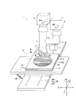
- FIG. 1 is a perspective view showing a schematic configuration of a high-speed imaging apparatus according to an embodiment of the present invention.
- FIG. 2 is a front view showing a main part configuration of the high-speed imaging device, and includes a cross-sectional view in part.
- the high-speed imaging device includes an imaging unit 1, an inspection stage 2, a control unit 3, and the like.
- the imaging unit 1 includes a lens barrel body 4, a first imaging camera 5, a second imaging camera 6, an illumination unit 7, objective lenses 8a, 8b, 8c, a revolver 9, and the like.
- the lens barrel body 4 is branched into two at the top, and a first imaging camera 5 and a second imaging camera 6 are provided in each of the lens barrels.
- a plurality of objective lenses 8 a and 8 b having different magnifications are provided under the lens barrel body 4 via a revolver 9. That is, the imaging field of view can be changed.
- the revolver 9 rotates about the axis P.
- a lighting unit 7 is provided on the side surface of the barrel body 4.
- the light from the irradiation unit 7 is guided to the lower wafer W to the connection portion of the irradiation unit 7 of the lens barrel body 4, and the incident light from the imaging unit 1 is positive from the front surface of the wafer W or the back surface side that has passed through the wafer W.
- a first optical member 10 that totally reflects reflected light (hereinafter referred to as “observation light” as appropriate) is provided.
- the first optical member 10 is, for example, a half mirror or a beam splitter.
- a second optical member 11 that branches the observation light from the wafer W to the first imaging camera 5 and the second imaging camera 6 is provided at a branching portion of the lens barrel body 4. Note that the observation light branched by the second optical member 11 is totally reflected by the reflection mirror 12 and guided to the second imaging camera 6.
- the second optical member 11 may be a half mirror or a beam splitter, for example.
- the first imaging camera 5 and the second imaging camera 6 have the same scan rate.
- line sensors 13a and 13b each having a one-dimensional array of image sensors such as a CCD (charge coupled device) or a CMOS (complementary metal oxide semiconductor) are provided.
- the imaging element digitally converts the luminance value according to the luminance of the observation light and outputs the luminance data.
- the inspection stage 2 includes a holding table 14, a first movable table 15, a second movable table 16, a third movable table 17, and the like.
- the holding table 14 is composed of a porous or metal chuck table that is larger and flatter than the wafer W.
- the three movable platforms provided at the lower part of the holding table 14 are arranged in the order of the first movable table 15, the second movable table 16, and the third movable table 17 from the bottom.
- the first movable base 15 includes a slider 15s that reciprocates in the Y-axis direction along a guide rail 15r laid on the apparatus base 15b.
- the second movable table 16 is composed of a slider 16s that reciprocates in the X-axis direction along a guide rail 16r laid on a base 16b disposed on the slider 15s of the first movable table 15.
- the third movable table 17 is rotated in the ⁇ direction by a motor 18 (for example, a direct drive motor) provided on the slider 16s of the second movable table 16.
- a motor 18 for example, a direct drive motor
- the movement in the X-axis direction is the main scanning direction.
- the Y-axis direction is the direction in which the image sensors of the line sensors 13a and 13b are arranged and is the sub-scanning direction.
- the 1st movable stand 15 and the 2nd movable stand 16 comprise the horizontal drive mechanism of this invention.
- the control unit 3 generally controls the operations of the imaging unit 1 and the inspection stage 2, and includes a storage unit 20 and an arithmetic processing unit 21 therein. Details will be described along the operation description of the high-speed imaging device.
- the moving speed of the slider 16s of the second movable stage 16 that is the main scanning direction of the inspection stage 2 is determined.
- the optimum moving speed V1 is determined by the scan rates of the first imaging camera 5 and the second imaging camera 6. That is, it is determined by the resolution and scan rate of the line sensors 13a and 13b.
- the exposure time for reaching a predetermined resolution is determined in advance by experiments and simulations. For example, when the scan rate of the first imaging camera 5 and the second imaging camera 6 is 10 kHz, one pixel is 10 ⁇ m, and the observation magnification is 10 times, the optimum moving speed of the first imaging camera 5 and the second imaging camera 6 V1 is 10 mm / sec.
- the imaging unit 1 includes the first imaging camera 5 and the second imaging camera 6 before and after the main scanning direction
- the main of the slider 16s of the second movable table 16 is provided.
- the scanning speed V2 is set to 20 mm / sec, which is twice the optimum moving speed V1, and is set so that the imaging by both the imaging cameras 5 and 6 is performed alternately.
- Each of these conditions is stored in the storage unit 20 of the control unit 3.
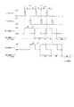
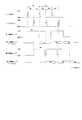
- the exposure times of the first imaging camera 5 and the second imaging camera 6 are set slightly shorter than the scan rate after the division, but an imaging camera capable of adjusting the timing of shuttering is used. Change settings as appropriate within the scan rate. That is, the state in which the shuttering timing is not adjusted is the timing indicated by the broken lines 51 and 61, but the state in which the exposure time is shortened by adjusting the shuttering timing is the timing indicated by the solid lines 52 and 62.
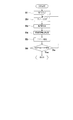
- the wafer W is unloaded from the cassette by a transfer robot or the like, and placed on the holding table 14 as shown in FIG.
- the wafer W is aligned based on an orientation flat or a V notch formed in the outer peripheral region. That is, the first movable table 15 and the second movable table 16 are moved and aligned, and the third movable table 17 is rotated around the rotation axis of the motor 18 to align the wafer W.
- the main scanning speed of the slider 16s of the second movable table 16 is moved after the imaging unit 1 is moved and set to a predetermined height. Imaging of the wafer W is started while scanning V2 in the X-axis direction at twice the optimum moving speed V1.
- the trigger signal 1 is transmitted from the control unit 3 to the first imaging camera 5
- the shutter of the first imaging camera 5 is received and imaging is started. The observation light is exposed to the line sensor 13a.
- the shutter of the second imaging camera 6 is turned on in response thereto, imaging is started, and observation light is exposed to the line sensor 13 b.
- the trigger signal 1 and the trigger signal 2 are alternately output.
- the first imaging camera 5 and the second imaging camera 6 set the shuttering time to half of the normal (that is, the state indicated by the broken lines 51 and 61) (that is, the state indicated by the solid lines 52 and 62). Keep it.
- the first imaging camera 5 and the second imaging camera 6 are generally configured to output image data after the normal shuttering time has elapsed even if the shuttering time is set short. Therefore, after the output signals from both the imaging cameras 5 and 6 are in the OFF state indicated by the broken lines 51 and 61, both the imaging cameras 4 are represented as the luminance data 1a, 1b... And the luminance data 2a, 2b. , 6 are alternately output. By doing so, imaging is performed at an apparently double scan rate using the two imaging cameras 5 and 6 while moving the workpiece at twice the speed.
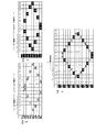
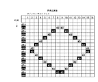
- FIG. 5 shows an image pattern to be imaged, and the luminance value (90) of the image pattern divided into a matrix is shown.
- the blank portion means that the luminance value is zero.
- the vertical axis shows the time of imaging: t0 to t16
- the horizontal axis shows the address (1 to 16) of the line sensor used for imaging.
- timings (t1a to t8a, t1b to t8b) at which the shutters of the first imaging camera 5 and the second imaging camera 6 are turned on are also shown. That is, at time t2, at the address 8 and 9 of the line sensor, the first imaging camera 5 is used to capture 90 luminance portions at the timing t2a when the shutter is turned on.
- the second imaging camera 6 is used to capture 90 luminance portions at the timing t2b when the shutter is turned on.
- the series of continuous imaging processes is defined as one cycle, and the wafer W is imaged by both imaging cameras 5 and 6 while repeating the cycle while scanning from one end of the wafer W to the other end.
- Step S4 Image Reconstruction Processing Processing for performing image reconstruction by performing the above-described series of continuous imaging processing cycles and then image reconstruction will be described.
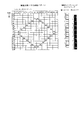
- FIG. 6A shows luminance data output from the first imaging camera 5
- FIG. 6B shows luminance data output from the second imaging camera 6.
- the imaging timing and the data output timing of the first imaging camera 5 and the second imaging camera 6 are alternately performed as shown in FIGS. Therefore, as shown in FIG. 6A, the luminance data is respectively output from the first imaging camera 5 at the data output timings corresponding to the images captured at the timings t1a to t8a when the shutter is turned on (that is, the times d1a to d8a). Is output. Further, as shown in FIG.
- the luminance data is respectively output from the second imaging camera 6 at the data output timing corresponding to the image captured at the timing t1b to t8b when the shutter is turned on (that is, the times d1b to d8b). Is output.
- the signals output from both the imaging cameras 5 and 6 are A / D converted and stored in the storage unit 20 as brightness values separately for each of the first imaging camera 5 and the second imaging camera 6.
- the arithmetic processing unit 21 reads the luminance values of the two imaging cameras 5 and 6 from the storage unit 20, and alternately arranges the read luminance values in order from the oldest one as shown in FIG. Reconstruct the image.
- the luminance value stored in the storage unit 20 is half the original value (45). Therefore, when performing the image reconstruction process, in consideration of this, a process of calculating a value (90) obtained by doubling the luminance value is also performed.
- Step S5 Wafer Unloading
- the wafer W is sucked by a transfer robot or the like and transferred to a cassette (not shown). This completes the process of acquiring a series of inspection images, and thereafter the same process is repeated (step S6).
- the entire surface of the wafer W cannot be continuously imaged by one imaging camera.
- the above-described embodiment apparatus by alternately switching the imaging of the imaging cameras 5 and 6 at the timing when the scan rate is divided into two according to the number of imaging cameras, and further setting the exposure time in half. While the exposure time of each of the first imaging camera 5 and the second imaging camera 6 is halved, continuous image data can be acquired without interruption of the entire wafer image.
- the entire image of the wafer W can be easily reconstructed by simply synthesizing based on the acquired image data (luminance value). That is, since the image of the wafer W can be acquired easily and accurately even at a speed V2 that is twice the optimum moving speed V1 of the imaging camera, the throughput of the inspection process can be increased.
- the present invention is not limited to the embodiment described above, and can be modified as follows.
- Step S3 ′ Imaging Start
- the imaging unit 1 is moved and set to a predetermined height, and then the main scanning of the slider 16s of the second movable table 16 is performed. Imaging of the wafer W is started while scanning the speed V2 in the X-axis direction at twice the optimum moving speed V1.
- the trigger signal 1 is transmitted from the control unit 3 to the first imaging camera 5
- the shutter of the first imaging camera 5 is turned on and imaging is started. The observation light is exposed to the line sensor 13a.
- the shutter of the second imaging camera 6 is turned on in response thereto, imaging is started, and observation light is exposed to the line sensor 13 b.
- the first imaging camera 5 and the second imaging camera 6 have a normal shuttering time (that is, a state indicated by solid lines 53 and 63), and perform imaging while alternately overlapping the same part. .
- imaging is performed at an apparently double scan rate using the two imaging cameras 5 and 6 while moving the workpiece at a double speed.
- FIG. 8 shows an image pattern to be imaged, and the luminance value (90) of the image pattern divided into a matrix is shown.
- the blank portion means that the luminance value is zero.
- the vertical axis shows the time of imaging: t0 to t16, and the horizontal axis shows the address (1 to 16) of the line sensor used for imaging. Further, on the right side of the figure, timings (t1a to t8a, t1b to t8b) at which the shutters of the first imaging camera 5 and the second imaging camera 6 are turned on are also shown.
- the first imaging camera 5 is used to capture 90 luminance portions at the timing t2a when the shutter is turned on.
- the second imaging camera 6 is used to capture the 90 brightness portion at the timing t2b when the shutter is turned on.
- the series of continuous imaging processes is defined as one cycle, and the wafer W is imaged by both imaging cameras 5 and 6 while repeating the cycle while scanning from one end of the wafer W to the other end.
- Step S4 ′ Image Reconstruction Process A process for capturing an image by performing the above-described series of continuous imaging process cycles and then reconstructing the image will be described.
- FIG. 9A shows luminance data output from the first imaging camera 5
- FIG. 9B shows luminance data output from the second imaging camera 6.
- the imaging timing and the data output timing of the first imaging camera 5 and the second imaging camera 6 are alternately performed as shown in FIGS. Therefore, as shown in FIG. 9A, the luminance data is respectively output from the first imaging camera 5 at the data output timings corresponding to the images captured at the timings t1a to t8a when the shutter is turned on (that is, the times d1a to d8a). Is output. Further, as shown in FIG. 9B, the luminance data is respectively output from the second imaging camera 6 at the data output timing corresponding to the image captured at the timing t1b to t8b when the shutter is turned on (that is, the times d1b to d8b). Is output.
- step S4 The signals output from both the imaging cameras 5 and 6 are A / D converted and stored in the storage unit 20 as brightness values separately for each of the first imaging camera 5 and the second imaging camera 6. Since imaging is performed over two pixels for a long time, the two pixels are averaged and the luminance value is stored. Therefore, based on the following procedure, taking into account that the luminance values acquired by the two cameras are averaged in time series and also acquired by the other camera in an overlapping manner. Then, image reconstruction processing is performed (these are different from step S4).
- the first half of exposure when the current imaging camera receiving the trigger signal starts imaging.
- the output signal within the time and the output signal of the second half exposure time of the preceding imaging camera overlap and are output.
- the luminance value obtained based on both output signals is stored in the storage unit 20 as a measured luminance value obtained by combining the luminance values to be acquired in advance.
- addresses 8 and 9 will be described as follows. First, an image captured at time t1a by the first imaging camera 5 is output with a luminance value (B) of 0 at time d1a. Further, the luminance value (C) of this place is set to 0 as the luminance value (A) of the immediately preceding pixel. Therefore, the portion corresponding to the addresses 8 and 9 at the time d1a is calculated as the luminance value 0. Subsequently, the image captured at the time t1b by the second imaging camera 6 is output with a luminance value (B) of 45 at the time d1b. In addition, the luminance value (A) of the immediately preceding pixel is calculated as 0 as the luminance value (C) of this place. Therefore, the portion corresponding to the addresses 8 and 9 at the time d1b is calculated as the luminance value 90.
- the image captured at time t2a by the first imaging camera 5 is output with a luminance value (B) of 45 at time d2a.
- the luminance value (C) of the previous pixel is set to 90 as the luminance value (A) of the immediately preceding pixel. Therefore, the portion corresponding to the addresses 8 and 9 at the time d2a is calculated as the luminance value 0.
- the scanning speed of the imaging camera is not limited, and the optimum moving speed is achieved. It is possible to realize imaging at twice the speed V2 exceeding V1.
- the first imaging camera 5 and the second imaging camera 6 may be configured to include a plurality of line sensors.
- line sensors are arranged adjacently before and after in the main scanning direction, and the luminance value at the same address acquired by each line sensor is subjected to time delay integration processing (so-called TDI (Time Delay Integration) processing).
- TDI Time Delay Integration
- This configuration may be realized by combining a plurality of separate line sensors and a TDI circuit, or a commonly available so-called TDI camera (one in which the above configuration is integrated) may be used.
- the scanning speed of the line sensor itself is the optimum moving speed V1 as in the above embodiment, the luminance values acquired by a plurality of sensors are subjected to time delay integration processing, Sensitivity imaging can be realized. Therefore, when the brightness value of the workpiece is low, it is preferable to inspect using such a camera. However, when the moving speed of the workpiece does not coincide with the optimum moving speed V1, the timing of the time delay integration process does not match and predetermined acquired image data cannot be obtained. Therefore, in the modification according to the present invention, when a TDI camera is used, the following step S3 ′′ is performed instead of the above-described step S3 ′.
- the imaging unit 1 is moved and set to a predetermined height, and then the main scanning of the slider 16s of the second movable table 16 is performed.
- the imaging of the wafer W is started while scanning with the speed V2 set to twice the optimum moving speed V1 in the X-axis direction
- the first imaging camera 5 and the second imaging camera 6 are, for example, main It is configured using a TDI camera provided with four lines of line sensors and a time delay integration processing circuit in the scanning direction.
- the trigger signal 1 and the trigger signal 2 are alternately transmitted from the control unit 3 to the first imaging camera 5 and the second imaging camera 6. deep.
- the first imaging camera 5 and the second imaging camera 6 are configured to perform imaging while alternately overlapping the same part. Then, imaging is performed using the two imaging cameras 5 and 6 while moving the workpiece at the main scanning speed V2.
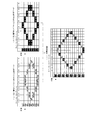
- FIG. 10 shows an image pattern to be imaged, and the luminance value (20) of the image pattern divided into a matrix is shown.
- the blank portion means that the luminance value is zero.
- the vertical axis shows the time of imaging: t0 to t16, and the horizontal axis shows the address (1 to 16) of the line sensor used for imaging.
- the first imaging camera 5 is at the position shown in FIG. 11A at time t3 and at the position shown in FIG. 11B at time t5. Then, the luminance data of the previous stage captured and acquired using the first line sensor group from time t2 to t3 is sent to the subsequent stage by TDI processing, and imaged and acquired using the second line sensor group from time t4 to t5. The subsequent luminance data and integration processing are performed. Then, the integrated value for a predetermined number of steps (two in the above example) is output to the outside as luminance data for one imaging at time d2a.
- an image is constructed based on the output signals of a plurality of times of imaging, as shown in FIG.
- the second imaging camera 6 is attached so as to observe a position shifted by one pixel in the main scanning direction from the imaging position of the first imaging camera 5. Therefore, the second imaging camera 6 observes the position shown in FIG. 12A at time t4 and observes the position shown in FIG. 12B at time t6. Then, the previous luminance data captured and acquired using the first line sensor group from time t3 to t4 is sent to the subsequent stage in the TDI processing, and imaged and acquired using the second line sensor group from time t5 to t6. The subsequent luminance data and integration processing are performed. Then, the integrated values for a predetermined number of steps (two in the above example) are output to the outside as luminance data for one imaging at time d2b. Then, when an image is constructed based on the output signals of a plurality of times of imaging, a portion where luminance values overlap is generated as shown in FIG.
- the arithmetic processing unit 21 can reconstruct a desired whole image by performing the image reconstruction process similar to the modification (1). . Moreover, by performing TDI processing using a plurality of line sensors, it is possible to acquire image data obtained by amplifying the luminance value as shown in FIG.
- a workpiece can be imaged with higher sensitivity than when an imaging unit configured with an imaging camera including a single line sensor is used.
- the relative positional relationship with the holding table 14 for each of the first imaging camera 5 and the second imaging camera 6 is obtained by the sensor or the preliminary imaging of each imaging camera.
- the relative shift amount between the imaging cameras may be obtained, and the image may be corrected according to the shift amount.
- the imaging unit 1 includes the two first imaging cameras 5 and the second imaging camera 6, but the number is not limited thereto. That is, the number of imaging cameras may be two or more.
- the moving speed of the second movable table 16 can be increased every time the number of imaging cameras is increased.
- the optimal moving speed V1 ⁇ the number of imaging cameras is set, and the slider 16s of the second movable base 16 is moved.
- the scan rate is equally divided into the number of the images, the images are alternately captured at the divided timing, and the time until the imaging timing is switched may be set as the exposure time of each imaging camera.
- the number of line sensors arranged in parallel in the main scanning direction and the number of pixels to be binned are appropriately set according to the main scanning speed to be set and the desired sensitivity enhancement. To do.
Landscapes
- General Health & Medical Sciences (AREA)
- Immunology (AREA)
- Physics & Mathematics (AREA)
- Health & Medical Sciences (AREA)
- Life Sciences & Earth Sciences (AREA)
- Chemical & Material Sciences (AREA)
- Analytical Chemistry (AREA)
- Biochemistry (AREA)
- Pathology (AREA)
- General Physics & Mathematics (AREA)
- Engineering & Computer Science (AREA)
- Textile Engineering (AREA)
- Studio Devices (AREA)
- Length Measuring Devices By Optical Means (AREA)
- Investigating Materials By The Use Of Optical Means Adapted For Particular Applications (AREA)
- Multimedia (AREA)
- Signal Processing (AREA)
- Image Input (AREA)
Abstract
Description
ラインセンサを備えた複数台の撮像機からなる撮像ユニットと前記ワークを保持する保持テーブルとを所定の移動速度で相対的に水平移動させながら当該ワークを撮像する撮像過程と、
前記各撮像機から取得した輝度値に基づいてワークの画像を再構成する画像再構成過程を備え、
前記撮像過程は、前記移動速度を撮像機の台数に応じて、ラインセンサの分解能とスキャンレートから決まる最適移動速度よりも速い速度に調整し、
前記撮像機の台数に応じてスキャンレートを均等に分割し、
分割後の当該スキャンレートを撮像機に順番に割当て、各スキャンレートの始点で撮像機のシャッタリングを行うとともに、各スキャンレート内で撮像機の露光時間を調整したサイクルを繰り返しながら前記ワークを撮像する
ことを特徴とする。
前記各撮像機から取得した輝度値に基づいてワークの画像を再構成する画像再構成過程を備え、
前記撮像過程は、前記移動速度を撮像機の台数に応じて、ラインセンサの分解能とスキャンレートから決まる最適移動速度よりも速い速度に調整し、
前記撮像機の台数に応じてスキャンレートを均等に分割し、
分割後の当該スキャンレートを撮像機に順番に割当て、各スキャンレートの始点で撮像機のシャッタリングを行うとともに、分割後のスキャンレートを超えて撮像機の露光時間を終了させ、先行の撮像機と後行の撮像機の露光時間をオーバーラップさせたサイクルを繰り返しながら前記ワークを撮像し、複数画素分にわたって取得された輝度値を撮像機ごとに画素数で平均化した輝度値を記憶部に格納し、
前記画像再構成過程は、記憶部から取得した順に前記輝度値を読み出し、演算時点の画素の輝度値を平均化前の輝度値まで増幅させ、直前に算出した画素の輝度値から現時点の増幅後の輝度値を減算した輝度値に基づいて、ワークの画像を再構成する
ことを特徴とする。
前記各撮像機から取得した輝度値に基づいてワークの画像を再構成する画像再構成過程を備え、
前記撮像過程は、前記移動速度を撮像機のラインセンサに応じて、ラインセンサの分解能とスキャンレートから決まる最適移動速度よりも速い速度に調整し、
前記撮像機の有するライセンサの本数に応じてスキャンレートを均等に分割し、
前記撮像機ごとに分割後のスキャンレートをライセンサに順番に割当て、各スキャンレートの始点でシャッタリングを行うとともに、分割後のスキャンレート内で各ラインセンサへの露光時間を終了させるよう調整したサイクルを繰り返しながら前記ワークを撮像させる過程で、
先行の撮像機と後行の撮像機の撮像タイミングをずらしながら交互に同一部位をオーバーラップさせる撮像サイクルを繰り返しながら前記ワークを撮像し、撮像機ごとに複数本のラインセンサにわたって取得された複数画素分の輝度値を積分遅延回路により1画素分の輝度値として記憶部に格納し、
前記画像再構成過程は、取得した順に前記輝度値を読み出し、演算時点の画素の輝度値を平均化前の輝度値まで増幅させ、直前に算出した画素の輝度値から現時点の増幅後の輝度値を減算した輝度値に基づいて、ワークの画像を再構成する
ことを特徴とする。
検出過程で求めた前記位置関係から撮像機同士の相対的なズレ量を求める演算過程を備え、
画像再構成過程は、演算過程で求まったズレ量に基づいて、取得画像データの位置を補正しながら画像を再構成することが好ましい。
前記ワークを保持する保持テーブルと、
前記保持テーブルに載置されたワークに向けて光を照射する照明ユニットと、
前記ワークを撮像するラインセンサを備えた複数台の撮像機からなる撮像ユニットと、
前記保持テーブルと撮像ユニットを所定の移動速度で相対的に水平移動させる水平駆動機構と、
前記撮像機の台数に応じて、ラインセンサの分解能とスキャンレートから決まる最適移動速度よりも速い移動速度に調整し、スキャンレートを撮像機の台数分に均等に分割し、
分割後の当該スキャンレートを撮像機に順番に割当て、各スキャンレートの始点で撮像機にシャッタリングを行わせるとともに、各スキャンレート内で撮像機の露光時間を調整したサイクルを繰り返しながら複数台の撮像機で前記ワークを撮像させる制御部と、
前記各撮像機によって取得された輝度値に基づいてワークの画像を再構成する演算処理部と、
を備えたことを特徴とする。
前記ワークを保持する保持テーブルと、
前記保持テーブルに載置されたワークに向けて光を照射する照明ユニットと、
前記ワークを撮像するラインセンサを備えた複数台の撮像機からなる撮像ユニットと、
前記保持テーブルと撮像ユニットを所定の移動速度で相対的に水平移動させる水平駆動機構と、
前記撮像機の台数に応じて、ラインセンサの分解能とスキャンレートから決まる最適移動速度よりも速い移動速度に調整し、スキャンレートを撮像機の台数分に均等に分割し、分割後の当該スキャンレートを撮像機に順番に割当て、各スキャンレートの始点で撮像機にシャッタリングを行わせるとともに、分割後のスキャンレートを超えて撮像機の露光時間を終了させ、先行の撮像機と後行の撮像機の露光時間をオーバーラップさせたサイクルを繰り返させながら複数台の撮像機で前記ワークを撮像させ、複数画素分にわたって取得された輝度値を撮像機ごとに画素数で平均化した輝度値を記憶部に格納させる制御部と、
前記記憶部から取得した順に前記輝度値を読み出し、演算時点の画素の輝度値を平均化前の輝度値まで増幅させ、直前に算出した画素の輝度値から現時点の増幅後の輝度値を減算した輝度値に基づいて、ワークの画像を再構成する演算処理部と、
を備えたことを特徴とする。
前記ワークを保持する保持テーブルと、
前記保持テーブルに載置されたワークに向けて光を照射する照明ユニットと、
前記ワークを撮像する同じ複数本のラインセンサを有する複数台の撮像機からなる撮像ユニットと、
前記保持テーブルと撮像ユニットを所定の移動速度で相対的に水平移動させる水平駆動機構と、
前記撮像機のラインセンサに応じて、ラインセンサの分解能とスキャンレートから決まる最適移動速度よりも速い移動速度に調整し、記撮像機の有するライセンサの本数に応じてスキャンレートを均等に分割し、撮像機ごとに分割後のスキャンレートをライセンサに順番に割当て、各スキャンレートの始点でシャッタリングを行うとともに、分割後のスキャンレート内で各ラインセンサへの露光時間を終了させるよう調整したサイクルを繰り返しながら前記ワークを撮像させる過程で、
先行の前記撮像機と後行の前記撮像機の撮像タイミングをずらしながら交互に同一部位をオーバーラップさせる撮像サイクルを繰り返させながら前記ワークを撮像し、撮像機ごとに複数本のラインセンサにわたって取得された複数画素分の輝度値を積分遅延回路により1画素分の輝度値として記憶部に格納させる制御部と、
前記記憶部から取得した順に前記輝度値を読み出し、演算時点の画素の輝度値を平均化前の輝度値まで増幅させ、直前に算出した画素の輝度値から現時点の増幅後の輝度値を減算した輝度値に基づいて、ワークの画像を再構成する演算処理部と、
を備えたことを特徴とする。
前記鏡筒部を導光する光を一部透過させるとともに、角度を変えて一部を反射させて複数台の撮像機に光を導光さる光学部材とから構成する。
制御部は、検出器によって検出された位置情報を記憶する記憶部を備え、
演算処理部は、撮像機ごとに取得された位置情報を前記記憶分から読み出して撮像機同士の相対的なズレ量を求め、当該ズレ量に基づいて取得画像データの位置を補正しながら画像を再構成することが好ましい。
まず、検査ステージ2の主走査方向である第2可動台16のスライダ16sの移動速度を決める。そうすると、第1撮像カメラ5および第2撮像カメラ6のスキャンレートによって最適移動速度V1が決まる。つまり、ラインセンサ13a、13bの分解能とスキャンレートによって決まる。本実施例では、所定の分解能に達する露光時間を予め実験やシミュレーションによって決める。例えば、第1撮像カメラ5と第2撮像カメラ6のスキャンレートが10kHzで、1画素が10μmで、観察倍率を10倍とした場合、第1撮像カメラ5と第2撮像カメラ6の最適移動速度V1は10mm/secとなる。
条件設定が完了すると、搬送ロボットなどによってカセットからウエハWを搬出し、図1に示すように、保持テーブル14に載置する。ウエハWは、外周領域に形成されたオリエンテーションフラットまたはVノッチなどに基づいて位置合わせされる。すなわち、第1可動台15および第2可動台16を移動させて位置合わせするとともに、第3可動台17をモータ18の回転軸周りに回転させてウエハWの位置合わせを行う。
ウエハWのアライメント処理と撮像開始の初期位置への移動が完了すると、撮像ユニット1を所定高さに移動および設定した後に、第2可動台16のスライダ16sの主走査速度V2をX軸方向に最適移動速度V1の2倍の速度で走査させながらウエハWの撮像を開始する。撮像開始と同時に、図4に示すように、制御部3から第1撮像カメラ5にトリガ信号1が送信されると、それを受けて第1撮像カメラ5のシャッターがON状態となり撮像が開始され、観察光がラインセンサ13aに露光される。また、制御部3から第2撮像カメラ6にトリガ信号2が送信されると、それを受けて第2撮像カメラ6のシャッターがON状態となり撮像が開始され、観察光がラインセンサ13bに露光される。このとき、トリガ信号1とトリガ信号2はそれぞれ交互に出力するようにしておく。さらに、第1撮像カメラ5と第2撮像カメラ6は、上述したようにシャッタリング時間を通常(つまり、破線51,61で示す状態)の半分(つまり、実線52,62で示す状態)に設定しておく。
上記一連の連続撮像処理サイクルを行って画像を撮像し、後に画像再構築をする処理について説明する。
ウエハWの撮像が完了すると、搬送ロボットなどによってウエハWを吸着し、図示しないカセットにウエハWを搬送する。以上で一連の検査画像を取得する処理が完了し、以後、同じ処理が繰り返される(ステップS6)。
ウエハWのアライメント処理と撮像開始の初期位置への移動が完了すると、撮像ユニット1を所定高さに移動および設定した後に、第2可動台16のスライダ16sの主走査速度V2をX軸方向に最適移動速度V1の2倍の速度で走査させながらウエハWの撮像を開始する。撮像開始と同時に、図7に示すように、制御部3から第1撮像カメラ5にトリガ信号1が送信されると、それを受けて第1撮像カメラ5のシャッターがON状態となり撮像が開始され、観察光がラインセンサ13aに露光される。また、制御部3から第2撮像カメラ6にトリガ信号2が送信されると、それを受けて第2撮像カメラ6のシャッターがON状態となり撮像が開始され、観察光がラインセンサ13bに露光される。このとき、トリガ信号1とトリガ信号2はそれぞれ交互に出力するようにしておく。なお、第1撮像カメラ5と第2撮像カメラ6は、シャッタリング時間は通常の状態(つまり、実線53,63で示す状態)であり、交互に同一部位をオーバーラップしながら撮像を行っている。また、上記ステップS3と同様に、ワークを2倍の速度で移動させつつ、2台の撮像カメラ5,6を用いて、見かけ上2倍のスキャンレートで撮像が行われる。
上記一連の連続撮像処理サイクルを行って画像を撮像し、後に画像再構築をする処理について説明する。
ウエハWのアライメント処理と撮像開始の初期位置への移動が完了すると、撮像ユニット1を所定高さに移動および設定した後に、第2可動台16のスライダ16sの主走査速度V2をX軸方向に最適移動速度V1の2倍の速度に設定して走査させながらウエハWの撮像を開始する。このとき、第1撮像カメラ5と第2撮像カメラ6は、例えば、主走査方向に4列のラインセンサと時間遅延積分処理回路とを備えたTDIカメラを用いて構成しておく。
2 … 検査ステージ
3 … 制御部
4 … 鏡筒本体
5 … 第1撮像カメラ
6 … 第2撮像カメラ
7 … 照明ユニット
13a… ラインセンサ(第1撮像カメラ用)
13b… ラインセンサ(第2撮像カメラ用)
14 … 保持テーブル
15 … 第1可動台
16 … 第2可動台
17 … 第3可動台
20 … 記憶部
21 … 演算処理部
Claims (9)
- ワークを撮像する高速撮像方法であって、
ラインセンサを備えた複数台の撮像機からなる撮像ユニットと前記ワークを保持する保持テーブルとを所定の移動速度で相対的に水平移動させながら当該ワークを撮像する撮像過程と、
前記各撮像機から取得した輝度値に基づいてワークの画像を再構成する画像再構成過程を備え、
前記撮像過程は、前記移動速度を撮像機の台数に応じて、ラインセンサの分解能とスキャンレートから決まる最適移動速度よりも速い速度に調整し、
前記撮像機の台数に応じてスキャンレートを均等に分割し、
分割後の当該スキャンレートを撮像機に順番に割当て各スキャンレートの始点で撮像機のシャッタリングを行うとともに、各スキャンレート内で撮像機の露光時間を調整したサイクルを繰り返しながら前記ワークを撮像する
ことを特徴とする高速撮像方法。 - ワークを撮像する高速撮像方法であって、
ラインセンサを備えた複数台の撮像機からなる撮像ユニットと前記ワークを保持する保持テーブルとを所定の移動速度で相対的に水平移動させながら当該ワークを撮像する撮像過程と、
前記各撮像機から取得した輝度値に基づいてワークの画像を再構成する画像再構成過程を備え、
前記撮像過程は、前記移動速度を撮像機の台数に応じて、ラインセンサの分解能とスキャンレートから決まる最適移動速度よりも速い速度に調整し、
前記撮像機の台数に応じてスキャンレートを均等に分割し、
分割後の当該スキャンレートを撮像機に順番に割当て、各スキャンレートの始点で撮像機のシャッタリングを行うとともに、分割後のスキャンレートを超えて撮像機の露光時間を終了させ、先行の撮像機と後行の撮像機の露光時間をオーバーラップさせたサイクルを繰り返しながら前記ワークを撮像し、複数画素分にわたって取得された輝度値を撮像機ごとに画素数で平均化した輝度値を記憶部に格納し、
前記画像再構成過程は、記憶部から取得した順に前記輝度値を読み出し、演算時点の画素の輝度値を平均化前の輝度値まで増幅させ、直前に算出した画素の輝度値から現時点の増幅後の輝度値を減算した輝度値に基づいて、ワークの画像を再構成する
ことを特徴とする高速撮像方法。 - ワークを撮像する高速撮像方法であって、
同じ複数本のラインセンサを有する複数台の撮像機を備えた撮像ユニットと前記ワークを保持する保持テーブルとを所定の移動速度で相対的に水平移動させながら当該ワークを撮像する撮像過程と、
前記各撮像機から取得した輝度値に基づいてワークの画像を再構成する画像再構成過程を備え、
前記撮像過程は、前記移動速度を撮像機のラインセンサに応じて、ラインセンサの分解能とスキャンレートから決まる最適移動速度よりも速い速度に調整し、
前記撮像機の有するライセンサの本数に応じてスキャンレートを均等に分割し、
前記撮像機ごとに分割後のスキャンレートをライセンサに順番に割当て、各スキャンレートの始点でシャッタリングを行うとともに、分割後のスキャンレート内で各ラインセンサへの露光時間を終了させるよう調整したサイクルを繰り返しながら前記ワークを撮像させる過程で、
先行の撮像機と後行の撮像機の撮像タイミングをずらしながら交互に同一部位をオーバーラップさせる撮像サイクルを繰り返しながら前記ワークを撮像し、撮像機ごとに複数本のラインセンサにわたって取得された複数画素分の輝度値を積分遅延回路により1画素分の輝度値として記憶部に格納し、
前記画像再構成過程は、取得した順に前記輝度値を読み出し、演算時点の画素の輝度値を平均化前の輝度値まで増幅させ、直前に算出した画素の輝度値から現時点の増幅後の輝度値を減算した輝度値に基づいて、ワークの画像を再構成する
ことを特徴とする高速撮像方法。 - 請求項1ないし請求項3のいずれかに記載の高速撮像方法において、
複数台の前記撮像機ごとに保持テーブルとの相対的な位置関係を検出する検出過程と、
前記検出過程で求めた前記位置関係から撮像機同士の相対的なズレ量を求める演算過程を備え、
前記画像再構成過程は、演算過程で求まったズレ量に基づいて、取得画像データの位置を補正しながら画像を再構成する
ことを特徴とする高速撮像方法。 - ワークを撮像する高速撮像装置であって、
前記ワークを保持する保持テーブルと、
前記保持テーブルに載置されたワークに向けて光を照射する照明ユニットと、
前記ワークを撮像するラインセンサを備えた複数台の撮像機からなる撮像ユニットと、
前記保持テーブルと撮像ユニットを所定の移動速度で相対的に水平移動させる水平駆動機構と、
前記撮像機の台数に応じて、ラインセンサの分解能とスキャンレートから決まる最適移動速度よりも速い移動速度に調整し、スキャンレートを撮像機の台数分に均等に分割し、分割後の当該スキャンレートを撮像機に順番に割当て、各スキャンレートの始点で撮像機にシャッタリングを行わせるとともに、各スキャンレート内で撮像機の露光時間を調整したサイクルを繰り返しながら複数台の撮像機で前記ワークを撮像させる制御部と、
前記各撮像機によって取得された輝度値に基づいてワークの画像を再構成する演算処理部と、
を備えたことを特徴とする高速撮像装置。 - ワークを撮像する高速撮像装置であって、
前記ワークを保持する保持テーブルと、
前記保持テーブルに載置されたワークに向けて光を照射する照明ユニットと、
前記ワークを撮像するラインセンサを備えた複数台の撮像機からなる撮像ユニットと、
前記保持テーブルと撮像ユニットを所定の移動速度で相対的に水平移動させる水平駆動機構と、
前記撮像機の台数に応じて、ラインセンサの分解能とスキャンレートから決まる最適移動速度よりも速い移動速度に調整し、スキャンレートを撮像機の台数分に均等に分割し、分割後の当該スキャンレートを撮像機に順番に割当て、各スキャンレートの始点で撮像機にシャッタリングを行わせるとともに、分割後のスキャンレートを超えて撮像機の露光時間を終了させ、先行の撮像機と後行の撮像機の露光時間をオーバーラップさせたサイクルを繰り返させながら複数台の撮像機で前記ワークを撮像させ、複数画素分にわたって取得された輝度値を撮像機ごとに画素数で平均化した輝度値を記憶部に格納させる制御部と、
前記記憶部から取得した順に前記輝度値を読み出し、演算時点の画素の輝度値を平均化前の輝度値まで増幅させ、直前に算出した画素の輝度値から現時点の増幅後の輝度値を減算した輝度値に基づいて、ワークの画像を再構成する演算処理部と、
を備えたことを特徴とする高速撮像装置。 - ワークを撮像する高速撮像装置であって、
前記ワークを保持する保持テーブルと、
前記保持テーブルに載置されたワークに向けて光を照射する照明ユニットと、
前記ワークを撮像する同じ複数本のラインセンサを有する複数台の撮像機からなる撮像ユニットと、
前記保持テーブルと撮像ユニットを所定の移動速度で相対的に水平移動させる水平駆動機構と、
前記撮像機のラインセンサに応じて、ラインセンサの分解能とスキャンレートから決まる最適移動速度よりも速い移動速度に調整し、記撮像機の有するライセンサの本数に応じてスキャンレートを均等に分割し、撮像機ごとに分割後のスキャンレートをライセンサに順番に割当て、各スキャンレートの始点でシャッタリングを行うとともに、分割後のスキャンレート内で各ラインセンサへの露光時間を終了させるよう調整したサイクルを繰り返しながら前記ワークを撮像させる過程で、
先行の前記撮像機と後行の前記撮像機の撮像タイミングをずらしながら交互に同一部位をオーバーラップさせる撮像サイクルを繰り返させながら前記ワークを撮像し、撮像機ごとに複数本のラインセンサにわたって取得された複数画素分の輝度値を積分遅延回路により1画素分の輝度値として記憶部に格納させる制御部と、
前記記憶部から取得した順に前記輝度値を読み出し、演算時点の画素の輝度値を平均化前の輝度値まで増幅させ、直前に算出した画素の輝度値から現時点の増幅後の輝度値を減算した輝度値に基づいて、ワークの画像を再構成する演算処理部と、
を備えたことを特徴とする高速撮像装置。 - 請求項5ないし請求項7のいずれかに記載の高速撮像装置であって、
前記撮像ユニットは、照明ユニットから照射されてワークで反射した光または当該ワークを透過した光を導光する鏡筒部と、
前記鏡筒部を導光する光を一部透過させるとともに、角度を変えて一部を反射させて複数台の撮像機に光を導光さる光学部材と
を備えたことを特徴とする高速撮像装置。 - 請求項5ないし請求項8のいずれかに記載の高速撮像装置であって、
複数台の前記撮像機ごとに保持テーブルとの相対的な位置を検出する検出器を備え、
前記制御部は、検出器によって検出された位置情報を記憶する記憶部を備え、
前記演算処理部は、撮像機ごとに取得された位置情報を前記記憶分から読み出して撮像機同士の相対的なズレ量を求め、当該ズレ量に基づいて取得画像データの位置を補正しながら画像を再構成する
ことを特徴とする高速撮像装置。
Priority Applications (2)
| Application Number | Priority Date | Filing Date | Title |
|---|---|---|---|
| KR1020157030449A KR102179261B1 (ko) | 2013-03-27 | 2014-02-21 | 고속 촬상 방법 및 고속 촬상 장치 |
| CN201480018385.2A CN105103533B (zh) | 2013-03-27 | 2014-02-21 | 高速摄像方法和高速摄像装置 |
Applications Claiming Priority (2)
| Application Number | Priority Date | Filing Date | Title |
|---|---|---|---|
| JP2013066593A JP6238541B2 (ja) | 2013-03-27 | 2013-03-27 | 高速撮像方法および高速撮像装置 |
| JP2013-066593 | 2013-03-27 |
Publications (1)
| Publication Number | Publication Date |
|---|---|
| WO2014156396A1 true WO2014156396A1 (ja) | 2014-10-02 |
Family
ID=51623397
Family Applications (1)
| Application Number | Title | Priority Date | Filing Date |
|---|---|---|---|
| PCT/JP2014/054103 Ceased WO2014156396A1 (ja) | 2013-03-27 | 2014-02-21 | 高速撮像方法および高速撮像装置 |
Country Status (4)
| Country | Link |
|---|---|
| JP (1) | JP6238541B2 (ja) |
| KR (1) | KR102179261B1 (ja) |
| CN (1) | CN105103533B (ja) |
| WO (1) | WO2014156396A1 (ja) |
Cited By (4)
| Publication number | Priority date | Publication date | Assignee | Title |
|---|---|---|---|---|
| CN114598814A (zh) * | 2022-02-28 | 2022-06-07 | 厦门聚视智创科技有限公司 | 一种多工位线扫相机触发控制系统 |
| CN115908618A (zh) * | 2023-02-28 | 2023-04-04 | 脉冲视觉(北京)科技有限公司 | 基于脉冲数据的重构图像生成方法、装置、设备及介质 |
| CN116481981A (zh) * | 2023-04-28 | 2023-07-25 | 苏州睿仟科技有限公司 | 一种细胞玻片成像系统、方法及计算机设备 |
| CN117232396A (zh) * | 2023-11-15 | 2023-12-15 | 湖南睿图智能科技有限公司 | 一种高速生产线产品质量视觉检测系统及方法 |
Families Citing this family (9)
| Publication number | Priority date | Publication date | Assignee | Title |
|---|---|---|---|---|
| JP7209329B2 (ja) * | 2018-06-28 | 2023-01-20 | 株式会社 システムスクエア | 検査装置 |
| CN111727601A (zh) * | 2018-09-30 | 2020-09-29 | 深圳配天智能技术研究院有限公司 | 图像传感器、获取图像的方法、视觉系统及存储介质 |
| JP2020136361A (ja) * | 2019-02-14 | 2020-08-31 | ファスフォードテクノロジ株式会社 | 実装装置および半導体装置の製造方法 |
| CN111610195A (zh) * | 2019-02-22 | 2020-09-01 | 上海微电子装备(集团)股份有限公司 | 一种缺陷检测装置 |
| CN110388960B (zh) * | 2019-07-05 | 2021-12-14 | 燕山大学 | 用低速相机实现高速运动产品质量检测装置 |
| KR102834462B1 (ko) * | 2019-11-07 | 2025-07-16 | 삼성디스플레이 주식회사 | 결함 검사 장치 및 그 결함 검사 방법 |
| CN111780682B (zh) * | 2019-12-12 | 2024-06-21 | 天目爱视(北京)科技有限公司 | 一种基于伺服电机的3d图像采集控制方法 |
| CN111551556B (zh) * | 2020-05-20 | 2023-09-12 | 上海御微半导体技术有限公司 | 一种缺陷检测装置及缺陷检测方法 |
| JP7648304B2 (ja) * | 2021-05-11 | 2025-03-18 | 東京エレクトロン株式会社 | 基板検査方法及び基板検査装置 |
Citations (8)
| Publication number | Priority date | Publication date | Assignee | Title |
|---|---|---|---|---|
| JPH05260261A (ja) * | 1992-03-10 | 1993-10-08 | Ricoh Co Ltd | 画像読み取り装置 |
| JPH0749301A (ja) * | 1993-08-03 | 1995-02-21 | Toa Medical Electronics Co Ltd | 粒子分析装置 |
| JP2003008300A (ja) * | 2001-06-25 | 2003-01-10 | Yamaha Motor Co Ltd | 部品検査装置及び同装置を搭載した表面実装機 |
| JP2003133224A (ja) * | 2001-10-30 | 2003-05-09 | Canon Inc | 表面位置設定方法、表面位置設定装置及び露光装置 |
| JP2006221514A (ja) * | 2005-02-14 | 2006-08-24 | Canon Inc | 生体認証装置及び画像取得方法 |
| JP2009262161A (ja) * | 2008-04-22 | 2009-11-12 | Olympus Corp | 修正装置、修正方法、制御装置、およびプログラム |
| JP2011149701A (ja) * | 2010-01-19 | 2011-08-04 | Shonai Create Kogyo:Kk | ラインセンサーカメラを用いたx線検査装置 |
| JP2013033419A (ja) * | 2011-08-03 | 2013-02-14 | Yamaha Motor Co Ltd | Tdiセンサ、撮像装置、部品実装装置、部品試験装置および基板検査装置 |
Family Cites Families (2)
| Publication number | Priority date | Publication date | Assignee | Title |
|---|---|---|---|---|
| JP3907560B2 (ja) | 2002-09-04 | 2007-04-18 | 株式会社シーアイエス | 画素ずらし用駆動装置 |
| JP2013228338A (ja) * | 2012-04-27 | 2013-11-07 | Panasonic Corp | 撮像方法 |
-
2013
- 2013-03-27 JP JP2013066593A patent/JP6238541B2/ja active Active
-
2014
- 2014-02-21 KR KR1020157030449A patent/KR102179261B1/ko active Active
- 2014-02-21 CN CN201480018385.2A patent/CN105103533B/zh active Active
- 2014-02-21 WO PCT/JP2014/054103 patent/WO2014156396A1/ja not_active Ceased
Patent Citations (8)
| Publication number | Priority date | Publication date | Assignee | Title |
|---|---|---|---|---|
| JPH05260261A (ja) * | 1992-03-10 | 1993-10-08 | Ricoh Co Ltd | 画像読み取り装置 |
| JPH0749301A (ja) * | 1993-08-03 | 1995-02-21 | Toa Medical Electronics Co Ltd | 粒子分析装置 |
| JP2003008300A (ja) * | 2001-06-25 | 2003-01-10 | Yamaha Motor Co Ltd | 部品検査装置及び同装置を搭載した表面実装機 |
| JP2003133224A (ja) * | 2001-10-30 | 2003-05-09 | Canon Inc | 表面位置設定方法、表面位置設定装置及び露光装置 |
| JP2006221514A (ja) * | 2005-02-14 | 2006-08-24 | Canon Inc | 生体認証装置及び画像取得方法 |
| JP2009262161A (ja) * | 2008-04-22 | 2009-11-12 | Olympus Corp | 修正装置、修正方法、制御装置、およびプログラム |
| JP2011149701A (ja) * | 2010-01-19 | 2011-08-04 | Shonai Create Kogyo:Kk | ラインセンサーカメラを用いたx線検査装置 |
| JP2013033419A (ja) * | 2011-08-03 | 2013-02-14 | Yamaha Motor Co Ltd | Tdiセンサ、撮像装置、部品実装装置、部品試験装置および基板検査装置 |
Cited By (5)
| Publication number | Priority date | Publication date | Assignee | Title |
|---|---|---|---|---|
| CN114598814A (zh) * | 2022-02-28 | 2022-06-07 | 厦门聚视智创科技有限公司 | 一种多工位线扫相机触发控制系统 |
| CN115908618A (zh) * | 2023-02-28 | 2023-04-04 | 脉冲视觉(北京)科技有限公司 | 基于脉冲数据的重构图像生成方法、装置、设备及介质 |
| CN116481981A (zh) * | 2023-04-28 | 2023-07-25 | 苏州睿仟科技有限公司 | 一种细胞玻片成像系统、方法及计算机设备 |
| CN117232396A (zh) * | 2023-11-15 | 2023-12-15 | 湖南睿图智能科技有限公司 | 一种高速生产线产品质量视觉检测系统及方法 |
| CN117232396B (zh) * | 2023-11-15 | 2024-02-06 | 湖南睿图智能科技有限公司 | 一种高速生产线产品质量视觉检测系统及方法 |
Also Published As
| Publication number | Publication date |
|---|---|
| CN105103533B (zh) | 2018-05-25 |
| KR102179261B1 (ko) | 2020-11-16 |
| JP2014192721A (ja) | 2014-10-06 |
| CN105103533A (zh) | 2015-11-25 |
| KR20150135431A (ko) | 2015-12-02 |
| JP6238541B2 (ja) | 2017-11-29 |
Similar Documents
| Publication | Publication Date | Title |
|---|---|---|
| JP6238541B2 (ja) | 高速撮像方法および高速撮像装置 | |
| JP6609113B2 (ja) | 撮像装置及びその制御方法 | |
| JP6537838B2 (ja) | 撮像素子 | |
| JP2015211351A5 (ja) | ||
| JP6362511B2 (ja) | 撮像装置及びその制御方法 | |
| WO2014199685A1 (ja) | 画像取得装置及び画像取得装置のフォーカス方法 | |
| US10455140B2 (en) | Focus detection device and imaging system | |
| JP2017158018A (ja) | 画像処理装置およびその制御方法、撮像装置 | |
| US20170171477A1 (en) | Image capturing apparatus and control method thereof | |
| JP2002076317A (ja) | 固体撮像装置および撮像システム | |
| JP6207293B2 (ja) | 撮像装置、撮像システム、撮像装置の制御方法、プログラム、および、記憶媒体 | |
| WO2016154729A1 (en) | High resolution pathology scanner with improved signal to noise ratio | |
| WO2019188934A1 (ja) | 撮像装置、撮像方法、及びプログラム | |
| CN111983884B (zh) | 芯片内外层取像装置 | |
| JP2008072565A (ja) | 撮像装置及び欠陥画素補正方法 | |
| JP2018056944A (ja) | 撮像装置および撮像素子 | |
| JP2009058382A (ja) | 多重スキャンによる画像取得方法、画像取得装置および試料検査装置 | |
| JP4332906B2 (ja) | ラインセンサカメラ | |
| JP2013130686A (ja) | 撮像装置 | |
| JP2018110299A (ja) | 画像処理方法、画像処理装置、および、撮像装置 | |
| JP2018056945A (ja) | 撮像装置および撮像素子 | |
| WO2015182021A1 (ja) | 撮像制御装置、撮像装置および撮像制御方法 | |
| JP2001016493A (ja) | 多画角カメラ装置 | |
| JP6366341B2 (ja) | 撮像装置 | |
| JP2007310202A (ja) | 共焦点顕微鏡 |
Legal Events
| Date | Code | Title | Description |
|---|---|---|---|
| WWE | Wipo information: entry into national phase |
Ref document number: 201480018385.2 Country of ref document: CN |
|
| 121 | Ep: the epo has been informed by wipo that ep was designated in this application |
Ref document number: 14775009 Country of ref document: EP Kind code of ref document: A1 |
|
| NENP | Non-entry into the national phase |
Ref country code: DE |
|
| ENP | Entry into the national phase |
Ref document number: 20157030449 Country of ref document: KR Kind code of ref document: A |
|
| 122 | Ep: pct application non-entry in european phase |
Ref document number: 14775009 Country of ref document: EP Kind code of ref document: A1 |