WO2014156183A1 - 酸性ガス分離用複合体の製造方法および製造装置 - Google Patents
酸性ガス分離用複合体の製造方法および製造装置 Download PDFInfo
- Publication number
- WO2014156183A1 WO2014156183A1 PCT/JP2014/001824 JP2014001824W WO2014156183A1 WO 2014156183 A1 WO2014156183 A1 WO 2014156183A1 JP 2014001824 W JP2014001824 W JP 2014001824W WO 2014156183 A1 WO2014156183 A1 WO 2014156183A1
- Authority
- WO
- WIPO (PCT)
- Prior art keywords
- acidic gas
- humidity
- gas separation
- film
- roll
- Prior art date
Links
- 238000000926 separation method Methods 0.000 title claims abstract description 160
- 238000004519 manufacturing process Methods 0.000 title claims abstract description 67
- 239000002253 acid Substances 0.000 title abstract description 45
- 238000000576 coating method Methods 0.000 claims abstract description 146
- 239000011248 coating agent Substances 0.000 claims abstract description 130
- 238000001035 drying Methods 0.000 claims abstract description 101
- 238000004804 winding Methods 0.000 claims abstract description 95
- 239000012528 membrane Substances 0.000 claims abstract description 90
- 239000007788 liquid Substances 0.000 claims abstract description 82
- 238000000034 method Methods 0.000 claims abstract description 66
- 230000008569 process Effects 0.000 claims abstract description 53
- XLYOFNOQVPJJNP-UHFFFAOYSA-N water Substances O XLYOFNOQVPJJNP-UHFFFAOYSA-N 0.000 claims abstract description 43
- 150000002433 hydrophilic molecules Chemical class 0.000 claims abstract description 15
- 239000002994 raw material Substances 0.000 claims abstract description 10
- 230000002378 acidificating effect Effects 0.000 claims description 162
- 230000001737 promoting effect Effects 0.000 claims description 24
- 239000002131 composite material Substances 0.000 claims description 18
- 229920002554 vinyl polymer Polymers 0.000 claims description 13
- 230000002209 hydrophobic effect Effects 0.000 claims description 10
- 229910000288 alkali metal carbonate Inorganic materials 0.000 claims description 8
- 150000008041 alkali metal carbonates Chemical class 0.000 claims description 8
- 229920002125 Sokalan® Polymers 0.000 claims description 7
- 239000004745 nonwoven fabric Substances 0.000 claims description 7
- 150000001875 compounds Chemical class 0.000 claims description 6
- 239000004584 polyacrylic acid Substances 0.000 claims description 5
- 238000005096 rolling process Methods 0.000 claims description 5
- 230000015572 biosynthetic process Effects 0.000 abstract description 2
- 239000007789 gas Substances 0.000 description 236
- 239000010408 film Substances 0.000 description 126
- CURLTUGMZLYLDI-UHFFFAOYSA-N Carbon dioxide Chemical compound O=C=O CURLTUGMZLYLDI-UHFFFAOYSA-N 0.000 description 96
- 230000032258 transport Effects 0.000 description 74
- 239000001569 carbon dioxide Substances 0.000 description 48
- 229910002092 carbon dioxide Inorganic materials 0.000 description 48
- 239000000243 solution Substances 0.000 description 41
- -1 polyelenimines Polymers 0.000 description 28
- 229920001477 hydrophilic polymer Polymers 0.000 description 26
- 239000000463 material Substances 0.000 description 17
- 239000010410 layer Substances 0.000 description 16
- 238000005259 measurement Methods 0.000 description 15
- 239000004810 polytetrafluoroethylene Substances 0.000 description 15
- 229920001343 polytetrafluoroethylene Polymers 0.000 description 15
- 238000010521 absorption reaction Methods 0.000 description 13
- 230000007547 defect Effects 0.000 description 13
- 238000004132 cross linking Methods 0.000 description 12
- 239000012466 permeate Substances 0.000 description 12
- 239000007864 aqueous solution Substances 0.000 description 11
- 238000011156 evaluation Methods 0.000 description 11
- 239000000203 mixture Substances 0.000 description 11
- RTZKZFJDLAIYFH-UHFFFAOYSA-N Diethyl ether Chemical compound CCOCC RTZKZFJDLAIYFH-UHFFFAOYSA-N 0.000 description 10
- UGFAIRIUMAVXCW-UHFFFAOYSA-N Carbon monoxide Chemical compound [O+]#[C-] UGFAIRIUMAVXCW-UHFFFAOYSA-N 0.000 description 9
- 229910002091 carbon monoxide Inorganic materials 0.000 description 9
- 230000000052 comparative effect Effects 0.000 description 9
- 239000000126 substance Substances 0.000 description 9
- 239000002562 thickening agent Substances 0.000 description 9
- 229920002492 poly(sulfone) Polymers 0.000 description 8
- 239000004743 Polypropylene Substances 0.000 description 7
- 239000003431 cross linking reagent Substances 0.000 description 7
- 229920000058 polyacrylate Polymers 0.000 description 7
- 229920001155 polypropylene Polymers 0.000 description 7
- 239000004642 Polyimide Substances 0.000 description 6
- 229910052783 alkali metal Inorganic materials 0.000 description 6
- 229920001577 copolymer Polymers 0.000 description 6
- 229920001721 polyimide Polymers 0.000 description 6
- 229920002134 Carboxymethyl cellulose Polymers 0.000 description 5
- PEDCQBHIVMGVHV-UHFFFAOYSA-N Glycerine Chemical compound OCC(O)CO PEDCQBHIVMGVHV-UHFFFAOYSA-N 0.000 description 5
- 239000001768 carboxy methyl cellulose Substances 0.000 description 5
- 235000010948 carboxy methyl cellulose Nutrition 0.000 description 5
- 239000008112 carboxymethyl-cellulose Substances 0.000 description 5
- 239000000919 ceramic Substances 0.000 description 5
- 230000007423 decrease Effects 0.000 description 5
- 238000009792 diffusion process Methods 0.000 description 5
- 230000000694 effects Effects 0.000 description 5
- 108010025899 gelatin film Proteins 0.000 description 5
- 239000003349 gelling agent Substances 0.000 description 5
- 238000010438 heat treatment Methods 0.000 description 5
- 229920000728 polyester Polymers 0.000 description 5
- 229920000098 polyolefin Polymers 0.000 description 5
- 239000004952 Polyamide Substances 0.000 description 4
- 238000004378 air conditioning Methods 0.000 description 4
- 150000001412 amines Chemical class 0.000 description 4
- 229920002678 cellulose Polymers 0.000 description 4
- 235000010980 cellulose Nutrition 0.000 description 4
- 238000011109 contamination Methods 0.000 description 4
- 239000011521 glass Substances 0.000 description 4
- 229910052751 metal Inorganic materials 0.000 description 4
- 239000002184 metal Substances 0.000 description 4
- 229920002647 polyamide Polymers 0.000 description 4
- BWHMMNNQKKPAPP-UHFFFAOYSA-L potassium carbonate Chemical compound [K+].[K+].[O-]C([O-])=O BWHMMNNQKKPAPP-UHFFFAOYSA-L 0.000 description 4
- 238000002360 preparation method Methods 0.000 description 4
- 239000011347 resin Substances 0.000 description 4
- 229920005989 resin Polymers 0.000 description 4
- HZAXFHJVJLSVMW-UHFFFAOYSA-N 2-Aminoethan-1-ol Chemical compound NCCO HZAXFHJVJLSVMW-UHFFFAOYSA-N 0.000 description 3
- 229920001817 Agar Polymers 0.000 description 3
- LYCAIKOWRPUZTN-UHFFFAOYSA-N Ethylene glycol Chemical compound OCCO LYCAIKOWRPUZTN-UHFFFAOYSA-N 0.000 description 3
- SXRSQZLOMIGNAQ-UHFFFAOYSA-N Glutaraldehyde Chemical compound O=CCCCC=O SXRSQZLOMIGNAQ-UHFFFAOYSA-N 0.000 description 3
- WMFOQBRAJBCJND-UHFFFAOYSA-M Lithium hydroxide Chemical compound [Li+].[OH-] WMFOQBRAJBCJND-UHFFFAOYSA-M 0.000 description 3
- 239000002033 PVDF binder Substances 0.000 description 3
- 239000004697 Polyetherimide Substances 0.000 description 3
- 239000004734 Polyphenylene sulfide Substances 0.000 description 3
- KWYUFKZDYYNOTN-UHFFFAOYSA-M Potassium hydroxide Chemical compound [OH-].[K+] KWYUFKZDYYNOTN-UHFFFAOYSA-M 0.000 description 3
- DNIAPMSPPWPWGF-UHFFFAOYSA-N Propylene glycol Chemical compound CC(O)CO DNIAPMSPPWPWGF-UHFFFAOYSA-N 0.000 description 3
- HEMHJVSKTPXQMS-UHFFFAOYSA-M Sodium hydroxide Chemical compound [OH-].[Na+] HEMHJVSKTPXQMS-UHFFFAOYSA-M 0.000 description 3
- 239000008272 agar Substances 0.000 description 3
- 235000010419 agar Nutrition 0.000 description 3
- 150000001339 alkali metal compounds Chemical class 0.000 description 3
- 150000001340 alkali metals Chemical class 0.000 description 3
- 239000004760 aramid Substances 0.000 description 3
- 229920003235 aromatic polyamide Polymers 0.000 description 3
- 230000000903 blocking effect Effects 0.000 description 3
- FJDQFPXHSGXQBY-UHFFFAOYSA-L caesium carbonate Chemical compound [Cs+].[Cs+].[O-]C([O-])=O FJDQFPXHSGXQBY-UHFFFAOYSA-L 0.000 description 3
- 229910000024 caesium carbonate Inorganic materials 0.000 description 3
- 239000001913 cellulose Substances 0.000 description 3
- 239000003795 chemical substances by application Substances 0.000 description 3
- 238000001816 cooling Methods 0.000 description 3
- MTHSVFCYNBDYFN-UHFFFAOYSA-N diethylene glycol Chemical compound OCCOCCO MTHSVFCYNBDYFN-UHFFFAOYSA-N 0.000 description 3
- GYZLOYUZLJXAJU-UHFFFAOYSA-N diglycidyl ether Chemical compound C1OC1COCC1CO1 GYZLOYUZLJXAJU-UHFFFAOYSA-N 0.000 description 3
- 238000004090 dissolution Methods 0.000 description 3
- 239000001257 hydrogen Substances 0.000 description 3
- 229910052739 hydrogen Inorganic materials 0.000 description 3
- RAXXELZNTBOGNW-UHFFFAOYSA-N imidazole Natural products C1=CNC=N1 RAXXELZNTBOGNW-UHFFFAOYSA-N 0.000 description 3
- 238000010030 laminating Methods 0.000 description 3
- 239000004417 polycarbonate Substances 0.000 description 3
- 229920000515 polycarbonate Polymers 0.000 description 3
- 229920001601 polyetherimide Polymers 0.000 description 3
- 229920000069 polyphenylene sulfide Polymers 0.000 description 3
- 229920002981 polyvinylidene fluoride Polymers 0.000 description 3
- 238000005185 salting out Methods 0.000 description 3
- 239000002904 solvent Substances 0.000 description 3
- 125000000391 vinyl group Chemical group [H]C([*])=C([H])[H] 0.000 description 3
- JYEUMXHLPRZUAT-UHFFFAOYSA-N 1,2,3-triazine Chemical compound C1=CN=NN=C1 JYEUMXHLPRZUAT-UHFFFAOYSA-N 0.000 description 2
- NLMDJJTUQPXZFG-UHFFFAOYSA-N 1,4,10,13-tetraoxa-7,16-diazacyclooctadecane Chemical compound C1COCCOCCNCCOCCOCCN1 NLMDJJTUQPXZFG-UHFFFAOYSA-N 0.000 description 2
- AOBIOSPNXBMOAT-UHFFFAOYSA-N 2-[2-(oxiran-2-ylmethoxy)ethoxymethyl]oxirane Chemical compound C1OC1COCCOCC1CO1 AOBIOSPNXBMOAT-UHFFFAOYSA-N 0.000 description 2
- NOWKCMXCCJGMRR-UHFFFAOYSA-N Aziridine Chemical compound C1CN1 NOWKCMXCCJGMRR-UHFFFAOYSA-N 0.000 description 2
- DHMQDGOQFOQNFH-UHFFFAOYSA-N Glycine Chemical compound NCC(O)=O DHMQDGOQFOQNFH-UHFFFAOYSA-N 0.000 description 2
- UFHFLCQGNIYNRP-UHFFFAOYSA-N Hydrogen Chemical compound [H][H] UFHFLCQGNIYNRP-UHFFFAOYSA-N 0.000 description 2
- HNDVDQJCIGZPNO-YFKPBYRVSA-N L-histidine Chemical compound OC(=O)[C@@H](N)CC1=CN=CN1 HNDVDQJCIGZPNO-YFKPBYRVSA-N 0.000 description 2
- GLUUGHFHXGJENI-UHFFFAOYSA-N Piperazine Chemical compound C1CNCCN1 GLUUGHFHXGJENI-UHFFFAOYSA-N 0.000 description 2
- 239000004696 Poly ether ether ketone Substances 0.000 description 2
- 239000004695 Polyether sulfone Substances 0.000 description 2
- 239000004698 Polyethylene Substances 0.000 description 2
- 239000002202 Polyethylene glycol Substances 0.000 description 2
- 239000004793 Polystyrene Substances 0.000 description 2
- ZLMJMSJWJFRBEC-UHFFFAOYSA-N Potassium Chemical compound [K] ZLMJMSJWJFRBEC-UHFFFAOYSA-N 0.000 description 2
- JUJWROOIHBZHMG-UHFFFAOYSA-N Pyridine Chemical compound C1=CC=NC=C1 JUJWROOIHBZHMG-UHFFFAOYSA-N 0.000 description 2
- CDBYLPFSWZWCQE-UHFFFAOYSA-L Sodium Carbonate Chemical compound [Na+].[Na+].[O-]C([O-])=O CDBYLPFSWZWCQE-UHFFFAOYSA-L 0.000 description 2
- UIIMBOGNXHQVGW-UHFFFAOYSA-M Sodium bicarbonate Chemical compound [Na+].OC([O-])=O UIIMBOGNXHQVGW-UHFFFAOYSA-M 0.000 description 2
- 239000000654 additive Substances 0.000 description 2
- 238000013019 agitation Methods 0.000 description 2
- 150000001299 aldehydes Chemical class 0.000 description 2
- 150000008044 alkali metal hydroxides Chemical class 0.000 description 2
- 235000001014 amino acid Nutrition 0.000 description 2
- 150000001413 amino acids Chemical class 0.000 description 2
- 150000003863 ammonium salts Chemical class 0.000 description 2
- 150000007514 bases Chemical class 0.000 description 2
- 239000011230 binding agent Substances 0.000 description 2
- 229910052792 caesium Inorganic materials 0.000 description 2
- TVFDJXOCXUVLDH-UHFFFAOYSA-N caesium atom Chemical compound [Cs] TVFDJXOCXUVLDH-UHFFFAOYSA-N 0.000 description 2
- 239000011247 coating layer Substances 0.000 description 2
- 238000005336 cracking Methods 0.000 description 2
- 230000003247 decreasing effect Effects 0.000 description 2
- 238000011161 development Methods 0.000 description 2
- 238000010586 diagram Methods 0.000 description 2
- ZBCBWPMODOFKDW-UHFFFAOYSA-N diethanolamine Chemical compound OCCNCCO ZBCBWPMODOFKDW-UHFFFAOYSA-N 0.000 description 2
- 238000010894 electron beam technology Methods 0.000 description 2
- 238000005516 engineering process Methods 0.000 description 2
- 239000000499 gel Substances 0.000 description 2
- 235000011187 glycerol Nutrition 0.000 description 2
- LEQAOMBKQFMDFZ-UHFFFAOYSA-N glyoxal Chemical compound O=CC=O LEQAOMBKQFMDFZ-UHFFFAOYSA-N 0.000 description 2
- HNDVDQJCIGZPNO-UHFFFAOYSA-N histidine Natural products OC(=O)C(N)CC1=CN=CN1 HNDVDQJCIGZPNO-UHFFFAOYSA-N 0.000 description 2
- 239000000017 hydrogel Substances 0.000 description 2
- 229910010272 inorganic material Inorganic materials 0.000 description 2
- 239000011147 inorganic material Substances 0.000 description 2
- 238000009434 installation Methods 0.000 description 2
- 239000012948 isocyanate Substances 0.000 description 2
- 150000002513 isocyanates Chemical class 0.000 description 2
- 238000002844 melting Methods 0.000 description 2
- 230000008018 melting Effects 0.000 description 2
- QJGQUHMNIGDVPM-UHFFFAOYSA-N nitrogen group Chemical group [N] QJGQUHMNIGDVPM-UHFFFAOYSA-N 0.000 description 2
- WXZMFSXDPGVJKK-UHFFFAOYSA-N pentaerythritol Chemical compound OCC(CO)(CO)CO WXZMFSXDPGVJKK-UHFFFAOYSA-N 0.000 description 2
- 230000035699 permeability Effects 0.000 description 2
- 229920006393 polyether sulfone Polymers 0.000 description 2
- 229920002530 polyetherether ketone Polymers 0.000 description 2
- 229920000573 polyethylene Polymers 0.000 description 2
- 229920001223 polyethylene glycol Polymers 0.000 description 2
- 229920000139 polyethylene terephthalate Polymers 0.000 description 2
- 239000005020 polyethylene terephthalate Substances 0.000 description 2
- 229920000642 polymer Polymers 0.000 description 2
- 229920002223 polystyrene Polymers 0.000 description 2
- 229910052700 potassium Inorganic materials 0.000 description 2
- 229960003975 potassium Drugs 0.000 description 2
- 239000011591 potassium Substances 0.000 description 2
- 229910000027 potassium carbonate Inorganic materials 0.000 description 2
- 235000011181 potassium carbonates Nutrition 0.000 description 2
- 230000002265 prevention Effects 0.000 description 2
- 230000002441 reversible effect Effects 0.000 description 2
- 229910052701 rubidium Inorganic materials 0.000 description 2
- IGLNJRXAVVLDKE-UHFFFAOYSA-N rubidium atom Chemical compound [Rb] IGLNJRXAVVLDKE-UHFFFAOYSA-N 0.000 description 2
- CPRMKOQKXYSDML-UHFFFAOYSA-M rubidium hydroxide Chemical compound [OH-].[Rb+] CPRMKOQKXYSDML-UHFFFAOYSA-M 0.000 description 2
- 150000003839 salts Chemical class 0.000 description 2
- 159000000000 sodium salts Chemical class 0.000 description 2
- 238000001179 sorption measurement Methods 0.000 description 2
- 125000006850 spacer group Chemical group 0.000 description 2
- 229910001220 stainless steel Inorganic materials 0.000 description 2
- 239000010935 stainless steel Substances 0.000 description 2
- 150000005846 sugar alcohols Polymers 0.000 description 2
- XOAAWQZATWQOTB-UHFFFAOYSA-N taurine Chemical compound NCCS(O)(=O)=O XOAAWQZATWQOTB-UHFFFAOYSA-N 0.000 description 2
- 238000012360 testing method Methods 0.000 description 2
- 239000010409 thin film Substances 0.000 description 2
- 230000000007 visual effect Effects 0.000 description 2
- 239000002759 woven fabric Substances 0.000 description 2
- 230000037303 wrinkles Effects 0.000 description 2
- MTCFGRXMJLQNBG-REOHCLBHSA-N (2S)-2-Amino-3-hydroxypropansäure Chemical compound OC[C@H](N)C(O)=O MTCFGRXMJLQNBG-REOHCLBHSA-N 0.000 description 1
- UWFRVQVNYNPBEF-UHFFFAOYSA-N 1-(2,4-dimethylphenyl)propan-1-one Chemical compound CCC(=O)C1=CC=C(C)C=C1C UWFRVQVNYNPBEF-UHFFFAOYSA-N 0.000 description 1
- LHXNVCCLDTYJGT-UHFFFAOYSA-N 1-(oxiran-2-ylmethoxy)propan-2-ol Chemical compound CC(O)COCC1CO1 LHXNVCCLDTYJGT-UHFFFAOYSA-N 0.000 description 1
- VILCJCGEZXAXTO-UHFFFAOYSA-N 2,2,2-tetramine Chemical compound NCCNCCNCCN VILCJCGEZXAXTO-UHFFFAOYSA-N 0.000 description 1
- MFGOFGRYDNHJTA-UHFFFAOYSA-N 2-amino-1-(2-fluorophenyl)ethanol Chemical compound NCC(O)C1=CC=CC=C1F MFGOFGRYDNHJTA-UHFFFAOYSA-N 0.000 description 1
- AUFVJZSDSXXFOI-UHFFFAOYSA-N 2.2.2-cryptand Chemical compound C1COCCOCCN2CCOCCOCCN1CCOCCOCC2 AUFVJZSDSXXFOI-UHFFFAOYSA-N 0.000 description 1
- PECYZEOJVXMISF-UHFFFAOYSA-N 3-aminoalanine Chemical compound [NH3+]CC(N)C([O-])=O PECYZEOJVXMISF-UHFFFAOYSA-N 0.000 description 1
- 229920002101 Chitin Polymers 0.000 description 1
- FBPFZTCFMRRESA-FSIIMWSLSA-N D-Glucitol Natural products OC[C@H](O)[C@H](O)[C@@H](O)[C@H](O)CO FBPFZTCFMRRESA-FSIIMWSLSA-N 0.000 description 1
- FBPFZTCFMRRESA-JGWLITMVSA-N D-glucitol Chemical compound OC[C@H](O)[C@@H](O)[C@H](O)[C@H](O)CO FBPFZTCFMRRESA-JGWLITMVSA-N 0.000 description 1
- RPNUMPOLZDHAAY-UHFFFAOYSA-N Diethylenetriamine Chemical compound NCCNCCN RPNUMPOLZDHAAY-UHFFFAOYSA-N 0.000 description 1
- KCXVZYZYPLLWCC-UHFFFAOYSA-N EDTA Chemical compound OC(=O)CN(CC(O)=O)CCN(CC(O)=O)CC(O)=O KCXVZYZYPLLWCC-UHFFFAOYSA-N 0.000 description 1
- BRLQWZUYTZBJKN-UHFFFAOYSA-N Epichlorohydrin Chemical compound ClCC1CO1 BRLQWZUYTZBJKN-UHFFFAOYSA-N 0.000 description 1
- PIICEJLVQHRZGT-UHFFFAOYSA-N Ethylenediamine Chemical compound NCCN PIICEJLVQHRZGT-UHFFFAOYSA-N 0.000 description 1
- 239000004471 Glycine Substances 0.000 description 1
- 229920002907 Guar gum Polymers 0.000 description 1
- 239000005057 Hexamethylene diisocyanate Substances 0.000 description 1
- 239000004705 High-molecular-weight polyethylene Substances 0.000 description 1
- 241000899793 Hypsophrys nicaraguensis Species 0.000 description 1
- DGAQECJNVWCQMB-PUAWFVPOSA-M Ilexoside XXIX Chemical compound C[C@@H]1CC[C@@]2(CC[C@@]3(C(=CC[C@H]4[C@]3(CC[C@@H]5[C@@]4(CC[C@@H](C5(C)C)OS(=O)(=O)[O-])C)C)[C@@H]2[C@]1(C)O)C)C(=O)O[C@H]6[C@@H]([C@H]([C@@H]([C@H](O6)CO)O)O)O.[Na+] DGAQECJNVWCQMB-PUAWFVPOSA-M 0.000 description 1
- 238000012695 Interfacial polymerization Methods 0.000 description 1
- XUJNEKJLAYXESH-REOHCLBHSA-N L-Cysteine Chemical compound SC[C@H](N)C(O)=O XUJNEKJLAYXESH-REOHCLBHSA-N 0.000 description 1
- ONIBWKKTOPOVIA-BYPYZUCNSA-N L-Proline Chemical compound OC(=O)[C@@H]1CCCN1 ONIBWKKTOPOVIA-BYPYZUCNSA-N 0.000 description 1
- QNAYBMKLOCPYGJ-REOHCLBHSA-N L-alanine Chemical compound C[C@H](N)C(O)=O QNAYBMKLOCPYGJ-REOHCLBHSA-N 0.000 description 1
- LEVWYRKDKASIDU-IMJSIDKUSA-N L-cystine Chemical compound [O-]C(=O)[C@@H]([NH3+])CSSC[C@H]([NH3+])C([O-])=O LEVWYRKDKASIDU-IMJSIDKUSA-N 0.000 description 1
- WHXSMMKQMYFTQS-UHFFFAOYSA-N Lithium Chemical compound [Li] WHXSMMKQMYFTQS-UHFFFAOYSA-N 0.000 description 1
- 229920003171 Poly (ethylene oxide) Polymers 0.000 description 1
- 229920001145 Poly(N-vinylacetamide) Polymers 0.000 description 1
- 229920012266 Poly(ether sulfone) PES Polymers 0.000 description 1
- 229920002873 Polyethylenimine Polymers 0.000 description 1
- ONIBWKKTOPOVIA-UHFFFAOYSA-N Proline Natural products OC(=O)C1CCCN1 ONIBWKKTOPOVIA-UHFFFAOYSA-N 0.000 description 1
- XBDQKXXYIPTUBI-UHFFFAOYSA-M Propionate Chemical compound CCC([O-])=O XBDQKXXYIPTUBI-UHFFFAOYSA-M 0.000 description 1
- MTCFGRXMJLQNBG-UHFFFAOYSA-N Serine Natural products OCC(N)C(O)=O MTCFGRXMJLQNBG-UHFFFAOYSA-N 0.000 description 1
- 229920002472 Starch Polymers 0.000 description 1
- UCKMPCXJQFINFW-UHFFFAOYSA-N Sulphide Chemical compound [S-2] UCKMPCXJQFINFW-UHFFFAOYSA-N 0.000 description 1
- UWHCKJMYHZGTIT-UHFFFAOYSA-N Tetraethylene glycol, Natural products OCCOCCOCCOCCO UWHCKJMYHZGTIT-UHFFFAOYSA-N 0.000 description 1
- GSEJCLTVZPLZKY-UHFFFAOYSA-N Triethanolamine Chemical compound OCCN(CCO)CCO GSEJCLTVZPLZKY-UHFFFAOYSA-N 0.000 description 1
- 239000007983 Tris buffer Substances 0.000 description 1
- 150000007513 acids Chemical class 0.000 description 1
- 230000002411 adverse Effects 0.000 description 1
- 235000004279 alanine Nutrition 0.000 description 1
- 229920000615 alginic acid Polymers 0.000 description 1
- 235000010443 alginic acid Nutrition 0.000 description 1
- 150000004781 alginic acids Chemical class 0.000 description 1
- 239000012298 atmosphere Substances 0.000 description 1
- 238000007611 bar coating method Methods 0.000 description 1
- 230000005540 biological transmission Effects 0.000 description 1
- 238000007664 blowing Methods 0.000 description 1
- ZMCUDHNSHCRDBT-UHFFFAOYSA-M caesium bicarbonate Chemical compound [Cs+].OC([O-])=O ZMCUDHNSHCRDBT-UHFFFAOYSA-M 0.000 description 1
- HUCVOHYBFXVBRW-UHFFFAOYSA-M caesium hydroxide Inorganic materials [OH-].[Cs+] HUCVOHYBFXVBRW-UHFFFAOYSA-M 0.000 description 1
- 238000004364 calculation method Methods 0.000 description 1
- 229910052799 carbon Inorganic materials 0.000 description 1
- 235000010418 carrageenan Nutrition 0.000 description 1
- 239000000679 carrageenan Substances 0.000 description 1
- 229920001525 carrageenan Polymers 0.000 description 1
- 229940113118 carrageenan Drugs 0.000 description 1
- 239000000969 carrier Substances 0.000 description 1
- 239000003054 catalyst Substances 0.000 description 1
- 230000008859 change Effects 0.000 description 1
- 239000002739 cryptand Substances 0.000 description 1
- 238000007766 curtain coating Methods 0.000 description 1
- 238000005520 cutting process Methods 0.000 description 1
- 125000004122 cyclic group Chemical group 0.000 description 1
- 235000018417 cysteine Nutrition 0.000 description 1
- XUJNEKJLAYXESH-UHFFFAOYSA-N cysteine Natural products SCC(N)C(O)=O XUJNEKJLAYXESH-UHFFFAOYSA-N 0.000 description 1
- 229960003067 cystine Drugs 0.000 description 1
- 238000007791 dehumidification Methods 0.000 description 1
- 238000013461 design Methods 0.000 description 1
- 230000006866 deterioration Effects 0.000 description 1
- GPLRAVKSCUXZTP-UHFFFAOYSA-N diglycerol Chemical compound OCC(O)COCC(O)CO GPLRAVKSCUXZTP-UHFFFAOYSA-N 0.000 description 1
- 238000003618 dip coating Methods 0.000 description 1
- 238000009826 distribution Methods 0.000 description 1
- WNAHIZMDSQCWRP-UHFFFAOYSA-N dodecane-1-thiol Chemical compound CCCCCCCCCCCCS WNAHIZMDSQCWRP-UHFFFAOYSA-N 0.000 description 1
- 238000005265 energy consumption Methods 0.000 description 1
- 230000007613 environmental effect Effects 0.000 description 1
- 238000006266 etherification reaction Methods 0.000 description 1
- 230000001747 exhibiting effect Effects 0.000 description 1
- 238000007765 extrusion coating Methods 0.000 description 1
- 235000019000 fluorine Nutrition 0.000 description 1
- 150000002222 fluorine compounds Chemical class 0.000 description 1
- 125000001153 fluoro group Chemical group F* 0.000 description 1
- 239000000446 fuel Substances 0.000 description 1
- 125000000524 functional group Chemical group 0.000 description 1
- 229940015043 glyoxal Drugs 0.000 description 1
- 239000000665 guar gum Substances 0.000 description 1
- 235000010417 guar gum Nutrition 0.000 description 1
- 229960002154 guar gum Drugs 0.000 description 1
- 229920000591 gum Polymers 0.000 description 1
- 125000005842 heteroatom Chemical group 0.000 description 1
- RRAMGCGOFNQTLD-UHFFFAOYSA-N hexamethylene diisocyanate Chemical compound O=C=NCCCCCCN=C=O RRAMGCGOFNQTLD-UHFFFAOYSA-N 0.000 description 1
- 229930195733 hydrocarbon Natural products 0.000 description 1
- 150000002430 hydrocarbons Chemical class 0.000 description 1
- 150000002431 hydrogen Chemical class 0.000 description 1
- KEDRKJFXBSLXSI-UHFFFAOYSA-M hydron;rubidium(1+);carbonate Chemical compound [Rb+].OC([O-])=O KEDRKJFXBSLXSI-UHFFFAOYSA-M 0.000 description 1
- 230000005661 hydrophobic surface Effects 0.000 description 1
- 239000004615 ingredient Substances 0.000 description 1
- 230000005764 inhibitory process Effects 0.000 description 1
- 238000007689 inspection Methods 0.000 description 1
- 150000002500 ions Chemical class 0.000 description 1
- 238000009940 knitting Methods 0.000 description 1
- 230000000670 limiting effect Effects 0.000 description 1
- 239000004973 liquid crystal related substance Substances 0.000 description 1
- 229910052744 lithium Inorganic materials 0.000 description 1
- XGZVUEUWXADBQD-UHFFFAOYSA-L lithium carbonate Chemical compound [Li+].[Li+].[O-]C([O-])=O XGZVUEUWXADBQD-UHFFFAOYSA-L 0.000 description 1
- 229910052808 lithium carbonate Inorganic materials 0.000 description 1
- 229910000032 lithium hydrogen carbonate Inorganic materials 0.000 description 1
- HQRPHMAXFVUBJX-UHFFFAOYSA-M lithium;hydrogen carbonate Chemical compound [Li+].OC([O-])=O HQRPHMAXFVUBJX-UHFFFAOYSA-M 0.000 description 1
- 150000002739 metals Chemical class 0.000 description 1
- 238000002156 mixing Methods 0.000 description 1
- 230000003020 moisturizing effect Effects 0.000 description 1
- LSHROXHEILXKHM-UHFFFAOYSA-N n'-[2-[2-[2-(2-aminoethylamino)ethylamino]ethylamino]ethyl]ethane-1,2-diamine Chemical compound NCCNCCNCCNCCNCCN LSHROXHEILXKHM-UHFFFAOYSA-N 0.000 description 1
- 238000010422 painting Methods 0.000 description 1
- 230000036961 partial effect Effects 0.000 description 1
- 239000001814 pectin Substances 0.000 description 1
- 235000010987 pectin Nutrition 0.000 description 1
- 229920001277 pectin Polymers 0.000 description 1
- IEQIEDJGQAUEQZ-UHFFFAOYSA-N phthalocyanine Chemical compound N1C(N=C2C3=CC=CC=C3C(N=C3C4=CC=CC=C4C(=N4)N3)=N2)=C(C=CC=C2)C2=C1N=C1C2=CC=CC=C2C4=N1 IEQIEDJGQAUEQZ-UHFFFAOYSA-N 0.000 description 1
- 230000000704 physical effect Effects 0.000 description 1
- 239000002504 physiological saline solution Substances 0.000 description 1
- 229920000083 poly(allylamine) Polymers 0.000 description 1
- 229920002401 polyacrylamide Polymers 0.000 description 1
- 229920000223 polyglycerol Polymers 0.000 description 1
- 229920006389 polyphenyl polymer Polymers 0.000 description 1
- 229920001451 polypropylene glycol Polymers 0.000 description 1
- 229920001282 polysaccharide Polymers 0.000 description 1
- 239000005017 polysaccharide Substances 0.000 description 1
- 150000004804 polysaccharides Chemical class 0.000 description 1
- 229920000123 polythiophene Polymers 0.000 description 1
- 229920002451 polyvinyl alcohol Polymers 0.000 description 1
- 235000019422 polyvinyl alcohol Nutrition 0.000 description 1
- 229920000036 polyvinylpyrrolidone Polymers 0.000 description 1
- 235000013855 polyvinylpyrrolidone Nutrition 0.000 description 1
- 239000011148 porous material Substances 0.000 description 1
- 150000004032 porphyrins Chemical class 0.000 description 1
- XAEFZNCEHLXOMS-UHFFFAOYSA-M potassium benzoate Chemical compound [K+].[O-]C(=O)C1=CC=CC=C1 XAEFZNCEHLXOMS-UHFFFAOYSA-M 0.000 description 1
- 229910000028 potassium bicarbonate Inorganic materials 0.000 description 1
- 235000015497 potassium bicarbonate Nutrition 0.000 description 1
- 239000011736 potassium bicarbonate Substances 0.000 description 1
- TYJJADVDDVDEDZ-UHFFFAOYSA-M potassium hydrogencarbonate Chemical compound [K+].OC([O-])=O TYJJADVDDVDEDZ-UHFFFAOYSA-M 0.000 description 1
- 229940086066 potassium hydrogencarbonate Drugs 0.000 description 1
- 238000001556 precipitation Methods 0.000 description 1
- 238000012545 processing Methods 0.000 description 1
- 239000000047 product Substances 0.000 description 1
- UMJSCPRVCHMLSP-UHFFFAOYSA-N pyridine Natural products COC1=CC=CN=C1 UMJSCPRVCHMLSP-UHFFFAOYSA-N 0.000 description 1
- 230000005855 radiation Effects 0.000 description 1
- 230000002829 reductive effect Effects 0.000 description 1
- 230000002787 reinforcement Effects 0.000 description 1
- 238000001223 reverse osmosis Methods 0.000 description 1
- WPFGFHJALYCVMO-UHFFFAOYSA-L rubidium carbonate Chemical compound [Rb+].[Rb+].[O-]C([O-])=O WPFGFHJALYCVMO-UHFFFAOYSA-L 0.000 description 1
- 229910000026 rubidium carbonate Inorganic materials 0.000 description 1
- 238000004062 sedimentation Methods 0.000 description 1
- 229910052708 sodium Inorganic materials 0.000 description 1
- 239000011734 sodium Substances 0.000 description 1
- 229910000030 sodium bicarbonate Inorganic materials 0.000 description 1
- 235000017557 sodium bicarbonate Nutrition 0.000 description 1
- 229910000029 sodium carbonate Inorganic materials 0.000 description 1
- 239000007787 solid Substances 0.000 description 1
- 239000000600 sorbitol Substances 0.000 description 1
- 235000019698 starch Nutrition 0.000 description 1
- 238000000629 steam reforming Methods 0.000 description 1
- 238000003756 stirring Methods 0.000 description 1
- 238000003860 storage Methods 0.000 description 1
- 150000003464 sulfur compounds Chemical class 0.000 description 1
- XTQHKBHJIVJGKJ-UHFFFAOYSA-N sulfur monoxide Chemical class S=O XTQHKBHJIVJGKJ-UHFFFAOYSA-N 0.000 description 1
- 229910052815 sulfur oxide Inorganic materials 0.000 description 1
- 239000004094 surface-active agent Substances 0.000 description 1
- 229960003080 taurine Drugs 0.000 description 1
- FAGUFWYHJQFNRV-UHFFFAOYSA-N tetraethylenepentamine Chemical compound NCCNCCNCCNCCN FAGUFWYHJQFNRV-UHFFFAOYSA-N 0.000 description 1
- 230000008719 thickening Effects 0.000 description 1
- DVKJHBMWWAPEIU-UHFFFAOYSA-N toluene 2,4-diisocyanate Chemical compound CC1=CC=C(N=C=O)C=C1N=C=O DVKJHBMWWAPEIU-UHFFFAOYSA-N 0.000 description 1
- ZIBGPFATKBEMQZ-UHFFFAOYSA-N triethylene glycol Chemical compound OCCOCCOCCO ZIBGPFATKBEMQZ-UHFFFAOYSA-N 0.000 description 1
- 238000010792 warming Methods 0.000 description 1
- UHVMMEOXYDMDKI-JKYCWFKZSA-L zinc;1-(5-cyanopyridin-2-yl)-3-[(1s,2s)-2-(6-fluoro-2-hydroxy-3-propanoylphenyl)cyclopropyl]urea;diacetate Chemical compound [Zn+2].CC([O-])=O.CC([O-])=O.CCC(=O)C1=CC=C(F)C([C@H]2[C@H](C2)NC(=O)NC=2N=CC(=CC=2)C#N)=C1O UHVMMEOXYDMDKI-JKYCWFKZSA-L 0.000 description 1
Images
Classifications
-
- B—PERFORMING OPERATIONS; TRANSPORTING
- B01—PHYSICAL OR CHEMICAL PROCESSES OR APPARATUS IN GENERAL
- B01D—SEPARATION
- B01D69/00—Semi-permeable membranes for separation processes or apparatus characterised by their form, structure or properties; Manufacturing processes specially adapted therefor
- B01D69/10—Supported membranes; Membrane supports
-
- B—PERFORMING OPERATIONS; TRANSPORTING
- B01—PHYSICAL OR CHEMICAL PROCESSES OR APPARATUS IN GENERAL
- B01D—SEPARATION
- B01D67/00—Processes specially adapted for manufacturing semi-permeable membranes for separation processes or apparatus
- B01D67/0002—Organic membrane manufacture
-
- B—PERFORMING OPERATIONS; TRANSPORTING
- B01—PHYSICAL OR CHEMICAL PROCESSES OR APPARATUS IN GENERAL
- B01D—SEPARATION
- B01D53/00—Separation of gases or vapours; Recovering vapours of volatile solvents from gases; Chemical or biological purification of waste gases, e.g. engine exhaust gases, smoke, fumes, flue gases, aerosols
- B01D53/22—Separation of gases or vapours; Recovering vapours of volatile solvents from gases; Chemical or biological purification of waste gases, e.g. engine exhaust gases, smoke, fumes, flue gases, aerosols by diffusion
-
- B—PERFORMING OPERATIONS; TRANSPORTING
- B01—PHYSICAL OR CHEMICAL PROCESSES OR APPARATUS IN GENERAL
- B01D—SEPARATION
- B01D63/00—Apparatus in general for separation processes using semi-permeable membranes
- B01D63/10—Spiral-wound membrane modules
-
- B—PERFORMING OPERATIONS; TRANSPORTING
- B01—PHYSICAL OR CHEMICAL PROCESSES OR APPARATUS IN GENERAL
- B01D—SEPARATION
- B01D67/00—Processes specially adapted for manufacturing semi-permeable membranes for separation processes or apparatus
- B01D67/0002—Organic membrane manufacture
- B01D67/0009—Organic membrane manufacture by phase separation, sol-gel transition, evaporation or solvent quenching
- B01D67/00091—Organic membrane manufacture by phase separation, sol-gel transition, evaporation or solvent quenching by evaporation
-
- B—PERFORMING OPERATIONS; TRANSPORTING
- B01—PHYSICAL OR CHEMICAL PROCESSES OR APPARATUS IN GENERAL
- B01D—SEPARATION
- B01D67/00—Processes specially adapted for manufacturing semi-permeable membranes for separation processes or apparatus
- B01D67/0081—After-treatment of organic or inorganic membranes
- B01D67/0095—Drying
-
- B—PERFORMING OPERATIONS; TRANSPORTING
- B01—PHYSICAL OR CHEMICAL PROCESSES OR APPARATUS IN GENERAL
- B01D—SEPARATION
- B01D67/00—Processes specially adapted for manufacturing semi-permeable membranes for separation processes or apparatus
- B01D67/0081—After-treatment of organic or inorganic membranes
- B01D67/0097—Storing or preservation
-
- B—PERFORMING OPERATIONS; TRANSPORTING
- B01—PHYSICAL OR CHEMICAL PROCESSES OR APPARATUS IN GENERAL
- B01D—SEPARATION
- B01D69/00—Semi-permeable membranes for separation processes or apparatus characterised by their form, structure or properties; Manufacturing processes specially adapted therefor
- B01D69/10—Supported membranes; Membrane supports
- B01D69/107—Organic support material
- B01D69/1071—Woven, non-woven or net mesh
-
- B—PERFORMING OPERATIONS; TRANSPORTING
- B01—PHYSICAL OR CHEMICAL PROCESSES OR APPARATUS IN GENERAL
- B01D—SEPARATION
- B01D69/00—Semi-permeable membranes for separation processes or apparatus characterised by their form, structure or properties; Manufacturing processes specially adapted therefor
- B01D69/14—Dynamic membranes
- B01D69/141—Heterogeneous membranes, e.g. containing dispersed material; Mixed matrix membranes
- B01D69/142—Heterogeneous membranes, e.g. containing dispersed material; Mixed matrix membranes with "carriers"
-
- B—PERFORMING OPERATIONS; TRANSPORTING
- B01—PHYSICAL OR CHEMICAL PROCESSES OR APPARATUS IN GENERAL
- B01D—SEPARATION
- B01D71/00—Semi-permeable membranes for separation processes or apparatus characterised by the material; Manufacturing processes specially adapted therefor
- B01D71/06—Organic material
- B01D71/30—Polyalkenyl halides
- B01D71/32—Polyalkenyl halides containing fluorine atoms
-
- B—PERFORMING OPERATIONS; TRANSPORTING
- B01—PHYSICAL OR CHEMICAL PROCESSES OR APPARATUS IN GENERAL
- B01D—SEPARATION
- B01D71/00—Semi-permeable membranes for separation processes or apparatus characterised by the material; Manufacturing processes specially adapted therefor
- B01D71/06—Organic material
- B01D71/38—Polyalkenylalcohols; Polyalkenylesters; Polyalkenylethers; Polyalkenylaldehydes; Polyalkenylketones; Polyalkenylacetals; Polyalkenylketals
- B01D71/381—Polyvinylalcohol
-
- B—PERFORMING OPERATIONS; TRANSPORTING
- B01—PHYSICAL OR CHEMICAL PROCESSES OR APPARATUS IN GENERAL
- B01D—SEPARATION
- B01D71/00—Semi-permeable membranes for separation processes or apparatus characterised by the material; Manufacturing processes specially adapted therefor
- B01D71/06—Organic material
- B01D71/40—Polymers of unsaturated acids or derivatives thereof, e.g. salts, amides, imides, nitriles, anhydrides, esters
- B01D71/401—Polymers based on the polymerisation of acrylic acid, e.g. polyacrylate
-
- B—PERFORMING OPERATIONS; TRANSPORTING
- B01—PHYSICAL OR CHEMICAL PROCESSES OR APPARATUS IN GENERAL
- B01D—SEPARATION
- B01D71/00—Semi-permeable membranes for separation processes or apparatus characterised by the material; Manufacturing processes specially adapted therefor
- B01D71/06—Organic material
- B01D71/76—Macromolecular material not specifically provided for in a single one of groups B01D71/08 - B01D71/74
-
- B—PERFORMING OPERATIONS; TRANSPORTING
- B01—PHYSICAL OR CHEMICAL PROCESSES OR APPARATUS IN GENERAL
- B01D—SEPARATION
- B01D53/00—Separation of gases or vapours; Recovering vapours of volatile solvents from gases; Chemical or biological purification of waste gases, e.g. engine exhaust gases, smoke, fumes, flue gases, aerosols
- B01D53/22—Separation of gases or vapours; Recovering vapours of volatile solvents from gases; Chemical or biological purification of waste gases, e.g. engine exhaust gases, smoke, fumes, flue gases, aerosols by diffusion
- B01D2053/221—Devices
-
- B—PERFORMING OPERATIONS; TRANSPORTING
- B01—PHYSICAL OR CHEMICAL PROCESSES OR APPARATUS IN GENERAL
- B01D—SEPARATION
- B01D2323/00—Details relating to membrane preparation
- B01D2323/42—Details of membrane preparation apparatus
Definitions
- the present invention relates to a production method and a production apparatus for an acid gas separation composite having an acid gas separation function.
- the composite for carbon dioxide separation used in the membrane separation method contains a carbon dioxide carrier in a carbon dioxide separation layer on a support, and this carrier transports carbon dioxide to the opposite side of the membrane, so-called facilitated transport.
- a carbon dioxide carrier in a carbon dioxide separation layer on a support
- this carrier transports carbon dioxide to the opposite side of the membrane, so-called facilitated transport.
- Dissolving diffusion membrane performs separation based on the difference in solubility in the membrane and the diffusivity in the membrane between carbon dioxide and the substance to be separated, so if the material and physical properties of the membrane are determined, the degree of separation Is uniquely determined, and the permeation rate of the mixed gas increases as the film thickness decreases. Therefore, the dissolution diffusion film is generally manufactured as a thin film having a thickness of 1 ⁇ m or less by using a manufacturing method such as a layer separation method or an interfacial polymerization method.
- the facilitated transport membrane dramatically increases the solubility of carbon dioxide by the carbon dioxide carrier in the membrane and transports carbon dioxide in the membrane at a high concentration.
- the carbon dioxide has a high degree of separation, and the carbon dioxide has a high permeation rate.
- the concentration of carbon dioxide in the membrane is high, it is rare that the diffusion rate of carbon dioxide in the membrane becomes rate limiting. Rather, it has a thickness of 10 ⁇ m or more in order to increase the degree of separation from the substance to be separated. A film is preferred.
- Patent Document 1 discloses that an uncrosslinked vinyl alcohol-acrylate copolymer aqueous solution is applied in a film form onto a carbon dioxide permeable support, and the uncrosslinked vinyl alcohol-acrylic acid is applied onto the support. After forming a liquid film of the salt copolymer aqueous solution, the liquid film is heated and cross-linked to form a water-insoluble film, and the water-insoluble film contains a carbon dioxide carrier (a substance having an affinity for carbon dioxide). A method for producing a composite for separating carbon dioxide by absorbing an aqueous solution into a hydrogel membrane is described.
- Patent Document 2 a gelling agent such as agar is added to a coating solution containing a polyvinyl alcohol-polyacrylic acid copolymer and an alkali metal carbonate, and a coating solution prepared at 50 ° C. or more is coated on a support. Thereafter, a method for producing a composite for carbon dioxide separation in which a liquid film is cooled and cured is described.
- a step of applying a vinyl alcohol-acrylate copolymer aqueous solution containing no carbon dioxide carrier on a carbon dioxide permeable support At least three steps of forming a water-insolubilized film by heating and crosslinking and absorbing the aqueous solution containing carbon dioxide carrier in the water-insolubilized film are required. Therefore, there is a problem that production efficiency is low, production cost is expensive, and variations in each process are overlapped, so that variation in performance as a composite for carbon dioxide separation has to be large.
- a hydrophilic compound such as a polyvinyl alcohol-polyacrylic acid copolymer and an alkali metal carbonate are used. Since the gelling agent is added to the aqueous solution containing the carrier, a gelling agent introduction step and a coating film cooling step are required. Therefore, the manufacturing process tends to be long, and the simplification and efficiency of the process are problems.
- the facilitated transport membrane is composed of a hydrophilic compound such as a hydrophilic polymer and a carbon dioxide carrier such as an alkali metal carbonate, and these are materials having a very large water absorption amount. Even if a dry film is obtained after coating on a support, various problems in production occur in a high humidity environment. For example, when the carbon dioxide separation membrane is produced by roll-to-roll, the gel membrane that has absorbed water during the winding process from the drying furnace outlet sticks to the surface of the pass roll contacting the gel membrane, causing film peeling and process contamination ( Causes adhesion of gel film, wet roll with alkaline aqueous solution, wiping work by painting, film deformation by grip effect).
- a hydrophilic compound such as a hydrophilic polymer
- a carbon dioxide carrier such as an alkali metal carbonate
- the gel film that has absorbed water comes into contact with the support opposite to the coated surface (back surface of the support), causing the gel film and the back surface of the support to stick to each other. It has been clarified by the present inventors that desired performance as a facilitated transport film cannot be obtained due to scratches or irregularities on the film surface.
- the above problems are not limited to the production of a carbon dioxide separation complex having a carbon dioxide separation function, but are common problems in the production of other acid gas separation complexes having a separation function of acid gas.
- the present invention has been made in view of the above problems, and the number of steps in which the complex for acidic gas separation having an acidic gas separation promoting layer having a high degree of separation of a predetermined acidic gas in which membrane defects are suppressed is small, and the efficiency is low. It aims at providing the manufacturing method of the complex for acidic gas separation manufactured well, and its manufacturing apparatus.
- the method for producing a complex for acidic gas separation of the present invention rolls a complex for acidic gas separation comprising an acidic gas separation promoting transport membrane having a function of separating acidic gas in a raw material gas on a porous support.
- a drying step in which the liquid film previously applied is dried in a drying furnace to form an acid gas facilitated transport film;
- the humidity of the winding process unit that performs the winding process is measured and managed so that the humidity is 10% or more and 60% or less, and the winding process is performed under the controlled humidity condition.
- humidity is relative humidity.
- the hydrophilic compound is preferably a hydrophilic polymer.
- the hydrophilic polymer is preferably a polyvinyl alcohol-polyacrylic acid copolymer.
- the acidic gas carrier contains a compound containing at least one selected from alkali metal carbonates.
- the liquid film is preferably dried by adjusting the temperature so as to gradually increase in the range from 60 ° C. to 120 ° C. from the drying furnace inlet side to the discharge side.
- the production apparatus for producing a complex for acidic gas separation comprises a complex for acidic gas separation comprising an acidic gas separation promoting transport membrane having a function of separating acidic gas in a raw material gas on a porous support.
- Manufacturing equipment for manufacturing a roll-to-roll system An application part for applying a coating solution for forming an acidic gas facilitated transport film on a support in a liquid film thickness of 0.3 mm to 3.0 mm, comprising a hydrophilic compound, an acidic gas carrier and water;
- a drying section for drying the liquid film applied in a drying furnace to form an acidic gas facilitated transport film;
- a winding process unit that winds a complex for acidic gas separation in which an acidic gas facilitated transport film is formed on a support on a winding roll;
- the humidity adjusting means for adjusting the humidity to be 10% or more and 60% or less, Control means for controlling adjustment by the humidity adjusting means.
- the humidity of the winding process unit for winding the complex for acidic gas separation by the winding roll is managed and managed. Since the winding process is performed in a high humidity environment, the acidic gas separation-enhanced transport membrane with high water absorption can be controlled so that it does not absorb too much water, and the acidic gas separation-enhanced transport membrane adheres to the pass roll surface, causing film peeling and process contamination.
- the production method of the present invention does not require a gelling agent such as agar, the addition of the gelling agent and the cooling step after coating the coating liquid required in Patent Document 2 are unnecessary, and the process is simplified. In addition, more efficient manufacturing is possible.
- the method for producing a complex for acidic gas separation of the present invention rolls a complex for acidic gas separation comprising an acidic gas separation promoting transport membrane having a function of separating acidic gas in a raw material gas on a porous support.
- a manufacturing method for manufacturing by the to-roll method including a hydrophilic compound, an acidic gas carrier and water, and a coating liquid adjusting step for adjusting a coating liquid for forming an acidic gas facilitated transport film, and a coating liquid for forming the coating liquid
- an acidic gas separation layer forming coating liquid containing a hydrophilic compound such as a hydrophilic polymer, an acidic gas carrier and water is prepared.
- the viscosity of the coating solution is preferably 0.5 to 5 Pa ⁇ s (500 to 5000 cp), more preferably 1 to 2 Pa ⁇ s (1000 to 2000 cp) from the viewpoint of surface properties after coating and high speed.
- the viscosity at this time is a value at 60 rpm and a liquid temperature of 25 ° C. in a B-type viscometer. If the viscosity is 0.5 Pa ⁇ s or more, the flow of the film after coating can be suppressed and the film thickness can be made uniform. On the other hand, if the viscosity exceeds 5 Pa ⁇ s, it is difficult to remove bubbles from the coating solution, and it becomes difficult to make the film thickness uniform.
- the prepared coating solution for forming an acid gas facilitated transport film is coated on the porous support with a liquid film thickness of 0.3 mm to 3.0 mm. If the liquid membrane is 0.3 mm or more, a sufficient acidic gas separation function can be obtained in the formed acidic gas facilitated transport membrane. Moreover, if a liquid film is 3.0 mm or less, generation
- the thickness of the liquid film is more preferably in the range of 1.0 mm to 2.5 mm, and particularly preferably in the range of 1.0 mm to 2.0 mm.
- the support it is particularly preferable to use a laminated film of a hydrophobic porous film and a nonwoven fabric as an auxiliary support film. Since the mechanical strength can be improved by providing an auxiliary support film, there is an effect that the support film does not wrinkle even when handled in a roll-to-roll coating apparatus, and productivity can also be improved. .
- the coating method is not particularly limited as long as the coating liquid having the above viscosity can be coated with the above thickness. Because of its high viscosity and thick thickness, the most suitable are post-measuring methods such as roll coating and blade coating, in which a large amount of coating solution is transferred onto the support immediately before it is adjusted to the desired thickness by subsequent mechanics. ing. As other coating methods, an extrusion coating method, a dip coating method, a bar coating method, a curtain coating method, or the like may be employed. A plurality of coating methods may be combined. The roll coating method and the blade coating method are also preferable because they are inexpensive in terms of production equipment.
- drying means removing at least a portion of water contained in the liquid film of the coating solution for forming an acidic gas separation promoting transport film formed on the support in the coating step.
- temperature of the drying furnace is appropriately determined in the range of 60 to 120 ° C. If it is 60 degreeC or more, drying time can be restrained to practical time.
- the high temperature side can be determined as appropriate mainly according to the heat resistance of the support, and is about 120 ° C. here.
- the temperature of the drying furnace is preferably 60 to 90 ° C., more preferably 70 to 80 ° C. from the stability of the film surface.
- various drying methods such as a drying method using warm air and a drying method using an infrared heater can be applied.
- the temperature in the drying furnace may not be uniform as long as it is 60 to 120 ° C.
- the vicinity of the drying furnace inlet is set to 70 ° C.
- the vicinity of the drying furnace center is set to 80 ° C.
- the vicinity of the drying furnace outlet is set to 90 ° C.
- the winding step is a step of winding an acidic gas separation composite formed by forming an acidic gas separation promoting transport film on a support on a winding roll.
- the humidity of the winding process section including from the exit of the drying furnace to the winding roll is controlled, and the winding process is performed in an environment where the humidity is 10% or more and 60% or less. . More preferably, the environmental humidity in the winding process is controlled to be 10% or more and 40 or less. If the humidity is 10% or more, it is possible to suppress the occurrence of film cracking in the acidic gas separation facilitated transport film produced after drying.
- the moisture content in the acidic gas separation promoting transport film can be suppressed to 20% or less, so that problems such as the application surface sticking to the transport roll surface can be suppressed. And the occurrence of film defects can be suppressed.
- the moisture content is as follows, assuming that the mass of a 10 cm square facilitated transport membrane in a dew point-20 ° C environment is A, and the mass of a 10 cm square facilitated transport membrane in a 25 ° C, 20% relative humidity environment is B. It is a value calculated by a calculation formula. (BA) ⁇ B ⁇ 100
- the humidity of the winding process part from the drying furnace exit to the winding roll may not be uniform, the winding process passes under the environment where the coating film passes and exists where the humidity is 10% or more and 60% or less. Need to do.
- the ambient temperature is 15 to 35 ° C., preferably 20 to 30 ° C.
- the mass ratio of the water-absorbing polymer and the acidic gas carrier is preferably 1: 9 or more and 2: 3 or less.
- the mass ratio of the hydrophilic polymer to the acidic gas carrier is 1: 9 or more and 2: 3 or less, which means that the coating solution is subjected to temperature conditions of 15 ° C. or more and 35 ° C. or less.
- a viscosity measured value at a rotational speed of 60 rpm is applied to a support at a viscosity of 0.5 Pa ⁇ s to 10 Pa ⁇ s to form a liquid film of an acid gas forming coating solution on the support.
- coating process to perform is enabled.
- the mass ratio of the hydrophilic polymer and the acidic gas carrier is less than 1: 9
- the viscosity measurement value at a rotation speed of 60 rpm is 0.5 Pa ⁇ s or more in the B-type viscosity measurement in a temperature range of 15 ° C. or more and 35 ° C. or less. It is difficult to obtain a coating solution exhibiting viscosity.
- the mass ratio of the hydrophilic polymer to the acidic gas carrier is larger than 2: 3
- the solid content contained in the coating solution becomes cloudy without being uniformly mixed, and in some cases, the fluidity suitable for coating. Will run out.
- the coating solution is applied under a temperature condition of 15 ° C. or more and 35 ° C.
- an acidic gas having a uniform film thickness is applied in the coating process It becomes difficult to form a separation-enhanced transport membrane, and it is difficult to obtain an acid-gas separation-enhanced transport membrane having excellent performance with high acid gas separation efficiency and high acid gas permeation rate. Furthermore, since the mass ratio of the hydrophilic polymer and the acidic gas carrier is 1: 9 or more and 2: 3 or less, the separation degree of the acidic gas with respect to the substance to be separated is high, and the permeation rate of the acidic gas is fast and excellent. An acidic gas separation promoting transport membrane having performance can be obtained.
- the coating step is performed by applying a coating solution for forming an acidic gas separation promoting transport film in a range of 15 ° C. to 35 ° C. -It is coated on the support with a viscosity of s to 9 Pa.s, and in a particularly preferred embodiment, the viscosity measured at a rotational speed of 60 rpm in the range of 15 to 35 ° C and B-type viscosity is 1 Pa.s or more. It is coated on the support with a viscosity of 5 Pa ⁇ s or less.
- the viscosity measurement value at a rotational speed of 60 rpm in the B-type viscosity measurement is 0.5 Pa ⁇ s or more and 10 Pa ⁇ It becomes easy to apply a coating solution having a viscosity of s or less.
- a roll-to-roll production apparatus using a belt-like (web-like) support has few membrane defects and is high.
- a complex for separating acidic gas with high performance can be produced by a method with high production efficiency and low production cost.
- the winding process is performed in a winding process where the acidic gas separation complex is wound by the winding roll, and the winding process is performed in a controlled humidity environment. Can be controlled so that the acidic gas separation-enhanced transport membrane having a large water content does not absorb too much water.
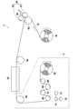
- FIG. 1 schematically shows an example of an apparatus configuration used in the production process of the acidic gas separation composite according to the present invention.
- the apparatus 100 is provided with a feed roll 10 for feeding a belt-like support 12 and a coater 20 for applying a coating solution 30 for forming an acidic gas separation layer on the support 12 (in FIG. 1, it rotates in the direction of the arrow in the figure).
- a drying unit including a drying furnace 40 for drying a membrane (not shown) and a winding process unit 5 including a winding roll 50 that winds up the obtained acidic gas separating composite 52 are provided. Further, transport rolls 62 (also functioning as backup rolls for the roll coater in FIG. 1) and 64 to 69 for transporting the support 12 to the respective parts 20, 40, 50 are arranged.
- a roll-to-roll that is, a support 12 is sent out from the feed roll 10 and the coating process is performed while the support 12 is conveyed, and The drying step is sequentially performed, and the obtained acidic gas separating composite 52 can be wound on the take-up roll 50, and the acidic gas separating composite 52 can be continuously and efficiently manufactured.
- a humidity detector 71 that detects the humidity of the winding A process unit 5 in order to perform humidity management of the winding process unit 5 from the discharge port of the drying furnace 40 to the winding roll 50. And when the humidity detected by the humidity detector 71 is 10% or more and 60% or less, dehumidification or humidification is performed in the process unit 5. And a control unit 73 for controlling the humidity adjusting device 72 so that the humidity of the liquid crystal is 10% to 60%, preferably 10% to 40%.
- only the winding process part 5 may be arrange
- one humidity detector 71 is provided in the winding process unit 5, but a plurality of humidity detectors 71 may be provided in the winding process unit 5. If the humidity in the winding process unit 5 is substantially uniform, one humidity detector 71 may be provided. However, if the humidity varies depending on the location in the winding process unit 5, for example, the outlet of the drying furnace 40 It is preferable to arrange the humidity detectors 71 at a plurality of locations, for example, in the vicinity of the vicinity of the take-up roll 50 or in the vicinity of the rollers of the conveyance path. Even if the humidity environment is not uniform in the winding process section 5, it is sufficient that the humidity is in the range of 10% to 60%.
- the winding process unit 5 surrounded by a dotted line in FIG. 1 may be disposed in a casing that can be humidity controlled separately from the coating and drying processes, and the humidity of the winding process unit 5 is 10% or more. As long as it can be controlled within a range of 60% or less, it may be exposed in an indoor facility.
- the humidity adjusting device 72 has a dehumidifying function and a humidifying function, but may be provided with only a dehumidifier or only a humidifier according to the natural environment of the area where the manufacturing is performed.
- the control unit 73 may be linked with a computer that controls the manufacturing apparatus 1 itself. When the humidity of the winding process unit 5 is 10% or more and 60% or less, the control unit 73 manufactures the complex 52 for acid gas separation. You may make it cancel.
- the acidic gas separation facilitated transport which is a gel film having a very high water absorption property. Problems caused by the film absorbing water in the ambient atmosphere can be suppressed, and sticking of the film to the transport roll in contact with the coating surface can be suppressed. Thereby, since contamination of the process path can be suppressed, efficient production is possible, and an acidic gas separation promoting transport membrane with few defects can be obtained.
- a mobile simple dehumidifier is installed in the vicinity of the winding roll 50, for example, and a form in which a high humidity is pressed (humidity adjustment) is adopted. May be.
- a simple hygrometer may be installed on the transport roll 68 or the take-up roll 50 and the overall air conditioning by the humidity adjusting device and the control unit may be adjusted by looking at the value.
- the humidity may be controlled to some extent by the air conditioning of the winding process unit or the entire manufacturing apparatus, and a hygrometer may be installed on the transport roll 68 and the winding roll 50 to make further adjustment of the air conditioning.
- a coating solution for forming an acidic gas separation facilitating transport film (hereinafter also referred to as “coating solution” for short) containing a hydrophilic compound, an acidic gas carrier, and water is prepared.
- coating solution a hydrophilic compound and an acidic gas carrier are respectively added to water in appropriate amounts.
- hydrophilic polymer is mentioned as a hydrophilic compound contained in a coating liquid.
- the hydrophilic polymer functions as a binder.
- the hydrophilic polymer retains moisture in the acidic gas separation promoting transport membrane and exerts a function of separating acidic gas by an acidic gas carrier.
- the hydrophilic polymer preferably has high water absorption from the viewpoint that the acidic gas separation facilitating transport membrane has high water absorption (retainability), and has a water absorption of 0.5 g / g or more in physiological saline.
- it has a water absorption of 1 g / g or more, more preferably 5 g / g or more, and particularly preferably 10 g / g or more. Further, it is most preferable to have a water absorption of 20 g / g or more.
- hydrophilic polymer contained in the coating solution a conventionally known hydrophilic polymer can be used.
- a conventionally known hydrophilic polymer can be used.
- these copolymers are also preferred, and these copolymers can also be preferably used.
- polyvinyl alcohol-polyacrylate copolymer particularly preferred is a polyvinyl alcohol-polyacrylate copolymer.
- the polyvinyl alcohol-polyacrylate copolymer has a high water absorption capacity and also has a high hydrogel strength even at high water absorption.
- the content of polyacrylate in the polyvinyl alcohol-polyacrylate copolymer is, for example, 1 to 95 mol%, preferably 2 to 70 mol%, more preferably 3 to 60 mol%, and particularly preferably 5 to 50 mol%. Mol%.
- polyacrylic acid salts include alkali metal salts such as sodium salt and potassium salt, as well as ammonium salts and organic ammonium salts.
- polyvinyl alcohol-polyacrylate copolymer sodium salt
- Crustomer AP20 trade name: manufactured by Kuraray Co., Ltd.
- Two or more hydrophilic polymers may be mixed and used.
- the content of the hydrophilic polymer in the coating liquid depends on the type, but from the viewpoint of forming a membrane as a binder and allowing the acidic gas separation promoting transport membrane to sufficiently retain moisture, 0.5% by mass
- the content is preferably 50% by mass or less, more preferably 1% by mass or more and 30% by mass or less, and particularly preferably 2% by mass or more and 15% by mass or less.
- the acid gas carrier means one that indirectly reacts with the acid gas or one that itself reacts directly with the acid gas.
- the acid gas carrier various water-soluble inorganic and organic substances showing basicity are used. Examples of the substance that reacts indirectly with the acid gas include those that react with other gases contained in the supply gas, show basicity, and react with the basic compound and the acid gas. More specifically react with steam OH - to the release, the OH - refers to alkali metal compounds can be incorporated selectively CO 2 in the film by reacting with CO 2 . Examples of those that react directly with acid gas include basic compounds such as nitrogen-containing compounds and sulfur oxides.
- alkali metal compound examples include at least one selected from alkali metal carbonates, alkali metal bicarbonates, or alkali metal hydroxides.
- alkali metal an alkali metal element selected from cesium, rubidium, potassium, lithium, and sodium is preferably used.
- an alkali metal compound is used in the meaning containing the salt and its ion other than alkali metal itself.
- Examples of the alkali metal carbonate include lithium carbonate, sodium carbonate, potassium carbonate, rubidium carbonate, and cesium carbonate.
- Examples of the alkali metal bicarbonate include lithium hydrogen carbonate, sodium hydrogen carbonate, potassium hydrogen carbonate, rubidium hydrogen carbonate, and cesium hydrogen carbonate.
- Examples of the alkali metal hydroxide include lithium hydroxide, sodium hydroxide, potassium hydroxide, cesium hydroxide, and rubidium hydroxide. Among these, alkali metal carbonates are preferable, and compounds containing cesium, rubidium, and potassium having high solubility in water are preferable. Moreover, you may mix and use 2 or more types of acidic gas carriers. For example, what mixed cesium carbonate and potassium carbonate can be mentioned suitably.
- nitrogen-containing compounds include amino acids such as glycine, alanine, serine, proline, histidine, taurine, and diaminopropionic acid, hetero compounds such as pyridine, histidine, piperazine, imidazole, and triazine, monoethanolamine, diethanolamine, and triazine.
- Alkanolamines such as ethanolamine, monopropanolamine, dipropanolamine, tripropanolamine, cyclic polyetheramines such as cryptand [2.1] and cryptand [2.2], cryptand [2.2.1] Bicyclic polyetheramines such as cryptand [2.2.2], porphyrin, phthalocyanine, ethylenediaminetetraacetic acid and the like can be used.
- amino acids such as cystine and cysteine, polythiophene, dodecylthiol and the like can be used.
- the content of the acidic gas carrier in the coating liquid is 0.3 to 30% by mass in order to prevent salting out before coating and to ensure the separation function of acidic gas, depending on the type. It is preferably 0.5 to 25% by mass, more preferably 1 to 20% by mass.
- the coating solution preferably contains a hydrophilic polymer and an acidic gas carrier in a mass ratio of 1: 9 to 2: 3. More preferably, it is in the range of 1: 4 or more and 2: 3 or less, more preferably 3: 7 or more and 2: 3 or less.
- Thickener Coating liquid composition for forming an acidic gas separation promoting transport film, comprising a hydrophilic polymer, an acidic gas carrier, and water, wherein the mass ratio of the hydrophilic polymer to the acidic gas carrier is from 1: 9 to 2: 3.
- a thickener may be further used in the coating solution composition.
- any compound may be used as long as it can increase the viscosity of the coating liquid composition within a temperature range of 15 ° C. or more and 35 ° C. or less.
- Carboxymethyl cellulose that can be suitably used has a degree of etherification in the range of 0.6 to 1.5, and a viscosity measurement value at a rotation speed of 60 rpm in a B-type viscosity measurement when the aqueous solution is 1% by mass is 1 Pa ⁇ It is in the range of s to 10 Pa ⁇ s.
- carboxymethylcellulose When such carboxymethylcellulose is used, a coating liquid composition for forming an acidic gas separation promoting transport film having a desired viscosity can be easily obtained with a small amount of content, and at least components other than the solvent contained in the coating liquid can be obtained. There is also little risk that a part of the coating solution cannot be dissolved and deposited.
- carboxymethylcellulose can be obtained from commercial products, and preferred examples include CMC2280 manufactured by Daicel Finechem Co., Ltd.
- the prepared coating solution for forming an acidic gas separation promoting transport film has a viscosity measurement value of 0.5 Pa ⁇ s or more at a rotation speed of 60 rpm in B-type viscosity measurement at any temperature within the range of 15 ° C. or more and 35 ° C. or less. Whether one of the viscosities in the range of 10 Pa ⁇ s or less is exhibited can be confirmed as follows. That is, the prepared coating solution for forming an acidic gas separation promoting transport film is put into a stainless steel container (for example, 4 cm in inner diameter and 12 cm in height) so that the viscometer cylinder (rotor) is sufficiently immersed in the coating solution. .
- the stainless steel container is immersed in a temperature-adjustable water tank, and while adjusting the temperature of the applied coating solution in the range of 15 ° C. to 35 ° C., a B-type viscometer (BL2 1-100,000 mPa, manufactured by Techjam) S / KN3312481) is operated, the value for each temperature at a rotational speed of 60 rpm is read, and the viscosity of the coating solution is measured according to JIS Z8803.
- a B-type viscometer BL2 1-100,000 mPa, manufactured by Techjam
- the content of the thickener in the composition (coating liquid) is 0.5 Pa ⁇ s at a rotation speed of 60 rpm in the B-type viscosity measurement at any temperature within the range of 15 ° C. to 35 ° C. If it can be adjusted to show any viscosity within the range of 10 Pa ⁇ s or less, it is preferably as small as possible. As a general index, it is preferably 10% by mass or less, more preferably 0.1% by mass or more and 5% by mass or less, and most preferably 0.1% by mass or more and 2% by mass or less.
- the hydrophilic polymer can be crosslinked by a conventionally known method such as thermal crosslinking, ultraviolet crosslinking, electron beam crosslinking, or radiation crosslinking. It is preferable that the composition of this invention contains a crosslinking agent. In particular, it preferably contains a cross-linking agent having two or more functional groups capable of reacting with the polyvinyl alcohol-polyacrylate copolymer and thermally cross-linking, and includes polyvalent glycidyl ether, polyhydric alcohol, polyvalent isocyanate, polyvalent aziridine, Examples include haloepoxy compounds, polyhydric aldehydes, polyhydric amines, and the like.
- polyvalent glycidyl ether for example, ethylene glycol diglycidyl ether, polyethylene glycol diglycidyl ether, glycerol polyglycidyl ether, diglycerol polyglycidyl ether, polyglycerol polyglycidyl ether, sorbitol polyglycidyl ether, pentaerythritol poly Examples thereof include glycidyl ether, propylene glycol glycidyl ether, and polypropylene glycol diglycidyl ether.
- polyhydric alcohol examples include ethylene glycol, diethylene glycol, triethylene glycol, tetraethylene glycol, polyethylene glycol glycerin, polyglycerin, propylene glycol, diethanolamine, triethanolamine, polyoxypropyl, and oxyethylene oxypropylene block. Copolymers, pentaerythritol, sobitol and the like can be mentioned.
- examples of the polyvalent isocyanate include 2,4-toluylene diisocyanate and hexamethylene diisocyanate.
- examples of the polyvalent aziridine include 2,2-bishydroxymethylbutanol-tris [3- (1-acylidinyl) propionate], 1,6-hexamethylenediethyleneurea, diphenylmethane-bis-4,4′- N, N′-diethylene urea and the like can be mentioned.
- Examples of the haloepoxy compound include epichlorohydrin and ⁇ -methylchlorohydrin.
- Examples of the polyvalent aldehyde include glutaraldehyde and glyoxal.
- Examples of the polyvalent amine include ethylenediamine, diethylenetriamine, triethylenetetramine, tetraethylenepentamine, pentaethylenehexamine, and polyethyleneimine.
- glutaraldehyde is particularly preferred as the thermal crosslinking agent for the polyvinyl alcohol-polyacrylate copolymer.
- the coating liquid can contain one or more other components (additives) other than the hydrophilic polymer, the acidic gas carrier, and the thickener as long as the coating properties and gas separation characteristics are not adversely affected.
- other components include, in addition to the above-described crosslinking agent, for example, surfactants, catalysts, moisturizing (water absorbing) agents, auxiliary solvents, film strength adjusting agents, and defect detecting agents.
- the coating liquid is prepared by adding the above-mentioned hydrophilic polymer, acidic gas carrier, and, if necessary, other additives including a thickener and a crosslinking agent to water (room temperature water or warm water) in appropriate amounts. It is performed with sufficient agitation, and if necessary, dissolution is accelerated by heating with agitation.
- a hydrophilic polymer and an acidic gas carrier may be separately added to water, or those previously mixed may be added.
- the hydrophilic polymer and the thickener are added by gradually adding a hydrophilic polymer and an acidic gas carrier thereto and stirring. Precipitation (salting out) can be effectively prevented.
- the coating liquid for forming an acidic gas separation promoting transport film is fed out from the feed roll 10 to the belt-like support 12 and conveyed to the coater 20 of the coating section.
- the measured viscosity value at a rotational speed of 60 rpm is applied on the support 12 at a viscosity of 0.5 Pa ⁇ s or more and 10 Pa ⁇ s or less, and a liquid film of the coating solution is provided on the support 12.
- the support 12 supports the acidic gas separation facilitated transport membrane, has an acid gas permeability, and is coated with an acidic gas separation facilitated transport membrane forming composition (coating liquid) so as to facilitate the acidic gas separation facilitated transport membrane.
- an acidic gas separation facilitated transport membrane forming composition coating liquid
- the film can be formed and the film can be supported.
- the material of the support 12 paper, fine paper, coated paper, cast coated paper, synthetic paper, and further, cellulose, polyester, polyolefin, polyamide, polyimide, polysulfone aramid, polycarbonate, metal, glass, ceramics and the like are preferable. Can be used.
- resin materials such as polypropylene, polyethylene, polystyrene, polyphenyl sulfide, polyether imide, polyether ether ketone, polysulfone, polyether sulfone, polyethylene terephthalate, polytetrafluoroethylene, and polyvinylidene fluoride are preferable.
- polyolefins and fluorides thereof can be particularly preferably used from the viewpoint of stability over time.
- a woven fabric, a non-woven fabric, a porous membrane or the like can be adopted. In general, a support having a high self-supporting property and a high porosity can be suitably used.
- Polysulfone, cellulose membrane filter membrane, polyamide, polyimide interfacial polymerized thin film, polytetrafluoroethylene, high molecular weight polyethylene stretched porous membrane has high porosity, low acid gas diffusion inhibition, strength, suitability for manufacturing, etc.
- a stretched film of polytetrafluoroethylene (PTFE) is particularly preferable.
- the support 12 it is particularly preferable to use a laminated film of a hydrophobic porous film and a nonwoven fabric as an auxiliary support film. Since the mechanical strength can be improved by providing an auxiliary support film, there is an effect that the support film does not wrinkle even when handled in a roll-to-roll coating apparatus, and productivity can also be improved. . In this case, it is particularly preferable to use PTFE as the hydrophobic porous film and polypropylene (PP) which is inexpensive and has high mechanical strength as the nonwoven fabric.
- PP polypropylene
- the hydrophobic porous membrane means that the surface of the porous membrane on the side in contact with the facilitated transport membrane is a hydrophobic surface. If the surface is hydrophilic, the facilitated transport film containing moisture in the use environment is likely to penetrate into the porous portion, and there is a concern that the film thickness distribution and performance deterioration with time may occur.
- the term “hydrophobic” means that the contact angle of water at room temperature (25 ° C.) is about 80 ° C. or more.
- the thickness of the support is preferably 30 to 500 ⁇ m, more preferably 50 to 300 ⁇ m, and even more preferably 50 to 200 ⁇ m.
- the Young's modulus of the support is preferably 0.4 GPa or more so that the support is not distorted or broken in the production of Roll-to-Roll.
- the porous film thickness is about 5 to 100 ⁇ m and the nonwoven film thickness is about 50 to 300 ⁇ m.
- the transport speed of the support 12 depends on the type of the support 12 and the viscosity of the composition (coating liquid), but if the transport speed of the support is too high, the film thickness uniformity of the coating film in the coating process is reduced. If it is too slow and productivity is too low, the productivity may decrease, and the viscosity of the composition may increase before the cooling step, which may reduce the uniformity of the coating film.
- the conveying speed of the support 12 may be determined according to the type of the support 12 and the viscosity of the composition in consideration of the above points, but is preferably 1 m / min or more. Furthermore, 10 m / min or more and 200 m / min or less is more preferable, and further 20 m / min or more and 200 m / min or less is particularly preferable.
- a roll coater or a blade coater is particularly preferable.
- the roll coater combines one or more rolls to control the amount of coating liquid held on the surface of the roll (applicator roll) arranged closest to the support, and the coating liquid on the (applicator roll) Is a coater that transfers a certain amount of the above to the support surface.
- Suitable roll coaters include a direct gravure coater, an offset gravure coater, a single roll kiss coater, a three reverse roll coater, and a forward rotation roll coater.
- a three reverse roll coater suitable for application of a coating solution having a medium viscosity to a high viscosity of 3 Pa ⁇ s or more and 20 Pa ⁇ s or less is preferable.
- the blade coater is a coater that, after applying an excessive amount of coating solution on a support, scrapes off the excess amount of the coating solution on the support with a blade.
- the drying step at least a part of water as a solvent contained in the coating film of the acidic gas separation layer forming coating solution formed on the support in the coating step is removed in the drying furnace 40.
- a drying step is performed by heating the support on which the coating film is held, blowing dry air on the coating film, or both.
- the temperature is more preferably 60 ° C. or higher and 90 ° C. or lower, and further preferably 70 ° C. or higher and 80 ° C. or lower.
- the film surface temperature is preferably 15 ° C. or higher and 80 ° C. or lower, more preferably 30 ° C. or higher and 70 ° C. or lower.
- the crosslinking step may be performed simultaneously with the drying step or may be performed separately.
- a well-known crosslinking method can be used for the crosslinking method.
- the acidic gas separation promoting transport membrane may be heated and crosslinked by heating means such as an infrared heater after the drying step, or may be crosslinked together with drying by warm air in the drying step.
- Thermal crosslinking can be performed by heating to about 100 to 150 ° C., for example.
- UV or electron beam crosslinking may be applied to the liquid film of the coating solution formed on the support and then dried.
- the acidic gas separation composite 52 in which the liquid film of the coating liquid for forming the acidic gas separation facilitated transport film applied in the coating step on the support is dried in a drying furnace to form the acidic gas separation facilitated transport film. Is wound up by a winding roll. At this time, the humidity of the winding process unit 5 is measured by the humidity detector 71, and the control unit 73 controls the humidity adjusting device 72 to adjust the humidity of the winding process unit 5 according to the measured humidity. Is performed in an environment of 10% to 60%.
- the composite for acidic gas separation according to the present invention is obtained through the above steps.
- FIG. 2 is a schematic block diagram showing a spiral-shaped acidic gas separation module 100 according to the first embodiment of the acidic gas separation module of the present invention, which is partially cut away.
- the acidic gas separation module 100 has a basic structure in which the outermost periphery of the laminate 114 is wound around a permeate gas collecting pipe 112 in a state where one or more laminates 114 described below are wound. Covered with a covering layer 116, telescope prevention plates 118 are attached to both ends of these units.
- the module 100 having such a configuration, when the source gas 120 containing an acidic gas is supplied to the laminate 114 from the one end 100A side, the source gas 120 is mixed with the acid gas 122 and the remaining gas by the configuration of the laminate 114. It is separated into 124 and discharged separately to the other end 100B side.
- the permeate gas collecting pipe 112 is a cylindrical pipe having a plurality of through holes 112A formed in the pipe wall.
- the one end side (one end 100A side) of the permeate gas collecting pipe 112 is closed, and the other end side (the other end 100B side) of the permeate gas collecting pipe 112 is opened and penetrates the laminate to collect from the through hole 112A.
- a discharge port 126 from which acidic gas 122 such as gas is discharged is provided.
- the shape of the through hole 112A is not particularly limited, but it is preferable that a circular hole with a diameter of 1 to 20 mm ⁇ is opened. Further, it is preferable that the through holes 112A are arranged uniformly with respect to the surface of the permeate gas collecting pipe 112.
- the covering layer 116 is formed of a blocking material capable of blocking the raw material gas 120 passing through the acidic gas separation module 100.
- This blocking material preferably further has heat and humidity resistance.
- heat resistance in the heat and humidity resistance means having a heat resistance of 80 ° C. or higher.
- the heat resistance of 80 ° C. or higher means that the shape before storage is maintained even after being stored for 2 hours under a temperature condition of 80 ° C. or higher, and curling that can be visually confirmed by heat shrinkage or heat melting does not occur.
- “moisture resistance” of the heat and humidity resistance is a curl that can be visually confirmed by heat shrinkage or heat melting even after being stored at 40 ° C. and 80% RH for 2 hours. It means not occurring.
- the telescope prevention plate 118 is preferably made of a heat and moisture resistant material.
- the laminated body 114 is formed by laminating a permeating gas flow path member 16, an acidic gas separation complex 110, a supply gas flow path member 130, and an acidic gas separation complex 110. It is wound around the permeating gas collecting pipe 112. By laminating these films, the source gas 120 containing the acid gas 122 is supplied from the end of the supply gas flow path member 130 and is separated through the acid gas separation complex 110 partitioned by the coating layer 116.
- the acidic gas 122 collected in the permeated gas collecting pipe 112 is collected through the permeated gas flow path member 16 and the through hole 112A, and is collected from the discharge port 126 connected to the permeated gas collecting pipe 112. Further, the residual gas 124 from which the acidic gas 122 has been separated that has passed through the gap or the like of the supply gas flow path member 130 is discharged from the end of the acidic gas separating mogas separation complex 110.
- the complex for acidic gas separation 110 is produced by the production method of the present invention, and is a porous support formed by laminating a porous membrane and an auxiliary support membrane, on the porous membrane side of the porous support. It is composed of an acidic gas separation promoting transport film including an acidic gas carrier that reacts with at least the hydrophilic polymer and the acidic gas in the raw material gas.
- the number of the laminated body 114 wound around the permeate gas collecting pipe 112 is not particularly limited, and may be single or plural. By increasing the number (number of laminated layers), the membrane area of the facilitated transport film can be improved. Thereby, the quantity which can isolate
- the supply gas flow path member 130 is a member to which a source gas containing an acid gas is supplied from one end of the acid gas separation module, has a function as a spacer, and causes a turbulent flow in the source gas. Therefore, a net-like member is preferably used. Since the gas flow path changes depending on the shape of the net, the shape of the unit cell of the net is selected from shapes such as rhombus and parallelogram according to the purpose. Assuming that a raw material gas containing water vapor is supplied at a high temperature, the supply gas flow path member preferably has moisture and heat resistance in the same manner as the acidic gas separation layer described later.
- the material of the supply gas flow path member 130 is not limited in any way, but paper, fine paper, coated paper, cast coated paper, synthetic paper, cellulose, polyester, polyolefin, polyamide, polyimide, polysulfone, aramid, Examples thereof include resin materials such as polycarbonate and inorganic materials such as metal, glass and ceramics.
- the resin materials include polyethylene, polystyrene, polyethylene terephthalate, polytetrafluoroethylene (PTFE), polyethersulfone (PES), polyphenylene sulfide (PPS), polysulfone (PSF), polypropylene (PP), polyimide, polyetherimide, poly Suitable examples include ether ether ketone and polyvinylidene fluoride.
- preferable materials from the viewpoint of heat and humidity resistance include inorganic materials such as ceramics, glass, and metals, organic resin materials having heat resistance of 100 ° C. or higher, high molecular weight polyester, polyolefin, heat resistant polyamide, polyimide, and the like.
- Polysulfone, aramid, polycarbonate, metal, glass, ceramics and the like can be suitably used. More specifically, at least one selected from the group consisting of ceramics, polytetrafluoroethylene, polyvinylidene fluoride, polyethersulfone, polyphenylene sulfide, polysulfone, polyimide, polypropylene, polyetherimide, and polyetheretherketone. It is preferable that it is comprised including these materials.
- the thickness of the supply gas flow path member is not particularly limited, but is preferably 100 ⁇ m or more and 1000 ⁇ m or less, more preferably 150 ⁇ m or more and 950 ⁇ m or less, and further preferably 200 ⁇ m or more and 900 ⁇ m or less.
- the permeating gas channel member 16 is a member in which the acidic gas that has reacted with the carrier and permeated the acidic gas separating complex 110 flows toward the through hole.
- the permeate gas flow path member 16 has a function as a spacer, and also has a function of causing the permeated acidic gas to flow inside the permeate gas flow path member 16.
- An example is a tricot knitting shape.
- the material of the permeating gas flow path member can be the same as that of the supply gas flow path member.
- the permeate gas channel member has moisture and heat resistance in the same manner as the acidic gas separation layer.
- polyesters such as epoxy-impregnated polyester, polyolefins such as polypropylene, and fluorines such as polytetrafluoroethylene.
- the thickness of the permeating gas channel member is not particularly limited, but is preferably 100 ⁇ m or more and 1000 ⁇ m or less, more preferably 150 ⁇ m or more and 950 ⁇ m or less, and further preferably 200 ⁇ m or more and 900 ⁇ m or less.
- the complex for acid gas separation produced by the production method of the present invention may be installed as a flat membrane, a spiral type known as a reverse osmosis membrane module, for example, JP 2010-279885 A, etc. It can also be used after being processed into a pleated mold having a shape as described in 1. Furthermore, the carbon dioxide separation module according to the present invention can be used by being set in a carbon dioxide separator.
- Example 1 (Preparation process) 5% cesium carbonate aqueous solution, 2.5% PVA-PAA copolymer (Kuraray; Clastomer AP) and 0.3% glutaraldehyde (manufactured by Wako Pure Chemical Industries, Ltd.) are heated and stirred to separate acidic gases. As the coating solution, a coating solution for carbon dioxide separation was prepared.
- the blade coating method was selected, and the coating was performed with a liquid film thickness of 0.3 mm by adjusting the blade height to 0.3 mm.
- drying process In the coating step, the liquid film was dried in a drying furnace. Drying was a method of volatilizing water from the liquid membrane by passing continuously through a 3.0 m drying zone by a hot air method, and a carbon dioxide separation membrane was formed on the support.
- the drying zone 1-2 was 60 ° C.
- the drying zone 3-4 was 80 ° C.
- the drying zone 5-7 was 90 ° C.
- thermo-hygrometer ONDOTORI JC-M3200, manufactured by Nippon Keiki Kogyo Co., Ltd.
- the temperature and humidity were controlled.
- the wind-up part from the drying outlet can be adjusted in the common low humidity package 5.
- Air with adjusted temperature and humidity at a setting of 25 ° C. and 35% was supplied from the drying outlet to the winding unit. Specifically, the air whose humidity has been adjusted by the package is supplied between the roll 65 and the roll 66 in FIG. At this time, the humidity detected by the hygrometer was 40% at the drying outlet and 38% at the winding part.
- Example 2 Coating was performed with a liquid film thickness of 1.5 mm by adjusting the blade height in Example 1 to 1.5 mm.
- the drying zone 1-2 was 70 ° C.
- the drying zone 3-4 was 90 ° C.
- the drying zone 5-7 was 100 ° C.
- the temperature and humidity conditions at the take-up portion from the drying outlet were the same as in Example 1.
- Example 3 By adjusting the blade height in Example 1 to 3.0 mm, coating was performed with a liquid film thickness of 3.0 mm.
- the drying zone 1-2 was 80 ° C.
- the drying zone 3-4 was 100 ° C.
- the drying zone 5-7 was 110 ° C.
- the temperature and humidity conditions at the take-up portion from the drying outlet were the same as in Example 1.
- Example 4 By adjusting the blade height in Example 1 to 3.0 mm, coating was performed with a liquid film thickness of 3.0 mm.
- the drying zone 1-2 was 80 ° C.
- the drying zone 3-4 was 100 ° C.
- the drying zone 5-7 was 110 ° C.
- the set value of the package in the winding part was set to 25 ° C. and 50%, and air adjusted in temperature and humidity was supplied from the drying outlet to the winding part.
- Example 5 In Example 1, air whose temperature and humidity were adjusted from the drying outlet to the winding portion was set to 25 ° C. and 10% from the drying outlet to the winding portion.
- Example 6 In Example 4, air whose temperature and humidity were adjusted at a set value of the package at the winding portion from the drying outlet of 25 ° C. and 59% was supplied from the drying outlet to the winding portion.
- Example 1 By adjusting the blade height to 0.1 mm in Example 1, coating was performed with a liquid film thickness of 0.1 mm.
- the drying zone 1-2 was 60 ° C.
- the drying zone 3-4 was 80 ° C.
- the drying zone 5-7 was 90 ° C. From the drying outlet, air whose temperature and humidity were adjusted at a set value of the package in the winding part at 25 ° C. and 35% was supplied from the drying outlet to the winding part.
- Example 2 Coating was performed with a liquid film thickness of 4.0 mm by adjusting the blade height in Example 1 to 4.0 mm.
- the drying zone 1-2 was 80 ° C.
- the drying zone 3-4 was 100 ° C.
- the drying zone 5-7 was 110 ° C. From the drying outlet, air whose temperature and humidity were adjusted at a set value of the package in the winding part at 25 ° C. and 35% was supplied from the drying outlet to the winding part.
- Comparative Example 3 In Comparative Example 2, the drying zone 1-2 was 90 ° C., the drying zone 3-4 was 110 ° C., and the drying zone 5-7 was 130 ° C.
- the permeated gas was analyzed with a gas chromatograph, and the CO 2 permeation rate (P (CO 2 )) was calculated. Production and performance evaluation of a carbon dioxide separation membrane were carried out 5 times, and evaluated according to the following criteria.
- C Average value is less than 20 GPU
Abstract
【課題】高い生産性で分離特性に優れた酸性ガス分離用複合体を製造する。 【解決手段】多孔質支持体(12)上に原料ガス中の酸性ガスを分離する機能を有する酸性ガス分離促進輸送膜を備えてなる酸性ガス分離用複合体(52)をロール・トゥ・ロール方式で製造する製造方法であって、親水性化合物、酸性ガスキャリアおよび水を含む、酸性ガス促進輸送膜の形成用塗布液を調製する調製工程と、形成用塗布液を液膜厚さ0.3mmから3.0mmで支持体上に塗布する塗布工程と、塗布された液膜を、乾燥炉(40)にて乾燥させて酸性ガス促進輸送膜を形成し、支持体(12)上に酸性ガス促進輸送膜が形成されてなる酸性ガス分離用複合体(52)を巻取りロール(50)に巻き取る巻取工程とを含み、巻取工程を行う巻取り工程部(5)の湿度を計測し、湿度が10%以上60%以下となるように管理し、管理された湿度条件下で巻取工程を行う。
Description
本発明は、酸性ガス分離機能を有する酸性ガス分離用複合体の製造方法および製造装置に関するものである。
近年、混合ガス中の酸性ガスを選択的に分離する技術の開発が進んでいる。特には、二酸化炭素を選択的に分離する技術の開発が進んでいる。例えば、地球温暖化対策として排ガス中の二酸化炭素を回収して濃縮する技術や、水蒸気改質により炭化水素を水素と一酸化炭素(CO)に改質し、さらに一酸化炭素と水蒸気を反応させて二酸化炭素と水素を生成させ、二酸化炭素を選択的に透過する膜によって二酸化炭素を排除することで水素を主成分とする燃料電池用等のガスを得る技術が開発されている。
一方、二酸化炭素の分離はアミン類による吸着及び放散を繰り返すアミン吸収法が一般的で広く用いられてきている。しかしながらこの方法は広大な設備設置面積を必要とする上に吸着/放散時に昇圧/降圧、及び降温/昇温を繰り返す必要があり、多大なエネルギーを必要とする欠点を有している。またシステムの能力は設計時に決定してしまい、一旦作られたシステムの能力の拡縮は容易でない。これに対して、膜分離法は分離膜で区画された2つの領域の二酸化炭素分圧により自然に分離を行うものでエネルギー消費が少なく、かつ設置面積がコンパクトな利点を有する。またシステムの能力の拡縮もフィルターユニットの増減で対応出来るためにスケーラビリティーに優れたシステムが可能であり、近年注目を浴びている。
膜分離法に用いられる二酸化炭素分離用複合体は、支持体上の二酸化炭素分離層中に、二酸化炭素キャリアを含有し、このキャリアによって二酸化炭素が膜の反対側に輸送される、いわゆる促進輸送膜と、二酸化炭素分離層に対する二酸化炭素と二酸化炭素以外の分離対象ガス(以下、単に「分離対象物質」という。)との間での溶解性、及び膜中の拡散性の差を利用して分離を行う、いわゆる溶解拡散膜とに大別される。
溶解拡散膜は、二酸化炭素と分離対象物質との間での当該膜への溶解性及び当該膜中の拡散性の差に基づいて分離を行うため、膜の材質及び物性が決まればその分離度合いは一義的に決定され、かつ、膜厚が薄いほど混合ガスの透過速度が大きくなる。そのため、溶解拡散膜は、一般的に層分離法、界面重合法などの製造方法を用いて、膜厚が1μm以下の薄膜として製造される。
これに対して、促進輸送膜は膜中の二酸化炭素キャリアにより二酸化炭素の溶解度を飛躍的に増大させ、膜中での二酸化炭素の輸送が高濃度で行われるため、一般的に溶解拡散膜に比べ分離対象物質に対する二酸化炭素の分離度合いが高く、また二酸化炭素の透過速度が速いという特長を有する。また膜中の二酸化炭素濃度が高濃度であることから、膜中の二酸化炭素の拡散速度が律速になることは希であり、むしろ分離対象物質との分離度合いを上げる意味からは10μm以上の厚膜とする方が好ましい。
例えば、特許文献1には、未架橋のビニルアルコール-アクリル酸塩共重合体水溶液を二酸化炭素透過性支持体上へ膜状に塗布して、当該支持体上に未架橋のビニルアルコール-アクリル酸塩共重合体水溶液の液膜を形成した後、この液膜を加熱して架橋させることにより水不溶化膜とし、この水不溶化膜に、二酸化炭素キャリア(二酸化炭素と親和性を有する物質)を含む水溶液を吸収させてハイドロゲル膜とした二酸化炭素分離用複合体の製造方法が記載されている。
特許文献2には、ポリビニルアルコール-ポリアクリル酸共重合体およびアルカリ金属炭酸塩を含む塗布液に寒天などのゲル化剤を添加し、50℃以上で調製した塗布液を支持体上に塗布した後、液膜を冷却させて硬化させる二酸化炭素分離用複合体の製造方法が記載されている。
特許文献1に記載されている二酸化炭素分離用複合体の製造方法においては、二酸化炭素透過性支持体上に、二酸化炭素キャリアを含まないビニルアルコール-アクリル酸塩共重合体水溶液を塗布する工程、加熱して架橋して水不溶化膜を形成する工程、及び当該水不溶化膜に二酸化炭素キャリアを含む水溶液を吸収させる工程の少なくとも三つの工程が必要である。そのため、生産効率が悪く、生産コストが高価となり、しかも各工程のばらつきが重ね合わさって、二酸化炭素分離用複合体としての性能の変動が大きくならざるを得ないという課題がある。
また、特許文献2に記載されているCO2促進輸送膜を有する二酸化炭素分離用複合体の製造方法においては、ポリビニルアルコール-ポリアクリル酸共重合体などの親水性化合物とアルカリ金属炭酸塩などのキャリアを含む水溶液にゲル化剤を添加しているので、ゲル化剤の導入工程や塗膜の冷却工程が必要となる。そのため、製造工程が長くなりがちであり、工程の簡略化、効率化が課題となっている。
さらに、促進輸送膜は親水性ポリマーなどの親水性化合物とアルカリ金属炭酸塩などの二酸化炭素キャリアとが構成材料であり、これらはいずれも吸水量が非常に大きな材料であるため、上記組成物を支持体上に塗工後乾燥して乾膜を得たとしても、湿度の高い環境下では製造上種々の問題が生じる。例えば、上記二酸化炭素分離膜をロール・トゥ・ロールで製造する場合、乾燥炉出口から巻き取り工程の間で吸水したゲル膜がゲル膜に接触するパスロール表面に貼り付き、膜剥がれや工程汚染(ゲル膜付着、アルカリ水溶液でロールが濡れる、塗れることによる拭き作業、グリップ効果による膜変形)を引き起こす。また巻き取り部では、吸水したゲル膜が塗工面とは反対面の支持体(支持体裏面)と接触することで、ゲル膜と支持体裏面との貼り付きが生じ、剥がす際に膜面に傷が生じたり、膜面に凹凸が発生したりすることにより、促進輸送膜として所望の性能を得ることができないことが、本発明者らの研究により明らかになってきた。
以上の問題点は、二酸化炭素分離機能を有する二酸化炭素分離用複合体の製造に限らず、他の酸性ガスの分離機能を有する酸性ガス分離用複合体の製造においても共通する問題点である。
本発明は、上記課題に鑑みてなされたものであり、膜欠陥が抑制された所定の酸性ガスの分離度合いが高い酸性ガス分離促進層を有する酸性ガス分離用複合体が少ない工程数で、効率よく製造される酸性ガス分離用複合体の製造方法およびその製造装置を提供することを目的とする。
本発明の酸性ガス分離用複合体の製造方法は、多孔質支持体上に原料ガス中の酸性ガスを分離する機能を有する酸性ガス分離促進輸送膜を備えてなる酸性ガス分離用複合体をロール・トゥ・ロール方式で製造する製造方法であって、
親水性化合物、酸性ガスキャリアおよび水を含む、酸性ガス促進輸送膜の形成用塗布液を調整する塗布液調整工程と、
形成用塗布液を液膜厚さ0.3mmから3.0mmで支持体上に塗布する塗布工程と、
先に塗布された液膜を、乾燥炉にて乾燥させて酸性ガス促進輸送膜を形成する乾燥工程と、
支持体上に酸性ガス促進輸送膜が形成されてなる酸性ガス分離用複合体を巻取りロールに巻き取る巻取工程とを含み、
巻取工程を行う巻取り工程部の湿度を計測し、湿度が10%以上60%以下となるように管理し、管理された湿度条件下で巻取工程を行う。
親水性化合物、酸性ガスキャリアおよび水を含む、酸性ガス促進輸送膜の形成用塗布液を調整する塗布液調整工程と、
形成用塗布液を液膜厚さ0.3mmから3.0mmで支持体上に塗布する塗布工程と、
先に塗布された液膜を、乾燥炉にて乾燥させて酸性ガス促進輸送膜を形成する乾燥工程と、
支持体上に酸性ガス促進輸送膜が形成されてなる酸性ガス分離用複合体を巻取りロールに巻き取る巻取工程とを含み、
巻取工程を行う巻取り工程部の湿度を計測し、湿度が10%以上60%以下となるように管理し、管理された湿度条件下で巻取工程を行う。
巻取り工程において、湿度が10%以上40%以下となるように管理することがより好ましい。本明細書において、湿度とは相対湿度である。
支持体として、疎水性多孔質膜と不織布との積層膜を用い、その積層膜の疎水性多孔質膜上に塗布液を塗布することが好ましい。
親水性化合物は親水性ポリマーであることが好ましい。また、親水性ポリマーとしては、ポリビニルアルコール-ポリアクリル酸共重合体が好ましい。
酸性ガスキャリアが、アルカリ金属炭酸塩から選ばれる少なくとも1つを含む化合物を含有することが好ましい。
乾燥炉において、乾燥炉入口側から排出側に向かうにつれて、温度が60℃以上120℃以下の範囲で、徐々に高くなるように調整して液膜を乾燥させることが好ましい。
本発明の酸性ガス分離用複合体を製造する製造装置は、多孔質支持体上に原料ガス中の酸性ガスを分離する機能を有する酸性ガス分離促進輸送膜を備えてなる酸性ガス分離用複合体をロール・トゥ・ロール方式で製造する製造装置であって、
親水性化合物、酸性ガスキャリアおよび水を含む、酸性ガス促進輸送膜の形成用塗布液を液膜厚さ0.3mmから3.0mmで支持体上に塗布する塗布部と、
乾燥炉にて塗布された液膜を乾燥させて酸性ガス促進輸送膜を形成する乾燥部と、
支持体上に酸性ガス促進輸送膜が形成されてなる酸性ガス分離用複合体を巻取りロールに巻き取る巻取工程部とを備え、
巻取工程部に、巻取工程部の湿度を計測する湿度検出器と、湿度が10%以上60%以下となるように調整する湿度調整手段と、湿度検出器により計測された湿度に応じて湿度調整手段による調整を制御する制御手段とを備えている。
親水性化合物、酸性ガスキャリアおよび水を含む、酸性ガス促進輸送膜の形成用塗布液を液膜厚さ0.3mmから3.0mmで支持体上に塗布する塗布部と、
乾燥炉にて塗布された液膜を乾燥させて酸性ガス促進輸送膜を形成する乾燥部と、
支持体上に酸性ガス促進輸送膜が形成されてなる酸性ガス分離用複合体を巻取りロールに巻き取る巻取工程部とを備え、
巻取工程部に、巻取工程部の湿度を計測する湿度検出器と、湿度が10%以上60%以下となるように調整する湿度調整手段と、湿度検出器により計測された湿度に応じて湿度調整手段による調整を制御する制御手段とを備えている。
本発明の酸性ガス分離用複合体の製造方法によれば、ロール・トゥ・ロール方式による製造において、巻取りロールにより酸性ガス分離用複合体を巻き取る巻取り工程部の湿度が管理され管理された湿度環境下で巻取工程を行うので、吸水性が大きい酸性ガス分離促進輸送膜が吸水しすぎないように制御でき、酸性ガス分離促進輸送膜がパスロール表面に貼り付き、膜剥がれや工程汚染(ゲル膜付着、アルカリ水溶液でロールが濡れる、塗れることによる拭き作業、グリップ効果による膜変形)を引き起こすことを抑制することができ、また巻き取りロールに巻き取られる際に、酸性ガス分離促進輸送膜が支持体裏面と貼り付くのを抑制することができる。工程汚染が抑制されるため、効率よく製造を行うことができ、促進輸送面の膜面の欠陥の発生を抑制することができるので、分離性能の高い酸性ガス分離用複合体を製造することができる。
また、本発明の製造方法では、寒天のようなゲル化剤を要しないため、特許文献2において必要とされたゲル化剤の添加や塗布液塗布後の冷却工程は不要であり、工程が簡略され、さらに効率的な製造が可能である。
以下、図面を参照して本発明の実施形態を説明する。
<酸性ガス分離用複合体の製造方法>
本発明の酸性ガス分離用複合体の製造方法は、多孔質支持体上に原料ガス中の酸性ガスを分離する機能を有する酸性ガス分離促進輸送膜を備えてなる酸性ガス分離用複合体をロール・トゥ・ロール方式で製造する製造方法であって、親水性化合物、酸性ガスキャリアおよび水を含む、酸性ガス促進輸送膜の形成用塗布液を調整する塗布液調整工程と、その形成用塗布液を液膜厚さ0.3mmから3.0mmで多孔質支持体上に塗布する塗布工程と、塗布された液膜を、乾燥炉にて乾燥させて酸性ガス促進輸送膜を形成する乾燥工程と、支持体上に酸性ガス促進輸送膜が形成されてなる酸性ガス分離用複合体を巻取りロールに巻き取る巻取工程とを含み、巻取工程を行う巻取り工程部の湿度を計測し、湿度が10%以上60%以下となるように管理し、管理された湿度条件下で巻取工程を行うこととしている。
本発明の酸性ガス分離用複合体の製造方法は、多孔質支持体上に原料ガス中の酸性ガスを分離する機能を有する酸性ガス分離促進輸送膜を備えてなる酸性ガス分離用複合体をロール・トゥ・ロール方式で製造する製造方法であって、親水性化合物、酸性ガスキャリアおよび水を含む、酸性ガス促進輸送膜の形成用塗布液を調整する塗布液調整工程と、その形成用塗布液を液膜厚さ0.3mmから3.0mmで多孔質支持体上に塗布する塗布工程と、塗布された液膜を、乾燥炉にて乾燥させて酸性ガス促進輸送膜を形成する乾燥工程と、支持体上に酸性ガス促進輸送膜が形成されてなる酸性ガス分離用複合体を巻取りロールに巻き取る巻取工程とを含み、巻取工程を行う巻取り工程部の湿度を計測し、湿度が10%以上60%以下となるように管理し、管理された湿度条件下で巻取工程を行うこととしている。
本発明に係る塗布液調製工程においては、親水性ポリマーなどの親水性化合物、酸性ガスキャリア及び水を含む酸性ガス分離層形成用塗布液を調製する。
塗布液の粘度としては、塗布後の表面性やと高速度の観点から、0.5~5Pa・s(500~5000cp)が好ましく1~2Pa・s(1000~2000cp)がより好ましい。このときの粘度とは、B型粘度計において60rpmかつ液温度25℃における値とする。粘度0.5Pa・s以上であれば、塗布後の膜の流動を抑え膜厚を均一なものとすることができる。また、粘度が5Pa・sを超えると塗布液の気泡除去が困難となり、膜厚の均一化が難しくなる。
塗布液の粘度としては、塗布後の表面性やと高速度の観点から、0.5~5Pa・s(500~5000cp)が好ましく1~2Pa・s(1000~2000cp)がより好ましい。このときの粘度とは、B型粘度計において60rpmかつ液温度25℃における値とする。粘度0.5Pa・s以上であれば、塗布後の膜の流動を抑え膜厚を均一なものとすることができる。また、粘度が5Pa・sを超えると塗布液の気泡除去が困難となり、膜厚の均一化が難しくなる。
塗布工程においては、調製された酸性ガス促進輸送膜の形成用塗布液を液膜厚さ0.3mmから3.0mmで多孔質支持体上に塗布する。液膜が0.3mm以上であれば、形成される酸性ガス促進輸送膜において十分な酸性ガス分離機能を得ることができる。また、液膜が3.0mm以下であれば塗工時の気泡や異物による欠陥の発生を抑制することできる。液膜の厚さは、1.0mm以上2.5mm以下の範囲が更に好ましく、1.0mm以上2.0mm以下の範囲が特に好ましい。
支持体としては、特には、疎水性の多孔質膜が補助支持膜としての不織布との積層膜を用いることが好ましい。補助支持膜を備えることにより力学的強度を向上させることができるので、ロール・トゥ・ロールの塗布装置においてハンドリングしても支持膜にしわがよらないなどの効果があり、生産性を高めることもできる。
支持体としては、特には、疎水性の多孔質膜が補助支持膜としての不織布との積層膜を用いることが好ましい。補助支持膜を備えることにより力学的強度を向上させることができるので、ロール・トゥ・ロールの塗布装置においてハンドリングしても支持膜にしわがよらないなどの効果があり、生産性を高めることもできる。
塗布方法としては、上述の粘度の塗布液を上記の厚みで塗布できるも方法であれば特に限定されない。粘度が高く、厚みがあついため、直前に大量の塗布液を支持体上に転写した後、後の機工で所望の厚みに調整する、ロールコート法やブレードコート法などの後計量方式が最も適している。その他の塗布方法としては、エクストルージョン塗布法、ディップコート法、バーコート法、カーテンコート法等を採用してもよい。また複数の塗布方法を組み合わせてもよい。ロールコート法およびブレードコート法が生産設備上安価である点からも好ましい。
乾燥工程においては、塗布された液膜を、乾燥炉にて乾燥させて酸性ガス促進輸送膜を形成する。ここで、「乾燥」とは、塗布工程で支持体上に形成された酸性ガス分離促進輸送膜形成用塗布液の液膜に含まれる水の少なくとも一部を除去することを意味する。
乾燥炉の温度は60~120℃の範囲で適宜定めることが好ましい。60℃以上であれば、乾燥時間を実用的な時間に抑えることができる。他方、高温側は主として支持体の耐熱性に応じて適宜定めることができ、ここでは120℃程度としている。
乾燥炉の温度は60~120℃の範囲で適宜定めることが好ましい。60℃以上であれば、乾燥時間を実用的な時間に抑えることができる。他方、高温側は主として支持体の耐熱性に応じて適宜定めることができ、ここでは120℃程度としている。
なお、膜面の安定性から乾燥炉の温度は60~90℃が好ましく、70~80℃がより好ましい。乾燥方法は、温風による乾燥方法や赤外線ヒータによる乾燥方法など種々の乾燥方法を適用することができる。なお、乾燥炉内は60~120℃であれば、均一な温度でなくても構わない。また、乾燥炉入口側から乾燥炉出口(排出口)側に向かって徐々に温度が高くなるように設定することがより好ましい。例えば、乾燥炉入口近傍を70℃、乾燥炉中央付近を80℃、乾燥炉出口付近を90℃に設定するなどである。
巻取工程は、支持体上に酸性ガス分離促進輸送膜が形成されてなる酸性ガス分離用複合体を巻取りロールに巻き取る工程である。本発明においては、巻取工程が行われる、乾燥炉出口後から巻取ロールまでを含む巻取り工程部の湿度を管理し、湿度が10%以上60%以下の環境下で巻取り工程を行う。より好ましくは巻取り工程における環境湿度が10%以上40以下となるように管理する。
湿度が10%以上であれば、乾燥後に生成される酸性ガス分離促進輸送膜の膜割れ発生を抑制することができる。また、湿度が60%以下であれば、酸性ガス分離促進輸送膜中の含水率を20%以下に抑制することができるので、塗布面が搬送ロール表面に貼り付く等の問題を抑制することができ、膜欠陥の発生を抑えることができる。ここで含水率は露点-20℃環境下での10cm角の促進輸送膜の質量をA、25℃、相対湿度20%環境における10cm角の促進輸送膜の質量をBとしたときに、以下の計算式により算出される値である。
(B-A)÷B×100
湿度が10%以上であれば、乾燥後に生成される酸性ガス分離促進輸送膜の膜割れ発生を抑制することができる。また、湿度が60%以下であれば、酸性ガス分離促進輸送膜中の含水率を20%以下に抑制することができるので、塗布面が搬送ロール表面に貼り付く等の問題を抑制することができ、膜欠陥の発生を抑えることができる。ここで含水率は露点-20℃環境下での10cm角の促進輸送膜の質量をA、25℃、相対湿度20%環境における10cm角の促進輸送膜の質量をBとしたときに、以下の計算式により算出される値である。
(B-A)÷B×100
乾燥炉出口から巻取りロールまでの巻取り工程部の湿度は均一でなくてもよいが、塗布膜が通過、存在する箇所の湿度はいずれも10%以上60%以下の環境下において巻取り工程を行う必要がある。
なお、環境温度は15~35℃、好ましくは20~30℃である。
なお、環境温度は15~35℃、好ましくは20~30℃である。
なお、酸性ガス分離促進輸送膜の形成用塗布液においては、吸水性ポリマーと酸性ガスキャリアとの質量比が1:9以上2:3以下とすることが好ましい。
酸性ガス分離層形成用塗布液おいて、親水性ポリマーと酸性ガスキャリアとの質量比が1:9以上2:3以下であることは、当該塗布液を15℃以上35℃以下の温度条件下において、B型粘度測定において回転数60rpmにおける粘度測定値0.5Pa・s以上10Pa・s以下の粘度で支持体上に塗布して、酸性ガス形成用塗布液の液膜を支持体上に形成する塗布工程を可能とする。親水性ポリマーと酸性ガスキャリアとの質量比が1:9より小さくなると、15℃以上35℃以下の温度範囲で、B型粘度測定において回転数60rpmにおける粘度測定値が0.5Pa・s以上の粘度を示す塗布液を得ることが困難である。他方、親水性ポリマーと酸性ガスキャリアとの質量比が2:3より大きくなると、塗布液(水溶液)に含まれる固形分が均一に混合せずに白濁し、場合によっては、塗布に適する流動性が不足してしまう。更に、塗布液を15℃以上35℃以下の温度条件下で、B型粘度測定において回転数60rpmにおける粘度測定値が0.5Pa・sより低い粘度で塗布を行うと、所望の厚さの酸性ガス分離促進輸送膜の形成が困難であり、結果として、分離効率の優れる酸性ガス分離促進輸送膜を得ることができない上、塗布工程において、塗布液が漏れ出したり、所望の厚みを有する分離層が形成し難いという問題が生じ易くなる。また、塗布液を15℃以上35℃以下の温度で、B型粘度測定において回転数60rpmにおける粘度測定値10Pa・sより高い粘度で塗布を行うと、塗布工程において、膜厚の均一な酸性ガス分離促進輸送膜を形成することが困難となり、酸性ガスの分離効率が高く、また酸性ガスの透過速度が速い、優れた性能を有する酸性ガス分離促進輸送膜が得難い。
更に、親水性ポリマーと酸性ガスキャリアとの質量比が1:9以上2:3以下であることにより、分離対象物質に対する酸性ガスの分離度合いが高く、また酸性ガスの透過速度が速い、優れた性能を有する酸性ガス分離促進輸送膜が得られる。
本発明の好ましい態様においては、塗布工程が、酸性ガス分離促進輸送膜形成用塗布液を、15℃以上35℃以下の範囲、かつB型粘度測定において回転数60rpmにおける粘度測定値が0.7Pa・s以上9Pa・s以下の粘度で支持体上に塗布され、特に好ましい態様においては、15℃以上35℃以下の範囲、かつB型粘度測定において回転数60rpmにおける粘度測定値が1Pa・s以上5Pa・s以下の粘度で支持体上に塗布される。これにより、気泡の混入等の欠陥のない、均一な膜厚を有する酸性ガス分離促進輸送膜が一段と容易かつ安定に得られる。このような範囲とすることにより、塗布工程における塗布液の温度が上下に5℃の範囲で変動しても、B型粘度測定において回転数60rpmにおける粘度測定値が0.5Pa・s以上10Pa・s以下の粘度の塗布液を塗布することが容易となる。
本発明の酸性ガス分離用複合体の製造方法によれば、帯状(ウェブ状)の支持体を用いるロール・トゥ・ロール(Roll-to-Roll)方式の製造装置により、膜欠陥が少なく、高性能の酸性ガス分離用複合体を、高い生産効率で、かつ生産コストが低い方法で製造することができる。
また、ロール・トゥ・ロール方式による製造において、巻取りロールにより酸性ガス分離用複合体を巻き取る巻取り工程部の湿度が管理され管理された湿度環境下で巻取工程を行うので、吸水性が大きい酸性ガス分離促進輸送膜が吸水しすぎないように制御できる。酸性ガス分離促進膜の吸水により、促進膜の表面がパスロール表面や、巻取り時に支持体裏面などに貼り付きを起こして生じる問題は、酸性ガス分離促進輸送膜の厚みが厚くなればなるほどシビアになってくるため、本発明による効果はより顕著なものとなる。
本発明のように巻取り工程時における湿度を制御することにより、ロール・トゥ・ロールにおけるハンドリング性が向上し、欠陥の少ない酸性ガス分離用複合体を安定して効率的に製造することができる。
<酸性ガス分離用複合体の製造装置>
本発明の酸性ガス分離用複合体の製造方法を実施するための本発明の実施形態に係る製造装置の一実施態様について、図1を用いて説明する。
本発明の酸性ガス分離用複合体の製造方法を実施するための本発明の実施形態に係る製造装置の一実施態様について、図1を用いて説明する。
図1は、本発明に係る酸性ガス分離用複合体の製造工程で用いる装置構成の一例を概略的に示している。この装置100は、帯状の支持体12を送り出す送り出しロール10と、支持体12上に酸性ガス分離層形成用塗布液30を塗布するコーター20(図1では、図中の矢印の方向に回転するアプリケーターロール21と、メータリングロール22と、帯状の支持体12の搬送を兼ねるバックアップロール62とかなる3本ロールコーター)を備えた塗布部と、支持体12上に形成された塗布液30の液膜(図示せず)を乾燥させる乾燥炉40を備えた乾燥部と、得られた酸性ガス分離用複合体52を巻き取る巻取りロール50を備えた巻取工程部5とを備えている。また、各部20、40、50に支持体12を搬送するための搬送ロール62(図1では、ロールコーターのバックアップロールとしても機能している。)、64~69が配置されている。
このような構成を有する装置100を用いることで、ロール・トゥ・ロール(Roll-to-Roll)、すなわち、送り出しロール10から支持体12を送り出し、該支持体12を搬送しながら塗布工程、及び乾燥工程を順次行い、得られた酸性ガス分離用複合体52を巻取りロール50に巻き取ることができ、酸性ガス分離用複合体52を連続的に効率良く製造することができる。
さらに、本製造装置1においては、乾燥炉40の排出口から巻取りロール50に至る巻取り工程部5の湿度管理を行うために、巻取りA工程部5の湿度を検出する湿度検出器71と、巻取り工程部5の湿度を調整するための湿度調整装置72と、湿度検出器71に検出された湿度が10%以上60%以下であるときに、除湿または加湿を行い工程部5内の湿度を10%以上60%以下、好ましくは10%以上40%以下となるように湿度調整装置72を制御する制御部73とを備えている。なお、巻取り工程部5のみが湿度管理可能なパッケージ内に配されていてもよいし、製造装置1全体が湿度管理可能なパッケージ内に配置されていてもよい。
湿度検出器71は、図1においては、巻取工程部5に1つ備えたものとしているが、巻取工程部5内に複数備えていてもよい。巻取工程部5内がほぼ均一な湿度であるなら、湿度検出器71は1つでもよいが、巻取工程部5内において場所によって湿度が異なる場合には、例えば、乾燥炉40の排出口近傍と巻取りロール50の近傍との2箇所、あるいはさらに、搬送路のローラー近傍を含めるなど複数箇所に湿度検出器71を配置することが好ましい。
湿度環境が巻取り工程部5内で均一でなくても、湿度が10%以上60%以下の範囲に入っていればよい。図1において点線で囲まれている巻取り工程部5は塗布、乾燥工程とは別に湿度制御可能とされた筐体内に配置されていてもよいし、巻取り工程部5の湿度を10%以上60%以下の範囲に制御できるのであれば、屋内施設において露出配置されていてもよい。
湿度環境が巻取り工程部5内で均一でなくても、湿度が10%以上60%以下の範囲に入っていればよい。図1において点線で囲まれている巻取り工程部5は塗布、乾燥工程とは別に湿度制御可能とされた筐体内に配置されていてもよいし、巻取り工程部5の湿度を10%以上60%以下の範囲に制御できるのであれば、屋内施設において露出配置されていてもよい。
本実施形態において湿度調整装置72は、除湿機能と加湿機能を有するものであるが、製造を実施する地域の自然環境に応じて除湿機のみ、あるいは加湿器のみを備えるようにしてもよい。
制御部73は、製造装置1自体の制御を行うコンピュータと連動していてもよく、巻取り工程部5の湿度が10%以上60%以下であるとき、酸性ガス分離用複合体52の製造を中止するようにしてもよい。
制御部73は、製造装置1自体の制御を行うコンピュータと連動していてもよく、巻取り工程部5の湿度が10%以上60%以下であるとき、酸性ガス分離用複合体52の製造を中止するようにしてもよい。
このように、酸性ガス分離用複合体52の乾燥炉出口から巻取りロールに巻き取られるまでの工程部5の湿度を管理することにより非常に吸水性の高いゲル膜である酸性ガス分離促進輸送膜が環境雰囲気中の水を吸水することにより生じる問題を抑制することができ、塗布面と接触する搬送ロールへの膜の貼り付きを抑制することができる。これにより、工程路の汚染を抑制することができるため、効率的な生産が可能となると共に、欠陥の少ない酸性ガス分離促進輸送膜を得ることができる。
なお、一般的には上述の実施形態のように、乾燥から巻き取り部を一つの空調で制御することがコスト的にも好ましい。しかしながら、巻取り工程部もしくは製造装置全体の空調だけでなく、移動式の簡易除湿機を、例えば巻取りロール50の近傍に設置して湿度が高い箇所を押さえ込む(湿度調整する)形態を採用してもよい。また、例えば、簡易的な湿度計を搬送ロール68や巻取りロール50に設置しておき、その値を見て湿度調整装置、制御部による全体空調を調整する形態でもよい。さらには、巻取り工程部もしくは製造装置全体空調である程度湿度を制御し、念のため搬送ロール68と巻取りロール50に湿度計を設置してさらに空調を調整する形態をとってもよい。
以下、本発明に係る酸性ガス分離用複合体の製造工程ついて具体的に説明する。
-酸性ガス分離用塗布液の調製工程-
まず、親水性化合物と、酸性ガスキャリアと、水とを含有する酸性ガス分離促進輸送膜形成用塗布液(以下、略して「塗布液」ともいう。)を調製する。酸性ガス分離促進輸送膜形成用塗布液の調製工程では、親水性化合物と、酸性ガスキャリアとが、それぞれ適量水に添加される。
まず、親水性化合物と、酸性ガスキャリアと、水とを含有する酸性ガス分離促進輸送膜形成用塗布液(以下、略して「塗布液」ともいう。)を調製する。酸性ガス分離促進輸送膜形成用塗布液の調製工程では、親水性化合物と、酸性ガスキャリアとが、それぞれ適量水に添加される。
(親水性化合物)
塗布液に含まれる親水性化合物としては親水性ポリマーが挙げられる。親水性ポリマーはバインダーとして機能するものであり、酸性ガス分離用複合体として使用するときに、酸性ガス分離促進輸送膜に水分を保持して酸性ガスキャリアによる酸性ガスの分離機能を発揮させる。親水性ポリマーは、酸性ガス分離促進輸送膜が高い吸水性(保性)を有する観点から、吸水性が高いものが好ましく、生理食塩液の吸水量が0.5g/g以上の吸水性を有することが好ましく、さらには1g/g以上の吸水性を有することがより好ましく、さらには5g/g以上の吸水性を有することが好ましく、さらには10g/g以上の吸水性を有することが特に好ましく、さらには20g/g以上の吸水性を有するこが最も好ましい。
塗布液に含まれる親水性化合物としては親水性ポリマーが挙げられる。親水性ポリマーはバインダーとして機能するものであり、酸性ガス分離用複合体として使用するときに、酸性ガス分離促進輸送膜に水分を保持して酸性ガスキャリアによる酸性ガスの分離機能を発揮させる。親水性ポリマーは、酸性ガス分離促進輸送膜が高い吸水性(保性)を有する観点から、吸水性が高いものが好ましく、生理食塩液の吸水量が0.5g/g以上の吸水性を有することが好ましく、さらには1g/g以上の吸水性を有することがより好ましく、さらには5g/g以上の吸水性を有することが好ましく、さらには10g/g以上の吸水性を有することが特に好ましく、さらには20g/g以上の吸水性を有するこが最も好ましい。
塗布液に含まれる親水性ポリマーとしては、従来公知の親水性高分子を用いることができるが、吸水性、製膜性、強度などの観点から、例えば、ポリビニルアルコール類、ポリアクリル酸類、ポリエチレンオキサイド類、水溶性セルロース類、デンプン類、アルギン酸類、キチン類、ポリスルホン酸類、ポリヒドロキシメタクリレート類、ポリビニルピロリドン類、ポリNビニルアセトアミド類、ポリアクリルアミド類、ポリエレンイミン類、ポリアリルアミン類、ポリビニルアミン類などが好ましく、またこれらの共重合体も好ましく用いることができる。
特にポリビニルアルコール-ポリアクリル酸塩共重合体が好ましい。ポリビニルアルコール-ポリアクリル酸塩共重合体は、吸水能が高い上に、高吸水時においてもハイドロゲルの強度が大きい。ポリビニルアルコール-ポリアクリル酸塩共重合体におけるポリアクリル酸塩の含有率は、例えば1~95モル%、好ましくは2~70モル%、より好ましくは3~60モル%、特に好ましくは5~50モル%である。ポリアクリル酸塩としては、ナトリウム塩、カリウム塩等のアルカリ金属塩の他、アンモニウム塩や有機アンモニウム塩等が挙げられる。
市販されているポリビニルアルコール-ポリアクリル酸塩共重合体(ナトリウム塩)として、例えば、クラストマーAP20(商品名:クラレ社製)が挙げられる。
また親水性ポリマーは2種以上を混合して使用してもかまわない。
また親水性ポリマーは2種以上を混合して使用してもかまわない。
塗布液中の親水性ポリマーの含有量としては、その種類にもよるが、バインダーとして膜を形成し、酸性ガス分離促進輸送膜が水分を十分保持できるようにする観点から、0.5質量%以上50質量%以下であることが好ましく、さらには1質量%以上30質量%以下であることがより好ましく、さらには2質量%以上15質量%以下であることが特に好ましい。
(酸性ガスキャリア)
酸性ガスキャリアとは、間接的に酸性ガスと反応するもの、または、そのもの自体が直接酸性ガスと反応するものをいう。酸性ガスキャリアとしては、塩基性を示す各種の水溶性の無機及び有機物質が用いられる。間接的に酸性ガスと反応するものとしては、例えば、供給ガス中に含まれる他のガスと反応し、塩基性を示し、その塩基性化合物と酸性ガスが反応するものなどが挙げられる。より具体的には、スチームと反応してOH-を放出し、そのOH-がCO2と反応することで膜中に選択的にCO2を取り込むことができるようなアルカリ金属化合物のことを言う。直接的に酸性ガスと反応するものとしては、そのもの自体が塩基性であるような、例えば、窒素含有化合物や硫黄酸化物が挙げられる。
酸性ガスキャリアとは、間接的に酸性ガスと反応するもの、または、そのもの自体が直接酸性ガスと反応するものをいう。酸性ガスキャリアとしては、塩基性を示す各種の水溶性の無機及び有機物質が用いられる。間接的に酸性ガスと反応するものとしては、例えば、供給ガス中に含まれる他のガスと反応し、塩基性を示し、その塩基性化合物と酸性ガスが反応するものなどが挙げられる。より具体的には、スチームと反応してOH-を放出し、そのOH-がCO2と反応することで膜中に選択的にCO2を取り込むことができるようなアルカリ金属化合物のことを言う。直接的に酸性ガスと反応するものとしては、そのもの自体が塩基性であるような、例えば、窒素含有化合物や硫黄酸化物が挙げられる。
アルカリ金属化合物としては、例えば、アルカリ金属炭酸塩、アルカリ金属重炭酸塩、又はアルカリ金属水酸化物から選択される少なくとも1種が挙げられる。ここで、アルカリ金属としては、セシウム、ルビジウム、カリウム、リチウム、及びナトリウムから選ばれたアルカリ金属元素が好ましく用いられる。
なお、本明細書において、アルカリ金属化合物とは、アルカリ金属そのもののほか、その塩およびそのイオンを含む意味で用いる。
なお、本明細書において、アルカリ金属化合物とは、アルカリ金属そのもののほか、その塩およびそのイオンを含む意味で用いる。
アルカリ金属炭酸塩としては、例えば、炭酸リチウム、炭酸ナトリウム、炭酸カリウム、炭酸ルビジウム、炭酸セシウムを挙げられる。
アルカリ金属重炭酸塩としては、例えば、炭酸水素リチウム、炭酸水素ナトリウム、炭酸水素カリウム、炭酸水素ルビジウム、炭酸水素セシウムを挙げられる。
アルカリ金属水酸化物としては、例えば、水酸化リチウム、水酸化ナトリウム、水酸化カリウム、水酸化セシウム、水酸化ルビジウムなどが挙げられる。
これらの中でもアルカリ金属炭酸塩が好ましく、水に対する溶解度の高いセシウム、ルビジウム、カリウムを含む化合物が好ましい。また、酸性ガスキャリアは2種以上を混合して使用してもよい。例えば、炭酸セシウムと炭酸カリウムとを混合したものを好適に挙げることができる。
アルカリ金属重炭酸塩としては、例えば、炭酸水素リチウム、炭酸水素ナトリウム、炭酸水素カリウム、炭酸水素ルビジウム、炭酸水素セシウムを挙げられる。
アルカリ金属水酸化物としては、例えば、水酸化リチウム、水酸化ナトリウム、水酸化カリウム、水酸化セシウム、水酸化ルビジウムなどが挙げられる。
これらの中でもアルカリ金属炭酸塩が好ましく、水に対する溶解度の高いセシウム、ルビジウム、カリウムを含む化合物が好ましい。また、酸性ガスキャリアは2種以上を混合して使用してもよい。例えば、炭酸セシウムと炭酸カリウムとを混合したものを好適に挙げることができる。
窒素含有化合物としては、例えば、グリシン、アラニン、セリン、プロリン、ヒスチジン、タウリン、ジアミノプロピオン酸などのアミノ酸類、ピリジン、ヒスチジン、ピペラジン、イミダゾール、トリアジンなどのヘテロ化合物類、モノエタノールアミン、ジエタノールアミン、トリエタノールアミン、モノプロパノールアミン、ジプロパノールアミン、トリプロパノールアミンなどのアルカノールアミン類や、クリプタンド〔2.1〕、クリプタンド〔2.2〕などの環状ポリエーテルアミン類、クリプタンド〔2.2.1〕、クリプタンド〔2.2.2〕などの双環式ポリエーテルアミン類やポルフィリン、フタロシアニン、エチレンジアミン四酢酸などを用いることができる。
硫黄化合物としては、例えば、シスチン、システインなどのアミノ酸類、ポリチオフェン、ドデシルチオールなどを用いることができる。
硫黄化合物としては、例えば、シスチン、システインなどのアミノ酸類、ポリチオフェン、ドデシルチオールなどを用いることができる。
塗布液中の酸性ガスキャリアの含有量としては、その種類にもよるが、塗布前の塩析を防ぐとともに、酸性ガスの分離機能を確実に発揮させるため、0.3~30質量%であることが好ましく、さらに0.5~25質量%であることがより好ましく、さらに1~20質量%であることが特に好ましい。
塗布液は、親水性ポリマーと酸性ガスキャリアとを質量比1:9以上2:3以下で含有するものであることが好ましい。より好ましくは1:4以上2:3以下、更に好ましは3:7以上2:3以下の範囲とされる。
(増粘剤)
親水性ポリマーと、酸性ガスキャリアと、水とからなり、親水性ポリマーと酸性ガスキャリアとの質量比が1:9以上2:3以下で含有する酸性ガス分離促進輸送膜形成用塗布液組成物の15℃以上35℃以下の温度範囲内における粘度を調整する目的で、該塗布液組成物に、さらに増粘剤を用いてもよい。
増粘剤としては、15℃以上35℃以下の温度範囲内において塗布液組成物の粘度を上昇させうる化合物であればいずれのものを用いてもよく、例えば、寒天、カルボキシメチルセルロース、カラギナン、キタンサンガム、グァーガム、ペクチン等の増粘多糖類が好ましく、製膜性、入手の容易性、コストの点から、カルボキシメチセルロースが好ましい。
好適に使用しうるカルボキシメチルセルロースは、エーテル化度が0.6以上1.5以下の範囲にあり、1質量%の水溶液としたときのB型粘度測定において回転数60rpmにおける粘度測定値が1Pa・s以上10Pa・s以下の範囲にあるものである。このようなカルボキシメチルセルロースを使用すると、少量の含有量で、所望の粘度を示す酸性ガス分離促進輸送膜形成用塗布液組成物が容易に得られるうえ、塗布液に含まれる溶媒以外の成分の少なくとも一部が塗布液中で溶解できずに析出してしまう恐れも少ない。
このようなカルボキシメチルセルロースは市販品から入手することができ、好ましいものには、ダイセルファインケム株式会社製のCMC2280が挙げられる。
調製された酸性ガス分離促進輸送膜形成用塗布液が、15℃以上35℃以下の範囲内のいずれかの温度において、B型粘度測定において回転数60rpmにおける粘度測定値が0.5Pa・s以上10Pa・s以下の範囲内のいずれかの粘度を示すか否かは、次のようにして確認することができる。
即ち、調製された酸性ガス分離促進輸送膜形成用塗布液をステンレス製の容器(例えば、内径4cm、高さ12cm)内に投入し、粘度計円筒(ローター)が十分塗布液に浸るようにする。上記ステンレス容器を温度調整の可能な水槽に浸漬し、投入された塗布液の温度を15℃から35℃の範囲に調整しつつ、B型粘度計(テックジャム社製、BL2 1~100,000mPa・s / KN3312481)を動作させ、回転数60rpmにおける温度ごとの値を読み取り、JIS Z8803に準じて塗布液の粘度を測定する。
即ち、調製された酸性ガス分離促進輸送膜形成用塗布液をステンレス製の容器(例えば、内径4cm、高さ12cm)内に投入し、粘度計円筒(ローター)が十分塗布液に浸るようにする。上記ステンレス容器を温度調整の可能な水槽に浸漬し、投入された塗布液の温度を15℃から35℃の範囲に調整しつつ、B型粘度計(テックジャム社製、BL2 1~100,000mPa・s / KN3312481)を動作させ、回転数60rpmにおける温度ごとの値を読み取り、JIS Z8803に準じて塗布液の粘度を測定する。
組成物(塗布液)中の増粘剤の含有量は、15℃以上35℃以下の範囲内のいずれかの温度において、B型粘度測定において回転数60rpmにおける粘度測定値が0.5Pa・s以上10Pa・s以下の範囲内のいずれかの粘度を示すように調整することが可能であれば、できるだけ少ないほうが好ましい。一般的な指標としては、10質量%以下が好ましく、0.1質量%以上5質量%以下がより好ましく、さらには0.1質量%以上2質量%以下が最も好ましい。
(架橋剤)
親水性ポリマーの架橋は熱架橋、紫外線架橋、電子線架橋、放射線架橋など従来公知の手法が実施することができる。本発明の組成物は、架橋剤を含むことが好ましい。特に、ポリビニルアルコール-ポリアクリル酸塩共重合体と反応し熱架橋し得る官能基を2以上有する架橋剤を含むことが好ましく、多価グリシジルエーテル、多価アルコール、多価イソシアネート、多価アジリジン、ハロエポキシ化合物、多価アルデヒド、多価アミン等が挙げられる。
親水性ポリマーの架橋は熱架橋、紫外線架橋、電子線架橋、放射線架橋など従来公知の手法が実施することができる。本発明の組成物は、架橋剤を含むことが好ましい。特に、ポリビニルアルコール-ポリアクリル酸塩共重合体と反応し熱架橋し得る官能基を2以上有する架橋剤を含むことが好ましく、多価グリシジルエーテル、多価アルコール、多価イソシアネート、多価アジリジン、ハロエポキシ化合物、多価アルデヒド、多価アミン等が挙げられる。
ここで、上記多価グリシジルエーテルとしては、例えば、エチレングリコールジグリシジルエーテル、ポリエチレングリコールジグリシジルエーテル、グリセロールポリグリシジルエーテル、ジグリセロールポリグリシジルエーテル、ポリグリセロールポリグリシジルエーテル、ソルビトールポリグリシジルエーテル、ペンタエリスリトールポリグリシジルエーテル、プロピレングリコールグリシジルエーテル、ポリプロピレングリコールジグリシジルエーテル等が挙げられる。
また、上記多価アルコールとしては、例えば、エチレングリコール、ジエチレングリコール、トリエチレングリコール、テトラエチレングリコール、ポリエチレングリコールグリセリン、ポリグリセリン、プロピレングリコール、ジエタノールアミン、トリエタノールアミン、ポリオキシプロピル、オキシエチエンオキシプロピレンブロック共重合体、ペンタエリスリトール、ソビトール等が挙げられる。
また、上記多価イソシアネートとしては、例えば、2,4-トルイレンジイソシアネート、ヘキサメチレンジイソシアネート等が挙げられる。また、上記多価アジリジンとしては、例えば、2,2-ビスヒドロキシメチルブタノール-トリス〔3-(1-アシリジニル)プロピオネート〕、1,6-ヘキサメチレンジエチレンウレア、ジフェニルメタン-ビス-4,4’-N,N’-ジエチレンウレア等が挙げられる。
また、上記ハロエポキシ化合物としては、例えば、エピクロルヒドリン、α-メチルクロルヒドリン等が挙げられる。
また、上記多価アルデヒドとしては、例えば、グルタルアルデヒド、グリオキサール等が挙げられる。
また、上記多価アミンとしては、例えば、エチレンジアミン、ジエチレントリアミン、トリエチレンテトラミン、テトラエチレンペンタミン、ペンタエチレンヘキサミン、ポリエチレンイミン等が挙げられる。
上記架橋剤のうち、ポリビニルアルコール-ポリアクリル酸塩共重合体の熱架橋剤としてはグルタルアルデヒドが特に好ましい。
また、上記多価アルデヒドとしては、例えば、グルタルアルデヒド、グリオキサール等が挙げられる。
また、上記多価アミンとしては、例えば、エチレンジアミン、ジエチレントリアミン、トリエチレンテトラミン、テトラエチレンペンタミン、ペンタエチレンヘキサミン、ポリエチレンイミン等が挙げられる。
上記架橋剤のうち、ポリビニルアルコール-ポリアクリル酸塩共重合体の熱架橋剤としてはグルタルアルデヒドが特に好ましい。
(その他の成分)
塗布液は、塗布性やガス分離特性に悪影響しない範囲で、親水性ポリマー、酸性ガスキャリア、及び増粘剤以外の、1以上の他の成分(添加剤)を含むことができる。他の成分の例としては、前述の架橋剤のほか、例えば、界面活性剤、触媒、保湿(吸水)剤、補助溶剤、膜強度調整剤、欠陥検出剤が挙げられる。
塗布液は、塗布性やガス分離特性に悪影響しない範囲で、親水性ポリマー、酸性ガスキャリア、及び増粘剤以外の、1以上の他の成分(添加剤)を含むことができる。他の成分の例としては、前述の架橋剤のほか、例えば、界面活性剤、触媒、保湿(吸水)剤、補助溶剤、膜強度調整剤、欠陥検出剤が挙げられる。
塗布液の調製は、前述の親水性ポリマー及び、酸性ガスキャリア、さらに必要に応じて増粘剤、架橋剤を含む他の添加剤を、それぞれ適量で水(常温水又は加温水)に添加して十分攪拌して行い、必要に応じて攪拌しながら加熱することで溶解を促進させる。なお、親水性ポリマー、及び酸性ガスキャリアを別々に水に添加してもよいし、予め混ぜ合わせたものを添加してもよい。例えば、増粘剤を含有させる場合には、増粘剤を水に加えて溶解させた後、これに親水性ポリマー、酸性ガスキャリアを徐々に加えて攪拌することで親水性ポリマーや増粘剤の析出(塩析)を効果的に防ぐことができる。
-塗布工程-
酸性ガス分離促進輸送膜形成用塗布液は、送り出しロール10から帯状の支持体12を送り出して、塗布部のコーター20に搬送し、上記塗布液を15℃以上35℃以下の温度、かつB型粘度測定において回転数60rpmにおける粘度測定値が0.5Pa・s以上10Pa・s以下の粘度で支持体12上に塗布して上記塗布液の液膜を支持体12上に設ける。塗布工程における塗布液の温度、及び粘度の少なくとも一方が上記の範囲を外れると、上記塗布液の液膜に沈降が発生するか、又は塗布装置のコーター20の塗布液30が流れ出してしまったり、吸水性ポリマーが析出(塩析)して支持体への塗布が困難となったり、膜厚のバラツキが大きくなるおそれがある。
酸性ガス分離促進輸送膜形成用塗布液は、送り出しロール10から帯状の支持体12を送り出して、塗布部のコーター20に搬送し、上記塗布液を15℃以上35℃以下の温度、かつB型粘度測定において回転数60rpmにおける粘度測定値が0.5Pa・s以上10Pa・s以下の粘度で支持体12上に塗布して上記塗布液の液膜を支持体12上に設ける。塗布工程における塗布液の温度、及び粘度の少なくとも一方が上記の範囲を外れると、上記塗布液の液膜に沈降が発生するか、又は塗布装置のコーター20の塗布液30が流れ出してしまったり、吸水性ポリマーが析出(塩析)して支持体への塗布が困難となったり、膜厚のバラツキが大きくなるおそれがある。
支持体12は、酸性ガス分離促進輸送膜を支持するものであり、酸性ガス透過性を有し、酸性ガス分離促進輸送膜形成用組成物(塗布液)を塗布して酸性ガス分離促進輸送膜を形成することができ、さらにこの膜を支持することができるものであれば特に限定されない。
支持体12の材質としては、紙、上質紙、コート紙、キャストコート紙、合成紙、さらに、セルロース、ポリエステル、ポリオレフィン、ポリアミド、ポリイミド、ポリスルフォンアラミド、ポリカーボネート、金属、ガラス、セラミックスなどが好適に使用できる。より具体的にはポリプロピレン、ポリエチレン、ポリスチレン、ポリフェニルサルファイド、ポリエーテルイミド、ポリエーテルエーテルケトン、ポリスルフォン、ポリエーテルサルフォン、ポリエチレンテレフタレート、ポリテトラフルオロエチレン、ポリフッ化ビニリデンなどの樹脂材料が好適に使用できる。これら中でもポリオレフィン及びそのフッ化物が、経時安定性の観点から特に好ましく使用できる。
支持体12の形態としては織布、不織布、多孔質膜等を採用することができる。一般的には自己支持性が高く、空隙率が高い支持体が好適に使用できる。ポリスルフォン、セルロースのメンブレンフィルター膜、ポリアミド、ポリイミドの界面重合薄膜、ポリテトフルオロエチレン、高分子量ポリエチレンの延伸多孔膜は空隙率が高く、酸性ガスの拡散阻害が小さく、強度、製造適性などの観点から好ましい。この中でも特にポリテトラフルオロエチレン(PTFE)の延伸膜が好ましい。
これらの支持体を単独に用いる事も出来るが、補強用の支持体と一体化した複合膜も好適に使用できる。
支持体12としては、特には、疎水性の多孔質膜が補助支持膜としての不織布との積層膜を用いることが好ましい。補助支持膜を備えることにより力学的強度を向上させることができるので、ロール・トゥ・ロールの塗布装置においてハンドリングしても支持膜にしわがよらないなどの効果があり、生産性を高めることもできる。このとき疎水性の多孔質膜としてPTFE、不織布として安価で力学的強度の大きいポリプロピレン(PP)からなるものを用いることが特に好ましい。
疎水性の多孔質膜とは、多孔質膜の促進輸送膜と接する側の表面が疎水性表面であることを意味する。表面が親水性であると、使用環境下で水分を含有した促進輸送膜が多孔部分に浸み込み易くなり、膜厚分布や経時での性能劣化を引き起こす懸念がある。ここで疎水性とは、室温(25℃)における水の接触角が80℃程度以上であることをいう。
支持体12は厚すぎるとガス透過性が低下し、薄すぎると強度に難がある。そこで支持体の厚さは30~500μmが好ましく、さらには50~300μmがより好ましく、さらには50~200μmが特に好ましい。また、Roll-to-Roll製造において支持体の歪みや断裂が発生することのないよう、例えば支持体のヤング率は0.4GPa以上であることが好ましい。支持体12が多孔質膜と不織布との積層膜である場合、多孔質の膜厚が5~100μm程度、不織布の膜厚が50~300μm程度であることが好ましい。
支持体12の搬送速度は、支持体12の種類や組成物(塗布液)の粘度などにもよるが、支持体の搬送速度が高すぎると塗布工程における塗布膜の膜厚均一性が低下するおれがあり、遅過ぎると生産性が低下するほか、冷却工程の前に組成物の粘度が上昇して塗布膜の均一性が低下するおそれもある。支持体12の搬送速度は、上記の点も考慮して支持体12の種類や組成物の粘度などに応じて決めればよいが、1m/分以上が好ましく。さらには10m/分以上200m/分以下がより好ましく、さらには20m/分以上200m/分以下が特に好ましい。
本発明に係る塗布液を支持体に塗布するコーターとしては、特に、ロールコーター又はブレードコーターが好ましい。
ロールコーターは、単数又は複数のロールを組み合わせて、支持体に最も近い位置に配置されているロール(アプリケーターロール)表面に保持される塗布液の量を制御し、(アプリケーターロール)上の塗布液の一定割合量を支持体表面に転移させるコーターである。
好適なロールコーターは、ダイレクトグラビアコーター、オフセットグラビアコーター、一本ロールキスコーター、3本リバースロールコーター、正回転ロールコーターなどが含まれるが、B型粘度測定において回転数60rpmにおける粘度測定値が0.3Pa・s以上20Pa・s以下の中粘度から高粘度な塗布液の塗布に適した3本リバースロールコーターが好ましい。
ブレードコーターは、支持体上に過剰量の塗布液を塗布した後、支持体上の過剰分の塗布液をブレードで掻き落とすコーターである。
-乾燥工程-
乾燥工程においては、塗布工程において支持体上に形成された酸性ガス分離層形成用塗布液の塗膜に含まれる溶媒としての水の少なくとも一部が乾燥炉40において除去される。このような乾燥工程は、塗膜が保持された支持体を加熱するか、塗膜に乾燥風を吹き付けるか、又はこれらの両者により行われる。
支持体の変形などが生じず、かつ、塗布液の液膜を迅速に乾燥させることができるように乾燥炉の温度は60℃以上120℃以下の範囲に設定することが好ましい。温度は60℃以上90℃以下がより好ましく、さらには70℃以上80℃以下とすることが好ましい。膜面温度15℃以上80℃以下の範囲が好ましく、さらには30℃以上70℃以下が特に好ましい。
(架橋工程)
架橋工程は乾燥工程と同時に行ってもよいし、別々に行ってもよい。また、架橋手法は公知の架橋手法を用いることができる。例えば、上記の乾燥工程後に酸性ガス分離促進輸送膜を赤外線ヒータなどの加熱手段によって加熱して架橋させてもよいし、乾燥工程の温風によって乾燥とともに架橋させてもよい。熱架橋は例えば100~150℃程度に加熱することによって行うことができる。塗布工程において、支持体上に形成された塗布液の液膜にUV又は電子線架橋を施し、その後乾燥させてもかまわない。なお、乾燥工程により得られた乾燥膜を巻取りロール50に巻き取った後に架橋させる、いわゆるバルク処理により架橋させてもよい。
架橋工程は乾燥工程と同時に行ってもよいし、別々に行ってもよい。また、架橋手法は公知の架橋手法を用いることができる。例えば、上記の乾燥工程後に酸性ガス分離促進輸送膜を赤外線ヒータなどの加熱手段によって加熱して架橋させてもよいし、乾燥工程の温風によって乾燥とともに架橋させてもよい。熱架橋は例えば100~150℃程度に加熱することによって行うことができる。塗布工程において、支持体上に形成された塗布液の液膜にUV又は電子線架橋を施し、その後乾燥させてもかまわない。なお、乾燥工程により得られた乾燥膜を巻取りロール50に巻き取った後に架橋させる、いわゆるバルク処理により架橋させてもよい。
-巻取り工程-
支持体上に塗布工程で塗布された酸性ガス分離用促進輸送膜の形成用塗布液の液膜が乾燥炉で乾燥されて酸性ガス分離用促進輸送膜が形成された酸性ガス分離用複合体52を巻取りロールにより巻き取る。このとき、巻取工程部5の湿度を湿度検出器71により計測し、制御部73がその計測湿度に応じて巻取工程部5の湿度を調整するために湿度調整装置72を制御し、湿度が10%以上60%以下の環境下で巻取り工程を行うこととする。
支持体上に塗布工程で塗布された酸性ガス分離用促進輸送膜の形成用塗布液の液膜が乾燥炉で乾燥されて酸性ガス分離用促進輸送膜が形成された酸性ガス分離用複合体52を巻取りロールにより巻き取る。このとき、巻取工程部5の湿度を湿度検出器71により計測し、制御部73がその計測湿度に応じて巻取工程部5の湿度を調整するために湿度調整装置72を制御し、湿度が10%以上60%以下の環境下で巻取り工程を行うこととする。
上記工程を経て本発明に係る酸性ガス分離用複合体が得られる。
以下、本発明の酸性ガス分離用複合体を適用した具体的な酸性ガス分離用モジュールについて説明する。
<スパイラル型酸性ガス分離用モジュール>
図2は、本発明の酸性ガス分離用モジュールの第1の実施形態であるスパイラル型の酸性ガス分離用モジュール100を示す、一部切り欠きを設けてなる概略構成図である。
図2は、本発明の酸性ガス分離用モジュールの第1の実施形態であるスパイラル型の酸性ガス分離用モジュール100を示す、一部切り欠きを設けてなる概略構成図である。
図2に示すように、酸性ガス分離モジュール100は、その基本構造として、透過ガス集合管112の周りに、後述の積層体114を単数あるいは複数が巻き付けられた状態で積層体114の最外周が被覆層116で覆われ、これらユニットの両端にそれぞれテレスコープ防止板118が取り付けられて構成される。このような構成のモジュール100は、その一端部100A側から積層体114に酸性ガスを含む原料ガス120が供給されると、積層体114の構成により、原料ガス120を酸性ガス122と残余のガス124に分離して他端部100B側に別々に排出するものである。
透過ガス集合管112は、その管壁に複数の貫通孔112Aが形成された円筒状の管である。透過ガス集合管112の管一端部側(一端部100A側)は閉じられており、管他端部側(他端部100B側)は開口し積層体を透過して貫通孔112Aから集合した炭酸ガス等の酸性ガス122が排出される排出口126となっている。
貫通孔112Aの形状は特に限定されないが、1~20mmφの円形の穴が開いていることが好ましい。また、貫通孔112Aは、透過ガス集合管112表面に対して均一に配置されることが好ましい。
被覆層116は、酸性ガス分離用モジュール100内を通過する原料ガス120を遮断しうる遮断材料で形成されている。この遮断材料はさらに耐熱湿性を有していることが好ましい。ここで、耐熱湿性のうちの「耐熱性」とは、80℃以上の耐熱性を有していることを意味する。具体的に、80℃以上の耐熱性とは、80℃以上の温度条件下に2時間保存した後も保存前の形態が維持され、熱収縮あるいは熱溶融による目視で確認しうるカールが生じないことを意味する。また、耐熱湿性のうちの「耐湿性」とは、40℃80%RHの条件下に2時間保存した後も保存前の形態が維持され、熱収縮あるいは熱溶融による目視で確認しうるカールが生じないことを意味する。
テレスコープ防止板118は、耐熱湿性の材料で形成されていることが好ましい。
テレスコープ防止板118は、耐熱湿性の材料で形成されていることが好ましい。
積層体114は、透過ガス流路用部材16、酸性ガス分離用複合体110、供給ガス流路用部材130、酸性ガス分離用複合体110が積層されてなり、この積層体が単数または複数、透過ガス集合管112の周りに巻回されている。これらの膜の積層により、酸性ガス122を含む原料ガス120は、供給ガス流路用部材130の端部から供給され、被覆層116により区画された酸性ガス分離複合体110を透過して分離された酸性ガス122が、透過ガス流路用部材16および貫通孔112Aを介して透過ガス集合管112に集積され、この透過ガス集合管112に接続された排出口126より回収される。また、供給ガス流路用部材130の空隙等を通過した、酸性ガス122が分離された残余ガス124は、酸性ガス分離用モガス分離複合体110の端部より排出される。
酸性ガス分離用複合体110は、本発明の製造方法により製造されるものであり、多孔質膜と補助支持膜とが積層されてなる多孔質支持体、多孔質支持体の多孔質膜側に配された、少なくとも親水性ポリマーおよび原料ガス中の酸性ガスと反応する酸性ガスキャリアを含む酸性ガス分離促進輸送膜とからなる。
積層体114を透過ガス集合管112に巻き付ける枚数は、特に限定されず、単数でも複数でもよいが、枚数(積層数)を増やすことで、促進輸送膜の膜面積を向上させることができる。これにより、1本のモジュールで酸性ガス122を分離できる量を向上させることができる。また、膜面積を向上させるには、積層体114の長さをより長くしてもよい。
(供給ガス流路用部材)
供給ガス流路用部材130は、酸性ガス分離モジュールの一端部から酸性ガスを含む原料ガスが供給される部材であり、スペーサーとしての機能を有し、且つ、原料ガスに乱流を生じさせることが好ましいことから、ネット状の部材が好ましく用いられる。ネットの形状によりガスの流路が変わることから、ネットの単位格子の形状は、目的に応じて、例えば、菱形、平行四辺形などの形状から選択して用いられる。また、高温で水蒸気を含有する原料ガスを供給することを想定すると、供給ガス流路用部材は、後述する酸性ガス分離層と同様に耐湿熱性を有することが好ましい。
供給ガス流路用部材130は、酸性ガス分離モジュールの一端部から酸性ガスを含む原料ガスが供給される部材であり、スペーサーとしての機能を有し、且つ、原料ガスに乱流を生じさせることが好ましいことから、ネット状の部材が好ましく用いられる。ネットの形状によりガスの流路が変わることから、ネットの単位格子の形状は、目的に応じて、例えば、菱形、平行四辺形などの形状から選択して用いられる。また、高温で水蒸気を含有する原料ガスを供給することを想定すると、供給ガス流路用部材は、後述する酸性ガス分離層と同様に耐湿熱性を有することが好ましい。
供給ガス流路用部材130の材質としては、何ら限定されるものではないが、紙、上質紙、コート紙、キャストコート紙、合成紙、セルロース、ポリエステル、ポリオレフィン、ポリアミド、ポリイミド、ポリスルホン、アラミド、ポリカーボネートなどの樹脂材料、金属、ガラス、セラミックスなどの無機材料等が挙げられる。樹脂材料としては、ポリエチレン、ポリスチレン、ポリエチレンテレフタレート、ポリテトラフルオロエチレン(PTFE)、ポリエーテルスルホン(PES)、ポリフェニレンサルファイド(PPS)、ポリスルホン(PSF)、ポリプロピレン(PP)、ポリイミド、ポリエーテルイミド、ポリエーテルエーテルケトン及びポリフッ化ビニリデン等が好適なものとして挙げられる。
また、耐湿熱性の観点から好ましい材質としては、セラミック、ガラス、金属などの無機材料、100℃以上の耐熱性を有した有機樹脂材料などが挙げられ、高分子量ポリエステル、ポリオレフィン、耐熱性ポリアミド、ポリイミド、ポリスルホン、アラミド、ポリカーボネート、金属、ガラス、セラミックスなどが好適に使用できる。より具体的には、セラミックス、ポリテトラフルオロエチレン、ポリフッ化ビニリデン、ポリエーテルスルホン、ポリフェニレンサルファイド、ポリスルホン、ポリイミド、ポリプロピレン、ポリエーテルイミド、及び、ポリエーテルエーテルケトンからなる群より選ばれた少なくとも1種の材料を含んで構成されることが好ましい。
供給ガス流路用部材の厚みは、特に限定されないが、100μm以上1000μm以下が好ましく、より好ましくは150μm以上950μm以下、さらに好ましくは200μm以上900μm以下である。
(透過ガス流路用部材)
透過ガス流路用部材16は、キャリアと反応して酸性ガス分離用複合体110を透過した酸性ガスが貫通孔に向かって流れる部材である。透過ガス流路用部材16は、スペーサーとしての機能を有し、また透過した酸性ガスを透過ガス流路用部材16よりも内側に流す機能を有する。例えばトリコット編み形状などがあげられる。透過ガス流路用部材の材質は、供給ガス流路用部材と同様のものを用いることができる。また、高温で水蒸気を含有する原料ガスを流すことを想定すると、透過ガス流路用部材は、酸性ガス分離層と同様に耐湿熱性を有することが好ましい。
透過ガス流路用部材16は、キャリアと反応して酸性ガス分離用複合体110を透過した酸性ガスが貫通孔に向かって流れる部材である。透過ガス流路用部材16は、スペーサーとしての機能を有し、また透過した酸性ガスを透過ガス流路用部材16よりも内側に流す機能を有する。例えばトリコット編み形状などがあげられる。透過ガス流路用部材の材質は、供給ガス流路用部材と同様のものを用いることができる。また、高温で水蒸気を含有する原料ガスを流すことを想定すると、透過ガス流路用部材は、酸性ガス分離層と同様に耐湿熱性を有することが好ましい。
透過ガス流路用部材の使用する具体的素材としては、エポキシ含浸ポリエステルなどポリエステル系、ポリプロピレンなどポリオレフィン系、ポリテトラフルオロエチレンなどフッ素系が好ましい。
透過ガス流路用部材の厚みは、特に限定されないが、100μm以上1000μm以下が好ましく、より好ましくは150μm以上950μm以下、さらに好ましくは200μm以上900μm以下である。
酸性ガス分離モジュールは、本発明の製造方法により製造された酸性ガス分離用複合体を平膜として設置してもよいし、逆浸透膜モジュールとして知られるスパイラル型や、例えば特開2010-279885公報に記載される如き形状を有するプリーツ型などに加工して利用することもできる。
更に、本発明に係る二酸化炭素分離モジュールは、二酸化炭素分離装置にセットして使用することができる。
更に、本発明に係る二酸化炭素分離モジュールは、二酸化炭素分離装置にセットして使用することができる。
以下に実施例を挙げて本発明をさらに具体的に説明する。
〔実施例1〕
(調製工程)
5%の炭酸セシウム水溶液と2.5%のPVA-PAA共重合体(クラレ;クラストマーAP)および0.3%のグルタルアルデヒド(和光純薬社製)とした水溶液を加熱攪拌して酸性ガス分離用塗布液として、二酸化炭素分離用塗布液を調製した。
(調製工程)
5%の炭酸セシウム水溶液と2.5%のPVA-PAA共重合体(クラレ;クラストマーAP)および0.3%のグルタルアルデヒド(和光純薬社製)とした水溶液を加熱攪拌して酸性ガス分離用塗布液として、二酸化炭素分離用塗布液を調製した。
(塗布工程)
0.05μm孔径の多孔質である疎水性支持体ポリテトラフルオロエチレン(PTFE)とポリテトラフルオロエチレン(PTFE)の織物の積層体(サポーテッドPTFE)上に、上記調製工程で調製した塗布液を、塗工機により塗布した。
塗布方式はブレードコート法を選択し、ブレード高さを0.3mmに調整することにより、0.3mmの液膜厚で塗工を行った。
0.05μm孔径の多孔質である疎水性支持体ポリテトラフルオロエチレン(PTFE)とポリテトラフルオロエチレン(PTFE)の織物の積層体(サポーテッドPTFE)上に、上記調製工程で調製した塗布液を、塗工機により塗布した。
塗布方式はブレードコート法を選択し、ブレード高さを0.3mmに調整することにより、0.3mmの液膜厚で塗工を行った。
(乾燥工程)
塗布工程で液膜を乾燥炉にて乾燥させた。乾燥は、温風方式による3.0mの乾燥ゾーンを7箇所連続で通過することにより、液膜からの水を揮発させる方法とし、支持体上に二酸化炭素分離膜を形成した。尚、乾燥ゾーン1-2を60℃、乾燥ゾーン3-4を80℃、乾燥ゾーン5-7を90℃とした。
塗布工程で液膜を乾燥炉にて乾燥させた。乾燥は、温風方式による3.0mの乾燥ゾーンを7箇所連続で通過することにより、液膜からの水を揮発させる方法とし、支持体上に二酸化炭素分離膜を形成した。尚、乾燥ゾーン1-2を60℃、乾燥ゾーン3-4を80℃、乾燥ゾーン5-7を90℃とした。
(巻取り工程)
上記のようにして二酸化炭素分離膜が形成された支持体を巻取りロールにより巻き取った。
図1に示した装置1と同様の構成の製造装置において、ロール65および巻き取り部50のロール駆動部に温湿度計(日本計量器工業株式会社製 おんどとり JC-M3200)を設置し、各部位での温湿度を管理した。乾燥出口から巻き取り部は共通の低湿度用パッケージ5中にて湿度調整可能とした。パッケージにおける設定を25℃35%として温湿度を調整したエアーを乾燥出口から巻き取り部に供給した。具体的には、パッケージにて湿度調整されたエアーは図1におけるロール65とロール66の間で支持体上の塗布膜面に供給されている。このとき、上記湿度計による検出湿度は乾燥出口部で40%、巻取り部では38%であった。
〔実施例2〕
実施例1における、ブレード高さを1.5mmに調整することにより、1.5mmの液膜厚で塗工を行った。乾燥ゾーン1-2を70℃、乾燥ゾーン3-4を90℃、乾燥ゾーン5-7を100℃とした。尚、乾燥出口から巻き取り部における温湿度条件は実施例1と同様にした。
実施例1における、ブレード高さを1.5mmに調整することにより、1.5mmの液膜厚で塗工を行った。乾燥ゾーン1-2を70℃、乾燥ゾーン3-4を90℃、乾燥ゾーン5-7を100℃とした。尚、乾燥出口から巻き取り部における温湿度条件は実施例1と同様にした。
〔実施例3〕
実施例1における、ブレード高さを3.0mmに調整することにより、3.0mmの液膜厚で塗工を行った。乾燥ゾーン1-2を80℃、乾燥ゾーン3-4を100℃、乾燥ゾーン5-7を110℃とした。尚、乾燥出口から巻き取り部における温湿度条件は実施例1と同様にした。
実施例1における、ブレード高さを3.0mmに調整することにより、3.0mmの液膜厚で塗工を行った。乾燥ゾーン1-2を80℃、乾燥ゾーン3-4を100℃、乾燥ゾーン5-7を110℃とした。尚、乾燥出口から巻き取り部における温湿度条件は実施例1と同様にした。
〔実施例4〕
実施例1における、ブレード高さを3.0mmに調整することにより、3.0mmの液膜厚で塗工を行った。乾燥ゾーン1-2を80℃、乾燥ゾーン3-4を100℃、乾燥ゾーン5-7を110℃とした。乾燥出口から巻き取り部におけるパッケージの設定値を25℃50%として温湿度を調整したエアーを乾燥出口から巻き取り部に供給した。
実施例1における、ブレード高さを3.0mmに調整することにより、3.0mmの液膜厚で塗工を行った。乾燥ゾーン1-2を80℃、乾燥ゾーン3-4を100℃、乾燥ゾーン5-7を110℃とした。乾燥出口から巻き取り部におけるパッケージの設定値を25℃50%として温湿度を調整したエアーを乾燥出口から巻き取り部に供給した。
〔実施例5〕
実施例1における、乾燥出口から巻き取り部におけるパッケージの設定値を25℃10%として温湿度を調整したエアーを乾燥出口から巻き取り部に供給した。
実施例1における、乾燥出口から巻き取り部におけるパッケージの設定値を25℃10%として温湿度を調整したエアーを乾燥出口から巻き取り部に供給した。
〔実施例6〕
実施例4における、乾燥出口から巻き取り部におけるパッケージの設定値を25℃59%として温湿度を調整したエアーを乾燥出口から巻き取り部に供給した。
実施例4における、乾燥出口から巻き取り部におけるパッケージの設定値を25℃59%として温湿度を調整したエアーを乾燥出口から巻き取り部に供給した。
〔比較例1〕
実施例1における、ブレード高さを0.1mmに調整することにより、0.1mmの液膜厚で塗工を行った。乾燥ゾーン1-2を60℃、乾燥ゾーン3-4を80℃、乾燥ゾーン5-7を90℃とした。乾燥出口から巻き取り部におけるパッケージの設定値を25℃35%として温湿度を調整したエアーを乾燥出口から巻き取り部に供給した。
実施例1における、ブレード高さを0.1mmに調整することにより、0.1mmの液膜厚で塗工を行った。乾燥ゾーン1-2を60℃、乾燥ゾーン3-4を80℃、乾燥ゾーン5-7を90℃とした。乾燥出口から巻き取り部におけるパッケージの設定値を25℃35%として温湿度を調整したエアーを乾燥出口から巻き取り部に供給した。
〔比較例2〕
実施例1における、ブレード高さを4.0mmに調整することにより、4.0mmの液膜厚で塗工を行った。乾燥ゾーン1-2を80℃、乾燥ゾーン3-4を100℃、乾燥ゾーン5-7を110℃とした。乾燥出口から巻き取り部におけるパッケージの設定値を25℃35%として温湿度を調整したエアーを乾燥出口から巻き取り部に供給した。
実施例1における、ブレード高さを4.0mmに調整することにより、4.0mmの液膜厚で塗工を行った。乾燥ゾーン1-2を80℃、乾燥ゾーン3-4を100℃、乾燥ゾーン5-7を110℃とした。乾燥出口から巻き取り部におけるパッケージの設定値を25℃35%として温湿度を調整したエアーを乾燥出口から巻き取り部に供給した。
〔比較例3〕
比較例2における、乾燥ゾーン1-2を90℃、乾燥ゾーン3-4を110℃、乾燥ゾーン5-7を130℃とした。
比較例2における、乾燥ゾーン1-2を90℃、乾燥ゾーン3-4を110℃、乾燥ゾーン5-7を130℃とした。
[評価方法]
作製した膜を以下のように評価した。各実施例および比較例の条件と併せて評価結果は表1に纏めて示す。
作製した膜を以下のように評価した。各実施例および比較例の条件と併せて評価結果は表1に纏めて示す。
(評価1)乾燥ゾーン出口から50cm離れたパスロール上の塗膜を手で触り、手に未乾燥状態のゲル状物が付着するかの確認を行い、表面状態を評価した。十分乾燥されているものをDry、未乾燥あるいは表面状態が不良のものをNGと評価した。
(評価2)評価1で乾燥であると判断した実施例、比較例に関しては、巻き取りを行い、塗布面タッチロールの表面(図1中のロール67の表面)への付着状態を確認した。付着なしをA、表面に曇りがあるがOKレベルのものをB、表面に付着有り、あるいは膜変形のものをCと評価した。
(評価3)含水率の評価は、評価1の検査箇所において10mm角のサンプルを切り出し重量測定を行った。その後、同サンプルを80℃の乾燥炉内に3h放置した後、再度重量測定を行った。重量変化から、膜中の含水率を算出した。
(評価4)触針式の厚み測定計を用いて二酸化炭素分離促進輸送層の厚みを測定した。
(評価5)二酸化炭素分離層の欠陥を目視観察により確認した。ここでは、目視観察として塗布面タッチロールでの接触で分離膜層が剥がれや凹凸などが発生していないかを見た。剥がれ凹凸が無いものをOK、欠陥や膜割れのあるものをNGと評価した。比較例1は欠陥が多数見られた。
(評価6)ガス漏れおよびガス分離性能を測定した。ここでは、実施例1から6、比較例1から2で作製した二酸化炭素分離部材を用いて、二酸化炭素ガスの分離性能について以下のように評価した。各部材を直径47mmに切り取り、PTFEメンブレンで挟んで透過試験サンプルを作製した。テストガスとしてH2:CO2:H2O=45:5:50の原料ガス(流量2.2L/min)を温度130℃、全圧301.3kPaで、各二酸化炭素分離膜に供給し、透過側にArガス(流量0.6L/min)をフローさせた。透過してきたガスをガスクロマトグラフで分析し、CO2透過速度(P(CO2))を算出した。二酸化炭素分離膜の作製および性能評価を5回実施し、以下の基準で評価した。なお、透過速度の単位GPUは(1GPU=1×10-6cm3(STP)/(s・cm2・cmHg)である。
A:平均値が30GPU以上
B:平均値が20以上30GPU未満
C:平均値が20GPU未満
A:平均値が30GPU以上
B:平均値が20以上30GPU未満
C:平均値が20GPU未満

表1に示す通り、本発明の実施例では、ガス漏れなく分離性能のよい分離促進輸送膜を得ることができた。一方、比較例では、いずれも膜欠陥があり、ガス漏れがあったため、分離性能の評価ができなかった。
Claims (7)
- 多孔質支持体上に原料ガス中の酸性ガスを分離する機能を有する酸性ガス分離促進輸送膜を備えてなる酸性ガス分離用複合体をロール・トゥ・ロール方式で製造する製造方法であって、
親水性化合物、酸性ガスキャリアおよび水を含む、前記酸性ガス促進輸送膜の形成用塗布液を調整する塗布液調整工程と、
前記形成用塗布液を液膜厚さ0.3mmから3.0mmで前記支持体上に塗布する塗布工程と、
前記塗布された液膜を、乾燥炉にて乾燥させて前記酸性ガス促進輸送膜を形成する乾燥工程と、
前記支持体上に該酸性ガス促進輸送膜が形成されてなる酸性ガス分離用複合体を巻取りロールに巻き取る巻取工程とを含み、
前記巻取工程を行う巻取り工程部の湿度を計測し、湿度が10%以上60%以下となるように管理し、
該管理された湿度条件下で前記巻取工程を行う酸性ガス分離用複合体の製造方法。 - 前記湿度が10%以上40%以下となるように管理する請求項1記載の酸性ガス分離用複合体の製造方法。
- 前記支持体として、疎水性多孔質膜と不織布との積層膜を用い、
該積層膜の前記疎水性多孔質膜上に前記塗布液を塗布する請求項1または2記載の酸性ガス分離用複合体の製造方法。 - 前記親水性化合物が、ポリビニルアルコール-ポリアクリル酸共重合体である請求項1から3いずれか1項記載の酸性ガス分離用複合体の製造方法。
- 前記酸性ガスキャリアが、アルカリ金属炭酸塩から選ばれる少なくとも1つを含む化合物を含有するものある請求項1から4いずれか1項記載の酸性ガス分離用複合体の製造方法。
- 前記乾燥炉において、該乾燥炉入口側から排出側に向かうにつれて、温度が60℃以上120℃以下の範囲で、徐々に高くなるように調整して前記液膜を乾燥させる請求項1から5いずれか1項記載の酸性ガス分離用複合体の製造方法。
- 多孔質支持体上に原料ガス中の酸性ガスを分離する機能を有する酸性ガス分離促進輸送膜を備えてなる酸性ガス分離用複合体をロール・トゥ・ロール方式で製造する製造装置であって、
親水性化合物、酸性ガスキャリアおよび水を含む、前記酸性ガス促進輸送膜の形成用塗布液を液膜厚さ0.3mmから3.0mmで前記支持体上に塗布する塗布部と、
乾燥炉にて前記塗布された液膜を乾燥させて前記酸性ガス促進輸送膜を形成する乾燥部と、
前記支持体上に該酸性ガス促進輸送膜が形成されてなる酸性ガス分離用複合体を巻取りロールに巻き取る巻取工程部とを備え、
前記巻取工程部に、該巻取工程部の湿度を計測する湿度検出器と、前記湿度が10%以上60%以下となるように調整する湿度調整部と、前記湿度検出器により計測された湿度に応じて前記湿度調整部による調整を制御する制御部とを備えた酸性ガス分離用複合体の製造装置。
Priority Applications (3)
| Application Number | Priority Date | Filing Date | Title |
|---|---|---|---|
| EP14773491.7A EP2979744A4 (en) | 2013-03-29 | 2014-03-28 | METHOD OF MANUFACTURING AND MANUFACTURING APPARATUS FOR ACID GAS SCALING COMPLEXES |
| CN201480017975.3A CN105120989B (zh) | 2013-03-29 | 2014-03-28 | 酸性气体分离用复合体的制造方法和制造装置 |
| US14/862,646 US10022675B2 (en) | 2013-03-29 | 2015-09-23 | Method of producing composite for acid gas separation and apparatus for producing same |
Applications Claiming Priority (2)
| Application Number | Priority Date | Filing Date | Title |
|---|---|---|---|
| JP2013072015A JP6046537B2 (ja) | 2013-03-29 | 2013-03-29 | 酸性ガス分離用複合体の製造方法および製造装置 |
| JP2013-072015 | 2013-03-29 |
Related Child Applications (1)
| Application Number | Title | Priority Date | Filing Date |
|---|---|---|---|
| US14/862,646 Continuation US10022675B2 (en) | 2013-03-29 | 2015-09-23 | Method of producing composite for acid gas separation and apparatus for producing same |
Publications (1)
| Publication Number | Publication Date |
|---|---|
| WO2014156183A1 true WO2014156183A1 (ja) | 2014-10-02 |
Family
ID=51623194
Family Applications (1)
| Application Number | Title | Priority Date | Filing Date |
|---|---|---|---|
| PCT/JP2014/001824 WO2014156183A1 (ja) | 2013-03-29 | 2014-03-28 | 酸性ガス分離用複合体の製造方法および製造装置 |
Country Status (5)
| Country | Link |
|---|---|
| US (1) | US10022675B2 (ja) |
| EP (1) | EP2979744A4 (ja) |
| JP (1) | JP6046537B2 (ja) |
| CN (1) | CN105120989B (ja) |
| WO (1) | WO2014156183A1 (ja) |
Families Citing this family (10)
| Publication number | Priority date | Publication date | Assignee | Title |
|---|---|---|---|---|
| JP5490281B2 (ja) * | 2012-06-20 | 2014-05-14 | 富士フイルム株式会社 | 酸性ガス分離モジュール、及び酸性ガス分離システム |
| EP3181214A4 (en) | 2014-08-11 | 2018-03-21 | Sumitomo Chemical Company Limited | Composition for co2 gas separation membrane, co2 gas separation membrane and method for producing same, and co2 gas separation membrane module |
| US10744454B2 (en) * | 2014-11-18 | 2020-08-18 | Sumitomo Chemical Company, Limited | Carbon dioxide gas separation membrane, method for manufacturing same, and carbon dioxide gas separation membrane module |
| JP2016117045A (ja) * | 2014-12-23 | 2016-06-30 | 住友化学株式会社 | 二酸化炭素分離膜の製造方法、二酸化炭素分離膜用樹脂組成物、二酸化炭素分離膜モジュール及び二酸化炭素分離装置 |
| JP6917155B2 (ja) | 2017-02-14 | 2021-08-11 | 住友化学株式会社 | 促進輸送膜の包装方法 |
| WO2019059368A1 (ja) * | 2017-09-25 | 2019-03-28 | 株式会社クラレ | 炭酸ガス吸収体およびそれを含む非水電解質蓄電池、並びに炭酸ガスの分離回収方法 |
| WO2019065493A1 (ja) * | 2017-09-29 | 2019-04-04 | 住友化学株式会社 | スパイラル型ガス分離膜エレメント、ガス分離膜モジュール、及びガス分離装置 |
| US11090614B2 (en) * | 2018-02-28 | 2021-08-17 | Toray Industries, Inc. | Composite semipermeable membrane and composite semipermeable membrane element |
| WO2019190404A1 (en) * | 2018-03-28 | 2019-10-03 | Singapore University Of Technology And Design | A porous membrane fabrication system |
| GB2621880A (en) * | 2022-08-26 | 2024-02-28 | Dyson Technology Ltd | Filter Media |
Citations (6)
| Publication number | Priority date | Publication date | Assignee | Title |
|---|---|---|---|---|
| JPH07102310A (ja) | 1993-09-30 | 1995-04-18 | Shinko Flex:Kk | 精錬用複合造滓剤 |
| JP2010279885A (ja) | 2009-06-03 | 2010-12-16 | Asahi Kasei Chemicals Corp | 気体分離装置 |
| JP2011235204A (ja) * | 2010-05-06 | 2011-11-24 | Toyobo Co Ltd | 中空糸膜 |
| WO2012096114A1 (ja) * | 2011-01-12 | 2012-07-19 | 富士フイルム株式会社 | 二酸化炭素分離用複合体の製造方法及び製造装置 |
| WO2012096055A1 (ja) * | 2011-01-12 | 2012-07-19 | 富士フイルム株式会社 | 二酸化炭素分離膜形成用組成物、二酸化炭素分離膜及びその製造方法、並びに二酸化炭素分離装置 |
| WO2013018659A1 (ja) * | 2011-08-01 | 2013-02-07 | 株式会社ルネッサンス・エナジー・リサーチ | Co2促進輸送膜及びその製造方法 |
Family Cites Families (11)
| Publication number | Priority date | Publication date | Assignee | Title |
|---|---|---|---|---|
| US5389724A (en) | 1992-04-23 | 1995-02-14 | Rohm And Haas Company | Polymer blends |
| US5445669A (en) | 1993-08-12 | 1995-08-29 | Sumitomo Electric Industries, Ltd. | Membrane for the separation of carbon dioxide |
| JPH07102310B2 (ja) | 1993-10-19 | 1995-11-08 | 工業技術院長 | 二酸化炭素分離ゲル膜及びその製造方法 |
| CN1180878C (zh) * | 2002-11-14 | 2004-12-22 | 天津大学 | 用于分离酸性气体的固定载体复合膜制备方法 |
| JP2006243025A (ja) | 2005-02-28 | 2006-09-14 | Nippon Oil Corp | 液晶用配向膜および該配向膜より得られる液晶性光学フィルム |
| JP2009001009A (ja) | 2007-05-22 | 2009-01-08 | Nippon Synthetic Chem Ind Co Ltd:The | 液圧転写印刷用ベースフィルム、液圧転写印刷用ベースフィルムの製造方法および液圧転写方法 |
| KR101226311B1 (ko) * | 2008-01-24 | 2013-01-24 | 가부시키가이샤 르네상스 에너지 리서치 | Co2 촉진 수송막 및 그 제조 방법 |
| JP5698140B2 (ja) * | 2008-11-21 | 2015-04-08 | スリーエム イノベイティブ プロパティズ カンパニー | 微多孔性膜及び形成法 |
| CN102631843A (zh) * | 2011-02-14 | 2012-08-15 | 同济大学 | 可用于分离气体中co2的离子液体支撑液膜的制备方法 |
| JP5738710B2 (ja) * | 2011-07-29 | 2015-06-24 | 富士フイルム株式会社 | 二酸化炭素分離膜の製造方法及び二酸化炭素分離モジュール |
| JP6159624B2 (ja) * | 2013-09-02 | 2017-07-05 | 富士フイルム株式会社 | 酸性ガス分離膜の製造方法 |
-
2013
- 2013-03-29 JP JP2013072015A patent/JP6046537B2/ja not_active Expired - Fee Related
-
2014
- 2014-03-28 WO PCT/JP2014/001824 patent/WO2014156183A1/ja active Application Filing
- 2014-03-28 CN CN201480017975.3A patent/CN105120989B/zh not_active Expired - Fee Related
- 2014-03-28 EP EP14773491.7A patent/EP2979744A4/en not_active Withdrawn
-
2015
- 2015-09-23 US US14/862,646 patent/US10022675B2/en not_active Expired - Fee Related
Patent Citations (7)
| Publication number | Priority date | Publication date | Assignee | Title |
|---|---|---|---|---|
| JPH07102310A (ja) | 1993-09-30 | 1995-04-18 | Shinko Flex:Kk | 精錬用複合造滓剤 |
| JP2010279885A (ja) | 2009-06-03 | 2010-12-16 | Asahi Kasei Chemicals Corp | 気体分離装置 |
| JP2011235204A (ja) * | 2010-05-06 | 2011-11-24 | Toyobo Co Ltd | 中空糸膜 |
| WO2012096114A1 (ja) * | 2011-01-12 | 2012-07-19 | 富士フイルム株式会社 | 二酸化炭素分離用複合体の製造方法及び製造装置 |
| WO2012096055A1 (ja) * | 2011-01-12 | 2012-07-19 | 富士フイルム株式会社 | 二酸化炭素分離膜形成用組成物、二酸化炭素分離膜及びその製造方法、並びに二酸化炭素分離装置 |
| JP2012143711A (ja) | 2011-01-12 | 2012-08-02 | Fujifilm Corp | 二酸化炭素分離用複合体の製造方法及び製造装置 |
| WO2013018659A1 (ja) * | 2011-08-01 | 2013-02-07 | 株式会社ルネッサンス・エナジー・リサーチ | Co2促進輸送膜及びその製造方法 |
Also Published As
| Publication number | Publication date |
|---|---|
| US20160008764A1 (en) | 2016-01-14 |
| EP2979744A4 (en) | 2016-07-27 |
| EP2979744A1 (en) | 2016-02-03 |
| CN105120989A (zh) | 2015-12-02 |
| JP2014195760A (ja) | 2014-10-16 |
| CN105120989B (zh) | 2017-09-29 |
| JP6046537B2 (ja) | 2016-12-14 |
| US10022675B2 (en) | 2018-07-17 |
Similar Documents
| Publication | Publication Date | Title |
|---|---|---|
| JP6046537B2 (ja) | 酸性ガス分離用複合体の製造方法および製造装置 | |
| JP6156837B2 (ja) | 酸性ガス分離用複合体の製造方法 | |
| JP6156838B2 (ja) | 酸性ガス分離用複合体の製造方法 | |
| WO2012096055A1 (ja) | 二酸化炭素分離膜形成用組成物、二酸化炭素分離膜及びその製造方法、並びに二酸化炭素分離装置 | |
| JP6071004B2 (ja) | 酸性ガス分離複合膜の製造方法及び酸性ガス分離膜モジュール | |
| JP5865201B2 (ja) | 二酸化炭素分離用複合体の製造方法、二酸化炭素分離用複合体及び二酸化炭素分離用モジュール | |
| WO2014050517A1 (ja) | 二酸化炭素分離用複合体、二酸化炭素分離用モジュール、及び二酸化炭素分離用複合体の製造方法 | |
| JP6001013B2 (ja) | 酸性ガス分離用スパイラル型モジュール | |
| JP5840574B2 (ja) | 二酸化炭素分離用複合体の製造方法、二酸化炭素分離用複合体、及び二酸化炭素分離用モジュール | |
| WO2014010377A1 (ja) | 二酸化炭素分離用複合体の製造方法、二酸化炭素分離用複合体、二酸化炭素分離モジュール、二酸化炭素分離装置、及び二酸化炭素分離方法 | |
| JP2016137462A (ja) | 酸性ガス分離用スパイラル型モジュール | |
| JP6276598B2 (ja) | 酸性ガス分離用モジュール | |
| WO2015029884A1 (ja) | 酸性ガス分離膜の製造方法 | |
| JP2016117045A (ja) | 二酸化炭素分離膜の製造方法、二酸化炭素分離膜用樹脂組成物、二酸化炭素分離膜モジュール及び二酸化炭素分離装置 | |
| WO2014050226A1 (ja) | 酸性ガス分離用複合体の製造方法、酸性ガス分離用複合体、及び酸性ガス分離モジュール | |
| JP6145431B2 (ja) | 酸性ガス分離モジュールの製造方法および酸性ガス分離モジュール | |
| JP2015136634A (ja) | 酸性ガス分離用スパイラル型モジュールおよび製造方法 | |
| JP5975951B2 (ja) | 促進輸送型分離膜の製造方法 | |
| WO2015098839A1 (ja) | 複合体の製造方法および複合体 |
Legal Events
| Date | Code | Title | Description |
|---|---|---|---|
| 121 | Ep: the epo has been informed by wipo that ep was designated in this application |
Ref document number: 14773491 Country of ref document: EP Kind code of ref document: A1 |
|
| NENP | Non-entry into the national phase |
Ref country code: DE |
|
| WWE | Wipo information: entry into national phase |
Ref document number: 2014773491 Country of ref document: EP |