WO2014156042A1 - 流量モニタ付流量制御装置 - Google Patents
流量モニタ付流量制御装置 Download PDFInfo
- Publication number
- WO2014156042A1 WO2014156042A1 PCT/JP2014/001504 JP2014001504W WO2014156042A1 WO 2014156042 A1 WO2014156042 A1 WO 2014156042A1 JP 2014001504 W JP2014001504 W JP 2014001504W WO 2014156042 A1 WO2014156042 A1 WO 2014156042A1
- Authority
- WO
- WIPO (PCT)
- Prior art keywords
- flow rate
- pressure
- build
- monitor
- control unit
- Prior art date
Links
Images


Classifications
-
- G—PHYSICS
- G05—CONTROLLING; REGULATING
- G05D—SYSTEMS FOR CONTROLLING OR REGULATING NON-ELECTRIC VARIABLES
- G05D7/00—Control of flow
- G05D7/06—Control of flow characterised by the use of electric means
- G05D7/0617—Control of flow characterised by the use of electric means specially adapted for fluid materials
- G05D7/0629—Control of flow characterised by the use of electric means specially adapted for fluid materials characterised by the type of regulator means
- G05D7/0635—Control of flow characterised by the use of electric means specially adapted for fluid materials characterised by the type of regulator means by action on throttling means
-
- G—PHYSICS
- G01—MEASURING; TESTING
- G01F—MEASURING VOLUME, VOLUME FLOW, MASS FLOW OR LIQUID LEVEL; METERING BY VOLUME
- G01F1/00—Measuring the volume flow or mass flow of fluid or fluent solid material wherein the fluid passes through a meter in a continuous flow
- G01F1/05—Measuring the volume flow or mass flow of fluid or fluent solid material wherein the fluid passes through a meter in a continuous flow by using mechanical effects
- G01F1/34—Measuring the volume flow or mass flow of fluid or fluent solid material wherein the fluid passes through a meter in a continuous flow by using mechanical effects by measuring pressure or differential pressure
- G01F1/36—Measuring the volume flow or mass flow of fluid or fluent solid material wherein the fluid passes through a meter in a continuous flow by using mechanical effects by measuring pressure or differential pressure the pressure or differential pressure being created by the use of flow constriction
- G01F1/40—Details of construction of the flow constriction devices
- G01F1/42—Orifices or nozzles
-
- G—PHYSICS
- G01—MEASURING; TESTING
- G01F—MEASURING VOLUME, VOLUME FLOW, MASS FLOW OR LIQUID LEVEL; METERING BY VOLUME
- G01F1/00—Measuring the volume flow or mass flow of fluid or fluent solid material wherein the fluid passes through a meter in a continuous flow
- G01F1/05—Measuring the volume flow or mass flow of fluid or fluent solid material wherein the fluid passes through a meter in a continuous flow by using mechanical effects
- G01F1/34—Measuring the volume flow or mass flow of fluid or fluent solid material wherein the fluid passes through a meter in a continuous flow by using mechanical effects by measuring pressure or differential pressure
- G01F1/50—Correcting or compensating means
-
- G—PHYSICS
- G01—MEASURING; TESTING
- G01F—MEASURING VOLUME, VOLUME FLOW, MASS FLOW OR LIQUID LEVEL; METERING BY VOLUME
- G01F15/00—Details of, or accessories for, apparatus of groups G01F1/00 - G01F13/00 insofar as such details or appliances are not adapted to particular types of such apparatus
- G01F15/005—Valves
-
- Y—GENERAL TAGGING OF NEW TECHNOLOGICAL DEVELOPMENTS; GENERAL TAGGING OF CROSS-SECTIONAL TECHNOLOGIES SPANNING OVER SEVERAL SECTIONS OF THE IPC; TECHNICAL SUBJECTS COVERED BY FORMER USPC CROSS-REFERENCE ART COLLECTIONS [XRACs] AND DIGESTS
- Y10—TECHNICAL SUBJECTS COVERED BY FORMER USPC
- Y10T—TECHNICAL SUBJECTS COVERED BY FORMER US CLASSIFICATION
- Y10T137/00—Fluid handling
- Y10T137/7722—Line condition change responsive valves
- Y10T137/7758—Pilot or servo controlled
- Y10T137/7761—Electrically actuated valve
Definitions
- the present invention relates to an improvement of a flow rate control device with a flow rate monitor, and more specifically, the control flow rate by the flow rate control device is controlled by organically combining a flow rate control device having a pressure resistance variation characteristic and a build-down type flow rate monitor.
- the present invention relates to a flow rate control device with a flow rate monitor that can be monitored in real time and can automatically adjust a flow rate set value on the flow rate control device side when a difference between a control flow rate and a monitored flow rate exceeds a set value.
- thermal flow control devices MFC and pressure flow control devices FCS have been widely used in gas supply devices for semiconductor control devices.
- the latter pressure type flow rate control device FCS has a control valve CV, a temperature detector T, a pressure detector P, an orifice OL, a temperature correction / flow rate calculation circuit CDa, a comparison circuit CDb, and an input / output circuit.
- the detection values from the pressure detector P and the temperature detector T are converted into digital values and then input to the temperature correction / flow rate calculation circuit CDa.
- temperature correction of the detected pressure and flow rate calculation are performed, and the flow rate calculation value Qt is input to the comparison circuit CDb.
- An input signal Q S corresponding to the set flow rate is input from the terminal In, converted into a digital value by the input / output circuit CDc, and then input to the comparison circuit CDb, where the flow rate from the temperature correction / flow rate calculation circuit CDa is input. It is compared with the calculated value Qt.
- the pressure type flow control device FCS itself is publicly known, detailed description thereof is omitted here.
- the change in the hole diameter of the orifice OL is detected as early as possible, and the control flow value by the pressure type flow control device FCS and the orifice are actually set. Measures are taken to prevent the occurrence of a difference between the actual flow value of the gas Go and the so-called build-up method or build-down method is used to detect the hole diameter change of this type of orifice OL.
- a gas flow rate measuring method using is widely used.
- the gas flow measurement since it is necessary to temporarily stop the supply of the actual gas, the gas flow measurement may cause a decrease in the operating rate of the semiconductor manufacturing apparatus, the quality of the manufactured semiconductor, etc. There is a problem that it has a big influence on.
- FIG. 20 shows an example.
- the flow rate control device 20 with a flow rate monitor includes a flow path 23, a first pressure sensor 27a that detects an inlet side pressure, an open / close control valve 24, and a thermal mass.
- the flow sensor 25 the second pressure sensor 27b, a throttle (sonic nozzle) 26, a calculation controller 28a, an input / output circuit 28b, and the like.
- the thermal mass flow sensor 25 includes a rectifier 25a, a branch flow path 25b that branches a flow rate of a predetermined ratio F / A from the flow path 23, and a sensor body 25c provided in the branch flow path 25b. Then, the flow rate signal Sf indicating the total flow rate F is output to the arithmetic control unit 28a. Further, the throttle portion 26 is a sonic nozzle that allows a fluid having a flow rate proportional to the upstream pressure to flow when the pressure difference between the upstream side and the downstream side is equal to or greater than a predetermined value (that is, when the fluid flows under a critical condition). is there.
- SPa and SPb are pressure signals
- Pa and Pb are pressures
- F is a total flow rate
- Sf is a flow rate signal
- Cp is a valve opening control signal.
- the arithmetic control unit 28a feeds back the opening / closing control valve 24 by feeding back the pressure signals Spa, Spb from the pressure sensors 27a, 27b and the flow rate signal Sf from the flow rate sensor 25 and outputting the valve opening degree control signal Cp. Control. That is, the flow rate setting signal Fs is input from the input / output circuit 28b to the arithmetic control unit 28a, and the flow rate F of the fluid flowing through the mass flow rate control device 20 is adjusted to become the flow rate setting signal Fs.
- the arithmetic control unit 28a feedback-controls the opening / closing of the opening / closing control valve 24 using the output (pressure signal Spb) of the second pressure sensor 27b, thereby controlling the flow rate F of the fluid flowing through the sonic nozzle 26.
- the actual flow rate F is measured using the output (flow rate signal Sf) of the thermal flow sensor 25 at this time, and the operation of the mass flow rate control device 20 is confirmed.
- the pressure type flow rate control for adjusting the opening degree of the open / close control valve 24 using the pressure signal Spb of the second pressure sensor 27b, and the actual flow rate are incorporated in the arithmetic control unit 8a, whether or not the fluid of the control flow rate corresponding to the set flow rate Fs is actually flowing, That is, it is possible to easily and surely monitor in real time whether there is a difference between the control flow rate and the actual flow rate, thereby achieving high practical utility.
- the first problem is that when a difference occurs between the monitor flow rate value (actual flow rate value) and the control flow rate value, the occurrence of the difference can be detected by an alarm or the like, but automatically.
- the control flow rate value cannot be corrected, that is, the set flow rate value Fs cannot be adjusted. Therefore, if the correction of the control flow rate is delayed due to some cause such as the absence of operating personnel, the supply of gas (actual flow gas) with a flow rate different from the set flow rate value will be continued.
- Various inconveniences occur in semiconductor manufacturing.
- the second problem is that there are two different measurement methods: pressure flow measurement using the second pressure sensor 27b for flow control and flow measurement using the thermal flow sensor 25 for flow monitoring. Since it is incorporated, the structure of the flow rate control device 20 with a flow rate monitor becomes complicated, and the size of the device cannot be reduced and the manufacturing cost cannot be reduced.
- the third problem is that the arithmetic control unit 28a controls the opening / closing control valve 24 using both the output Spb of the second pressure sensor 27b and the flow output Sf of the thermal flow sensor 25, and the first pressure sensor.
- the flow rate output Sf of the thermal flow sensor 25 is corrected using the output Spa of the 27a.
- the two pressure signals of the first pressure sensor 27a and the second pressure sensor 27b and the flow rate signal from the thermal flow sensor 25 are The opening / closing control of the opening / closing control valve 24 is performed using these three signals. For this reason, there is a problem that not only the configuration of the arithmetic control unit 28a is complicated, but also the stable flow rate control characteristics and excellent high responsiveness as the pressure type flow rate control device FCS are reduced.
- the present invention In the case of a flow rate control device with a flow rate monitor using a conventional build-down or build-up type flow rate measurement method, the present invention must temporarily stop the supply of actual gas when monitoring the flow rate.
- the flow rate control device with a flow rate monitor having a structure that combines a thermal flow meter and a pressure flow rate control device as shown in FIG. Therefore, even if the actual flow rate is found to be abnormal, the set value of the control flow rate cannot be corrected automatically, causing various inconveniences due to delays in flow rate correction, simplifying the structure of the flow rate control device itself, and reducing the size of the device
- the main object of the invention is to solve problems such as reduction of excellent response characteristics and stable flow control characteristics of the pressure flow control device.
- the present invention integrates a pressure type flow rate control device FCS and a builddown type flow rate measuring unit provided on the upstream side thereof, so that the upstream side pressure (input side pressure) of the flow rate control device.
- the build-down type flow rate measuring unit is operated within the allowable pressure fluctuation range, and at least once within 1 second (preferably multiple times per second), a flow rate monitoring signal is transmitted from the build-down type flow rate measuring unit.
- the flow rate control by the pressure type flow control device can be performed in parallel with the build-down type flow measurement unit, and the flow rate monitor substantially similar to the real monitor can be performed, and the difference between the monitor flow rate value and the control flow rate value is a predetermined flow rate value.
- the flow rate setting value on the pressure-type flow control device is automatically adjusted, and the flow control value by the pressure-type flow control device is corrected to the flow value by the build-down flow measurement unit.
- the flow rate monitor by the build-down type flow rate monitor unit is almost real time (at least once). / 1 second) with built-in flow rate monitor that simplifies the calculation control unit, significantly reduces the size of the main unit, and improves gas replacement. It is intended to provide a flow control device.
- the inventors configure a test apparatus as shown in FIG. 1 using a pressure type flow control device FCS using an orifice, and the pressure type flow control device FCS and a primary side opening / closing switching valve (upstream side valve) AV. Based on the slope of the pressure drop between them, various basic tests on flow measurement by the build-down method for calculating the flow rate were conducted.
- N 2 is a gas supply source
- RG is a pressure regulator
- ECV is an electromagnetic drive unit
- AV is a primary side opening / closing switching valve (upstream valve)
- FCS is a pressure flow control device
- VP Vacuum pump
- BC is a build-down capacity
- T is a temperature sensor
- P is a pressure sensor provided on the primary side of the control valve in the pressure type flow control device
- FCS is a pressure sensor output
- E is a power supply unit
- E 1 the pressure type flow rate control apparatus for a power supply
- E 2 is the power supply operation control unit
- E 3 is the power supply for the primary side switching valve (upstream valve)
- S is the signal generator
- CP is the arithmetic control unit
- CPa the pressure type A flow rate calculation control unit
- CPb is a builddown monitor flow rate calculation control unit
- PC is a calculation display unit
- NR is a data logger.
- the build-down capacity BC corresponds to a pipe space volume between the outlet side of the primary side opening / closing switching valve (upstream side valve) AV and the inlet side of the control valve (not shown) of the pressure type flow control device FCS.
- the internal volume V of the build-down capacity BC is 1.78 cc and 9.9 by adjusting the length and inner diameter of the pipe line, or adjusting the internal volume of a build-down chamber (not shown) interposed in the pipe line. It is configured so that it can be switched and adjusted to volumes of 91 cc, 4.6 to 11.6 cc, and 1.58 cc to 15.31 cc.
- the flow path inner diameter between the outlet of the primary side opening / closing switching valve (upstream side valve) AV and the inlet of the control valve CV is 1.
- the internal volume V of the build-down capacity BC is selected to be 1.58 cc to 15.31 cc.
- the monitor flow rate is calculated using the pressure drop rate in the build-down capacity BC, as will be described later. Further, the pressure type flow rate calculation control unit In CPa, calculation of a flow rate flowing through an orifice (not shown), opening / closing control of a control valve (not shown), and the like are performed as in the control calculation unit of the conventional pressure type flow rate control device FCS.
- the pressure type flow control device FCS the primary side opening / closing switching valve (upstream side valve) AV, the pressure regulator RG, and other devices are all well-known, and the description thereof is omitted here.
- a piezo-driven metal diaphragm valve or a direct acting solenoid valve is used.
- An air operated valve may be provided.
- the reason why the build-down type flow rate measuring unit can be arranged on the upstream side of the pressure type flow rate control device FCS is that, as described above, the pressure type flow rate control device FCS using an orifice is not easily affected by fluctuations in the gas supply pressure. Further, it is well known that the flow rate can be measured with high accuracy by the build-down method.
- the flow rate Q flowing through the build-down capacity BC with the internal volume V (l) can be calculated by the following equation (1).
- V is the internal volume (l) of the build-down capacity BC
- ⁇ P / ⁇ t is the pressure drop rate in the build-down capacity V
- T is the gas temperature (° C.).
- the upstream pressure of the pressure type flow controller FCS is set to 400 kPa abs
- the pressure drop (pressure difference ⁇ P) is set to 50 kPa abs or more
- the internal volume V of the build-down capacity BC is 4
- the flow rate was measured by the build-down method at a range of 6 to 11.6 cc.
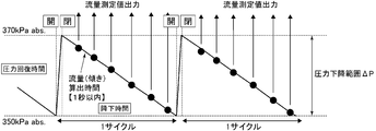
- FIG. 2 shows the pressure drop state at this time.
- the output of the measured flow rate is discontinuous because of the pressure recovery time (a) and one cycle is required. It took a few seconds to complete.
- the primary side opening / closing switching valve (upstream valve) AV is opened, the time until the pressure reaches a specified value or more is the pressure recovery time (a), and the primary side opening / closing switching valve (upstream valve).
- the time during which the pressure is lowered to a specified value or less with AV closed is the flow rate output possible time (b)
- the proportion of the time during which the flow rate can be output is determined by the proportions of (a) and (b).
- the idea is to make the internal volume V of the capacity smaller to shorten the time required for gas refilling (pressure recovery time (a)), and based on this idea, the internal volume V of the build-down capacity BC and In addition to studying whether real-time performance can be ensured by reducing the pressure difference ⁇ P during flow rate measurement, various tests were conducted on the accuracy of the flow rate monitor and its reproducibility.
- FCSs with rated flow rates F20, F200, and F600 (sccm) were prepared as pressure type flow rate control devices FCS. Further, the internal volume V of the build-down capacity BC was set to two types of about 1.78 cc and about 9.91 cc. The 9.91 cc build-down capacity BC was adjusted by adjusting the pipe length and the pipe inner diameter. Further, the detectable time (b) of the flow rate output was set to 0.5 sec (0.25 ms ⁇ 2000 points), and the test environment temperature was set to 23 ° C. ⁇ 1 ° C.
- FCS upstream pressure is set to 370 kPa abs.
- FIG. 3 shows the measurement result of the pressure recovery characteristic
- FIG. 4 is an enlarged view thereof.
- FIG. 5 shows the pressure drop characteristics at that time.
- the refilling time is achieved even at an N 2 flow rate of 100 sccm. (Pressure recovery time (a)) can be significantly shortened, and as shown in FIG. 5, it was confirmed that the measured flow rate output can be performed at intervals of at least one second.
- the opening / closing speed of the primary side opening / closing switching valve (upstream side valve) AV may have a great effect in reducing the pressure recovery time (a) relative to the flow rate output possible time (b). found. For this reason, it has been found that a piezo-driven metal diaphragm valve or an electromagnetic direct valve is desirable as the primary opening / closing switching valve (upstream valve) AV.
- shortening of the pressure recovery time (a) due to the decrease in the pressure drop range ⁇ P and the internal volume V of the build-down capacity BC leads to shortening of the pressure drop time (flow output possible time (b)). It has been found that the relationship between the measured flow rate, the internal volume V of the build-down capacity BC, and the pressure drop time (b) is particularly important.
- Table 1 shows the relationship between the measured flow rate (sccm) and the pressure drop time (sec) when the internal volume V of the builddown capacity BC is 1.78 cc.
- the internal volume V of the builddown capacity BC is In the case of 1.78 cc, it can be seen that if the flow rate is not 50 sccm or less, it is difficult to output the flow rate once or more within one second, and it is difficult to monitor the flow rate corresponding to real time.
- the pressure drop characteristic during the flow rate output possible time (b) needs to have linearity from the viewpoint of measurement error, and the pressure drop rate is constant (that is, linearity is within the range in which the flow rate can be calculated). It is limited to the range of the portion having.
- the flow measurement error due to the deviation from the linearity of the pressure drop characteristic curve was measured by measuring 5 points every 0.25 seconds when the flow measurement possible time (b) was within 1 second. That is, the internal volume V of the build-down capacity BC is 1.78 cc and 9.91 cc, the pressure drop range ⁇ P is 20 kPa abs, and the time from the closing of the primary side switching valve (upstream side valve) AV to the stabilization of the flow rate is 1 Second, the flow rate was calculated every 0.25 sec, and the error of the calculated flow rate with respect to the control flow rate was examined.
- FIGS. 9 and 10 show the results. In either case, the error can be greatly reduced by 0.25 sec or more after the primary side on-off switching valve (upstream side valve) AV is closed. understood. That is, it was confirmed that the error decreases as the pressure drop characteristic curve approaches a straight line.
- Table 2 shows the relationship between the internal volume V of the build-down capacity BC, the measured flow rate, and the pressure drop time (b).
- the internal volume V of the build-down capacity BC 1.78 cc
- the flow rate can be output at intervals within about 1 second. It can also be seen that when the internal volume V of the build-down capacity BC is 9.91 cc, the flow rate can be output at intervals of about 1 second when the flow rate is 100 to 200 sccm.
- FIG. 11 shows measurement data of flow rate accuracy when repeated measurement (10 times) is performed.
- the pressure drop time (b) is 0.5 seconds or less, the pressure drop is as shown in FIG. Since the flow rate calculation is performed within the non-linear region of the characteristic curve, it can be seen that the flow rate error tends to appear in the positive direction as shown in FIG.
- Q K ⁇ (build-down capacity ⁇ pressure drop rate ⁇ 1 / temperature)
- the present invention was created based on the results of each of the above tests, and includes a build-down type flow rate monitoring unit BDM provided on the upstream side, a pressure-type flow rate control unit FCS provided on the downstream side, and a build-down type.
- Type flow rate monitoring unit BDM and pressure type flow rate control unit FCS are connected, signal transmission circuit CT for transmitting the monitor flow rate Q of builddown type flow rate monitor unit BDM to pressure type flow rate control unit FCS, and pressure type flow rate control unit FCS And a flow rate set value adjustment mechanism QSR that adjusts the set flow rate Qs of the pressure type flow rate control unit FCS by the monitor flow rate Q from the build-down type flow rate monitor unit BDM.
- the pressure flow control unit FCS can be a flow control unit including a pressure sensor.
- the flow rate setpoint adjustment mechanism QSR has a comparator between the monitor flow rate Q and the set flow rate Qs, and automatically corrects the set flow rate Qs to the monitor flow rate Q when the difference between the monitor flow rate Q and the set flow rate Qs exceeds the set value. It can be set as the flow volume setting value adjustment mechanism of a structure.
- the build-down type flow rate monitoring unit BDM has a primary side opening / closing switching valve PV 1 that opens and closes the flow of gas from the gas supply source, and a build having a predetermined internal volume V connected to the outlet side of the primary side opening / closing switching valve PV 1 and the down capacitor BC, a temperature sensor for detecting the temperature of the gas flowing through the build-down capacity BC, the pressure sensor P 3 for detecting the pressure of gas flowing through the build-down capacity BC, the primary side switching switch valve PV It performs one opening and closing control by opening the primary opening and closing the switching valve PV 1 after the gas pressure in the build-down capacity BC to set the upper limit pressure value, after a predetermined time t s the closure of the primary side switching switch valve PV 1
- a monitor flow rate calculation control unit CPb for calculating and outputting a monitor flow rate Q by a build-down method by lowering the gas pressure to a set lower limit pressure value, (Where T is the gas temperature (° C.), V is the internal volume (l) of the build-down
- the pressure-type flow control unit FCS is a pressure-type flow control device FCS having a pressure resistance variability comprising a control valve CV, an orifice OL or a critical nozzle, a pressure gauge P 1 and / or a pressure gauge P 2 and a flow rate calculation control part CPa. It can be.
- the internal volume V of the builddown capacity BC is set to 0.5 to 20 cc
- the set upper limit pressure value is set to 400 to 100 kPa abs
- the set lower limit pressure value is set to 350 kPa abs to 50 kPa abs
- the predetermined time t is set to 0.5 to It can be within 5 seconds.
- the primary side open / close switching valve AV is a piezo-driven metal diaphragm valve or an electromagnetic direct drive type electric valve, and the gas from the set lower limit pressure value to the set upper limit pressure value due to the opening of the primary side open / close switch valve AV due to high-speed opening / closing of the valve.
- the pressure recovery time can be made significantly shorter than the gas pressure drop time from the set upper limit pressure value to the set lower limit pressure value due to the closing of the primary side opening / closing switching valve AV.
- the flow rate calculation control unit CPa of the pressure type flow rate control unit FCS and the calculation control device CPb of the builddown type flow rate monitoring unit BDM may be integrally formed.
- the build-down capacity BC is a chamber, and the chamber has a structure in which an inner cylinder and an outer cylinder are concentrically arranged and fixed, and a gap between the inner and outer cylinders forming the chamber is used as a gas flow path. It may be a configuration in which a pressure sensor P 3 in.
- a flow rate control device with a flow rate monitor, a builddown type flow rate monitor unit BDM provided on the upstream side, a pressure type flow rate control unit FCS provided on the downstream side of the builddown type flow rate monitor unit BDM, Signal transmission circuit CT that connects the build-down flow monitor BDMB and the pressure flow controller FCS, and transmits the monitor flow Q of the build-down flow monitor BDM to the pressure flow controller FCS, and pressure flow control
- the built-in flow rate monitor unit is composed of a flow rate setting value adjusting mechanism QSR that adjusts the set flow rate Qs of the pressure type flow rate control unit FCS by the monitor flow rate Q from the build-down type flow rate monitor unit BDM.
- the set flow value of the pressure flow control unit FCS is automatically adjusted by the BDM monitor flow rate.
- a build-down type flow monitor BDM is installed upstream of the pressure type flow control unit FCS, and the high response to the input side pressure fluctuation of the pressure type flow control unit is used to input the pressure type flow control unit FCS.
- a pressure drop ⁇ P corresponding to a gas pressure difference within a range in which side pressure fluctuation is allowed is generated at a rate of once or more per second in the build-down capacity BC, and the pressure drop rate ⁇ P / ⁇ t and the build.
- the pressure drop value (pressure difference ⁇ P), the pressure drop time ( ⁇ t), and the pressure drop time so that the monitor flow rate can be calculated and output at least once per second from the internal volume V of the down capacity BC and the gas temperature K.
- the internal capacity V of the build-down capacity BC is set.
- the pressure drop value (pressure difference) ⁇ P is set to about 20 to 30 kPa abs
- the pressure drop time ⁇ t is set to 0.5 to 0.8 sec
- the internal volume V of the build-down capacity BC is set to 1.8 to 18 cc.
- the pressure flow control device with flow monitor can be greatly simplified, downsized, and the manufacturing cost can be reduced. The added value of is significantly improved.
- FIG. 1 It is a schematic block diagram of the test apparatus for measuring the flow monitor characteristic of a pressure type flow control apparatus with a build-down type flow monitor. It is explanatory drawing of the pressure drop state of a builddown type
- FIG. 1 is a system diagram showing a basic configuration of a pressure type flow rate control device with a flow rate monitor according to the present invention. It is a longitudinal cross-sectional schematic diagram of the build-down type pressure type flow control apparatus with a flow monitor which concerns on this invention.
- FIG. 1 is a system diagram showing a basic configuration of a pressure type flow rate control device with a flow rate monitor according to the present invention. It is a longitudinal cross-sectional schematic diagram of the build-down type pressure type flow control apparatus with a flow monitor which concerns on this invention.
- FIG. 6 is a diagram showing the relationship between the gas flow rate sccm and the pressure drop slope kPa / sec when the measurable time is 1 second or less in each of the chambers A to E used in the examples.
- This shows the form of the pressure drop characteristic when the slope of the pressure drop in each of the chambers A to E used in this example is 20 kPa / sec.
- It is a diagram showing the relationship between the elapsed time from the closing of the primary side on / off switching valve (upstream side valve) AV of each chamber A to E used in this example and the flow rate stability.
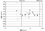
- Flow rate accuracy% S In repeated measurement of chamber A and chamber B used in this embodiment.
- P It is a diagram which shows the relationship between flow rate sccm.
- Flow rate accuracy% S In repeated measurement of chamber A and chamber B used in this embodiment.
- P It is a diagram which shows the relationship between the inclination of pressure drop, and kPa / sec of pressure drop.
- It is a basic lineblock diagram of the conventional pressure type flow control device.
- It is a basic block diagram of a conventional pressure type flow control device with a flow rate monitor.
- FIG. 12 is a system diagram showing a basic configuration of a flow rate control device with a flow rate monitor according to the present invention, and the flow rate control device with flow rate monitor connects a builddown unit BDM and a pressure type flow rate control unit FCS to each other. It is composed of a signal transmission circuit (digital communication circuit) CT.
- PV 1 is an inlet side switching valve
- PV 2 is an outlet side switching valve
- BC is a build-down capacity
- P 3 is a pressure sensor for detecting a differential pressure
- CPb is a monitor flow rate calculation control unit
- VB 2 is a monitor outlet side block.
- CV is a control valve
- CPa is a flow rate calculation control unit
- OL 1 is a small diameter orifice
- OL 2 is a large diameter orifice
- P 1 is a first pressure sensor
- P 2 is a second pressure sensor
- VB. 3 is a flow control unit inlet side block
- VB 4 is a flow control unit outlet side block
- VB 5 is a connecting block
- SK is a gasket of the connecting unit.
- the pressure type flow rate control unit FCS is provided with a set flow rate adjustment mechanism QSR, and a preset flow rate value Qs is compared with a build-down flow rate Q input via the signal transmission circuit CT and a comparator (not shown). ), The set flow rate value Qs is automatically corrected to Qs' and the flow rate control value of the pressure flow control unit FCS matches the build-down flow rate Q. Adjusted to That is, the actual flow rate is adjusted to match the builddown flow rate Q.
- the temperature detection sensor T, the filter F and the like are omitted, and the pressure type flow rate control unit FCS may be of any type, for example, one orifice.
- the basic configuration itself of the pressure type flow rate control unit FCS and the build-down type flow rate monitoring unit BDM is well known, detailed description thereof is omitted here.
- the gas having a pressure of 500 to 320 kPa abs flowing from the gas inlet 1 to the build-down type flow rate monitoring unit BDM is supplied with an inlet-side piezo switching valve PV 1 , a chamber-type build-down capacity BC, and an outlet-side piezo switching. flows in the order of the valve PV 2, monitors the flow rate Q is calculated by the monitor flow rate calculation control unit CPb, which is input to the set flow rate adjustment mechanism QSR of pressure type flow rate control unit FCS. Further, the gas flowing out from the build-down type flow rate monitoring unit BDM flows out from the gas outlet 2 through the control valve CV, the small diameter orifice OL 1 and / or the large diameter orifice OL 2 .
- the flow rate calculation control unit CPa calculates the orifice flow gas flow rate, and controls the opening / closing of the control valve CV and the opening / closing control of the orifice switching valve OLV. Further, in the set flow rate adjustment mechanism QSR of the flow rate calculation control unit CPa, the monitor flow rate Q from the build-down type flow rate monitor unit BDM and the orifice flow rate (that is, the control flow rate in the flow rate calculation control unit CPa) are compared, When the difference between the two exceeds a predetermined set value, the set flow rate Qs is adjusted so that the control flow rate of the pressure flow control unit FCS matches the monitor flow rate Q, and this is automatically corrected to Qs ′.
- build-down type flow monitor controller CPb to form the main part of the present invention, the inlet side (upstream side) piezo-off control of the switching valve PV 1, differential pressure detection pressure sensors P 3, the temperature sensor T (FIG. 12 is omitted), and the builddown flow rate Q is calculated from the volume V of the buildup capacity BC between the both switching valves PV 1 and PV 2 and the like, and this is output to the flow rate calculation control unit CPa.
- the pressure drop rate ⁇ P / ⁇ t is measured and the monitor flow rate Q is calculated by the builddown type flow rate monitor unit BDM, and the monitor flow rate calculation control unit CPb is externally connected.
- the monitor flow rate is monitored and displayed at a rate of at least once per second, and the control flow rate value of the pressure flow control unit FCS is corrected. Correction is performed automatically.
- the pressure type flow control device FCS and the build-down type flow rate monitoring unit BDM are well known, and thus detailed description thereof is omitted here. Further, the difference between the monitor flow rate output Q (flow rate output from the monitor flow rate calculation control unit CPb) and the flow rate output of the pressure type flow rate control unit FCS (flow rate output from the pressure type flow rate calculation control unit CPa) is greater than the set value. If a problem occurs, a flow rate abnormality alarm is issued, or if necessary, the flow rate self-diagnosis of the so-called pressure-type flow control device FCS can be performed to identify the cause of the flow rate abnormality and its location. In addition, when a flow rate difference equal to or greater than a set value occurs, it is possible to automatically perform zero point adjustment or the like of the pressure type flow rate control unit FCS itself.
- the inlet (upstream) side switching valve and the like are piezo-driven valves, but these may be direct-acting electromagnetically driven valves.
- the internal volume V of the build-down capacity BC is selected in the range of 1.78 to 9.91 cc.
- the pressure drop range ⁇ P is selected to be 20 kPa abs (350 to 320 kPa abs), and the monitor flow rate is output at least once per second.
- the temperature detection sensor T (not shown) is an externally attached type resistance temperature sensor, but a thermostat type thermometer inserted into the monitor inlet side block VB 1 or the monitor outlet side block VB 2 is provided. It is also possible to use it.
- the build-down capacity BC is used as the build-down capacity BC, as will be described later.
- the build-down capacity BC is formed with the internal volume of the gas flow path, It is good also as a structure which obtains the builddown capacity
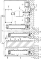
- FIG. 13 is a schematic cross-sectional view of a flow control device with a build-down type flow rate monitor according to an embodiment of the present invention.
- a chamber CH with a pressure sensor is used as the build-down capacity BC, and the inner diameters of the gas passages L 1 , L 2 , L 4 of the build-down type flow rate monitoring unit BDM are made as small as 1.8 mm.
- a second pressure sensor P 2 separately on the downstream side of the orifice OL 1, OL 2.
- a pressure sensor P 3 for and differential in the chamber CH pressure.
- a small pressure chamber CH is provided between the inlet side switching valve PV 1 and the outlet side switching valve PV 2 , and the internal volume of the pressure chamber CH is adjusted so that the builddown is performed.
- the internal volume V of the capacity BC is adjusted.
- a piezo drive metal diaphragm type normal close valve is used.
- the piezo drive metal diaphragm type normally closed valve itself is publicly known, description thereof is omitted.
- the pressure chamber CH is formed in a double cylinder of an outer cylinder CHa and an inner cylinder CHb, and a gap G between the inner and outer cylinders CHa and CHb is selected to be 1.8 mm in this embodiment.
- the internal volume of the pressure chamber CH are 1.3 to being selected to be approximately 12 cc, the configuration to which was attached a pressure sensor P 3 for differential pressure detection.
- the volume of the pressure chamber CH can be freely selected, and the gas flow passages L 1 , L 2 , L 4, etc. can all be made the same small diameter (for example, 1.8 mm ⁇ ).
- the internal volume of the build-down capacity BC can be set to a predetermined volume value accurately and easily.
- test chambers CH five chambers of the sizes shown in Table 3 with the gap G of 1.8 mm and 3.6 mm were prepared as test chambers CH, and these were applied to the test apparatus of FIG.
- the flow sensor T was stuck and fixed to the outer surface of the chamber CH.
- the volumes of the gas flow paths L 2 and L 4 other than the chamber CH are 0.226 cc.
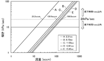
- FIG. 14 shows the relationship between the gas flow rate (sccm) and the slope of the pressure drop (kPa / sec) when the pressure drop time (b) in FIG. The results are shown, and the actual build-up capacities when assembled in the test apparatus were 2.31 cc to 15.45 cc.
- each flow rate can be measured at 25.2 sccm in chamber A, 106.6 sccm in chamber B, and 169.0 sccm in chamber E. I understand that.
- FIG. 15 shows the linearity of the pressure drop when the gas flow rate is adjusted so that the slope of the pressure drop is 20 kPa / sec in the test apparatus of FIG. It is a similar diagram. Note that the measurement data is obtained by the data logger NR in FIG.
- the flow rate measurement error due to the deviation from the linearity of the pressure drop characteristic curve is 0.25 within the flow rate measurable time (b) within 1 second. It is determined that five points are measured every second, and it can be seen that the chambers A and B having a smaller build-up capacity BC have a smaller flow rate error sooner after the pressure drop starts (that is, a straight line of the pressure drop characteristic). It can be said that it is excellent in properties).
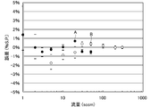
- FIG. 17 shows the results of investigating the reproducibility of the flow rate measurement accuracy for chamber A and chamber B, and is performed in the same manner as in FIG.
- the reproducibility test of the flow rate measurement accuracy in order to stabilize the slope of the pressure drop, measurement is performed after a predetermined waiting time after the primary switching valve (upstream valve) AV is closed. In order to obtain reproducibility, measurement is performed over a long period of time, and the flow rate output time is set to be within 1 second.
- Table 4 shows basic data used to create a diagram showing the reproducibility of the flow rate measurement accuracy shown in FIG. 17.
- the present invention can be widely applied not only to gas supply equipment for semiconductor manufacturing equipment but also to gas supply equipment for chemical manufacturing equipment as long as it is a pressure type flow rate control device using an orifice or a critical nozzle.
- BDM Build-down flow monitor FCS Pressure flow controller (pressure flow controller) AV Primary open / close switching valve (upstream valve) BC Builddown capacity V Internal volume RG of builddown capacity Pressure regulator N 2 N 2 supply source T Temperature sensor (resistance temperature detector) P 1 , P 2 pressure sensor P 3 differential pressure detection pressure sensor CV control valve OL orifice OL 1 small bore orifice OL 2 large bore orifice OIP external input / output circuit OLV orifice switching valve VB 1 monitor inlet side block VB 2 monitor outlet side Block VB 3 Flow rate control unit inlet side block VB 4 Flow rate control unit outlet side block VB 5 Connection portion gasket CT Signal transmission circuit (digital communication circuit) CP calculation control unit CPa flow rate calculation control unit CPb monitor flow rate calculation control unit E 1 power source for pressure flow control device E 2 power source for calculation control unit E 3 power source for solenoid valve ECV electric drive unit NR data logger S signal generator PC calculation display Part PV 1 inlet side switching valve (inlet side piezo switching valve
Landscapes
- Physics & Mathematics (AREA)
- General Physics & Mathematics (AREA)
- Fluid Mechanics (AREA)
- Engineering & Computer Science (AREA)
- Automation & Control Theory (AREA)
- Flow Control (AREA)
- Measuring Volume Flow (AREA)
Priority Applications (3)
| Application Number | Priority Date | Filing Date | Title |
|---|---|---|---|
| US14/778,398 US9791867B2 (en) | 2013-03-25 | 2014-03-17 | Flow control device equipped with flow monitor |
| KR1020157026228A KR101707877B1 (ko) | 2013-03-25 | 2014-03-17 | 유량 모니터 부착 유량 제어 장치 |
| CN201480003757.4A CN105247433B (zh) | 2013-03-25 | 2014-03-17 | 带流量监控器的流量控制装置 |
Applications Claiming Priority (2)
| Application Number | Priority Date | Filing Date | Title |
|---|---|---|---|
| JP2013-062537 | 2013-03-25 | ||
| JP2013062537A JP5847106B2 (ja) | 2013-03-25 | 2013-03-25 | 流量モニタ付圧力式流量制御装置。 |
Publications (1)
| Publication Number | Publication Date |
|---|---|
| WO2014156042A1 true WO2014156042A1 (ja) | 2014-10-02 |
Family
ID=51623059
Family Applications (1)
| Application Number | Title | Priority Date | Filing Date |
|---|---|---|---|
| PCT/JP2014/001504 WO2014156042A1 (ja) | 2013-03-25 | 2014-03-17 | 流量モニタ付流量制御装置 |
Country Status (6)
| Country | Link |
|---|---|
| US (1) | US9791867B2 (zh) |
| JP (1) | JP5847106B2 (zh) |
| KR (1) | KR101707877B1 (zh) |
| CN (1) | CN105247433B (zh) |
| TW (1) | TWI507836B (zh) |
| WO (1) | WO2014156042A1 (zh) |
Cited By (3)
| Publication number | Priority date | Publication date | Assignee | Title |
|---|---|---|---|---|
| WO2015064050A1 (ja) * | 2013-10-28 | 2015-05-07 | 株式会社フジキン | 流量計及びそれを備えた流量制御装置 |
| US10753497B2 (en) * | 2015-04-15 | 2020-08-25 | Fujikin Incorporated | Shutoff-opening device |
| TWI755704B (zh) * | 2019-05-14 | 2022-02-21 | 日商富士金股份有限公司 | 流量控制裝置、流量控制方法、流量控制裝置的控制程式 |
Families Citing this family (16)
| Publication number | Priority date | Publication date | Assignee | Title |
|---|---|---|---|---|
| CN108369425B (zh) * | 2015-12-25 | 2021-03-02 | 株式会社富士金 | 流量控制装置以及使用流量控制装置的异常检测方法 |
| US10928813B2 (en) * | 2016-03-29 | 2021-02-23 | Fujikin Incorporated | Pressure-type flow rate control device and flow rate self-diagnosis method using critical expansion condition |
| JP6767232B2 (ja) * | 2016-10-14 | 2020-10-14 | 東京エレクトロン株式会社 | 基板処理装置の流量制御器によって出力されるガスの出力流量を求める方法 |
| CN106404093A (zh) * | 2016-12-14 | 2017-02-15 | 成都秦川科技发展有限公司 | 电子远传水表及水表系统 |
| TWI612247B (zh) * | 2017-01-24 | 2018-01-21 | Huang Guo Hong | 流體控制閥 |
| JP7190186B2 (ja) * | 2017-11-30 | 2022-12-15 | 株式会社フジキン | 流量制御装置の自己診断方法 |
| CN111788534A (zh) * | 2018-02-26 | 2020-10-16 | 株式会社富士金 | 流量控制装置以及流量控制方法 |
| US11269362B2 (en) * | 2018-04-27 | 2022-03-08 | Fujikin Incorporated | Flow rate control method and flow rate control device |
| US11004711B2 (en) * | 2018-08-17 | 2021-05-11 | Taiwan Semiconductor Manufacturing Co., Ltd. | Automated wafer monitoring |
| JP2020139864A (ja) * | 2019-02-28 | 2020-09-03 | 株式会社堀場エステック | 流量算出システム、流量算出システム用プログラム、流量算出方法、及び、流量算出装置 |
| KR20210139347A (ko) * | 2019-04-25 | 2021-11-22 | 가부시키가이샤 후지킨 | 유량 제어 장치 |
| TWI774227B (zh) * | 2020-02-21 | 2022-08-11 | 日商富士金股份有限公司 | 流量控制裝置、流量控制裝置的控制方法、流量控制裝置的控制程式 |
| CN111623239A (zh) * | 2020-05-29 | 2020-09-04 | 张峰 | 一种监测低压燃气管道特征流量的方法 |
| CN112572756A (zh) * | 2020-12-11 | 2021-03-30 | 中国人民解放军63660部队 | 一种飞艇副气囊体积监测装置及方法 |
| TWI770918B (zh) * | 2021-03-31 | 2022-07-11 | 新唐科技股份有限公司 | 設定值自動調整裝置和方法 |
| CN114235302B (zh) * | 2021-11-16 | 2024-02-06 | 北京谊安医疗系统股份有限公司 | 一种通气回路泄露量的检测方法 |
Citations (6)
| Publication number | Priority date | Publication date | Assignee | Title |
|---|---|---|---|---|
| JP2000137528A (ja) * | 1998-08-24 | 2000-05-16 | Tadahiro Omi | 圧力式流量制御装置におけるオリフィス目詰検出方法およびその検出装置 |
| JP2003529218A (ja) * | 2000-03-27 | 2003-09-30 | パーカー・ハニフィン・コーポレーション | 半導体製造におけるプロセス・ガスの流量制御 |
| JP2008504613A (ja) * | 2004-07-07 | 2008-02-14 | パーカー・ハニフィン・コーポレーション | 流量制御装置および体積の内部等温制御により流量検証を行うための方法 |
| JP2009265988A (ja) * | 2008-04-25 | 2009-11-12 | Fujikin Inc | 流量自己診断機能を備えた圧力式流量制御装置の圧力制御弁用駆動回路 |
| JP2011510404A (ja) * | 2008-01-18 | 2011-03-31 | ピヴォタル システムズ コーポレーション | ガスの流量を決定する方法、ガス・フロー・コントローラの動作を決定する方法、ガスフローコントロールシステムの一部の容量を決定する方法、及びガス搬送システム |
| WO2013179550A1 (ja) * | 2012-05-31 | 2013-12-05 | 株式会社フジキン | ビルドダウン方式流量モニタ付流量制御装置 |
Family Cites Families (13)
| Publication number | Priority date | Publication date | Assignee | Title |
|---|---|---|---|---|
| US4133511A (en) * | 1977-01-26 | 1979-01-09 | Frieseke & Hoepfner Gmbh | Electro-hydraulic regulating valve system |
| JP2982003B2 (ja) | 1992-07-28 | 1999-11-22 | コマツ電子金属株式会社 | 気相成長装置および気相成長装置におけるマスフローコントローラの校正方法 |
| JP2635929B2 (ja) | 1994-04-12 | 1997-07-30 | シーケーディ株式会社 | マスフローコントローラ絶対流量検定システム |
| EP1035457B1 (en) | 1998-08-24 | 2003-10-22 | Fujikin Incorporated | Method for detecting plugging of pressure flow-rate controller and sensor used therefor |
| JP4308350B2 (ja) | 1998-11-27 | 2009-08-05 | 小林製薬株式会社 | シイタケ菌糸体抽出物を含有するlak活性スクリーニング物質およびそれを用いたlak活性スクリーニング法 |
| JP4308356B2 (ja) | 1999-01-25 | 2009-08-05 | 株式会社堀場エステック | 圧力式流量コントローラのノズル診断機構および圧力式流量コントローラのノズル診断方法 |
| JP4137666B2 (ja) | 2003-02-17 | 2008-08-20 | 株式会社堀場エステック | マスフローコントローラ |
| JP4856905B2 (ja) * | 2005-06-27 | 2012-01-18 | 国立大学法人東北大学 | 流量レンジ可変型流量制御装置 |
| JP4743763B2 (ja) * | 2006-01-18 | 2011-08-10 | 株式会社フジキン | 圧電素子駆動式金属ダイヤフラム型制御弁 |
| JP4820698B2 (ja) * | 2006-07-03 | 2011-11-24 | 株式会社フジキン | 圧力式流量制御装置の絞り機構下流側バルブの作動異常検出方法 |
| JP4933936B2 (ja) * | 2007-03-30 | 2012-05-16 | 株式会社フジキン | 圧電素子駆動式制御弁 |
| CN201062289Y (zh) * | 2007-06-01 | 2008-05-21 | 青海省高原科技发展有限公司 | 一种新型手工藏毯纺纱机纱管联接器 |
| CN103518165B (zh) * | 2011-05-10 | 2016-06-08 | 株式会社富士金 | 带有流量监测器的压力式流量控制装置 |
-
2013
- 2013-03-25 JP JP2013062537A patent/JP5847106B2/ja active Active
-
2014
- 2014-03-17 CN CN201480003757.4A patent/CN105247433B/zh not_active Expired - Fee Related
- 2014-03-17 WO PCT/JP2014/001504 patent/WO2014156042A1/ja active Application Filing
- 2014-03-17 KR KR1020157026228A patent/KR101707877B1/ko active IP Right Grant
- 2014-03-17 US US14/778,398 patent/US9791867B2/en active Active
- 2014-03-24 TW TW103110886A patent/TWI507836B/zh active
Patent Citations (6)
| Publication number | Priority date | Publication date | Assignee | Title |
|---|---|---|---|---|
| JP2000137528A (ja) * | 1998-08-24 | 2000-05-16 | Tadahiro Omi | 圧力式流量制御装置におけるオリフィス目詰検出方法およびその検出装置 |
| JP2003529218A (ja) * | 2000-03-27 | 2003-09-30 | パーカー・ハニフィン・コーポレーション | 半導体製造におけるプロセス・ガスの流量制御 |
| JP2008504613A (ja) * | 2004-07-07 | 2008-02-14 | パーカー・ハニフィン・コーポレーション | 流量制御装置および体積の内部等温制御により流量検証を行うための方法 |
| JP2011510404A (ja) * | 2008-01-18 | 2011-03-31 | ピヴォタル システムズ コーポレーション | ガスの流量を決定する方法、ガス・フロー・コントローラの動作を決定する方法、ガスフローコントロールシステムの一部の容量を決定する方法、及びガス搬送システム |
| JP2009265988A (ja) * | 2008-04-25 | 2009-11-12 | Fujikin Inc | 流量自己診断機能を備えた圧力式流量制御装置の圧力制御弁用駆動回路 |
| WO2013179550A1 (ja) * | 2012-05-31 | 2013-12-05 | 株式会社フジキン | ビルドダウン方式流量モニタ付流量制御装置 |
Cited By (4)
| Publication number | Priority date | Publication date | Assignee | Title |
|---|---|---|---|---|
| WO2015064050A1 (ja) * | 2013-10-28 | 2015-05-07 | 株式会社フジキン | 流量計及びそれを備えた流量制御装置 |
| US10073469B2 (en) | 2013-10-28 | 2018-09-11 | Fujikin Incorporated | Flow meter and flow control device provided therewith |
| US10753497B2 (en) * | 2015-04-15 | 2020-08-25 | Fujikin Incorporated | Shutoff-opening device |
| TWI755704B (zh) * | 2019-05-14 | 2022-02-21 | 日商富士金股份有限公司 | 流量控制裝置、流量控制方法、流量控制裝置的控制程式 |
Also Published As
| Publication number | Publication date |
|---|---|
| TW201506568A (zh) | 2015-02-16 |
| JP5847106B2 (ja) | 2016-01-20 |
| CN105247433A (zh) | 2016-01-13 |
| JP2014186662A (ja) | 2014-10-02 |
| KR101707877B1 (ko) | 2017-02-17 |
| CN105247433B (zh) | 2018-01-30 |
| TWI507836B (zh) | 2015-11-11 |
| US20160282880A1 (en) | 2016-09-29 |
| US9791867B2 (en) | 2017-10-17 |
| KR20150121156A (ko) | 2015-10-28 |
Similar Documents
| Publication | Publication Date | Title |
|---|---|---|
| WO2014156042A1 (ja) | 流量モニタ付流量制御装置 | |
| JP5797246B2 (ja) | 流量計及びそれを備えた流量制御装置 | |
| JP5768186B2 (ja) | ビルドダウン方式流量モニタ付流量制御装置及びこれを用いたモニタ付流量制御方法。 | |
| JP2015087110A5 (zh) | ||
| JP5727596B2 (ja) | 流量モニタ付圧力式流量制御装置の実ガスモニタ流量初期値のメモリ方法及び実ガスモニタ流量の出力確認方法 | |
| TWI470187B (zh) | Flow measurement device for flow control device for gas supply device and flow measurement method | |
| JP2020098653A (ja) | 質量流量制御装置の流量をリアルタイムで監視するシステムおよび方法 | |
| JP4137666B2 (ja) | マスフローコントローラ | |
| US20070233412A1 (en) | Mass flow rate control apparatus, its calibration method and semiconductor-producing apparatus | |
| JP2004280688A (ja) | マスフローコントローラ | |
| JP7131561B2 (ja) | 質量流量制御システム並びに当該システムを含む半導体製造装置及び気化器 | |
| TW202012887A (zh) | 氣體流量檢定單元 | |
| JP2023163311A (ja) | 流量測定装置、流量測定方法および流量制御装置の校正方法 | |
| JPH07325625A (ja) | マスフローコントローラ |
Legal Events
| Date | Code | Title | Description |
|---|---|---|---|
| 121 | Ep: the epo has been informed by wipo that ep was designated in this application |
Ref document number: 14774715 Country of ref document: EP Kind code of ref document: A1 |
|
| WWE | Wipo information: entry into national phase |
Ref document number: 14778398 Country of ref document: US |
|
| ENP | Entry into the national phase |
Ref document number: 20157026228 Country of ref document: KR Kind code of ref document: A |
|
| NENP | Non-entry into the national phase |
Ref country code: DE |
|
| 122 | Ep: pct application non-entry in european phase |
Ref document number: 14774715 Country of ref document: EP Kind code of ref document: A1 |