WO2015064050A1 - 流量計及びそれを備えた流量制御装置 - Google Patents
流量計及びそれを備えた流量制御装置 Download PDFInfo
- Publication number
- WO2015064050A1 WO2015064050A1 PCT/JP2014/005322 JP2014005322W WO2015064050A1 WO 2015064050 A1 WO2015064050 A1 WO 2015064050A1 JP 2014005322 W JP2014005322 W JP 2014005322W WO 2015064050 A1 WO2015064050 A1 WO 2015064050A1
- Authority
- WO
- WIPO (PCT)
- Prior art keywords
- flow rate
- build
- flow
- monitor
- switching valve
- Prior art date
Links
- 238000011144 upstream manufacturing Methods 0.000 claims description 39
- 238000012544 monitoring process Methods 0.000 claims description 36
- 230000007246 mechanism Effects 0.000 claims description 18
- 238000001514 detection method Methods 0.000 claims description 16
- 238000011084 recovery Methods 0.000 claims description 13
- 230000008054 signal transmission Effects 0.000 claims description 11
- 239000002184 metal Substances 0.000 claims description 6
- 229910052751 metal Inorganic materials 0.000 claims description 6
- 238000005259 measurement Methods 0.000 abstract description 21
- 238000010586 diagram Methods 0.000 description 18
- 238000012360 testing method Methods 0.000 description 14
- 238000000034 method Methods 0.000 description 11
- 238000004519 manufacturing process Methods 0.000 description 10
- 239000004065 semiconductor Substances 0.000 description 10
- 238000012937 correction Methods 0.000 description 8
- 230000007423 decrease Effects 0.000 description 5
- 239000012530 fluid Substances 0.000 description 5
- 239000003990 capacitor Substances 0.000 description 4
- 230000008859 change Effects 0.000 description 4
- 238000004891 communication Methods 0.000 description 3
- 239000013256 coordination polymer Substances 0.000 description 3
- 230000004044 response Effects 0.000 description 3
- 230000005856 abnormality Effects 0.000 description 2
- 238000000691 measurement method Methods 0.000 description 2
- 238000004904 shortening Methods 0.000 description 2
- 229910052774 Proactinium Inorganic materials 0.000 description 1
- 230000002159 abnormal effect Effects 0.000 description 1
- 230000032683 aging Effects 0.000 description 1
- 238000013459 approach Methods 0.000 description 1
- 238000013142 basic testing Methods 0.000 description 1
- 238000007796 conventional method Methods 0.000 description 1
- 230000003111 delayed effect Effects 0.000 description 1
- 238000011161 development Methods 0.000 description 1
- 230000018109 developmental process Effects 0.000 description 1
- 230000003292 diminished effect Effects 0.000 description 1
- 230000006872 improvement Effects 0.000 description 1
- 238000011835 investigation Methods 0.000 description 1
- 229910052745 lead Inorganic materials 0.000 description 1
- 230000004043 responsiveness Effects 0.000 description 1
- 238000004092 self-diagnosis Methods 0.000 description 1
- 230000006641 stabilisation Effects 0.000 description 1
- 238000011105 stabilization Methods 0.000 description 1
- 239000000126 substance Substances 0.000 description 1
- 230000009897 systematic effect Effects 0.000 description 1
Images


Classifications
-
- G—PHYSICS
- G01—MEASURING; TESTING
- G01F—MEASURING VOLUME, VOLUME FLOW, MASS FLOW OR LIQUID LEVEL; METERING BY VOLUME
- G01F1/00—Measuring the volume flow or mass flow of fluid or fluent solid material wherein the fluid passes through a meter in a continuous flow
- G01F1/05—Measuring the volume flow or mass flow of fluid or fluent solid material wherein the fluid passes through a meter in a continuous flow by using mechanical effects
- G01F1/34—Measuring the volume flow or mass flow of fluid or fluent solid material wherein the fluid passes through a meter in a continuous flow by using mechanical effects by measuring pressure or differential pressure
-
- F—MECHANICAL ENGINEERING; LIGHTING; HEATING; WEAPONS; BLASTING
- F16—ENGINEERING ELEMENTS AND UNITS; GENERAL MEASURES FOR PRODUCING AND MAINTAINING EFFECTIVE FUNCTIONING OF MACHINES OR INSTALLATIONS; THERMAL INSULATION IN GENERAL
- F16K—VALVES; TAPS; COCKS; ACTUATING-FLOATS; DEVICES FOR VENTING OR AERATING
- F16K31/00—Actuating devices; Operating means; Releasing devices
- F16K31/004—Actuating devices; Operating means; Releasing devices actuated by piezoelectric means
-
- F—MECHANICAL ENGINEERING; LIGHTING; HEATING; WEAPONS; BLASTING
- F16—ENGINEERING ELEMENTS AND UNITS; GENERAL MEASURES FOR PRODUCING AND MAINTAINING EFFECTIVE FUNCTIONING OF MACHINES OR INSTALLATIONS; THERMAL INSULATION IN GENERAL
- F16K—VALVES; TAPS; COCKS; ACTUATING-FLOATS; DEVICES FOR VENTING OR AERATING
- F16K31/00—Actuating devices; Operating means; Releasing devices
- F16K31/02—Actuating devices; Operating means; Releasing devices electric; magnetic
- F16K31/06—Actuating devices; Operating means; Releasing devices electric; magnetic using a magnet, e.g. diaphragm valves, cutting off by means of a liquid
-
- G—PHYSICS
- G01—MEASURING; TESTING
- G01F—MEASURING VOLUME, VOLUME FLOW, MASS FLOW OR LIQUID LEVEL; METERING BY VOLUME
- G01F1/00—Measuring the volume flow or mass flow of fluid or fluent solid material wherein the fluid passes through a meter in a continuous flow
- G01F1/05—Measuring the volume flow or mass flow of fluid or fluent solid material wherein the fluid passes through a meter in a continuous flow by using mechanical effects
- G01F1/34—Measuring the volume flow or mass flow of fluid or fluent solid material wherein the fluid passes through a meter in a continuous flow by using mechanical effects by measuring pressure or differential pressure
- G01F1/36—Measuring the volume flow or mass flow of fluid or fluent solid material wherein the fluid passes through a meter in a continuous flow by using mechanical effects by measuring pressure or differential pressure the pressure or differential pressure being created by the use of flow constriction
- G01F1/363—Measuring the volume flow or mass flow of fluid or fluent solid material wherein the fluid passes through a meter in a continuous flow by using mechanical effects by measuring pressure or differential pressure the pressure or differential pressure being created by the use of flow constriction with electrical or electro-mechanical indication
-
- G—PHYSICS
- G01—MEASURING; TESTING
- G01F—MEASURING VOLUME, VOLUME FLOW, MASS FLOW OR LIQUID LEVEL; METERING BY VOLUME
- G01F1/00—Measuring the volume flow or mass flow of fluid or fluent solid material wherein the fluid passes through a meter in a continuous flow
- G01F1/05—Measuring the volume flow or mass flow of fluid or fluent solid material wherein the fluid passes through a meter in a continuous flow by using mechanical effects
- G01F1/34—Measuring the volume flow or mass flow of fluid or fluent solid material wherein the fluid passes through a meter in a continuous flow by using mechanical effects by measuring pressure or differential pressure
- G01F1/36—Measuring the volume flow or mass flow of fluid or fluent solid material wherein the fluid passes through a meter in a continuous flow by using mechanical effects by measuring pressure or differential pressure the pressure or differential pressure being created by the use of flow constriction
- G01F1/40—Details of construction of the flow constriction devices
- G01F1/42—Orifices or nozzles
-
- G—PHYSICS
- G01—MEASURING; TESTING
- G01F—MEASURING VOLUME, VOLUME FLOW, MASS FLOW OR LIQUID LEVEL; METERING BY VOLUME
- G01F1/00—Measuring the volume flow or mass flow of fluid or fluent solid material wherein the fluid passes through a meter in a continuous flow
- G01F1/68—Measuring the volume flow or mass flow of fluid or fluent solid material wherein the fluid passes through a meter in a continuous flow by using thermal effects
- G01F1/684—Structural arrangements; Mounting of elements, e.g. in relation to fluid flow
- G01F1/6847—Structural arrangements; Mounting of elements, e.g. in relation to fluid flow where sensing or heating elements are not disturbing the fluid flow, e.g. elements mounted outside the flow duct
-
- G—PHYSICS
- G01—MEASURING; TESTING
- G01F—MEASURING VOLUME, VOLUME FLOW, MASS FLOW OR LIQUID LEVEL; METERING BY VOLUME
- G01F15/00—Details of, or accessories for, apparatus of groups G01F1/00 - G01F13/00 insofar as such details or appliances are not adapted to particular types of such apparatus
- G01F15/001—Means for regulating or setting the meter for a predetermined quantity
- G01F15/002—Means for regulating or setting the meter for a predetermined quantity for gases
-
- G—PHYSICS
- G01—MEASURING; TESTING
- G01F—MEASURING VOLUME, VOLUME FLOW, MASS FLOW OR LIQUID LEVEL; METERING BY VOLUME
- G01F15/00—Details of, or accessories for, apparatus of groups G01F1/00 - G01F13/00 insofar as such details or appliances are not adapted to particular types of such apparatus
- G01F15/005—Valves
-
- G—PHYSICS
- G01—MEASURING; TESTING
- G01F—MEASURING VOLUME, VOLUME FLOW, MASS FLOW OR LIQUID LEVEL; METERING BY VOLUME
- G01F15/00—Details of, or accessories for, apparatus of groups G01F1/00 - G01F13/00 insofar as such details or appliances are not adapted to particular types of such apparatus
- G01F15/02—Compensating or correcting for variations in pressure, density or temperature
- G01F15/04—Compensating or correcting for variations in pressure, density or temperature of gases to be measured
-
- G—PHYSICS
- G05—CONTROLLING; REGULATING
- G05D—SYSTEMS FOR CONTROLLING OR REGULATING NON-ELECTRIC VARIABLES
- G05D7/00—Control of flow
- G05D7/06—Control of flow characterised by the use of electric means
- G05D7/0617—Control of flow characterised by the use of electric means specially adapted for fluid materials
- G05D7/0629—Control of flow characterised by the use of electric means specially adapted for fluid materials characterised by the type of regulator means
- G05D7/0635—Control of flow characterised by the use of electric means specially adapted for fluid materials characterised by the type of regulator means by action on throttling means
- G05D7/0641—Control of flow characterised by the use of electric means specially adapted for fluid materials characterised by the type of regulator means by action on throttling means using a plurality of throttling means
- G05D7/0647—Control of flow characterised by the use of electric means specially adapted for fluid materials characterised by the type of regulator means by action on throttling means using a plurality of throttling means the plurality of throttling means being arranged in series
Definitions
- the present invention relates to an improvement of a flow rate control device with a flow rate monitor.
- a flow rate control device having a pressure resistance variation characteristic and a build-down type flow rate monitor
- the control flow rate by the flow rate control device is increased.
- the build-down capacity of the build-down flow monitor can be switched appropriately according to the flow area of the fluid to be controlled, enabling high-accuracy flow monitoring over a wide flow area.
- the present invention relates to a flow rate switching device with a flow range switching type build-down type flow meter and a flow rate range switching type flow rate monitor.
- thermal flow control devices MFC and pressure flow control devices FCS have been widely used in gas supply devices for semiconductor manufacturing equipment.
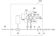
- the latter pressure type flow rate control device FCS has a control valve CV, a temperature detector T, a pressure detector P, an orifice OR, a temperature correction / flow rate calculation circuit CDa, and a comparison circuit CDb.
- the detected values from the pressure detector P and the temperature detector T are input to the temperature correction / flow rate calculation circuit CDa, where temperature correction and flow rate calculation of the detected pressure are performed.
- the flow rate calculation value Qt is input to the comparison circuit CDb.
- An input signal Q S corresponding to the set flow rate is input from the terminal In and input to the comparison circuit CDb via the input / output circuit CDc, where it is compared with the flow rate calculation value Qt from the temperature correction / flow rate calculation circuit CDa. Is done.
- the control signal Pd is output to the drive portion of the control valve CV.
- the control valve CV is driven in the closing direction, and is driven in the closing direction until the difference (Qs ⁇ Qt) between the set flow rate input signal Qs and the calculated flow rate value Qt becomes zero.
- FIG. 21 shows an example of a conventional flow rate monitor
- the flow rate control device with flow rate monitor 20 is a combination of a thermal mass flow rate sensor 25 and a pressure type flow rate control device.
- the first pressure sensor 27a, the open / close control valve 24, the thermal mass flow sensor 25, the second pressure sensor 27b, the throttle unit (sonic nozzle) 26, and the calculation control unit 28a are used to detect the inlet side pressure. And an input / output circuit 28b and the like.
- the thermal mass flow sensor 25 includes a rectifier 25a, a branch flow path 25b that branches a flow rate of a predetermined ratio F / A from the flow path 23, and a sensor body 25c provided in the branch flow path 25b.
- a flow rate signal Sf indicating the flow rate F is output to the arithmetic control unit 28a.
- the restrictor 26 is a sonic nozzle that allows a fluid having a flow rate proportional to the upstream pressure to flow when the pressure difference between the upstream side and the downstream side is equal to or greater than a predetermined value (that is, under critical conditions). Is a pressure signal, Pa and Pb are pressures, F is a total flow rate, Sf is a flow rate signal, and Cp is a valve opening control signal.
- the arithmetic control unit 28a feedback-controls the on-off valve 24 by feeding back the pressure signals Spa and Spb from the pressure sensors 27a and 27b and the flow rate signal Sf from the flow rate sensor 25 and outputting the valve opening degree control signal Cp. . That is, the flow rate setting signal Fs is input from the input / output circuit 28b to the arithmetic control unit 28a, and the flow rate F of the fluid flowing through the mass flow rate control device 20 is adjusted to become the flow rate setting signal Fs. More specifically, the calculation control unit 28a controls the flow rate F of the fluid flowing through the sonic nozzle 26 by performing feedback control of the opening / closing control valve 24 using the output (pressure signal Spb) of the second pressure sensor 27b. At the same time, the actual flow rate F is measured using the output (flow rate signal Sf) of the thermal flow rate sensor 25 at this time, and the operation of the mass flow rate control device 20 is confirmed.
- the flow rate control device 20 with a flow rate monitor in FIG. 21 performs pressure type flow rate control for adjusting the opening degree of the open / close control valve 24 using the pressure signal Spb of the second pressure sensor 27b and monitoring of the actual flow rate. Since both the flow rate measurement using the thermal flow sensor 25 to be performed is incorporated in the arithmetic control unit 28a, it is determined whether or not the control flow rate gas corresponding to the set flow rate Fs is actually flowing, that is, the control flow rate and the actual flow rate. It is possible to easily and surely monitor whether there is a difference between and in real time, and to achieve a high practical utility.
- the first problem is that when a difference occurs between the monitor flow rate value (actual flow rate value) and the control flow rate value, the occurrence of the difference can be detected by an alarm or the like, but automatically. Since the control flow rate value cannot be corrected, that is, the set flow rate value Fs cannot be adjusted, if the correction of the control flow rate value is delayed due to any cause, such as the absence of operating personnel, the gas with a flow rate different from the set flow rate value ( The supply of the actual flow rate gas) will be continued, and various inconveniences will occur in semiconductor manufacturing.
- the second problem is that there are two different measurement methods: pressure flow measurement using the second pressure sensor 27b for flow control and flow measurement using the thermal flow sensor 25 for flow monitoring. Since it is incorporated, the structure of the flow rate control device 20 with a flow rate monitor becomes complicated, and the size of the device cannot be reduced and the manufacturing cost cannot be reduced.
- the third problem is that the arithmetic control unit 28a controls the opening / closing control valve 24 using both the output Spb of the second pressure sensor 27b and the flow output Sf of the thermal flow sensor 25, and the first pressure sensor.
- the flow rate output Sf of the thermal flow sensor 25 is corrected using the output Spa of the 27a.
- the two pressure signals of the first pressure sensor 27a and the second pressure sensor 27b and the flow rate signal from the thermal flow sensor 25 are The opening / closing control of the opening / closing control valve 24 is performed using these three signals. For this reason, there is a problem that not only the configuration of the arithmetic control unit 28a is complicated, but also the stable flow rate control characteristics and excellent high responsiveness as the pressure type flow rate control device FCS are reduced.
- the present inventors integrally combined the pressure type flow control device FCS and the build-down type flow measurement unit provided on the upstream side of the pressure type flow control device FCS. Operate the build-down type flow rate measuring unit within the pressure fluctuation range allowed for the side pressure (input side pressure), and build-down type flow rate measurement at least once within 1 second (preferably multiple times per second) By sending a flow rate monitor signal from the control unit, the flow rate control by the pressure type flow rate control device can be performed simultaneously with the flow rate monitor substantially similar to the real monitor by the build-down type flow rate measurement unit.
- the flow rate setting value on the pressure flow control device is automatically adjusted, and the flow control value by the pressure flow control device is measured as a build-down flow measurement.
- this newly developed pressure-type flow control device with build-down type flow rate monitor makes full use of the flow-rate characteristics of the pressure-type flow control device that the flow control characteristics are hardly affected by pressure fluctuations on the input side.
- flow monitoring by the build-down flow monitoring unit can be performed in a near real-time situation (at least once per second), and the calculation control unit is simplified and the device main unit is greatly reduced in size. This makes it possible to improve gas replacement properties.
- FIG. 5 is a schematic configuration diagram of a test apparatus for measuring the flow monitor characteristics of a pressure-type flow control apparatus with a build-down type flow monitor, and the present inventors have used the test apparatus to produce a pressure-type flow control apparatus.
- a basic test for builddown flow rate measurement was performed in which the flow rate was calculated from the slope of the pressure drop between the FCS and the primary side open / close switching valve (upstream side valve) AV.
- N 2 is a gas supply source
- RG is a pressure regulator
- ECV is an electromagnetic drive unit
- AV is a primary side opening / closing switching valve (upstream valve)
- FCS is a pressure flow control device
- VP Vacuum pump
- BC is a build-down capacity
- T is a temperature sensor
- P is a pressure sensor provided on the primary side of a control valve in the pressure type flow control device
- FCS P 0 is a pressure sensor output
- E is a power supply unit
- E 1 the pressure type flow rate control apparatus for a power supply
- E 2 is the power supply operation control unit
- E 3 is the power supply for the primary side switching valve (upstream valve)
- S is the signal generator
- CP is the arithmetic control unit
- CPa the pressure type A flow rate calculation control unit
- CPb is a builddown monitor flow rate calculation control unit
- PC is a calculation display unit
- NR is a data logger.
- the build-down capacity BC corresponds to the volume of the duct space between the outlet side of the primary side open / close switching valve (upstream side valve) AV and the inlet side of the control valve (not shown) of the pressure type flow control device FCS.
- the internal volume V of the build-down capacity BC is 1.78 cc by adjusting the length and inner diameter of the pipe line, or adjusting the internal volume of a build-down chamber (not shown) interposed in the pipe line.
- the volume can be adjusted to 9.91 cc, 4.6 to 11.6 cc, and 1.58 to 15.31 cc.
- the inner diameter of the flow path between the outlet of the primary on-off switching valve (upstream valve) AV and the inlet of the control valve CV is 1.8 mm, and the contents of the build-down capacity BC
- the product V is selected from 1.58 to 15.31 cc.
- the monitor flow rate is calculated using the pressure drop rate in the build-down capacity BC as will be described later, and the pressure-type flow rate calculation control unit CPa is further calculated. Then, similar to the control calculation unit of the conventional pressure type flow rate control device FCS, calculation of the flow rate through the orifice (not shown), opening / closing control of the control valve (not shown), and the like are performed.
- the pressure type flow control device FCS the primary side opening / closing switching valve (upstream side valve) AV, the pressure regulator RG, and other devices are all known ones, and the description thereof is omitted here.
- a piezo-driven metal diaphragm valve is used, but a direct acting solenoid valve or a pilot solenoid valve is used. It may be an air operated valve provided.
- the reason why the build-down type flow rate measuring unit can be arranged on the upstream side of the pressure type flow rate control device FCS is that the pressure type flow rate control device FCS using the orifice is not easily affected by fluctuations in the gas supply pressure as described above. Further, it is well known that the flow rate can be measured with high accuracy by the build-down method.
- the flow rate Q flowing through the build-down capacity BC with the internal volume V (l) can be calculated by the following equation (1).
- V is the internal volume (l) of the build-down capacity BC
- ⁇ P / ⁇ t is the pressure drop rate in the build-down capacity V
- T is the gas temperature (° C.).
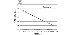
- the pressure flow control device FCS has an upstream pressure of 400 kPa abs, a pressure drop (pressure difference ⁇ P) of 50 kPa ⁇ abs or more, and an internal volume V of the build-down capacity BC of 4.6 to The flow rate was measured by a build-down method at 11.6 cc.
- FIG. 6 shows the pressure drop state at this time.
- the output of the measured flow rate becomes discontinuous because of the pressure recovery time (a), and one cycle is shown. It took a few seconds to complete.
- the primary side opening / closing switching valve (upstream valve) AV is opened, the time until the pressure reaches a specified value or more is the pressure recovery time (a), and the primary side opening / closing switching valve (upstream valve).
- the time during which the pressure is lowered to a specified value or less with AV closed is the flow rate output possible time (b)
- the proportion of the time during which the flow rate can be output is determined by the proportions of (a) and (b).
- the idea is to make the internal volume V of the capacity smaller to shorten the time required for gas refilling (pressure recovery time (a)), and based on this idea, the internal volume V of the build-down capacity BC and In addition to studying whether real-time performance can be ensured by reducing the pressure difference ⁇ P during flow rate measurement, various tests were conducted on the accuracy of the flow rate monitor and its reproducibility.
- FCS with rated flow rates F20, F200, and F600 are prepared as the pressure type flow rate control device FCS of the test apparatus of FIG. 5, and the internal volume V of the build-down capacity BC is about 1
- FCS pressure type flow rate control device
- V of the build-down capacity BC is about 1
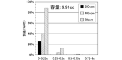
- the 9.91 cc build-down capacity BC was adjusted by adjusting the pipe length and the pipe inner diameter.
- the detectable time (b) of the flow rate output was set to 0.5 sec (0.25 ms ⁇ 2000 points), and the test environment temperature was set to 23 ° C. ⁇ 1 ° C.
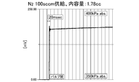
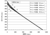
- FIG. 7 shows the measurement results of the pressure recovery characteristics
- FIG. 8 is an enlarged view thereof
- FIG. 9 shows the pressure drop characteristics at that time.
- the refill time at the N 2 flow rate of 100 SCCM is reduced by reducing the internal volume V of the build-down capacity BC to 1.78 cc and the pressure drop range ⁇ P to 20 kPa abs. It was confirmed that the pressure recovery time (a)) can be significantly shortened, and the measured flow rate can be output at intervals of at least 1 second, as shown in FIG.
- the opening / closing speed of the primary side opening / closing switching valve (upstream side valve) AV has a great influence in reducing the pressure recovery time (a) with respect to the flow rate output possible time (b). For this reason, it has been found that a piezo-driven metal diaphragm valve or an electromagnetic direct valve is desirable as the primary opening / closing switching valve (upstream valve) AV. Furthermore, shortening of the pressure recovery time (a) due to the decrease in the pressure drop range ⁇ P and the internal volume V of the build-down capacity BC leads to shortening of the pressure drop time (flow output possible time (b)). It has been found that the relationship between the measured flow rate, the internal volume V of the build-down capacity BC, and the pressure drop time (b) is particularly important.
- Table 1 shows the relationship between the measured flow rate (SCCM) and the pressure drop time (sec) when the internal volume V of the builddown capacity BC is 1.78 cc.
- the internal volume V of the builddown capacity BC is In the case of 1.78 cc, it can be seen that if the flow rate is not less than 50 SCCM, it is difficult to output the flow rate once or more within one second, and it is difficult to monitor the flow rate corresponding to real time.
- the pressure drop characteristic during the flow rate output possible time (b) needs to have linearity from the viewpoint of measurement error, and the pressure drop rate is constant (that is, linearity is within the range in which the flow rate can be calculated). It was found to be limited to the range of the portion having
- FIG. 10 to FIG. 12 show the results of investigating the form of the pressure drop characteristic when the measured flow rate is 100, 50 and 10 SCCM.
- the pressure drop characteristic is immediately after the builddown. Loss of linearity.
- the build-down capacity BC is 1.78 cc
- the fluid is N 2 gas.
- the flow measurement error due to the deviation from the linearity of the pressure drop characteristic curve was measured by measuring 5 points every 0.25 seconds when the flow measurement possible time (b) was within 1 second. That is, the internal volume V of the build-down capacity BC is 1.78 cc and 9.91 cc, the pressure drop range ⁇ P is 20 kPa abs, and the time from the closing of the primary side switching valve (upstream side valve) AV to the stabilization of the flow rate is 1 Second, the flow rate was calculated every 0.25 sec, and the error of the calculated flow rate with respect to the control flow rate was examined.
- FIG. 13 and FIG. 14 show the results.
- the error can be greatly reduced by 0.25 sec or more after the primary side open / close switching valve (upstream side valve) AV is closed. understood. That is, it was confirmed that the error decreases as the pressure drop characteristic curve approaches a straight line.
- Table 2 shows the relationship between the internal volume V of the build-down capacity BC, the measured flow rate, and the pressure drop time (b).
- the internal volume V of the build-down capacity BC 1.78 cc
- the flow rate can be output at intervals of about 1 second. It can also be seen that when the internal volume V of the build-down capacity BC is 9.91 cc, the flow rate can be output at intervals of about 1 second when the flow rate is 100 to 200 SCCM.
- FIG. 15 is a system diagram showing a basic configuration of a pressure-type flow control device with a flow rate monitor developed by the present inventors based on the results of the above tests.
- the build-down unit BDM, the pressure type flow rate control unit FCS, and a signal transmission circuit (digital communication circuit) CT connecting the two are configured.
- PV 1 is an inlet side switching valve
- PV 2 is an outlet side switching valve
- BC is a build-down capacity
- P 3 is a pressure sensor
- CPb is a monitor flow rate calculation control unit
- VB 1 is a monitor inlet side. block
- VB 2 is a monitor outlet side block.
- CV is a control valve
- CPa is a flow rate calculation control unit
- OR 1 is a small diameter orifice
- OR 2 is a large diameter orifice
- P 1 is a first pressure sensor
- P 2 is a second pressure sensor
- VB. 3 is a flow control unit inlet side block
- VB 4 is a flow control unit outlet side block
- VB 5 is a connecting block
- SK is a gasket of the connecting unit.
- the pressure type flow rate control unit FCS is provided with a set flow rate adjusting mechanism QRS, and a preset flow rate value Qs inputted through the signal transmission circuit CT and a comparator (not shown).
- the set flow rate value Qs is automatically corrected to Qs ′ so that the flow rate control value of the pressure type flow rate control unit FCS matches the build-down flow rate Q. Adjusted. That is, the actual flow rate is adjusted to match the builddown flow rate Q.
- the temperature detection sensor T, the filter F and the like are omitted, and the pressure type flow rate control unit FCS may be of any type, for example, one orifice. It is. Further, since the basic configuration itself of the pressure type flow rate control unit FCS and the builddown type flow rate monitoring unit BDM is known, detailed description thereof is omitted here.
- the gas having a pressure of 500 to 320 kPa abs flowing from the gas inlet 1 into the builddown type flow rate monitoring unit BDM is supplied with an inlet side piezo switching valve PV 1 , a chamber type builddown capacity BC, and an outlet side piezo switching valve PV. 2
- the monitor flow rate calculation control unit CPb calculates the monitor flow rate Q, and this is input to the set flow rate adjustment mechanism QSR of the pressure type flow rate control unit FCS.
- the gas flowing out from the build-down type flow rate monitoring unit BDM flows out from the gas outlet 2 through the control valve CV, the small diameter orifice OR 1 and / or the large diameter orifice OR 2 .
- the flow rate calculation control unit CPa calculates the orifice circulation gas flow rate, and controls the opening / closing control of the control valve CV and the opening / closing control of the orifice switching valve OLV. Further, in the set flow rate adjustment mechanism QSR of the flow rate calculation control unit CPa, the monitor flow rate Q from the build-down type flow rate monitor unit BDM and the orifice flow rate (that is, the control flow rate in the flow rate calculation control unit CPa) are compared. When the difference between the two exceeds a predetermined set value, the set flow rate Qs is adjusted so that the control flow rate of the pressure type flow rate control unit FCS matches the monitor flow rate Q, and this is automatically corrected to Qs ′.
- build-down type flow monitor controller CPb to form the main part of the present invention, opening and closing control of the inlet side (upstream side) piezoelectric switching valve PV 1 and a pressure sensor P 3, omitted in the temperature sensor T (FIG. 15 ) And the volume V of the build-down capacity BC between the switching valves PV 1 and PV 2 , etc., and the build-down flow rate Q is calculated and output to the flow rate calculation control unit CPa.
- the pressure drop rate ⁇ P / ⁇ t is measured and the monitor flow rate Q is calculated by the builddown type flow rate monitor unit BDM, and the monitor flow rate calculation control unit CPb
- the monitor flow rate is monitored and displayed at a rate of at least once per second, and the control flow rate value of the pressure type flow rate control unit FCS is displayed. Correction and correction are automatically performed.
- the difference between the monitor flow rate output Q (flow rate output from the monitor flow rate calculation control unit CPb) and the flow rate output of the pressure type flow rate control unit FCS (flow rate output from the pressure type flow rate calculation control unit CPa) is greater than the set value. If a problem occurs, a flow rate abnormality alarm is issued, or if necessary, the flow rate self-diagnosis of the so-called pressure-type flow control device FCS can be performed to identify the cause of the flow rate abnormality and its location. In addition, when a flow rate difference equal to or greater than a set value occurs, it is possible to automatically perform zero point adjustment or the like of the pressure type flow rate control unit FCS itself.
- the inlet side switching valve or the like is a piezo drive valve, but these may be a direct acting electromagnetic drive valve.
- the internal volume V of the build-down capacity BC is selected in the range of 1.78 to 9.91 cc.
- the pressure drop range ⁇ P is selected to be 20 kPa abs (350 to 320 kPa abs), and the monitor flow rate is output at least once per second.
- the temperature detection sensor T (not shown) is an externally attached resistance temperature sensor, but a thermostat thermometer inserted into the monitor block VB 1 or VB 2 can also be used. .
- a chamber with a pressure sensor is used as the build-down capacity BC as will be described later, but the build-down capacity BC is formed by the internal volume of the gas flow path, It is good also as a structure which obtains the builddown capacity
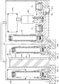
- FIG. 16 is a schematic cross-sectional view of the pressure type flow control device with a build-down type flow rate monitor of FIG.
- a chamber CH with a pressure sensor is used as the build-down capacity BC, and the inner diameters of the gas passages L 1 , L 3 , L 5 of the build-down type flow rate monitoring unit BDM are 1.8 mm.
- a second pressure sensor P 2 separately on the downstream side of the orifice OR 1, OR 2.
- a pressure sensor P 3 in the chamber CH is provided.
- a small pressure chamber CH between the inlet-side switching valve PV 1 and the outlet side switching valve PV 2 by adjusting the internal volume of the pressure chamber CH, the build-down capacity It is set as the structure which adjusts the internal volume V of BC.
- a piezo drive metal diaphragm type normal close valve is used in order to increase the opening / closing speed of both switching valves PVV 1 and PV 2 .
- the piezo drive metal diaphragm type normally closed valve itself is publicly known, description thereof is omitted.
- the pressure chamber CH is formed in a double cylinder of an outer cylinder CHa and an inner cylinder CHb, and a gap G between the inner and outer cylinders CHa and CHb is selected to be 1.8 mm in this embodiment.
- the internal volume of the pressure chamber CH is selected to be approximately 1.3 ⁇ 12 cc, it has a configuration that attaching a pressure sensor P 3 thereto.
- the volume of the pressure chamber CH can be freely selected, and the gas flow passages L 1 , L 2 , L 4, etc. are all made the same small diameter (for example, 1.8 mm ⁇ ). Therefore, the internal volume of the build-down capacity BC can be set to a predetermined volume value accurately and easily.
- test chambers CH five chambers of the sizes shown in Table 3 with the gap G of 1.8 mm and 3.6 mm were prepared as test chambers CH, and these were applied to the test apparatus of FIG.
- the flow sensor T was stuck and fixed to the outer surface of the chamber CH.
- the volumes of the gas flow paths L 3 and L 5 other than the chamber CH are 0.226 cc.
- FIG. 17 shows the relationship between the gas flow rate (SCCM) and the slope of pressure drop (kPa / sec) when the pressure drop time (b) in FIG.
- SCCM gas flow rate
- kPa / sec slope of pressure drop
- each flow rate can be measured at 25.2 sccm in chamber A, 106.6 sccm in chamber B, and 169.0 sccm in chamber E. I understand that.
- the flow rate setting value adjusting mechanism QSR that adjusts the set flow rate Qs of the pressure type flow rate control unit FCS by the monitor flow rate Q from the builddown type flow rate monitor unit BDM, and the monitor flow rate of the builddown type flow rate monitor unit BDM
- the set flow rate value of the pressure type flow rate control unit FCS is automatically adjusted.
- a build-down type flow rate monitoring unit BDM is installed upstream of the pressure type flow rate control unit FCS, and the high response to the input side pressure fluctuation of the pressure type flow rate control unit is utilized to input the pressure type flow rate control unit FCS.
- a pressure drop ⁇ P corresponding to a gas pressure difference within a range in which side pressure fluctuation is allowed is generated at a rate of once or more per second in the build-down capacity BC, and the pressure drop rate ⁇ P / ⁇ t and the build
- the pressure drop value (pressure difference ⁇ P), the pressure drop time ( ⁇ t), and the pressure drop time so that the monitor flow rate can be calculated and output at least once per second from the internal volume V of the down capacity BC and the gas temperature K.
- the internal capacity V of the build-down capacity BC is set.
- the pressure drop value (pressure difference) ⁇ P is set to approximately 20 to 30 kPa abs
- the pressure drop time ⁇ t is set to 0.5 to 0.8 sec
- the internal volume V of the builddown capacity BC is set to 1.8 to 18 cc.
- the pressure flow control device with flow monitor can be greatly simplified, downsized, and the manufacturing cost can be reduced. The added value of is significantly improved.
- the device cannot automatically correct the set value of the control flow even if the actual flow rate is found to be abnormal, causing various inconveniences due to the delay in the flow rate correction, simplifying the structure of the flow control device itself, If downsizing becomes difficult, and in addition, the excellent response characteristics and stable flow control characteristics of the pressure-type flow control device are diminished, and (c) build-down when the control flow changes significantly.
- a build-down type flow rate measuring unit provided on the upstream side is integrally combined, and the build-down type flow rate measuring unit is within the pressure fluctuation range allowed for the upstream side pressure (input side pressure) of the flow control device.
- the flow rate can be monitored easily and with high accuracy in the large flow area and small flow area.
- the flow rate setting value on the pressure type flow control device side is automatically adjusted, and the flow rate control value by the pressure type flow control device is measured by the build-down type flow rate measurement.
- a flow control device with a flow rate range switching type flow rate monitor was set to modify the flow value.
- the flow rate monitor by the build-down type flow rate monitor unit is almost real time (at least once). / 1 second), and it has made it possible to simplify the calculation control unit, expand the control flow rate range, greatly reduce the size of the device main unit, and improve gas replacement properties. It is intended to provide a flow range switching type build-down type flow meter and a flow range switching type flow control device with a flow monitor.
- a flow meter according to the present invention was created based on the results of the above tests, and the invention of claim 1 is directed to an inlet-side opening / closing switching valve PV disposed on a flow path. 1 and an outlet side opening / closing switching valve PV 2 arranged downstream of the inlet side switching valve PV 1 and a control valve CV arranged downstream of the outlet side switching valve PV 2.
- the control valve CV may be a control valve CV inside the flow rate control unit FCS. Further, a plurality of flow paths having an internal volume divided by the open / close switching valve are arranged.
- the flow control device includes, as a first means, a build-down type flow monitor BDM provided on the upstream side and a flow control unit FCS provided on the downstream side of the build-down type flow monitor.
- the build-down type flow monitor BDM is an inlet-side opening and closing the switching valve PV 1
- build-down capacitance BC which is provided on the downstream side of the inlet-side opening and closing the switching valve
- the build-down capacitance BC A temperature sensor Th provided in the downstream gas passage, an outlet side on / off switching valve PV 2 provided on the downstream side of the builddown capacity BC, a pressure sensor P 3 provided on the downstream side of the outlet side on / off switching valve, and a monitor flow rate calculation control unit CPb
- the detection value of the temperature sensor Th and a pressure sensor P 3 is input by the monitoring flow rate calculation control unit CPb, the outlet side of the inlet-side opening and closing the switching valve PV 1 and flow controller FC
- the flow rate control device is the first means, wherein the build-down type flow rate monitoring unit BDM is connected to the flow rate control unit FCS by the signal transmission circuit CT, and the monitor flow rate Q of the build-down type flow rate monitoring unit BDM is connected.
- the flow rate control unit FCS is provided with a flow rate setting value adjustment mechanism QSR that adjusts the set flow rate Qs of the flow rate control unit FCS with the monitor flow rate Q from the build-down type flow rate monitor unit BDM. May be.
- the flow control device includes, as a second means, a build-down flow monitor BDM provided on the upstream side, and a flow control FCS provided downstream of the build-down flow monitor.
- a signal transmission circuit CT that connects the builddown type flow rate monitoring unit BDM and the flow rate control unit FCS, and transmits the monitor flow rate Q of the builddown type flow rate monitoring unit BDM to the flow rate control unit FCS, and the flow rate control unit FCS.
- a flow rate control device comprising a flow rate set value adjustment mechanism QSR that adjusts the set flow rate Qs of the flow rate control unit FCS by the monitor flow rate Q from the build-down type flow rate monitor unit BDM,
- the inlet side on / off switching valve PV 1 for opening and closing the flow of gas from the gas supply source, and a predetermined internal capacity connected to the outlet side of the inlet side on / off switching valve PV 1
- the flow rate control device includes a flow rate set value adjusting mechanism GSR, a comparator of the monitor flow rate Q and the set flow rate Qs, and the monitor flow rate Q and the set flow rate Qs. If the difference exceeds the set value, the flow rate set value adjustment mechanism may be configured to automatically correct the set flow rate Qs to the monitor flow rate Q.
- the flow control device sets the builddown volume V to 0.5 to 20 cc, sets the upper limit pressure value to 400 to 100 kPa abs, and sets the lower limit pressure value to 350 kPa abs. Further, the predetermined time t may be set within 0.5 to 5 seconds at ⁇ 50 kPa abs.
- the large flow rate monitor flow rate range may be 40 to 600 SCCM, and the low flow rate monitor flow rate range may be 1 to 50 SCCM.
- the inlet-side opening and closing the switching valve PV 1 with a piezo-driven metal diaphragm valve or an electromagnetic linear type electric valve, the inlet by fast opening and closing of the valve
- the recovery time of the gas pressure from the set lower limit pressure value to the set upper limit pressure value by opening the side open / close switching valve PV 1 is reduced, and the gas pressure drop from the set upper limit pressure value to the set lower limit pressure value by closing the inlet side open / close switching valve AV
- the time may be significantly shorter than the time.
- the flow rate control device integrally forms the flow rate calculation control unit CPa of the flow rate control unit FCS and the monitor flow rate calculation control unit CPb of the build-down type flow rate monitoring unit BDW. It is good also as a structure.
- the flow control device has a structure in which the build-down capacitor BC is a chamber, and the chamber has a structure in which an inner cylinder and an outer cylinder are concentrically arranged and fixed.
- the gap between the inner and outer cylinders to be formed may be a gas flow path.
- the flow control device is configured such that the build-down capacitor BC is a plurality of chambers arranged in parallel, and the chamber is concentric with the inner cylinder and the outer cylinder. It is also possible to adopt a structure in which the gas flow passages of the chambers are connected in series with the gap between the inner and outer cylinders of the chambers as gas flow passages.
- the flowmeter of the present invention is a large flow rate measuring unit configured to calculate the flow rate as the build-down volume V 1 from the outlet side of the inlet side opening / closing switching valve PV 1 to the inlet side of the control valve CV, Since the flow volume is calculated with the volume in the flow path from the outlet side of the outlet side switching valve PV 2 to the inlet side of the control valve CV as the build-down volume V 2 , the flow rate is calculated.
- the basic flow meter it is possible to measure a flow rate of a gas flow having a wide flow width.
- the flow control device of the present invention connects a build-down type flow monitoring unit BDM provided on the upstream side, a flow control unit FCS provided on the downstream side, a build-down type flow monitoring unit BDM and a flow control unit FCS.
- a signal transmission circuit CT for transmitting the monitor flow rate Q of the build-down type flow rate monitor unit BDM to the flow rate control unit FCS, and a flow rate control by the monitor flow rate Q from the build-down type flow rate monitor unit BDM.
- the flow rate setting value adjusting mechanism QSR for adjusting the set flow rate Qs of the unit FCS is configured to automatically adjust the set flow rate value of the flow rate control unit FCS by the monitor flow rate of the build-down type flow rate monitor unit BDM.
- a build-down type flow rate monitoring unit BDM is provided upstream of the flow rate control unit FCS, and the high response to the input side pressure fluctuation of the flow rate control unit is utilized to allow the input side pressure fluctuation of the flow rate control unit FCS.
- a pressure drop ⁇ P corresponding to a gas pressure difference within a range is generated at a rate of at least once per second in the build-down capacity BC, and the pressure drop rate ⁇ P / ⁇ t and the internal volume of the build-down capacity BC.
- the pressure drop value (pressure difference ⁇ P), the pressure drop time ( ⁇ t), and the contents of the build-down capacity BC so that the monitor flow rate can be calculated and output at least once per second from V and the gas temperature K.
- the amount V is set.
- the monitor flow rate is calculated with high accuracy at a rate of at least once per second, It is possible to output, and it is possible to monitor the flow rate with high accuracy close to real time regardless of the use of the build-down method.
- a predetermined internal volume V connected to the build-down type flow rate monitoring unit BDM on the inlet side on / off switching valve PV 1 for opening and closing the gas flow from the gas supply source and on the outlet side of the inlet side on / off switching valve PV 1
- a build-down capacity BC an outlet-side opening / closing switching valve PV 2 connected to the outlet side of the build-down capacity BC, and a pressure sensor P 3 for detecting the pressure of gas flowing through the downstream passage of the outlet-side opening / closing switching valve PV 2
- a temperature sensor for detecting the temperature of the gas flowing through the downstream passage of the outlet opening and closing switching valve PV 2 together with the time of large flow rate, holds the outlet opening switching valve PV 2 to the open state
- the inlet on-off switching valve with the outlet side of the inlet-side opening and closing the switching valve PV 1 a gas passage volume between control valve CV of the flow control unit FCS and build-down capacitor, thereby opening and closing the inlet-side opening and closing the switching valve PV 1
- monitoring the flow rate to Q 1 large flow rate range is calculated and outputted by the formula, in addition, when a small flow rate, while holding the inlet side switching switching valve PV 1 in the open state, the outlet-side opening and closing switching valve PV 2 the internal volume of the gas passage between the control valve CV of the outlet-side flow controller FCS and build-down capacity, build-down by opening the outlet open switching valve PV 2 causes opening and closing the outlet opening switching valve PV 2 build by lowering closed after the outlet opening switching valve PV 2 in which the gas pressure in the set upper limit value of the pressure in the volume, the gas pressure to the set lower limit pressure value after a predetermined time t seconds
- a monitor flow rate calculation control unit CPb for calculating and outputting a monitor flow rate Q 2 of the small flow rate range by down-type, so that consist.
- the flow control device with a flow monitor can be greatly simplified, downsized, and manufacturing costs can be reduced compared to the conventional combination with a thermal flow sensor. Value is significantly improved.
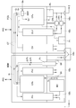
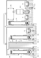
- FIG. 1 is a system diagram showing a basic configuration of a flow rate control device with a flow rate switching type flow rate monitor according to the present invention. It is a longitudinal cross-sectional schematic diagram of the flow control apparatus with a builddown type flow range switching type flow rate monitor concerning the present invention. It is a longitudinal cross-sectional schematic diagram of the pressure type flow control apparatus with a builddown type flow range switching type flow rate monitor which concerns on 2nd Embodiment of this invention. It is a schematic block diagram of the test apparatus for measuring the flow monitor characteristic of a flow control device with a build-down flow monitor. It is explanatory drawing of the pressure drop state of a builddown type
- FIG. 5 is a diagram showing the relationship between the gas flow rate SCCM and the pressure drop gradient kPa / sec when the measurable time is 1 second or less in the chambers A to E of the apparatus developed earlier.
- the pressure drop characteristics are shown when the slope of the pressure drop in each of the chambers A to E is 20 kPa / sec. It is a diagram showing the relationship between the elapsed time from the closing of the inlet side (primary side) opening / closing switching valve AV of each chamber A to E and the flow rate stability. It is a basic lineblock diagram of the conventional pressure type flow control device. It is a basic block diagram of a conventional pressure type flow control device with a flow rate monitor.
- FIG. 1 is a block diagram illustrating the basic concept of the present invention
- FIG. 2 is a system diagram showing the basic structure of a pressure type flow rate control apparatus with a flow range switching type flow rate monitor according to the present invention
- FIG. It is a longitudinal cross-sectional schematic diagram of the pressure type flow rate control apparatus with a flow range switching type flow rate monitor concerning.
- the apparatus according to the present invention is characterized in that the flow rate control with a large flow rate gas monitor and the flow rate control with a small flow rate gas monitor can be appropriately switched, and the flow rate monitor according to the present invention.
- the pressure-type flow rate control device includes a build-down unit BDM, a pressure-type flow rate control unit FCS, and a signal transmission circuit (digital communication circuit) CT that connects the two.
- 1 is a gas inlet
- 2 is a gas outlet
- PV 1 is an inlet side switching valve
- PV 2 is an outlet side switching valve
- BC is a build-down capacity
- P 3 is a pressure sensor
- ⁇ P 1 is the pressure detection value for the large flow rate monitor
- ⁇ P 2 is the pressure detection value for the small flow rate monitor
- Q 1 is the monitor flow rate detection value for the large flow rate gas
- Q 2 is the monitor flow rate for the small flow rate gas.
- the detected value, CPb is a monitor flow rate calculation control unit
- VB 1 is a monitor inlet side block
- VB 2 is a monitor outlet side block.
- CV is a control valve
- CPa is a flow rate calculation control unit
- OR 1 is a small diameter orifice
- OR 2 is a large diameter orifice
- P 1 is a first pressure sensor
- P 2 is a second pressure.
- a sensor VB 3 is a flow control unit inlet side block
- VB 4 is a flow control unit outlet side block
- VB 5 is a connection block
- SK is a gasket of the connection unit.
- the pressure type flow rate control unit FCS is provided with a set flow rate adjusting mechanism QSR, and a preset flow rate value Qs and build-down flow rates Q 1 and Q 2 inputted via the signal transmission circuit CT and a comparator.
- the set flow rate value Qs is automatically corrected to Qs ′, and the flow rate control value of the pressure type flow rate control unit FCS becomes the build-down flow rate Q 1.
- Q 2 is adjusted to match. That is, the actual flow rate is adjusted so as to match the build-down flow rates Q 1 and Q 2 .
- FIG. 3 is different from the previously developed pressure type flow rate control device with flow rate monitor of FIG. 15 and FIG. 16 in that the monitor flow rate calculation control unit CPb has a builddown flow rate Q 1 in a large flow rate range. and that outputs to be switched build-down flow rate Q 2 of the small flow rate range, and such that the pressure sensor P 3 shown in FIG. 3, and only in that provided in the connecting block VB 5, the other configurations FIG. 15 and FIG. 16 are substantially the same as the pressure type flow rate control device with a flow rate monitor. 2 and 3, the temperature detection sensor T, the filter F, and the like are omitted.
- the pressure type flow control unit FCS may be of any type, for example, one or more orifices.
- the basic configuration of the pressure type flow rate control unit FCS and the build-down type flow rate monitoring unit BDM is known per se, and detailed description thereof is omitted here.
- the present invention is configured to switch between a large flow rate gas flow rate monitor and a small flow rate range gas flow rate monitor in accordance with the gas control flow rate.
- 1 is a large flow rate Q 1 (for example, 40 to 600 SCCM)
- the pressure sensor P is maintained by opening and closing the inlet side switching valve PV 1 while keeping the outlet side switching valve PV 2 open.
- 3 is used to detect the pressure detection value ⁇ P 1
- the volume in the pipe line from the inlet side switching valve PV 1 to the control valve CV of the pressure type flow control unit FCS is set as a build-down volume
- the pressure detection value ⁇ P 1 and the pressure detection value ⁇ P 1 The monitor flow rate Q 1 in the large flow rate region is calculated using Formula 1 from the build-down volume and the like.
- the inlet side switching valve PV 1 When the gas flow rate flowing from the gas inlet 1 is a small flow rate Q 2 (for example, 2.5 to 40 (SCCM)), the inlet side switching valve PV 1 is kept open and the outlet side switching valve PV 2 is opened.
- the pressure detection value ⁇ P 2 is detected by the pressure sensor P 3 by opening and closing the valve, and the volume in the pipe line from the outlet side switching valve PV 2 to the control valve CV of the pressure type flow rate control unit FCS is defined as the build-down volume.
- a monitor flow rate Q 2 in a small flow rate region is calculated using Formula 1 from the pressure detection value ⁇ P 2 and the builddown volume.
- the monitor flow rate Q 1 (or Q 2 ) calculated by the monitor flow rate calculation control unit CPb is input to the set flow rate adjustment mechanism QSR of the flow rate control unit FCS, and the gas that has flowed out of the build-down type flow rate monitor unit BDM Flows out from the gas outlet 2 via the control valve CV, the small-diameter orifice OR 1 and / or the large-diameter orifice OR 2 , the orifice flow gas flow rate is calculated by the flow rate calculation control unit CPa, and the control valve CV open / close control and the orifice switching valve
- the opening / closing control of the OLV, the set flow rate adjustment mechanism QSR of the flow rate calculation control unit CPa compares the monitor flow rate Q 1 (or Q 2 ) from the build-down flow rate monitor unit BDM with the orifice flow rate, When the difference exceeds a predetermined set value, the control flow rate of the flow rate control unit FCS is set to match the monitor flow rate Q. That person an amount Qs is adjusted
- the output of the monitor flow rate is at least once per second, and the temperature detection sensor T (not shown) is a thermostat type thermometer inserted into the monitor block VB 1 or VB 1 . Further, the build-down capacity for the large flow rate region is formed by the volume in the chamber and the volume in the pipe line, and the capacity for the small flow rate region is formed only by the volume in the pipe line.
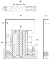
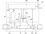
- FIG. 4A and 4B show a second embodiment of the present invention, in which FIG. 4A is a schematic longitudinal sectional view, FIG. 4B is a plan view, and FIG. 4C is a right side view.
- the pressure type flow rate control device with a flow rate range switching type flow rate monitor according to the second embodiment has four small-diameter chambers CH 1 , CH 2 , CH 3 in which build-down capacitors BC are arranged in parallel in a vertical orientation. , CH 4, and the structure of each small-diameter chamber is the same as that of the build-down capacity BC of the first embodiment, and the gap between the outer cylinder and the inner cylinder is a gas flow path. It has become.
- the four small-diameter chambers CH 1 to CH 4 are connected in a state where the gas flow passages between the inner and outer cylinders are connected in series, and the build-down capacity BC having a small inner volume V is provided. Is formed.
- the flow rate control device with a flow rate switching type flow rate monitor has a thickness L set to about 10 to 13 mm.
- the pressure sensor P 3 provided on the downstream side of the valve PV 2 is also a small one having an outer diameter of about 10 to 13 mm.
- the present invention can be widely applied not only to gas supply equipment for semiconductor manufacturing equipment but also to gas supply equipment for chemical manufacturing equipment as long as it is a pressure type flow rate control device using an orifice or a critical nozzle.
- FCS Flow controller (pressure flow controller) AV Primary open / close switching valve (upstream valve) BC Build-down capacity V Build-down volume RG Pressure regulator N 2 N 2 supply source T Temperature sensor (resistance temperature detector) P 1 , P 2 Pressure sensor P 3 Pressure sensor ⁇ P 1 , ⁇ P 2 Pressure detection value CV Control valve OR Orifice OR 1 Small bore orifice OR 2 Large bore orifice OIP External I / O circuit OLV Orifice switching valve VB 1 Monitor inlet side block VB 2 Monitor outlet side block VB 3 Flow rate control part inlet side block VB 4 Flow rate control part outlet side block VB 5 Connection part gasket CT Signal transmission circuit (digital communication circuit) CP calculation control unit CPa flow rate calculation control unit CPb monitor flow rate calculation control unit E 1 power source for flow rate control device E 2 power source for calculation control unit E 3 power source for solenoid valve ECV electric drive unit NR data logger S signal generator PC calculation display unit PV 1 Inlet side switching valve (Inlet side),
Landscapes
- Physics & Mathematics (AREA)
- General Physics & Mathematics (AREA)
- Fluid Mechanics (AREA)
- Engineering & Computer Science (AREA)
- General Engineering & Computer Science (AREA)
- Mechanical Engineering (AREA)
- Automation & Control Theory (AREA)
- Flow Control (AREA)
- Measuring Volume Flow (AREA)
Abstract
Description
尚、圧力式流量制御装置FCSそのものは公知であるため、ここではその詳細な説明を省略する(特開2003-195948号等)。
即ち、演算制御部28aへは入出力回路28bから流量設定信号Fsが入力され、質量流量制御装置20に流れる流体の流量Fが流量設定信号Fsとなるように調整される。より具体的には、演算制御部28aが第2圧力センサ27bの出力(圧力信号Spb)を用いて開閉制御弁24の開閉をフィードバック制御することにより、音速ノズル26を流れる流体の流量Fを制御すると共に、このときの熱式流量センサ25の出力(流量信号Sf)を用いて、実際に流れている流量Fの測定を行い、質量流量制御装置20の動作を確認する。
図5は、ビルドダウン式流量モニタ付圧力式流量制御装置の流量モニタ特性を測定するための試験装置の概要構成図であり、本発明者等は当該試験装置を用いて、圧力式流量制御装置FCSと一次側開閉切換弁(上流側弁)AV間の圧力降下の傾きから流量算出を行う、ビルドダウン流量測定に関する基礎的試験を行った。
また、ビルドダウン用チャンバを用いた場合には、一次側開閉切換弁(上流側弁)AVの出口とコントロール弁CVの入口間の流路内径を1.8mmとし、且つビルドダウン容量BCの内容積Vを1.58~15.31ccに選定している。
そこで、本発明者等は、ビルドダウン式による流量測定に於いて、1秒間に少なくとも1回以上の流量出力を得てリアルタイムに近い流量モニタを可能とするために、前記圧力差ΔP及びビルドダウン容量の内容積Vをより小さくしてガス再充填に必要な時間(圧力回復時間(a))を短くすることを着想し、また、当該着想に基づいて、ビルドダウン容量BCの内容積V及び流量測定時の圧力差ΔPの減少によってリアルタイム性の確保が可能か否かを検討すると共に、流量モニタ精度やその再現性等について各種の試験を行った。
更に、圧力下降範囲ΔP及びビルドダウン容量BCの内容積Vの減少による圧力回復時間(a)の短縮化は、圧力降下時間(流量出力可能時間(b))の短縮化を招くことになるため、測定流量とビルドダウン容量BCの内容積Vと圧力降下時間(b)の関係が、特に重要となることが判明した。

即ち、ビルドダウン容量BCの内容積Vを1.78cc及び9.91ccとし、圧力下降範囲ΔPを20kPa abs、一次側開閉切換弁(上流側弁)AVの閉からの流量安定までの時間を1秒として、0.25sec毎に流量を算出し、制御流量に対する算出流量の誤差を検討した。
また、ビルドダウン容量BCの内容積V=9.91ccの場合には、流量100~200SCCMの時に約1秒以内の間隔で流量出力が可能であることが判る。

尚、図15に於いて、PV1は入口側切換弁、PV2は出口側切換弁、BCはビルドダウン容量、P3は圧力センサ、CPbはモニタ流量演算制御部、VB1はモニタ入口側ブロック、VB2はモニタ出口側ブロックである。
また、図15に於いて、CVはコントロール弁、CPaは流量演算制御部、OR1は小径オリフィス、OR2は大径オリフィス、P1は第1圧力センサ、P2は第2圧力センサ、VB3は流量制御部入口側ブロック、VB4は流量制御部出口側ブロック、VB5は連結用ブロック、SKは連結部のガスケットである。
尚、図15においては、温度検出センサT, フィルタF等は省略されており、また、圧力式流量制御部FCSは如何なる形式のもの、例えばオリフィスが1基のものであっても良いことは勿論である。また、圧力式流量制御部FCSやビルドダウン式流量モニタ部BDMの基本構成そのものは公知であるため、ここではその詳細な説明を省略する。
また、ビルドダウン式流量モニタ部BDMから流出したガスは、コントロール弁CV、小径オリフィスOR 1及び又は大径オリフィスOR2を通り、ガス出口2から流出する。その間に、前記流量演算制御部CPaがオリフィス流通ガス流量を演算すると共に、コントロール弁CVの開閉制御やオリフィス切換弁OLVの開閉制御をする。
更に、前記流量演算制御部CPaの設定流量調整機構QSRでは、ビルドダウン式流量モニタ部BDMからのモニタ流量Qとオリフィス流通流量(即ち、流量演算制御部CPaでの制御流量)とが比較され、両者の差異が予め定めた設定値を超えると、圧力式流量制御部FCSの制御流量を前記モニタ流量Qに合致させるよう設定流量Qsの方を調整し、これをQs’に自動修正する。
尚、図16の装置に於いては、圧力チャンバCHの容積を自由に選定できると共に、ガス流通路L1、L2、L4等を全て同一の細径(例えば1.8mmΦ)に揃えることができ、ビルドダウン容量BCの内容積 を正確且つ容易に所定の容積値に設定することができる。
尚、図5の試験装置を用いた調査に於いて、流量センサTはチャンバCHの外表面に貼付け固定した。また、チャンバCH以外のガス流路L3、L5の容積は0.226ccである。

その結果、モニタ流量値(オリフィスを流通する実流量値)と、圧力式流量制御部FCSの設定流量値(制御流量値)とが大きく異なった状態が長期に亘って継続されるようなことが皆無となり、半導体製品の品質向上等の点で多くの効用が得られる。
特に、制御流量が大幅に変化した場合に、圧力降下値(圧力差)ΔPを略20~30kPa absとすると共に圧力降下時間Δtを0.5~0.8secとし、少なくとも1秒間当りに1回以上の割合でモニタ流量を高精度で演算して出力するためには、ビルドダウン容量BCの内容積Vを迅速且つ正確に適宜の値に調整する必要がある。その結果、ビルドダウン容量の調整機構が著しく複雑化し、流量モニタ付圧力式流量制御の大型化や製造コストの高騰を来たすと云う問題がある。
また、開閉切換弁で区切られた内容積を持つ流路を複数配置することとしたものである。
図1は本発明の基本概念を示すブロック説明する構成図であり、図2は本発明に係る流量レンジ切換型流量モニタ付圧力式流量制御装置の基本構成を示す系統図、図3は本発明に係る流量レンジ切換型流量モニタ付圧力式流量制御装置の縦断面概要図である。
本発明に係る装置は、大流量域ガスのモニタ付流量制御と小流量域ガスのモニタ付流量制御を適宜に切換え可能な構成としたことを特徴とするものであり、本発明に係る流量モニタ付圧力式流量制御装置は、ビルドダウン部BDMと圧力式流量制御部FCSと両者間を連結する信号伝送回路(デジタル通信回路)CTとから構成されている。
尚、図1乃至図3に於いて、1はガス入口、2はガス出口、PV1は入口側切換弁、PV2は出口側切換弁、BCはビルドダウン容量、P3は圧力センサ、ΔP1は大流量域モニタの場合の圧力検出値、ΔP2は小流量域モニタの場合の圧力検出値、Q1は大流量域ガスのモニタ流量検出値、Q2は小流量域ガスのモニタ流量検出値、CPbはモニタ流量演算制御部、VB1はモニタ入口側ブロック、VB2はモニタ出口側ブロックである。
また、図2及び図3では、温度検出センサTや フィルタF等は省略されている。更に、圧力式流量制御部FCSは如何なる形式のもの、例えばオリフィスが1基或いは3基以上のものであっても良いことは勿論である。尚、圧力式流量制御部FCSやビルドダウン式流量モニタ部BDMの基本構成そのものは公知であるため、ここではその詳細な説明を省略する。

当該第2実施例に係る流量レンジ切換型流量モニタ付圧力式流量制御装置は、ビルドダウン容量BCが、縦向き姿勢で並列状に配置した4本の細径チャンバCH1,CH2,CH3,CH4から構成されており、また、各細径チャンバの構造は第1実施形態のビルドダウン容量BCの場合と同一であり、外筒と内筒との間の隙間が、ガスの流通路となっている。
尚、第2実施形態に係る装置そのものの構造や機能は、第1実施形態の場合と同一であるため、ここではその詳細な説明を省略する。
FCS 流量制御部(圧力式流量制御装置)
AV 一次側開閉切換弁(上流側弁)
BC ビルドダウン容量
V ビルドダウン容積
RG 圧力調整器
N2 N2供給源
T 温度センサ(測温抵抗体)
P1、P2 圧力センサ
P3 圧力センサ
ΔP1、ΔP2 圧力検出値
CV コントロール弁
OR オリフィス
OR1 小口径オリフィス
OR2 大口径オリフィス
OIP 外部入出力回路
OLV オリフィス切換弁
VB1 モニタ入口側ブロック
VB2 モニタ出口側ブロック
VB3 流量制御部入口側ブロック
VB4 流量制御部出口側ブロック
VB5 連結部ガスケット
CT 信号伝送回路(ディジタル通信回路)
CP 演算制御部
CPa 流量演算制御部
CPb モニタ流量演算制御部
E1 流量制御装置用電源
E2 演算制御部用電源
E3 電磁弁用電源
ECV 電気駆動部
NR データロガ
S 信号発生器
PC 演算表示部
PV1 入口側切換弁(入口側ピエゾ切換弁)
PV2 出口側切換弁(出口側ピエゾ切換弁)
L1 入口側切換弁のガス入口側通路
L2 入口側切換弁のガス出口側通路
L3 出口側切換弁のガス入口側通路
L4 出口側切換弁のガス出口側通路
Cu 銅棒片
Q1、Q2 モニタ流量(ビルドダウン流量)
CH チャンバ
CH1~CH4 細径チャンバ
CHa 外筒
CHb 内筒
L 装置の厚み寸法
QSR 流量設定値調整機構
QS 設定流量
QS‘ 調整流量
1 ガス入口
2 ガス出口
CH1~CH4 細径チャンバ
Claims (16)
- 流路上に配置された入口側開閉切替弁と、該入口側開閉切替弁の下流に配置された出口側開閉切替弁と、該出口側開閉切替弁の下流に配置されたコントロール弁とを備え、前記各弁同士は内容積をもつ流路で連結され、前記コントロール弁より上流に圧力センサを配置した流量計であって、
前記入口側開閉切替弁の出口側から前記コントロール弁の入口側までの流路内容積をビルドダウン容積として流量演算する様にした大流量用測定部と、前記出口側切替弁の出口側から前記コントロール弁の入口側までの流路内容積をビルドダウン容積として流量を演算する様にした小流量用測定部とを備えることを特徴とする流量計。 - 前記コントロール弁を、流量制御部の内部のコントロール弁とした請求項1に記載の流量計。
- 開閉切換弁で区切られた内容積を持つ流路を複数配置することとした請求項1に記載の流量計。
- 上流側に設けたビルドダウン式流量モニタ部と、該ビルドダウン式流量モニタ部の下流側に設けた流量制御部とを備える流量制御装置であって、
前記ビルドダウン式流量モニタ部は、入口側開閉切換弁と、前記入口側開閉切換弁の下流側に設けたビルドダウン容量と、ビルドダウン容量の下流側に設けた出口側開閉切換弁と、前記該ビルドダウン容量の下流側のガス通路に設けた温度センサと、前記ビルドダウン容量の下流側に設けた出口側開閉切換弁と、該出口側開閉切換弁の下流側に設けた圧力センサと、前記温度センサ及び前記圧力センサの検出値が入力されるモニタ流量演算制御部とを備え、該モニタ流量演算制御部により、前記入口側開閉切換弁の出口側と前記流量制御部のコントロール弁との間のガス通路内容積をビルドダウン容積として大流量のモニタ流量を演算すると共に、前記出口側開閉切換弁の出口側と前記流量制御部のコントロール弁との間のガス通路内容積をビルドダウン容積として小流量のモニタ流量を演算する構成とされていることを特徴とする流量制御装置。 - 信号伝送回路により前記ビルドダウン式流量モニタ部と前記流量制御部とを連結し、前記ビルドダウン式流量モニタ部のモニタ流量を前記流量制御部へ伝送すると共に、該流量制御部に、前記ビルドダウン式流量モニタ部からのモニタ流量により該流量制御部の設定流量を調整する流量設定値調整機構を設ける構成した請求項1に記載の流量制御装置。
- 上流側に設けたビルドダウン式流量モニタ部と、該ビルドダウン式流量モニタ部の下流側に設けた流量制御部と、前記ビルドダウン式流量モニタ部と前記流量制御部とを連結し、前記ビルドダウン式流量モニタ部のモニタ流量を前記流量制御部へ伝送する信号伝送回路と、前記流量制御部に設けられ、前記ビルドダウン式流量モニタ部からのモニタ流量により前記流量制御部の設定流量を調整する流量設定値調整機構とを備える流量制御装置であって、前記ビルドダウン式流量モニタ部が、ガス供給源からのガスの流通を開閉する入口側開閉切換弁と、該入口側開閉切換弁の出口側に接続した所定の内容量を有するビルドダウン容量と、該ビルドダウン容量の出口側に接続した出口側開閉切換弁と、該出口側開閉切換弁の下流側通路を流通するガスの圧力を検出する圧力センサと、流通するガスの温度を検出する温度センサと、大流量の際には、前記出口側開閉切換弁を開放状態に保持すると共に、前記入口側開閉切換弁の出口側と前記流量制御部のコントロール弁との間のガス通路内容積をビルドダウン容積とし、前記入口側開閉切換弁を開閉作動させると共に該入口側開閉切換弁の開放により前記ビルドダウン容積内のガス圧力を設定上限圧力値にしたあと前記入口側開閉切換弁を閉鎖し、所定時間経過後にガス圧力を設定下限圧力値まで下降させることによりビルドダウン式により大流量のモニタ流量を演算及び出力し、また、小流量の際には、前記入口側開閉切換弁を開放状態に保持すると共に、前記出口側開閉切換弁の出口側と前記流量制御部のコントロール弁との間のガス通路内容積をビルドダウン容積とし、前記出口側開閉切換弁を開閉作動させると共に該出口側開閉切換弁の開放によりビルドダウン容積内のガス圧力を設定上限圧力値にしたあと該出口側開閉切換弁を閉鎖し、所定時間経過後にガス圧力を設定下限圧力値まで下降させることにより小流量のモニタ流量を演算及び出力するモニタ流量演算制御部とを備え、大流量及び小流量の前記各モニタ流量を、下記式により演算する構成とした流量制御装置。

- 前記流量設定値調整機構が、モニタ流量と設定流量との比較器を備え、モニタ流量と設定流量との差異が設定値を超えると、設定流量をモニタ流量に自動修正する構成の流量設定値調整機構である、請求項6に記載の流量制御装置。
- 前記流量制御部が、コントロール弁と、オリフィス又は臨界ノズルと、前記オリフィス又は臨界ノズルの上流側の圧力計、流量演算制御装置とを備える、耐圧力変動性を備えた圧力式流量制御装置である、請求項6に記載の流量制御装置。
- 前記流量制御部が、コントロール弁と、オリフィス又は臨界ノズルと、前記オリフィス又は臨界ノズルの上流側の圧力計と、前記オリフィス又は臨界ノズルの下流側の圧力計と、流量演算制御装置とを備える、耐圧力変動性を備えた圧力式流量制御装置である、請求項6に記載の流量制御装置。
- ビルドダウン容積を0.5~20ccとすると共に、設定上限圧力値を400~100kPa abs及び設定下限圧力値を350kPa abs~50kPa absに、また、所定時間を0.5~5秒以内とするようにした請求項6に記載の流量制御装置。
- 前記入口側開閉切換の出口側と前記流量制御部のコントロール弁との間のガス通路内容積を13~15ccとし、大流量のモニタ流量域を40~600SCCMとすると共に、小流量のモニタ流量域を1~50SCCMとするようにした請求項6に記載の流量制御装置。
- 前記入口側開閉切換弁をピエゾ駆動式メタルダイヤフラム弁又は電磁直動型電動弁とすると共に、弁の高速開閉により前記入口側開閉切換弁の開による設定下限圧力値から設定上限圧力値へのガス圧力の回復時間を、該入口側開閉切換弁の閉による設定上限圧力値から設定下限圧力値までのガス圧力下降時間よりも短くするようにした請求項6に記載の流量制御装置。
- 前記流量制御部の流量演算制御装置と前記ビルドダウン式流量モニタ部のモニタ流量演算制御装置とを一体に形成する構成とした請求項8に記載の流量制御装置。
- 前記流量制御部の流量演算制御装置と前記ビルドダウン式流量モニタ部のモニタ流量演算制御装置とを一体に形成する構成とした請求項9に記載の流量制御装置。
- 前記ビルドダウン容量をチャンバとすると共に、当該チャンバを内筒と外筒を同心状に配設固定した構造とし、当該チャンバを形成する内・外筒間の間隙をガス流通路とする構成とした請求項6に記載の流量制御装置。
- 前記ビルドダウン容量を、並列状に配置した複数本のチャンバとすると共に、当該チャンバを内筒と外筒を同心状に配設固定した構造とし、各チャンバの内・外筒間の間隙をガス流通路として各チャンバの前記ガス流通路を直列状に接続する構成とした請求項6に記載の流量制御装置。
Priority Applications (4)
| Application Number | Priority Date | Filing Date | Title |
|---|---|---|---|
| US15/028,127 US10073469B2 (en) | 2013-10-28 | 2014-10-21 | Flow meter and flow control device provided therewith |
| CN201480049538.XA CN105659178B (zh) | 2013-10-28 | 2014-10-21 | 流量计及具备该流量计的流量控制装置 |
| KR1020167006626A KR101843378B1 (ko) | 2013-10-28 | 2014-10-21 | 유량계 및 그것을 구비한 유량 제어 장치 |
| KR1020187000288A KR101930304B1 (ko) | 2013-10-28 | 2014-10-21 | 유량계 |
Applications Claiming Priority (2)
| Application Number | Priority Date | Filing Date | Title |
|---|---|---|---|
| JP2013223018A JP5797246B2 (ja) | 2013-10-28 | 2013-10-28 | 流量計及びそれを備えた流量制御装置 |
| JP2013-223018 | 2013-10-28 |
Publications (1)
| Publication Number | Publication Date |
|---|---|
| WO2015064050A1 true WO2015064050A1 (ja) | 2015-05-07 |
Family
ID=53003682
Family Applications (1)
| Application Number | Title | Priority Date | Filing Date |
|---|---|---|---|
| PCT/JP2014/005322 WO2015064050A1 (ja) | 2013-10-28 | 2014-10-21 | 流量計及びそれを備えた流量制御装置 |
Country Status (6)
| Country | Link |
|---|---|
| US (1) | US10073469B2 (ja) |
| JP (1) | JP5797246B2 (ja) |
| KR (2) | KR101843378B1 (ja) |
| CN (1) | CN105659178B (ja) |
| TW (1) | TWI524054B (ja) |
| WO (1) | WO2015064050A1 (ja) |
Families Citing this family (21)
| Publication number | Priority date | Publication date | Assignee | Title |
|---|---|---|---|---|
| JP6326073B2 (ja) * | 2016-01-19 | 2018-05-16 | 矢崎エナジーシステム株式会社 | ガスメータ |
| WO2017150331A1 (ja) * | 2016-02-29 | 2017-09-08 | 株式会社フジキン | 流量制御装置 |
| US10928813B2 (en) * | 2016-03-29 | 2021-02-23 | Fujikin Incorporated | Pressure-type flow rate control device and flow rate self-diagnosis method using critical expansion condition |
| US10684159B2 (en) * | 2016-06-27 | 2020-06-16 | Applied Materials, Inc. | Methods, systems, and apparatus for mass flow verification based on choked flow |
| CN109891353A (zh) * | 2016-09-19 | 2019-06-14 | 流体设备系统有限公司 | 用于流量测量的可变限制 |
| KR102208101B1 (ko) * | 2016-10-14 | 2021-01-27 | 가부시키가이샤 후지킨 | 유체 제어 장치 |
| KR101910615B1 (ko) | 2017-04-03 | 2018-10-24 | 주식회사 러셀 | 유량제어시스템 및 이를 이용한 공정모니터링시스템 |
| JP6913498B2 (ja) * | 2017-04-18 | 2021-08-04 | 東京エレクトロン株式会社 | 流量制御器の出力流量を求める方法及び被処理体を処理する方法 |
| CN107422754B (zh) * | 2017-09-01 | 2023-11-14 | 中国人民解放军军事科学院军事医学研究院 | 一种微量气体流速控制装置及控制方法 |
| US11079774B2 (en) | 2017-11-30 | 2021-08-03 | Fujikin Incorporated | Flow rate control device |
| US11105512B2 (en) | 2018-03-30 | 2021-08-31 | Midea Group Co., Ltd | Method and system for controlling a flow curve of an electromechanical gas valve |
| US11269362B2 (en) | 2018-04-27 | 2022-03-08 | Fujikin Incorporated | Flow rate control method and flow rate control device |
| US11216016B2 (en) * | 2018-06-26 | 2022-01-04 | Fujikin Incorporated | Flow rate control method and flow rate control device |
| KR102087253B1 (ko) * | 2018-07-20 | 2020-03-10 | 김영탁 | 액상 공정용 소재의 유량제어 시스템 및 이를 이용한 공정 모니터링 시스템 |
| SG11202100784RA (en) * | 2018-07-30 | 2021-02-25 | Fujikin Kk | Flow rate control system and flow rate measurement method |
| CN109012322A (zh) * | 2018-08-21 | 2018-12-18 | 王维春 | 一种畜牧业用消毒液配制装置 |
| RU2682540C9 (ru) * | 2018-08-22 | 2019-07-08 | Александр Александрович Калашников | Способ настройки измерительного канала расхода среды с сужающим устройством |
| KR20210139347A (ko) * | 2019-04-25 | 2021-11-22 | 가부시키가이샤 후지킨 | 유량 제어 장치 |
| TWI774227B (zh) * | 2020-02-21 | 2022-08-11 | 日商富士金股份有限公司 | 流量控制裝置、流量控制裝置的控制方法、流量控制裝置的控制程式 |
| CN111579013B (zh) * | 2020-05-26 | 2022-07-15 | 北京七星华创流量计有限公司 | 气体质量流量控制器及其流量标定方法 |
| US11262069B2 (en) | 2020-06-25 | 2022-03-01 | Midea Group Co., Ltd. | Method and system for auto-adjusting an active range of a gas cooking appliance |
Citations (7)
| Publication number | Priority date | Publication date | Assignee | Title |
|---|---|---|---|---|
| JPS534570A (en) * | 1975-12-30 | 1978-01-17 | Mitsui Shipbuilding Eng | Apparatus for measuring flow rate in wide range |
| JPH07281760A (ja) * | 1994-04-12 | 1995-10-27 | Ckd Corp | マスフローコントローラ絶対流量検定システム |
| JP2004246825A (ja) * | 2003-02-17 | 2004-09-02 | Stec Inc | マスフローコントローラ |
| JP2005056031A (ja) * | 2003-07-31 | 2005-03-03 | Fujikin Inc | チャンバへのガス供給装置及びこれを用いたチャンバの内圧制御方法 |
| JP2011510404A (ja) * | 2008-01-18 | 2011-03-31 | ピヴォタル システムズ コーポレーション | ガスの流量を決定する方法、ガス・フロー・コントローラの動作を決定する方法、ガスフローコントロールシステムの一部の容量を決定する方法、及びガス搬送システム |
| WO2013179550A1 (ja) * | 2012-05-31 | 2013-12-05 | 株式会社フジキン | ビルドダウン方式流量モニタ付流量制御装置 |
| WO2014156042A1 (ja) * | 2013-03-25 | 2014-10-02 | 株式会社フジキン | 流量モニタ付流量制御装置 |
Family Cites Families (15)
| Publication number | Priority date | Publication date | Assignee | Title |
|---|---|---|---|---|
| JP2982003B2 (ja) | 1992-07-28 | 1999-11-22 | コマツ電子金属株式会社 | 気相成長装置および気相成長装置におけるマスフローコントローラの校正方法 |
| JP3522544B2 (ja) * | 1998-08-24 | 2004-04-26 | 忠弘 大見 | 流体可変型流量制御装置 |
| JP4308356B2 (ja) | 1999-01-25 | 2009-08-05 | 株式会社堀場エステック | 圧力式流量コントローラのノズル診断機構および圧力式流量コントローラのノズル診断方法 |
| US6363958B1 (en) * | 1999-05-10 | 2002-04-02 | Parker-Hannifin Corporation | Flow control of process gas in semiconductor manufacturing |
| JP4102564B2 (ja) * | 2001-12-28 | 2008-06-18 | 忠弘 大見 | 改良型圧力式流量制御装置 |
| JP4137666B2 (ja) | 2003-02-17 | 2008-08-20 | 株式会社堀場エステック | マスフローコントローラ |
| CN100483286C (zh) * | 2004-06-21 | 2009-04-29 | 日立金属株式会社 | 流量控制装置及其调整方法 |
| WO2006014508A2 (en) * | 2004-07-07 | 2006-02-09 | Parker Hannifin Corporation | Flow control apparatus and method with internally isothermal control volume for flow verification |
| JP4856905B2 (ja) * | 2005-06-27 | 2012-01-18 | 国立大学法人東北大学 | 流量レンジ可変型流量制御装置 |
| JP4820698B2 (ja) * | 2006-07-03 | 2011-11-24 | 株式会社フジキン | 圧力式流量制御装置の絞り機構下流側バルブの作動異常検出方法 |
| US7891228B2 (en) * | 2008-11-18 | 2011-02-22 | Mks Instruments, Inc. | Dual-mode mass flow verification and mass flow delivery system and method |
| TWI435196B (zh) * | 2009-10-15 | 2014-04-21 | Pivotal Systems Corp | 氣體流量控制方法及裝置 |
| US8265888B2 (en) * | 2009-12-09 | 2012-09-11 | Pivotal Systems Corporation | Method and apparatus for enhancing in-situ gas flow measurement performance |
| JP5538119B2 (ja) * | 2010-07-30 | 2014-07-02 | 株式会社フジキン | ガス供給装置用流量制御器の校正方法及び流量計測方法 |
| CN105659177B (zh) * | 2013-10-31 | 2018-07-10 | 株式会社富士金 | 压力式流量控制装置 |
-
2013
- 2013-10-28 JP JP2013223018A patent/JP5797246B2/ja active Active
-
2014
- 2014-10-21 KR KR1020167006626A patent/KR101843378B1/ko active IP Right Grant
- 2014-10-21 CN CN201480049538.XA patent/CN105659178B/zh active Active
- 2014-10-21 WO PCT/JP2014/005322 patent/WO2015064050A1/ja active Application Filing
- 2014-10-21 KR KR1020187000288A patent/KR101930304B1/ko active IP Right Grant
- 2014-10-21 US US15/028,127 patent/US10073469B2/en active Active
- 2014-10-27 TW TW103137005A patent/TWI524054B/zh active
Patent Citations (7)
| Publication number | Priority date | Publication date | Assignee | Title |
|---|---|---|---|---|
| JPS534570A (en) * | 1975-12-30 | 1978-01-17 | Mitsui Shipbuilding Eng | Apparatus for measuring flow rate in wide range |
| JPH07281760A (ja) * | 1994-04-12 | 1995-10-27 | Ckd Corp | マスフローコントローラ絶対流量検定システム |
| JP2004246825A (ja) * | 2003-02-17 | 2004-09-02 | Stec Inc | マスフローコントローラ |
| JP2005056031A (ja) * | 2003-07-31 | 2005-03-03 | Fujikin Inc | チャンバへのガス供給装置及びこれを用いたチャンバの内圧制御方法 |
| JP2011510404A (ja) * | 2008-01-18 | 2011-03-31 | ピヴォタル システムズ コーポレーション | ガスの流量を決定する方法、ガス・フロー・コントローラの動作を決定する方法、ガスフローコントロールシステムの一部の容量を決定する方法、及びガス搬送システム |
| WO2013179550A1 (ja) * | 2012-05-31 | 2013-12-05 | 株式会社フジキン | ビルドダウン方式流量モニタ付流量制御装置 |
| WO2014156042A1 (ja) * | 2013-03-25 | 2014-10-02 | 株式会社フジキン | 流量モニタ付流量制御装置 |
Also Published As
| Publication number | Publication date |
|---|---|
| JP5797246B2 (ja) | 2015-10-21 |
| US10073469B2 (en) | 2018-09-11 |
| JP2015087110A (ja) | 2015-05-07 |
| KR101843378B1 (ko) | 2018-03-29 |
| CN105659178B (zh) | 2017-12-22 |
| CN105659178A (zh) | 2016-06-08 |
| TWI524054B (zh) | 2016-03-01 |
| TW201531668A (zh) | 2015-08-16 |
| KR101930304B1 (ko) | 2018-12-18 |
| KR20160043060A (ko) | 2016-04-20 |
| US20160239026A1 (en) | 2016-08-18 |
| KR20180004854A (ko) | 2018-01-12 |
Similar Documents
| Publication | Publication Date | Title |
|---|---|---|
| WO2015064050A1 (ja) | 流量計及びそれを備えた流量制御装置 | |
| JP5847106B2 (ja) | 流量モニタ付圧力式流量制御装置。 | |
| JP2015087110A5 (ja) | ||
| JP5768186B2 (ja) | ビルドダウン方式流量モニタ付流量制御装置及びこれを用いたモニタ付流量制御方法。 | |
| JP2020098653A (ja) | 質量流量制御装置の流量をリアルタイムで監視するシステムおよび方法 | |
| JP5727596B2 (ja) | 流量モニタ付圧力式流量制御装置の実ガスモニタ流量初期値のメモリ方法及び実ガスモニタ流量の出力確認方法 | |
| TWI470187B (zh) | Flow measurement device for flow control device for gas supply device and flow measurement method | |
| TW201433897A (zh) | 用於壓力式質流控制器之自驗證的方法及裝置 | |
| JP7244940B2 (ja) | 流量制御システム及び流量測定方法 | |
| JP7249030B2 (ja) | 流量測定装置内の容積測定方法および流量測定装置 | |
| JP2023163311A (ja) | 流量測定装置、流量測定方法および流量制御装置の校正方法 |
Legal Events
| Date | Code | Title | Description |
|---|---|---|---|
| 121 | Ep: the epo has been informed by wipo that ep was designated in this application |
Ref document number: 14858650 Country of ref document: EP Kind code of ref document: A1 |
|
| ENP | Entry into the national phase |
Ref document number: 20167006626 Country of ref document: KR Kind code of ref document: A |
|
| WWE | Wipo information: entry into national phase |
Ref document number: 15028127 Country of ref document: US |
|
| NENP | Non-entry into the national phase |
Ref country code: DE |
|
| 122 | Ep: pct application non-entry in european phase |
Ref document number: 14858650 Country of ref document: EP Kind code of ref document: A1 |