WO2014156038A1 - 輻射ヒータ装置 - Google Patents
輻射ヒータ装置 Download PDFInfo
- Publication number
- WO2014156038A1 WO2014156038A1 PCT/JP2014/001487 JP2014001487W WO2014156038A1 WO 2014156038 A1 WO2014156038 A1 WO 2014156038A1 JP 2014001487 W JP2014001487 W JP 2014001487W WO 2014156038 A1 WO2014156038 A1 WO 2014156038A1
- Authority
- WO
- WIPO (PCT)
- Prior art keywords
- heat generating
- heat
- heater device
- electrode
- electrodes
- Prior art date
- Legal status (The legal status is an assumption and is not a legal conclusion. Google has not performed a legal analysis and makes no representation as to the accuracy of the status listed.)
- Ceased
Links
Images







Classifications
-
- B—PERFORMING OPERATIONS; TRANSPORTING
- B60—VEHICLES IN GENERAL
- B60H—ARRANGEMENTS OF HEATING, COOLING, VENTILATING OR OTHER AIR-TREATING DEVICES SPECIALLY ADAPTED FOR PASSENGER OR GOODS SPACES OF VEHICLES
- B60H1/00—Heating, cooling or ventilating devices
- B60H1/22—Heating, cooling or ventilating devices the heat source being other than the propulsion plant
- B60H1/2215—Heating, cooling or ventilating devices the heat source being other than the propulsion plant the heat being derived from electric heaters
-
- B—PERFORMING OPERATIONS; TRANSPORTING
- B60—VEHICLES IN GENERAL
- B60H—ARRANGEMENTS OF HEATING, COOLING, VENTILATING OR OTHER AIR-TREATING DEVICES SPECIALLY ADAPTED FOR PASSENGER OR GOODS SPACES OF VEHICLES
- B60H1/00—Heating, cooling or ventilating devices
- B60H1/22—Heating, cooling or ventilating devices the heat source being other than the propulsion plant
- B60H1/2215—Heating, cooling or ventilating devices the heat source being other than the propulsion plant the heat being derived from electric heaters
- B60H1/2226—Electric heaters using radiation
-
- B—PERFORMING OPERATIONS; TRANSPORTING
- B60—VEHICLES IN GENERAL
- B60H—ARRANGEMENTS OF HEATING, COOLING, VENTILATING OR OTHER AIR-TREATING DEVICES SPECIALLY ADAPTED FOR PASSENGER OR GOODS SPACES OF VEHICLES
- B60H1/00—Heating, cooling or ventilating devices
- B60H1/22—Heating, cooling or ventilating devices the heat source being other than the propulsion plant
- B60H1/2215—Heating, cooling or ventilating devices the heat source being other than the propulsion plant the heat being derived from electric heaters
- B60H1/2227—Electric heaters incorporated in vehicle trim components, e.g. panels or linings
-
- F—MECHANICAL ENGINEERING; LIGHTING; HEATING; WEAPONS; BLASTING
- F24—HEATING; RANGES; VENTILATING
- F24C—DOMESTIC STOVES OR RANGES ; DETAILS OF DOMESTIC STOVES OR RANGES, OF GENERAL APPLICATION
- F24C7/00—Stoves or ranges heated by electric energy
- F24C7/04—Stoves or ranges heated by electric energy with heat radiated directly from the heating element
- F24C7/043—Stoves
-
- F—MECHANICAL ENGINEERING; LIGHTING; HEATING; WEAPONS; BLASTING
- F24—HEATING; RANGES; VENTILATING
- F24D—DOMESTIC- OR SPACE-HEATING SYSTEMS, e.g. CENTRAL HEATING SYSTEMS; DOMESTIC HOT-WATER SUPPLY SYSTEMS; ELEMENTS OR COMPONENTS THEREFOR
- F24D19/00—Details
- F24D19/02—Arrangement of mountings or supports for radiators
-
- F—MECHANICAL ENGINEERING; LIGHTING; HEATING; WEAPONS; BLASTING
- F28—HEAT EXCHANGE IN GENERAL
- F28F—DETAILS OF HEAT-EXCHANGE AND HEAT-TRANSFER APPARATUS, OF GENERAL APPLICATION
- F28F7/00—Elements not covered by group F28F1/00, F28F3/00 or F28F5/00
-
- H—ELECTRICITY
- H05—ELECTRIC TECHNIQUES NOT OTHERWISE PROVIDED FOR
- H05B—ELECTRIC HEATING; ELECTRIC LIGHT SOURCES NOT OTHERWISE PROVIDED FOR; CIRCUIT ARRANGEMENTS FOR ELECTRIC LIGHT SOURCES, IN GENERAL
- H05B3/00—Ohmic-resistance heating
- H05B3/20—Heating elements having extended surface area substantially in a two-dimensional [2D] plane, e.g. plate-heater
-
- H—ELECTRICITY
- H05—ELECTRIC TECHNIQUES NOT OTHERWISE PROVIDED FOR
- H05B—ELECTRIC HEATING; ELECTRIC LIGHT SOURCES NOT OTHERWISE PROVIDED FOR; CIRCUIT ARRANGEMENTS FOR ELECTRIC LIGHT SOURCES, IN GENERAL
- H05B2203/00—Aspects relating to Ohmic resistive heating covered by group H05B3/00
- H05B2203/032—Heaters specially adapted for heating by radiation heating
Definitions
- the disclosed invention relates to a radiation heater device that warms an object by radiation.
- Patent Document 1 and Patent Document 2 disclose radiation heater devices. This device is provided so as to face an occupant in a vehicle interior.
- the above device is effective as a device for giving a sense of heat to the passenger to assist the vehicle heating device.
- further improvements are required for the radiation heater device.
- One of the inventions is a substrate part (2) formed to provide a surface by an electrically insulating material, and a pair of electrodes (4, 41, 42) supported by the substrate part so as to extend along the surface.
- a pair of electrodes (4, 41, 42) supported by the substrate part so as to extend along the surface.
- R radiant heat
- it is made of a material having a higher electrical specific resistance than the electrode, and is supported by the substrate portion so as to extend along the surface.
- a plurality of heat generating portions (5, 205, 305) arranged in parallel therebetween.
- the heat generating part is made of a material having a higher electrical specific resistance than the electrode.
- the specific resistance of the electrode material is lower than the specific resistance of the heat generating material.
- the radiation heater apparatus 1 which concerns on 1st Embodiment is installed in the room
- the apparatus 1 constitutes a part of the heating apparatus 10 for the room.
- the device 1 is an electric heater that generates heat by being fed from a power source such as a battery or a generator mounted on a moving body.
- the device 1 is formed in a thin plate shape.
- the device 1 generates heat when electric power is supplied.
- the apparatus 1 radiates radiant heat R mainly in a direction perpendicular to the surface in order to warm an object positioned in a direction perpendicular to the surface.
- the device 1 is installed indoors so as to radiate radiant heat R to the feet of the occupant 12.
- the device 1 can be used as a device for immediately providing warmth to the occupant 12 immediately after the heating device 10 is activated.
- the device 1 is installed on a wall surface in the room.
- the apparatus 1 is installed so as to face an occupant 12 in a normal posture assumed.
- the road traveling vehicle has a steering column 13 for supporting the handle 14.
- the device 1 can be installed on the lower surface of the steering column 13.
- the apparatus 1 is installed such that its surface is exposed toward the room.
- the device 1 is substantially exposed indoors without having a cover member for preventing the occupant 12 from directly touching the surface of the device 1.
- the device 1 extends along an XY plane defined by an axis X and an axis Y.
- the apparatus 1 is formed in a substantially rectangular thin plate shape.
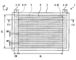
- the apparatus 1 includes a substrate unit 2, a plurality of electrodes 3 and 4, and a plurality of heat generating units 5. In the drawing, hatching is added to show the electrodes 3 and 4 embedded in the substrate part 2 and the heat generating part 5.
- FIG. 3 shows a III-III cross section of FIG.
- the device 1 has a thickness in the direction of the axis Z.
- the apparatus 1 can also be called a planar heater that radiates radiant heat R mainly in a direction perpendicular to the surface.
- the substrate part 2 is made of a resin material that provides excellent electrical insulation and withstands high temperatures.
- the substrate unit 2 provides a surface.
- the substrate part 2 is formed in a flat plate shape.
- the board part 2 is given a curved surface corresponding to the wall surface of the installation place.
- substrate part 2 has the rigidity which can maintain the shape.
- substrate part 2 can have the flexibility for deform
- the substrate part 2 can be made of a thermoplastic resin.
- the substrate unit 2 is a multilayer substrate.
- the substrate unit 2 has a front surface layer 21, a back surface layer 22, and an intermediate layer 23. These layers 21, 22, 23 are provided by a sheet of thermoplastic resin.
- the surface layer 21 faces the radiation direction of the radiant heat R. In other words, the surface layer 21 provides a surface that is disposed so as to face a part of the occupant 12 that is the object to be heated in the installed state of the device 1. The surface of the surface layer 21 is exposed toward the room.
- the back layer 22 provides the back of the device 1.
- the intermediate layer 23 is disposed between the front surface layer 21 and the back surface layer 22. On one or more of the layers 21, 22, 23, a material for forming the electrodes 3, 4 and the heat generating portion 5 is supported.
- the substrate unit 2 is a member for supporting the electrodes 3 and 4 and the heat generating unit 5.
- the material for providing the substrate part 2 provides a sufficiently lower thermal conductivity than the electrodes 3, 4 and the heat generating part 5.
- substrate part 2 provides the heat insulation part which suppresses heat conduction between the two adjacent heat-emitting parts 5.
- the plurality of electrodes 3 and 4 includes an external electrode 3 at least a part of which is exposed to the outside of the apparatus 1 and an internal electrode 4 disposed in the substrate unit 2.
- the electrode 3 includes a pair of electrodes 31 and 32 for supplying power.
- the pair of electrodes 31 and 32 provide a terminal for the device 1.
- These electrodes 3 are arranged on the outer surface of the substrate portion 2 including the outer edge portion, the front surface, and the back surface of the substrate portion 2.
- a part of the electrode 3 is embedded in the substrate portion 2 and is electrically connected to the electrode 4.
- the electrode 4 may be exposed to the outer surface of the substrate portion 2 and used as a terminal for supplying the electrode.
- the electrode 4 is embedded in the substrate part 2.
- the electrode 4 is also a bus bar portion that distributes power to a plurality of heat generating portions 5 to be described later.
- the electrode 4 extends from the electrode 3.
- the electrode 4 has a sufficiently low electric resistance value as compared with the plurality of heat generating portions 5.
- the electric resistance value of the electrode 4 is set so that heat generation in the electrode 4 can be suppressed.
- the electrode 4 distributes the current evenly to the plurality of heat generating portions 5.
- the electrode 4 has a pair of electrodes 41 and 42 for supplying electric power.
- the pair of electrodes 41 and 42 are disposed at both ends of the unit region of the substrate unit 2 so as to be separated from each other.
- the pair of electrodes 41, 42 extend along both sides of the unit region of the substrate unit 2. A region where the pair of electrodes 41 and 42 are provided and a region between them define a unit region.
- Each of the plurality of heat generating portions 5 is embedded in the substrate portion 2.
- the heat generating part 5 is disposed between the front surface layer 21 and the back surface layer 22. Therefore, the heat generating part 5 is not exposed on the surface of the substrate part 2.
- the heat generating part 5 is protected by the substrate part 2.
- the heat generating part 5 is disposed between the pair of electrodes 41 and 42.
- the heat generating part 5 extends linearly between the pair of electrodes 41 and 42.
- the heating part 5 can be called a linear heating element.
- the heat generating portion 5 extends straightly between the pair of electrodes 41 and 42.
- One end of the heat generating part 5 is electrically and mechanically connected to one electrode 41.
- the other end of the heat generating part 5 is electrically and mechanically connected to the other electrode 42.
- the heat generating part 5 is formed in a thin plate shape parallel to the surface of the substrate part 2.
- the heat generating part 5 can radiate radiant heat R by heat supplied by energization.
- the heat generating part 5 can radiate radiant heat R that makes the occupant 12, that is, a person feel warm, by being heated to a predetermined radiation temperature Tr.
- the volume of the heat generating part 5 is set so that the heat supplied from the heat generating part 5 can reach a temperature at which the heat generating part 5 can radiate the radiant heat R.
- the volume of the heat generating part 5 is set so that the temperature of the heat radiating part 3 is rapidly increased by the heat supplied from the heat generating part 5.
- the volume of the heat generating unit 5 is set to be small so that a rapid temperature drop is caused by heat radiation to an object that is in contact with the surface of the device 1.
- the thickness of the heat generating part 5 is set thin in order to maximize the area parallel to the surface and minimize the volume.
- the area of the heat generating part 5 is set to a size suitable for radiating radiant heat R.
- the area of the heat generating part 5 is set smaller than an object positioned facing the surface of the device 1, for example, a part of the occupant 12.
- the plurality of heat generating parts 5 are arranged in parallel to each other.
- the plurality of heat generating portions 5 are electrically connected in parallel between the pair of electrodes 41 and 42.
- the plurality of heat generating portions 5 are arranged so as to define a gap 6 therebetween.
- the plurality of heat generating portions 5 are arranged so as to be distributed substantially evenly with respect to the surface of the substrate portion 2.
- the plurality of heat generating portions 5 are arranged so as to be distributed with a substantially uniform density in a region between the pair of electrodes 41 and 42.
- the plurality of heat generating units 5 are distributed in the most part of the unit area of the substrate unit 2.
- the shape and dimensions that define the cross-sectional area of the electrodes 3 and 4 in the energization direction, and the materials of the electrodes 3 and 4 are selected and set so as to provide a low electrical resistance value.
- the cross-sectional areas and materials of the electrodes 3 and 4 are set so as to provide a good electric conductor in order to distribute the current evenly to the plurality of heat generating portions 5.
- the shape and dimensions that define the cross-sectional area in the energization direction of the heat generating portion 5 and the material of the heat generating portion 5 are selected and set so as to provide a high electric resistance value so as to generate radiant heat R by energization. .
- the material of the electrodes 3 and 4 and the material of the heat generating part 5 are different materials.
- the electrical specific resistance of the material of the electrodes 3 and 4 is sufficiently lower than the electrical specific resistance of the material of the heat generating part 5.
- the electrode 4 is elongated and has a longitudinal direction along the axis Y.
- the electrode 4 has a length EL along the axis Y.
- the length EL corresponds to the energization direction in the electrode 4.
- the electrode 4 has a width EW along the axis X.
- the width EW is orthogonal to the energization direction.
- the electrode 4 has a thickness ET along the axis Z. The thickness ET is smaller than the length EL and the width EW.
- the electrode 4 provides a ribbon-like electrical conductor.
- the heat generating part 5 is elongated and has a longitudinal direction along the axis X.
- the heat generating part 5 has a length HL along the axis X.
- the length HL corresponds to the energization direction in the heat generating portion 5.
- the heat generating part 5 has a width HW along the axis Y.
- the width HW is orthogonal to the energization direction.
- the heat generating part 5 has a thickness HT along the axis Z.
- the thickness HT is smaller than the length HL and the width HW. Therefore, the heat generating part 5 provides a ribbon-shaped heat generating element.
- Width HW is 300 ⁇ m.
- the width HW can be in the range of 100 ⁇ m to 3 mm.
- the width HW is desirably set smaller than 1 mm.
- the width HW is desirably set smaller than 500 ⁇ m.
- the thickness HT is 30 ⁇ m.
- the thickness HT can be in the range of 10 ⁇ m to 100 ⁇ m.
- the thickness HT is desirably set smaller than the width HW (HW> HT).
- the thickness HT is desirably set to be smaller than 1 mm.
- the thickness HT is desirably set to be smaller than 100 ⁇ m.
- the width EW is set larger than the width HW in order to suppress the electric resistance value in the electrode 4.
- the cross-sectional area of the electrode 4 orthogonal to the energizing direction is larger than the cross-sectional area of the heat generating part 5 orthogonal to the energizing direction.
- the specific resistance of the electrode 4 smaller than the specific resistance of the heating element 5 makes it possible to suppress the cross-sectional area of the electrode 4.
- the thickness ET may be set larger than the thickness HT.
- the gap 6 has a width GW.
- the length of the gap 6 is the same as the length HL of the heat generating portion 5.
- the plurality of heating portions 5 and the plurality of gaps 6 are alternately arranged over the entire length EL of the electrode 4.
- the width GW of the gap 6 can be set equal to the width HW of the heat generating portion 5.
- the several heat-emitting part 5 is arrange
- the heat generating portions 5 and the gaps 6 having fine widths HW and GW are arranged with high density. As a result, the temperature distribution on the surface of the radiation heater device 1 is suppressed.
- Such a high-density arrangement of the fine heat generating portions 5 contributes to radiating uniform radiant heat R from the surface of the radiant heater device 1.
- the radiation heater device 1 is formed in a thin plate shape. Furthermore, the electrodes 3 and 4 and the heat generating part 5 embedded in the substrate part 2 are in the form of a film extending in parallel with the surface of the substrate part 2. Such film-like electrodes 3 and 4 and the heat generating part 5 are advantageous for radiating radiant heat R over a wide area.
- the heat generating part 5 is made of a material that generates heat when energized.
- the heat generating part 5 shows an electrical resistance value along the energization direction so as to generate heat when energized.
- the heat generating part 5 can be made of a metal material.
- the heat generating part 5 can be made of a tin alloy.
- the heat generating part 5 can be made of an alloy containing copper, silver, and tin.
- the heat generating part 5 can also be made of a heating wire material such as a stainless alloy, a nickel-chromium alloy, or an aluminum alloy.
- the electrodes 3 and 4 are made of a material having a lower electrical specific resistance than the material of the heat generating portion 5.
- the electrodes 3 and 4 are made of a material that generates less heat than the heat generating portion 5 when energized.
- the electrodes 3 and 4 are made of a material having a low specific resistance so that current can be evenly distributed to the plurality of heat generating portions 5.
- the electrodes 3 and 4 can be made of a metal material.
- the electrodes 3 and 4 can be made of a tin alloy.
- the electrodes 3 and 4 can be made of an alloy containing copper, silver, and tin.
- the electrodes 3 and 4 can also be made of a good conductor material such as a copper alloy or an aluminum alloy.
- the electrode 4 and the heat generating part 5 are electrically connected.
- the electrode 4 and the heat generating part 5 are connected by sintering.
- At least one of the electrode 4 and the heat generating part 5 is provided by an alloy containing tin.
- the materials for providing the substrate part 2, the electrode 4, and the heat generating part 5 are heated under pressure.
- the electrode 4 and the heat generating part 5 are integrated by sintering.
- the electrode 4 can be provided by a copper foil
- the heat generating part 5 can be provided by a powder layer containing tin and silver.
- the powder layer can be provided by a paste layer containing tin powder, silver powder, and a binder resin.
- the powder layer is alloyed to provide a heat generating part 5 made of an alloy integrated by sintering.
- a solid phase diffusion layer is formed between the powder layer and the copper foil.
- the electrode 4 may be provided by a powder layer containing tin and silver, and the heating part 5 may be provided by a thin film of heating wire material. Further, the electrode 4 may be provided by a copper foil, the heat generating portion 5 may be provided by a thin film of heating wire material, and a powder layer containing tin and silver may be interposed between them as a joining member.
- the plurality of heat generating portions 5 form an energization path connected in parallel between the pair of electrodes 41 and 42.
- a predetermined voltage for example, 12V DC power is supplied to the electrodes 31 and 32
- the plurality of heat generating units 5 generate heat due to the current flowing through the plurality of heat generating units 5.
- the radiant heat R is provided from the surface of the device 1 as the plurality of heat generating portions 5 generate heat.
- the temperature of the several heat-emitting part 5 rises earlier than the temperature rise of the indoor air by a heating apparatus. As a result, the occupant 12 can be warmed by the radiant heat R faster than the heating effect by the heating device.
- the volume of the electrode 4 and the heat generating part 5 is set so as to reduce the heat capacity.
- the heat capacity of the heat generating part 5 is set such that the temperature of the part in contact with the object decreases in a short time after the object contacts the surface of the radiation heater device 1 on the heat generating part 5.
- the heat capacity of the heat generating part 5 is set such that when an object comes into contact with the surface of the radiant heater device 1, the surface temperature of the radiant heater device 1 at the contact portion falls below a predetermined temperature in a short time. In a desirable form, when a human finger contacts the surface of the radiant heater device 1, the heat capacity of the heat generating portion 5 is set so that the surface temperature of the contact portion falls below 60 ° C. in 0.32 seconds after the contact.
- the specifications of the radiant heater device 1, for example, the dimensions, performance, and materials of each part can be set based on a thermal model.
- the specifications of the radiant heater device 1 are set so that the required heat supply can be realized in a state where no object is in contact with the surface of the radiant heater device 1. Further, the specification of the radiant heater device 1 is set so that the surface temperature of the contact portion is lowered to a temperature that does not damage the object when the object is in contact with the surface of the radiant heater device 1.
- the specification of the radiation heater device 1 is set so as to satisfy both of the above two cases.
- the cross-sectional area CA orthogonal to the length direction of the heat generating part 5 can be set based on a heat transfer model.
- FIG. 4 shows a heat transfer model in a state where no object is in contact with the radiation heater device 1.
- this heat transfer model the flow of heat toward the surface (upper surface) of the radiant heater device 1 among the heat generated by the heat generating portion 5 is modeled.
- the amount of heat generated by the heat generating portion 5 per unit area on the surface of the radiation heater device 1 is Q0.
- Q0 is obtained based on the material of the heat generating part 5, the dimensions of the heat generating part 5, and the current flowing through the heat generating part 5.
- the heat generating part 5 has a cross-sectional area CA in a cross section orthogonal to the length direction.
- the temperature of the heat generating part 5 is T1.
- the surface temperature of the surface layer 21 is T2.
- the thermal conductivity in the heat generating part 5 is ⁇ 1 (lambda 1).
- the heat transfer coefficient between the heat generating portion 5 and the surface of the surface layer 21 is ⁇ 2 (lambda 2).
- the thickness of the surface layer 21 is t21.
- the amount of heat transfer Q1 (W / m 2 ) transmitted to the surface of the surface layer 21 can be expressed by the following equation (1).
- Heat release from the surface of the radiation heater device 1 is mainly performed by convection and radiation.
- Let h be the heat transfer coefficient by natural convection.
- the temperature of the air is T0.
- the heat dissipation amount Q2 (W / m 2 ) by convection can be expressed by the following equation (2).
- the emissivity from the surface of the radiation heater device 1 is ⁇ (epsilon), and the Stefan-Boltzmann constant is ⁇ (sigma).
- the heat release amount Q4 due to radiation can be expressed by the following equation (3).
- the surface temperature T2 is stabilized at a required temperature.
- the specification of the radiation heater device 1 is set so that the surface temperature T2 becomes the radiation temperature Tr that can supply the required radiation heat R.
- the radiation temperature Tr is a predetermined temperature of, for example, 60 ° C. or higher.
- FIG. 5 shows a heat transfer model in a state where the human second finger FG is in contact with the radiation heater device 1.
- an object contacts the surface of the radiation heater device 1
- convection and radiation are at least partially hindered.
- at least a part of the heat radiation from the surface of the radiation heater device 1 is provided by heat transfer to the contacted object.
- the thermal balance inside the radiation heater device 1 changes.
- the temperature of the heat generating part 5 is T1t.
- the surface temperature of the surface layer 21 is T2t.
- the amount of heat transfer Q1t transmitted to the surface of the surface layer 21 can be expressed by the following equation (4).
- K be the heat transfer rate of the contacting object.
- T4 be the internal temperature of the contacting object.
- the amount of heat Q4 radiated from the surface of the surface layer 21 immediately below the contacting object, in other words, the amount of heat Q4 absorbed by the contacting object can be expressed by the following equation (5).
- the surface temperature decreases from T2 to T2t.
- the temperature of the heat generating portion 5 immediately below the contact portion also decreases from T1 to T1t. Due to the temperature drop due to contact, lateral heat transfer occurs.
- the heat generating part 5 is surrounded by the substrate part 2 having a much lower heat transfer coefficient. Therefore, the amount of heat passing through the heat generating part 5 is dominant in the lateral heat transfer.
- Rh be the thermal resistance in the lateral direction of the heat generating portion 5, that is, in the length direction of the heat generating portion 5.
- T3t be the temperature of the heat generating portion 5 where the surrounding temperature is not lowered.
- the amount of heat transfer Q5 passing through the heat generating part 5 in parallel with the surface of the radiation heater device 1, that is, in the lateral direction can be expressed by the following equation (6).
- the length of the heat generating part 5 is HL.
- the thermal resistance Rh (K / W) in the length direction of the heat generating part 5 can be expressed by the following equation (7).
- the surface temperature T2 decreases due to the amount of heat that the object carries away.
- the surface temperature T2t is stabilized at a temperature lower than the radiation temperature Tr.
- the specification of the radiant heater device 1 is set so that the surface temperature T2t becomes the suppression temperature Tp for protecting the object in contact.
- the material that defines the thermal resistance Rh and the cross-sectional area CA can be used as conditions that can be changed.
- the material of the heat generating part 5 and the cross-sectional area CA are set so that the surface temperature T2t becomes the suppression temperature Tp.
- the suppression temperature Tp is a predetermined temperature of 50 ° C. or less, for example.
- the contacting object can carry away a predetermined amount of heat. For example, when a part of a person, such as a finger, touches, heat is carried away by the bloodstream.
- the amount of heat that an object in contact can carry away is QH.
- the suppression temperature Tp can be 40 degrees C or less.
- the horizontal axis indicates the thermal resistance Rh (K / W) in the length direction of the heat generating portion 5.
- the vertical axis represents the surface temperature T2 of the radiation heater device 1.
- the vertical axis is also the surface temperature T2t when the object is in contact.
- the surface temperature T2t is suppressed to be lower than the predetermined temperatures T21 and T22 by forming the heat generating portion 5 so that the thermal resistance Rh exceeds the predetermined value.
- the thermal resistance Rh is the length L (m) of the heat generating portion, the thermal conductivity ⁇ 1 (W / m ⁇ K) in the length direction of the heat generating portion, and the cross-sectional area CA ( m 2 ) and can be expressed by the following formula (8).
- the thermal resistance Rh in order to fall below the predetermined temperature T21, can be set to exceed 700 (K / W). In order to fall below the predetermined temperature T21, the thermal resistance Rh is desirably set to exceed 1000 (K / W). The thermal resistance Rh can be set to be higher than, for example, 7000 (K / W).
- Predetermined temperatures T21 and T22 can be set so that no traces caused by heat remain on the contacted object. In addition, when it is assumed that a part of the human is in contact, the predetermined temperatures T21 and T22 are set so that the heat perceived by the human can be tolerated or the heat perceived by the human can be withstood. can do.
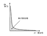
- the horizontal axis represents the heat transfer coefficient ⁇ 1 (W / m ⁇ K) in the length direction of the heat generating portion 5.
- the vertical axis represents the cross-sectional area CA (m 2 ) orthogonal to the length direction of the heat generating part.
- a region where the thermal resistance Rh exceeds 700 (K / W) (Rh> 700 (K / W)) is indicated by hatching, and the boundary is indicated by a solid line.
- the cross-sectional area CA of the heat generating part 5 is set so as to realize the target thermal resistance Rh according to the heat transfer coefficient ⁇ of the heat generating part 5, that is, the material.
- the cross-sectional area CA can be set in the vicinity of 300 ⁇ m ⁇ 30 ⁇ m.
- the cross-sectional area CA can be set to be less than 2500 ⁇ m 2 .
- the diameter can be set to be less than 500 ⁇ m.
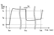
- FIG. 8 shows an example of the operation of the first embodiment.
- energization of the radiation heater device 1 is started.
- the surface temperature T2 rises rapidly from the room temperature T0 immediately after the start of energization.
- the surface temperature T2 quickly reaches the radiation temperature Tr that can radiate the radiant heat R. Thereby, a quick start-up characteristic is obtained.
- the temperature rise after the start of energization is much faster than the air temperature rise by the heating device. For this reason, the radiant heater device 1 is effective as an immediate effect heating device.
- the object comes into contact with the surface of the radiation heater device 1.
- the contacted object takes heat from the radiation heater device 1.
- the radiation heater device 1 is formed with the substrate part 2, the electrodes 3, 4 and the heat generating part 5 so as to suppress the heat capacity in the unit area.
- the radiant heater device 1 is formed so as to suppress lateral heat transfer along the surface thereof.
- the radiation heater device 1 is given a high thermal resistance Rh in the lateral direction.
- the heat generation part 5 that is dominant with respect to the thermal resistance in the lateral direction of the radiation heater device 1 is given a high thermal resistance Rh. For this reason, the inflow of the heat from the circumference
- the surface temperature T2 of the radiation heater device 1 rapidly decreases. At this time, the surface temperature T2 rapidly decreases from the radiation temperature Tr to the suppression temperature Tp. The period Td during which the surface temperature T2 exceeds the suppression temperature Tp after the object contacts is short. For this reason, even if a human contacts, the amount of heat received per unit time is suppressed to a level acceptable to humans.
- the surface temperature T2 does not rise rapidly while the object is in contact. While the object is in contact, the surface temperature T2 is maintained at a low temperature. The surface temperature T2 gradually increases. For this reason, even if a human makes contact, the human can release the contacted part while the amount of heat received per unit time is at an acceptable level.
- the radiant heater device 1 has the substrate portion 2 formed so as to provide a surface with an electrically insulating material.
- the radiation heater device 1 includes an electrode 4 supported on a substrate portion so as to extend along the surface, and a plurality of heat generating portions 5.
- the pair of electrodes 4, 41, 42 is supported by the substrate portion 2 so as to extend along the surface.
- the plurality of heat generating portions 5 are made of a material having a higher electrical specific resistance than the electrode 4 in order to emit radiant heat R by generating heat when energized.
- the plurality of heat generating portions 5 are supported by the substrate portion 2 so as to extend along the surface, and are arranged in parallel between the pair of electrodes 4.
- the plurality of heat generating portions 5 are arranged in parallel between the electrodes 4. For this reason, large heat generation can be obtained by parallel energization to the plurality of heat generating portions 5.
- the heat generating part 5 is made of a material having a higher electrical specific resistance than the electrode 4. Conversely, the specific resistance of the material of the electrode 4 is lower than the specific resistance of the material of the heat generating part 5.
- a large current flows through the electrode 4 by connecting the plurality of heat generating portions 5 in parallel, but heat generation of the electrode 4 is suppressed.
- variations in current distribution to the plurality of heat generating portions 5 are suppressed.
- the electrode 4 is formed of a material having a lower electrical specific resistance than the heat generating portion 5. According to this configuration, the area occupied by the film-like electrode 4 in the XY plane is suppressed.
- the substrate unit 2 has a front surface layer 21 and a back surface layer 22.
- the electrodes 3 and 4 and the heat generating part 5 are disposed between the front surface layer 21 and the back surface layer 22.
- the substrate portion 2 has a flat plate shape, and the electrodes 3 and 4 and the heat generating portion 5 have a film shape extending along the surface.
- the thermal capacity of both the electrode 4 and the heat generating part 5 is suppressed. As a result, the temperature of the heat generating portion 5 rises quickly in response to energization. Moreover, when an object contacts, the temperature of the heat generating part 5 will fall rapidly. Furthermore, the heat generating part 5 is embedded in the substrate part 5 having a low thermal conductivity.
- the substrate part 5 provides a heat insulating part between the adjacent heat generating parts 5. For this reason, even if an object contacts, the heat transfer from the other heat generating part 5 which is not located directly under the object is suppressed.
- the thermal resistance in the energizing direction of the heat generating portion 5, that is, the longitudinal direction is set sufficiently large so as to enable a rapid temperature drop when an object comes into contact. Thereby, the temperature of the part which is contacting the object is suppressed.
- the heat generating part 5 is set so as to reach a radiation temperature Tr that can radiate radiant heat R that makes a person feel warm.
- the thermal thermal resistance Rh in the longitudinal direction of the heat generating part 5 is such that when the object contacts on the surface, the temperature of the part in contact with the object decreases to a suppression temperature Tp lower than the radiation temperature Tr. Is set.
- the thermal resistance Rh is such that when an object comes into contact with the heat generating part 5, the temperature of the part in contact with the object is lower than the radiation temperature Tr and stabilized at a suppression temperature Tp that is slightly higher than the temperature of the object before contact.
- the electrode 4 and the heat generating part 5 are electrically joined inside the substrate part 2. According to this configuration, the electrode 4 made of a different material and the heat generating portion 5 are connected inside the substrate portion 2. For example, the electrode 4 and the heat generating part 5 are joined by sintering.
- the heat generating part 5 extends in one direction without reciprocating between the pair of electrodes 41, 42. Thereby, the length regarding the energization direction of the heat generating part 5 can be shortened, and a large current flows through the heat generating part 5 even at a low voltage. Radiant heat can be increased by the plurality of heat generating portions 5 connected in parallel.
- This embodiment is a modification based on the preceding embodiment.
- the heat generating part 5 extended linearly was employ
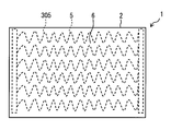
- the heat generating portion 205 meandering between the pair of electrodes 41 and 42 is employed.
- the heat generating portion 205 meanders in a rectangular wave shape.
- the shape of the heat generating portion 205 in the XY plane can also be called a key shape.
- the heat generating part 205 can provide a long energization distance.
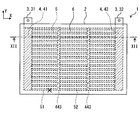
- the plurality of intermediate electrodes 443 and 443 are arranged between the electrodes 41 and 42 so as to divide the heat generating portion 5 into a plurality of portions in the length direction.
- the intermediate electrodes 443 and 443 are arranged so as to equally divide the heat generating portion 5 in the length direction.
- the intermediate electrode 443 provides an alternative energization path when a disconnection occurs in a part of the heat generating portion 5. For this reason, even if a disconnection occurs in a part of one heat generating part 5, a current can be supplied to the remaining part of the heat generating part 5. For example, when a break occurs at the mark X in the figure, the portion 51 of the heat generating portion 5 becomes unusable, but current is supplied to the portion 52 via the intermediate electrode 443. For this reason, even if partial disconnection arises, the reduction
- This embodiment is a modification based on the preceding embodiment.
- the intermediate electrode 443 is employed.
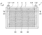
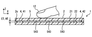
- a plurality of intermediate electrodes 543 that electrically connect only two adjacent heat generating portions 5 are employed. Even in this embodiment, it is possible to suppress a decrease in the heat generation range due to partial disconnection.
- This embodiment is a modification based on the preceding embodiment.
- the surface of the surface layer 21 is planar.
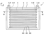
- a plurality of convex portions 624 are provided on the surface of the surface layer 21.
- the protrusion 624 is a protrusion formed on the surface layer 21.
- the convex part 624 is a thin ridge. Therefore, the convex portion 624 forms a portion on the surface of the surface layer 21 that is difficult to transfer heat from the heat generating portion 5.
- the convex portion 624 extends so as to intersect the longitudinal direction of the heat generating portion 5.
- the convex portion 624 extends over the plurality of heat generating portions 5.
- the convex parts 624 are arranged so as to be orthogonal to all the heat generating parts 5 arranged in parallel.
- the plurality of convex portions 624 partition a plurality of concave portions 625 between them.
- the plurality of convex portions 624 are arranged in parallel to each other.
- the interval between the plurality of convex portions 624 is set to be less than 5 mm.
- the substrate portion 2 includes a convex portion 624 that protrudes in the radiation direction of the radiant heat R and a concave portion 625 adjacent to the convex portion 624.
- the convex portions 624 are arranged in a distributed manner in a range where the plurality of heat generating portions 5 are arranged.
- the concave portions 625 adjacent to the convex portions 624 are also distributed on the surface.
- the object comes into contact with the surface of the surface layer 21, the object comes into contact with the top surface of the convex portion 624.
- the convex portion 624 and the concave portion 625 suppress a direct contact area between the object and the surface layer 21.
- the convex part 624 provides a long heat transfer distance.
- the recess 625 provides an air layer with high heat insulation. Thereby, the proximity of a part of the object to the high temperature part is suppressed. As a result, direct heat transfer from the radiation heater device 1 to the object is suppressed.
- This embodiment is a modification based on the preceding embodiment.
- the convex portion 624 is employed.
- a convex portion 724 is employed.
- the surface layer 21 includes a plurality of convex portions 724.
- the convex portion 724 extends in parallel with the heat generating portion 5.
- the convex part 724 is positioned immediately above the heat generating part 5.
- the convex portion 724 is provided so as to overlap the heat generating portion 5.
- the plurality of convex portions 724 define a concave portion 725 between them. Even in this configuration, the object contacts the top surface of the convex portion 724. As a result, heat transfer from the radiation heater device 1 to the object is suppressed.
- This embodiment is a modification based on the preceding embodiment.
- the convex portion 724 is employed.
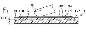
- a convex portion 824 is employed.
- the surface layer 21 includes a plurality of convex portions 824.
- the convex part 824 extends in parallel with the heat generating part 5.
- the convex portion 824 is positioned immediately above the gap 6. In other words, the convex portion 824 is provided so as not to overlap the heat generating portion 5.
- the plurality of convex portions 824 define a concave portion 825 between them. Even in this configuration, the object contacts the top surface of the convex portion 824. As a result, heat transfer from the radiation heater device 1 to the object is suppressed.
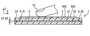
- the convex part 924 is employed.
- the surface layer 21 includes lattice-shaped convex portions 924 including a plurality of convex stripes intersecting each other.
- the convex part 924 includes a convex line extending in parallel with the heat generating part 5 and a convex line intersecting with the heat generating part 5.
- the plurality of ridges are orthogonal. Some of the ridges are positioned immediately above the heat generating portion 5. Some ridges are positioned immediately above the gap 6.
- the convex part 924 partitions the concave part 925 between them.
- the recesses 925 are independent from each other on the mesh. Even in this configuration, the object contacts the top surface of the convex portion 924. As a result, heat transfer from the radiation heater device 1 to the object is suppressed.
- This embodiment is a modification based on the preceding embodiment.
- the convex part extended elongate was employ
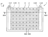
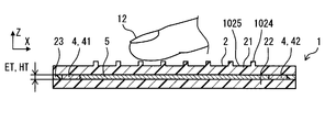
- a dot-like convex portion 1024 is employed.
- the surface layer 21 includes a plurality of convex portions 1024.
- the convex portion 1024 has a dot shape on the XY plane. Some of the convex portions 1024 are positioned immediately above the heat generating portion 5. Some of the convex portions 1024 are positioned immediately above the gap 6.
- the convex portion 1024 defines a concave portion 1025 therebetween. Even in this configuration, the object contacts the top surface of the convex portion 1024. As a result, heat transfer from the radiation heater device 1 to the object is suppressed.
- the electrode 4 and the heat generating part 5 are connected by sintering.
- the connection between the electrode 4 and the heat generating part 5 is performed by a joint using a metal joining material such as brazing, soldering, or welding, or by mechanical such as caulking or screw tightening. It may be provided by a joint using a simple connecting member.
- one unit of the radiation heater device 1 is illustrated and described.
- a single unit may be installed indoors.
- a plurality of radiation heater devices 1 may be arranged to constitute a radiation heater device array.
- the convex portions 624, 724, 824, 924, 1024 and the concave portions 625, 725, 825, 925, 1025 were formed on the surface layer 21.
- an additional layer that provides convex portions and concave portions may be added to the surface layer 21.
- the surface layer is provided by a plurality of layers.
Landscapes
- Engineering & Computer Science (AREA)
- Mechanical Engineering (AREA)
- Physics & Mathematics (AREA)
- Thermal Sciences (AREA)
- General Engineering & Computer Science (AREA)
- Chemical & Material Sciences (AREA)
- Combustion & Propulsion (AREA)
- Air-Conditioning For Vehicles (AREA)
- Resistance Heating (AREA)
- Surface Heating Bodies (AREA)
- Central Heating Systems (AREA)
Abstract
Description
図1において、第1実施形態に係る輻射ヒータ装置1は、道路走行車両、船舶、航空機などの移動体の室内に設置されている。装置1は、室内のための暖房装置10の一部を構成している。装置1は、移動体に搭載された電池、発電機などの電源から給電されて発熱する電気的なヒータである。装置1は、薄い板状に形成されている。装置1は、電力が供給されると発熱する。装置1は、その表面と垂直な方向に位置付けられた対象物を暖めるために、主としてその表面と垂直な方向へ向けて輻射熱Rを放射する。






この実施形態は、先行する実施形態を基礎的形態とする変形例である。上記実施形態では、直線状に延びる発熱部5を採用した。これに代えて、図9に図示される実施形態では、一対の電極41、42の間において蛇行する発熱部205が採用される。発熱部205は、矩形波状に蛇行している。発熱部205のX-Y平面における形状は、鍵状とも呼ぶことができる。発熱部205は長い通電距離を提供できる。
この実施形態は、先行する実施形態を基礎的形態とする変形例である。上記実施形態では、直線状に延びる発熱部5を採用した。これに代えて、図10に図示される実施形態では、一対の電極41、42の間において蛇行する発熱部305が採用される。発熱部305は、滑らかな波状に蛇行する。発熱部305は長い通電距離を提供できる。また、発熱部305は、滑らかな波状に延びるから、電流の集中を抑制する。
この実施形態は、先行する実施形態を基礎的形態とする変形例である。上記実施形態では、一対の電極41、42の間に延在する発熱部5を採用した。これに加えて、図11、図12に図示される実施形態では、一対の電極41、42の間の中間位置において、複数の発熱部5を互いに電気的に接続し短絡する中間電極443が採用される。中間電極443は、少なくとも隣接する2つの発熱部5の間を電気的に短絡する。中間電極443は、3つ以上の複数の発熱部5の間を電気的に短絡する。中間電極443は、平行に延びるすべての発熱部5の間を電気的に短絡する。この実施形態では、複数の中間電極443、443が設けられている。複数の中間電極443、443は、電極41、42の間において発熱部5を長さ方向に複数の部分に分割するように配置されている。中間電極443、443は、発熱部5を長さ方向に等分するように配置されている。
この実施形態は、先行する実施形態を基礎的形態とする変形例である。上記実施形態では、中間電極443を採用した。これに代えて、図13、図14に図示される実施形態では、隣接する2つの発熱部5だけを電気的に接続する複数の中間電極543が採用される。この実施形態でも、部分的な断線に起因する発熱範囲の減少を抑制することができる。
この実施形態は、先行する実施形態を基礎的形態とする変形例である。上記実施形態では、表面層21の表面は、平面状である。これに代えて、図15、図16に図示される実施形態では、表面層21の表面に、複数の凸部624が設けられる。凸部624は、表面層21上に形成された凸条である。凸部624は、細い凸条である。よって、凸部624は、表面層21の表面において、発熱部5からの熱を伝えにくい部分を形成する。凸部624は、発熱部5の長手方向と交差するように延びている。凸部624は、複数の発熱部5にわたって延びている。凸部624は、平行に配置されたすべての発熱部5に直交するように配置されている。
この実施形態は、先行する実施形態を基礎的形態とする変形例である。上記実施形態では、凸部624を採用した。これに代えて、図17、図18に図示される実施形態では、凸部724が採用される。表面層21は、複数の凸部724を備える。凸部724は、発熱部5と平行に延びている。凸部724は、発熱部5の直上に位置付けられている。言い換えると、凸部724は、発熱部5の上に重なるように設けられている。複数の凸部724は、それらの間に凹部725を区画している。この構成でも、物体は凸部724の頂面に接触する。この結果、輻射ヒータ装置1から物体への熱伝達が抑制される。
この実施形態は、先行する実施形態を基礎的形態とする変形例である。上記実施形態では、凸部724を採用した。これに代えて、図19、図20に図示される実施形態では、凸部824が採用される。表面層21は、複数の凸部824を備える。凸部824は、発熱部5と平行に延びている。凸部824は、隙間6の直上に位置付けられている。言い換えると、凸部824は、発熱部5の上に重ならないように設けられている。複数の凸部824は、それらの間に凹部825を区画している。この構成でも、物体は凸部824の頂面に接触する。この結果、輻射ヒータ装置1から物体への熱伝達が抑制される。
この実施形態は、先行する実施形態を基礎的形態とする変形例である。上記実施形態では、平行に延びる凸部を採用した。これに代えて、図21、図22に図示される実施形態では、格子状の凸部924が採用される。表面層21は、相互に交差する複数の凸条を含む格子状の凸部924を備える。凸部924は、発熱部5と平行に延びる凸条と、発熱部5と交差する凸条とを含む。図示の例では、複数の凸条は直交している。一部の凸条は、発熱部5の直上に位置付けられている。一部の凸条は、隙間6の直上に位置付けられている。凸部924は、それらの間に凹部925を区画している。凹部925は、網目上に互いに独立している。この構成でも、物体は凸部924の頂面に接触する。この結果、輻射ヒータ装置1から物体への熱伝達が抑制される。
この実施形態は、先行する実施形態を基礎的形態とする変形例である。上記実施形態では、細長く延びる凸部を採用した。これに代えて、図23、図24に図示される実施形態では、ドット状の凸部1024が採用される。表面層21は、複数の凸部1024を備える。凸部1024は、X-Y平面においてドット状の形状をもつ。一部の凸部1024は、発熱部5の直上に位置付けられている。一部の凸部1024は、隙間6の直上に位置付けられている。凸部1024は、それらの間に凹部1025を区画している。この構成でも、物体は凸部1024の頂面に接触する。この結果、輻射ヒータ装置1から物体への熱伝達が抑制される。
発明は上述した実施形態に何ら制限されることなく、種々変形して実施することが可能である。上記実施形態の構造、作用、効果は、あくまで例示であって、発明の技術的範囲はこれらの記載の範囲に限定されるものではない。発明は、実施形態において示された組み合わせに限定されることなく、それぞれ独立して実施可能である。発明のいくつかの技術的範囲は、特許請求の範囲の記載によって示され、さらに特許請求の範囲の記載と均等の意味及び範囲内での全ての変更を含むものである。
Claims (10)
- 電気絶縁性の材料によって表面を提供するように形成された基板部(2)と、
前記表面に沿って延びるように前記基板部に支持された一対の電極(4、41、42)と、
通電によって発熱することにより輻射熱(R)を放射するために、前記電極よりも電気的な固有抵抗が高い材料によって作られ、前記表面に沿って延びるように前記基板部に支持され、一対の前記電極の間に並列的に配置された複数の発熱部(5、205、305)とを備えることを特徴とする輻射ヒータ装置。 - 前記発熱部は、人に暖かさを感じさせる輻射熱を放射できる放射温度に到達できるように設定され、
前記発熱部の長さ方向の熱的な抵抗(Rh)は、前記表面の上において物体が接触するとき、前記物体が接触している部分の温度が、前記放射温度より低い抑制温度に低下するように設定されていることを特徴とする請求項1に記載の輻射ヒータ装置。 - 前記電極と前記発熱部とは前記基板部の内部において電気的に接合されていることを特徴とする請求項1または請求項2に記載の輻射ヒータ装置。
- 前記電極と前記発熱部とは焼結によって接合されていることを特徴とする請求項3に記載の輻射ヒータ装置。
- 前記基板部は、平板状であって、前記電極および前記発熱部は前記表面に沿って広がる膜状であることを特徴とする請求項1から請求項4のいずれかに記載の輻射ヒータ装置。
- 前記基板部は表面層(21)と裏面層(22)とを有し、前記電極と前記発熱部とは前記表面層と前記裏面層との間に配置されていることを特徴とする請求項1から請求項5のいずれかに記載の輻射ヒータ装置。
- 前記発熱部(5)は、一対の前記電極(4)の間に直線状に延びていることを特徴とする請求項1から請求項6のいずれかに記載の輻射ヒータ装置。
- 前記発熱部(205、305)は、一対の前記電極(4)の間に蛇行して延びていることを特徴とする請求項1から請求項6のいずれかに記載の輻射ヒータ装置。
- さらに、一対の前記電極(4、41、42)の間において、複数の前記発熱部(5)を電気的に短絡する中間電極(443、543)を備えることを特徴とする請求項1から請求項8のいずれかに記載の輻射ヒータ装置。
- 前記基板部は、前記輻射熱の放射方向に向けて突出する凸部(624、724、824、924、1024)および前記凸部に隣接する凹部(625、725、825、925、1025)を備えることを特徴とする請求項1から請求項9のいずれかに記載の輻射ヒータ装置。
Priority Applications (4)
| Application Number | Priority Date | Filing Date | Title |
|---|---|---|---|
| CN201480018964.7A CN105103650B (zh) | 2013-03-28 | 2014-03-17 | 辐射加热器装置 |
| DE112014001661.6T DE112014001661T5 (de) | 2013-03-28 | 2014-03-17 | Strahlungsheizungsvorrichtung |
| US14/780,369 US20160059669A1 (en) | 2013-03-28 | 2014-03-17 | Radiant heater device |
| US16/537,646 US20190359032A1 (en) | 2013-03-28 | 2019-08-12 | Radiant heater device |
Applications Claiming Priority (2)
| Application Number | Priority Date | Filing Date | Title |
|---|---|---|---|
| JP2013-069338 | 2013-03-28 | ||
| JP2013069338A JP5983495B2 (ja) | 2013-03-28 | 2013-03-28 | 輻射ヒータ装置 |
Related Child Applications (2)
| Application Number | Title | Priority Date | Filing Date |
|---|---|---|---|
| US14/780,369 A-371-Of-International US20160059669A1 (en) | 2013-03-28 | 2014-03-17 | Radiant heater device |
| US16/537,646 Division US20190359032A1 (en) | 2013-03-28 | 2019-08-12 | Radiant heater device |
Publications (1)
| Publication Number | Publication Date |
|---|---|
| WO2014156038A1 true WO2014156038A1 (ja) | 2014-10-02 |
Family
ID=51623056
Family Applications (1)
| Application Number | Title | Priority Date | Filing Date |
|---|---|---|---|
| PCT/JP2014/001487 Ceased WO2014156038A1 (ja) | 2013-03-28 | 2014-03-17 | 輻射ヒータ装置 |
Country Status (5)
| Country | Link |
|---|---|
| US (2) | US20160059669A1 (ja) |
| JP (1) | JP5983495B2 (ja) |
| CN (1) | CN105103650B (ja) |
| DE (1) | DE112014001661T5 (ja) |
| WO (1) | WO2014156038A1 (ja) |
Cited By (4)
| Publication number | Priority date | Publication date | Assignee | Title |
|---|---|---|---|---|
| US9873309B2 (en) | 2013-04-12 | 2018-01-23 | Denso Corporation | Radiant heater air-conditioning system |
| CN109952810A (zh) * | 2016-11-16 | 2019-06-28 | 株式会社电装 | 辐射加热装置 |
| TWI706689B (zh) * | 2015-11-27 | 2020-10-01 | 日商美鈴工業股份有限公司 | 加熱器、定著裝置、畫像形成裝置以及加熱裝置 |
| WO2025192290A1 (ja) * | 2024-03-11 | 2025-09-18 | 株式会社デンソー | フィルムヒータ |
Families Citing this family (63)
| Publication number | Priority date | Publication date | Assignee | Title |
|---|---|---|---|---|
| JP6127913B2 (ja) | 2013-03-29 | 2017-05-17 | 株式会社デンソー | 輻射ヒータ装置 |
| JP6245101B2 (ja) | 2014-07-22 | 2017-12-13 | 株式会社デンソー | 輻射ヒータ装置 |
| JP6447245B2 (ja) | 2014-07-25 | 2019-01-09 | 株式会社デンソー | 輻射ヒータ装置 |
| KR20160070869A (ko) * | 2014-12-10 | 2016-06-21 | 현대자동차주식회사 | 차량의 히팅패널 |
| JP6435828B2 (ja) | 2014-12-10 | 2018-12-12 | 株式会社デンソー | ヒータ装置 |
| WO2016117376A1 (ja) * | 2015-01-19 | 2016-07-28 | 株式会社デンソー | ヒータ装置 |
| JP6296175B2 (ja) * | 2015-01-22 | 2018-03-20 | 株式会社デンソー | ヒータ装置 |
| DE102015110666B4 (de) | 2015-07-02 | 2024-02-01 | Dr. Ing. H.C. F. Porsche Aktiengesellschaft | Heizvorrichtung |
| KR102238056B1 (ko) * | 2015-07-03 | 2021-04-09 | 현대자동차주식회사 | 차량용 복사열 히터 |
| WO2017047982A1 (ko) * | 2015-09-14 | 2017-03-23 | 한온시스템 주식회사 | 차량용 복사열 히터 |
| CN107926081B (zh) | 2015-09-15 | 2021-07-09 | 株式会社电装 | 加热器装置 |
| KR101755919B1 (ko) * | 2015-12-08 | 2017-07-07 | 현대자동차주식회사 | 배터리용 발열기구 |
| JP6447753B2 (ja) * | 2016-01-25 | 2019-01-09 | 株式会社デンソー | ヒータ装置 |
| JP6703872B2 (ja) | 2016-03-28 | 2020-06-03 | 日本碍子株式会社 | ヒータ及びそのヒータを備えるハニカム構造体 |
| CN106137739A (zh) * | 2016-08-29 | 2016-11-23 | 曾庆程 | 用于人体热灸的红外发生装置 |
| KR101745276B1 (ko) | 2016-09-05 | 2017-06-09 | 현대자동차주식회사 | 차량의 히팅패널 |
| WO2018116659A1 (ja) | 2016-12-20 | 2018-06-28 | 株式会社デンソー | 輻射ヒータ装置 |
| FR3065671B1 (fr) | 2017-04-28 | 2020-05-08 | Valeo Systemes Thermiques | Dispositif de chauffage pour un vehicule automobile |
| US10752090B2 (en) | 2017-08-10 | 2020-08-25 | Ford Global Technologies, Llc | Operator configurable radiant heating system and related method |
| FR3084293B1 (fr) | 2018-07-30 | 2022-09-23 | Valeo Systemes Thermiques | Panneau radiant |
| JP2020117070A (ja) * | 2019-01-23 | 2020-08-06 | 本田技研工業株式会社 | 移動体用制御装置 |
| JP7066645B2 (ja) * | 2019-01-23 | 2022-05-13 | 本田技研工業株式会社 | 移動体用制御装置 |
| JP7135964B2 (ja) | 2019-03-26 | 2022-09-13 | 株式会社デンソー | ヒータ装置 |
| FR3095734A1 (fr) | 2019-04-30 | 2020-11-06 | Valeo Systemes Thermiques | Structure chauffante pour véhicule automobile |
| CN110173890A (zh) * | 2019-05-07 | 2019-08-27 | 上海理工大学 | 玻璃钢箱体的电极加热装置 |
| FR3096219B1 (fr) | 2019-05-13 | 2021-04-30 | Valeo Systemes Thermiques | Structure chauffante pour véhicule automobile |
| FR3098370A1 (fr) | 2019-07-02 | 2021-01-08 | Valeo Systemes Thermiques | Structure chauffante pour véhicule automobile |
| FR3098678A1 (fr) | 2019-07-12 | 2021-01-15 | Valeo Systemes Thermiques | Structure chauffante pour véhicule automobile |
| FR3099334A1 (fr) | 2019-07-22 | 2021-01-29 | Valeo Systemes Thermiques | Structure chauffante pour véhicule automobile |
| FR3101224B1 (fr) | 2019-09-19 | 2023-05-26 | Valeo Systemes Thermiques | Structure chauffante pour véhicule automobile |
| FR3101283B1 (fr) | 2019-09-27 | 2021-10-01 | Valeo Systemes Thermiques | Structure chauffante pour véhicule automobile |
| KR102199815B1 (ko) * | 2019-10-10 | 2021-01-07 | 주식회사 테라온 | 접촉식 스위치가 구비된 면상 발열 히터 |
| FR3102908A1 (fr) | 2019-11-06 | 2021-05-07 | Valeo Systemes Thermiques | Structure chauffante pour véhicule automobile |
| FR3116408B1 (fr) | 2020-11-19 | 2023-10-27 | Valeo Systemes Thermiques | Structure chauffante pour véhicule automobile |
| CN113543383B (zh) * | 2021-07-30 | 2023-03-28 | 东风商用车有限公司 | 一种加热垫及其制作方法 |
| FR3131171A1 (fr) | 2021-12-16 | 2023-06-23 | Valeo Systemes Thermiques | Dispositif chauffant pour habitacle de véhicule |
| FR3140307A1 (fr) | 2022-09-30 | 2024-04-05 | Valeo Systemes Thermiques | Dispositif de chauffage et d’éclairage, notamment pour véhicule |
| FR3140509B1 (fr) | 2022-09-30 | 2024-10-25 | Valeo Systemes Thermiques | Dispositif de chauffage et d’éclairage, notamment pour véhicule |
| FR3140308A1 (fr) | 2022-09-30 | 2024-04-05 | Valeo Systemes Thermiques | Dispositif de chauffage et d’éclairage, notamment pour véhicule |
| FR3140511B3 (fr) | 2022-09-30 | 2024-10-18 | Valeo Vision | Dispositif de chauffage et d’éclairage, notamment pour véhicule |
| FR3140510B3 (fr) | 2022-09-30 | 2024-10-18 | Valeo Vision | Dispositif de chauffage et d’éclairage, notamment pour véhicule |
| FR3141588A1 (fr) | 2022-10-28 | 2024-05-03 | Valeo Vision | Dispositif de chauffage et d’éclairage, notamment pour véhicule |
| FR3141587A3 (fr) | 2022-10-28 | 2024-05-03 | Valeo Vision | Dispositif de chauffage et d’éclairage, notamment pour véhicule |
| FR3142695B1 (fr) | 2022-12-02 | 2025-09-05 | Dav | Système de confort interactif, notamment pour véhicule |
| FR3142720A1 (fr) | 2022-12-02 | 2024-06-07 | Valeo Systemes Thermiques | Système de confort interactif, notamment pour véhicule |
| FR3142697B1 (fr) | 2022-12-02 | 2025-09-05 | Dav | Système de confort interactif, notamment pour véhicule |
| FR3142696B1 (fr) | 2022-12-02 | 2025-09-05 | Dav | Système de confort interactif, notamment pour véhicule |
| FR3142862A1 (fr) | 2022-12-02 | 2024-06-07 | Dav | Système de chauffage, notamment pour véhicule |
| FR3142698B1 (fr) | 2022-12-02 | 2025-10-24 | Valeo Systemes Thermiques | Système de confort interactif, notamment pour véhicule |
| FR3143636A1 (fr) | 2022-12-20 | 2024-06-21 | Valeo Vision | Dispositif de chauffage et d’éclairage, notamment pour véhicule |
| FR3144554A3 (fr) | 2022-12-31 | 2024-07-05 | Valeo Vision | Dispositif de chauffage et d’éclairage, notamment pour véhicule |
| FR3144552B1 (fr) | 2022-12-31 | 2025-04-18 | Valeo Vision | Dispositif de chauffage et d’éclairage, notamment pour véhicule |
| FR3144551A3 (fr) | 2022-12-31 | 2024-07-05 | Valeo Vision | Dispositif de chauffage et d’éclairage, notamment pour véhicule |
| FR3144553B1 (fr) | 2022-12-31 | 2025-04-18 | Valeo Vision | Dispositif de chauffage et d’éclairage, notamment pour véhicule |
| FR3151962A1 (fr) | 2023-08-03 | 2025-02-07 | Valeo Systemes Thermiques | Structure chauffante destinée à être installée à l’intérieur d’un habitacle d’un véhicule |
| FR3151961A1 (fr) | 2023-08-03 | 2025-02-07 | Valeo Systemes Thermiques | Structure chauffante, notamment pour habitacle de véhicule |
| WO2025073363A1 (fr) | 2023-10-04 | 2025-04-10 | Valeo Systemes Thermiques | Dispositif de chauffage et d'éclairage, notamment pour véhicule |
| WO2025077997A1 (fr) | 2023-10-09 | 2025-04-17 | Valeo Systemes Thermiques | Dispositif de chauffage et d'éclairage, notamment pour véhicule |
| FR3154277A1 (fr) | 2023-10-11 | 2025-04-18 | Valeo Systemes Thermiques | Système de confort interactif, notamment pour véhicule |
| FR3158404A1 (fr) | 2024-01-17 | 2025-07-18 | Valeo Systemes Thermiques | Système de confort interactif, notamment pour véhicule |
| FR3158912A1 (fr) | 2024-02-07 | 2025-08-08 | Valeo Systemes Thermiques | Système de confort interactif |
| FR3160082A1 (fr) | 2024-03-08 | 2025-09-12 | Valeo Systemes Thermiques | Système de confort interactif, notamment pour véhicule |
| FR3161014A1 (fr) | 2024-07-18 | 2025-10-10 | Valeo Vision | Dispositif d’éclairage, notamment pour véhicule automobile |
Citations (8)
| Publication number | Priority date | Publication date | Assignee | Title |
|---|---|---|---|---|
| JPS6335285U (ja) * | 1986-08-26 | 1988-03-07 | ||
| JPH09161959A (ja) * | 1995-12-12 | 1997-06-20 | Matsushita Electric Ind Co Ltd | 面状発熱体 |
| JP2000215968A (ja) * | 1999-01-21 | 2000-08-04 | Toransu Global:Kk | 電熱シ―ト |
| JP2002175870A (ja) * | 2000-09-29 | 2002-06-21 | Toto Ltd | 面状ヒータ及びその製造方法 |
| JP2012056531A (ja) * | 2010-09-13 | 2012-03-22 | Denso Corp | 車両用輻射熱暖房装置 |
| JP2012228896A (ja) * | 2011-04-25 | 2012-11-22 | Denso Corp | 車両用輻射熱暖房装置 |
| JP2014000944A (ja) * | 2012-05-23 | 2014-01-09 | Denso Corp | 輻射ヒータ装置 |
| JP2014082126A (ja) * | 2012-10-17 | 2014-05-08 | Denso Corp | 輻射ヒータ装置 |
Family Cites Families (5)
| Publication number | Priority date | Publication date | Assignee | Title |
|---|---|---|---|---|
| JP2898364B2 (ja) * | 1990-07-06 | 1999-05-31 | 日本碍子株式会社 | 電極一体型ハニカムヒーター及びその製造方法 |
| GB0321916D0 (en) * | 2003-09-19 | 2003-10-22 | Heatsafe Cable Systems Ltd | Self-regulating electrical heating cable |
| JP2006261095A (ja) * | 2005-02-15 | 2006-09-28 | Ngk Insulators Ltd | 面状ヒータ装置 |
| JP5522943B2 (ja) * | 2008-01-29 | 2014-06-18 | 京セラ株式会社 | 熱電モジュール |
| CA2735664A1 (en) * | 2008-09-16 | 2010-03-25 | United States Gypsum Company | Heating system |
-
2013
- 2013-03-28 JP JP2013069338A patent/JP5983495B2/ja active Active
-
2014
- 2014-03-17 WO PCT/JP2014/001487 patent/WO2014156038A1/ja not_active Ceased
- 2014-03-17 CN CN201480018964.7A patent/CN105103650B/zh not_active Expired - Fee Related
- 2014-03-17 DE DE112014001661.6T patent/DE112014001661T5/de not_active Ceased
- 2014-03-17 US US14/780,369 patent/US20160059669A1/en not_active Abandoned
-
2019
- 2019-08-12 US US16/537,646 patent/US20190359032A1/en not_active Abandoned
Patent Citations (8)
| Publication number | Priority date | Publication date | Assignee | Title |
|---|---|---|---|---|
| JPS6335285U (ja) * | 1986-08-26 | 1988-03-07 | ||
| JPH09161959A (ja) * | 1995-12-12 | 1997-06-20 | Matsushita Electric Ind Co Ltd | 面状発熱体 |
| JP2000215968A (ja) * | 1999-01-21 | 2000-08-04 | Toransu Global:Kk | 電熱シ―ト |
| JP2002175870A (ja) * | 2000-09-29 | 2002-06-21 | Toto Ltd | 面状ヒータ及びその製造方法 |
| JP2012056531A (ja) * | 2010-09-13 | 2012-03-22 | Denso Corp | 車両用輻射熱暖房装置 |
| JP2012228896A (ja) * | 2011-04-25 | 2012-11-22 | Denso Corp | 車両用輻射熱暖房装置 |
| JP2014000944A (ja) * | 2012-05-23 | 2014-01-09 | Denso Corp | 輻射ヒータ装置 |
| JP2014082126A (ja) * | 2012-10-17 | 2014-05-08 | Denso Corp | 輻射ヒータ装置 |
Cited By (5)
| Publication number | Priority date | Publication date | Assignee | Title |
|---|---|---|---|---|
| US9873309B2 (en) | 2013-04-12 | 2018-01-23 | Denso Corporation | Radiant heater air-conditioning system |
| TWI706689B (zh) * | 2015-11-27 | 2020-10-01 | 日商美鈴工業股份有限公司 | 加熱器、定著裝置、畫像形成裝置以及加熱裝置 |
| CN109952810A (zh) * | 2016-11-16 | 2019-06-28 | 株式会社电装 | 辐射加热装置 |
| CN109952810B (zh) * | 2016-11-16 | 2022-01-11 | 株式会社电装 | 辐射加热装置 |
| WO2025192290A1 (ja) * | 2024-03-11 | 2025-09-18 | 株式会社デンソー | フィルムヒータ |
Also Published As
| Publication number | Publication date |
|---|---|
| JP5983495B2 (ja) | 2016-08-31 |
| DE112014001661T5 (de) | 2015-12-10 |
| US20190359032A1 (en) | 2019-11-28 |
| JP2014189251A (ja) | 2014-10-06 |
| CN105103650A (zh) | 2015-11-25 |
| CN105103650B (zh) | 2017-05-10 |
| US20160059669A1 (en) | 2016-03-03 |
Similar Documents
| Publication | Publication Date | Title |
|---|---|---|
| JP5983495B2 (ja) | 輻射ヒータ装置 | |
| JP6245101B2 (ja) | 輻射ヒータ装置 | |
| JP5895805B2 (ja) | 輻射ヒータ装置 | |
| JP6771167B2 (ja) | 組み込まれた温度センサを有する加熱装置 | |
| JP2019184171A (ja) | ヒータ装置 | |
| JP6725005B2 (ja) | 輻射ヒータ装置 | |
| CN111213431B (zh) | 加热器装置 | |
| WO2017047301A1 (ja) | ヒータ装置 | |
| JP6296175B2 (ja) | ヒータ装置 | |
| CN113228823B (zh) | 具有熔断功能的发热元件及包括此的加热单元 | |
| JP2016034791A (ja) | 車両用暖房装置 | |
| TW202137812A (zh) | 具有柔性印刷布線板的加熱器及其製造方法 | |
| JP5842782B2 (ja) | 輻射ヒータ装置 | |
| KR20140041980A (ko) | 면상 발열체 | |
| WO2021210677A1 (ja) | ヒータ装置 | |
| JP2006269241A (ja) | ヒータミラー | |
| JP6669271B2 (ja) | 輻射ヒータ装置 | |
| CN115399068A (zh) | 加热器装置 | |
| US12543246B2 (en) | Heater device | |
| WO2019078090A1 (ja) | ヒータ装置 | |
| JP2010272246A (ja) | ミラー用面状ヒータ | |
| JP2010076686A (ja) | 車両用の電気毛布 | |
| JP2008181833A (ja) | 加熱体 |
Legal Events
| Date | Code | Title | Description |
|---|---|---|---|
| WWE | Wipo information: entry into national phase |
Ref document number: 201480018964.7 Country of ref document: CN |
|
| 121 | Ep: the epo has been informed by wipo that ep was designated in this application |
Ref document number: 14774184 Country of ref document: EP Kind code of ref document: A1 |
|
| WWE | Wipo information: entry into national phase |
Ref document number: 14780369 Country of ref document: US |
|
| WWE | Wipo information: entry into national phase |
Ref document number: 1120140016616 Country of ref document: DE Ref document number: 112014001661 Country of ref document: DE |
|
| 122 | Ep: pct application non-entry in european phase |
Ref document number: 14774184 Country of ref document: EP Kind code of ref document: A1 |