WO2014155708A1 - リチウムイオン二次電池用正極材料、リチウムイオン二次電池用正極、及びリチウムイオン二次電池 - Google Patents
リチウムイオン二次電池用正極材料、リチウムイオン二次電池用正極、及びリチウムイオン二次電池 Download PDFInfo
- Publication number
- WO2014155708A1 WO2014155708A1 PCT/JP2013/059632 JP2013059632W WO2014155708A1 WO 2014155708 A1 WO2014155708 A1 WO 2014155708A1 JP 2013059632 W JP2013059632 W JP 2013059632W WO 2014155708 A1 WO2014155708 A1 WO 2014155708A1
- Authority
- WO
- WIPO (PCT)
- Prior art keywords
- ion secondary
- lithium ion
- positive electrode
- secondary battery
- electrode material
- Prior art date
Links
Images


Classifications
-
- H—ELECTRICITY
- H01—ELECTRIC ELEMENTS
- H01M—PROCESSES OR MEANS, e.g. BATTERIES, FOR THE DIRECT CONVERSION OF CHEMICAL ENERGY INTO ELECTRICAL ENERGY
- H01M4/00—Electrodes
- H01M4/02—Electrodes composed of, or comprising, active material
- H01M4/13—Electrodes for accumulators with non-aqueous electrolyte, e.g. for lithium-accumulators; Processes of manufacture thereof
- H01M4/131—Electrodes based on mixed oxides or hydroxides, or on mixtures of oxides or hydroxides, e.g. LiCoOx
-
- H—ELECTRICITY
- H01—ELECTRIC ELEMENTS
- H01M—PROCESSES OR MEANS, e.g. BATTERIES, FOR THE DIRECT CONVERSION OF CHEMICAL ENERGY INTO ELECTRICAL ENERGY
- H01M10/00—Secondary cells; Manufacture thereof
- H01M10/05—Accumulators with non-aqueous electrolyte
- H01M10/052—Li-accumulators
-
- H—ELECTRICITY
- H01—ELECTRIC ELEMENTS
- H01M—PROCESSES OR MEANS, e.g. BATTERIES, FOR THE DIRECT CONVERSION OF CHEMICAL ENERGY INTO ELECTRICAL ENERGY
- H01M4/00—Electrodes
- H01M4/02—Electrodes composed of, or comprising, active material
- H01M4/36—Selection of substances as active materials, active masses, active liquids
- H01M4/48—Selection of substances as active materials, active masses, active liquids of inorganic oxides or hydroxides
- H01M4/50—Selection of substances as active materials, active masses, active liquids of inorganic oxides or hydroxides of manganese
- H01M4/505—Selection of substances as active materials, active masses, active liquids of inorganic oxides or hydroxides of manganese of mixed oxides or hydroxides containing manganese for inserting or intercalating light metals, e.g. LiMn2O4 or LiMn2OxFy
-
- H—ELECTRICITY
- H01—ELECTRIC ELEMENTS
- H01M—PROCESSES OR MEANS, e.g. BATTERIES, FOR THE DIRECT CONVERSION OF CHEMICAL ENERGY INTO ELECTRICAL ENERGY
- H01M4/00—Electrodes
- H01M4/02—Electrodes composed of, or comprising, active material
- H01M4/36—Selection of substances as active materials, active masses, active liquids
- H01M4/48—Selection of substances as active materials, active masses, active liquids of inorganic oxides or hydroxides
- H01M4/52—Selection of substances as active materials, active masses, active liquids of inorganic oxides or hydroxides of nickel, cobalt or iron
- H01M4/525—Selection of substances as active materials, active masses, active liquids of inorganic oxides or hydroxides of nickel, cobalt or iron of mixed oxides or hydroxides containing iron, cobalt or nickel for inserting or intercalating light metals, e.g. LiNiO2, LiCoO2 or LiCoOxFy
-
- Y—GENERAL TAGGING OF NEW TECHNOLOGICAL DEVELOPMENTS; GENERAL TAGGING OF CROSS-SECTIONAL TECHNOLOGIES SPANNING OVER SEVERAL SECTIONS OF THE IPC; TECHNICAL SUBJECTS COVERED BY FORMER USPC CROSS-REFERENCE ART COLLECTIONS [XRACs] AND DIGESTS
- Y02—TECHNOLOGIES OR APPLICATIONS FOR MITIGATION OR ADAPTATION AGAINST CLIMATE CHANGE
- Y02E—REDUCTION OF GREENHOUSE GAS [GHG] EMISSIONS, RELATED TO ENERGY GENERATION, TRANSMISSION OR DISTRIBUTION
- Y02E60/00—Enabling technologies; Technologies with a potential or indirect contribution to GHG emissions mitigation
- Y02E60/10—Energy storage using batteries
Definitions
- the present invention relates to a positive electrode material for a lithium ion secondary battery, a positive electrode for a lithium ion secondary battery using the positive electrode material for the lithium ion secondary battery, and a lithium ion secondary battery using the positive electrode for the lithium ion secondary battery.
- a positive electrode material for a lithium ion secondary battery a positive electrode for a lithium ion secondary battery using the positive electrode material for the lithium ion secondary battery
- a lithium ion secondary battery using the positive electrode for the lithium ion secondary battery using the positive electrode for the lithium ion secondary battery.
- a lithium ion secondary battery used in an electric vehicle is required to have a high capacity.
- Patent Document 1 discloses lithium using a positive electrode material in which a lithium-containing transition metal oxide having a hexagonal layered rock salt crystal structure belonging to space group R-3m and a lithium manganese oxide having a spinel structure are mixed. An ion secondary battery is described.
- the positive electrode material for a lithium ion secondary battery disclosed in Patent Document 1 has a problem of high capacity but large irreversible capacity.
- a positive electrode material having a large irreversible capacity is used for a battery, an amount of a negative electrode having a capacity corresponding to the initial large charge capacity is required. Therefore, a battery having a large irreversible capacity has a problem that the volume and weight per unit capacity increase as the amount of the negative electrode increases.
- an object of the present invention is to provide a positive electrode material for a lithium ion secondary battery having high capacity and low irreversible capacity.
- the positive electrode material for a lithium ion secondary battery of the present invention has a composition formula: xLiNi a Mn 1-a O 2 —yLi 4 O 2 — (1-xy) MnO 2 [Wherein x, y, and a are the following relationships: ⁇ 0.5x + 0.41 ⁇ y ⁇ 0.5x + 0.49, -0.1x + 0.13 ⁇ y ⁇ -0.1x + 0.21, 0.2 ⁇ a ⁇ 0.6 It is a parameter that satisfies
- a positive electrode material for a lithium ion secondary battery having a high capacity and a small irreversible capacity can be provided.
- FIG. 1 is a ternary phase diagram showing a composition range of a positive electrode material for a lithium ion secondary battery according to an example of the present invention.
- FIG. 2 is a cross-sectional view schematically showing the structure of the lithium ion secondary battery.
- FIG. 3 is a list showing the compositions of Examples and Comparative Examples.
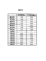
- FIG. 4 is a list showing values of the discharge capacity ratio and the irreversible capacity ratio obtained for the examples and comparative examples.
- ⁇ Positive electrode material for lithium ion secondary battery> When adopting lithium ion secondary batteries in electric vehicles, it is necessary to improve the energy density per unit volume and unit weight of the battery, and to increase the distance that can be traveled by one charge in a limited volume and weight. Is done. In order to realize such characteristics, the positive electrode material for a lithium ion secondary battery is required to have a high capacity and a small irreversible capacity.
- Irreversible capacity is the difference between the initial charge capacity and discharge capacity.
- the battery needs a negative electrode that matches the charge capacity of the positive electrode.However, in a battery with a large irreversible capacity, the discharge capacity that can actually be used is smaller than the charge capacity. Will increase in volume and weight. Therefore, by reducing the irreversible capacity, the volume and weight of the battery per unit capacity can be reduced. By reducing the volume and weight of the battery per unit capacity, the energy density per unit volume and per unit weight can be improved.
- the positive electrode material for a lithium ion secondary battery according to the present invention has a composition formula: xLiNi a Mn 1-a O 2 —yLi 4 O 2 — (1-xy) MnO 2 [Wherein x, y, and a are the following relationships: ⁇ 0.5x + 0.41 ⁇ y ⁇ 0.5x + 0.49, -0.1x + 0.13 ⁇ y ⁇ -0.1x + 0.21, 0.2 ⁇ a ⁇ 0.6 It is a parameter that satisfies
- the positive electrode material of the present invention is represented by a combination of LiNi a Mn 1-a O 2 , Li 4 O 2, and MnO 2 for convenience, but each does not form a different phase and is integrated. It is a compound having a composition.
- FIG. 1 is a ternary phase diagram of LiNi a Mn 1-a O 2 , Li 4 O 2 , and MnO 2 with respect to the composition range of the above composition formula.
- the range shown by diagonal lines represents the composition range according to the above composition formula.
- x is a parameter indicating the ratio of LiNi a Mn 1-a O 2 .
- x is 0.5 or less, the discharge capacity at a high potential decreases. This is considered to be because LiNi a Mn 1-a O 2 as a component that reacts at a high potential decreases.
- x is 0.9 or more, a high capacity cannot be obtained. This is because the amount of LiNi a Mn 1-a O 2 increases and most of the positive electrode material for lithium ion secondary batteries becomes a layered component, so that the reaction involving oxygen in the positive electrode for lithium ion secondary batteries is less likely to occur. This is probably because of this.
- y represents the ratio of Li 4 O 2 .
- y needs to satisfy the relationship of ⁇ 0.5x + 0.41 ⁇ y ⁇ 0.5x + 0.49 and ⁇ 0.1x + 0.13 ⁇ y ⁇ 0.1x + 0.21.
- a represents the ratio of Ni in LiNi a Mn 1-a O 2 .
- a 0.2 or less, the capacity decreases. This is presumably because a sufficient capacity cannot be obtained because the proportion of Ni involved in the reaction is relatively small.
- a 0.6 or more, the irreversible capacity increases. This is presumably because the proportion of Mn required for oxygen participation in the discharge reaction is relatively small.
- x, y, and a in the above composition formula have the following relationship: ⁇ 0.5x + 0.41 ⁇ y ⁇ 0.5x + 0.49, -0.1x + 0.13 ⁇ y ⁇ -0.1x + 0.21, 0.3 ⁇ a ⁇ 0.5 It is preferable to satisfy.
- X, y, and a are each of these conditions, that is, ⁇ 0.5x + 0.41 ⁇ y ⁇ 0.5x + 0.49, -0.1x + 0.13 ⁇ y ⁇ -0.1x + 0.21, 0.3 ⁇ a ⁇ 0.5 And satisfy 0.6 ⁇ x ⁇ 0.8 It is more preferable to satisfy the requirements in terms of high capacity and reduced irreversible capacity.
- the positive electrode material for a lithium ion secondary battery of the present invention basically contains three kinds of elements of Li, Ni, and Mn as transition metals, and does not contain expensive Co. Therefore, the positive electrode material for a lithium ion secondary battery of the present invention has an advantage of low cost. In addition, the positive electrode material for a lithium ion secondary battery of the present invention may contain an additive or the like as long as it does not affect the present invention.
- the positive electrode material for a lithium ion secondary battery according to the present invention can be produced by a method generally used in the technical field to which the present invention belongs. For example, it can be produced by mixing and firing a compound containing Li, Ni, and Mn at an appropriate ratio. By changing the mixing ratio of the above compounds, the ratio of LiNi a Mn 1-a O 2 , Li 4 O 2 and MnO 2 can be adjusted as appropriate.
- Examples of the compound containing Li include lithium acetate, lithium nitrate, lithium carbonate, lithium hydroxide, and lithium oxide.
- Examples of the compound containing Ni include nickel acetate, nickel nitrate, nickel carbonate, nickel sulfate, and nickel hydroxide.
- Examples of the compound containing Mn include manganese acetate, manganese nitrate, manganese carbonate, manganese sulfate, manganese oxide, and the like.
- the structure and composition of the positive electrode material for a lithium ion secondary battery can be analyzed by, for example, X-ray diffraction (XRD) or inductively coupled plasma method (ICP).
- XRD X-ray diffraction
- ICP inductively coupled plasma method
- the positive electrode for a lithium ion secondary battery according to the present invention is produced using the above positive electrode material for a lithium ion secondary battery. Thereby, a positive electrode for a lithium ion secondary battery having a high capacity and a small irreversible capacity can be realized.
- the lithium ion secondary battery which concerns on this invention is produced using said positive electrode for lithium ion secondary batteries. Accordingly, a lithium ion secondary battery having a high capacity, a small irreversible capacity, and a reduced volume and weight per unit capacity can be obtained.
- the lithium ion secondary battery according to the present invention can be preferably used for electric vehicles and plug-in hybrid vehicles. It can also be used for power storage systems, power tools, toys, medical equipment, and the like.
- a lithium ion secondary battery includes a positive electrode including a positive electrode material, a negative electrode including a negative electrode material, a separator, an electrolytic solution, an electrolyte, and the like.
- the negative electrode material is not particularly limited as long as it is a substance that can occlude and release lithium ions.
- Substances generally used in lithium ion secondary batteries can be used as the negative electrode material.
- graphite, a lithium alloy, etc. can be illustrated.
- separator those commonly used in lithium ion secondary batteries can be used.
- examples thereof include microporous films and nonwoven fabrics made from polyolefins such as polypropylene, polyethylene, and a copolymer of propylene and ethylene.
- electrolytic solution and the electrolyte those generally used in lithium ion secondary batteries can be used.
- diethyl carbonate, dimethyl carbonate, ethylene carbonate, propylene carbonate, vinylene carbonate, methyl acetate, ethyl methyl carbonate, methyl propyl carbonate, dimethoxyethane and the like can be exemplified as the electrolytic solution.
- LiClO 4 LiPF 6 , LiBF 4 , LiAsF 6 , LiSbF 6 , LiCF 3 SO 3 , LiC 4 F 9 SO 3 , LiCF 3 CO 2 , Li 2 C 2 F 4 (SO 3 ) 2 , LiN (CF 3 SO 2 ) 2 , LiC (CF 3 SO 2 ) 3 and the like can be exemplified.
- the lithium ion secondary battery 10 includes an electrode group having a positive electrode 1 in which a positive electrode material is applied on both sides of a current collector, a negative electrode 2 in which a negative electrode material is applied on both sides of the current collector, and a separator 3.
- the positive electrode 1 and the negative electrode 2 are wound through a separator 3 to form a wound electrode group. This wound body is inserted into the battery can 4.
- the negative electrode 2 is electrically connected to the battery can 4 via the negative electrode lead piece 6.
- a sealing lid 7 is attached to the battery can 4 via a packing 8.
- the positive electrode 1 is electrically connected to the sealing lid 7 through the positive electrode lead piece 5.
- the wound body is insulated from the battery can 4 and the sealing lid 7 by the insulating plate 9.
- the electrode group may not be the wound body shown in FIG. 2, but may be a laminated body in which the positive electrode 1 and the negative electrode 2 are laminated via the separator 3.
- the composition was adjusted by variously changing the mixing ratio of lithium carbonate, nickel carbonate, and manganese carbonate, and the composition formula xLiNi a Mn 1-a O 2 —yLi 4 O 2 — (1-xy) MnO 2
- the represented positive electrode material was obtained.
- Fig. 3 shows the composition of the prepared positive electrode material as a list.
- a positive electrode slurry, a conductive agent, and a binder were mixed uniformly to prepare a positive electrode slurry.
- a positive electrode slurry was applied onto an aluminum current collector foil having a thickness of 20 ⁇ m, dried at 120 ° C., and compression-molded so as to have an electrode density of 2.2 g / cm 3 with a press device to obtain an electrode plate. Thereafter, the electrode plate was punched into a disk shape having a diameter of 15 mm to produce a positive electrode.
- the negative electrode was produced using metallic lithium.
- a solution obtained by dissolving LiPF 6 at a concentration of 1.0 mol / L in a mixed solvent of ethylene carbonate and dimethyl carbonate having a volume ratio of 1: 2 was used.
- the positive electrode material for a lithium ion secondary battery has a composition formula: In xLiNi a Mn 1-a O 2 —yLi 4 O 2 — (1-xy) MnO 2 , x, y, and a have the following relationship: ⁇ 0.5x + 0.41 ⁇ y ⁇ 0.5x + 0.49, -0.1x + 0.13 ⁇ y ⁇ -0.1x + 0.21, According to the positive electrode material for lithium ion secondary satisfying 0.2 ⁇ a ⁇ 0.6, it can be seen that a lithium ion secondary battery having a high capacity and a small irreversible capacity can be realized.
- the positive electrode material for a lithium ion secondary battery has a composition formula: In xLiNi a Mn 1-a O 2 —yLi 4 O 2 — (1-xy) MnO 2 , x, y, and a have the following relationship: ⁇ 0.5x + 0.41 ⁇ y ⁇ 0.5x + 0.49, -0.1x + 0.13 ⁇ y ⁇ -0.1x + 0.21, 0.3 ⁇ a ⁇ 0.5, 0.6 ⁇ x ⁇ 0.8 According to the positive electrode material for lithium ion secondary that satisfies the above, it can be seen that a lithium ion secondary battery having a high capacity and a small irreversible capacity can be realized.
- Comparative Example 2 has a small discharge capacity ratio. This is presumably because there are few components of LiNi a Mn 1-a O 2 that contribute to the discharge reaction in the high potential region.
- Comparative Example 6 has a small discharge capacity. This is presumably because the proportion of Ni contributing to the discharge reaction at a high potential is small.
- Comparative Example 7 has a small discharge capacity. This is presumably because the involvement of oxygen in the discharge reaction was inhibited due to the small amount of Mn.
- a positive electrode material for a lithium ion secondary battery having a high capacity and a small irreversible capacity can be provided at low cost.
- a lithium ion secondary battery with reduced volume and weight per unit capacity can be provided at low cost.
Abstract
リチウムイオン二次電池用正極材料は、組成式: xLiNiaMn1-aO2-yLi4O2-(1-y-z)MnO2 [式中、x、y、及びaは次の関係: -0.5x+0.41<y<-0.5x+0.49、 -0.1x+0.13<y<-0.1x+0.21、 0.2<a<0.6 を満たすパラメータである] で表される。
Description
本発明は、リチウムイオン二次電池用正極材料、そのリチウムイオン二次電池用正極材料を用いたリチウムイオン二次電池用正極、及びそのリチウムイオン二次電池用正極を用いたリチウムイオン二次電池に関する。
近年、地球温暖化の防止や化石燃料の枯渇への懸念から、走行に必要となるエネルギーが少ない電気自動車に期待が集まっている。電気自動車に用いられるリチウムイオン二次電池には、高容量であることが要求されている。
特許文献1には、空間群R-3mに属する六方晶系の層状岩塩型の結晶構造を有するリチウム含有遷移金属酸化物とスピネル構造を有するリチウムマンガン酸化物とを混合した正極材料を用いたリチウムイオン二次電池について記載されている。
特許文献1に示されているリチウムイオン二次電池用正極材料は、高容量だが不可逆容量が大きいという課題がある。不可逆容量が大きい正極材料を電池に用いた場合、初回の大きな充電容量に相当する容量を持つ負極の量が必要になる。従って、不可逆容量の大きな電池では、負極の量が多い分だけ、単位容量当たりの体積及び重量が大きくなってしまうという問題がある。
そこで、本発明らは、高容量で、かつ、不可逆容量の小さいリチウムイオン二次電池用正極材料を提供することを目的とする。
本発明のリチウムイオン二次電池用正極材料は、組成式:
xLiNiaMn1-aO2-yLi4O2-(1-x-y)MnO2
[式中、x、y、及びaは次の関係:
-0.5x+0.41<y<-0.5x+0.49、
-0.1x+0.13<y<-0.1x+0.21、
0.2<a<0.6
を満たすパラメータである]で表される。
xLiNiaMn1-aO2-yLi4O2-(1-x-y)MnO2
[式中、x、y、及びaは次の関係:
-0.5x+0.41<y<-0.5x+0.49、
-0.1x+0.13<y<-0.1x+0.21、
0.2<a<0.6
を満たすパラメータである]で表される。
本発明によれば、高容量であって、かつ、不可逆容量の小さいリチウムイオン二次電池用正極材料を提供することができる。
<リチウムイオン二次電池用正極材料>
リチウムイオン二次電池を電気自動車に採用する場合、電池の単位体積当たり及び単位重量当たりのエネルギー密度を向上させ、限られた体積及び重量において、一回の充電で走行できる距離を増やすことが要求される。このような特性を実現するために、リチウムイオン二次電池用正極材料には、高容量であって、かつ不可逆容量が小さいことが要求される。
リチウムイオン二次電池を電気自動車に採用する場合、電池の単位体積当たり及び単位重量当たりのエネルギー密度を向上させ、限られた体積及び重量において、一回の充電で走行できる距離を増やすことが要求される。このような特性を実現するために、リチウムイオン二次電池用正極材料には、高容量であって、かつ不可逆容量が小さいことが要求される。
不可逆容量とは、初回の充電容量と放電容量の差である。電池には、正極の充電容量に合わせた負極が必要となるが、不可逆容量の大きな電池では、実際に使用できる放電容量は充電容量に比べ小さいため、負極の量が多い分だけ、単位容量当たりの体積及び重量が大きくなってしまう。したがって、不可逆容量を小さくすることによって、単位容量当たりの電池の体積及び重量を低減することができる。単位容量あたりの電池の体積及び重量を低減することによって、単位体積あたり及び単位重量当たりのエネルギー密度を向上させることができる。
本発明に係るリチウムイオン二次電池用正極材料は、組成式:
xLiNiaMn1-aO2-yLi4O2-(1-x-y)MnO2
[式中、x、y、及びaは次の関係:
-0.5x+0.41<y<-0.5x+0.49、
-0.1x+0.13<y<-0.1x+0.21、
0.2<a<0.6
を満たすパラメータである]で表される。なお、本発明の正極材料は、便宜的にLiNiaMn1-aO2とLi4O2とMnO2との組み合わせで表記されるが、それぞれが異相を形成するものではなく、一体となった組成を有する化合物である。図1に上記組成式の組成範囲について、LiNiaMn1-aO2、Li4O2、及びMnO2についての三元系相図に示す。
xLiNiaMn1-aO2-yLi4O2-(1-x-y)MnO2
[式中、x、y、及びaは次の関係:
-0.5x+0.41<y<-0.5x+0.49、
-0.1x+0.13<y<-0.1x+0.21、
0.2<a<0.6
を満たすパラメータである]で表される。なお、本発明の正極材料は、便宜的にLiNiaMn1-aO2とLi4O2とMnO2との組み合わせで表記されるが、それぞれが異相を形成するものではなく、一体となった組成を有する化合物である。図1に上記組成式の組成範囲について、LiNiaMn1-aO2、Li4O2、及びMnO2についての三元系相図に示す。
図1において、斜線で示した範囲が上記組成式による組成範囲を表す。斜線で示した組成範囲のリチウムイオン二次電池用正極材料を用いてリチウムイオン二次電池用正極を作製し、そのリチウムイオン二次電池用正極を用いたリチウムイオン二次電池を作製することで、高容量であって、かつ、不可逆容量の小さいリチウムイオン二次電池が実現できる。
上記組成式において、xはLiNiaMn1-aO2の割合を示すパラメータである。xが0.5以下であると高電位における放電容量が低下する。これは高電位において反応する成分としてのLiNiaMn1-aO2が少なくなるためであると考えられる。逆に、xが0.9以上であると高容量が得られない。これは、LiNiaMn1-aO2が多くなり、リチウムイオン二次電池用正極材料の大部分が層状成分となるため、リチウムイオン二次電池用正極において酸素が関与した反応が起こりにくくなるためと考えられる。
組成式において、yはLi4O2の割合を示す。yは、-0.5x+0.41<y<-0.5x+0.49、かつ、-0.1x+0.13<y<-0.1x+0.21の関係を満たす必要がある。Li4O2は、初回充電時にリチウムイオン二次電池用正極を形成する結晶格子中から抜けた後には、放電時に結晶格子中に戻ることはないため、不可逆容量の要因となる。即ち、Li4O2の割合が上記の範囲より多い側、即ち、図1のy=-0.5x+0.41及びy=-0.1x+0.13より左側に外れた場合には不可逆容量が大きくなる。一方、Li4O2は充放電における酸素の関与に影響するため、これが少ない場合には放電容量が低下する。即ち、Li4O2の割合が上記の範囲より少ない側、即ち、図1のy=-0.5x+0.49及びy=-0.1x+0.21より右側に外れた場合には放電容量が低下する。
組成式において、aはLiNiaMn1-aO2におけるNiの割合を示す。aが0.2以下だと容量が低下する。これは、反応に関与するNiの割合が相対的に小さいために十分な容量が得られなくなるためと考えられる。逆に、aが0.6以上だと不可逆容量が大きくなる。これは、放電反応への酸素の関与に必要となるMnの割合が相対的に小さくなるためと考えられる。
さらに高容量であって、かつ、不可逆容量をさらに低減するには、上記組成式におけるx、y、及びaが次の関係:
-0.5x+0.41<y<-0.5x+0.49、
-0.1x+0.13<y<-0.1x+0.21、
0.3<a<0.5
を満たすことが好ましい。
-0.5x+0.41<y<-0.5x+0.49、
-0.1x+0.13<y<-0.1x+0.21、
0.3<a<0.5
を満たすことが好ましい。
また、x、y、及びaが、これらの各条件、即ち、
-0.5x+0.41<y<-0.5x+0.49、
-0.1x+0.13<y<-0.1x+0.21、
0.3<a<0.5
を満たし、かつ、
0.6≦x≦0.8
を満たすことが、高容量と不可逆容量低減の観点でさらに好ましい。
-0.5x+0.41<y<-0.5x+0.49、
-0.1x+0.13<y<-0.1x+0.21、
0.3<a<0.5
を満たし、かつ、
0.6≦x≦0.8
を満たすことが、高容量と不可逆容量低減の観点でさらに好ましい。
本発明のリチウムイオン二次電池用正極材料は、遷移金属としては、基本的にLi、Ni、及びMnの3種類の元素を含み、高価なCoは含まない。従って、本発明のリチウムイオン二次電池用正極材料は低コストであるという利点を有する。なお、本発明のリチウムイオン二次電池用正極材料には、本発明に影響を与えない範囲で添加物等を含んでいても良い。
本発明に係るリチウムイオン二次電池用正極材料は、本発明の属する技術分野において一般的に使用されている方法で作製することができる。例えば、Li、Ni、及びMnをそれぞれ含む化合物を、適当な比率で混合し焼成することにより作製することができる。上記化合物の混合比率を変化させることにより、LiNiaMn1-aO2とLi4O2とMnO2の割合を適宜調節することができる。
Liを含有する化合物としては、例えば、酢酸リチウム、硝酸リチウム、炭酸リチウム、水酸化リチウム、酸化リチウム等を挙げることができる。Niを含有する化合物としては、例えば、酢酸ニッケル、硝酸ニッケル、炭酸ニッケル、硫酸ニッケル、水酸化ニッケル等を挙げることができる。Mnを含有する化合物としては、例えば、酢酸マンガン、硝酸マンガン、炭酸マンガン、硫酸マンガン、酸化マンガン等を挙げることができる。
リチウムイオン二次電池用正極材料の構造及び組成は、例えば、X線回折(XRD)や誘導結合プラズマ法(ICP)等により解析することができる。
<リチウムイオン二次電池用正極>
本発明に係るリチウムイオン二次電池用正極は、上記のリチウムイオン二次電池用正極材料を用いて作製される。これにより、高容量であって、かつ、不可逆容量が小さいリチウムイオン二次電池用正極が実現できる。
本発明に係るリチウムイオン二次電池用正極は、上記のリチウムイオン二次電池用正極材料を用いて作製される。これにより、高容量であって、かつ、不可逆容量が小さいリチウムイオン二次電池用正極が実現できる。
<リチウムイオン二次電池>
本発明に係るリチウムイオン二次電池は、上記のリチウムイオン二次電池用正極を用いて作製される。これにより、高容量であって、かつ、不可逆容量が小さく、また、単位容量当たりの体積及び重量が低減されたリチウムイオン二次電池とすることができる。本発明に係るリチウムイオン二次電池は、電気自動車及びプラグインハイブリッド自動車に好ましく使用することができる。また、電力貯蔵システム、電動工具、玩具、医療機器等に使用することもできる。
本発明に係るリチウムイオン二次電池は、上記のリチウムイオン二次電池用正極を用いて作製される。これにより、高容量であって、かつ、不可逆容量が小さく、また、単位容量当たりの体積及び重量が低減されたリチウムイオン二次電池とすることができる。本発明に係るリチウムイオン二次電池は、電気自動車及びプラグインハイブリッド自動車に好ましく使用することができる。また、電力貯蔵システム、電動工具、玩具、医療機器等に使用することもできる。
リチウムイオン二次電池は、正極材料を含む正極、負極材料を含む負極、セパレータ、電解液、電解質等から構成される。
負極材料は、リチウムイオンを吸蔵放出することができる物質であれば特に限定されない。リチウムイオン二次電池において一般的に使用されている物質を負極材料として使用することができる。例えば、黒鉛、リチウム合金等を例示することができる。
セパレータとしては、リチウムイオン二次電池において一般的に使用されているものを使用することができる。例えば、ポリプロピレン、ポリエチレン、プロピレンとエチレンとの共重合体等のポリオレフィンから作製された微孔性フィルムや不織布等を例示することができる。
電解液及び電解質としては、リチウムイオン二次電池において一般的に使用されているものを使用することができる。例えば、電解液として、ジエチルカーボネート、ジメチルカーボネート、エチレンカーボネート、プロピレンカーボネート、ビニレンカーボネート、メチルアセテート、エチルメチルカーボネート、メチルプロピルカーボネート、ジメトキシエタン等を例示することができる。また、電解質として、LiClO4、LiPF6、LiBF4、LiAsF6、LiSbF6、LiCF3SO3、LiC4F9SO3、LiCF3CO2、Li2C2F4(SO3)2、LiN(CF3SO2)2、LiC(CF3SO2)3等を例示することができる。
本発明に係るリチウムイオン二次電池の構造の一実施形態について図2を用いて説明する。なお、図2において、左側はリチウムイオン二次電池の断面構造を表している。リチウムイオン二次電池10は、集電体の両面に正極材料を塗布した正極1と、集電体の両面に負極材料を塗布した負極2と、セパレータ3とを有する電極群を備える。正極1及び負極2は、セパレータ3を介して捲回され、捲回体の電極群を形成している。この捲回体は電池缶4に挿入される。
負極2は、負極リード片6を介して、電池缶4に電気的に接続される。電池缶4には、パッキン8を介して、密閉蓋7が取り付けられる。正極1は、正極リード片5を介して、密閉蓋7に電気的に接続される。捲回体は、絶縁板9によって電池缶4及び密閉蓋7に対して絶縁される。
なお、電極群は、図2に示す捲回体でなくてもよく、セパレータ3を介して正極1と負極2とを積層した積層体でもよい。
<正極材料の作製>
炭酸リチウム、炭酸ニッケル、及び炭酸マンガンをボールミルで混合して前駆体を得た。得られた前駆体を大気中において500℃で12時間焼成し、リチウム遷移金属酸化物を得た。得られたリチウム遷移金属酸化物をペレット化した後、大気中において850~1050℃で12時間焼成した。焼成したペレットをメノウ乳鉢で粉砕し、目開き45μmのふるいで分級し、リチウムイオン二次電池用正極材料を作製した。炭酸リチウム、炭酸ニッケル、及び炭酸マンガンの混合比率を種々に変化させることで組成を調節し、組成式xLiNiaMn1-aO2-yLi4O2-(1-x-y)MnO2で表わされる正極材料を得た。
炭酸リチウム、炭酸ニッケル、及び炭酸マンガンをボールミルで混合して前駆体を得た。得られた前駆体を大気中において500℃で12時間焼成し、リチウム遷移金属酸化物を得た。得られたリチウム遷移金属酸化物をペレット化した後、大気中において850~1050℃で12時間焼成した。焼成したペレットをメノウ乳鉢で粉砕し、目開き45μmのふるいで分級し、リチウムイオン二次電池用正極材料を作製した。炭酸リチウム、炭酸ニッケル、及び炭酸マンガンの混合比率を種々に変化させることで組成を調節し、組成式xLiNiaMn1-aO2-yLi4O2-(1-x-y)MnO2で表わされる正極材料を得た。
作製した正極材料の組成を一覧表として図3に示す。
<試作電池の作製>
各実施例及び比較例として、図3に示した合計14種類の正極材料を用いて14種類の正極を作製し、これら14種類の正極をそれぞれ組み込んだ14種類の試作電池を次の手順で作製した。
各実施例及び比較例として、図3に示した合計14種類の正極材料を用いて14種類の正極を作製し、これら14種類の正極をそれぞれ組み込んだ14種類の試作電池を次の手順で作製した。
正極材料と導電剤とバインダとを均一に混合して正極スラリーを作製した。厚み20μmのアルミ集電体箔上に正極スラリーを塗布し、120℃で乾燥し、プレス装置にて電極密度が2.2g/cm3になるように圧縮成形して電極板を得た。その後、電極板を直径15mmの円板状に打ち抜き、正極を作製した。
負極は金属リチウムを用いて作製した。非水電解液としては、体積比1:2のエチレンカーボネートとジメチルカーボネートとの混合溶媒に、LiPF6を1.0mol/Lの濃度で溶解させたものを用いた。
<充放電試験>
上記の合計14種類の試作電池に対して、次の要領で充放電試験を行った。試作電池に対し、充電は0.05C相当の電流で上限電圧を4.6Vとし、4.6Vに達した後、電流が0.005C以下になるまで、定電圧充電した。放電は0.05C相当の電流で下限電圧を2.5Vとして充放電試験を行った。その際、高出力が得られる4.6~3.3Vの領域における放電容量の値を各実施例及び比較例について求めた。次いで、比較例1の放電容量に対する、実施例及び比較例それぞれの放電容量の比を求め、これらの値を放電容量比とした。即ち、放電容量比とは、比較例1の放電容量で規格化したものである。その結果を一覧表として図4に示す。
上記の合計14種類の試作電池に対して、次の要領で充放電試験を行った。試作電池に対し、充電は0.05C相当の電流で上限電圧を4.6Vとし、4.6Vに達した後、電流が0.005C以下になるまで、定電圧充電した。放電は0.05C相当の電流で下限電圧を2.5Vとして充放電試験を行った。その際、高出力が得られる4.6~3.3Vの領域における放電容量の値を各実施例及び比較例について求めた。次いで、比較例1の放電容量に対する、実施例及び比較例それぞれの放電容量の比を求め、これらの値を放電容量比とした。即ち、放電容量比とは、比較例1の放電容量で規格化したものである。その結果を一覧表として図4に示す。
<不可逆容量>
また、上記の充放電試験を行う際に、上記14種類の試作電池に対して、初回の充電容量と初回の放電容量の差である不可逆容量を求めた。次いで、比較例1の不可逆容量に対する、実施例及び比較例それぞれの不可逆容量の比を求め、これらの値を不可逆容量比とした。即ち、不可逆容量比とは、比較例1の不可逆容量で規格化したものである。その結果を一覧表として図4に示す。
また、上記の充放電試験を行う際に、上記14種類の試作電池に対して、初回の充電容量と初回の放電容量の差である不可逆容量を求めた。次いで、比較例1の不可逆容量に対する、実施例及び比較例それぞれの不可逆容量の比を求め、これらの値を不可逆容量比とした。即ち、不可逆容量比とは、比較例1の不可逆容量で規格化したものである。その結果を一覧表として図4に示す。
図4に示すように、実施例1~7では、放電容量比は大きく、かつ、不可逆容量比は小さい。これらの結果から、リチウムイオン二次電池用正極材料が、組成式:
xLiNiaMn1-aO2-yLi4O2-(1-x-y)MnO2において、x、y、及びaが次の関係:
-0.5x+0.41<y<-0.5x+0.49、
-0.1x+0.13<y<-0.1x+0.21、
0.2<a<0.6を満たすリチウムイオン二次用正極材料によれば、高容量であって、かつ、不可逆容量の小さいリチウムイオン二次電池が実現できることがわかる。
xLiNiaMn1-aO2-yLi4O2-(1-x-y)MnO2において、x、y、及びaが次の関係:
-0.5x+0.41<y<-0.5x+0.49、
-0.1x+0.13<y<-0.1x+0.21、
0.2<a<0.6を満たすリチウムイオン二次用正極材料によれば、高容量であって、かつ、不可逆容量の小さいリチウムイオン二次電池が実現できることがわかる。
また、実施例1~5では、放電容量比が特に大きい。これらの結果から、リチウムイオン二次電池用正極材料が、組成式:
xLiNiaMn1-aO2-yLi4O2-(1-x-y)MnO2において、x、y、及びaが次の関係:
-0.5x+0.41<y<-0.5x+0.49、
-0.1x+0.13<y<-0.1x+0.21、
0.3<a<0.5、
0.6≦x≦0.8
を満たすリチウムイオン二次用正極材料によれば、高容量であって、かつ、不可逆容量の小さいリチウムイオン二次電池が実現できることがわかる。
xLiNiaMn1-aO2-yLi4O2-(1-x-y)MnO2において、x、y、及びaが次の関係:
-0.5x+0.41<y<-0.5x+0.49、
-0.1x+0.13<y<-0.1x+0.21、
0.3<a<0.5、
0.6≦x≦0.8
を満たすリチウムイオン二次用正極材料によれば、高容量であって、かつ、不可逆容量の小さいリチウムイオン二次電池が実現できることがわかる。
一方、比較例では、放電容量比が大きいことと不可逆容量比が小さいことが両立できない。
例えば、比較例2は放電容量比が小さい。これは、高電位領域で放電反応に寄与するLiNiaMn1-aO2の成分が少ないためと考えられる。
比較例3は放電容量比が小さい。これは、LiNiaMn1-aO2が多過ぎて放電反応における酸素の関与が阻害されたためと思われる。
比較例4は放電容量比が小さい。これは、Li4O2の成分が少ないために放電反応における酸素の関与が阻害されたためと考えられる。
比較例5では、放電容量比は大きいものの、不可逆容量比は大きい。これは、Li4O2が多いためと考えられる。
比較例6は放電容量が小さい。これは、高電位での放電反応に寄与するNiの割合が少ないためと考えられる。
比較例7は放電容量が小さい。これは、Mnが少ないため、放電反応における酸素の関与が阻害されたためと考えられる。
以上説明した通り、本発明によれば、高容量であって、かつ、不可逆容量が小さいリチウムイオン二次電池用正極材料を低コストで提供できる。また、単位容量当たりの体積及び重量を低減したリチウムイオン二次電池を低コストで提供できる。
上記の通り、種々の実施の形態及び変形例について説明したが、本発明はこれらの内容に限定されるものではない。本発明の技術的思想の範囲内で考えられるその他の態様も本発明の範囲内に含まれる。
1 正極
2 負極
3 セパレータ
4 電池缶
5 正極リード片
6 負極リード片
7 密閉蓋
8 パッキン
9 絶縁板
10 リチウムイオン二次電池
2 負極
3 セパレータ
4 電池缶
5 正極リード片
6 負極リード片
7 密閉蓋
8 パッキン
9 絶縁板
10 リチウムイオン二次電池
Claims (5)
- 組成式:xLiNiaMn1-aO2-yLi4O2-(1-x-y)MnO2
[式中、x、y、及びaは次の関係:
-0.5x+0.41<y<-0.5x+0.49、
-0.1x+0.13<y<-0.1x+0.21、
0.2<a<0.6
を満たすパラメータである]で表されるリチウムイオン二次電池用正極材料。 - 請求項1に記載のリチウムイオン二次電池用正極材料であって、
0.3<a<0.5
を満たすリチウムイオン二次電池用正極材料。 - 請求項1または2に記載のリチウムイオン二次電池用正極材料であって、
0.6≦x≦0.8
を満たすリチウムイオン二次電池用正極材料。 - 請求項1~3の何れか一項に記載のリチウムイオン二次電池用正極材料を含むリチウムイオン二次電池用正極。
- 正極と負極とを有するリチウムイオン二次電池であって、
前記正極及び前記負極は共に、リチウムイオンの吸蔵放出が可能であって、
前記正極は、請求項1ないし3のいずれか一項に記載のリチウムイオン二次電池用正極材料を含むリチウムイオン二次電池。
Priority Applications (2)
| Application Number | Priority Date | Filing Date | Title |
|---|---|---|---|
| PCT/JP2013/059632 WO2014155708A1 (ja) | 2013-03-29 | 2013-03-29 | リチウムイオン二次電池用正極材料、リチウムイオン二次電池用正極、及びリチウムイオン二次電池 |
| TW103102951A TW201503471A (zh) | 2013-03-29 | 2014-01-27 | 鋰離子蓄電池用正極材料,鋰離子蓄電池用正極以及鋰離子蓄電池 |
Applications Claiming Priority (1)
| Application Number | Priority Date | Filing Date | Title |
|---|---|---|---|
| PCT/JP2013/059632 WO2014155708A1 (ja) | 2013-03-29 | 2013-03-29 | リチウムイオン二次電池用正極材料、リチウムイオン二次電池用正極、及びリチウムイオン二次電池 |
Publications (1)
| Publication Number | Publication Date |
|---|---|
| WO2014155708A1 true WO2014155708A1 (ja) | 2014-10-02 |
Family
ID=51622756
Family Applications (1)
| Application Number | Title | Priority Date | Filing Date |
|---|---|---|---|
| PCT/JP2013/059632 WO2014155708A1 (ja) | 2013-03-29 | 2013-03-29 | リチウムイオン二次電池用正極材料、リチウムイオン二次電池用正極、及びリチウムイオン二次電池 |
Country Status (2)
| Country | Link |
|---|---|
| TW (1) | TW201503471A (ja) |
| WO (1) | WO2014155708A1 (ja) |
Citations (7)
| Publication number | Priority date | Publication date | Assignee | Title |
|---|---|---|---|---|
| JP2008511960A (ja) * | 2004-09-03 | 2008-04-17 | ユーシカゴ・アーゴン・リミテッド・ライアビリティ・カンパニー | リチウム電池用のマンガン酸化物複合電極 |
| JP2008270137A (ja) * | 2007-03-23 | 2008-11-06 | Toyota Motor Corp | 合材層およびその製造方法ならびに固体電池およびその製造方法 |
| JP2011029000A (ja) * | 2009-07-24 | 2011-02-10 | Nissan Motor Co Ltd | リチウムイオン電池用正極材料の製造方法 |
| JP2011028999A (ja) * | 2009-07-24 | 2011-02-10 | Nissan Motor Co Ltd | リチウムイオン電池用正極材料およびこれを用いたリチウムイオン電池 |
| JP2012209245A (ja) * | 2011-03-16 | 2012-10-25 | Sanyo Electric Co Ltd | 非水電解質二次電池 |
| JP2012230897A (ja) * | 2011-04-13 | 2012-11-22 | Mitsubishi Chemicals Corp | フルオロスルホン酸リチウム、非水系電解液、及び非水系電解液二次電池 |
| JP2013004234A (ja) * | 2011-06-14 | 2013-01-07 | Murata Mfg Co Ltd | 非水電解質二次電池の製造方法 |
-
2013
- 2013-03-29 WO PCT/JP2013/059632 patent/WO2014155708A1/ja active Application Filing
-
2014
- 2014-01-27 TW TW103102951A patent/TW201503471A/zh unknown
Patent Citations (7)
| Publication number | Priority date | Publication date | Assignee | Title |
|---|---|---|---|---|
| JP2008511960A (ja) * | 2004-09-03 | 2008-04-17 | ユーシカゴ・アーゴン・リミテッド・ライアビリティ・カンパニー | リチウム電池用のマンガン酸化物複合電極 |
| JP2008270137A (ja) * | 2007-03-23 | 2008-11-06 | Toyota Motor Corp | 合材層およびその製造方法ならびに固体電池およびその製造方法 |
| JP2011029000A (ja) * | 2009-07-24 | 2011-02-10 | Nissan Motor Co Ltd | リチウムイオン電池用正極材料の製造方法 |
| JP2011028999A (ja) * | 2009-07-24 | 2011-02-10 | Nissan Motor Co Ltd | リチウムイオン電池用正極材料およびこれを用いたリチウムイオン電池 |
| JP2012209245A (ja) * | 2011-03-16 | 2012-10-25 | Sanyo Electric Co Ltd | 非水電解質二次電池 |
| JP2012230897A (ja) * | 2011-04-13 | 2012-11-22 | Mitsubishi Chemicals Corp | フルオロスルホン酸リチウム、非水系電解液、及び非水系電解液二次電池 |
| JP2013004234A (ja) * | 2011-06-14 | 2013-01-07 | Murata Mfg Co Ltd | 非水電解質二次電池の製造方法 |
Also Published As
| Publication number | Publication date |
|---|---|
| TW201503471A (zh) | 2015-01-16 |
Similar Documents
| Publication | Publication Date | Title |
|---|---|---|
| JP6604080B2 (ja) | リチウムイオン二次電池用正極活物質、リチウムイオン二次電池用正極材料及びリチウムイオン二次電池 | |
| JP4910243B2 (ja) | 非水電解質二次電池 | |
| WO2016136212A1 (ja) | 非水電解質二次電池 | |
| JP2007220630A (ja) | 正極活物質および電池 | |
| JP2015213038A (ja) | 非水電解質二次電池用正極材料および非水電解質二次電池 | |
| JP2009016234A (ja) | 非水電池および非水電池の製造方法 | |
| WO2015102091A1 (ja) | 電極及び非水電解質電池 | |
| JP6096985B1 (ja) | 非水電解質電池及び電池パック | |
| WO2015059778A1 (ja) | リチウムイオン二次電池用正極活物質およびリチウムイオン二次電池 | |
| CN106558725B (zh) | 锂离子二次电池 | |
| JP2018055808A (ja) | リチウムイオン二次電池および該リチウムイオン二次電池用の正極活物質 | |
| WO2015045254A1 (ja) | リチウムチタン複合酸化物 | |
| US10892483B2 (en) | Positive electrode active material particle powder for non-aqueous electrolyte secondary battery, method for manufacturing same, and non-aqueous electrolyte secondary battery | |
| WO2016046868A1 (ja) | リチウムイオン二次電池用正極活物質、正極材料及びリチウムイオン二次電池 | |
| WO2015132844A1 (ja) | リチウムイオン二次電池用正極材料およびリチウムイオン二次電池 | |
| WO2015004705A1 (ja) | リチウムイオン二次電池用正極活物質 | |
| WO2013125465A1 (ja) | 正極活物質 | |
| JP5877898B2 (ja) | リチウムイオン二次電池用正極活物質 | |
| WO2014155708A1 (ja) | リチウムイオン二次電池用正極材料、リチウムイオン二次電池用正極、及びリチウムイオン二次電池 | |
| WO2015019729A1 (ja) | リチウムイオン二次電池用正極材料 | |
| WO2015059779A1 (ja) | リチウムイオン二次電池用正極材料およびリチウムイオン二次電池 | |
| WO2015019483A1 (ja) | 非水系二次電池用正極活物質、それを用いた非水系二次電池用正極、非水系二次電池 | |
| WO2015037111A1 (ja) | リチウムイオン二次電池用正極活物質およびそれを用いたリチウムイオン二次電池 | |
| WO2015079546A1 (ja) | リチウムイオン二次電池用正極およびリチウムイオン二次電池 | |
| JP2016058334A (ja) | リチウム二次電池用正極材料 |
Legal Events
| Date | Code | Title | Description |
|---|---|---|---|
| 121 | Ep: the epo has been informed by wipo that ep was designated in this application |
Ref document number: 13879986 Country of ref document: EP Kind code of ref document: A1 |
|
| NENP | Non-entry into the national phase |
Ref country code: DE |
|
| 122 | Ep: pct application non-entry in european phase |
Ref document number: 13879986 Country of ref document: EP Kind code of ref document: A1 |
|
| NENP | Non-entry into the national phase |
Ref country code: JP |