WO2014142018A1 - 溶射用スラリー、溶射皮膜、及び溶射皮膜の形成方法 - Google Patents
溶射用スラリー、溶射皮膜、及び溶射皮膜の形成方法 Download PDFInfo
- Publication number
- WO2014142018A1 WO2014142018A1 PCT/JP2014/055935 JP2014055935W WO2014142018A1 WO 2014142018 A1 WO2014142018 A1 WO 2014142018A1 JP 2014055935 W JP2014055935 W JP 2014055935W WO 2014142018 A1 WO2014142018 A1 WO 2014142018A1
- Authority
- WO
- WIPO (PCT)
- Prior art keywords
- slurry
- thermal spraying
- thermal
- spraying
- forming
- Prior art date
- Legal status (The legal status is an assumption and is not a legal conclusion. Google has not performed a legal analysis and makes no representation as to the accuracy of the status listed.)
- Ceased
Links
Classifications
-
- C—CHEMISTRY; METALLURGY
- C23—COATING METALLIC MATERIAL; COATING MATERIAL WITH METALLIC MATERIAL; CHEMICAL SURFACE TREATMENT; DIFFUSION TREATMENT OF METALLIC MATERIAL; COATING BY VACUUM EVAPORATION, BY SPUTTERING, BY ION IMPLANTATION OR BY CHEMICAL VAPOUR DEPOSITION, IN GENERAL; INHIBITING CORROSION OF METALLIC MATERIAL OR INCRUSTATION IN GENERAL
- C23C—COATING METALLIC MATERIAL; COATING MATERIAL WITH METALLIC MATERIAL; SURFACE TREATMENT OF METALLIC MATERIAL BY DIFFUSION INTO THE SURFACE, BY CHEMICAL CONVERSION OR SUBSTITUTION; COATING BY VACUUM EVAPORATION, BY SPUTTERING, BY ION IMPLANTATION OR BY CHEMICAL VAPOUR DEPOSITION, IN GENERAL
- C23C4/00—Coating by spraying the coating material in the molten state, e.g. by flame, plasma or electric discharge
- C23C4/04—Coating by spraying the coating material in the molten state, e.g. by flame, plasma or electric discharge characterised by the coating material
- C23C4/10—Oxides, borides, carbides, nitrides or silicides; Mixtures thereof
- C23C4/11—Oxides
-
- C—CHEMISTRY; METALLURGY
- C09—DYES; PAINTS; POLISHES; NATURAL RESINS; ADHESIVES; COMPOSITIONS NOT OTHERWISE PROVIDED FOR; APPLICATIONS OF MATERIALS NOT OTHERWISE PROVIDED FOR
- C09D—COATING COMPOSITIONS, e.g. PAINTS, VARNISHES OR LACQUERS; FILLING PASTES; CHEMICAL PAINT OR INK REMOVERS; INKS; CORRECTING FLUIDS; WOODSTAINS; PASTES OR SOLIDS FOR COLOURING OR PRINTING; USE OF MATERIALS THEREFOR
- C09D1/00—Coating compositions, e.g. paints, varnishes or lacquers, based on inorganic substances
-
- C—CHEMISTRY; METALLURGY
- C04—CEMENTS; CONCRETE; ARTIFICIAL STONE; CERAMICS; REFRACTORIES
- C04B—LIME, MAGNESIA; SLAG; CEMENTS; COMPOSITIONS THEREOF, e.g. MORTARS, CONCRETE OR LIKE BUILDING MATERIALS; ARTIFICIAL STONE; CERAMICS; REFRACTORIES; TREATMENT OF NATURAL STONE
- C04B35/00—Shaped ceramic products characterised by their composition; Ceramics compositions; Processing powders of inorganic compounds preparatory to the manufacturing of ceramic products
- C04B35/01—Shaped ceramic products characterised by their composition; Ceramics compositions; Processing powders of inorganic compounds preparatory to the manufacturing of ceramic products based on oxide ceramics
- C04B35/10—Shaped ceramic products characterised by their composition; Ceramics compositions; Processing powders of inorganic compounds preparatory to the manufacturing of ceramic products based on oxide ceramics based on aluminium oxide
- C04B35/111—Fine ceramics
-
- C—CHEMISTRY; METALLURGY
- C04—CEMENTS; CONCRETE; ARTIFICIAL STONE; CERAMICS; REFRACTORIES
- C04B—LIME, MAGNESIA; SLAG; CEMENTS; COMPOSITIONS THEREOF, e.g. MORTARS, CONCRETE OR LIKE BUILDING MATERIALS; ARTIFICIAL STONE; CERAMICS; REFRACTORIES; TREATMENT OF NATURAL STONE
- C04B35/00—Shaped ceramic products characterised by their composition; Ceramics compositions; Processing powders of inorganic compounds preparatory to the manufacturing of ceramic products
- C04B35/01—Shaped ceramic products characterised by their composition; Ceramics compositions; Processing powders of inorganic compounds preparatory to the manufacturing of ceramic products based on oxide ceramics
- C04B35/16—Shaped ceramic products characterised by their composition; Ceramics compositions; Processing powders of inorganic compounds preparatory to the manufacturing of ceramic products based on oxide ceramics based on silicates other than clay
- C04B35/18—Shaped ceramic products characterised by their composition; Ceramics compositions; Processing powders of inorganic compounds preparatory to the manufacturing of ceramic products based on oxide ceramics based on silicates other than clay rich in aluminium oxide
-
- C—CHEMISTRY; METALLURGY
- C04—CEMENTS; CONCRETE; ARTIFICIAL STONE; CERAMICS; REFRACTORIES
- C04B—LIME, MAGNESIA; SLAG; CEMENTS; COMPOSITIONS THEREOF, e.g. MORTARS, CONCRETE OR LIKE BUILDING MATERIALS; ARTIFICIAL STONE; CERAMICS; REFRACTORIES; TREATMENT OF NATURAL STONE
- C04B35/00—Shaped ceramic products characterised by their composition; Ceramics compositions; Processing powders of inorganic compounds preparatory to the manufacturing of ceramic products
- C04B35/01—Shaped ceramic products characterised by their composition; Ceramics compositions; Processing powders of inorganic compounds preparatory to the manufacturing of ceramic products based on oxide ceramics
- C04B35/48—Shaped ceramic products characterised by their composition; Ceramics compositions; Processing powders of inorganic compounds preparatory to the manufacturing of ceramic products based on oxide ceramics based on zirconium or hafnium oxides, zirconates, zircon or hafnates
- C04B35/486—Fine ceramics
-
- C—CHEMISTRY; METALLURGY
- C04—CEMENTS; CONCRETE; ARTIFICIAL STONE; CERAMICS; REFRACTORIES
- C04B—LIME, MAGNESIA; SLAG; CEMENTS; COMPOSITIONS THEREOF, e.g. MORTARS, CONCRETE OR LIKE BUILDING MATERIALS; ARTIFICIAL STONE; CERAMICS; REFRACTORIES; TREATMENT OF NATURAL STONE
- C04B35/00—Shaped ceramic products characterised by their composition; Ceramics compositions; Processing powders of inorganic compounds preparatory to the manufacturing of ceramic products
- C04B35/50—Shaped ceramic products characterised by their composition; Ceramics compositions; Processing powders of inorganic compounds preparatory to the manufacturing of ceramic products based on rare-earth compounds
- C04B35/505—Shaped ceramic products characterised by their composition; Ceramics compositions; Processing powders of inorganic compounds preparatory to the manufacturing of ceramic products based on rare-earth compounds based on yttrium oxide
-
- C—CHEMISTRY; METALLURGY
- C08—ORGANIC MACROMOLECULAR COMPOUNDS; THEIR PREPARATION OR CHEMICAL WORKING-UP; COMPOSITIONS BASED THEREON
- C08K—Use of inorganic or non-macromolecular organic substances as compounding ingredients
- C08K3/00—Use of inorganic substances as compounding ingredients
- C08K3/34—Silicon-containing compounds
- C08K3/346—Clay
-
- C—CHEMISTRY; METALLURGY
- C23—COATING METALLIC MATERIAL; COATING MATERIAL WITH METALLIC MATERIAL; CHEMICAL SURFACE TREATMENT; DIFFUSION TREATMENT OF METALLIC MATERIAL; COATING BY VACUUM EVAPORATION, BY SPUTTERING, BY ION IMPLANTATION OR BY CHEMICAL VAPOUR DEPOSITION, IN GENERAL; INHIBITING CORROSION OF METALLIC MATERIAL OR INCRUSTATION IN GENERAL
- C23C—COATING METALLIC MATERIAL; COATING MATERIAL WITH METALLIC MATERIAL; SURFACE TREATMENT OF METALLIC MATERIAL BY DIFFUSION INTO THE SURFACE, BY CHEMICAL CONVERSION OR SUBSTITUTION; COATING BY VACUUM EVAPORATION, BY SPUTTERING, BY ION IMPLANTATION OR BY CHEMICAL VAPOUR DEPOSITION, IN GENERAL
- C23C4/00—Coating by spraying the coating material in the molten state, e.g. by flame, plasma or electric discharge
- C23C4/12—Coating by spraying the coating material in the molten state, e.g. by flame, plasma or electric discharge characterised by the method of spraying
- C23C4/129—Flame spraying
-
- C—CHEMISTRY; METALLURGY
- C23—COATING METALLIC MATERIAL; COATING MATERIAL WITH METALLIC MATERIAL; CHEMICAL SURFACE TREATMENT; DIFFUSION TREATMENT OF METALLIC MATERIAL; COATING BY VACUUM EVAPORATION, BY SPUTTERING, BY ION IMPLANTATION OR BY CHEMICAL VAPOUR DEPOSITION, IN GENERAL; INHIBITING CORROSION OF METALLIC MATERIAL OR INCRUSTATION IN GENERAL
- C23C—COATING METALLIC MATERIAL; COATING MATERIAL WITH METALLIC MATERIAL; SURFACE TREATMENT OF METALLIC MATERIAL BY DIFFUSION INTO THE SURFACE, BY CHEMICAL CONVERSION OR SUBSTITUTION; COATING BY VACUUM EVAPORATION, BY SPUTTERING, BY ION IMPLANTATION OR BY CHEMICAL VAPOUR DEPOSITION, IN GENERAL
- C23C4/00—Coating by spraying the coating material in the molten state, e.g. by flame, plasma or electric discharge
- C23C4/12—Coating by spraying the coating material in the molten state, e.g. by flame, plasma or electric discharge characterised by the method of spraying
- C23C4/134—Plasma spraying
-
- C—CHEMISTRY; METALLURGY
- C04—CEMENTS; CONCRETE; ARTIFICIAL STONE; CERAMICS; REFRACTORIES
- C04B—LIME, MAGNESIA; SLAG; CEMENTS; COMPOSITIONS THEREOF, e.g. MORTARS, CONCRETE OR LIKE BUILDING MATERIALS; ARTIFICIAL STONE; CERAMICS; REFRACTORIES; TREATMENT OF NATURAL STONE
- C04B2235/00—Aspects relating to ceramic starting mixtures or sintered ceramic products
- C04B2235/02—Composition of constituents of the starting material or of secondary phases of the final product
- C04B2235/30—Constituents and secondary phases not being of a fibrous nature
- C04B2235/32—Metal oxides, mixed metal oxides, or oxide-forming salts thereof, e.g. carbonates, nitrates, (oxy)hydroxides, chlorides
- C04B2235/3201—Alkali metal oxides or oxide-forming salts thereof
-
- C—CHEMISTRY; METALLURGY
- C04—CEMENTS; CONCRETE; ARTIFICIAL STONE; CERAMICS; REFRACTORIES
- C04B—LIME, MAGNESIA; SLAG; CEMENTS; COMPOSITIONS THEREOF, e.g. MORTARS, CONCRETE OR LIKE BUILDING MATERIALS; ARTIFICIAL STONE; CERAMICS; REFRACTORIES; TREATMENT OF NATURAL STONE
- C04B2235/00—Aspects relating to ceramic starting mixtures or sintered ceramic products
- C04B2235/02—Composition of constituents of the starting material or of secondary phases of the final product
- C04B2235/30—Constituents and secondary phases not being of a fibrous nature
- C04B2235/32—Metal oxides, mixed metal oxides, or oxide-forming salts thereof, e.g. carbonates, nitrates, (oxy)hydroxides, chlorides
- C04B2235/3205—Alkaline earth oxides or oxide forming salts thereof, e.g. beryllium oxide
- C04B2235/3208—Calcium oxide or oxide-forming salts thereof, e.g. lime
-
- C—CHEMISTRY; METALLURGY
- C04—CEMENTS; CONCRETE; ARTIFICIAL STONE; CERAMICS; REFRACTORIES
- C04B—LIME, MAGNESIA; SLAG; CEMENTS; COMPOSITIONS THEREOF, e.g. MORTARS, CONCRETE OR LIKE BUILDING MATERIALS; ARTIFICIAL STONE; CERAMICS; REFRACTORIES; TREATMENT OF NATURAL STONE
- C04B2235/00—Aspects relating to ceramic starting mixtures or sintered ceramic products
- C04B2235/02—Composition of constituents of the starting material or of secondary phases of the final product
- C04B2235/30—Constituents and secondary phases not being of a fibrous nature
- C04B2235/32—Metal oxides, mixed metal oxides, or oxide-forming salts thereof, e.g. carbonates, nitrates, (oxy)hydroxides, chlorides
- C04B2235/3224—Rare earth oxide or oxide forming salts thereof, e.g. scandium oxide
-
- C—CHEMISTRY; METALLURGY
- C04—CEMENTS; CONCRETE; ARTIFICIAL STONE; CERAMICS; REFRACTORIES
- C04B—LIME, MAGNESIA; SLAG; CEMENTS; COMPOSITIONS THEREOF, e.g. MORTARS, CONCRETE OR LIKE BUILDING MATERIALS; ARTIFICIAL STONE; CERAMICS; REFRACTORIES; TREATMENT OF NATURAL STONE
- C04B2235/00—Aspects relating to ceramic starting mixtures or sintered ceramic products
- C04B2235/02—Composition of constituents of the starting material or of secondary phases of the final product
- C04B2235/30—Constituents and secondary phases not being of a fibrous nature
- C04B2235/32—Metal oxides, mixed metal oxides, or oxide-forming salts thereof, e.g. carbonates, nitrates, (oxy)hydroxides, chlorides
- C04B2235/3224—Rare earth oxide or oxide forming salts thereof, e.g. scandium oxide
- C04B2235/3225—Yttrium oxide or oxide-forming salts thereof
-
- C—CHEMISTRY; METALLURGY
- C04—CEMENTS; CONCRETE; ARTIFICIAL STONE; CERAMICS; REFRACTORIES
- C04B—LIME, MAGNESIA; SLAG; CEMENTS; COMPOSITIONS THEREOF, e.g. MORTARS, CONCRETE OR LIKE BUILDING MATERIALS; ARTIFICIAL STONE; CERAMICS; REFRACTORIES; TREATMENT OF NATURAL STONE
- C04B2235/00—Aspects relating to ceramic starting mixtures or sintered ceramic products
- C04B2235/02—Composition of constituents of the starting material or of secondary phases of the final product
- C04B2235/30—Constituents and secondary phases not being of a fibrous nature
- C04B2235/32—Metal oxides, mixed metal oxides, or oxide-forming salts thereof, e.g. carbonates, nitrates, (oxy)hydroxides, chlorides
- C04B2235/3224—Rare earth oxide or oxide forming salts thereof, e.g. scandium oxide
- C04B2235/3227—Lanthanum oxide or oxide-forming salts thereof
-
- C—CHEMISTRY; METALLURGY
- C04—CEMENTS; CONCRETE; ARTIFICIAL STONE; CERAMICS; REFRACTORIES
- C04B—LIME, MAGNESIA; SLAG; CEMENTS; COMPOSITIONS THEREOF, e.g. MORTARS, CONCRETE OR LIKE BUILDING MATERIALS; ARTIFICIAL STONE; CERAMICS; REFRACTORIES; TREATMENT OF NATURAL STONE
- C04B2235/00—Aspects relating to ceramic starting mixtures or sintered ceramic products
- C04B2235/02—Composition of constituents of the starting material or of secondary phases of the final product
- C04B2235/30—Constituents and secondary phases not being of a fibrous nature
- C04B2235/34—Non-metal oxides, non-metal mixed oxides, or salts thereof that form the non-metal oxides upon heating, e.g. carbonates, nitrates, (oxy)hydroxides, chlorides
- C04B2235/3409—Boron oxide, borates, boric acids, or oxide forming salts thereof, e.g. borax
-
- C—CHEMISTRY; METALLURGY
- C04—CEMENTS; CONCRETE; ARTIFICIAL STONE; CERAMICS; REFRACTORIES
- C04B—LIME, MAGNESIA; SLAG; CEMENTS; COMPOSITIONS THEREOF, e.g. MORTARS, CONCRETE OR LIKE BUILDING MATERIALS; ARTIFICIAL STONE; CERAMICS; REFRACTORIES; TREATMENT OF NATURAL STONE
- C04B2235/00—Aspects relating to ceramic starting mixtures or sintered ceramic products
- C04B2235/02—Composition of constituents of the starting material or of secondary phases of the final product
- C04B2235/30—Constituents and secondary phases not being of a fibrous nature
- C04B2235/42—Non metallic elements added as constituents or additives, e.g. sulfur, phosphor, selenium or tellurium
-
- C—CHEMISTRY; METALLURGY
- C04—CEMENTS; CONCRETE; ARTIFICIAL STONE; CERAMICS; REFRACTORIES
- C04B—LIME, MAGNESIA; SLAG; CEMENTS; COMPOSITIONS THEREOF, e.g. MORTARS, CONCRETE OR LIKE BUILDING MATERIALS; ARTIFICIAL STONE; CERAMICS; REFRACTORIES; TREATMENT OF NATURAL STONE
- C04B2235/00—Aspects relating to ceramic starting mixtures or sintered ceramic products
- C04B2235/02—Composition of constituents of the starting material or of secondary phases of the final product
- C04B2235/30—Constituents and secondary phases not being of a fibrous nature
- C04B2235/44—Metal salt constituents or additives chosen for the nature of the anions, e.g. hydrides or acetylacetonate
- C04B2235/444—Halide containing anions, e.g. bromide, iodate, chlorite
- C04B2235/445—Fluoride containing anions, e.g. fluosilicate
Definitions
- the present invention relates to a thermal spray slurry containing ceramic particles, a thermal spray coating formed using the thermal spray slurry, and a method for forming the thermal spray coating.
- Ceramic spray coating is used in various applications depending on the characteristics of the constituent ceramics.
- an aluminum oxide sprayed coating is used as a protective coating for various members because aluminum oxide exhibits high electrical insulation, wear resistance, and corrosion resistance.
- the yttrium oxide sprayed coating is used as a protective coating for members in semiconductor device manufacturing apparatuses because yttrium oxide exhibits high plasma erosion resistance (see, for example, Patent Documents 1 and 2).
- the ceramic sprayed coating can be formed by spraying a slurry containing ceramic particles (see, for example, Patent Document 3).
- a slurry containing ceramic particles see, for example, Patent Document 3
- the ceramic particles in the slurry may settle due to gravity to cause precipitation. Since the precipitated ceramic particles need to be redispersed before spraying the slurry, slurries that are prone to precipitation tend to be considered unsuitable for practical use.
- an object of the present invention is to provide a slurry for thermal spraying in which precipitation caused by sedimentation of ceramic particles exhibits practically sufficient redispersibility.
- Another object of the present invention is to provide a thermal spray coating formed using the thermal spray slurry and a method for forming the thermal spray coating.
- a slurry for thermal spraying containing ceramic particles having an average particle diameter of 200 nm or more and 5 ⁇ m or less, and a cylinder having a volume of 1 L and a height of 16.5 cm.
- Precipitation that occurs when 700 mL of slurry for thermal spraying is placed in a container and allowed to stand at room temperature for a week is placed in a cylindrical container so that the central axis is horizontal at a temperature of 20 ° C. or higher and 30 ° C. or lower.
- a slurry for thermal spraying which is disappeared by rotating the cylindrical container around for 120 minutes at a rotational speed of 100 rpm and stirring the slurry for thermal spraying in the cylindrical container.
- the slurry for thermal spraying may further contain a flocculant.
- thermo spray coating obtained by thermal spraying the slurry for thermal spraying according to the above aspect is provided.
- the slurry for thermal spraying may be supplied to the thermal spraying apparatus by an axial feed method.
- the thermal spraying slurry may be supplied to the thermal spraying apparatus by using two feeders so that the fluctuation periods of the thermal spray slurry supply amounts from both feeders are opposite to each other.
- the slurry for thermal spraying may be sent out from the feeder, temporarily stored in a tank immediately before the thermal spraying apparatus, and the slurry for thermal spraying in the tank may be supplied to the thermal spraying apparatus using natural fall.
- the thermal spray slurry is preferably heated to a temperature of 110% or more of the melting point of the ceramic particles during thermal spraying.
- the slurry for thermal spraying is used, for example, for the purpose of forming a thermal spray coating.
- a thermal spray coating is formed on the base material.
- the type of the substrate is not particularly limited, such as metal or ceramic.
- the slurry for thermal spraying is prepared by mixing ceramic particles in a dispersion medium such as water or an organic solvent. Mixing may be performed using a blade-type stirrer, a homogenizer or a mixer.
- organic solvents examples include alcohols such as methanol, ethanol, n-propyl alcohol, and isopropyl alcohol, toluene, hexane, and kerosene.
- the type of the dispersion medium to be used is preferably selected appropriately according to the spraying method of the slurry for thermal spraying. That is, when spraying a thermal spray slurry at high speed flame, it is preferable to use water, an organic solvent, or a mixture of water and an organic solvent as a dispersion medium. When plasma spraying the slurry for thermal spraying, it is preferable to use an organic solvent as a dispersion medium, but it is also possible to use water or a mixture of water and an organic solvent instead.
- Ceramic particles contained in the slurry for thermal spraying include yttrium oxide, aluminum oxide, silicon oxide, titanium oxide, zirconium oxide, yttria stabilized zirconium oxide, chromium oxide, zinc oxide, mullite, yttrium aluminum garnet (YAG), cordierite, It may be made of oxide ceramics such as zircon.
- spinel ceramics scandium (Sc), yttrium (Y), lanthanum (La), cerium (Ce), praseodymium (Pr), neodymium (Nd), promethium (Pm), samarium (Sm), europium (Eu) , Oxides containing rare earth elements such as gadolinium (Gd), terbium (Tb), dysprosium (Dy), holmium (Ho), erbium (Er), thulium (Tm), ytterbium (Yb), lutetium (Lu) Ceramics, aluminum (Al), silicon (Si), manganese (Mn), zinc (Zn), calcium (Ca), sodium (Na), phosphorus (P), fluorine (F), boron (B), etc.
- the particles may also be made of double oxide ceramics. Or the particle
- the average particle size of the ceramic particles used is 200 nm or more, preferably 500 nm or more, and 5 ⁇ m or less, preferably 4 ⁇ m or less. Since the particle diameter is relatively large as described above, the ceramic particles are easily settled by gravity in the slurry for thermal spraying to cause precipitation. Therefore, when the slurry for thermal spraying is used, an operation such as stirring for redispersing the precipitated ceramic particles is required.
- the content of the ceramic particles in the slurry for thermal spraying is preferably 10% by mass or more, more preferably 20% by mass or more, and further preferably 30% by mass or more. In this case, it becomes easy to improve the thickness of the thermal spray coating produced per unit time from the slurry for thermal spraying, that is, the thermal spray efficiency.
- the content of the ceramic particles in the slurry for thermal spraying is also preferably 85% by mass or less, more preferably 70% by mass or less, and further preferably 50% by mass or less. In this case, it becomes easy to obtain a slurry for thermal spraying having required fluidity suitable for good supply to the thermal spraying apparatus, that is, a slurry for thermal spraying having sufficient fluidity for forming a thermal spray coating.
- the sedimentation rate of the ceramic particles in the slurry for thermal spraying is preferably 1 ⁇ m / second or more, more preferably 5 ⁇ m / second or more.
- the sedimentation rate can be used as an index indicating the ease of sedimentation of ceramic particles in the slurry for thermal spraying.
- the viscosity of the slurry for thermal spraying is preferably 3000 mPa ⁇ s or less, more preferably 1000 mPa ⁇ s or less, still more preferably 500 mPa ⁇ s or less, and most preferably 100 mPa ⁇ s or less. As the viscosity decreases, it becomes easier to obtain a slurry for thermal spraying having sufficient fluidity sufficient to form a thermal spray coating.
- the slurry for thermal spraying may further contain a flocculant as necessary.
- the aggregating agent refers to a compound that can agglomerate ceramic particles in the slurry for thermal spraying.
- the ceramic particles are precipitated in a state where the flocculant is interposed between the ceramic particles, thereby improving the redispersibility of the precipitated ceramic particles. That is, since the precipitated ceramic particles are easily redispersed by an operation such as stirring, the operation for redispersion becomes simple.
- the flocculant may be any of aluminum, iron, polymer, and organic compound.
- Examples of the aluminum-based flocculant include aluminum sulfate (also referred to as a sulfate band), aluminum chloride, and polyaluminum chloride (also referred to as PAC and PACl).
- Examples of iron-based flocculants include ferric chloride and polyferric sulfate.
- Examples of the polymer flocculant include isobutylene-maleic acid copolymer and carboxyvinyl polymer.
- the polymer flocculant may be any of anionic, cationic or nonionic.
- Examples of the organic compound-based flocculant include organic acids such as malic acid, succinic acid, citric acid, maleic acid, and maleic anhydride.
- the slurry for thermal spraying may further contain a viscosity modifier as necessary.
- the viscosity modifier refers to a compound that can reduce or increase the viscosity of the slurry for thermal spraying.
- the viscosity modifier By appropriately adjusting the viscosity of the slurry for thermal spraying, it is possible to suppress a decrease in fluidity of the slurry for thermal spraying even when the content of ceramic particles in the slurry for thermal spraying is relatively high.
- examples of compounds that can be used as viscosity modifiers include nonionic polymers such as polyethers such as polyethylene glycol and cellulose derivatives such as carboxymethyl cellulose (CMC) and hydroxyethyl cellulose (HEC).
- the slurry for thermal spraying may further contain a dispersant as necessary.
- the dispersant refers to a compound that can improve the dispersion stability of ceramic particles in the slurry for thermal spraying.
- the dispersant may be any of anionic, cationic or nonionic.
- the anionic dispersant include polycarboxylic acid-based dispersants such as polycarboxylic acid sodium salt and polycarboxylic acid ammonium salt, naphthalenesulfonic acid-based dispersants such as naphthalenesulfonic acid sodium salt and naphthalenesulfonic acid ammonium salt, Examples thereof include alkyl sulfonic acid dispersants and polyphosphoric acid dispersants.
- Examples of cationic dispersants include polyalkylene polyamine dispersants, quaternary ammonium dispersants, alkyl polyamine dispersants, and the like.
- Examples of nonionic dispersants include alkylene oxide dispersants, polyhydric alcohol ester dispersants, and the like.
- the slurry for thermal spraying may further contain an antifoaming agent as necessary.
- the defoaming agent refers to a compound that can prevent bubbles from forming in the slurry for thermal spraying during the production of the slurry for thermal spraying or a compound that can eliminate the foam generated in the slurry for thermal spraying.
- the antifoaming agent include silicone oil, silicone emulsion antifoaming agent, polyether antifoaming agent, fatty acid ester antifoaming agent and the like.
- the slurry for thermal spraying may further contain a preservative or a fungicide as necessary.
- preservatives or fungicides include isothiazoline compounds, azole compounds, propylene glycol and the like.
- the agent or fungicide may be added to the dispersion medium at the same timing as the ceramic particles, or may be added at another timing.
- the method of spraying the slurry for thermal spraying is a high-speed flame spraying method in which the slurry for thermal spraying is supplied to the center of a high-speed combustion flame jet flow generated by high-pressure oxygen (or air) and fuel and continuously injected at high speed, for example, high-speed oxygen fuel Thermal spraying (HVOF) may be used, or plasma spraying, for example, atmospheric pressure plasma spraying (APS), in which a slurry for thermal spraying is supplied to the center of a plasma jet flow generated by a plasma-like gas and sprayed. Also good.
- HVOF high-speed oxygen fuel Thermal spraying
- APS atmospheric pressure plasma spraying
- the slurry for thermal spraying of the present invention When the slurry for thermal spraying of the present invention is sprayed by high-speed flame spraying or plasma spraying, the slurry for thermal spraying having a high content of ceramic particles can be sprayed with good fluidity, and a dense sprayed coating can be efficiently formed.
- the slurry for thermal spraying contains water as a dispersion medium, it is preferable to use high-speed flame spraying.
- the dispersion medium contained in the slurry for thermal spraying is an organic solvent, it is preferable to use plasma spraying.
- the fuel used in high-speed flame spraying may be a hydrocarbon gas fuel such as acetylene, ethylene, propane, or propylene, or a liquid fuel such as kerosene or ethanol.
- the slurry for thermal spraying is preferably heated to a temperature of 110% or more of the melting point of the ceramic particles during thermal spraying. In this case, it becomes easy to obtain a dense sprayed coating by sufficiently heating the ceramic particles during spraying.
- the spraying distance that is, the distance from the nozzle tip of the spraying device to the base material is preferably 30 mm or more. In this case, it becomes easy to suppress thermal alteration and thermal deformation of the substrate.
- the spraying distance is also preferably 200 mm or less. In this case, it becomes easy to obtain a dense sprayed coating by sufficiently heating the ceramic particles during spraying.
- the spraying slurry is supplied to the thermal spraying apparatus by an axial feed method, that is, the thermal spraying slurry is supplied in the same direction as the axis of the jet flow generated in the thermal spraying apparatus.
- the slurry for thermal spraying of the present invention is supplied to the thermal spraying device by the axial feed method, the ceramic particles in the thermal spraying slurry are less likely to adhere in the thermal spraying device because of the good fluidity of the thermal spraying slurry, and a dense thermal sprayed coating is formed. It can be formed efficiently.
- the supply method may be adjusted so that the supply amount from the other feeder decreases.
- the thermal spraying powder of the present invention is supplied to the thermal spraying apparatus by a two-stroke method, since the thermal spraying powder has good fluidity, a dense thermal sprayed coating can be formed efficiently.
- a tank for temporarily storing the thermal spraying slurry sent out from the feeder immediately before the thermal spraying device is provided, and the thermal spraying in the tank is performed using natural fall.
- the slurry for thermal spraying may be supplied to the thermal spraying device, or the thermal spraying slurry in the tank may be forcibly supplied to the thermal spraying device by means such as a pump.
- the ceramic particles in the slurry for thermal spraying are less likely to adhere within the tube even if the tank and the thermal spraying apparatus are connected by a tube.
- a means for stirring the thermal spray slurry in the tank may be provided.
- the supply of the slurry for thermal spraying to the thermal spraying apparatus is preferably performed via a metal conductive tube, for example.
- a metal conductive tube for example.
- the inner surface of the conductive tube preferably has a surface roughness Ra of 0.2 ⁇ m or less.
- the ceramic particles in the slurry for thermal spraying have a relatively large average particle size of 200 nm to 5 ⁇ m, they easily settle by gravity in the slurry for thermal spraying to cause precipitation.
- precipitation occurs at a temperature of 20 ° C. or higher and 30 ° C. or lower at the central axis. It disappears by placing the cylindrical container so as to be horizontal, rotating the cylindrical container around the central axis at a rotational speed of 100 rpm for 120 minutes, and stirring the slurry for thermal spraying in the cylindrical container. If the precipitate can be eliminated under such specific conditions, it can be said that the slurry for thermal spraying is sufficiently practical.
- a slurry for thermal spraying is provided in which precipitation caused by sedimentation of ceramic particles exhibits practically sufficient redispersibility.
- Ceramic particles in the slurry for thermal spraying may contain components other than ceramics.
- the slurry for thermal spraying may contain two or more kinds of ceramic particles.
- the slurry for thermal spraying may contain two or more kinds of flocculants.
- the slurry for thermal spraying may contain two or more types of viscosity modifiers.
- the slurry for thermal spraying may contain two or more kinds of dispersants.
- the slurry for thermal spraying may contain two or more types of antifoaming agents.
- the slurry for thermal spraying may contain two or more kinds of preservatives.
- the slurry for thermal spraying may contain two or more types of fungicides.
- the slurry for thermal spraying may contain two or more of a flocculant, a viscosity modifier, a dispersant, an antifoaming agent, an antiseptic and an antifungal agent.
- the slurry for thermal spraying may further contain components other than the flocculant, the viscosity modifier, the dispersant, the antifoaming agent, the preservative, and the antifungal agent.
- ⁇ Prepare components by spraying components other than the dispersion medium in the slurry for thermal spraying in one or more packages separate from the dispersion medium, and mixing the components other than the dispersion medium with the dispersion medium. You may make it do. In this case, the slurry for thermal spraying can be easily prepared even immediately before thermal spraying.
- the ceramic particles were mixed with a dispersion medium, and a flocculant or a viscosity modifier was further mixed as necessary to prepare slurry for thermal spraying of Examples 1 to 15 and Comparative Examples 1 to 4.
- the details of each slurry for thermal spraying are shown in Table 1.
- the “dispersion medium” column in Table 1 indicates the type of dispersion medium used in each slurry for thermal spraying.
- the “type of ceramic particles” column in Table 1 shows the type of ceramic particles used in each slurry for thermal spraying.
- Al 2 O 3 represents aluminum oxide
- Y 2 O 3 represents yttrium oxide
- YSZ represents yttria-stabilized zirconium oxide
- (La—Yb—Al—Si—) Zn) O represents a double oxide ceramic containing lanthanum, ytterbium, aluminum, silicon and zinc
- “ (La—Al—Si—Ca—Na—PFB) O ” represents lanthanum, aluminum
- the “average particle size of ceramic particles” column shows the average particle size of the ceramic particles used in each slurry for thermal spraying.
- the average particle diameter was calculated from the specific surface area of the ceramic particles measured using a specific surface area measuring device “Flow SorbII 2300” manufactured by Micromeritics.
- the “ceramic particle content” column in Table 1 shows the ceramic particle content in each thermal spray slurry.
- the “flocculating agent” column in Table 1 shows the type of flocculant used in each thermal spray slurry. A hyphen (-) in the same column indicates that no flocculant is used. When the flocculant was used, it was used in an amount such that the content of the flocculant in the thermal spraying slurry was 2% by mass.
- viscosity modifier column in Table 1 indicates the type of viscosity modifier used in each thermal spray slurry.
- PEG in the same column represents polyethylene glycol, and hyphen ( ⁇ ) represents that no viscosity modifier is used.
- ⁇ hyphen
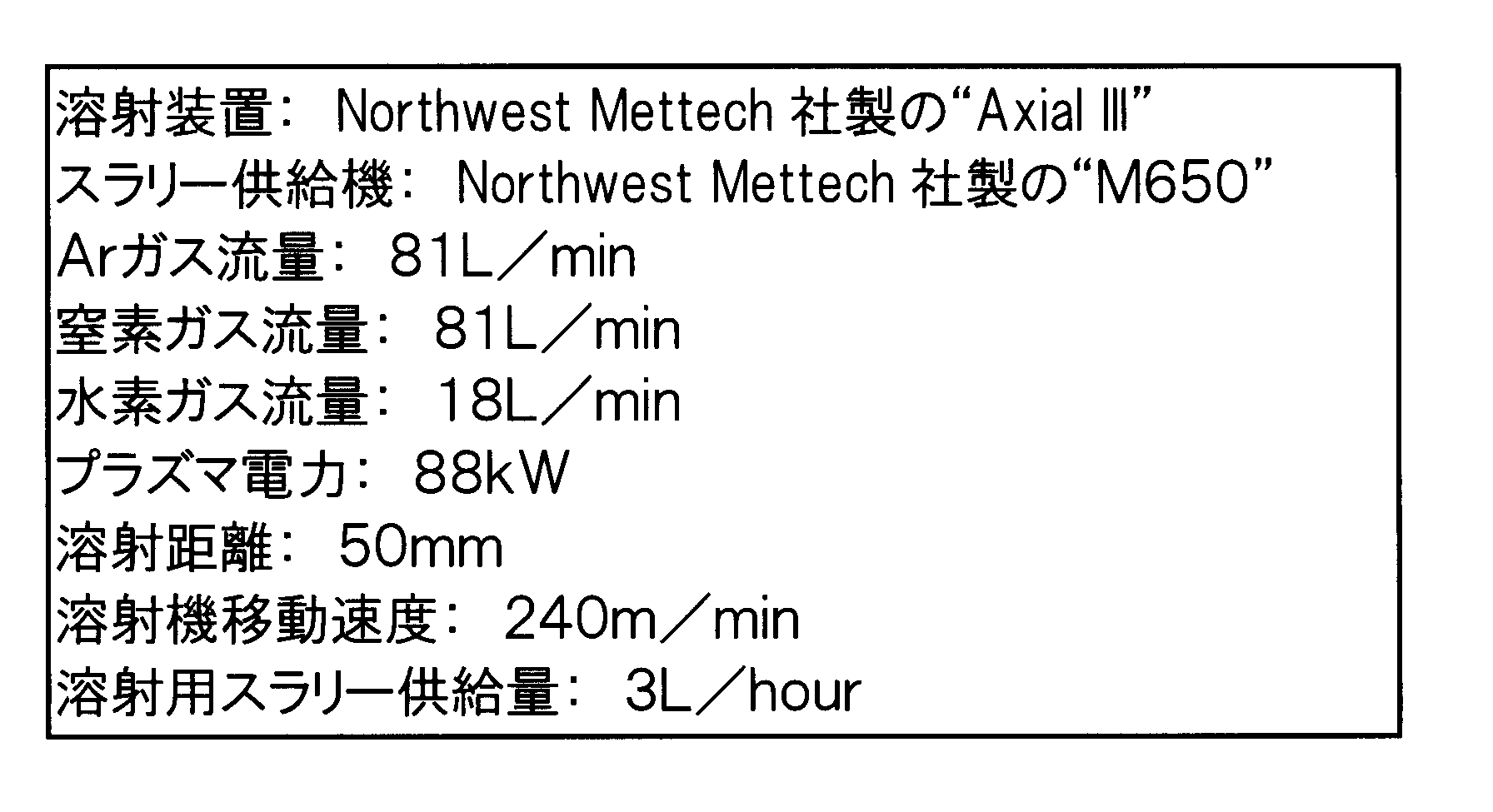
- Table 1 shows the result of evaluating the porosity of the thermal spray coating obtained by atmospheric pressure plasma spraying each slurry for thermal spraying under the conditions described in Table 2.
- the porosity was measured as follows. That is, after the cross section of the sprayed coating was resin-filled and polished, a cross-sectional image thereof was taken using a digital microscope VC-7700 manufactured by OMRON Corporation. And the pore part in a cross-sectional image was specified by the image analysis using image analysis software ImagePro made from Nippon Roper Co., Ltd., and the ratio of the area occupied in the cross-sectional image was obtained. “ ⁇ (good)” in the “Coating Properties No. 1” column indicates that the measured porosity of the sprayed coating was 10% or less, and “x (defect)” indicates that it was more than 10%. "-" Represents untested.
- Table 1 shows the results of evaluating the porosity of the thermal spray coating obtained by HVOF thermal spraying of each slurry for thermal spraying under the conditions shown in Table 3. “ ⁇ (good)” in the same column indicates that the porosity of the sprayed coating measured by the same method as described above was 10% or less, and “x (bad)” indicates that it was more than 10%. It represents that.
Landscapes
- Chemical & Material Sciences (AREA)
- Engineering & Computer Science (AREA)
- Organic Chemistry (AREA)
- Ceramic Engineering (AREA)
- Materials Engineering (AREA)
- Manufacturing & Machinery (AREA)
- Structural Engineering (AREA)
- Plasma & Fusion (AREA)
- Physics & Mathematics (AREA)
- Chemical Kinetics & Catalysis (AREA)
- Mechanical Engineering (AREA)
- Metallurgy (AREA)
- Composite Materials (AREA)
- Wood Science & Technology (AREA)
- Life Sciences & Earth Sciences (AREA)
- Inorganic Chemistry (AREA)
- Dispersion Chemistry (AREA)
- Health & Medical Sciences (AREA)
- Medicinal Chemistry (AREA)
- Polymers & Plastics (AREA)
- Coating By Spraying Or Casting (AREA)
- Application Of Or Painting With Fluid Materials (AREA)
Abstract
Description
溶射用スラリー中のセラミック粒子は、平均粒子径が200nm以上5μm以下と比較的大きいために、溶射用スラリー中で重力により容易に沈降して沈殿を生じる。ただし、1Lの容積を有する高さ16.5cmの円筒容器内に溶射用スラリーを700mL入れて室温下で一週間静置したときに生じる沈殿は、20℃以上30℃以下の温度下、中心軸が水平となるように円筒容器を置いてその中心軸周りで円筒容器を100rpmの回転速度で120分間にわたり回転させて円筒容器内の溶射用スラリーを撹拌することにより消失する。このような特定の条件下で沈殿を消失させることができれば、溶射用スラリーは十分に実用に値すると言える。
したがって、本実施形態によれば、セラミック粒子の沈降によって生じる沈殿が実用上十分な再分散性を示す溶射用スラリーが提供される。
前記実施形態は次のように変更されてもよい。
次に、実施例及び比較例を挙げて本発明をさらに具体的に説明する。


Claims (10)
- 200nm以上5μm以下の平均粒子径を有するセラミック粒子を含んだ溶射用スラリーであって、
1Lの容積を有する高さ16.5cmの円筒容器内に溶射用スラリーを700mL入れて室温下で一週間静置したときに生じる沈殿は、20℃以上30℃以下の温度下、中心軸が水平となるように円筒容器を置いてその中心軸周りで円筒容器を100rpmの回転速度で120分間にわたり回転させて円筒容器内の溶射用スラリーを撹拌することにより消失することを特徴とする溶射用スラリー。 - 凝集剤をさらに含有する請求項1記載の溶射用スラリー。
- 請求項1又は2に記載の溶射用スラリーを溶射して得られる溶射皮膜。
- 分散媒として水を含んだ請求項1又は2に記載の溶射用スラリーを高速フレーム溶射して溶射皮膜を形成する溶射皮膜の形成方法。
- 分散媒として有機溶剤を含んだ請求項1又は2に記載の溶射用スラリーをプラズマ溶射して溶射皮膜を形成する溶射皮膜の形成方法。
- 前記溶射用スラリーをアクシャルフィード方式で溶射装置に供給することを含む請求項4又は5に記載の溶射皮膜の形成方法。
- 前記溶射用スラリーを、2つのフィーダーを用いて、両フィーダーからの溶射用スラリーの供給量の変動周期が互いに逆位相となるようにして溶射装置に供給することを含む請求項4又は5に記載の溶射皮膜の形成方法。
- 前記溶射用スラリーをフィーダーから送り出して溶射装置の直前でタンクにいったん貯留し、自然落下を利用してそのタンク内の溶射用スラリーを溶射装置に供給することを含む請求項4又は5に記載の溶射皮膜の形成方法。
- 導電性チューブを介して溶射装置へ溶射用スラリーを供給することを含む請求項4又は5に記載の溶射皮膜の形成方法。
- 溶射時に前記溶射用スラリーがセラミック粒子の融点の110%以上の温度にまで加熱されることを含む請求項4~9のいずれか一項に記載の溶射皮膜の形成方法。
Priority Applications (3)
| Application Number | Priority Date | Filing Date | Title |
|---|---|---|---|
| JP2015505437A JP6159792B2 (ja) | 2013-03-13 | 2014-03-07 | 溶射用スラリー及び溶射皮膜の形成方法 |
| US14/773,863 US10377905B2 (en) | 2013-03-13 | 2014-03-07 | Slurry for thermal spraying, thermal sprayed coating, and method for forming thermal sprayed coating |
| KR1020157027727A KR101727848B1 (ko) | 2013-03-13 | 2014-03-07 | 용사용 슬러리, 용사 피막 및 용사 피막의 형성 방법 |
Applications Claiming Priority (2)
| Application Number | Priority Date | Filing Date | Title |
|---|---|---|---|
| JP2013050862 | 2013-03-13 | ||
| JP2013-050862 | 2013-03-13 |
Publications (1)
| Publication Number | Publication Date |
|---|---|
| WO2014142018A1 true WO2014142018A1 (ja) | 2014-09-18 |
Family
ID=51536679
Family Applications (1)
| Application Number | Title | Priority Date | Filing Date |
|---|---|---|---|
| PCT/JP2014/055935 Ceased WO2014142018A1 (ja) | 2013-03-13 | 2014-03-07 | 溶射用スラリー、溶射皮膜、及び溶射皮膜の形成方法 |
Country Status (5)
| Country | Link |
|---|---|
| US (1) | US10377905B2 (ja) |
| JP (1) | JP6159792B2 (ja) |
| KR (1) | KR101727848B1 (ja) |
| TW (1) | TWI615507B (ja) |
| WO (1) | WO2014142018A1 (ja) |
Cited By (6)
| Publication number | Priority date | Publication date | Assignee | Title |
|---|---|---|---|---|
| JP2016089241A (ja) * | 2014-11-08 | 2016-05-23 | リバストン工業株式会社 | 皮膜付き基材、その製造方法、その皮膜付き基材を含む半導体製造装置部材 |
| JP2017061734A (ja) * | 2015-09-25 | 2017-03-30 | 株式会社フジミインコーポレーテッド | 溶射用スラリー、溶射皮膜および溶射皮膜の形成方法 |
| JP2017078205A (ja) * | 2015-10-20 | 2017-04-27 | 株式会社フジミインコーポレーテッド | 溶射用スラリー、溶射皮膜および溶射皮膜の形成方法 |
| JP2020026579A (ja) * | 2018-08-10 | 2020-02-20 | 信越化学工業株式会社 | サスペンションプラズマ溶射用スラリー及び溶射皮膜の形成方法 |
| JP2020094287A (ja) * | 2015-10-20 | 2020-06-18 | 株式会社フジミインコーポレーテッド | 溶射用スラリー、溶射皮膜および溶射皮膜の形成方法 |
| US11066734B2 (en) | 2014-09-03 | 2021-07-20 | Fujimi Incorporated | Thermal spray slurry, thermal spray coating and method for forming thermal spray coating |
Families Citing this family (5)
| Publication number | Priority date | Publication date | Assignee | Title |
|---|---|---|---|---|
| KR20150123939A (ko) | 2013-03-13 | 2015-11-04 | 가부시키가이샤 후지미인코퍼레이티드 | 용사용 슬러리, 용사 피막 및 용사 피막의 형성 방법 |
| US10850298B1 (en) * | 2016-05-06 | 2020-12-01 | Madeline A. Kuchinski | System for non-contact coating of moving component through a falling flow of coating material |
| JP6859146B2 (ja) * | 2017-03-21 | 2021-04-14 | 株式会社フジミインコーポレーテッド | 溶射用スラリー |
| FR3081977A1 (fr) * | 2018-05-31 | 2019-12-06 | E.T.I.A. - Evaluation Technologique, Ingenierie Et Applications | Dispositif de traitement thermique a revetement rapporte, revetement et procede correspondants |
| CN114478035A (zh) * | 2022-01-17 | 2022-05-13 | 北京富创精密半导体有限公司 | 一种氧化钇及类似氧化物陶瓷材料悬浮液的处理方法 |
Citations (8)
| Publication number | Priority date | Publication date | Assignee | Title |
|---|---|---|---|---|
| JPH10298732A (ja) * | 1997-04-22 | 1998-11-10 | Sumitomo Metal Ind Ltd | 耐火物補修用溶射装置及び耐火物の溶射による補修法 |
| JP2004331852A (ja) * | 2003-05-09 | 2004-11-25 | Tama Kagaku Kogyo Kk | 分散安定性に優れた研磨剤スラリー及び基板の製造方法 |
| JP2006131997A (ja) * | 2004-10-29 | 2006-05-25 | United Technol Corp <Utc> | ワークピースの修復方法 |
| JP2009161789A (ja) * | 2007-12-28 | 2009-07-23 | Riverstone Kogyo Kk | セラミックス溶射皮膜とその製造法 |
| JP2010150617A (ja) * | 2008-12-25 | 2010-07-08 | Fujimi Inc | 溶射用スラリー、溶射皮膜の形成方法、及び溶射皮膜 |
| JP2010218759A (ja) * | 2009-03-13 | 2010-09-30 | Tokyo Electric Power Co Inc:The | 金属支持型固体酸化物形燃料電池及びその製造方法 |
| JP2011088037A (ja) * | 2009-10-20 | 2011-05-06 | Fujico Co Ltd | 溶射材料の製造方法及び溶射皮膜の製造方法 |
| JP2011524944A (ja) * | 2008-05-29 | 2011-09-08 | ノースウエスト メテック コーポレイション | 軸送りを用いて液体供給原料から皮膜を製造する方法および装置 |
Family Cites Families (41)
| Publication number | Priority date | Publication date | Assignee | Title |
|---|---|---|---|---|
| US4450184A (en) | 1982-02-16 | 1984-05-22 | Metco Incorporated | Hollow sphere ceramic particles for abradable coatings |
| JPS60149403A (ja) | 1984-01-13 | 1985-08-06 | イビデン株式会社 | セラミツク繊維成型体の製造方法 |
| US4741838A (en) * | 1985-06-12 | 1988-05-03 | Sharpe Andrew J Jr | Flocculation of high solids mineral slurries |
| US4755492A (en) * | 1986-10-06 | 1988-07-05 | General Electric Company | Yttrium oxide ceramic body |
| JPH0297459A (ja) * | 1988-10-04 | 1990-04-10 | Iwao Jiki Kogyo Kk | アルミナージルコニア焼結体の製造方法 |
| US5433901A (en) * | 1993-02-11 | 1995-07-18 | Vesuvius Crucible Company | Method of manufacturing an ITO sintered body |
| JP2988281B2 (ja) | 1994-10-05 | 1999-12-13 | 旭硝子株式会社 | 溶射用セラミックス・金属複合粉末及び溶射被膜の形成方法 |
| CN1195884C (zh) | 1995-11-13 | 2005-04-06 | 康涅狄格大学 | 用于热喷涂的纳米结构的进料 |
| JPH1088311A (ja) | 1996-09-17 | 1998-04-07 | Showa Denko Kk | タングステンカーバイド/コバルト溶射粉末及びその製造方法 |
| ATE226110T1 (de) * | 1998-08-04 | 2002-11-15 | Bp Oil Int | Delaminierter mikroporöser feststoff |
| US20060121068A1 (en) | 1999-08-31 | 2006-06-08 | General Electric Company | Boron nitride particles of spherical geometry and process for making thereof |
| US6294261B1 (en) | 1999-10-01 | 2001-09-25 | General Electric Company | Method for smoothing the surface of a protective coating |
| AU2001252636A1 (en) * | 2000-05-01 | 2001-11-12 | Tateho Chemical Industries Co., Ltd. | Magnesium oxide particle aggregate |
| JP3672833B2 (ja) | 2000-06-29 | 2005-07-20 | 信越化学工業株式会社 | 溶射粉及び溶射被膜 |
| AU2002226001A1 (en) | 2000-12-08 | 2002-06-18 | Sulzer Metco (Us) Inc. | Pre-alloyed stabilized zirconia powder and improved thermal barrier coating |
| EP1239055B1 (en) | 2001-03-08 | 2017-03-01 | Shin-Etsu Chemical Co., Ltd. | Thermal spray spherical particles, and sprayed components |
| KR20060043427A (ko) | 2004-03-05 | 2006-05-15 | 토소가부시키가이샤 | 원통형 스퍼터링 타겟, 세라믹 소결체와 그 제조방법 |
| US20070023402A1 (en) | 2005-07-26 | 2007-02-01 | United Technologies Corporation | Methods for repairing workpieces using microplasma spray coating |
| US7763823B2 (en) | 2004-10-29 | 2010-07-27 | United Technologies Corporation | Method and apparatus for microplasma spray coating a portion of a compressor blade in a gas turbine engine |
| US8367963B2 (en) | 2004-10-29 | 2013-02-05 | United Technologies Corporation | Method and apparatus for microplasma spray coating a portion of a turbine vane in a gas turbine engine |
| US20070087129A1 (en) | 2005-10-19 | 2007-04-19 | Blankenship Donn R | Methods for repairing a workpiece |
| US7115832B1 (en) | 2005-07-26 | 2006-10-03 | United Technologies Corporation | Microplasma spray coating apparatus |
| US8367967B2 (en) | 2004-10-29 | 2013-02-05 | United Technologies Corporation | Method and apparatus for repairing thermal barrier coatings |
| JP2006144094A (ja) | 2004-11-22 | 2006-06-08 | Fujimi Inc | 溶射用粉末及びその製造方法 |
| US7250080B1 (en) | 2006-09-06 | 2007-07-31 | Tronox Llc | Process for the manufacture of organosilicon compound-treated pigments |
| DE102008026101B4 (de) | 2008-05-30 | 2010-02-18 | Fraunhofer-Gesellschaft zur Förderung der angewandten Forschung e.V. | Thermisch gespritzte Al2O3-Schichten mit einem hohen Korundgehalt ohne eigenschaftsmindernde Zusätze und Verfahren zu ihrer Herstellung |
| CH701373A1 (de) | 2009-06-30 | 2010-12-31 | Alstom Technology Ltd | Schlickerformulierung zur Herstellung von thermischen Schutzschichten. |
| US20110086178A1 (en) * | 2009-10-14 | 2011-04-14 | General Electric Company | Ceramic coatings and methods of making the same |
| JP5479147B2 (ja) * | 2010-02-19 | 2014-04-23 | 株式会社トクヤマデンタル | 無機酸化物の製造方法 |
| US8524191B2 (en) * | 2011-08-08 | 2013-09-03 | Basf Se | Process for preparing high-purity aluminum oxide by purification of alumina |
| JP5396672B2 (ja) | 2012-06-27 | 2014-01-22 | 日本イットリウム株式会社 | 溶射材料及びその製造方法 |
| JP5990083B2 (ja) | 2012-10-19 | 2016-09-07 | 株式会社フジコー | 歯科医療機器の製造方法 |
| US20140178641A1 (en) | 2012-12-21 | 2014-06-26 | General Electric Company | Methods of coating a surface and articles with coated surface |
| KR20150123939A (ko) | 2013-03-13 | 2015-11-04 | 가부시키가이샤 후지미인코퍼레이티드 | 용사용 슬러리, 용사 피막 및 용사 피막의 형성 방법 |
| JP2014240511A (ja) | 2013-06-11 | 2014-12-25 | 株式会社フジミインコーポレーテッド | 溶射皮膜の製造方法および溶射用材料 |
| KR20150101447A (ko) | 2013-08-08 | 2015-09-03 | 닛폰 이트륨 가부시키가이샤 | 용사용 슬러리 |
| US10730798B2 (en) * | 2014-05-07 | 2020-08-04 | Applied Materials, Inc. | Slurry plasma spray of plasma resistant ceramic coating |
| US20170113972A1 (en) | 2014-06-04 | 2017-04-27 | Imerys Ceramics France | Ceramic compositions |
| CN106605008B (zh) | 2014-09-03 | 2019-08-27 | 福吉米株式会社 | 喷镀用浆料、喷镀皮膜及喷镀皮膜的形成方法 |
| JP6513794B2 (ja) | 2014-09-18 | 2019-05-15 | エリコン メテコ(ユーエス)インコーポレイテッド | 予備配合された粉末原料 |
| JP6741410B2 (ja) | 2015-09-25 | 2020-08-19 | 株式会社フジミインコーポレーテッド | 溶射用スラリー、溶射皮膜および溶射皮膜の形成方法 |
-
2014
- 2014-03-07 US US14/773,863 patent/US10377905B2/en active Active
- 2014-03-07 WO PCT/JP2014/055935 patent/WO2014142018A1/ja not_active Ceased
- 2014-03-07 JP JP2015505437A patent/JP6159792B2/ja active Active
- 2014-03-07 KR KR1020157027727A patent/KR101727848B1/ko active Active
- 2014-03-11 TW TW103108411A patent/TWI615507B/zh active
Patent Citations (8)
| Publication number | Priority date | Publication date | Assignee | Title |
|---|---|---|---|---|
| JPH10298732A (ja) * | 1997-04-22 | 1998-11-10 | Sumitomo Metal Ind Ltd | 耐火物補修用溶射装置及び耐火物の溶射による補修法 |
| JP2004331852A (ja) * | 2003-05-09 | 2004-11-25 | Tama Kagaku Kogyo Kk | 分散安定性に優れた研磨剤スラリー及び基板の製造方法 |
| JP2006131997A (ja) * | 2004-10-29 | 2006-05-25 | United Technol Corp <Utc> | ワークピースの修復方法 |
| JP2009161789A (ja) * | 2007-12-28 | 2009-07-23 | Riverstone Kogyo Kk | セラミックス溶射皮膜とその製造法 |
| JP2011524944A (ja) * | 2008-05-29 | 2011-09-08 | ノースウエスト メテック コーポレイション | 軸送りを用いて液体供給原料から皮膜を製造する方法および装置 |
| JP2010150617A (ja) * | 2008-12-25 | 2010-07-08 | Fujimi Inc | 溶射用スラリー、溶射皮膜の形成方法、及び溶射皮膜 |
| JP2010218759A (ja) * | 2009-03-13 | 2010-09-30 | Tokyo Electric Power Co Inc:The | 金属支持型固体酸化物形燃料電池及びその製造方法 |
| JP2011088037A (ja) * | 2009-10-20 | 2011-05-06 | Fujico Co Ltd | 溶射材料の製造方法及び溶射皮膜の製造方法 |
Cited By (8)
| Publication number | Priority date | Publication date | Assignee | Title |
|---|---|---|---|---|
| US11066734B2 (en) | 2014-09-03 | 2021-07-20 | Fujimi Incorporated | Thermal spray slurry, thermal spray coating and method for forming thermal spray coating |
| JP2016089241A (ja) * | 2014-11-08 | 2016-05-23 | リバストン工業株式会社 | 皮膜付き基材、その製造方法、その皮膜付き基材を含む半導体製造装置部材 |
| JP2017061734A (ja) * | 2015-09-25 | 2017-03-30 | 株式会社フジミインコーポレーテッド | 溶射用スラリー、溶射皮膜および溶射皮膜の形成方法 |
| US10196729B2 (en) | 2015-09-25 | 2019-02-05 | Fujimi Incorporated | Slurry for thermal spraying, sprayed coating, and method for forming sprayed coating |
| JP2017078205A (ja) * | 2015-10-20 | 2017-04-27 | 株式会社フジミインコーポレーテッド | 溶射用スラリー、溶射皮膜および溶射皮膜の形成方法 |
| JP2020094287A (ja) * | 2015-10-20 | 2020-06-18 | 株式会社フジミインコーポレーテッド | 溶射用スラリー、溶射皮膜および溶射皮膜の形成方法 |
| JP2020026579A (ja) * | 2018-08-10 | 2020-02-20 | 信越化学工業株式会社 | サスペンションプラズマ溶射用スラリー及び溶射皮膜の形成方法 |
| JP7156203B2 (ja) | 2018-08-10 | 2022-10-19 | 信越化学工業株式会社 | サスペンションプラズマ溶射用スラリー及び溶射皮膜の形成方法 |
Also Published As
| Publication number | Publication date |
|---|---|
| US10377905B2 (en) | 2019-08-13 |
| JP6159792B2 (ja) | 2017-07-05 |
| US20160040278A1 (en) | 2016-02-11 |
| KR20150123940A (ko) | 2015-11-04 |
| KR101727848B1 (ko) | 2017-04-17 |
| JPWO2014142018A1 (ja) | 2017-02-16 |
| TW201506202A (zh) | 2015-02-16 |
| TWI615507B (zh) | 2018-02-21 |
Similar Documents
| Publication | Publication Date | Title |
|---|---|---|
| JP6185047B2 (ja) | 溶射用スラリー、及び溶射皮膜の形成方法 | |
| JP6159792B2 (ja) | 溶射用スラリー及び溶射皮膜の形成方法 | |
| JP6262716B2 (ja) | 溶射用粉末、及び溶射皮膜の形成方法 | |
| KR102481729B1 (ko) | 용사용 슬러리, 용사 피막 및 용사 피막의 형성 방법 | |
| JP6291069B2 (ja) | 溶射用スラリー、溶射皮膜および溶射皮膜の形成方法 | |
| KR20170037514A (ko) | 용사용 슬러리 | |
| JP2020056114A (ja) | 溶射用スラリー | |
| WO2019188763A1 (ja) | 溶射用スラリー | |
| JP2025059871A (ja) | 溶射用スラリーおよびこれを用いた溶射皮膜の製造方法 | |
| JP2018154894A (ja) | 溶射用スラリー |
Legal Events
| Date | Code | Title | Description |
|---|---|---|---|
| 121 | Ep: the epo has been informed by wipo that ep was designated in this application |
Ref document number: 14762503 Country of ref document: EP Kind code of ref document: A1 |
|
| ENP | Entry into the national phase |
Ref document number: 2015505437 Country of ref document: JP Kind code of ref document: A |
|
| WWE | Wipo information: entry into national phase |
Ref document number: 14773863 Country of ref document: US |
|
| NENP | Non-entry into the national phase |
Ref country code: DE |
|
| ENP | Entry into the national phase |
Ref document number: 20157027727 Country of ref document: KR Kind code of ref document: A |
|
| 122 | Ep: pct application non-entry in european phase |
Ref document number: 14762503 Country of ref document: EP Kind code of ref document: A1 |