WO2014136799A1 - 二次電池セパレーターの多孔膜用スラリー、二次電池セパレーター用多孔膜及びその製造方法、二次電池用セパレーター並びに二次電池 - Google Patents
二次電池セパレーターの多孔膜用スラリー、二次電池セパレーター用多孔膜及びその製造方法、二次電池用セパレーター並びに二次電池 Download PDFInfo
- Publication number
- WO2014136799A1 WO2014136799A1 PCT/JP2014/055516 JP2014055516W WO2014136799A1 WO 2014136799 A1 WO2014136799 A1 WO 2014136799A1 JP 2014055516 W JP2014055516 W JP 2014055516W WO 2014136799 A1 WO2014136799 A1 WO 2014136799A1
- Authority
- WO
- WIPO (PCT)
- Prior art keywords
- secondary battery
- particles
- water
- porous membrane
- separator
- Prior art date
Links
Images


Classifications
-
- H—ELECTRICITY
- H01—ELECTRIC ELEMENTS
- H01M—PROCESSES OR MEANS, e.g. BATTERIES, FOR THE DIRECT CONVERSION OF CHEMICAL ENERGY INTO ELECTRICAL ENERGY
- H01M50/00—Constructional details or processes of manufacture of the non-active parts of electrochemical cells other than fuel cells, e.g. hybrid cells
- H01M50/40—Separators; Membranes; Diaphragms; Spacing elements inside cells
- H01M50/409—Separators, membranes or diaphragms characterised by the material
- H01M50/449—Separators, membranes or diaphragms characterised by the material having a layered structure
-
- H—ELECTRICITY
- H01—ELECTRIC ELEMENTS
- H01M—PROCESSES OR MEANS, e.g. BATTERIES, FOR THE DIRECT CONVERSION OF CHEMICAL ENERGY INTO ELECTRICAL ENERGY
- H01M50/00—Constructional details or processes of manufacture of the non-active parts of electrochemical cells other than fuel cells, e.g. hybrid cells
- H01M50/40—Separators; Membranes; Diaphragms; Spacing elements inside cells
- H01M50/403—Manufacturing processes of separators, membranes or diaphragms
-
- Y—GENERAL TAGGING OF NEW TECHNOLOGICAL DEVELOPMENTS; GENERAL TAGGING OF CROSS-SECTIONAL TECHNOLOGIES SPANNING OVER SEVERAL SECTIONS OF THE IPC; TECHNICAL SUBJECTS COVERED BY FORMER USPC CROSS-REFERENCE ART COLLECTIONS [XRACs] AND DIGESTS
- Y02—TECHNOLOGIES OR APPLICATIONS FOR MITIGATION OR ADAPTATION AGAINST CLIMATE CHANGE
- Y02E—REDUCTION OF GREENHOUSE GAS [GHG] EMISSIONS, RELATED TO ENERGY GENERATION, TRANSMISSION OR DISTRIBUTION
- Y02E60/00—Enabling technologies; Technologies with a potential or indirect contribution to GHG emissions mitigation
- Y02E60/10—Energy storage using batteries
Definitions
- the present invention relates to a slurry for a porous film of a secondary battery separator, a porous film for a secondary battery separator and a method for producing the same, a separator for a secondary battery, and a secondary battery.
- a separator In secondary batteries, a separator is generally used to prevent a short circuit between the positive electrode and the negative electrode.
- the separator may affect the performance of the secondary battery such as safety and battery characteristics. For this reason, various studies have been made on separators (see Patent Documents 1 to 4).
- JP 2007-294437 A Japanese Patent Laid-Open No. 2005-056800 JP 2006-182925 A International Publication No. 2011/040562
- the separator usually has an organic separator layer.
- a porous film may be provided on the organic separator layer as necessary.
- the present invention was devised in view of the above-mentioned problems, and is a secondary battery that is excellent in safety, high-temperature cycle characteristics, and rate characteristics; such safety, high-temperature cycle characteristics, and rate characteristics are all excellent.
- An object of the present invention is to provide a slurry for a porous membrane of a secondary battery separator capable of realizing a secondary battery, a porous membrane for a secondary battery separator and a separator for a secondary battery; and a method for producing the porous membrane for a secondary battery separator.
- the present inventor is a slurry for a porous film containing insulating particles having non-conductive particles, a particulate binder, a water-soluble binder and a medium, and a predetermined proportion of insulating particles.
- Insulating particles having non-conductive particles, a particulate binder, a water-soluble binder and a medium, 15% to 85% by volume of the insulating particles have a water-insoluble polymer that covers the surface of the non-conductive particles and occupies 70% or more of the surface of the insulating particles;
- a porous membrane for a secondary battery separator comprising insulating particles having non-conductive particles, a particulate binder and a water-soluble binder, 15% to 85% by volume of the insulating particles have a water-insoluble polymer that covers the surface of the non-conductive particles and occupies 70% or more of the surface of the insulating particles;
- a porous membrane for a secondary battery separator wherein the swelling degree of the water-insoluble polymer with respect to the non-aqueous electrolyte is 10 to 50 times.
- [6] A method for producing a porous membrane for a secondary battery separator according to [5], Applying the slurry for porous membrane according to any one of [1] to [4] on a substrate to obtain a slurry layer; and The manufacturing method of the porous film for secondary battery separators including drying the said slurry layer.
- a secondary battery comprising a positive electrode, a negative electrode, the separator for secondary batteries according to [7], and a non-aqueous electrolyte.
- a porous membrane for a secondary battery separator capable of realizing a secondary battery excellent in all of safety, high temperature cycle characteristics, and rate characteristics can be obtained.
- a secondary battery excellent in safety, high temperature cycle characteristics and rate characteristics can be obtained.
- a porous membrane for a secondary battery separator capable of realizing a secondary battery excellent in all of safety, high temperature cycle characteristics and rate characteristics can be obtained.
- a secondary battery excellent in all of safety, high temperature cycle characteristics and rate characteristics can be obtained.
- the secondary battery of the present invention is excellent in all of safety, high-temperature cycle characteristics, and rate characteristics.
- FIG. 1 is an enlarged cross-sectional view schematically showing the vicinity of the surface of a porous membrane that is not wetted with a non-aqueous electrolyte.
- FIG. 2 is an enlarged cross-sectional view schematically showing the vicinity of the surface of the porous membrane wet with the nonaqueous electrolytic solution.
- (meth) acrylic acid represents acrylic acid or methacrylic acid.
- (meth) acrylate represents an acrylate or a methacrylate.
- (meth) acrylonitrile represents acrylonitrile or methacrylonitrile.
- a certain substance (this substance contains a polymer) is water-soluble.
- the insoluble content is less than 1% by weight. It means that.
- a certain substance is water-insoluble means that an insoluble content is 90% by weight or more when 0.5 g of the substance is dissolved in 100 g of water at 25 ° C.
- the proportion of the structural unit formed by polymerizing a certain monomer in the polymer is usually that unless otherwise specified. This coincides with the ratio (preparation ratio) of the certain monomer in the total monomers used for polymerization of the polymer.
- the slurry for the porous membrane of the secondary battery separator of the present invention (hereinafter sometimes referred to as “slurry for porous membrane” as appropriate) includes insulating particles having non-conductive particles, a particulate binder, a water-soluble binder, and a medium. It is a fluid composition.
- Insulating particles are particles having non-conductive particles.
- the insulating particles are non-conductive particles whose surfaces are covered with a water-insoluble polymer; or a mixture of non-conductive particles themselves and non-conductive particles whose surfaces are covered with a water-insoluble polymer. is there.
- the insulating particles are specific insulating particles (non-conductive particles whose surface is covered with 70% or more of a water-insoluble polymer (this specific insulating particle is referred to as “coated particles (A ) ”)) Is included at 15 volume% to 85 volume%. That is, 15 to 85% by volume of the insulating particles are non-conductive particles in which 70% or more of the surface is covered with a water-insoluble polymer.
- the insulating particles include (i) coated particles (A) having non-conductive particles and a water-insoluble polymer that covers the surface of the non-conductive particles and occupies 70% or more of the surface of the insulating particles. It is included at a predetermined rate.
- the insulating particles other than the coated particles (A) are (ii) non-conductive particles themselves not coated with a water-insoluble polymer, or non-conductive particles and non-conductive particles thereof. Insulating particles having a water-insoluble polymer that covers less than 70% of the surface of the insulating particles (such as insulating particles other than the covering particles (A) are hereinafter referred to as “bare”. Particles (B) ”).
- FIG. 1 is an enlarged cross-sectional view schematically showing the vicinity of the surface of a porous membrane that is not wetted with a non-aqueous electrolyte.
- the coated particles (A) 10 include non-conductive particles 11 and a water-insoluble polymer 12 that covers the surface 11S of the non-conductive particles 11.
- non-conductive particles inorganic particles or organic particles may be used.
- the inorganic particles are usually excellent in dispersion stability in the medium, hardly settled in the slurry for the porous membrane, and can maintain a uniform slurry state for a long time. Further, when inorganic particles are used, the heat resistance of a porous membrane for a secondary battery separator (hereinafter sometimes referred to as “porous membrane”) can be increased.
- an electrochemically stable material is preferable.
- inorganic materials for non-conductive particles include aluminum oxide (alumina), aluminum oxide hydrate (boehmite (AlOOH)), gibbsite (Al (OH) 3 ), silicon oxide.
- Oxide particles such as magnesium oxide (magnesia), magnesium hydroxide, calcium oxide, titanium oxide (titania), BaTiO 3 , ZrO, alumina-silica composite oxide; nitride particles such as aluminum nitride and boron nitride; silicon, Examples include covalently bonded crystal particles such as diamond; sparingly soluble ionic crystal particles such as barium sulfate, calcium fluoride, and barium fluoride; clay fine particles such as talc and montmorillonite.
- oxide particles are preferable.
- titanium oxide from the viewpoint of low water absorption and excellent heat resistance (for example, resistance to high temperature of 180 ° C. or higher), Aluminum oxide, aluminum oxide hydrate, magnesium oxide and magnesium hydroxide are more preferred, aluminum oxide, aluminum oxide hydrate, magnesium oxide and magnesium hydroxide are more preferred, and aluminum oxide is particularly preferred.
- Polymer particles are usually used as the organic particles.
- the organic particles can control the affinity for water by adjusting the type and amount of the functional group on the surface of the organic particles, and thus can control the amount of water contained in the porous film.
- Organic particles are excellent in that they usually have less metal ion elution.
- the organic material for the nonconductive particles include various polymer compounds such as polystyrene, polyethylene, polyimide, melamine resin, and phenol resin.
- the polymer compound forming the particles may be used, for example, as a mixture, a modified product, a derivative, a random copolymer, an alternating copolymer, a graft copolymer, a block copolymer, a crosslinked product, or the like.
- the organic particles may be formed of a mixture of two or more polymer compounds.
- the glass transition temperature may not be present, but when the polymer compound forming the organic particles has a glass transition temperature, the glass transition temperature is usually 150 ° C. or higher. Preferably it is 200 degreeC or more, More preferably, it is 250 degreeC or more, and is 500 degrees C or less normally.
- Non-conductive particles may be subjected to, for example, element substitution, surface treatment, solid solution, and the like as necessary. Further, the non-conductive particles may include one kind of the above materials alone in one particle, or may contain two or more kinds in combination at an arbitrary ratio. . Further, the non-conductive particles may be used in combination of two or more kinds of particles formed of different materials.
- the surface treatment includes, for example, a treatment in which the non-conductive particles and the functional silane coupling agent are stirred at room temperature or under heating conditions as necessary.
- the binding property between the surface of the non-conductive particles and the water-insoluble polymer can be improved.
- the functional silane coupling agent include, for example, trimethoxysilylbenzoic acid, ⁇ -methacryloxypropyltrimethoxysilane, vinyltriacetoxysilane, vinyltrimethoxysilane, ⁇ -isocyanatopropyltriethoxysilane, ⁇ -glycol.
- Sidoxypropyltrimethoxysilane, ⁇ - (3,4-epoxycyclohexyl) ethyltrimethoxysilane and the like can be mentioned.
- ⁇ -glycidoxypropyltrimethoxysilane and ⁇ - (3,4-epoxycyclohexyl) ethyltrimethoxysilane can be preferably used.
- a functional silane coupling agent may be used individually by 1 type, and may be used combining two or more types by arbitrary ratios.
- Examples of the shape of the nonconductive particles include a spherical shape, an elliptical spherical shape, a polygonal shape, a tetrapod (registered trademark) shape, a plate shape, and a scale shape.
- the tetrapod (registered trademark) shape, plate And scaly are preferred.
- the number average particle diameter of the non-conductive particles is preferably 100 nm or more, more preferably 150 nm or more, particularly preferably 200 nm or more, preferably 2000 nm or less, more preferably 1500 nm or less, and particularly preferably 1000 nm or less.
- the number average particle size is a particle size-number cumulative distribution measured using a laser diffraction / scattering particle size distribution analyzer (for example, “LS230” manufactured by Beckman Coulter, Inc.). Is the particle diameter.
- the degree of swelling of the water-insoluble polymer dried at 50 ° C. for 10 minutes and further dried at 105 ° C. for 3 hours with respect to the non-aqueous electrolyte falls within a predetermined range.
- the specific range of the degree of swelling is usually 10 times or more, preferably 11 times or more, more preferably 12 times or more, and usually 50 times or less, preferably 35 times or less, more preferably 20 times or less.
- the degree of swelling of a water-insoluble polymer that has been dried at 50 ° C. for 10 minutes and further dried at 105 ° C. for 3 hours with respect to the non-aqueous electrolyte is determined by the amount of water-insoluble contained in the porous film formed using the porous film slurry.
- the swelling degree of the conductive polymer with respect to the non-aqueous electrolyte is the same.
- the degree of swelling above the lower limit of the above range, the ion permeability of the porous membrane can be increased and the resistance can be reduced. Therefore, the rate characteristic and high temperature cycle characteristic of the secondary battery can be improved.
- the binding property of a water-insoluble polymer can be improved by setting it as an upper limit or less, the binding property of a porous film and an electrode can be improved. Therefore, the cycle characteristics of the secondary battery can be improved.
- the degree of swelling of the water-insoluble polymer dried at 50 ° C. for 10 minutes and further dried at 105 ° C. for 3 hours with respect to the non-aqueous electrolyte can be measured by the following method.
- the aqueous dispersion of the coated particles (A) is poured into a silicon container so as to have a dry thickness of 1 mm and dried to obtain a dried product.
- the drying at this time is performed under the drying conditions of drying at 50 ° C. for 10 minutes and further drying at 105 ° C. for 3 hours.
- This drying condition is usually a drying condition for obtaining a water-insoluble polymer similar to that contained in the porous membrane.
- the dried body is pulverized to a size of about 0.1 mm square.
- the pulverized dried product is dispersed in an epoxy resin, and the epoxy resin is cured to obtain a cured resin product.
- the cured resin is cooled to ⁇ 80 ° C. and then cut with a microtome to produce a thin film.
- This thin film is observed with a field emission electron microscope (FE-TEM).
- FE-TEM field emission electron microscope
- 200 coated particles (A) are arbitrarily selected.
- the coverage with the water-insoluble polymer refers to the ratio of the area of the portion of the coated particle (A) occupied by the water-insoluble polymer to the area of the coated particle (A) in the observed image. Then, the area of the portion of each of the selected coated particles (A) occupied by the water-insoluble polymer of the coated particles (A) is measured.
- the average value of the area occupied by the water-insoluble polymer of the selected coated particle (A) is defined as area E0.
- an aqueous dispersion of the coated particles (A) is poured into a silicon container so as to have a dry thickness of 1 mm and dried to obtain a dried product. The drying at this time is performed under the drying conditions of drying at 50 ° C. for 10 minutes and further drying at 105 ° C. for 3 hours.
- This dried body is immersed in a nonaqueous electrolytic solution at 60 ° C. for 72 hours, and freeze-dried after the immersion.
- the dried product thus freeze-dried is pulverized to a size of about 0.1 mm square.
- the pulverized dry body is dispersed in an epoxy resin, and the epoxy resin is cured to obtain a cured resin body.
- the cured resin is cooled to ⁇ 80 ° C. and then cut with a microtome to produce a thin film.
- This thin film is observed with a field emission electron microscope (FE-TEM).
- 200 coated particles (A) are arbitrarily selected.
- the area of the portion of each of the selected coated particles (A) occupied by the water-insoluble polymer of the coated particles (A) is measured.
- An average value of the area occupied by the water-insoluble polymer of the selected coated particle (A) is defined as area E1.
- the swelling degree S of a water-insoluble polymer is computed with the following formula
- S ((E1) 1/2 ) 3 / ((E0) 1/2 ) 3
- the non-aqueous electrolyte is obtained by adding 2% by volume of vinylene carbonate (VC) to a LiPF 6 solution having a concentration of 1.0 M.
- VC vinylene carbonate
- the water-insoluble polymer As a means for making the water-insoluble polymer have the above-mentioned swelling degree, for example, the kind of the monomer of the water-insoluble polymer, the crosslinking degree and the molecular weight of the water-insoluble polymer, etc. are appropriately set. Adjusting.
- Such a water-insoluble polymer is water-insoluble, and the degree of swelling with respect to the non-aqueous electrolytic solution when dried at 50 ° C. for 10 minutes and further dried at 105 ° C. for 3 hours falls within the above range. As long as it is arbitrary. Moreover, a water-insoluble polymer may be used individually by 1 type, and may be used combining two or more types by arbitrary ratios.
- Preferred examples of the water-insoluble polymer include styrene / butadiene copolymer (SBR), acrylonitrile / butadiene copolymer (NBR), hydrogenated SBR, hydrogenated NBR, and styrene / isoprene / styrene block copolymer. (SIS), an acrylic polymer, etc. are mentioned. Among these, acrylic polymers are more preferable because they can be used in any porous film on the positive electrode side and the negative electrode side and are excellent in versatility.
- the acrylic polymer is a polymer containing a (meth) acrylic acid ester monomer unit.
- the (meth) acrylic acid ester monomer unit represents a structural unit having a structure formed by polymerizing a (meth) acrylic acid ester monomer.
- Examples of the (meth) acrylic acid ester monomer include a compound represented by CH 2 ⁇ CR a —COOR b .
- R a represents a hydrogen atom or a methyl group
- R b represents an alkyl group or a cycloalkyl group.
- Examples of (meth) acrylate monomers include methyl acrylate, ethyl acrylate, n-propyl acrylate, isopropyl acrylate, n-butyl acrylate, isobutyl acrylate, t-butyl acrylate, acrylic N-amyl acid, isoamyl acrylate, n-hexyl acrylate, 2-ethylhexyl acrylate, 2-methoxyethyl acrylate, 2-ethoxyethyl acrylate, hexyl acrylate, nonyl acrylate, lauryl acrylate, acrylic Acrylates such as stearyl acid and benzyl acrylate; methyl methacrylate, ethyl methacrylate, propyl methacrylate, isopropyl methacrylate, n-butyl methacrylate, isobutyl methacrylate, t-butyl methacrylate, n-a
- acrylate is preferable, and n-butyl acrylate and 2-ethylhexyl acrylate are particularly preferable in that the strength of the porous film can be improved. Moreover, these may be used individually by 1 type and may be used combining two or more types by arbitrary ratios.
- the proportion of (meth) acrylic acid ester monomer units in the acrylic polymer is preferably 20.0% by weight or more, more preferably 30.0% by weight or more, particularly preferably 40.0% by weight or more, preferably Is 80.0% by weight or less, more preferably 70.0% by weight or less, and particularly preferably 60.0% by weight or less.
- the acrylic polymer may contain a (meth) acrylonitrile monomer unit.
- the (meth) acrylonitrile monomer unit represents a structural unit having a structure formed by polymerizing (meth) acrylonitrile. Since an acrylic polymer containing a combination of a (meth) acrylonitrile monomer unit and a (meth) acrylic acid ester monomer unit is stable to oxidation and reduction, it is easy to obtain a long-life battery.
- the acrylic polymer may contain only a structural unit having a structure formed by polymerizing acrylonitrile as a (meth) acrylonitrile monomer unit, or a structure having a structure formed by polymerizing methacrylonitrile. It may contain only units, and it contains a combination of both a structural unit having a structure formed by polymerizing acrylonitrile and a structural unit having a structure formed by polymerizing methacrylonitrile in any ratio. Also good.
- the proportion of the (meth) acrylonitrile monomer unit in the acrylic polymer is preferably 5.0% by weight or more, more preferably 10.0% by weight or more, particularly preferably 15.0% by weight or more, preferably 55%. 0.0% by weight or less, more preferably 50.0% by weight or less, and particularly preferably 40.0% by weight or less.
- the acrylic polymer can contain an ethylenically unsaturated carboxylic acid monomer unit.
- the ethylenically unsaturated carboxylic acid monomer unit represents a structural unit having a structure formed by polymerizing an ethylenically unsaturated carboxylic acid monomer.
- Examples of the ethylenically unsaturated carboxylic acid monomer include ethylenically unsaturated monocarboxylic acid and derivatives thereof, ethylenically unsaturated dicarboxylic acid and acid anhydrides thereof, and derivatives thereof.
- Examples of the ethylenically unsaturated monocarboxylic acid include acrylic acid, methacrylic acid, crotonic acid and the like.
- Examples of derivatives of ethylenically unsaturated monocarboxylic acids include 2-ethylacrylic acid, isocrotonic acid, ⁇ -acetoxyacrylic acid, ⁇ -trans-aryloxyacrylic acid, ⁇ -chloro- ⁇ -E-methoxyacrylic acid, Examples thereof include ⁇ -diaminoacrylic acid.
- Examples of the ethylenically unsaturated dicarboxylic acid include maleic acid, fumaric acid, itaconic acid and the like.
- Examples of the acid anhydride of the ethylenically unsaturated dicarboxylic acid include maleic anhydride, acrylic anhydride, methyl maleic anhydride, dimethyl maleic anhydride and the like.
- Examples of ethylenically unsaturated dicarboxylic acid derivatives include maleic acid having substituents such as methylmaleic acid, dimethylmaleic acid, phenylmaleic acid, chloromaleic acid, dichloromaleic acid, fluoromaleic acid; Examples thereof include maleyl esters such as acid nonyl, decyl maleate, dodecyl maleate, octadecyl maleate and fluoroalkyl maleate.
- ethylenically unsaturated monocarboxylic acids such as acrylic acid and methacrylic acid are preferable from the viewpoint of enhancing the dispersibility of the coated particles (A) in water.
- One of these may be used alone, or two or more of these may be used in combination at any ratio.
- the ratio of the ethylenically unsaturated carboxylic acid monomer unit in the acrylic polymer is preferably 0.2% by weight or more, more preferably 0.4% by weight or more, particularly preferably 0.6% by weight or more, preferably Is 10.0% by weight or less, more preferably 6.0% by weight or less, and particularly preferably 4.0% by weight or less.
- the acrylic polymer can contain a crosslinkable monomer unit.
- the crosslinkable monomer unit represents a structural unit having a structure formed by polymerizing a crosslinkable monomer.
- a crosslinkable monomer represents the monomer which can form a crosslinked structure during superposition
- a monomer having heat crosslinkability is usually mentioned. More specifically, a monofunctional monomer having a thermally crosslinkable crosslinkable group and one olefinic double bond per molecule; a multifunctional having two or more olefinic double bonds per molecule Monomer.
- crosslinkable group examples include an epoxy group, an N-methylolamide group, an oxetanyl group, an oxazoline group, and an allyl group.
- One kind of these crosslinkable groups may be used, or two or more kinds may be used in any combination.
- an epoxy group and an allyl group are preferable because the crosslinking and the crosslinking density can be easily adjusted.
- crosslinkable monomer having an epoxy group as a thermally crosslinkable group and having an olefinic double bond examples include vinyl glycidyl ether, allyl glycidyl ether, butenyl glycidyl ether, o-allylphenyl glycidyl.
- Unsaturated glycidyl ethers such as ether; butadiene monoepoxide, chloroprene monoepoxide, 4,5-epoxy-2-pentene, 3,4-epoxy-1-vinylcyclohexene, 1,2-epoxy-5,9-cyclododecadiene Monoepoxides of dienes or polyenes such as; alkenyl epoxides such as 3,4-epoxy-1-butene, 1,2-epoxy-5-hexene, 1,2-epoxy-9-decene; and glycidyl acrylate, glycidyl methacrylate, Glycidyl crotonate, Unsaturated carboxylic acids such as glycidyl-4-heptenoate, glycidyl sorbate, glycidyl linoleate, glycidyl-4-methyl-3-pentenoate, glycidyl este
- crosslinkable monomer having an allyl group as a thermally crosslinkable group and having an olefinic double bond examples include allyl acrylate and allyl methacrylate.
- crosslinkable monomer having an N-methylolamide group as a thermally crosslinkable group and having an olefinic double bond have a methylol group such as N-methylol (meth) acrylamide (meta ) Acrylamides.
- crosslinkable monomer having an oxetanyl group as a thermally crosslinkable group and having an olefinic double bond examples include 3-((meth) acryloyloxymethyl) oxetane, 3-((meth) Acryloyloxymethyl) -2-trifluoromethyloxetane, 3-((meth) acryloyloxymethyl) -2-phenyloxetane, 2-((meth) acryloyloxymethyl) oxetane, and 2-((meth) acryloyloxymethyl) ) -4-Trifluoromethyloxetane.
- crosslinkable monomer having an oxazoline group as a heat crosslinkable group and having an olefinic double bond examples include 2-vinyl-2-oxazoline, 2-vinyl-4-methyl-2- Oxazoline, 2-vinyl-5-methyl-2-oxazoline, 2-isopropenyl-2-oxazoline, 2-isopropenyl-4-methyl-2-oxazoline, 2-isopropenyl-5-methyl-2-oxazoline, and 2-isopropenyl-5-ethyl-2-oxazoline.
- crosslinkable monomers having two or more olefinic double bonds per molecule examples include allyl (meth) acrylate, ethylene di (meth) acrylate, diethylene glycol di (meth) acrylate, and triethylene glycol di (meth).
- ethylene dimethacrylate, allyl glycidyl ether, and glycidyl methacrylate are particularly preferable as the crosslinkable monomer. Moreover, these may be used individually by 1 type and may be used combining two or more types by arbitrary ratios.
- the ratio of the crosslinkable monomer unit in the acrylic polymer is preferably 0.10% by weight or more, more preferably 0.20% by weight or more, particularly preferably 0.50% by weight or more, preferably 20.0%. % By weight or less, more preferably 15.0% by weight or less, particularly preferably 10.0% by weight or less. Since the strength of the water-insoluble polymer in the non-aqueous electrolyte can be increased by setting the ratio of the crosslinkable monomer unit to the lower limit of the above range, the binding force between the electrode and the porous membrane can be increased. Can be increased. Moreover, by being below an upper limit, a crosslinking density can be controlled low and ion permeability can be ensured.
- the acrylic polymer may contain an arbitrary structural unit other than the structural units described above.
- monomers corresponding to these arbitrary structural units include styrene, chlorostyrene, vinyl toluene, t-butyl styrene, vinyl benzoic acid, methyl vinyl benzoate, vinyl naphthalene, chloromethyl styrene, ⁇ -methyl.
- Styrene monomers such as styrene and divinylbenzene; Olefins such as ethylene and propylene; Diene monomers such as butadiene and isoprene; Monomers containing halogen atoms such as vinyl chloride and vinylidene chloride; Vinyl acetate and propionic acid Vinyl esters such as vinyl and vinyl butyrate; Vinyl ethers such as methyl vinyl ether, ethyl vinyl ether and butyl vinyl ether; Vinyl ketones such as methyl vinyl ketone, ethyl vinyl ketone, butyl vinyl ketone, hexyl vinyl ketone and isopropenyl vinyl ketone; N Vinylpyrrolidone, vinylpyridine, heterocycle-containing vinyl compounds such as vinyl imidazole; acrylamide, methacrylamide, and N, unsaturated carboxylic acid amide monomers such as N- dimethylacrylamide; and the like. Moreover, these may be used individually by 1 type and may be used
- the water-insoluble polymer 12 occupies 70% or more of the surface 10S of the coated particles (A) 10.
- the plurality of coated particles (A) 10 in which 70% or more of the surface 10S is thus occupied by the water-insoluble polymer 12 are contained in the slurry for the porous membrane.
- the average coverage by the water-insoluble polymer 12 of the coated particles (A) 10 contained in the slurry for the porous membrane is preferably 70% or more, more preferably 80% or more, and particularly preferably 90% or more. Usually, it is 100% or less.
- the binding property between the electrode and the porous membrane can be improved.
- the cycle characteristics of the secondary battery can be improved.
- the average coverage with the water-insoluble polymer of the coated particles (A) contained in the slurry for the porous membrane can be measured by the following method.
- the aqueous dispersion of the coated particles (A) is poured into a silicon container so as to have a dry thickness of 1 mm and dried at room temperature for 72 hours to obtain a dried product.
- the dried body is pulverized to a size of about 0.1 mm square.
- the pulverized dried product is dispersed in an epoxy resin, and the epoxy resin is cured to obtain a cured resin product.
- the cured resin is cooled to ⁇ 80 ° C. and then cut with a microtome to produce a thin film. This thin film is observed with a field emission electron microscope (FE-TEM).
- FE-TEM field emission electron microscope
- 200 coated particles (A) are arbitrarily selected. And the coverage by the water-insoluble polymer of each selected covering particle (A) is measured. The average value of the coverage of the selected coated particles (A) with the water-insoluble polymer is defined as the average coverage of the coated particles (A) with the water-insoluble polymer in the slurry for the porous membrane.
- the coating portion having a coating thickness (that is, the thickness of the water-insoluble polymer film) of less than 1 nm is difficult to observe and the effect of coating cannot be sufficiently obtained. Defined as not.
- the coated particles (A) are produced by performing a synthesis reaction
- a method of increasing the reaction time of the synthesis reaction can be mentioned.
- a method of increasing the affinity of the water-insoluble polymer for non-conductive particles by preparing a monomer of the water-insoluble polymer.
- coated particle (A) may be used alone, or two or more types may be used in combination at any ratio.
- the coated particles (A) In the slurry for a porous membrane, usually 15 volume% or more and 85 volume% or less of the insulating particles are coated particles (A). More specifically, when the total amount of insulating particles (the total amount of insulating particles represents the total amount of the coated particles (A) and the bare particles (B)) is 100% by volume, the coated particles (A) The amount is usually 15% by volume or more, preferably 25% by volume or more, more preferably 35% by volume or more, and usually 85% by volume or less, preferably 75% by volume or less, more preferably 65% by volume or less.
- the amount of the coated particles (A) By setting the amount of the coated particles (A) to be equal to or higher than the lower limit of the above range, the binding property between the porous membrane and the electrode can be improved, so that the cycle characteristics of the secondary battery can be improved. Moreover, since the heat-shrinkability of a separator can be improved by making it below an upper limit, the safety
- the coated particles (A) can be produced by synthesizing a water-insoluble polymer in the presence of non-conductive particles.
- the coated particles (A) can be produced by mixing non-conductive particles and a water-insoluble polymer under appropriate conditions.
- the non-conductive particles may be subjected to a surface treatment in advance.
- the bare particles (B) 20 may be non-conductive particles 11 that are not covered with the water-insoluble polymer 12.
- the bare particles (B) 20 are particles having non-conductive particles 11 and a water-insoluble polymer 12 that covers the surface 11S of the non-conductive particles 11 and occupies less than 70% of the surface of the insulating particles ( (Not shown).
- the same non-conductive particles as the coated particles (A) are used.
- the nonconductive particles may be coated with a water-insoluble polymer.
- the range occupied by the water-insoluble polymer on the surface of the bare particle (B) is less than 70% of the surface of the bare particle (B).
- the water-insoluble polymer of the bare particles (B) is the water-insoluble solution related to the coated particles (A).
- the thing of the range demonstrated as a conductive polymer can be used arbitrarily.
- one type of water-insoluble polymer may be used alone, or two or more types may be used in combination at any ratio.
- the bare particles (B) preferably have a low average coverage with a water-insoluble polymer, and particularly preferably have an average coverage of zero. Therefore, as the bare particles (B), it is particularly preferable to use nonconductive particles themselves that are not coated with a water-insoluble polymer. Thus, by combining the non-conductive particles themselves with the coated particles (A) as bare particles (B), the heat shrinkage resistance of the separator can be increased, and the safety of the secondary battery can be improved. Moreover, since the ion permeability of the porous membrane can be increased and the resistance can be lowered, the rate characteristics of the secondary battery can be improved.
- one type of bare particles (B) may be used alone, or two or more types may be used in combination at any ratio.
- the slurry for porous membrane contains a particulate binder.
- the particulate binder is dispersed in the medium in the slurry for the porous film.
- the particulate binder is usually formed of a material that is insoluble in the medium. Therefore, for example, when water is used as the medium, the particulate binder is preferably formed of a water-insoluble material.
- the particulate binder is not included in the water-insoluble polymer of the coated particles (A).
- the particulate binder is formed of a polymer.
- Preferred examples of the polymer that can be used as the material for the particulate binder include styrene-butadiene copolymer (SBR), acrylonitrile-butadiene copolymer (NBR), hydrogenated SBR, hydrogenated NBR, styrene-isoprene-styrene.
- a block copolymer (SIS), an acrylic polymer, etc. are mentioned.
- the polymer which can become a material of a particulate binder may be used individually by 1 type, and may be used combining two or more types by arbitrary ratios.
- acrylic polymers are more preferable because they can be used in any porous film on the positive electrode side and the negative electrode side and are excellent in versatility.
- Examples of (meth) acrylic acid ester monomers corresponding to (meth) acrylic acid ester monomer units in acrylic polymers that can be used as particulate binder materials include water-insoluble polymers of coated particles (A) Examples similar to those given in the description of the acrylic polymer that can be used as Moreover, those (meth) acrylic acid ester monomers may be used individually by 1 type, and may be used combining two or more types by arbitrary ratios.
- the proportion of the (meth) acrylic acid ester monomer unit in the acrylic polymer that can be a material for the particulate binder is preferably 50% by weight or more, more preferably 70% by weight or more, and particularly preferably 90% by weight or more. Preferably it is 99 weight% or less, More preferably, it is 98 weight% or less, Most preferably, it is 97 weight% or less.
- the acrylic polymer that can be a material for the particulate binder can contain a (meth) acrylonitrile monomer unit.
- the acrylic polymer may contain only a structural unit having a structure formed by polymerizing acrylonitrile as a (meth) acrylonitrile monomer unit, or a structure formed by polymerizing methacrylonitrile.
- the structural unit having a structure formed by polymerizing acrylonitrile and the structural unit having a structure formed by polymerizing methacrylonitrile may be combined at an arbitrary ratio. May be included.
- the proportion of the (meth) acrylonitrile monomer unit in the acrylic polymer that can be a material for the particulate binder is preferably 0.2% by weight or more, more preferably 0.5% by weight or more, and particularly preferably 1.0% by weight.
- the content is preferably 20.0% by weight or less, more preferably 10.0% by weight or less, and particularly preferably 5.0% by weight or less.
- the acrylic polymer that can be a material for the particulate binder can contain an ethylenically unsaturated carboxylic acid monomer unit.
- the ethylenically unsaturated carboxylic acid monomer corresponding to the ethylenically unsaturated carboxylic acid monomer unit are described in the description of the acrylic polymer that can be used as the water-insoluble polymer of the coated particle (A). An example similar to is given.
- these ethylenically unsaturated carboxylic acid monomers may be used individually by 1 type, and may be used combining two or more types by arbitrary ratios.
- the ratio of the ethylenically unsaturated carboxylic acid monomer unit in the acrylic polymer that can be a material for the particulate binder is preferably 0.2% by weight or more, more preferably 0.5% by weight or more, and particularly preferably 1.0%. It is at least wt%, preferably at most 10.0 wt%, more preferably at most 6.0 wt%, particularly preferably at most 4.0 wt%.
- the ratio of the ethylenically unsaturated carboxylic acid monomer unit more than the lower limit of the above range, the binding property of the particulate binder to the insulating particles and the organic separator layer can be improved, or the mechanical strength of the porous membrane can be increased. Can be increased.
- the flexibility of a porous membrane can be improved and the binding property of a porous membrane and an organic separator layer can be improved by setting it as an upper limit or less.
- the acrylic polymer that can be a material for the particulate binder can contain a crosslinkable monomer unit.
- the crosslinkable monomer corresponding to the crosslinkable monomer unit include the same examples as described in the description of the acrylic polymer that can be used as the water-insoluble polymer of the coated particle (A).
- those crosslinkable monomers may be used individually by 1 type, and may be used combining two or more types by arbitrary ratios.
- the proportion of the crosslinkable monomer unit in the acrylic polymer that can be a material for the particulate binder is preferably 0.2% by weight or more, more preferably 0.6% by weight or more, and particularly preferably 1.0% by weight or more. Yes, preferably 5.0% by weight or less, more preferably 4.0% by weight or less, and particularly preferably 3.0% by weight or less.
- the acrylic polymer that can be the material of the particulate binder can contain any structural unit other than the structural units described above.
- Examples of the monomer corresponding to these arbitrary structural units include the same examples as mentioned in the description of the acrylic polymer that can be used as the water-insoluble polymer of the coated particle (A).
- those monomers may be used individually by 1 type, and may be used combining two or more types by arbitrary ratios.
- the number average particle size of the particulate binder is preferably 0.10 ⁇ m or more, more preferably 0.15 ⁇ m or more, particularly preferably 0.20 ⁇ m or more, preferably 1.00 ⁇ m or less, more preferably 0.80 ⁇ m or less, Particularly preferably, it is 0.60 ⁇ m or less.
- the number average particle diameter equal to or greater than the lower limit of the above range, the migration of the particulate binder can be prevented in the slurry layer, and the particulate binder can be uniformly dispersed in the porous membrane. Can be improved effectively.
- the adhesive point of an insulating particle and a particulate-form binder can be increased, and binding property can be made high.
- the number average particle diameter of the particulate binder represents the number average particle diameter in a state where the particulate binder is not swollen in the non-aqueous electrolyte.
- the amount of the particulate binder is preferably 4.0 parts by volume or more, more preferably 8.0 parts by volume or more, particularly preferably 12.0 parts by volume or more, preferably 40 parts by volume with respect to 100 parts by volume of the insulating particles. 0.0 volume part or less, more preferably 35.0 volume part or less, and particularly preferably 30.0 volume part or less.
- the degree of swelling of the particulate binder dried at 50 ° C. for 10 minutes and further dried at 105 ° C. for 3 hours with respect to the non-aqueous electrolyte falls within a predetermined range.
- the specific range of the degree of swelling is preferably less than 10 times, more preferably less than 7 times, and particularly preferably less than 5 times.
- the degree of swelling of the particulate binder dried at 50 ° C. for 10 minutes and further dried at 105 ° C. for 3 hours with respect to the non-aqueous electrolyte is that of the particulate binder contained in the porous membrane formed using the slurry for porous membrane. It becomes the same as the degree of swelling with respect to the non-aqueous electrolyte.
- the degree of swelling below the upper limit of the above range, the binding property of the particulate binder can be increased. Therefore, it is possible to increase the binding property of the particulate binder to the insulating particles in the porous film and to increase the binding property between the porous film and the organic separator layer, thereby increasing the mechanical strength of the separator. The safety of the secondary battery can be improved. Moreover, there is no restriction
- the method for measuring the degree of swelling of the binder dried at 50 ° C. for 10 minutes and further dried at 105 ° C. for 3 hours with respect to the non-aqueous electrolyte is as follows.
- An aqueous dispersion or aqueous solution containing a binder as a sample is prepared, and the solid content concentration is adjusted to 10% by weight.
- the aqueous dispersion or aqueous solution whose concentration is adjusted is poured into a silicon container so as to have a dry thickness of 1 mm and dried to produce a 1 cm ⁇ 1 cm square film.
- the drying at this time is performed under the drying conditions of drying at 50 ° C. for 10 minutes and further drying at 105 ° C. for 3 hours.
- This drying condition is usually a drying condition for obtaining the same binder as that contained in the porous film. And the weight M0 of this film is measured. Thereafter, the film is immersed in a nonaqueous electrolytic solution at 60 ° C. for 72 hours, and the weight M1 of the film after immersion is measured. From the measured weights M0 and M1, the degree of swelling is calculated from the formula (M1-M0) / M0.
- the nonaqueous electrolytic solution for evaluating the degree of swelling of the binder a solution obtained by adding 2% by volume of vinylene carbonate (VC) to a LiPF 6 solution having a concentration of 1.0 M is used.
- VC vinylene carbonate
- the particulate binder As a means for allowing the particulate binder to have the above-described swelling degree, for example, the kind of polymer monomer that can be a material for the particulate binder, the degree of crosslinking and the molecular weight of the polymer, and the like are appropriately set. Adjusting.
- the method for producing the particulate binder is not particularly limited, and any method such as a solution polymerization method, a suspension polymerization method, and an emulsion polymerization method can be used.
- the emulsion polymerization method and the suspension polymerization method are preferable because they can be polymerized in water and can be suitably used as the material for the slurry for the porous membrane as it is.
- dispersant examples include benzene sulfonates such as sodium dodecyl benzene sulfonate and sodium dodecyl phenyl ether sulfonate; alkyl sulfates such as sodium lauryl sulfate and sodium tetradodecyl sulfate; sodium dioctyl sulfosuccinate, sodium dihexyl sulfosuccinate and the like.
- benzene sulfonates such as sodium dodecyl benzene sulfonate and sodium dodecyl phenyl ether sulfonate
- alkyl sulfates such as sodium lauryl sulfate and sodium tetradodecyl sulfate
- sodium dioctyl sulfosuccinate sodium dihexyl sulfosuccinate and the like.
- Sulfosuccinates Sulfosuccinates; fatty acid salts such as sodium laurate; ethoxy sulfate salts such as polyoxyethylene lauryl ether sulfate sodium salt, polyoxyethylene nonylphenyl ether sulfate sodium salt; alkane sulfonate; alkyl ether phosphate sodium salt; Polyoxyethylene nonylphenyl ether, polyoxyethylene sorbitan lauryl ester, polyoxyethylene-polyoxy Nonionic emulsifier such as propylene block copolymer; gelatin, maleic anhydride-styrene copolymer, polyvinyl pyrrolidone, sodium polyacrylate, polyvinyl alcohol having a polymerization degree of 700 or higher and a saponification degree of 75% or higher.
- Benzenesulfonates such as sodium dodecylbenzenesulfonate and sodium dodecylphenylethersulfonate
- alkyl sulfates such as sodium lauryl sulfate and sodium tetradodecylsulfate
- oxidation resistance is more preferable. From this point, it is a benzenesulfonate such as sodium dodecylbenzenesulfonate and sodium dodecylphenylethersulfonate.
- the amount of the dispersant may be arbitrarily set, and is usually 0.01 to 10 parts by weight with respect to 100 parts by weight of the total amount of monomers.
- the slurry for porous membrane contains a water-soluble binder.
- the water-soluble binder is soluble in water. Therefore, for example, when water is used as the medium, the water-soluble binder is usually dissolved in the medium and becomes a non-particulate binder. In that case, in the slurry for the porous film, a part of the water-soluble binder is liberated in the medium, but another part is adsorbed on the surface of the insulating particles, so that the dispersibility of the insulating particles can be improved. .
- the degree of swelling of the water-soluble binder that has been dried at 50 ° C. for 10 minutes and further dried at 105 ° C. for 3 hours with respect to the non-aqueous electrolyte falls within a predetermined range.
- the specific range of the degree of swelling is preferably 5 times or less, preferably 3.5 times or less, more preferably 2 times or less.
- the degree of swelling of a water-soluble binder that has been dried at 50 ° C. for 10 minutes and then dried at 105 ° C. for 3 hours with respect to the non-aqueous electrolyte is that of the water-soluble binder contained in the porous film formed using the slurry for porous film.
- the heat resistance of a porous film can be improved by making the said swelling degree below into the upper limit of the said range. Therefore, since the shrinkage of the porous film can be prevented during heating, the safety of the secondary battery can be improved. Moreover, there is no restriction
- the degree of swelling of a water-soluble binder that has been dried at 50 ° C. for 10 minutes and further dried at 105 ° C. for 3 hours with respect to the non-aqueous electrolyte can be measured by the method described in the section of particulate binder.
- the type of polymer monomer that can be a material for the water-soluble binder and the degree of crosslinking and molecular weight of the polymer are appropriately set. Adjusting.
- the water-soluble binder is formed of a polymer.
- the polymer that can be used as a material for the water-soluble binder include cellulose polymers such as carboxymethyl cellulose, methyl cellulose, and hydroxypropyl cellulose, and ammonium salts and alkali metal salts thereof; (modified) poly (meth) acrylic acid And their ammonium salts and alkali metal salts; (modified) polyvinyl alcohols such as polyvinyl alcohol, copolymers of acrylic acid or acrylates and vinyl alcohol, maleic anhydride or copolymers of maleic acid or fumaric acid and vinyl alcohol, etc.
- Examples include polyethylene glycol, polyethylene oxide, polyvinyl pyrrolidone, modified polyacrylic acid, oxidized starch, phosphate starch, casein, and various modified starches.
- (modified) poly means “unmodified poly” and “modified poly”. Moreover, these may be used individually by 1 type and may be used combining two or more types by arbitrary ratios.
- the amount of the water-soluble binder is preferably 0.50 part by volume or more, more preferably 1.0 part by volume or more, particularly preferably 1.5 part by volume or more, preferably 6 parts by volume, with respect to 100 parts by volume of the insulating particles. It is 0.0 volume part or less, More preferably, it is 5.0 volume part or less, Most preferably, it is 4.0 volume part or less.
- an aqueous medium is preferably used.
- the aqueous medium include water; ketones such as diacetone alcohol and ⁇ -butyrolactone; alcohols such as ethyl alcohol, isopropyl alcohol and normal propyl alcohol; propylene glycol monomethyl ether, methyl cellosolve, ethyl cellosolve, and ethylene glycol tertiary.
- Glycol ethers such as butyl ether, butyl cellosolve, 3-methoxy-3-methyl-1-butanol, ethylene glycol monopropyl ether, diethylene glycol monobutyl ether, triethylene glycol monobutyl ether, dipropylene glycol monomethyl ether; 1,3-dioxolane, 1 , 4-dioxolane, ethers such as tetrahydrofuran; and the like.
- water is preferable from the viewpoint that there is no flammability and a dispersion of particles of a particulate binder is easily obtained.
- These media may be used alone or in combination of two or more at any ratio.
- the amount of the medium can usually be arbitrarily set within a range in which the slurry for the porous membrane has a viscosity that does not impair workability when producing the porous membrane.
- the solid content concentration of the slurry for the porous membrane is preferably 1% by volume or more, more preferably 5% by volume or more, particularly preferably 10% by volume or more, preferably 60% by volume or less, more preferably
- the amount of the medium is set so as to be 50% by volume or less, particularly preferably 45% by volume or less.
- the slurry for porous film may contain arbitrary components other than insulating particles, a particulate binder, a water-soluble binder, and a medium.
- a particulate binder such as those which do not exert an excessively unfavorable influence on the battery reaction can be used.
- Optional components include, for example, isothiazoline compounds, chelate compounds, pyrithione compounds, dispersants, leveling agents, antioxidants, thickeners, antifoaming agents, wetting agents, and electrolytes having a function of inhibiting electrolyte decomposition.
- a liquid additive etc. are mentioned.
- arbitrary components may be used individually by 1 type, and may be used combining two or more types by arbitrary ratios.
- the slurry for a porous film can be produced, for example, by mixing insulating particles, a particulate binder, a water-soluble binder and a medium, and optional components used as necessary.
- insulating particles for example, by mixing insulating particles, a particulate binder, a water-soluble binder and a medium, and optional components used as necessary.
- the mixing method There is no particular limitation on the mixing method. Usually, in order to disperse insulating particles quickly, mixing is performed using a disperser as a mixing device.
- the disperser is preferably an apparatus capable of uniformly dispersing and mixing the above components.
- examples include a ball mill, a sand mill, a pigment disperser, a crusher, an ultrasonic disperser, a homogenizer, and a planetary mixer.
- a high dispersion apparatus such as a bead mill, a roll mill, or a fill mix is particularly preferable because a high dispersion share can be added.
- porous membrane for secondary battery separator contains insulating particles, a particulate binder, and a water-soluble binder. In this porous film, voids are formed between the non-conductive particles contained in the insulating particles, and these voids form pores. Therefore, since the porous membrane of the present invention has a porous structure, ions can permeate through the porous membrane. Therefore, in the secondary battery, the battery reaction is not inhibited by the porous film. In addition, since the insulating particles do not have conductivity, the porous film can exhibit insulating properties.
- the above-mentioned predetermined proportion of the insulating particles is the coated particles (A), and the coated particles (A) with respect to the non-aqueous electrolyte of the water-insoluble polymer.
- the degree of swelling is in the above-described range.
- the organic separator layer tends to shrink when the temperature becomes high.
- the porous film contains insulating particles having non-conductive particles that are highly rigid and hardly deform by heat. The insulating particles are firmly bound by a particulate binder and a water-soluble binder. Therefore, the porous film is unlikely to shrink due to heat.
- the particulate binder stably binds the porous membrane to the organic separator layer.
- the porous membrane resists the shrinkage stress, and thus the organic separator layer can be prevented from shrinking. Therefore, since the separator provided with the porous film of the present invention can prevent a short circuit even under a severe environment such as a high temperature environment, it is presumed that the safety of the secondary battery can be improved. Moreover, normally, a particulate binder has toughness and can improve the mechanical strength of a porous film. Therefore, even if a stress is generated in the porous film due to a temperature change or an external force is applied to the porous film, the porous film can be prevented from being damaged.
- the water-soluble binder is usually present uniformly in the porous film, and can strongly bind the insulating particles. Therefore, it is possible to prevent the nonconductive particles from dropping from the porous film due to temperature change and external force. Therefore, normally, the action of these particulate binders and water-soluble binders can also prevent short circuits, and it is assumed that safety is further improved.
- FIG. 2 is an enlarged cross-sectional view schematically showing the vicinity of the surface of the porous membrane wet with the nonaqueous electrolytic solution.
- FIG.1 and FIG.2 in the porous membrane (refer FIG. 2) in the state wetted in nonaqueous electrolyte compared with the porous membrane (refer FIG.1) in the state not wetted in nonaqueous electrolyte, By swelling in the non-aqueous electrolyte, the volume of the water-insoluble polymer 12 of the coated particles (A) 10 is increased.
- the water-insoluble polymer 12 protrudes from the surface of the porous film.
- the electrode when the electrode is bonded to the surface of the porous film, the water-insoluble polymer 12 can come into contact with the surface of the electrode. Therefore, the electrode and the porous membrane can be strongly bound by the water-insoluble polymer 12. Since the binding property between the electrode and the porous film can be improved as described above, peeling between the electrode and the porous film can be prevented even when charging and discharging are repeated in a high temperature environment. If peeling between the electrode and the porous film occurs, the distance between the positive electrode and the negative electrode is increased, and thus the resistance of the secondary battery is increased.
- the porous film of the present invention if used, peeling between the electrode and the porous film can be prevented, and thus the increase in resistance as described above can be prevented, so that it is presumed that high temperature cycle characteristics can be improved.
- the covering particles (A) 10 and the bare particles (B) 20 are used in combination as the insulating particles 30. Therefore, even if the water-insoluble polymer 12 swells, it is difficult to close the pores of the porous membrane, so that the ion permeability of the porous membrane can be increased. Therefore, the porous film of the present invention hardly increases the resistance of the secondary battery. Therefore, it is presumed that the rate characteristics of the secondary battery can be enhanced because it is difficult to increase the resistance of the secondary battery even though the separator is provided with a porous film for improving safety.
- the particulate binder 40 is preferably less likely to swell in the non-aqueous electrolyte. Thereby, it is speculated that the particulate binder 40 normally allows the insulating particles 30 and the insulating particles 30 and the organic separator (not shown) to be well bound. Furthermore, since the particulate binder 40 is particulate, it is difficult to block the pores of the porous film. Therefore, it is inferred that the resistance is suppressed in the secondary battery using the porous film of the present invention.
- the water-soluble binder 50 is preferably difficult to swell in the non-aqueous electrolyte. Therefore, it is presumed that the water-soluble binder 50 can strongly bind the insulating particles 30 even during high-temperature non-aqueous electrolysis.
- the porous film of the present invention contains a particulate binder.
- the particulate binder in the porous membrane does not necessarily mean that the particulate shape of the particulate binder in the porous membrane slurry is maintained as it is.
- the particulate binder 40 usually has an irregular shape because it is sandwiched between the insulating particles 30 in the porous film, and tends to be an irregular shape.
- the particulate binder 40 is different from a non-particulate binder (an example of the non-particulate binder is a water-soluble binder 50 when water is used as a medium). , And are present together for each position where the particulate binder 40 is present.
- the state of the particulate binder 40 that is gathered more than the non-particulate binder is called particulate.
- the thickness of the porous membrane is preferably 0.1 ⁇ m or more, more preferably 0.2 ⁇ m or more, particularly preferably 0.3 ⁇ m or more, preferably 20 ⁇ m or less, more preferably 15 ⁇ m or less, and particularly preferably 10 ⁇ m or less.
- the porous film of the present invention can be produced by a production method including, for example, applying a slurry for a porous film on a substrate to obtain a slurry layer, and drying the slurry layer.
- the method of applying the slurry for the porous film there is no limitation on the method of applying the slurry for the porous film.
- the coating method include a doctor blade method, a dipping method, a die coating method, a reverse roll method, a direct roll method, a gravure method, an extrusion method, and a brush coating method.
- the coating amount of the slurry for the porous film is usually in a range where a porous film having a desired thickness can be obtained.
- the slurry layer is dried.
- the medium is removed from the slurry layer to obtain a porous film.
- the drying method include drying with air such as warm air, hot air, and low-humidity air; vacuum drying; drying method by irradiation with infrared rays, far infrared rays, electron beams, and the like.
- the temperature during drying is preferably 40 ° C. or higher, more preferably 45 ° C. or higher, particularly preferably 50 ° C. or higher, preferably 90 ° C. or lower, more preferably 80 ° C. or lower, particularly preferably 70 ° C. or lower. .
- the drying time is preferably 5 seconds or more, more preferably 10 seconds or more, particularly preferably 15 seconds or more, preferably 3 minutes or less, more preferably 2 minutes or less, and particularly preferably 1 minute or less.
- the porous film may be subjected to pressure treatment by a pressing method such as a mold press and a roll press.
- a pressing method such as a mold press and a roll press.
- the pressure treatment By performing the pressure treatment, the binding property between the substrate such as the organic separator layer and the porous film can be improved.
- it is preferable to appropriately control the pressure and pressurization time so that the porosity of the porous membrane is not impaired.
- Heat treatment is also preferred, whereby the thermal crosslinking group contained in the polymer in the porous film can be crosslinked to increase the binding force.
- the separator for secondary batteries of this invention is equipped with the organic separator layer and the porous film of this invention formed on this organic separator layer. Since both the organic separator layer and the porous membrane provided in the secondary battery separator have a porous structure, the battery reaction is not inhibited by the secondary battery separator. Moreover, since the separator for secondary batteries is provided with the porous film of the present invention, a secondary battery excellent in all of safety, high temperature cycle characteristics and rate characteristics can be realized by using the separator for secondary batteries.
- the organic separator layer for example, a porous substrate having fine pores can be used. By using such an organic separator layer, it is possible to prevent short-circuiting of electrodes without hindering charge / discharge of the battery in the secondary battery.
- the organic separator layer include microporous membranes and nonwoven fabrics containing polyolefin resins such as polyethylene and polypropylene, aromatic polyamide resins, and the like.
- the porous film may be provided on only one surface of the organic separator layer or on both surfaces.
- the thickness of the organic separator layer is preferably 0.5 ⁇ m or more, more preferably 1 ⁇ m or more, preferably 40 ⁇ m or less, more preferably 30 ⁇ m or less, and particularly preferably 10 ⁇ m or less. Within this range, the resistance due to the organic separator layer in the secondary battery is reduced, and the workability during battery production is excellent.
- the porous film of the present invention and an organic separator layer may be bonded together.
- the separator for a secondary battery may be manufactured by carrying out the above-described porous film manufacturing method using an organic separator layer as a base material.
- the secondary battery of this invention is equipped with a positive electrode, a negative electrode, the separator for secondary batteries of this invention, and a non-aqueous electrolyte.
- the secondary battery of the present invention includes a positive electrode, a separator for a secondary battery of the present invention, and a negative electrode in this order, and further includes a non-aqueous electrolyte.
- the secondary battery of the present invention is excellent in all of safety, high-temperature cycle characteristics, and rate characteristics.
- Each of the positive electrode and the negative electrode as an electrode usually includes a current collector and an electrode active material layer provided on the current collector.
- the current collector a material having electrical conductivity and electrochemical durability can be used.
- metal materials such as iron, copper, aluminum, nickel, stainless steel, titanium, tantalum, gold, and platinum are preferable from the viewpoint of heat resistance.
- aluminum is particularly preferable as the positive electrode current collector
- copper is particularly preferable as the negative electrode current collector.
- the shape of the current collector is not particularly limited, but a sheet shape having a thickness of 0.001 mm to 0.5 mm is preferable.
- the current collector is preferably used after roughening in advance.
- the roughening method include a mechanical polishing method, an electrolytic polishing method, and a chemical polishing method.
- the mechanical polishing method for example, an abrasive cloth paper to which abrasive particles are fixed, a grindstone, an emery buff, a wire brush provided with a steel wire, or the like can be used.
- an intermediate layer may be formed on the current collector surface in order to increase the adhesive strength and conductivity with the electrode active material layer.
- the electrode active material layer includes an electrode active material.
- an electrode active material for a positive electrode may be referred to as a “positive electrode active material”
- an electrode active material for a negative electrode may be referred to as a “negative electrode active material”.
- electrode active materials for lithium ion secondary batteries will be described in particular. However, the electrode active material is not limited to those listed below.
- the electrode active material a material capable of reversibly inserting and releasing lithium ions by applying a potential in a non-aqueous electrolyte can be used.
- the electrode active material an inorganic compound or an organic compound may be used.
- the positive electrode active material is roughly classified into those made of inorganic compounds and those made of organic compounds.
- Examples of the positive electrode active material made of an inorganic compound include transition metal oxides, composite oxides of lithium and transition metals, and transition metal sulfides.
- Examples of the transition metal include Fe, Co, Ni, and Mn.
- inorganic compounds used for the positive electrode active material include LiCoO 2 , LiNiO 2 , LiMnO 2 , LiMn 2 O 4 , LiFePO 4 , LiFeVO 4, and other lithium-containing composite metal oxides; TiS 2 , TiS 3 , non- Transition metal sulfides such as crystalline MoS 2 ; transition metal oxides such as Cu 2 V 2 O 3 , amorphous V 2 O—P 2 O 5 , MoO 3 , V 2 O 5 , V 6 O 13, etc. Can be mentioned.
- examples of the positive electrode active material made of an organic compound include conductive polymers such as polyacetylene and poly-p-phenylene.
- the positive electrode active material which consists of a composite material which combined the inorganic compound and the organic compound.
- a composite material covered with a carbon material may be produced by reducing and firing an iron-based oxide in the presence of a carbon source material, and the composite material may be used as a positive electrode active material.
- Iron-based oxides tend to have poor electrical conductivity, but can be used as a high-performance positive electrode active material by using a composite material as described above.
- you may use as a positive electrode active material what carried out the element substitution of the said compound partially.
- These positive electrode active materials may be used alone or in combination of two or more at any ratio.
- the particle size of the positive electrode active material is appropriately selected in consideration of other constituent requirements of the secondary battery.
- the number average particle diameter of the positive electrode active material is preferably 0.1 ⁇ m or more, more preferably 1 ⁇ m or more, preferably 50 ⁇ m or less, more preferably 20 ⁇ m or less. It is. When the number average particle diameter of the positive electrode active material is within this range, a battery having a large charge / discharge capacity can be obtained, and handling in producing the slurry for active material layer and the electrode is easy.
- the negative electrode active material examples include carbonaceous materials such as amorphous carbon, graphite, natural graphite, mesocarbon microbeads, and pitch-based carbon fibers; and conductive polymers such as polyacene.
- metals such as silicon, tin, zinc, manganese, iron and nickel, and alloys thereof; oxides of the metals or alloys; sulfates of the metals or alloys; Further, metallic lithium; lithium alloys such as Li—Al, Li—Bi—Cd, and Li—Sn—Cd; lithium transition metal nitride; silicon and the like may be used.
- an electrode active material having a conductive material attached to the surface by a mechanical modification method may be used. These negative electrode active materials may be used alone or in combination of two or more at any ratio.
- the particle size of the negative electrode active material is appropriately selected in consideration of other constituent requirements of the secondary battery.
- the number average particle diameter of the negative electrode active material is preferably 1 ⁇ m or more, more preferably 15 ⁇ m or more, preferably 50 ⁇ m or less, more preferably 30 ⁇ m. It is as follows.
- the electrode active material layer preferably contains an electrode binder in addition to the electrode active material.
- an electrode binder By including the electrode binder, the binding property of the electrode active material layer in the electrode is improved, and the strength against the mechanical force is increased in the process of winding the electrode.
- the electrode active material layer in the electrode is difficult to be detached, the risk of a short circuit due to the desorbed material is reduced.
- the binder for the electrode for example, a polymer can be used.
- electrode binders include polyethylene, polytetrafluoroethylene (PTFE), polyvinylidene fluoride (PVDF), tetrafluoroethylene-hexafluoropropylene copolymer (FEP), polyacrylic acid derivatives, and polyacrylonitrile derivatives. May be.
- PTFE polytetrafluoroethylene
- PVDF polyvinylidene fluoride
- FEP tetrafluoroethylene-hexafluoropropylene copolymer
- polyacrylic acid derivatives and polyacrylonitrile derivatives. May be.
- the electrode binder for example, a polymer similar to the porous film binder may be used.
- the binder for electrodes one type may be used alone, or two or more types may be used in combination at any ratio.
- the amount of the binder for the electrode in the electrode active material layer is preferably 0.1 parts by weight or more, more preferably 0.2 parts by weight or more, particularly preferably 0.5 parts by weight or more with respect to 100 parts by weight of the electrode active material. It is preferably 5 parts by weight or less, more preferably 4 parts by weight or less, and particularly preferably 3 parts by weight or less. When the amount of the electrode binder is within the above range, it is possible to prevent the electrode active material from dropping from the electrode without inhibiting the battery reaction.
- the electrode active material layer may contain any component other than the electrode active material and the electrode binder as long as the effects of the present invention are not significantly impaired. Examples thereof include a conductive material and a reinforcing material.
- arbitrary components may be used individually by 1 type, and may be used combining two or more types by arbitrary ratios.
- the conductive material examples include conductive carbon such as acetylene black, ketjen black, carbon black, graphite, vapor-grown carbon fiber, and carbon nanotube; carbon powder such as graphite; fiber and foil of various metals; .
- conductive carbon such as acetylene black, ketjen black, carbon black, graphite, vapor-grown carbon fiber, and carbon nanotube
- carbon powder such as graphite
- fiber and foil of various metals .
- the reinforcing material for example, various inorganic and organic spherical, plate, rod or fiber fillers can be used.
- the amount of the conductive material and the reinforcing agent used is usually 0 part by weight or more, preferably 1 part by weight or more, preferably 20 parts by weight or less, more preferably 10 parts by weight, with respect to 100 parts by weight of the electrode active material. It is as follows.
- the thickness of the electrode active material layer is preferably 5 ⁇ m or more, more preferably 10 ⁇ m or more, preferably 300 ⁇ m or less, more preferably 250 ⁇ m or less for both the positive electrode and the negative electrode.
- the method for producing the electrode active material layer is not particularly limited.
- the electrode active material layer can be produced by, for example, applying an electrode active material and a medium, and, if necessary, a slurry for an active material layer containing an electrode binder and optional components onto a current collector and drying it.
- As the medium either water or an organic solvent can be used.
- Non-aqueous electrolyte for example, a solution obtained by dissolving a lithium salt as a supporting electrolyte in a non-aqueous solvent can be used.
- the lithium salt include LiPF 6 , LiAsF 6 , LiBF 4 , LiSbF 6 , LiAlCl 4 , LiClO 4 , CF 3 SO 3 Li, C 4 F 9 SO 3 Li, CF 3 COOLi, (CF 3 CO) 2 NLi , (CF 3 SO 2 ) 2 NLi, (C 2 F 5 SO 2 ) NLi, and the like.
- LiPF 6 , LiClO 4 , and CF 3 SO 3 Li that are easily soluble in a solvent and exhibit a high degree of dissociation are preferably used.
- One of these may be used alone, or two or more of these may be used in combination at any ratio.
- the amount of the supporting electrolyte is preferably 1% by weight or more, more preferably 5% by weight or more, preferably 30% by weight or less, more preferably 20% by weight or less with respect to the nonaqueous electrolytic solution.
- a solvent capable of dissolving the supporting electrolyte can be used.
- the solvent include alkyl carbonates such as dimethyl carbonate (DMC), ethylene carbonate (EC), diethyl carbonate (DEC), propylene carbonate (PC), butylene carbonate (BC), methyl ethyl carbonate (MEC); Esters such as butyrolactone and methyl formate; ethers such as 1,2-dimethoxyethane and tetrahydrofuran; sulfur-containing compounds such as sulfolane and dimethyl sulfoxide;
- DMC dimethyl carbonate
- EC ethylene carbonate
- DEC diethyl carbonate
- PC propylene carbonate
- BC butylene carbonate
- MEC methyl ethyl carbonate
- Esters such as butyrolactone and methyl formate
- ethers such as 1,2-dimethoxyethane and tetrahydrofuran
- sulfur-containing compounds such as sulfolane
- the non-aqueous electrolyte may contain an additive as necessary.
- an additive for example, carbonate compounds such as vinylene carbonate (VC) are preferable.
- An additive may be used individually by 1 type and may be used combining two or more types by arbitrary ratios.
- an electrode and a separator for a secondary battery are appropriately combined and stacked, and according to the shape of the battery, it is wound, folded, etc., and put into a battery container, and a nonaqueous electrolyte is placed in the battery container.
- the method of injecting and sealing is mentioned.
- an overcurrent prevention element such as a fuse or a PTC element, a lead plate, an expanded metal, or the like may be inserted to prevent overcharging / discharging or an increase in pressure inside the battery.
- the shape of the battery may be any of a coin shape, a button shape, a sheet shape, a cylindrical shape, a square shape, a flat shape, and the like.
- the coverage with the water-insoluble polymer refers to the ratio of the area of the portion occupied by the water-insoluble polymer of the coated particles (A) to the area of the coated particles (A).
- the average value of the coverage of the selected coated particles (A) with the water-insoluble polymer was defined as the average coverage of the coated particles (A) with the water-insoluble polymer in the slurry for the porous membrane.
- the coating portion having a coating thickness of less than 1 nm was not coated because it was difficult to observe and the effect of the coating could not be obtained sufficiently.
- An aqueous dispersion of coated particles (A) having a solid content concentration of 10% by weight is poured into a silicon container so that the dry thickness is 1 mm, dried at 50 ° C. for 10 minutes, and further dried at 105 ° C. for 3 hours. A dried product was obtained.
- the dried body was pulverized so as to have a size of about 0.1 mm square.
- the pulverized dried product was dispersed in an epoxy resin, and the epoxy resin was cured to obtain a cured resin product.
- the cured resin was cooled to ⁇ 80 ° C. and cut with a microtome to produce a thin film. This thin film was observed with a field emission electron microscope (FE-TEM).
- FE-TEM field emission electron microscope
- an aqueous dispersion of coated particles (A) having a solid content concentration of 10% by weight is poured into a silicon container so as to have a dry thickness of 1 mm, dried at 50 ° C. for 10 minutes, and further dried at 105 ° C. for 3 hours.
- This dried body was immersed in a nonaqueous electrolytic solution at 60 ° C. for 72 hours, and freeze-dried after the immersion.
- the dried product thus freeze-dried was pulverized to a size of about 0.1 mm square.
- the pulverized dried product was dispersed in an epoxy resin, and the epoxy resin was cured to obtain a cured resin product.
- the cured resin was cooled to ⁇ 80 ° C.
- the non-aqueous electrolyte was obtained by adding 2% by volume of vinylene carbonate (VC) to a LiPF 6 solution having a concentration of 1.0 M.
- the film was immersed in a nonaqueous electrolytic solution at 60 ° C. for 72 hours, and the weight M1 of the film after immersion was measured. From the measured weights M0 and M1, the degree of swelling was calculated from the formula (M1-M0) / M0.
- the non-aqueous electrolyte was obtained by adding 2% by volume of vinylene carbonate (VC) to a LiPF 6 solution having a concentration of 1.0 M.
- VC vinylene carbonate
- the number average particle size of the non-conductive particles was measured using a laser diffraction / scattering particle size distribution measuring device (“LS230” manufactured by Beckman Coulter, Inc.).
- the number average particle diameter is a particle diameter at which the value of the cumulative distribution is 50% in the particle diameter-number cumulative distribution.
- a separator with a porous film and an electrode were cut into a width of 10 mm and a length of 50 mm to obtain a test piece.
- a negative electrode active material layer / current collector / negative electrode active material layer / porous film / organic separator layer / porous film / positive electrode provided with a separator on the surface of the cut-out electrode on the active material layer side.
- a laminate having a configuration of active material layer / current collector / positive electrode active material layer was obtained.
- the laminate was placed in an aluminum wrapping material.
- a non-aqueous electrolyte was poured into the aluminum packaging so that no air remained. Furthermore, the opening of the aluminum packaging material was sealed by performing heat sealing at 150 ° C., and a laminate type test cell was produced.
- the non-aqueous electrolyte was obtained by adding 2% by volume of vinylene carbonate (VC) to a LiPF 6 solution having a concentration of 1.0 M.
- VC vinylene carbonate
- a LiPF 6 solution having a concentration of 1.0 M.
- test cell was allowed to stand at 60 ° C. for 24 hours. Thereafter, the test cell was subjected to heat press using a desktop test press under conditions of a temperature of 90 ° C., a time of 60 seconds, and a pressure of 1 MPa. Thereafter, the test cell was disassembled, and a laminate including an electrode and a separator was taken out and used as a test piece.
- a cellophane tape was fixed to a horizontal test stand in advance.
- As the cellophane tape one specified in “JIS Z1522” was used.
- the test piece was attached to a cellophane tape with the electrode side face down.
- the test piece was attached to the cellophane tape with the electrode side down.
- the stress was measured when one end of the separator was pulled in the vertical direction and pulled at a pulling speed of 10 mm / min. Measurement was performed three times for each of the positive electrode and the negative electrode, and the average value was obtained as the adhesive strength. It shows that the greater the adhesive strength, the better the adhesion between the separator and the electrode.
- Adhesive strength is 2.0 N / m or more
- B Adhesive strength is 1.0 N / m or more and less than 2.0 N / m
- C Adhesive strength is 0.5 N / m or more and less than 1.0 N / m
- D Adhesive strength Less than 0.5 N / m
- the pouch-type lithium ion secondary battery was allowed to stand at room temperature for 24 hours, and then charged to 4.2 V at a charge / discharge rate of 0.1 C and discharged to 3.0 V at room temperature. Then, it charged to 4.2V at the charge rate of 0.1C at 25 degreeC.
- a voltage measurement terminal was connected to this pouch-type lithium ion secondary battery and placed inside the heating test apparatus. Thereafter, the temperature was raised to 150 ° C. at a rate of 5 ° C./min and held at 150 ° C. The elapsed time from reaching 150 ° C. until the occurrence of a short circuit was measured. The longer the elapsed time, the higher the safety of the battery.
- Example 1 (1-1. Surface treatment of non-conductive particles)
- 900.0 parts of methanol, and 100.0 parts of ion-exchanged water were added at room temperature. For 1 hour. Then, it filtered and took out the surface-treated alumina particle.
- the average coverage of the coated particles (A1) with the water-insoluble polymer and the degree of swelling of the water-insoluble polymer were measured.
- the dispersion of the monomer mixture 1 was continuously added to the mixture A and polymerized over 4 hours.
- the temperature of the reaction system during the continuous addition of the dispersion of the monomer mixture 1 was maintained at 80 ° C. to carry out the reaction. After completion of the continuous addition, the reaction was further continued at 90 ° C. for 3 hours. Thereby, an aqueous dispersion of polymer particles was obtained.
- aqueous dispersion of polymer particles was cooled to 25 ° C., ammonia water was added thereto to adjust the pH to 7, and then steam was introduced to remove unreacted monomers. Thereafter, filtration was performed with a 200 mesh (pore diameter: about 77 ⁇ m) stainless steel wire mesh while further adjusting the solid content concentration with ion-exchanged water. As a result, an aqueous dispersion of a particulate binder for a porous membrane having a number average particle size of 370 nm and a solid content concentration of 40% was obtained.
- alumina particles (“AKP-3000” number average particle diameter 550 nm, manufactured by Sumitomo Chemical Co., Ltd.) as bare particles (B) not coated with a water-insoluble polymer and obtained in the step (1-2).
- the volume ratio is mixed, and ion-exchanged water is further mixed to obtain a solid content concentration of 40% by weight.
- sea urchin adjusted, by stirring to obtain a slurry for porous film.
- the swelling degree of the sodium salt of carboxymethylcellulose which is a water-soluble binder was measured in the way mentioned above.
- non-aqueous electrolyte a solution obtained by adding 2% by volume of VC (vinylene carbonate) to a LiPF 6 solution having a concentration of 1.0 M was used.
- a secondary battery was manufactured and evaluated in the same manner as in Example 1 except for the above items.
- a secondary battery was manufactured and evaluated in the same manner as in Example 1 except for the above items.
- Example 4 In the step (1-2), the amount of the surface-treated alumina particles was changed to 440.0 parts. A secondary battery was manufactured and evaluated in the same manner as in Example 1 except for the above items.
- Example 5 In the step (1-2), the amount of butyl acrylate was changed to 48.0 parts, and the amount of allyl glycidyl ether was changed to 7.0 parts. A secondary battery was manufactured and evaluated in the same manner as in Example 1 except for the above items.
- a secondary battery was manufactured and evaluated in the same manner as in Example 1 except for the above items.
- a secondary battery was manufactured and evaluated in the same manner as in Example 1 except for the above items.
- Example 8 In the step (1-2), the amount of the surface-treated alumina particles was changed to 600.0 parts. A secondary battery was manufactured and evaluated in the same manner as in Example 1 except for the above items.
- Example 9 In the step (1-2), the amount of butyl acrylate was changed to 54.0 parts, and the amount of allyl glycidyl ether was changed to 1.0 parts. A secondary battery was manufactured and evaluated in the same manner as in Example 1 except for the above items.
- Example 10 In the step (1-2), the amount of butyl acrylate was changed to 45.0 parts, and the amount of allyl glycidyl ether was changed to 10.0 parts. A secondary battery was manufactured and evaluated in the same manner as in Example 1 except for the above items.
- Example 11 Except for using 77.0 parts (25.3 parts by volume in terms of volume) of boehmite particles ("BMM" manufactured by Kawai Lime Industry Co., Ltd .; number average particle diameter 1000 nm) instead of alumina particles as non-conductive particles. In the same manner as in the step (1-1), surface-treated boehmite particles were obtained.
- BMM boehmite particles
- number average particle diameter 1000 nm alumina particles
- the boehmite particles and the water-insoluble heavy weight coating the boehmite particles are the same as the step (1-2) except that the surface-treated boehmite particles 306.0 parts are used instead of the surface-treated alumina particles.
- a powder of coated particles (A2) was obtained as insulating particles with coalescence.
- boehmite particles (“BMM” manufactured by Kawai Lime Industry Co., Ltd.) as bare particles (B) not coated with a water-insoluble polymer were used as insulating particles in Example 11.
- Coated particles (A2) were used.
- a secondary battery was manufactured and evaluated in the same manner as in Example 1 except for the above items.
- Example 12 In a reactor equipped with a stirrer, 0.06 part of sodium dodecyl sulfate, 0.23 part of ammonium persulfate and 100 parts of ion-exchanged water were added and mixed to obtain a mixture X, which was heated to 80 ° C. Meanwhile, in another container, 93.8 parts of butyl acrylate, 2.0 parts of methacrylic acid, 2.0 parts of acrylonitrile, 1.0 part of allyl glycidyl ether, 1.2 parts of N-methylol acrylamide, sodium dodecyl sulfate 0. 1 part and 100 parts of ion-exchanged water were mixed to prepare a dispersion of the monomer mixture X1.
- the dispersion of the monomer mixture X1 was continuously added and polymerized in the mixture X obtained above over 4 hours.
- the reaction was carried out while maintaining the temperature of the reaction system at 80 ° C. during continuous addition of the dispersion of the monomer mixture X1. After completion of the continuous addition, the reaction was further continued at 90 ° C. for 3 hours. Thereby, an aqueous dispersion of seed polymer particles having a number average particle diameter of 370 nm was obtained.
- a powder of coated particles (A3) was obtained as insulating particles with coalescence.
- organic fine particles as bare particles (B) not coated with a water-insoluble polymer and coated particles (A3) produced in Example 12 were used as the insulating particles.
- a secondary battery was manufactured and evaluated in the same manner as in Example 1 except for the above items.
- a secondary battery was manufactured and evaluated in the same manner as in Example 1 except for the above items.
- Coated particles A) 10S Surface of coated particle (A) 11 Non-conductive particle 11S Surface of non-conductive particle 12 Water-insoluble polymer 20 Bare particle (B) 30 Insulating particles 40 Particulate binder 50 Water-soluble binder
Landscapes
- Chemical & Material Sciences (AREA)
- Chemical Kinetics & Catalysis (AREA)
- Electrochemistry (AREA)
- General Chemical & Material Sciences (AREA)
- Engineering & Computer Science (AREA)
- Manufacturing & Machinery (AREA)
- Cell Separators (AREA)
- Secondary Cells (AREA)
Abstract
非導電性粒子を有する絶縁粒子、粒子状バインダー、水溶性バインダー及び媒体を含み、前記絶縁粒子の15体積%~85体積%が、前記非導電性粒子の表面を覆い当該絶縁粒子の表面の70%以上を占める非水溶性重合体を有し、50℃で10分間乾燥しさらに105℃で3時間乾燥させた非水溶性重合体の非水電解液に対する膨潤度が、10倍~50倍である、二次電池セパレーターの多孔膜用スラリー。
Description
本発明は、二次電池セパレーターの多孔膜用スラリー、二次電池セパレーター用多孔膜及びその製造方法、二次電池用セパレーター並びに二次電池に関する。
二次電池では、一般に、正極と負極との間の短絡を防ぐ為に、セパレーターが用いられている。セパレーターは、二次電池の安全性や電池特性などの性能に影響を与えることがある。このため、セパレーターについては、従来から様々な検討がなされている(特許文献1~4参照)。
セパレーターは、通常、有機セパレーター層を備える。また、有機セパレーター層上には、必要に応じて、多孔膜が設けられることがある。多孔膜を設けることにより、二次電池の安全性の向上、又は、例えば高温サイクル特性及びレート特性等の電池特性の改善を可能にする技術が、従来から提案されていた。
ところが、従来の多孔膜では、二次電池の安全性及び電池特性の両方を良くすることが難しかった。例えば、特許文献1記載の技術では、二次電池の安全性は向上するが、電池特性では更なる改良が求められていた。また、特許文献2記載の技術では、電池特性は改善されるが、安全性には課題があった。さらに、特許文献3及び4記載の技術でも、安全性、高温サイクル特性及びレート特性のすべてを良好にすることは難しかった。
本発明は上述した課題に鑑みて創案されたもので、安全性、高温サイクル特性及びレート特性のいずれにも優れる二次電池;そのように安全性、高温サイクル特性及びレート特性のいずれにも優れる二次電池を実現できる二次電池セパレーターの多孔膜用スラリー、二次電池セパレーター用多孔膜及び二次電池用セパレーター;並びに、前記の二次電池セパレーター用多孔膜の製造方法を提供することを目的とする。
本発明者は上述した課題を解決するために鋭意検討した結果、非導電性粒子を有する絶縁粒子、粒子状バインダー、水溶性バインダー及び媒体を含む多孔膜用スラリーであって、所定割合の絶縁粒子が、非導電性粒子の表面を覆い当該絶縁粒子の表面の70%以上の面積を占める非水溶性重合体を有し、且つ、所定の条件で乾燥させた非水溶性重合体の非水電解液に対する膨潤度が所定の範囲となりうるものを用いれば、安全性、高温サイクル特性及びレート特性のいずれにも優れる二次電池を実現できることを見出し、本発明を完成させた。
すなわち、本発明は以下の通りである。
すなわち、本発明は以下の通りである。
〔1〕 非導電性粒子を有する絶縁粒子、粒子状バインダー、水溶性バインダー及び媒体を含み、
前記絶縁粒子の15体積%~85体積%が、前記非導電性粒子の表面を覆い当該絶縁粒子の表面の70%以上を占める非水溶性重合体を有し、
50℃で10分間乾燥しさらに105℃で3時間乾燥させた前記非水溶性重合体の非水電解液に対する膨潤度が、10倍~50倍である、二次電池セパレーターの多孔膜用スラリー。
〔2〕 前記非導電性粒子の個数平均粒子径が、100nm~2000nmである、〔1〕記載の多孔膜用スラリー。
〔3〕 50℃で10分間乾燥しさらに105℃で3時間乾燥させた前記水溶性バインダーの非水電解液に対する膨潤度が、1倍~5倍である、〔1〕又は〔2〕記載の多孔膜用スラリー。
〔4〕 前記媒体が、水系媒体である、〔1〕~〔3〕のいずれか一項に記載の多孔膜用スラリー。
〔5〕 非導電性粒子を有する絶縁粒子、粒子状バインダー及び水溶性バインダーを含む、二次電池セパレーター用多孔膜であって、
前記絶縁粒子の15体積%~85体積%が、前記非導電性粒子の表面を覆い当該絶縁粒子の表面の70%以上を占める非水溶性重合体を有し、
前記非水溶性重合体の非水電解液に対する膨潤度が、10倍~50倍である、二次電池セパレーター用多孔膜。
〔6〕 〔5〕記載の二次電池セパレーター用多孔膜の製造方法であって、
〔1〕~〔4〕のいずれか一項に記載の多孔膜用スラリーを基材上に塗布してスラリー層を得ること、及び、
前記スラリー層を乾燥すること、を含む、二次電池セパレーター用多孔膜の製造方法。
〔7〕 有機セパレーター層、及び、
前記有機セパレーター層上に形成された、〔5〕記載の二次電池セパレーター用多孔膜を備える、二次電池用セパレーター。
〔8〕 正極、負極、〔7〕記載の二次電池用セパレーター及び非水電解液を備える、二次電池。
前記絶縁粒子の15体積%~85体積%が、前記非導電性粒子の表面を覆い当該絶縁粒子の表面の70%以上を占める非水溶性重合体を有し、
50℃で10分間乾燥しさらに105℃で3時間乾燥させた前記非水溶性重合体の非水電解液に対する膨潤度が、10倍~50倍である、二次電池セパレーターの多孔膜用スラリー。
〔2〕 前記非導電性粒子の個数平均粒子径が、100nm~2000nmである、〔1〕記載の多孔膜用スラリー。
〔3〕 50℃で10分間乾燥しさらに105℃で3時間乾燥させた前記水溶性バインダーの非水電解液に対する膨潤度が、1倍~5倍である、〔1〕又は〔2〕記載の多孔膜用スラリー。
〔4〕 前記媒体が、水系媒体である、〔1〕~〔3〕のいずれか一項に記載の多孔膜用スラリー。
〔5〕 非導電性粒子を有する絶縁粒子、粒子状バインダー及び水溶性バインダーを含む、二次電池セパレーター用多孔膜であって、
前記絶縁粒子の15体積%~85体積%が、前記非導電性粒子の表面を覆い当該絶縁粒子の表面の70%以上を占める非水溶性重合体を有し、
前記非水溶性重合体の非水電解液に対する膨潤度が、10倍~50倍である、二次電池セパレーター用多孔膜。
〔6〕 〔5〕記載の二次電池セパレーター用多孔膜の製造方法であって、
〔1〕~〔4〕のいずれか一項に記載の多孔膜用スラリーを基材上に塗布してスラリー層を得ること、及び、
前記スラリー層を乾燥すること、を含む、二次電池セパレーター用多孔膜の製造方法。
〔7〕 有機セパレーター層、及び、
前記有機セパレーター層上に形成された、〔5〕記載の二次電池セパレーター用多孔膜を備える、二次電池用セパレーター。
〔8〕 正極、負極、〔7〕記載の二次電池用セパレーター及び非水電解液を備える、二次電池。
本発明の多孔膜用スラリーを用いることにより、安全性、高温サイクル特性及びレート特性のいずれにも優れる二次電池を実現できる二次電池セパレーター用多孔膜が得られる。
本発明の二次電池セパレーター用多孔膜を用いることにより、安全性、高温サイクル特性及びレート特性のいずれにも優れる二次電池が得られる。
本発明の二次電池セパレーター用の多孔膜の製造方法によれば、安全性、高温サイクル特性及びレート特性のいずれにも優れる二次電池を実現できる二次電池セパレーター用多孔膜が得られる。
本発明の二次電池用セパレーターを用いることにより、安全性、高温サイクル特性及びレート特性のいずれにも優れる二次電池が得られる。
本発明の二次電池は、安全性、高温サイクル特性及びレート特性のいずれにも優れる。
本発明の二次電池セパレーター用多孔膜を用いることにより、安全性、高温サイクル特性及びレート特性のいずれにも優れる二次電池が得られる。
本発明の二次電池セパレーター用の多孔膜の製造方法によれば、安全性、高温サイクル特性及びレート特性のいずれにも優れる二次電池を実現できる二次電池セパレーター用多孔膜が得られる。
本発明の二次電池用セパレーターを用いることにより、安全性、高温サイクル特性及びレート特性のいずれにも優れる二次電池が得られる。
本発明の二次電池は、安全性、高温サイクル特性及びレート特性のいずれにも優れる。
以下、本発明について実施形態及び例示物を示して詳細に説明する。ただし、本発明は以下に説明する実施形態及び例示物に限定されるものではなく、本発明の請求の範囲及びその均等の範囲を逸脱しない範囲において任意に変更して実施しうる。
以下の説明において、(メタ)アクリル酸とは、アクリル酸又はメタクリル酸のことを表す。また、(メタ)アクリレートとは、アクリレート又はメタクリレートのことを表す。また、(メタ)アクリロニトリルとは、アクリロニトリル又はメタクリロニトリルのことを表す。
さらに、ある物質(この物質には、重合体を含む。)が水溶性であるとは、25℃において、その物質0.5gを100gの水に溶解した際に、不溶分が1重量%未満であることをいう。一方、ある物質が非水溶性であるとは、25℃において、その物質0.5gを100gの水に溶解した際に、不溶分が90重量%以上であることをいう。
また、複数種類の単量体を共重合して製造される重合体において、ある単量体を重合して形成される構造単位の前記重合体における割合は、別に断らない限り、通常は、その重合体の重合に用いる全単量体に占める当該ある単量体の比率(仕込み比)と一致する。
[1.多孔膜用スラリー]
本発明の二次電池セパレーターの多孔膜用スラリー(以下、適宜「多孔膜用スラリー」ということがある。)は、非導電性粒子を有する絶縁粒子、粒子状バインダー、水溶性バインダー及び媒体を含む流体状の組成物である。
本発明の二次電池セパレーターの多孔膜用スラリー(以下、適宜「多孔膜用スラリー」ということがある。)は、非導電性粒子を有する絶縁粒子、粒子状バインダー、水溶性バインダー及び媒体を含む流体状の組成物である。
[1.1.絶縁粒子]
絶縁粒子は、非導電性粒子を有する粒子である。絶縁粒子は、表面が非水溶性重合体で覆われた非導電性粒子であるか;又は、非導電性粒子自体と表面が非水溶性重合体で覆われた非導電性粒子との混合物である。ただし、絶縁粒子は、その表面の70%以上が非水溶性重合体で覆われた非導電性粒子である特定の絶縁粒子(この特定の絶縁粒子のことを、以下、適宜「被覆粒子(A)」ということがある。)を15体積%~85体積%含む。つまり、絶縁粒子の中の15~85体積%の粒子は、表面の70%以上が非水溶性重合体で覆われた非導電性粒子である。すなわち、絶縁粒子は、(i)非導電性粒子と、その非導電性粒子の表面を覆い当該絶縁粒子の表面の70%以上を占める非水溶性重合体とを有する被覆粒子(A)を、所定の割合で含む。また、絶縁粒子のうち被覆粒子(A)以外のものは、(ii)非水溶性重合体で被覆されていない非導電性粒子自体であるか、又は、非導電性粒子とその非導電性粒子の表面を覆い当該絶縁粒子の表面の70%未満を占める非水溶性重合体とを有する、絶縁粒子(このような、絶縁粒子のうち被覆粒子(A)以外のものを、以下、適宜「裸粒子(B)」ということがある。)になっている。
絶縁粒子は、非導電性粒子を有する粒子である。絶縁粒子は、表面が非水溶性重合体で覆われた非導電性粒子であるか;又は、非導電性粒子自体と表面が非水溶性重合体で覆われた非導電性粒子との混合物である。ただし、絶縁粒子は、その表面の70%以上が非水溶性重合体で覆われた非導電性粒子である特定の絶縁粒子(この特定の絶縁粒子のことを、以下、適宜「被覆粒子(A)」ということがある。)を15体積%~85体積%含む。つまり、絶縁粒子の中の15~85体積%の粒子は、表面の70%以上が非水溶性重合体で覆われた非導電性粒子である。すなわち、絶縁粒子は、(i)非導電性粒子と、その非導電性粒子の表面を覆い当該絶縁粒子の表面の70%以上を占める非水溶性重合体とを有する被覆粒子(A)を、所定の割合で含む。また、絶縁粒子のうち被覆粒子(A)以外のものは、(ii)非水溶性重合体で被覆されていない非導電性粒子自体であるか、又は、非導電性粒子とその非導電性粒子の表面を覆い当該絶縁粒子の表面の70%未満を占める非水溶性重合体とを有する、絶縁粒子(このような、絶縁粒子のうち被覆粒子(A)以外のものを、以下、適宜「裸粒子(B)」ということがある。)になっている。
[1.1.1.被覆粒子(A)]
図1は、非水電解液に湿潤していない状態の多孔膜の表面近傍を拡大して模式的に示す断面図である。図1に示すように、被覆粒子(A)10は、非導電性粒子11と、その非導電性粒子11の表面11Sを覆う非水溶性重合体12を有する。
図1は、非水電解液に湿潤していない状態の多孔膜の表面近傍を拡大して模式的に示す断面図である。図1に示すように、被覆粒子(A)10は、非導電性粒子11と、その非導電性粒子11の表面11Sを覆う非水溶性重合体12を有する。
非導電性粒子としては、無機粒子を用いてもよく、有機粒子を用いてもよい。
無機粒子は、通常、媒体中での分散安定性に優れ、多孔膜用スラリーにおいて沈降し難く、均一なスラリー状態を長時間維持することができる。また、無機粒子を用いると、通常は二次電池セパレーター用多孔膜(以下、適宜「多孔膜」ということがある。)の耐熱性を高くできる。
非導電性粒子の材料としては、電気化学的に安定な材料が好ましい。このような観点から、非導電性粒子の無機材料として好ましい例を挙げると、酸化アルミニウム(アルミナ)、酸化アルミニウムの水和物(ベーマイト(AlOOH))、ギブサイト(Al(OH)3)、酸化ケイ素、酸化マグネシウム(マグネシア)、水酸化マグネシウム、酸化カルシウム、酸化チタン(チタニア)、BaTiO3、ZrO、アルミナ-シリカ複合酸化物等の酸化物粒子;窒化アルミニウム、窒化硼素等の窒化物粒子;シリコン、ダイヤモンド等の共有結合性結晶粒子;硫酸バリウム、フッ化カルシウム、フッ化バリウム等の難溶性イオン結晶粒子;タルク、モンモリロナイト等の粘土微粒子;などが挙げられる。
これらの中でも、非水電解液中での安定性と電位安定性の観点から酸化物粒子が好ましく、中でも吸水性が低く耐熱性(例えば180℃以上の高温に対する耐性)に優れる観点から酸化チタン、酸化アルミニウム、酸化アルミニウムの水和物、酸化マグネシウム及び水酸化マグネシウムがより好ましく、酸化アルミニウム、酸化アルミニウムの水和物、酸化マグネシウム及び水酸化マグネシウムが更に好ましく、酸化アルミニウムが特に好ましい。
有機粒子としては、通常は重合体の粒子を用いる。有機粒子は、当該有機粒子の表面の官能基の種類及び量を調整することにより、水に対する親和性を制御でき、ひいては多孔膜に含まれる水分量を制御できる。また有機粒子は、通常は金属イオンの溶出が少ない点で、優れる。
非導電性粒子の有機材料として好ましい例を挙げると、ポリスチレン、ポリエチレン、ポリイミド、メラミン樹脂、フェノール樹脂等の各種高分子化合物などが挙げられる。粒子を形成する上記高分子化合物は、例えば、混合物、変成体、誘導体、ランダム共重合体、交互共重合体、グラフト共重合体、ブロック共重合体、架橋体等であっても使用しうる。有機粒子は、2種以上の高分子化合物の混合物により形成されていてもよい。
非導電性粒子として有機粒子を用いる場合、ガラス転移温度を持たなくてもよいが、当該有機粒子を形成する高分子化合物がガラス転移温度を有する場合、そのガラス転移温度は、通常150℃以上、好ましくは200℃以上、より好ましくは250℃以上であり、通常500℃以下である。
非導電性粒子は、必要に応じて、例えば元素置換、表面処理、固溶体化等が施されていてもよい。また、非導電性粒子は、1つの粒子の中に、前記の材料のうち1種類を単独で含むものであってもよく、2種類以上を任意の比率で組み合わせて含むものであってもよい。さらに、非導電性粒子は、異なる材料で形成された2種類以上の粒子を組み合わせて用いてもよい。
表面処理は、例えば、非導電性粒子と官能性シランカップリング剤とを、室温下で又は必要に応じて加熱条件下で攪拌する処理が挙げられる。この表面処理により、非導電性粒子の表面と非水溶性重合体との結着性を向上させることができる。官能性シランカップリング剤の具体例としては、例えば、トリメトキシシリル安息香酸、γ-メタクリロキシプロピルトリメトキシシラン、ビニルトリアセトキシシラン、ビニルトリメトキシシラン、γ-イソシアネートプロピルトリエトキシシラン、γ-グリシドキシプロピルトリメトキシシラン、β-(3,4-エポキシシクロヘキシル)エチルトリメトキシシランなどを挙げることができる。これらの中で、γ-グリシドキシプロピルトリメトキシシランやβ-(3,4-エポキシシクロヘキシル)エチルトリメトキシシランを好適に用いることができる。また、官能性シランカップリング剤は、1種類を単独で用いてもよく、2種類以上を任意の比率で組み合わせて用いてもよい。
非導電性粒子の形状は、例えば、球状、楕円球状、多角形状、テトラポッド(登録商標)状、板状、鱗片状などが挙げられる。中でも、多孔膜の空隙率を高くして二次電池用セパレーター(以下、適宜「セパレーター」ということがある。)によるイオン伝導度の低下を抑制する観点では、テトラポッド(登録商標)状、板状、鱗片状が好ましい。
非導電性粒子の個数平均粒子径は、好ましくは100nm以上、より好ましくは150nm以上、特に好ましくは200nm以上であり、好ましくは2000nm以下、より好ましくは1500nm以下、特に好ましくは1000nm以下である。このような個数平均粒子径の非導電性粒子を用いることにより、二次電池のレート特性と、セパレーターの耐熱収縮性との両方をバランス良く良好にできる。
ここで、個数平均粒子径とは、レーザー回折散乱粒度分布測定装置(例えば、ベックマン・コールター社製「LS230」)を用いて測定された粒径-個数積算分布において、積算分布の値が50%となる粒子径である。
ここで、個数平均粒子径とは、レーザー回折散乱粒度分布測定装置(例えば、ベックマン・コールター社製「LS230」)を用いて測定された粒径-個数積算分布において、積算分布の値が50%となる粒子径である。
50℃で10分間乾燥しさらに105℃で3時間乾燥させた非水溶性重合体の非水電解液に対する膨潤度は、所定の範囲に収まる。この膨潤度の具体的な範囲は、通常10倍以上、好ましくは11倍以上、より好ましくは12倍以上、また、通常50倍以下、好ましくは35倍以下、より好ましくは20倍以下である。通常、50℃で10分間乾燥しさらに105℃で3時間乾燥させた非水溶性重合体の非水電解液に対する膨潤度は、多孔膜用スラリーを用いて形成された多孔膜に含まれる非水溶性重合体の非水電解液に対する膨潤度と同じになる。前記の膨潤度を前記範囲の下限値以上にすることにより、多孔膜のイオン透過性を高めて、抵抗を小さくすることができる。そのため、二次電池のレート特性及び高温サイクル特性を向上させることができる。また、上限値以下にすることにより、非水溶性重合体の結着性を高めることができるので、多孔膜と電極との結着性を高めることができる。そのため、二次電池のサイクル特性を高めることができる。
50℃で10分間乾燥しさらに105℃で3時間乾燥させた非水溶性重合体の非水電解液に対する膨潤度は、以下の方法によって測定しうる。
被覆粒子(A)の水分散液を乾燥厚みが1mmとなるようにシリコン容器に流し入れ、乾燥させて、乾燥体を得る。この際の乾燥は、50℃で10分間乾燥しさらに105℃で3時間乾燥させる、という乾燥条件で行なう。この乾燥条件は、通常、多孔膜に含まれるのと同様の非水溶性重合体が得られる乾燥条件である。この乾燥体を、約0.1mm角のサイズとなるように粉砕する。粉砕した乾燥体をエポキシ樹脂に分散させ、エポキシ樹脂を硬化させて樹脂硬化体を得る。この樹脂硬化体を-80℃に冷却した後、ミクロトームで切断して薄膜を作製する。この薄膜を電界放出型電子顕微鏡(FE-TEM)で観察する。観察された像において、被覆粒子(A)200個を任意に選択する。ここで、非水溶性重合体による被覆率とは、観察された像における被覆粒子(A)の面積に対する、その被覆粒子(A)の非水溶性重合体が占める部分の面積の割合をいう。そして、選択された被覆粒子(A)それぞれの、その被覆粒子(A)の非水溶性重合体が占める部分の面積を測定する。その選択した被覆粒子(A)の非水溶性重合体が占める部分の面積の平均値を、面積E0とする。
また別途、被覆粒子(A)の水分散液を乾燥厚みが1mmとなるようにシリコン容器に流し入れ、乾燥させて、乾燥体を得る。この際の乾燥は、50℃で10分間乾燥しさらに105℃で3時間乾燥させる、という乾燥条件で行なう。この乾燥体を、非水電解液に60℃で72時間浸漬し、浸漬後に凍結乾燥させる。このように凍結乾燥させた乾燥体を、約0.1mm角のサイズとなるように粉砕する。粉砕した乾燥体をエポキシ樹脂に分散させて、エポキシ樹脂を硬化させて樹脂硬化体を得る。この樹脂硬化体を-80℃に冷却した後、ミクロトームで切断して薄膜を作製する。この薄膜を電界放出型電子顕微鏡(FE-TEM)で観察する。観察された像において、被覆粒子(A)200個を任意に選択する。そして、選択された被覆粒子(A)それぞれの、その被覆粒子(A)の非水溶性重合体が占める部分の面積を測定する。その選択した被覆粒子(A)の非水溶性重合体が占める部分の面積の平均値を、面積E1とする。
そして、前記の面積E0及び面積E1を用いて、非水溶性重合体の膨潤度Sを、以下の式で算出する。
S=((E1)1/2)3/((E0)1/2)3
この際、非水電解液は、濃度1.0MのLiPF6溶液に、ビニレンカーボネート(VC)を2容量%添加したものを用いる。また、LiPF6溶液の溶媒としては、エチレンカーボネート(EC)とエチルメチルカーボネート(EMC)とを、重量比EC/EMC=3/7で含む混合溶媒を用いる。
非水溶性重合体が上述した膨潤度を有するようにするための手段としては、例えば非水溶性重合体の単量体の種類、並びに、非水溶性重合体の架橋度及び分子量などを適切に調整することなどが挙げられる。
このような非水溶性重合体としては、非水溶性であり、且つ、50℃で10分間乾燥しさらに105℃で3時間乾燥させたときの非水電解液に対する膨潤度が前記の範囲におさまる限り、任意のものを用いうる。また、非水溶性重合体は、1種類を単独で用いてもよく、2種類以上を任意の比率で組み合わせて用いてもよい。
非水溶性重合体のうち好適な例としては、スチレン・ブタジエン共重合体(SBR)、アクリロニトリル・ブタジエン共重合体(NBR)、水素化SBR、水素化NBR、スチレン-イソプレン-スチレンブロック共重合体(SIS)、アクリル重合体などが挙げられる。中でも、正極側及び負極側のいずれの多孔膜においても用いうるため汎用性に優れることから、アクリル重合体がより好ましい。
アクリル重合体は、(メタ)アクリル酸エステル単量体単位を含む重合体である。ここで(メタ)アクリル酸エステル単量体単位とは、(メタ)アクリル酸エステル単量体を重合して形成される構造を有する構造単位を表す。(メタ)アクリル酸エステル単量体としては、例えば、CH2=CRa-COORbで表される化合物が挙げられる。ここで、Raは水素原子またはメチル基を表し、Rbはアルキル基またはシクロアルキル基を表す。
(メタ)アクリル酸エステル単量体の例を挙げると、アクリル酸メチル、アクリル酸エチル、アクリル酸n-プロピル、アクリル酸イソプロピル、アクリル酸n-ブチル、アクリル酸イソブチル、アクリル酸t-ブチル、アクリル酸n-アミル、アクリル酸イソアミル、アクリル酸n-ヘキシル、アクリル酸2-エチルヘキシル、アクリル酸-2-メトキシエチル、アクリル酸-2-エトキシエチル、アクリル酸ヘキシル、アクリル酸ノニル、アクリル酸ラウリル、アクリル酸ステアリル、ベンジルアクリレートなどのアクリレート;メタクリル酸メチル、メタクリル酸エチル、メタクリル酸プロピル、メタクリル酸イソプロピル、メタクリル酸n-ブチル、メタクリル酸イソブチル、メタクリル酸t-ブチル、メタクリル酸n-アミル、メタクリル酸イソアミル、メタクリル酸n-ヘキシル、メタクリル酸2-エチルヘキシル、メタクリル酸オクチル、メタクリル酸イソデシル、メタクリル酸ラウリル、メタクリル酸トリデシル、メタクリル酸ステアリル、ベンジルメタクリレートなどのメタアクリレート等が挙げられる。これらの中でも、アクリレートが好ましく、アクリル酸n-ブチルおよびアクリル酸2-エチルヘキシルが、多孔膜の強度を向上できる点で、特に好ましい。また、これらは、1種類を単独で用いてもよく、2種類以上を任意の比率で組み合わせて用いてもよい。
アクリル重合体における(メタ)アクリル酸エステル単量体単位の割合は、好ましくは20.0重量%以上、より好ましくは30.0重量%以上、特に好ましくは40.0重量%以上であり、好ましくは80.0重量%以下、より好ましくは70.0重量%以下、特に好ましくは60.0重量%以下である。(メタ)アクリル酸エステル単量体単位の割合を前記範囲の下限値以上にすることにより、非水溶性重合体と電極との親和性が向上するため、電極と多孔膜との結着力を高めることができる。また、上限値以下にすることにより、非水電解液中での非水溶性重合体の強度を高めることができるため、電極と多孔膜との結着力を高めることができる。
また、アクリル重合体は、(メタ)アクリロニトリル単量体単位を含みうる。ここで、(メタ)アクリロニトリル単量体単位とは、(メタ)アクリロニトリルを重合して形成される構造を有する構造単位のことを表す。(メタ)アクリロニトリル単量体単位と(メタ)アクリル酸エステル単量体単位とを組み合わせて含むアクリル重合体は、酸化還元に安定であるので、高寿命の電池を得やすい。
アクリル重合体は、(メタ)アクリロニトリル単量体単位として、アクリロニトリルを重合して形成される構造を有する構造単位だけを含んでいてもよく、メタクリロニトリルを重合して形成される構造を有する構造単位だけを含んでいてもよく、アクリロニトリルを重合して形成される構造を有する構造単位とメタクリロニトリルを重合して形成される構造を有する構造単位の両方を任意の比率で組み合わせて含んでいてもよい。
アクリル重合体における(メタ)アクリロニトリル単量体単位の割合は、好ましくは5.0重量%以上、より好ましくは10.0重量%以上、特に好ましくは15.0重量%以上であり、好ましくは55.0重量%以下、より好ましくは50.0重量%以下、特に好ましくは40.0重量%以下である。(メタ)アクリロニトリル単量体単位の割合を前記範囲の下限値以上にすることにより、非水溶性重合体と電極との親和性が向上するため、電極と多孔膜との結着力を高めることができる。また、上限値以下にすることにより、非水電解液中での非水溶性重合体の強度を高めることができるため、電極と多孔膜との結着力を高めることができる。
また、アクリル重合体は、エチレン性不飽和カルボン酸単量体単位を含みうる。ここでエチレン性不飽和カルボン酸単量体単位とは、エチレン性不飽和カルボン酸単量体を重合して形成される構造を有する構造単位を表す。
エチレン性不飽和カルボン酸単量体としては、例えば、エチレン性不飽和モノカルボン酸及びその誘導体、エチレン性不飽和ジカルボン酸及びその酸無水物並びにそれらの誘導体などが挙げられる。エチレン性不飽和モノカルボン酸の例としては、アクリル酸、メタクリル酸、クロトン酸などが挙げられる。エチレン性不飽和モノカルボン酸の誘導体の例としては、2-エチルアクリル酸、イソクロトン酸、α-アセトキシアクリル酸、β-trans-アリールオキシアクリル酸、α-クロロ-β-E-メトキシアクリル酸、β-ジアミノアクリル酸などが挙げられる。エチレン性不飽和ジカルボン酸の例としては、マレイン酸、フマル酸、イタコン酸などが挙げられる。エチレン性不飽和ジカルボン酸の酸無水物の例としては、無水マレイン酸、アクリル酸無水物、メチル無水マレイン酸、ジメチル無水マレイン酸などが挙げられる。エチレン性不飽和ジカルボン酸の誘導体の例としては、メチルマレイン酸、ジメチルマレイン酸、フェニルマレイン酸、クロロマレイン酸、ジクロロマレイン酸、フルオロマレイン酸等の置換基を有するマレイン酸;マレイン酸ジフェニル、マレイン酸ノニル、マレイン酸デシル、マレイン酸ドデシル、マレイン酸オクタデシル、マレイン酸フルオロアルキル等のマレイン酸エステルなどが挙げられる。これらの中でも、被覆粒子(A)の水に対する分散性を高める観点では、アクリル酸、メタクリル酸等のエチレン性不飽和モノカルボン酸が好ましい。これらは、1種類を単独で用いてもよく、2種類以上を任意の比率で組み合わせて用いてもよい。
アクリル重合体におけるエチレン性不飽和カルボン酸単量体単位の割合は、好ましくは0.2重量%以上、より好ましくは0.4重量%以上、特に好ましくは0.6重量%以上であり、好ましくは10.0重量%以下、より好ましくは6.0重量%以下、特に好ましくは4.0重量%以下である。エチレン性不飽和カルボン酸単量体単位の割合を前記範囲の下限値以上にすることにより、非水溶性重合体と電極との相互作用が強くなるため、電極と多孔膜との結着力を高めることができる。また、上限値以下となることにより、多孔膜の残留水分量が減少するので、ガス発生量を低減することができる。
また、アクリル重合体は、架橋性単量体単位を含みうる。ここで、架橋性単量体単位とは、架橋性単量体を重合して形成される構造を有する構造単位を表す。また、架橋性単量体とは、当該架橋性単量体に加熱又はエネルギー照射を施すことにより、重合中又は重合後に架橋構造を形成しうる単量体を表す。架橋性単量体の例としては、通常、熱架橋性を有する単量体が挙げられる。より具体的には、熱架橋性の架橋性基及び1分子あたり1つのオレフィン性二重結合を有する単官能性単量体;1分子あたり2つ以上のオレフィン性二重結合を有する多官能性単量体が挙げられる。
架橋性基の例としては、エポキシ基、N-メチロールアミド基、オキセタニル基、オキサゾリン基、アリル基などが挙げられる。これらの架橋性基の種類は、1種類を用いてもよく、2種類以上を任意に組み合わせて用いてもよい。中でも架橋及び架橋密度の調節が容易であるので、エポキシ基及びアリル基が好ましい。
熱架橋性の架橋性基としてエポキシ基を有し、且つオレフィン性二重結合を有する架橋性単量体の例としては、ビニルグリシジルエーテル、アリルグリシジルエーテル、ブテニルグリシジルエーテル、o-アリルフェニルグリシジルエーテルなどの不飽和グリシジルエーテル;ブタジエンモノエポキシド、クロロプレンモノエポキシド、4,5-エポキシ-2-ペンテン、3,4-エポキシ-1-ビニルシクロヘキセン、1,2-エポキシ-5,9-シクロドデカジエンなどのジエンまたはポリエンのモノエポキシド;3,4-エポキシ-1-ブテン、1,2-エポキシ-5-ヘキセン、1,2-エポキシ-9-デセンなどのアルケニルエポキシド;並びにグリシジルアクリレート、グリシジルメタクリレート、グリシジルクロトネート、グリシジル-4-ヘプテノエート、グリシジルソルベート、グリシジルリノレート、グリシジル-4-メチル-3-ペンテノエート、3-シクロヘキセンカルボン酸のグリシジルエステル、4-メチル-3-シクロヘキセンカルボン酸のグリシジルエステルなどの不飽和カルボン酸のグリシジルエステル類が挙げられる。
熱架橋性の架橋性基としてアリル基を有し、且つオレフィン性二重結合を有する架橋性単量体の例としては、アリルアクリレート、アリルメタクリレートが挙げられる。
熱架橋性の架橋性基としてN-メチロールアミド基を有し、且つオレフィン性二重結合を有する架橋性単量体の例としては、N-メチロール(メタ)アクリルアミドなどのメチロール基を有する(メタ)アクリルアミド類が挙げられる。
熱架橋性の架橋性基としてオキセタニル基を有し、且つオレフィン性二重結合を有する架橋性単量体の例としては、3-((メタ)アクリロイルオキシメチル)オキセタン、3-((メタ)アクリロイルオキシメチル)-2-トリフロロメチルオキセタン、3-((メタ)アクリロイルオキシメチル)-2-フェニルオキセタン、2-((メタ)アクリロイルオキシメチル)オキセタン、及び2-((メタ)アクリロイルオキシメチル)-4-トリフロロメチルオキセタンが挙げられる。
熱架橋性の架橋性基としてオキサゾリン基を有し、且つオレフィン性二重結合を有する架橋性単量体の例としては、2-ビニル-2-オキサゾリン、2-ビニル-4-メチル-2-オキサゾリン、2-ビニル-5-メチル-2-オキサゾリン、2-イソプロペニル-2-オキサゾリン、2-イソプロペニル-4-メチル-2-オキサゾリン、2-イソプロペニル-5-メチル-2-オキサゾリン、及び2-イソプロペニル-5-エチル-2-オキサゾリンが挙げられる。
1分子あたり2つ以上のオレフィン性二重結合を有する架橋性単量体の例としては、アリル(メタ)アクリレート、エチレンジ(メタ)アクリレート、ジエチレングリコールジ(メタ)アクリレート、トリエチレングリコールジ(メタ)アクリレート、テトラエチレングリコールジ(メタ)アクリレート、トリメチロールプロパン-トリ(メタ)アクリレート、ジプロピレングリコールジアリルエーテル、ポリグリコールジアリルエーテル、トリエチレングリコールジビニルエーテル、ヒドロキノンジアリルエーテル、テトラアリルオキシエタン、トリメチロールプロパン-ジアリルエーテル、前記以外の多官能性アルコールのアリルまたはビニルエーテル、トリアリルアミン、メチレンビスアクリルアミド、及びジビニルベンゼンが挙げられる。
これらの例示物の中でも、架橋性単量体としては、特に、エチレンジメタクリレート、アリルグリシジルエーテル、及びグリシジルメタクリレートが好ましい。
また、これらは、1種類を単独で用いてもよく、2種類以上を任意の比率で組み合わせて用いてもよい。
また、これらは、1種類を単独で用いてもよく、2種類以上を任意の比率で組み合わせて用いてもよい。
アクリル重合体における架橋性単量体単位の割合は、好ましくは0.10重量%以上、より好ましくは0.20重量%以上、特に好ましくは0.50重量%以上であり、好ましくは20.0重量%以下、より好ましくは15.0重量%以下、特に好ましくは10.0重量%以下である。架橋性単量体単位の割合を前記範囲の下限値以上にすることにより、非水電解液中での非水溶性重合体の強度を高めることができるため、電極と多孔膜との結着力を高めることができる。また、上限値以下となることにより、架橋密度が低く制御されて、イオン透過性を確保することができる。
さらに、前記のアクリル重合体は、上述した構造単位以外にも、任意の構造単位を含みうる。これらの任意の構造単位に対応する単量体の例を挙げると、スチレン、クロロスチレン、ビニルトルエン、t-ブチルスチレン、ビニル安息香酸、ビニル安息香酸メチル、ビニルナフタレン、クロロメチルスチレン、α-メチルスチレン、ジビニルベンゼン等のスチレン系単量体;エチレン、プロピレン等のオレフィン類;ブタジエン、イソプレン等のジエン系単量体;塩化ビニル、塩化ビニリデン等のハロゲン原子含有単量体;酢酸ビニル、プロピオン酸ビニル、酪酸ビニル等のビニルエステル類;メチルビニルエーテル、エチルビニルエーテル、ブチルビニルエーテル等のビニルエーテル類;メチルビニルケトン、エチルビニルケトン、ブチルビニルケトン、ヘキシルビニルケトン、イソプロペニルビニルケトン等のビニルケトン類;N-ビニルピロリドン、ビニルピリジン、ビニルイミダゾール等の複素環含有ビニル化合物;アクリルアミド、メタクリルアミド、及びN,N-ジメチルアクリルアミド等の不飽和カルボン酸アミド単量体;などが挙げられる。また、これらは、1種類を単独で用いてもよく、2種類以上を任意の比率で組み合わせて用いてもよい。
図1に示すように、被覆粒子(A)10それぞれにおいて、非水溶性重合体12は、当該被覆粒子(A)10の表面10Sの70%以上を占めている。そして、このように表面10Sの70%以上を非水溶性重合体12に占められた複数の被覆粒子(A)10が、多孔膜用スラリーに含まれている。この際、多孔膜用スラリーに含まれる被覆粒子(A)10の非水溶性重合体12による平均被覆率は、好ましくは70%以上、より好ましくは80%以上、特に好ましくは90%以上であり、通常100%以下である。多孔膜用スラリーに含まれる被覆粒子(A)10の非水溶性重合体12による平均被覆率をこのような範囲に収めることにより、電極と多孔膜との結着性を高めることができるので、二次電池のサイクル特性を高めることができる。
多孔膜用スラリーに含まれる被覆粒子(A)の非水溶性重合体による平均被覆率は、以下の方法によって測定しうる。
被覆粒子(A)の水分散液を乾燥厚みが1mmとなるようにシリコン容器に流し入れ、室温で72時間乾燥させて、乾燥体を得る。この乾燥体を、約0.1mm角のサイズとなるように粉砕する。粉砕した乾燥体をエポキシ樹脂に分散させ、エポキシ樹脂を硬化させて樹脂硬化体を得る。この樹脂硬化体を-80℃に冷却した後、ミクロトームで切断して薄膜を作製する。この薄膜を電界放出型電子顕微鏡(FE-TEM)で観察する。観察された像において、被覆粒子(A)200個を任意に選択する。そして、選択された被覆粒子(A)それぞれの非水溶性重合体による被覆率を測定する。その選択した被覆粒子(A)の非水溶性重合体による被覆率の平均値を、その多孔膜用スラリーにおける被覆粒子(A)の非水溶性重合体による平均被覆率とする。この際、被覆の厚み(即ち、非水溶性重合体の膜の厚み)が1nm未満の被覆部分については、観察が困難であることと、被覆による効果が十分に得られないことから、被覆していないと定義した。
被覆粒子(A)の水分散液を乾燥厚みが1mmとなるようにシリコン容器に流し入れ、室温で72時間乾燥させて、乾燥体を得る。この乾燥体を、約0.1mm角のサイズとなるように粉砕する。粉砕した乾燥体をエポキシ樹脂に分散させ、エポキシ樹脂を硬化させて樹脂硬化体を得る。この樹脂硬化体を-80℃に冷却した後、ミクロトームで切断して薄膜を作製する。この薄膜を電界放出型電子顕微鏡(FE-TEM)で観察する。観察された像において、被覆粒子(A)200個を任意に選択する。そして、選択された被覆粒子(A)それぞれの非水溶性重合体による被覆率を測定する。その選択した被覆粒子(A)の非水溶性重合体による被覆率の平均値を、その多孔膜用スラリーにおける被覆粒子(A)の非水溶性重合体による平均被覆率とする。この際、被覆の厚み(即ち、非水溶性重合体の膜の厚み)が1nm未満の被覆部分については、観察が困難であることと、被覆による効果が十分に得られないことから、被覆していないと定義した。
多孔膜用スラリーに含まれる被覆粒子(A)の非水溶性重合体による平均被覆率を上述した範囲に収めるための手段としては、例えば、非導電性粒子の存在下で非水溶性重合体の合成反応を行って被覆粒子(A)を製造する場合には、その合成反応の反応時間を長くする方法が挙げられる。また、例えば、非水溶性重合体の単量体を調製することにより、非水溶性重合体の非導電性粒子に対する親和性を高める方法が挙げられる。
また、被覆粒子(A)は、1種類を単独で用いてもよく、2種類以上を任意の比率で組み合わせて用いてもよい。
多孔膜用スラリーにおいて、絶縁粒子のうちの通常15体積%以上85体積%以下が、被覆粒子(A)となっている。より詳しくは、絶縁粒子の全量(絶縁粒子の全量とは、即ち、被覆粒子(A)と裸粒子(B)の合計量を表す。)を100体積%とした場合、被覆粒子(A)の量は、通常15体積%以上、好ましくは25体積%以上、より好ましくは35体積%以上であり、通常85体積%以下、好ましくは75体積%以下、より好ましくは65体積%以下である。被覆粒子(A)の量を前記範囲の下限値以上にすることにより、多孔膜と電極との結着性を高めることができるので、二次電池のサイクル特性を良好にできる。また、上限値以下にすることにより、セパレーターの耐熱収縮性を高めることができるので、二次電池の安全性を良好にできる。また、多孔膜のイオン透過性を高くして、抵抗を下げることができるので、二次電池のレート特性を良好にできる。
被覆粒子(A)の製造方法に制限は無い。例えば、被覆粒子(A)は、非導電性粒子の存在下において、非水溶性重合体を合成することにより、製造しうる。また、例えば、被覆粒子(A)は、非導電性粒子と非水溶性重合体とを適切な条件において混合することにより、製造しうる。また、非導電性粒子と非水溶性重合体との結着性を高めるため、非導電性粒子には、予め表面処理を施しておいてもよい。
[1.1.2.裸粒子(B)]
図1に示すように、裸粒子(B)20は、非水溶性重合体12で被覆されていない非導電性粒子11自体であってもよい。また、裸粒子(B)20は、非導電性粒子11と、その非導電性粒子11の表面11Sを覆い当該絶縁粒子の表面の70%未満を占める非水溶性重合体12とを有する粒子(図示せず)であってもよい。
図1に示すように、裸粒子(B)20は、非水溶性重合体12で被覆されていない非導電性粒子11自体であってもよい。また、裸粒子(B)20は、非導電性粒子11と、その非導電性粒子11の表面11Sを覆い当該絶縁粒子の表面の70%未満を占める非水溶性重合体12とを有する粒子(図示せず)であってもよい。
裸粒子(B)において、非導電性粒子としては、被覆粒子(A)に係る非導電性粒子と同じものを用いる。
裸粒子(B)においては、非導電性粒子は非水溶性重合体で被覆されていてもよい。ただしその場合、裸粒子(B)の表面において非水溶性重合体が占める範囲は、当該裸粒子(B)の表面の70%未満である。また、このように裸粒子(B)において非導電性粒子が非水溶性重合体で被覆される場合、裸粒子(B)の非水溶性重合体としては、被覆粒子(A)に係る非水溶性重合体として説明した範囲のものを任意に用いうる。さらに、裸粒子(B)において、非水溶性重合体は1種類を単独で用いてもよく、2種類以上を任意の比率で組み合わせて用いてもよい。
中でも、裸粒子(B)としては、非水溶性重合体による平均被覆率が低いことが好ましく、平均被覆率がゼロであることが特に好ましい。したがって、裸粒子(B)としては、非水溶性重合体で被覆されていない非導電性粒子それ自体を用いることが特に好ましい。このように非導電性粒子自体を裸粒子(B)として被覆粒子(A)と組み合わせることにより、セパレーターの耐熱収縮性を高めて、二次電池の安全性を良好にできる。また、多孔膜のイオン透過性を高くして、抵抗を下げることができるので、二次電池のレート特性を良好にできる。
また、裸粒子(B)は、1種類を単独で用いてもよく、2種類以上を任意の比率で組み合わせて用いてもよい。
[1.2.粒子状バインダー]
多孔膜用スラリーは、粒子状バインダーを含む。これにより、セパレーターの耐熱収縮性を高めて、二次電池の安全性を良好にできる。
多孔膜用スラリーは、粒子状バインダーを含む。これにより、セパレーターの耐熱収縮性を高めて、二次電池の安全性を良好にできる。
粒子状バインダーは、多孔膜用スラリーにおいて、媒体中に分散している。このように媒体中で分散可能とするために、粒子状バインダーは、通常、媒体に対して不溶性の材料で形成される。したがって、例えば媒体として水を用いる場合には、粒子状バインダーは、非水溶性の材料で形成されることが好ましい。なお、前記粒子状バインダーは、被覆粒子(A)の非水溶性重合体には含まれない。
通常は、粒子状バインダーは重合体により形成される。粒子状バインダーの材料となりうる重合体のうち好適な例としては、スチレン・ブタジエン共重合体(SBR)、アクリロニトリル・ブタジエン共重合体(NBR)、水素化SBR、水素化NBR、スチレン-イソプレン-スチレンブロック共重合体(SIS)、アクリル重合体などが挙げられる。また、粒子状バインダーの材料となりうる重合体は、1種類を単独で用いてもよく、2種類以上を任意の比率で組み合わせて用いてもよい。中でも、正極側及び負極側のいずれの多孔膜においても用いうるため汎用性に優れることから、アクリル重合体がより好ましい。
粒子状バインダーの材料となりうるアクリル重合体において、(メタ)アクリル酸エステル単量体単位に対応する(メタ)アクリル酸エステル単量体の例としては、被覆粒子(A)の非水溶性重合体として用いうるアクリル重合体の説明において挙げたのと同様の例が挙げられる。また、それらの(メタ)アクリル酸エステル単量体は、1種類を単独で用いてもよく、2種類以上を任意の比率で組み合わせて用いてもよい。
粒子状バインダーの材料となりうるアクリル重合体における(メタ)アクリル酸エステル単量体単位の割合は、好ましくは50重量%以上、より好ましくは70重量%以上、特に好ましくは90重量%以上であり、好ましくは99重量%以下、より好ましくは98重量%以下、特に好ましくは97重量%以下である。(メタ)アクリル酸エステル単量体単位の割合を前記範囲の下限値以上にすることにより、多孔膜の柔軟性を高めて、多孔膜と有機セパレーター層との結着性を高めることができる。また、上限値以下にすることにより、多孔膜の剛性を高めて、これによっても多孔膜と有機セパレーター層との結着性を高めることができる。
また、粒子状バインダーの材料となりうるアクリル重合体は、(メタ)アクリロニトリル単量体単位を含みうる。この際、アクリル重合体は、(メタ)アクリロニトリル単量体単位として、アクリロニトリルを重合して形成される構造を有する構造単位だけを含んでいてもよく、メタクリロニトリルを重合して形成される構造を有する構造単位だけを含んでいてもよく、アクリロニトリルを重合して形成される構造を有する構造単位とメタクリロニトリルを重合して形成される構造を有する構造単位の両方を任意の比率で組み合わせて含んでいてもよい。
粒子状バインダーの材料となりうるアクリル重合体における(メタ)アクリロニトリル単量体単位の割合は、好ましくは0.2重量%以上、より好ましくは0.5重量%以上、特に好ましくは1.0重量%以上であり、好ましくは20.0重量%以下、より好ましくは10.0重量%以下、特に好ましくは5.0重量%以下である。(メタ)アクリロニトリル単量体単位の割合を前記範囲の下限値以上にすることにより、二次電池の寿命を特に長くすることができる。また、上限値以下にすることにより、多孔膜の機械的強度を高めることができる。
また、粒子状バインダーの材料となりうるアクリル重合体は、エチレン性不飽和カルボン酸単量体単位を含みうる。このエチレン性不飽和カルボン酸単量体単位に対応するエチレン性不飽和カルボン酸単量体の例としては、被覆粒子(A)の非水溶性重合体として用いうるアクリル重合体の説明において挙げたのと同様の例が挙げられる。また、それらのエチレン性不飽和カルボン酸単量体は、1種類を単独で用いてもよく、2種類以上を任意の比率で組み合わせて用いてもよい。
粒子状バインダーの材料となりうるアクリル重合体におけるエチレン性不飽和カルボン酸単量体単位の割合は、好ましくは0.2重量%以上、より好ましくは0.5重量%以上、特に好ましくは1.0重量%以上であり、好ましくは10.0重量%以下、より好ましくは6.0重量%以下、特に好ましくは4.0重量%以下である。エチレン性不飽和カルボン酸単量体単位の割合を前記範囲の下限値以上にすることにより、粒子状バインダーの絶縁粒子及び有機セパレーター層への結着性を高めたり、多孔膜の機械的強度を高めたりすることができる。また、上限値以下にすることにより、多孔膜の柔軟性を高めて、多孔膜と有機セパレーター層との結着性を高めることができる。
また、粒子状バインダーの材料となりうるアクリル重合体は、架橋性単量体単位を含みうる。この架橋性単量体単位に対応する架橋性単量体の例としては、被覆粒子(A)の非水溶性重合体として用いうるアクリル重合体の説明において挙げたのと同様の例が挙げられる。また、それらの架橋性単量体は、1種類を単独で用いてもよく、2種類以上を任意の比率で組み合わせて用いてもよい。
粒子状バインダーの材料となりうるアクリル重合体における架橋性単量体単位の割合は、好ましくは0.2重量%以上、より好ましくは0.6重量%以上、特に好ましくは1.0重量%以上であり、好ましくは5.0重量%以下、より好ましくは4.0重量%以下、特に好ましくは3.0重量%以下である。架橋性単量体単位の割合を前記範囲の下限値以上にすることにより、多孔膜の機械的強度を高めることができる。また、上限値以下にすることにより、多孔膜の柔軟性が損なわれて脆くなることを防止できる。
さらに、粒子状バインダーの材料となりうるアクリル重合体は、上述した構造単位以外にも、任意の構造単位を含みうる。これらの任意の構造単位に対応する単量体の例としては、被覆粒子(A)の非水溶性重合体として用いうるアクリル重合体の説明において挙げたのと同様の例が挙げられる。また、それらの単量体は、1種類を単独で用いてもよく、2種類以上を任意の比率で組み合わせて用いてもよい。
粒子状バインダーの個数平均粒子径は、好ましくは0.10μm以上、より好ましくは0.15μm以上、特に好ましくは0.20μm以上であり、好ましくは1.00μm以下、より好ましくは0.80μm以下、特に好ましくは0.60μm以下である。個数平均粒子径を前記範囲の下限値以上にすることにより、スラリー層において粒子状バインダーのマイグレーションを防止して、粒子状バインダーを多孔膜中に均一に分散させることができるので、多孔膜の強度を効果的に向上させることができる。また、上限値以下にすることにより、絶縁粒子と粒子状バインダーとの接着点を多くして結着性を高くできる。ここで、粒子状バインダーの個数平均粒子径は、当該粒子状バインダーが非水電解液に膨潤していない状態での個数平均粒子径を表す。
粒子状バインダーの量は、絶縁粒子100体積部に対して、好ましくは4.0体積部以上、より好ましくは8.0体積部以上、特に好ましくは12.0体積部以上であり、好ましくは40.0体積部以下、より好ましくは35.0体積部以下、特に好ましくは30.0体積部以下である。粒子状バインダーの量を前記範囲の下限値以上にすることにより、多孔膜及びセパレーターの機械的強度を高くすることができる。また、前記範囲の上限値以下とすることにより、多孔膜のイオン透過性を高くできるので、二次電池の抵抗を小さくすることができる。
また、50℃で10分間乾燥しさらに105℃で3時間乾燥させた粒子状バインダーの非水電解液に対する膨潤度は、所定の範囲に収まる。この膨潤度の具体的な範囲は、好ましくは10倍未満、より好ましくは7倍未満、特に好ましくは5倍未満である。通常、50℃で10分間乾燥しさらに105℃で3時間乾燥させた粒子状バインダーの非水電解液に対する膨潤度は、多孔膜用スラリーを用いて形成された多孔膜に含まれる粒子状バインダーの非水電解液に対する膨潤度と同じになる。前記の膨潤度を前記範囲の上限値以下にすることにより、粒子状バインダーの結着性を高くすることができる。そのため、多孔膜における絶縁粒子への粒子状バインダーの結着性を高めたり、多孔膜と有機セパレーター層との結着性を高めたりすることが可能となるので、セパレーターの機械的強度を高めて、二次電池の安全性を向上させることができる。また、前記の膨潤度の下限値に特に制限は無いが、通常は1倍以上となりうる。
50℃で10分間乾燥しさらに105℃で3時間乾燥させたバインダーの非水電解液に対する膨潤度の測定方法は、以下の通りである。
試料となるバインダーを含む水分散液又は水溶液を用意し、その固形分濃度を10重量%に調整する。濃度を調整した水分散液又は水溶液を、乾燥厚みが1mmとなるようにシリコン容器に流し入れ、乾燥させて、1cm×1cmの正方形のフィルムを作製する。この際の乾燥は、50℃で10分間乾燥しさらに105℃で3時間乾燥させる、という乾燥条件で行なう。この乾燥条件は、通常、多孔膜に含まれるのと同様のバインダーが得られる乾燥条件である。そして、このフィルムの重量M0を測定する。
その後、前記のフィルムを非水電解液に60℃で72時間浸漬し、浸漬後のフィルムの重量M1を測定する。
測定した重量M0及びM1から、膨潤度を式(M1-M0)/M0より算出する。
この際、バインダーの膨潤度を評価するための非水電解液としては、濃度1.0MのLiPF6溶液に、ビニレンカーボネート(VC)を2容量%添加したものを用いる。また、LiPF6溶液の溶媒としては、エチレンカーボネート(EC)とエチルメチルカーボネート(EMC)とを、重量比EC/EMC=3/7で含む混合溶媒を用いる。
粒子状バインダーが上述した膨潤度を有するようにするための手段としては、例えば粒子状バインダーの材料となりうる重合体の単量体の種類、並びに、前記重合体の架橋度及び分子量などを適切に調整することなどが挙げられる。
粒子状バインダーの製造方法は特に限定はされず、例えば、溶液重合法、懸濁重合法、乳化重合法などの、いずれの方法も用いうる。中でも、水中で重合をすることができ、そのまま多孔膜用スラリーの材料として好適に使用できるので、乳化重合法及び懸濁重合法が好ましい。また、粒子状バインダーを製造する際、その反応系には分散剤を含ませることが好ましい。
分散剤としては、例えば、ドデシルベンゼンスルホン酸ナトリウム、ドデシルフェニルエーテルスルホン酸ナトリウム等のベンゼンスルホン酸塩;ラウリル硫酸ナトリウム、テトラドデシル硫酸ナトリウム等のアルキル硫酸塩;ジオクチルスルホコハク酸ナトリウム、ジヘキシルスルホコハク酸ナトリウム等のスルホコハク酸塩;ラウリン酸ナトリウム等の脂肪酸塩;ポリオキシエチレンラウリルエーテルサルフェートナトリウム塩、ポリオキシエチレンノニルフェニルエーテルサルフェートナトリウム塩等のエトキシサルフェート塩;アルカンスルホン酸塩;アルキルエーテルリン酸エステルナトリウム塩;ポリオキシエチレンノニルフェニルエーテル、ポリオキシエチレンソルビタンラウリルエステル、ポリオキシエチレン-ポリオキシプロピレンブロック共重合体等の非イオン性乳化剤;ゼラチン、無水マレイン酸-スチレン共重合体、ポリビニルピロリドン、ポリアクリル酸ナトリウム、重合度700以上かつケン化度75%以上のポリビニルアルコール等の水溶性高分子;などが挙げられる。これらは1種類を単独で用いてもよく、2種類以上を任意の比率で組み合わせて用いてもよい。これらの中でも好ましくは、ドデシルベンゼンスルホン酸ナトリウム、ドデシルフェニルエーテルスルホン酸ナトリウム等のベンゼンスルホン酸塩;ラウリル硫酸ナトリウム、テトラドデシル硫酸ナトリウム等のアルキル硫酸塩であり、更に好ましくは、耐酸化性に優れるという点から、ドデシルベンゼンスルホン酸ナトリウム、ドデシルフェニルエーテルスルホン酸ナトリウム等のベンゼンスルホン酸塩である。分散剤の量は任意に設定してもよく、単量体の総量100重量部に対して、通常0.01重量部~10重量部である。
[1.3.水溶性バインダー]
多孔膜用スラリーは、水溶性バインダーを含む。これにより、セパレーターの耐熱収縮性を高めて、二次電池の安全性を良好にできる。
水溶性バインダーは、水に可溶である。そのため、例えば媒体として水を用いる場合には、通常、水溶性バインダーは媒体に溶解しており、非粒子状のバインダーとなる。その場合、多孔膜用スラリーにおいて、水溶性バインダーの一部は媒体中に遊離しているが、別の一部は絶縁粒子の表面に吸着するので、絶縁粒子の分散性を向上させることができる。
多孔膜用スラリーは、水溶性バインダーを含む。これにより、セパレーターの耐熱収縮性を高めて、二次電池の安全性を良好にできる。
水溶性バインダーは、水に可溶である。そのため、例えば媒体として水を用いる場合には、通常、水溶性バインダーは媒体に溶解しており、非粒子状のバインダーとなる。その場合、多孔膜用スラリーにおいて、水溶性バインダーの一部は媒体中に遊離しているが、別の一部は絶縁粒子の表面に吸着するので、絶縁粒子の分散性を向上させることができる。
また、50℃で10分間乾燥しさらに105℃で3時間乾燥させた水溶性バインダーの非水電解液に対する膨潤度は、所定の範囲に収まる。この膨潤度の具体的な範囲は、好ましくは5倍以下、好ましくは3.5倍以下、より好ましくは2倍以下である。通常、50℃で10分間乾燥しさらに105℃で3時間乾燥させた水溶性バインダーの非水電解液に対する膨潤度は、多孔膜用スラリーを用いて形成された多孔膜に含まれる水溶性バインダーの非水電解液に対する膨潤度と同じになる。前記の膨潤度を前記範囲の上限値以下にすることにより、多孔膜の耐熱性を高めることができる。そのため、加熱時において多孔膜の収縮を防止できるので、二次電池の安全性を高めることができる。また、前記の膨潤度の下限値に特に制限は無いが、通常は1倍以上となりうる。
50℃で10分間乾燥しさらに105℃で3時間乾燥させた水溶性バインダーの非水電解液に対する膨潤度は、粒子状バインダーの項において説明した方法で測定しうる。
水溶性バインダーが上述した膨潤度を有するようにするための手段としては、例えば水溶性バインダーの材料となりうる重合体の単量体の種類、並びに、前記重合体の架橋度及び分子量などを適切に調整することなどが挙げられる。
通常は、水溶性バインダーは重合体により形成される。水溶性バインダーの材料となりうる重合体のうち好適な例としては、カルボキシメチルセルロース、メチルセルロース、ヒドロキシプロピルセルロース等のセルロース系重合体及びこれらのアンモニウム塩並びにアルカリ金属塩;(変性)ポリ(メタ)アクリル酸及びこれらのアンモニウム塩並びにアルカリ金属塩;(変性)ポリビニルアルコール、アクリル酸又はアクリル酸塩とビニルアルコールの共重合体、無水マレイン酸又はマレイン酸若しくはフマル酸とビニルアルコールの共重合体等のポリビニルアルコール類;ポリエチレングリコール、ポリエチレンオキシド、ポリビニルピロリドン、変性ポリアクリル酸、酸化スターチ、リン酸スターチ、カゼイン、各種変性デンプンなどが挙げられる。ここで、「(変性)ポリ」は「未変性ポリ」及び「変性ポリ」を意味する。また、これらは、1種類を単独で用いてもよく、2種類以上を任意の比率で組み合わせて用いてもよい。
水溶性バインダーの量は、絶縁粒子100体積部に対して、好ましくは0.50体積部以上、より好ましくは1.0体積部以上、特に好ましくは1.5体積部以上であり、好ましくは6.0体積部以下、より好ましくは5.0体積部以下、特に好ましくは4.0体積部以下である。水溶性バインダーの量を前記範囲の下限値以上にすることにより、多孔膜の耐熱性を向上させることができる。また、前記範囲の上限値以下とすることにより、多孔膜のイオン透過性を高くできるので、二次電池の抵抗を小さくすることができる。
[1.4.媒体]
媒体としては、水系媒体を用いることが好ましい。水系媒体としては、例えば、水;ダイアセトンアルコール、γ-ブチロラクトン等のケトン類;エチルアルコール、イソプロピルアルコール、ノルマルプロピルアルコール等のアルコール類;プロピレングリコールモノメチルエーテル、メチルセロソルブ、エチルセロソルブ、エチレングリコールターシャリーブチルエーテル、ブチルセロソルブ、3-メトキシ-3-メチル-1-ブタノール、エチレングリコールモノプロピルエーテル、ジエチレングリコールモノブチルエーテル、トリエチレングリコールモノブチルエーテル、ジプロピレングリコールモノメチルエーテル等のグリコールエーテル類;1,3-ジオキソラン、1,4-ジオキソラン、テトラヒドロフラン等のエーテル類;などが挙げられる。中でも水は、可燃性がなく、粒子状バインダーの粒子の分散体が得られやすいという観点から、好ましい。また、これらの媒体は、1種類を単独で用いてもよく、2種類以上を任意の比率で組み合わせて用いてもよい。
媒体としては、水系媒体を用いることが好ましい。水系媒体としては、例えば、水;ダイアセトンアルコール、γ-ブチロラクトン等のケトン類;エチルアルコール、イソプロピルアルコール、ノルマルプロピルアルコール等のアルコール類;プロピレングリコールモノメチルエーテル、メチルセロソルブ、エチルセロソルブ、エチレングリコールターシャリーブチルエーテル、ブチルセロソルブ、3-メトキシ-3-メチル-1-ブタノール、エチレングリコールモノプロピルエーテル、ジエチレングリコールモノブチルエーテル、トリエチレングリコールモノブチルエーテル、ジプロピレングリコールモノメチルエーテル等のグリコールエーテル類;1,3-ジオキソラン、1,4-ジオキソラン、テトラヒドロフラン等のエーテル類;などが挙げられる。中でも水は、可燃性がなく、粒子状バインダーの粒子の分散体が得られやすいという観点から、好ましい。また、これらの媒体は、1種類を単独で用いてもよく、2種類以上を任意の比率で組み合わせて用いてもよい。
媒体の量は、通常、多孔膜を製造する際に作業性を損なわない範囲の粘度を多孔膜用スラリーが有する範囲で任意に設定しうる。具体的には、多孔膜用スラリーの固形分濃度が、好ましくは1体積%以上、より好ましくは5体積%以上、特に好ましくは10体積%以上であり、好ましくは60体積%以下、より好ましくは50体積%以下、特に好ましくは45体積%以下となるように媒体の量を設定する。
[1.5.任意の成分]
多孔膜用スラリーは、絶縁粒子、粒子状バインダー、水溶性バインダー及び媒体以外の任意の成分を含みうる。このような任意の成分としては、電池反応に過度に好ましくない影響を及ぼさないものを用いうる。
多孔膜用スラリーは、絶縁粒子、粒子状バインダー、水溶性バインダー及び媒体以外の任意の成分を含みうる。このような任意の成分としては、電池反応に過度に好ましくない影響を及ぼさないものを用いうる。
任意の成分としては、例えば、イソチアゾリン系化合物、キレート化合物、ピリチオン化合物、分散剤、レベリング剤、酸化防止剤、増粘剤、消泡剤、湿潤剤、及び、電解液分解抑制の機能を有する電解液添加剤などが挙げられる。また、任意の成分は、1種類を単独で用いてもよく、2種類以上を任意の比率で組み合わせて用いてもよい。
[1.6.多孔膜用スラリーの製造方法]
多孔膜用スラリーは、例えば、絶縁粒子、粒子状バインダー、水溶性バインダー及び媒体、並びに、必要に応じて用いられる任意の成分を混合して製造しうる。この際の混合順序には特に制限は無い。また、混合方法にも特に制限は無い。通常は、絶縁粒子を速やかに分散させるため、混合装置として分散機を用いて混合を行う。
多孔膜用スラリーは、例えば、絶縁粒子、粒子状バインダー、水溶性バインダー及び媒体、並びに、必要に応じて用いられる任意の成分を混合して製造しうる。この際の混合順序には特に制限は無い。また、混合方法にも特に制限は無い。通常は、絶縁粒子を速やかに分散させるため、混合装置として分散機を用いて混合を行う。
分散機は、上記成分を均一に分散及び混合できる装置が好ましい。例を挙げると、ボールミル、サンドミル、顔料分散機、擂潰機、超音波分散機、ホモジナイザー、プラネタリーミキサーなどが挙げられる。中でも、高い分散シェアを加えることができることから、ビーズミル、ロールミル、フィルミックス等の高分散装置が特に好ましい。
[2.二次電池セパレーター用多孔膜]
本発明の多孔膜は、絶縁粒子、粒子状バインダー及び水溶性バインダーを含む。この多孔膜において、絶縁粒子に含まれる非導電性粒子間には空隙が形成されており、この空隙は孔を形成している。そのため、本発明の多孔膜は、多孔質構造を有するので、イオンはこの多孔膜を透過できる。したがって、二次電池において、多孔膜によっては電池反応は阻害されない。また、絶縁粒子は導電性を有さないので、多孔膜に絶縁性を発現させることができる。
本発明の多孔膜は、絶縁粒子、粒子状バインダー及び水溶性バインダーを含む。この多孔膜において、絶縁粒子に含まれる非導電性粒子間には空隙が形成されており、この空隙は孔を形成している。そのため、本発明の多孔膜は、多孔質構造を有するので、イオンはこの多孔膜を透過できる。したがって、二次電池において、多孔膜によっては電池反応は阻害されない。また、絶縁粒子は導電性を有さないので、多孔膜に絶縁性を発現させることができる。
また、本発明の多孔膜においては、絶縁粒子のうち上述した所定割合のものが被覆粒子(A)となっていて、且つ、被覆粒子(A)の非水溶性重合体の非水電解液に対する膨潤度が上述した範囲となっている。このような構成により、本発明の多孔膜を用いれば、安全性と、高温サイクル特性及びレート特性等の電池特性との両方に優れる二次電池を実現できる。
前記のように優れた安全性を有する二次電池を実現できる理由は必ずしも定かでは無いが、本発明者の検討によれば、以下のように推察される。
一般に有機セパレーター層は高温になった場合に収縮する傾向がある。これに対し、多孔膜は、剛性が高く熱による変形を生じにくい非導電性粒子を有する絶縁粒子を含む。また、絶縁粒子は粒子状バインダー及び水溶性バインダーによって強固に結着されている。そのため、多孔膜は、熱による収縮を生じ難い。ここで、本発明の多孔膜では、粒子状バインダーが多孔膜を有機セパレーター層に安定して結着させる。そのため、有機セパレーター層が熱により収縮しようとしても、その収縮応力に多孔膜が抗するので、有機セパレーター層の収縮を防止することができる。したがって、高温環境のような苛酷な環境下においても本発明の多孔膜を備えるセパレーターは短絡を防止できるので、二次電池の安全性を高めることが可能となっているものと推察される。
また、通常、粒子状バインダーは靭性を有し、多孔膜の機械的強度を向上させることができる。そのため、温度変化によって多孔膜中に応力が生じたり、多孔膜に外力が加えられたりしても、多孔膜の破損を防止することができる。さらに、水溶性バインダーは通常、多孔膜中に均一に存在し、絶縁粒子同士を強力に結着できる。そのため、温度変化及び外力による非導電性粒子の多孔膜からの脱落を、生じ難くできる。したがって、通常は、これらの粒子状バインダー及び水溶性バインダーの作用によっても、短絡を防止できるので、安全性が更に向上しているものと推察される。
また、前記のように優れた高温サイクル特性及びレート特性が得られる理由は定かでは無いが、本発明者の検討によれば、以下のように推察される。
図2は、非水電解液に湿潤した状態の多孔膜の表面近傍を拡大して模式的に示す断面図である。図1及び図2に示すように、非水電解液に湿潤していない状態の多孔膜(図1参照)に比べて、非水電解液に湿潤した状態の多孔膜(図2参照)では、非水電解液に膨潤することにより、被覆粒子(A)10の非水溶性重合体12の体積が大きくなる。そのため、非水溶性重合体12の一部は多孔膜の表面から突出した状態となる。このような状態では、多孔膜の表面に電極を貼り合わせると、電極の表面に非水溶性重合体12が接触することができる。したがって、非水溶性重合体12により、電極と多孔膜とを強力に結着させることができる。
前記のようにして電極と多孔膜との結着性を向上させることができるので、高温環境で充放電を繰り返した場合でも、電極と多孔膜との剥離を防止できる。仮に電極と多孔膜との剥離が生じると、正極と負極との間の距離が大きくなり、そのため二次電池の抵抗が大きくなると考えられる。しかし、本発明の多孔膜を用いれば、電極と多孔膜との剥離を防止できるので、前記のような抵抗の増加を防止できるため、高温サイクル特性を高くできると推察される。
また、図2に示すように、多孔膜では絶縁粒子30として被覆粒子(A)10と裸粒子(B)20とを組み合わせて用いている。そのため、非水溶性重合体12が膨潤しても多孔膜の孔を塞ぎ難くなっているので、多孔膜のイオン透過性を高くできる。よって、本発明の多孔膜は、二次電池の抵抗を上昇させ難い。したがって、安全性向上のためにセパレーターに多孔膜を設けた割には二次電池の抵抗を上昇させ難いので、二次電池のレート特性を高くできると推察される。
また、粒子状バインダー40は、好ましくは非水電解液に膨潤し難い。これにより、粒子状バインダー40は、通常、絶縁粒子30同士、及び、絶縁粒子30と有機セパレーター(図示せず)とを良好に結着させられるようになっていると推察される。さらに、粒子状バインダー40は、粒子状であるので、多孔膜の孔を塞ぎ難い。したがって、本発明の多孔膜を用いた二次電池では、抵抗を抑えられていると推察される。
さらに、水溶性バインダー50は、好ましくは非水電解液に膨潤し難い。そのため、水溶性バインダー50は高温の非水電解中においても絶縁粒子30同士を強力に結着できているものと推察される。
上述したように、本発明の多孔膜は、粒子状バインダーを含む。ただし、多孔膜においてバインダーが粒子状であるとは、多孔膜用スラリーにおける粒子状バインダーの粒子形状がそのまま維持されることを必ずしも意味するものではない。図1及び図2に示すように、通常、粒子状バインダー40は、多孔膜においては絶縁粒子30に挟み潰されるため不定形な形状となり、不規則な形状となりやすい。しかし、そのような状態でも、粒子状バインダー40は、非粒子状のバインダー(非粒子状のバインダーとしては、例えば、媒体として水を用いたときの水溶性バインダー50が挙げられる。)とは異なり、その粒子状バインダー40が存在する位置ごとにまとまって存在している。多孔膜においては、このように非粒子状のバインダーよりもまとまっている粒子状バインダー40の状態を、粒子状という。
多孔膜の厚みは、好ましくは0.1μm以上、より好ましくは0.2μm以上、特に好ましくは0.3μm以上であり、好ましくは20μm以下、より好ましくは15μm以下、特に好ましくは10μm以下である。多孔膜の厚みを前記範囲の下限値以上とすることにより、多孔膜の耐熱性を高くすることができる。また上限値以下とすることにより、多孔膜によるイオン伝導性の低下を抑制することができる。
本発明の多孔膜は、例えば、多孔膜用スラリーを基材上に塗布してスラリー層を得ること、及び、このスラリー層を乾燥させること、を含む製造方法により、製造しうる。
多孔膜用スラリーの塗布方法に制限は無い。塗布方法の例を挙げると、ドクターブレード法、ディップ法、ダイコート法、リバースロール法、ダイレクトロール法、グラビア法、エクストルージョン法、ハケ塗り法などが挙げられる。多孔膜用スラリーの塗布量は、通常、所望の厚みの多孔膜が得られる範囲にする。
基材上にスラリー層を形成した後で、そのスラリー層を乾燥させる。乾燥により、スラリー層から媒体が除去されて、多孔膜が得られる。乾燥方法としては、例えば、温風、熱風、低湿風等の風による乾燥;真空乾燥;赤外線、遠赤外線、電子線などの照射による乾燥法;などが挙げられる。
乾燥の際の温度は、好ましくは40℃以上、より好ましくは45℃以上、特に好ましくは50℃以上であり、好ましくは90℃以下、より好ましくは80℃以下、特に好ましくは70℃以下である。乾燥温度を前記範囲の下限以上にすることにより多孔膜用スラリーからの媒体と低分子化合物を効率よく除去できる。また、上限以下とすることにより基材の熱による収縮を抑えることができる。
乾燥時間は、好ましくは5秒以上、より好ましくは10秒以上、特に好ましくは15秒以上であり、好ましくは3分以下、より好ましくは2分以下、特に好ましくは1分以下である。乾燥時間を前記範囲の下限以上にすることにより、多孔膜から媒体を十分に除去できるので、電池の出力特性を向上させることができる。また、上限値以下とすることにより、製造効率を高めることができる。
本発明の多孔膜の製造方法においては、上述した以外の任意の操作を行ってもよい。例えば、金型プレス及びロールプレス等のプレス方法によって、多孔膜に加圧処理を施してもよい。加圧処理を施すことにより、有機セパレーター層等の基材と多孔膜との結着性を向上させることができる。ただし、多孔膜の空隙率が損なわれないようにするために、圧力及び加圧時間を適切に制御することが好ましい。また、残留水分除去のため、例えば真空乾燥やドライルーム内で乾燥することが好ましい。加熱処理することも好ましく、これにより多孔膜中の重合体に含まれる熱架橋基を架橋させて、結着力を高めることができる。
[3.二次電池用セパレーター]
本発明の二次電池用セパレーターは、有機セパレーター層、及び、この有機セパレーター層上に形成された本発明の多孔膜を備える。二次電池用セパレーターが備える有機セパレーター層及び多孔膜はいずれも多孔質構造を有するので、二次電池用セパレーターによっては、電池反応は阻害されない。また、二次電池用セパレーターは本発明の多孔膜を備えるので、この二次電池用セパレーターを用いることにより、安全性、高温サイクル特性及びレート特性のいずれにも優れる二次電池を実現できる。
本発明の二次電池用セパレーターは、有機セパレーター層、及び、この有機セパレーター層上に形成された本発明の多孔膜を備える。二次電池用セパレーターが備える有機セパレーター層及び多孔膜はいずれも多孔質構造を有するので、二次電池用セパレーターによっては、電池反応は阻害されない。また、二次電池用セパレーターは本発明の多孔膜を備えるので、この二次電池用セパレーターを用いることにより、安全性、高温サイクル特性及びレート特性のいずれにも優れる二次電池を実現できる。
有機セパレーター層としては、例えば、微細な孔を有する多孔性基材を用いうる。このような有機セパレーター層を用いることにより、二次電池において電池の充放電を妨げることなく電極の短絡を防止することができる。有機セパレーター層の具体例を挙げると、ポリエチレン、ポリプロピレン等のポリオレフィン樹脂、芳香族ポリアミド樹脂などを含む微孔膜または不織布などが挙げられる。
多孔膜は、有機セパレーター層の、片方の表面だけに設けてもよく、両方の表面に設けてもよい。
有機セパレーター層の厚みは、好ましくは0.5μm以上、より好ましくは1μm以上であり、好ましくは40μm以下、より好ましくは30μm以下、特に好ましくは10μm以下である。この範囲であると二次電池内での有機セパレーター層による抵抗が小さくなり、また、電池製造時の作業性に優れる。
本発明の二次電池用セパレーターの製造方法に制限は無い。例えば、本発明の多孔膜と有機セパレーター層とを貼り合せて製造してもよい。また、例えば、基材として有機セパレーター層を用いて上述した多孔膜の製造方法を実施することにより、二次電池用セパレーターを製造してもよい。
[4.二次電池]
本発明の二次電池は、正極、負極、本発明の二次電池用セパレーター及び非水電解液を備える。具体的には、本発明の二次電池は、正極、本発明の二次電池用セパレーター及び負極をこの順に備え、更に非水電解液を備える。本発明の二次電池は、安全性、高温サイクル特性及びレート特性のいずれにも優れる。
本発明の二次電池は、正極、負極、本発明の二次電池用セパレーター及び非水電解液を備える。具体的には、本発明の二次電池は、正極、本発明の二次電池用セパレーター及び負極をこの順に備え、更に非水電解液を備える。本発明の二次電池は、安全性、高温サイクル特性及びレート特性のいずれにも優れる。
[4.1.正極及び負極]
電極としての正極及び負極は、いずれも、通常、集電体と、その集電体上に設けられた電極活物質層とを備える。
電極としての正極及び負極は、いずれも、通常、集電体と、その集電体上に設けられた電極活物質層とを備える。
集電体は、電気導電性を有し且つ電気化学的に耐久性のある材料を用いうる。中でも、耐熱性を有するとの観点から、例えば、鉄、銅、アルミニウム、ニッケル、ステンレス鋼、チタン、タンタル、金、白金などの金属材料が好ましい。その中でも、正極用集電体としてはアルミニウムが特に好ましく、負極用集電体としては銅が特に好ましい。
集電体の形状は特に制限されないが、厚さ0.001mm以上0.5mm以下のシート状のものが好ましい。
集電体は、電極活物質層との接着強度を高めるため、予め粗面化処理して使用するのが好ましい。粗面化方法としては、例えば、機械的研磨法、電解研磨法、化学研磨法などが挙げられる。機械的研磨法においては、例えば、研磨剤粒子を固着した研磨布紙、砥石、エメリバフ、鋼線などを備えたワイヤーブラシ等が使用されうる。
また、電極活物質層との接着強度や導電性を高めるために、集電体表面に中間層を形成してもよい。
集電体は、電極活物質層との接着強度を高めるため、予め粗面化処理して使用するのが好ましい。粗面化方法としては、例えば、機械的研磨法、電解研磨法、化学研磨法などが挙げられる。機械的研磨法においては、例えば、研磨剤粒子を固着した研磨布紙、砥石、エメリバフ、鋼線などを備えたワイヤーブラシ等が使用されうる。
また、電極活物質層との接着強度や導電性を高めるために、集電体表面に中間層を形成してもよい。
電極活物質層は、電極活物質を含む。以下の説明においては、電極活物質の中でも特に正極用の電極活物質のことを「正極活物質」、負極用の電極活物質のことを「負極活物質」と呼ぶことがある。電極活物質の種類は二次電池の種類に応じて様々であり、ここでは、特にリチウムイオン二次電池用の電極活物質について説明する。ただし、電極活物質は以下で挙げるものに限定されない。
電極活物質は、非水電解液中で電位をかけることにより可逆的にリチウムイオンを挿入放出できるものを用いうる。電極活物質は、無機化合物を用いてもよく、有機化合物を用いてもよい。
正極活物質は、無機化合物からなるものと有機化合物からなるものとに大別される。無機化合物からなる正極活物質としては、例えば、遷移金属酸化物、リチウムと遷移金属との複合酸化物、遷移金属硫化物などが挙げられる。上記の遷移金属としては、例えば、Fe、Co、Ni、Mn等が使用される。正極活物質に使用される無機化合物の具体例としては、LiCoO2、LiNiO2、LiMnO2、LiMn2O4、LiFePO4、LiFeVO4等のリチウム含有複合金属酸化物;TiS2、TiS3、非晶質MoS2等の遷移金属硫化物;Cu2V2O3、非晶質V2O-P2O5、MoO3、V2O5、V6O13等の遷移金属酸化物などが挙げられる。一方、有機化合物からなる正極活物質としては、例えば、ポリアセチレン、ポリ-p-フェニレンなどの導電性重合体が挙げられる。
さらに、無機化合物及び有機化合物を組み合わせた複合材料からなる正極活物質を用いてもよい。
また、例えば、鉄系酸化物を炭素源物質の存在下において還元焼成することで、炭素材料で覆われた複合材料を作製し、この複合材料を正極活物質として用いてもよい。鉄系酸化物は電気伝導性に乏しい傾向があるが、前記のような複合材料にすることにより、高性能な正極活物質として使用できる。
さらに、前記の化合物を部分的に元素置換したものを正極活物質として用いてもよい。
これらの正極活物質は、1種類だけを用いてもよく、2種類以上を任意の比率で組み合わせて用いてもよい。また、前述の無機化合物と有機化合物との混合物を正極活物質として用いてもよい。
また、例えば、鉄系酸化物を炭素源物質の存在下において還元焼成することで、炭素材料で覆われた複合材料を作製し、この複合材料を正極活物質として用いてもよい。鉄系酸化物は電気伝導性に乏しい傾向があるが、前記のような複合材料にすることにより、高性能な正極活物質として使用できる。
さらに、前記の化合物を部分的に元素置換したものを正極活物質として用いてもよい。
これらの正極活物質は、1種類だけを用いてもよく、2種類以上を任意の比率で組み合わせて用いてもよい。また、前述の無機化合物と有機化合物との混合物を正極活物質として用いてもよい。
正極活物質の粒子径は、二次電池の他の構成要件との兼ね合いで適宜選択される。負荷特性、サイクル特性などの電池特性の向上の観点から、正極活物質の個数平均粒子径は、好ましくは0.1μm以上、より好ましくは1μm以上であり、好ましくは50μm以下、より好ましくは20μm以下である。正極活物質の個数平均粒子径がこの範囲であると、充放電容量が大きい電池を得ることができ、かつ活物質層用スラリーおよび電極を製造する際の取扱いが容易である。
負極活物質は、例えば、アモルファスカーボン、グラファイト、天然黒鉛、メゾカーボンマイクロビーズ、ピッチ系炭素繊維等の炭素質材料;ポリアセン等の導電性重合体;などが挙げられる。また、ケイ素、錫、亜鉛、マンガン、鉄およびニッケル等の金属並びにこれらの合金;前記金属又は合金の酸化物;前記金属又は合金の硫酸塩;なども挙げられる。また、金属リチウム;Li-Al、Li-Bi-Cd、Li-Sn-Cd等のリチウム合金;リチウム遷移金属窒化物;シリコン等を使用してもよい。さらに、電極活物質は、機械的改質法により表面に導電材を付着させたものを使用してもよい。これらの負極活物質は、1種類だけを用いてもよく、2種類以上を任意の比率で組み合わせて用いてもよい。
負極活物質の粒子径は、二次電池の他の構成要件との兼ね合いで適宜選択される。初期効率、負荷特性、サイクル特性などの電池特性の向上の観点から、負極活物質の個数平均粒子径は、好ましくは1μm以上、より好ましくは15μm以上であり、好ましくは50μm以下、より好ましくは30μm以下である。
電極活物質層は、電極活物質の他に、電極用バインダーを含むことが好ましい。電極用バインダーを含むことにより、電極中の電極活物質層の結着性が向上し、電極の撒回時等の工程上においてかかる機械的な力に対する強度が上がる。また、電極中の電極活物質層が脱離しにくくなることから、脱離物による短絡等の危険性が小さくなる。
電極用バインダーとしては、例えば重合体を用いうる。電極用バインダーとしては、例えば、ポリエチレン、ポリテトラフルオロエチレン(PTFE)、ポリフッ化ビニリデン(PVDF)、テトラフルオロエチレン-ヘキサフルオロプロピレン共重合体(FEP)、ポリアクリル酸誘導体、ポリアクリロニトリル誘導体などを用いてもよい。さらに、電極用バインダーとして、例えば多孔膜用のバインダーと同様の重合体を用いてもよい。電極用バインダーは、1種類を単独で用いてもよく、2種類以上を任意の比率で組み合わせて用いてもよい。
電極活物質層における電極用バインダーの量は、電極活物質100重量部に対して、好ましくは0.1重量部以上、より好ましくは0.2重量部以上、特に好ましくは0.5重量部以上であり、好ましくは5重量部以下、より好ましくは4重量部以下、特に好ましくは3重量部以下である。電極用バインダーの量が前記範囲であることにより、電池反応を阻害せずに、電極から電極活物質が脱落するのを防ぐことができる。
電極活物質層には、本発明の効果を著しく損なわない限り、電極活物質及び電極用バインダー以外にも、任意の成分が含まれていてもよい。その例を挙げると、導電材、補強材などが挙げられる。なお、任意の成分は、1種類を単独で用いてもよく、2種類以上を任意の比率で組み合わせて用いてもよい。
導電材としては、例えば、アセチレンブラック、ケッチェンブラック、カーボンブラック、グラファイト、気相成長カーボン繊維、カーボンナノチューブ等の導電性カーボン;黒鉛等の炭素粉末;各種金属のファイバー及び箔;などが挙げられる。導電材を用いることにより、電極活物質同士の電気的接触を向上させることができ、特にリチウムイオン二次電池に用いる場合にはサイクル特性を改善できる。
補強材としては、例えば、各種の無機および有機の球状、板状、棒状または繊維状のフィラーが使用できる。
導電材及び補強剤の使用量は、電極活物質100重量部に対して、それぞれ、通常0重量部以上、好ましくは1重量部以上であり、好ましくは20重量部以下、より好ましくは10重量部以下である。
電極活物質層の厚みは、正極及び負極のいずれも、好ましくは5μm以上、より好ましくは10μm以上であり、好ましくは300μm以下、より好ましくは250μm以下である。
電極活物質層の製造方法は特に制限されない。電極活物質層は、例えば、電極活物質及び媒体、並びに、必要に応じて電極用バインダー及び任意の成分を含む活物質層用スラリーを集電体上に塗布し、乾燥させて製造しうる。媒体としては、水及び有機溶媒のいずれも使用しうる。
[4.2.非水電解液]
非水電解液としては、例えば、非水系の溶媒に支持電解質としてリチウム塩を溶解したものを使用しうる。リチウム塩としては、例えば、LiPF6、LiAsF6、LiBF4、LiSbF6、LiAlCl4、LiClO4、CF3SO3Li、C4F9SO3Li、CF3COOLi、(CF3CO)2NLi、(CF3SO2)2NLi、(C2F5SO2)NLiなどが挙げられる。特に溶媒に溶けやすく高い解離度を示すLiPF6、LiClO4、CF3SO3Liは好適に用いられる。これらは1種類を単独で用いてもよく、2種類以上を任意の比率で組み合わせて用いてもよい。
非水電解液としては、例えば、非水系の溶媒に支持電解質としてリチウム塩を溶解したものを使用しうる。リチウム塩としては、例えば、LiPF6、LiAsF6、LiBF4、LiSbF6、LiAlCl4、LiClO4、CF3SO3Li、C4F9SO3Li、CF3COOLi、(CF3CO)2NLi、(CF3SO2)2NLi、(C2F5SO2)NLiなどが挙げられる。特に溶媒に溶けやすく高い解離度を示すLiPF6、LiClO4、CF3SO3Liは好適に用いられる。これらは1種類を単独で用いてもよく、2種類以上を任意の比率で組み合わせて用いてもよい。
支持電解質の量は、非水電解液に対して、好ましくは1重量%以上、より好ましくは5重量%以上であり、好ましくは30重量%以下、より好ましくは20重量%以下である。支持電解質の量をこの範囲に収めることにより、イオン導電度を高くして、二次電池の充電特性及び放電特性を良好にできる。
非水電解液の溶媒としては、支持電解質を溶解させられるものを用いうる。溶媒としては、例えば、ジメチルカーボネート(DMC)、エチレンカーボネート(EC)、ジエチルカーボネート(DEC)、プロピレンカーボネート(PC)、ブチレンカーボネート(BC)、メチルエチルカーボネート(MEC)等のアルキルカーボネート類;γ-ブチロラクトン、ギ酸メチル等のエステル類;1,2-ジメトキシエタン、テトラヒドロフラン等のエーテル類;スルホラン、ジメチルスルホキシド等の含硫黄化合物類;などが用いられる。特に高いイオン伝導性が得易く、使用温度範囲が広いため、ジメチルカーボネート、エチレンカーボネート、プロピレンカーボネート、ジエチルカーボネート及びメチルエチルカーボネートが好ましい。溶媒は、1種類を単独で用いてもよく、2種類以上を任意の比率で組み合わせて用いてもよい。
また、非水電解液には必要に応じて添加剤を含有させうる。添加剤としては、例えばビニレンカーボネート(VC)などのカーボネート系の化合物が好ましい。添加剤は、1種類を単独で用いてもよく、2種類以上を任意の比率で組み合わせて用いてもよい。
[4.3.製造方法]
二次電池の製造方法としては、例えば、電極及び二次電池用セパレーターを適切に組み合わせて重ね、電池形状に応じて、巻く、折るなどして電池容器に入れ、電池容器に非水電解液を注入して封口する方法が挙げられる。また、必要に応じて、ヒューズ、PTC素子等の過電流防止素子、リード板、エキスパンドメタルなどを入れ、過充放電の防止、電池内部の圧力上昇の防止をしてもよい。電池の形状は、例えば、コイン型、ボタン型、シート型、円筒型、角形、扁平型など、何れであってもよい。
二次電池の製造方法としては、例えば、電極及び二次電池用セパレーターを適切に組み合わせて重ね、電池形状に応じて、巻く、折るなどして電池容器に入れ、電池容器に非水電解液を注入して封口する方法が挙げられる。また、必要に応じて、ヒューズ、PTC素子等の過電流防止素子、リード板、エキスパンドメタルなどを入れ、過充放電の防止、電池内部の圧力上昇の防止をしてもよい。電池の形状は、例えば、コイン型、ボタン型、シート型、円筒型、角形、扁平型など、何れであってもよい。
以下、本発明について実施例を示して具体的に説明する。ただし、本発明は以下の実施例に限定されず、本発明の請求の範囲及びその均等の範囲を逸脱しない範囲において任意に変更して実施しうる。また、以下の説明において、量を表す「%」及び「部」は、別に断らない限り重量基準である。さらに、以下に説明する操作は、別に断らない限り、常温及び常圧の条件において行った。
[評価方法の説明]
〔被覆粒子(A)の平均被覆率の測定方法〕
固形分濃度が10重量%の被覆粒子(A)の水分散液を乾燥厚みが1mmとなるようにシリコン容器に流し入れ、室温で72時間乾燥させて、乾燥体を得た。この乾燥体を、約0.1mm角のサイズとなるように粉砕した。粉砕した乾燥体をエポキシ樹脂に分散させ、エポキシ樹脂を硬化させて樹脂硬化体を得た。この樹脂硬化体を-80℃に冷却した後、ミクロトームで切断して薄膜を作製した。この薄膜を電界放出型電子顕微鏡(FE-TEM)で観察した。観察された像において、被覆粒子(A)200個を任意に選択した。そして、選択された被覆粒子(A)それぞれの非水溶性重合体による被覆率を測定した。ここで、非水溶性重合体による被覆率とは、被覆粒子(A)の面積に対する、その被覆粒子(A)の非水溶性重合体が占める部分の面積の割合をいう。その選択した被覆粒子(A)の非水溶性重合体による被覆率の平均値を、その多孔膜用スラリーにおける被覆粒子(A)の非水溶性重合体による平均被覆率とした。また、被覆の厚みが1nm未満の被覆部分については、観察が困難であることと、被覆による効果が十分に得られないことから、被覆していないと定義した。
〔非水溶性重合体の膨潤度測定方法〕
固形分濃度が10重量%の被覆粒子(A)の水分散液を乾燥厚みが1mmとなるようにシリコン容器に流し入れ、50℃で10分間乾燥し、さらに105℃で3時間本乾燥させて、乾燥体を得た。この乾燥体を、約0.1mm角のサイズとなるように粉砕した。粉砕した乾燥体をエポキシ樹脂に分散させ、エポキシ樹脂を硬化させて樹脂硬化体を得た。この樹脂硬化体を-80℃に冷却した後、ミクロトームで切断して薄膜を作製した。この薄膜を電界放出型電子顕微鏡(FE-TEM)で観察した。観察された像において、被覆粒子(A)200個を任意に選択した。そして、選択された被覆粒子(A)それぞれの、その被覆粒子(A)の非水溶性重合体が占める部分の面積を測定した。その選択した被覆粒子(A)の非水溶性重合体が占める部分の面積の平均値を、面積E0とした。
固形分濃度が10重量%の被覆粒子(A)の水分散液を乾燥厚みが1mmとなるようにシリコン容器に流し入れ、50℃で10分間乾燥し、さらに105℃で3時間本乾燥させて、乾燥体を得た。この乾燥体を、約0.1mm角のサイズとなるように粉砕した。粉砕した乾燥体をエポキシ樹脂に分散させ、エポキシ樹脂を硬化させて樹脂硬化体を得た。この樹脂硬化体を-80℃に冷却した後、ミクロトームで切断して薄膜を作製した。この薄膜を電界放出型電子顕微鏡(FE-TEM)で観察した。観察された像において、被覆粒子(A)200個を任意に選択した。そして、選択された被覆粒子(A)それぞれの、その被覆粒子(A)の非水溶性重合体が占める部分の面積を測定した。その選択した被覆粒子(A)の非水溶性重合体が占める部分の面積の平均値を、面積E0とした。
また別途、固形分濃度が10重量%の被覆粒子(A)の水分散液を乾燥厚みが1mmとなるようにシリコン容器に流し入れ、50℃で10分間乾燥し、さらに105℃で3時間本乾燥させて、乾燥体を得た。この乾燥体を、非水電解液に60℃で72時間浸漬し、浸漬後に凍結乾燥させた。このように凍結乾燥させた乾燥体を、約0.1mm角のサイズとなるように粉砕した。粉砕した乾燥体をエポキシ樹脂に分散させて、エポキシ樹脂を硬化させて樹脂硬化体を得た。この樹脂硬化体を-80℃に冷却した後、ミクロトームで切断して薄膜を作製した。この薄膜を電界放出型電子顕微鏡(FE-TEM)で観察した。観察された像において、被覆粒子(A)200個を任意に選択した。そして、選択された被覆粒子(A)それぞれの、その被覆粒子(A)の非水溶性重合体が占める部分の面積を測定した。その選択した被覆粒子(A)の非水溶性重合体が占める部分の面積の平均値を、面積E1とした。
この際、非水電解液は、濃度1.0MのLiPF6溶液に、ビニレンカーボネート(VC)を2容量%添加したものを用いた。また、LiPF6溶液の溶媒としては、エチレンカーボネート(EC)とエチルメチルカーボネート(EMC)とを、重量比EC/EMC=3/7で含む混合溶媒を用いた。
この際、非水電解液は、濃度1.0MのLiPF6溶液に、ビニレンカーボネート(VC)を2容量%添加したものを用いた。また、LiPF6溶液の溶媒としては、エチレンカーボネート(EC)とエチルメチルカーボネート(EMC)とを、重量比EC/EMC=3/7で含む混合溶媒を用いた。
前記の面積E0及び面積E1を用いて、非水溶性重合体の膨潤度Sを、以下の式で算出した。
S=((E1)1/2)3/((E0)1/2)3
S=((E1)1/2)3/((E0)1/2)3
〔水溶性バインダーの膨潤度の測定方法〕
水溶性バインダーの水溶液を用意し、その固形分濃度を10重量%に調整した。濃度を調整した水溶液を、乾燥厚みが1mmとなるようにシリコン容器に流し入れ、50℃で10分間乾燥し、さらに105℃で3時間本乾燥させて、1cm×1cmの正方形のフィルムを作製した。このフィルムの重量M0を測定した。
水溶性バインダーの水溶液を用意し、その固形分濃度を10重量%に調整した。濃度を調整した水溶液を、乾燥厚みが1mmとなるようにシリコン容器に流し入れ、50℃で10分間乾燥し、さらに105℃で3時間本乾燥させて、1cm×1cmの正方形のフィルムを作製した。このフィルムの重量M0を測定した。
その後、フィルムを非水電解液に60℃で72時間浸漬し、浸漬後のフィルムの重量M1を測定した。
測定した重量M0及びM1から、膨潤度を式(M1-M0)/M0より算出した。
測定した重量M0及びM1から、膨潤度を式(M1-M0)/M0より算出した。
この際、非水電解液は、濃度1.0MのLiPF6溶液に、ビニレンカーボネート(VC)を2容量%添加したものを用いた。また、LiPF6溶液の溶媒としては、エチレンカーボネート(EC)とエチルメチルカーボネート(EMC)とを、重量比EC/EMC=3/7で含む混合溶媒を用いた。
〔非導電性粒子の個数平均粒子径の測定方法〕
非導電性粒子の個数平均粒子径は、レーザー回折散乱粒度分布測定装置(ベックマン・コールター社製「LS230」)を用いて測定した。ここで個数平均粒子径とは、粒子径-個数積算分布において、積算分布の値が50%となる粒子径である。
非導電性粒子の個数平均粒子径は、レーザー回折散乱粒度分布測定装置(ベックマン・コールター社製「LS230」)を用いて測定した。ここで個数平均粒子径とは、粒子径-個数積算分布において、積算分布の値が50%となる粒子径である。
〔セパレーターの熱収縮試験〕
多孔膜付のセパレーターを幅10cm×長さ10cmに切り出し試験片とした。試験片を温度150℃に調節されたオーブン内に1時間放置した後、各辺の長さを測定し、最も収縮率の大きい辺の収縮率を下記基準で評価した。熱収縮率が小さいほど、二次電池の安全性に優れることを示している。
多孔膜付のセパレーターを幅10cm×長さ10cmに切り出し試験片とした。試験片を温度150℃に調節されたオーブン内に1時間放置した後、各辺の長さを測定し、最も収縮率の大きい辺の収縮率を下記基準で評価した。熱収縮率が小さいほど、二次電池の安全性に優れることを示している。
(収縮率の評価基準)
A:3.0%未満
B:3.0%以上5.0%未満
C:5.0%以上10.0%未満
D:10.0%以上
A:3.0%未満
B:3.0%以上5.0%未満
C:5.0%以上10.0%未満
D:10.0%以上
〔非水電解液中でのセパレーターと電極との接着性試験〕
多孔膜付のセパレーター及び電極を幅10mm×長さ50mmに切り出し、試験片とした。切り出した電極の活物質層側の面上に、セパレーターを配置して、電極及びセパレーターを備える、負極活物質層/集電体/負極活物質層/多孔膜/有機セパレーター層/多孔膜/正極活物質層/集電体/正極活物質層という構成の積層体を得た。
多孔膜付のセパレーター及び電極を幅10mm×長さ50mmに切り出し、試験片とした。切り出した電極の活物質層側の面上に、セパレーターを配置して、電極及びセパレーターを備える、負極活物質層/集電体/負極活物質層/多孔膜/有機セパレーター層/多孔膜/正極活物質層/集電体/正極活物質層という構成の積層体を得た。
前記の積層体をアルミニウム包材中に配置した。このアルミニウム包材の中に、非水電解液を空気が残らないように注入した。さらに150℃のヒートシールを行うことで、アルミニウム包材の開口を密封して、ラミネート型の試験用セルを作製した。この際、非水電解液は、濃度1.0MのLiPF6溶液にビニレンカーボネート(VC)を2容量%添加したものを用いた。また、LiPF6溶液の溶媒としては、エチレンカーボネート(EC)とエチルメチルカーボネート(EMC)とを、重量比EC/EMC=3/7で含む混合溶媒を用いた。
前記の試験用セルを、60℃で24時間静置した。その後、試験用セルに、卓上型テストプレスで、温度90℃、時間60秒、圧力1MPaの条件でヒートプレスを施した。その後、試験用セルを解体し、電極及びセパレーターを備える積層体を取り出し、試験片とした。
予め水平な試験台にセロハンテープを固定した。このセロハンテープとしては、「JIS Z1522」に規定されるものを用いた。前記試験片を、電極側の面を下にしてセロハンテープに貼り付けた。これにより、試験片は電極側を下にしてセロハンテープに貼り付いた状態となった。その後、セパレーターの一端を垂直方向に引張り速度10mm/分で引っ張って剥がしたときの応力を測定した。正極および負極でそれぞれ測定を3回行い、その平均値を求めて接着強度とした。接着強度が大きいほど、セパレーターと電極の接着性に優れることを示している。
(接着強度の評価基準)
A:接着強度が2.0N/m以上
B:接着強度が1.0N/m以上2.0N/m未満
C:接着強度が0.5N/m以上1.0N/m未満
D:接着強度が0.5N/m未満
A:接着強度が2.0N/m以上
B:接着強度が1.0N/m以上2.0N/m未満
C:接着強度が0.5N/m以上1.0N/m未満
D:接着強度が0.5N/m未満
〔二次電池のレート特性の評価試験〕
パウチ型のリチウムイオン二次電池を、室温において24時間静置した後に、室温において0.1Cの充放電レートにて4.2Vまで充電し3.0Vまで放電を行う操作を行った。その後、25℃で0.1Cの充電レートで4.2Vまで充電し、1.0Cの放電レートで3.0Vまで放電する充放電サイクルと、室温において3.0Cの放電レートで3.0Vまで放電する充放電サイクルとを、それぞれ行った。1.0Cにおける電池容量に対する3.0Cにおける電池容量の割合を百分率で算出して充放電レート特性とし、下記の基準で判断した。充放電レート特性の値が高いほど、内部抵抗が小さく、高速充放電が可能であることを示す。
パウチ型のリチウムイオン二次電池を、室温において24時間静置した後に、室温において0.1Cの充放電レートにて4.2Vまで充電し3.0Vまで放電を行う操作を行った。その後、25℃で0.1Cの充電レートで4.2Vまで充電し、1.0Cの放電レートで3.0Vまで放電する充放電サイクルと、室温において3.0Cの放電レートで3.0Vまで放電する充放電サイクルとを、それぞれ行った。1.0Cにおける電池容量に対する3.0Cにおける電池容量の割合を百分率で算出して充放電レート特性とし、下記の基準で判断した。充放電レート特性の値が高いほど、内部抵抗が小さく、高速充放電が可能であることを示す。
(充放電レート特性の評価基準)
A:70%以上
B:65%以上70%未満
C:60%以上65%未満
D:60%未満
A:70%以上
B:65%以上70%未満
C:60%以上65%未満
D:60%未満
〔二次電池の高温サイクル特性の評価試験〕
パウチ型のリチウムイオン二次電池を、室温において24時間静置した後に、室温において0.1Cの充放電レートにて4.2Vまで充電し3.0Vまで放電を行う操作を行い、初期容量C0を測定した。さらに、45℃環境下で、0.1Cの充放電レートで4.2Vに充電し、3.0Vまで放電する充放電を繰り返し、100サイクル後の容量C1を測定した。高温サイクル特性はΔC=C1/C0×100(%)で示す容量維持率にて評価した。この容量維持率の値が高いほど、放電容量の低下が少なく、サイクル特性に優れていることを示す。
パウチ型のリチウムイオン二次電池を、室温において24時間静置した後に、室温において0.1Cの充放電レートにて4.2Vまで充電し3.0Vまで放電を行う操作を行い、初期容量C0を測定した。さらに、45℃環境下で、0.1Cの充放電レートで4.2Vに充電し、3.0Vまで放電する充放電を繰り返し、100サイクル後の容量C1を測定した。高温サイクル特性はΔC=C1/C0×100(%)で示す容量維持率にて評価した。この容量維持率の値が高いほど、放電容量の低下が少なく、サイクル特性に優れていることを示す。
(容量維持率の評価基準)
A:80%以上
B:75%以上80%未満
C:70%以上75%未満
D:70%未満
A:80%以上
B:75%以上80%未満
C:70%以上75%未満
D:70%未満
〔二次電池の安全性試験〕
パウチ型のリチウムイオン二次電池を、室温において24時間静置した後に、室温において0.1Cの充放電レートにて4.2Vまで充電し3.0Vまで放電を行う操作を行った。その後、25℃で0.1Cの充電レートで4.2Vまで充電した。このパウチ型のリチウムイオン二次電池に電圧測定端子を接続して、加熱試験装置の内部に置いた。その後、5℃/分の速度で、150℃まで昇温し、150℃で保持した。150℃到達から、短絡が発生するまでの経過時間を測定した。経過時間が長いほど、電池の安全性が高いことを示す。
パウチ型のリチウムイオン二次電池を、室温において24時間静置した後に、室温において0.1Cの充放電レートにて4.2Vまで充電し3.0Vまで放電を行う操作を行った。その後、25℃で0.1Cの充電レートで4.2Vまで充電した。このパウチ型のリチウムイオン二次電池に電圧測定端子を接続して、加熱試験装置の内部に置いた。その後、5℃/分の速度で、150℃まで昇温し、150℃で保持した。150℃到達から、短絡が発生するまでの経過時間を測定した。経過時間が長いほど、電池の安全性が高いことを示す。
(経過時間の評価基準)
A:10分以上
B:8分以上10分未満
C:4分以上8分未満
D:1分以上4分未満
E:1分未満
A:10分以上
B:8分以上10分未満
C:4分以上8分未満
D:1分以上4分未満
E:1分未満
[実施例1]
(1-1.非導電性粒子の表面処理)
撹拌機を備えた反応器に、非導電性粒子としてテトラポッド(登録商標)状のアルミナ粒子(住友化学社製「AKP-3000」;個数平均粒子径550nm)100.0部(体積換算では、25.2体積部)、表面処理剤としてのビニルトリメトキシシラン(信越シリコーン社製「KBM-1003」)1.0部、メタノール900.0部、及びイオン交換水100.0部を入れ、室温で1時間撹拌した。その後、ろ過して、表面処理したアルミナ粒子を取り出した。
(1-1.非導電性粒子の表面処理)
撹拌機を備えた反応器に、非導電性粒子としてテトラポッド(登録商標)状のアルミナ粒子(住友化学社製「AKP-3000」;個数平均粒子径550nm)100.0部(体積換算では、25.2体積部)、表面処理剤としてのビニルトリメトキシシラン(信越シリコーン社製「KBM-1003」)1.0部、メタノール900.0部、及びイオン交換水100.0部を入れ、室温で1時間撹拌した。その後、ろ過して、表面処理したアルミナ粒子を取り出した。
(1-2.被覆粒子(A)の製造)
撹拌機を備えた反応器に、表面処理したアルミナ粒子400.0部、(メタ)アクリル酸エステル単量体としてのアクリル酸ブチル50.0部、エチレン性不飽和カルボン酸単量体としてのメタクリル酸1.0部、(メタ)アクリロニトリル単量体としてのアクリロニトリル32.0部、任意の単量体としてのスチレン12.0部、架橋性単量体としてのアリルグリシジルエーテル5.0部、重合開始剤としてのt-ブチルパーオキシ-2-エチルヘキサノエート(日油社製「商品名:パーブチルO」)0.5部、及びメチルエチルケトン2000.0部を混合し、75℃に昇温して12時間反応を行った。その後、25℃まで冷却して、ろ過及び乾燥することで、アルミナ粒子及び当該アルミナ粒子を被覆する非水溶性重合体を備える絶縁粒子としての被覆粒子(A1)の粉体を得た。
上述した要領で、被覆粒子(A1)の非水溶性重合体による平均被覆率、及び、非水溶性重合体の膨潤度を測定した。
(1-3.多孔膜用の粒子状バインダーの製造)
撹拌機を備えた反応器に、ドデシル硫酸ナトリウムを0.06部、過硫酸アンモニウムを0.23部、及びイオン交換水を100部入れて混合し混合物Aとし、80℃に昇温した。
撹拌機を備えた反応器に、ドデシル硫酸ナトリウムを0.06部、過硫酸アンモニウムを0.23部、及びイオン交換水を100部入れて混合し混合物Aとし、80℃に昇温した。
一方、別の容器中で、(メタ)アクリル酸エステル単量体としてのアクリル酸ブチル93.8部、エチレン性不飽和カルボン酸単量体としてのメタクリル酸2.0部、(メタ)アクリロニトリル単量体としてのアクリロニトリル2.0部、架橋性単量体としてのアリルグリシジルエーテル1.0部、N-メチロールアクリルアミド1.2部、任意の単量体としてのドデシル硫酸ナトリウム0.1部、及びイオン交換水100部を混合して、単量体混合物1の分散体を調製した。
この単量体混合物1の分散体を、4時間かけて、前記の混合物A中に連続的に添加して重合させた。単量体混合物1の分散体の連続的な添加中の反応系の温度は80℃に維持し、反応を行った。連続的な添加の終了後、さらに90℃で3時間反応を継続させた。これにより、重合体粒子の水分散体を得た。
得られた重合体粒子の水分散体を25℃に冷却後、これにアンモニア水を添加してpHを7に調整し、その後スチームを導入して未反応の単量体を除去した。その後、イオン交換水で固形分濃度の調整を更に行いながら、200メッシュ(孔径:約77μm)のステンレス製金網でろ過を行った。これにより、個数平均粒子径370nm、固形分濃度40%の多孔膜用の粒子状バインダーの水分散液を得た。
(1-4.多孔膜用スラリーの製造)
絶縁粒子として、非水溶性重合体で被覆されていない裸粒子(B)としてのアルミナ粒子(住友化学社製「AKP-3000」個数平均粒子径550nm)及び前記工程(1-2)で得た被覆粒子(A1);前記工程(1-3)で得た多孔膜用の粒子状バインダーの水分散体;水溶性バインダーとしてカルボキシメチルセルロースのナトリウム塩(ダイセル化学社製、商品名:ダイセル1220);並びに、湿潤剤としてポリエチレングリコール型の界面活性剤(サンノプコ株式会社製「SNウエット366」)を、アルミナ粒子/被覆粒子(A1)/粒子状バインダー/水溶性バインダー/湿潤剤=39.2/39.2/18.1/2.9/0.6の体積比となるよう混合し、さらにイオン交換水を混合して固形分濃度が40重量%になるように調整し、撹拌することで、多孔膜用スラリーを得た。
また、上述した要領で、水溶性バインダーであるカルボキシメチルセルロースのナトリウム塩の膨潤度を測定した。
(1-5.二次電池用セパレーター(多孔膜付セパレーター)の製造)
湿式法により製造された単層のポリエチレン製セパレーター(厚さ9μm)を、有機セパレーター層として用意した。この有機セパレーター層の両面に、前記工程(1-4)で得た多孔膜用スラリーを、乾燥後の厚みがそれぞれ2μmとなるように塗布してスラリー層を得た。その後、スラリー層を50℃で10分間乾燥し、さらに105℃で3時間本乾燥することで多孔膜を形成し、有機セパレーター層の両面に多孔膜を有するセパレーターを得た。
湿式法により製造された単層のポリエチレン製セパレーター(厚さ9μm)を、有機セパレーター層として用意した。この有機セパレーター層の両面に、前記工程(1-4)で得た多孔膜用スラリーを、乾燥後の厚みがそれぞれ2μmとなるように塗布してスラリー層を得た。その後、スラリー層を50℃で10分間乾燥し、さらに105℃で3時間本乾燥することで多孔膜を形成し、有機セパレーター層の両面に多孔膜を有するセパレーターを得た。
(1-6.正極の製造)
正極活物質としてLiCoO2を95部用意し、これに、正極用バインダーとしてのPVDF(ポリフッ化ビニリデン;呉羽化学社製「KF-1100」)を固形分換算量で3部となるように加え、さらに、アセチレンブラック2部、及びN-メチルピロリドン20部を加えて、これらをプラネタリーミキサーで混合して、正極用スラリーを得た。この正極用スラリーを、厚さ15μmのアルミニウム箔の両面に塗布し、乾燥後、ローラで圧延して、正極シートを作製した。正極シートを所定のサイズに切断し、加工し、正極リードを溶接して正極を得た。
正極活物質としてLiCoO2を95部用意し、これに、正極用バインダーとしてのPVDF(ポリフッ化ビニリデン;呉羽化学社製「KF-1100」)を固形分換算量で3部となるように加え、さらに、アセチレンブラック2部、及びN-メチルピロリドン20部を加えて、これらをプラネタリーミキサーで混合して、正極用スラリーを得た。この正極用スラリーを、厚さ15μmのアルミニウム箔の両面に塗布し、乾燥後、ローラで圧延して、正極シートを作製した。正極シートを所定のサイズに切断し、加工し、正極リードを溶接して正極を得た。
(1-7.負極の製造)
負極活物質としての粒子径20μm、比表面積4.2m2/gのグラファイト98部を用意した。これに、負極用バインダーとしてのSBR(スチレン-ブタジエンゴム;ガラス転移点が-10℃)を固形分換算量で1部混合した。この混合物にさらにカルボキシメチルセルロースを1.0部加えて、これらをプラネタリーミキサーで混合して、負極用スラリーを調製した。この負極用スラリーを厚さ10μmの銅箔の両面に塗布し、乾燥後、ローラで圧延して、負極シートを作製した。負極シートを所定のサイズに切断し、加工し、負極リードを溶接して、負極を得た。
負極活物質としての粒子径20μm、比表面積4.2m2/gのグラファイト98部を用意した。これに、負極用バインダーとしてのSBR(スチレン-ブタジエンゴム;ガラス転移点が-10℃)を固形分換算量で1部混合した。この混合物にさらにカルボキシメチルセルロースを1.0部加えて、これらをプラネタリーミキサーで混合して、負極用スラリーを調製した。この負極用スラリーを厚さ10μmの銅箔の両面に塗布し、乾燥後、ローラで圧延して、負極シートを作製した。負極シートを所定のサイズに切断し、加工し、負極リードを溶接して、負極を得た。
(1-8.二次電池の製造)
工程(1-6)で得た正極と、工程(1-7)で得た負極とを、工程(1-5)で得た多孔膜付のセパレーターとともにゼリーロール(Jelly Roll)状に捲回して、電極群を作製した。この電極群をパウチ型の電池ケース内に挿入し、非水電解液を注液した後に、ヒートシーラーで電池ケースの開口を封口した。さらに、この二次電池を100℃、1MPaの条件で60秒間プレスすることで、電池を完成させた。電池の設計容量は2000mAhとした。ここで、非水電解液は、濃度1.0MのLiPF6溶液にVC(ビニレンカーボネート)を2容量%添加したものを用いた。前記LiPF6溶液の溶媒は、エチレンカーボネート(EC)とエチルメチルカーボネート(EMC)との混合溶媒(EC/EMC=3/7重量比)である。
工程(1-6)で得た正極と、工程(1-7)で得た負極とを、工程(1-5)で得た多孔膜付のセパレーターとともにゼリーロール(Jelly Roll)状に捲回して、電極群を作製した。この電極群をパウチ型の電池ケース内に挿入し、非水電解液を注液した後に、ヒートシーラーで電池ケースの開口を封口した。さらに、この二次電池を100℃、1MPaの条件で60秒間プレスすることで、電池を完成させた。電池の設計容量は2000mAhとした。ここで、非水電解液は、濃度1.0MのLiPF6溶液にVC(ビニレンカーボネート)を2容量%添加したものを用いた。前記LiPF6溶液の溶媒は、エチレンカーボネート(EC)とエチルメチルカーボネート(EMC)との混合溶媒(EC/EMC=3/7重量比)である。
(1-9.評価)
得られた多孔膜付セパレーターについて、熱収縮試験、非水電解液中での電極への接着性試験を行った。
また、得られた二次電池のレート特性、高温サイクル特性及び安全性の評価試験を行った。
得られた多孔膜付セパレーターについて、熱収縮試験、非水電解液中での電極への接着性試験を行った。
また、得られた二次電池のレート特性、高温サイクル特性及び安全性の評価試験を行った。
[実施例2]
前記工程(1-4)において、アルミナ粒子、被覆粒子(A1)、粒子状バインダー、水溶性バインダー及び湿潤剤の体積比をアルミナ粒子/被覆粒子(A1)/粒子状バインダー/水溶性バインダー/湿潤剤=27.4/51/18.1/2.9/0.6に変更した。
以上の事項以外は実施例1と同様にして、二次電池を製造し、評価した。
前記工程(1-4)において、アルミナ粒子、被覆粒子(A1)、粒子状バインダー、水溶性バインダー及び湿潤剤の体積比をアルミナ粒子/被覆粒子(A1)/粒子状バインダー/水溶性バインダー/湿潤剤=27.4/51/18.1/2.9/0.6に変更した。
以上の事項以外は実施例1と同様にして、二次電池を製造し、評価した。
[実施例3]
前記工程(1-4)において、アルミナ粒子、被覆粒子(A1)、粒子状バインダー、水溶性バインダー及び湿潤剤の体積比をアルミナ粒子/被覆粒子(A1)/粒子状バインダー/水溶性バインダー/湿潤剤=51/27.4/18.1/2.9/0.6に変更した。
以上の事項以外は実施例1と同様にして、二次電池を製造し、評価した。
前記工程(1-4)において、アルミナ粒子、被覆粒子(A1)、粒子状バインダー、水溶性バインダー及び湿潤剤の体積比をアルミナ粒子/被覆粒子(A1)/粒子状バインダー/水溶性バインダー/湿潤剤=51/27.4/18.1/2.9/0.6に変更した。
以上の事項以外は実施例1と同様にして、二次電池を製造し、評価した。
[実施例4]
前記工程(1-2)において、表面処理したアルミナ粒子の量を440.0部に変更した。
以上の事項以外は実施例1と同様にして、二次電池を製造し、評価した。
前記工程(1-2)において、表面処理したアルミナ粒子の量を440.0部に変更した。
以上の事項以外は実施例1と同様にして、二次電池を製造し、評価した。
[実施例5]
前記工程(1-2)において、アクリル酸ブチルの量を48.0部に変更し、また、アリルグリシジルエーテルの量を7.0部に変更した。
以上の事項以外は実施例1と同様にして、二次電池を製造し、評価した。
前記工程(1-2)において、アクリル酸ブチルの量を48.0部に変更し、また、アリルグリシジルエーテルの量を7.0部に変更した。
以上の事項以外は実施例1と同様にして、二次電池を製造し、評価した。
[実施例6]
前記工程(1-4)において、アルミナ粒子、被覆粒子(A1)、粒子状バインダー、水溶性バインダー及び湿潤剤の体積比をアルミナ粒子/被覆粒子(A1)/粒子状バインダー/水溶性バインダー/湿潤剤=11.8/66.6/18.1/2.9/0.6に変更した。
以上の事項以外は実施例1と同様にして、二次電池を製造し、評価した。
前記工程(1-4)において、アルミナ粒子、被覆粒子(A1)、粒子状バインダー、水溶性バインダー及び湿潤剤の体積比をアルミナ粒子/被覆粒子(A1)/粒子状バインダー/水溶性バインダー/湿潤剤=11.8/66.6/18.1/2.9/0.6に変更した。
以上の事項以外は実施例1と同様にして、二次電池を製造し、評価した。
[実施例7]
前記工程(1-4)において、アルミナ粒子、被覆粒子(A1)、粒子状バインダー、水溶性バインダー及び湿潤剤の体積比をアルミナ粒子/被覆粒子(A1)/粒子状バインダー/水溶性バインダー/湿潤剤=66.6/11.8/18.1/2.9/0.6に変更した。
以上の事項以外は実施例1と同様にして、二次電池を製造し、評価した。
前記工程(1-4)において、アルミナ粒子、被覆粒子(A1)、粒子状バインダー、水溶性バインダー及び湿潤剤の体積比をアルミナ粒子/被覆粒子(A1)/粒子状バインダー/水溶性バインダー/湿潤剤=66.6/11.8/18.1/2.9/0.6に変更した。
以上の事項以外は実施例1と同様にして、二次電池を製造し、評価した。
[実施例8]
前記工程(1-2)において、表面処理したアルミナ粒子の量を600.0部に変更した。
以上の事項以外は実施例1と同様にして、二次電池を製造し、評価した。
前記工程(1-2)において、表面処理したアルミナ粒子の量を600.0部に変更した。
以上の事項以外は実施例1と同様にして、二次電池を製造し、評価した。
[実施例9]
前記工程(1-2)において、アクリル酸ブチルの量を54.0部に変更し、また、アリルグリシジルエーテルの量を1.0部に変更した。
以上の事項以外は実施例1と同様にして、二次電池を製造し、評価した。
前記工程(1-2)において、アクリル酸ブチルの量を54.0部に変更し、また、アリルグリシジルエーテルの量を1.0部に変更した。
以上の事項以外は実施例1と同様にして、二次電池を製造し、評価した。
[実施例10]
前記工程(1-2)において、アクリル酸ブチルの量を45.0部に変更し、また、アリルグリシジルエーテルの量を10.0部に変更した。
以上の事項以外は実施例1と同様にして、二次電池を製造し、評価した。
前記工程(1-2)において、アクリル酸ブチルの量を45.0部に変更し、また、アリルグリシジルエーテルの量を10.0部に変更した。
以上の事項以外は実施例1と同様にして、二次電池を製造し、評価した。
[実施例11]
非導電性粒子としてアルミナ粒子の代わりにベーマイト粒子(河合石灰工業社製「BMM」;個数平均粒子径1000nm)77.0部(体積換算では、25.3体積部)を用いたこと以外は前記工程(1-1)と同様にして、表面処理したベーマイト粒子を得た。
非導電性粒子としてアルミナ粒子の代わりにベーマイト粒子(河合石灰工業社製「BMM」;個数平均粒子径1000nm)77.0部(体積換算では、25.3体積部)を用いたこと以外は前記工程(1-1)と同様にして、表面処理したベーマイト粒子を得た。
表面処理したアルミナ粒子の代わりに前記の表面処理したベーマイト粒子306.0部を用いたこと以外は前記工程(1-2)と同様にして、ベーマイト粒子及び当該ベーマイト粒子を被覆する非水溶性重合体を備える絶縁粒子としての被覆粒子(A2)の粉体を得た。
前記工程(1-4)において、絶縁粒子として、非水溶性重合体で被覆されていない裸粒子(B)としてのベーマイト粒子(河合石灰工業社製「BMM」)と、実施例11で製造した被覆粒子(A2)とを用いた。この際、ベーマイト粒子、被覆粒子(A2)、粒子状バインダー、水溶性バインダー及び湿潤剤の体積比は、ベーマイト粒子/被覆粒子(A2)/粒子状バインダー/水溶性バインダー/湿潤剤=39.2/39.2/18.1/2.9/0.6にした。
以上の事項以外は実施例1と同様にして、二次電池を製造し、評価した。
以上の事項以外は実施例1と同様にして、二次電池を製造し、評価した。
[実施例12]
撹拌機を備えた反応器に、ドデシル硫酸ナトリウムを0.06部、過硫酸アンモニウムを0.23部、及びイオン交換水を100部入れて混合し混合物Xとし、80℃に昇温した。
一方、別の容器中でアクリル酸ブチル93.8部、メタクリル酸2.0部、アクリロニトリル2.0部、アリルグリシジルエーテル1.0部、N-メチロールアクリルアミド1.2部、ドデシル硫酸ナトリウム0.1部、及びイオン交換水100部を混合して、単量体混合物X1の分散体を調製した。
この単量体混合物X1の分散体を、4時間かけて、上で得た混合物X中に、連続的に添加して重合させた。単量体混合物X1の分散体の連続的な添加中の反応系の温度は80℃に維持し、反応を行った。連続的な添加の終了後、さらに90℃で3時間反応を継続させた。これにより、個数平均粒子径370nmのシードポリマー粒子の水分散体を得た。
次に、撹拌機を備えた反応器に、前記のシードポリマー粒子の水分散体を固形分基準(即ちシードポリマー粒子重量基準)で20部、単量体としてエチレングリコールジメタクリレート(共栄社化学株式会社「ライトエステルEG」)を100部、ドデシルベンゼンスルホン酸ナトリウムを1.0部、重合開始剤としてt-ブチルパーオキシ-2-エチルヘキサノエート(日油社製「パーブチルO」)を4.0部、及びイオン交換水を200部入れ、35℃で12時間撹拌することで、シードポリマー粒子に単量体及び重合開始剤を完全に吸収させた。その後、これを90℃で5時間重合させた。その後、スチームを導入して未反応の単量体および開始剤分解生成物を除去した。これにより、有機微粒子(個数平均粒子径650nm)を製造した。
非導電性粒子としてアルミナ粒子の代わりに前記の有機微粒子29.0部(体積換算では、24.6体積部、球状)を用いたこと以外は前記工程(1-1)と同様にして、表面処理した有機微粒子を得た。
表面処理したアルミナ粒子の代わりに前記の表面処理した有機微粒子119.0部を用いたこと以外は前記工程(1-2)と同様にして、有機微粒子及び当該有機微粒子を被覆する非水溶性重合体を備える絶縁粒子としての被覆粒子(A3)の粉体を得た。
前記工程(1-4)において、絶縁粒子として、非水溶性重合体で被覆されていない裸粒子(B)としての有機微粒子と、実施例12で製造した被覆粒子(A3)とを用いた。この際、有機微粒子、被覆粒子(A3)、粒子状バインダー、水溶性バインダー及び湿潤剤の体積比は、有機微粒子/被覆粒子(A3)/粒子状バインダー/水溶性バインダー/湿潤剤=39.2/39.2/18.1/2.9/0.6にした。
以上の事項以外は実施例1と同様にして、二次電池を製造し、評価した。
以上の事項以外は実施例1と同様にして、二次電池を製造し、評価した。
[比較例1]
前記工程(1-4)において、アルミナ粒子、被覆粒子(A1)、粒子状バインダー、水溶性バインダー及び湿潤剤の体積比をアルミナ粒子/被覆粒子(A1)/粒子状バインダー/水溶性バインダー/湿潤剤=70.5/7.9/18.1/2.9/0.6に変更した。
以上の事項以外は実施例1と同様にして、二次電池を製造し、評価した。
前記工程(1-4)において、アルミナ粒子、被覆粒子(A1)、粒子状バインダー、水溶性バインダー及び湿潤剤の体積比をアルミナ粒子/被覆粒子(A1)/粒子状バインダー/水溶性バインダー/湿潤剤=70.5/7.9/18.1/2.9/0.6に変更した。
以上の事項以外は実施例1と同様にして、二次電池を製造し、評価した。
[比較例2]
前記工程(1-4)において、被覆粒子(A1)は使用しないで、アルミナ粒子、粒子状バインダー、水溶性バインダー及び湿潤剤の体積比をアルミナ粒子/粒子状バインダー/水溶性バインダー/湿潤剤=78.4/18.1/2.9/0.6に変更した。
以上の事項以外は実施例1と同様にして、二次電池を製造し、評価した。
前記工程(1-4)において、被覆粒子(A1)は使用しないで、アルミナ粒子、粒子状バインダー、水溶性バインダー及び湿潤剤の体積比をアルミナ粒子/粒子状バインダー/水溶性バインダー/湿潤剤=78.4/18.1/2.9/0.6に変更した。
以上の事項以外は実施例1と同様にして、二次電池を製造し、評価した。
[比較例3]
前記工程(1-4)において、裸粒子(B)としてのアルミナ粒子は使用しないで、被覆粒子(A1)、粒子状バインダー、水溶性バインダー及び湿潤剤の体積比を被覆粒子(A1)/粒子状バインダー/水溶性バインダー/湿潤剤=78.4/18.1/2.9/0.6に変更した。
以上の事項以外は実施例1と同様にして、二次電池を製造し、評価した。
前記工程(1-4)において、裸粒子(B)としてのアルミナ粒子は使用しないで、被覆粒子(A1)、粒子状バインダー、水溶性バインダー及び湿潤剤の体積比を被覆粒子(A1)/粒子状バインダー/水溶性バインダー/湿潤剤=78.4/18.1/2.9/0.6に変更した。
以上の事項以外は実施例1と同様にして、二次電池を製造し、評価した。
[比較例4]
前記工程(1-2)において、アクリル酸ブチルの量を42.0部に変更し、また、アリルグリシジルエーテルの量を13.0部に変更した。
以上の事項以外は実施例1と同様にして、二次電池を製造し、評価した。
前記工程(1-2)において、アクリル酸ブチルの量を42.0部に変更し、また、アリルグリシジルエーテルの量を13.0部に変更した。
以上の事項以外は実施例1と同様にして、二次電池を製造し、評価した。
[比較例5]
前記工程(1-4)において、カルボキシメチルセルロースのナトリウム塩を使用しないで、アルミナ粒子、被覆粒子(A1)、粒子状バインダー及び湿潤剤の体積比をアルミナ粒子/被覆粒子(A1)/粒子状バインダー/湿潤剤=40.35/40.35/18.7/0.6に変更した。
前記の事項以外は実施例1と同様にして、二次電池を製造し、評価した。
前記工程(1-4)において、カルボキシメチルセルロースのナトリウム塩を使用しないで、アルミナ粒子、被覆粒子(A1)、粒子状バインダー及び湿潤剤の体積比をアルミナ粒子/被覆粒子(A1)/粒子状バインダー/湿潤剤=40.35/40.35/18.7/0.6に変更した。
前記の事項以外は実施例1と同様にして、二次電池を製造し、評価した。
[比較例6]
前記工程(1-2)において、表面処理したアルミナ粒子の量を800.0部に変更した。
以上の事項以外は実施例1と同様にして、二次電池を製造し、評価した。
前記工程(1-2)において、表面処理したアルミナ粒子の量を800.0部に変更した。
以上の事項以外は実施例1と同様にして、二次電池を製造し、評価した。
[結果]
前記の実施例及び比較例の結果を、下記の表1~表5に示す。下記の表において、略称の意味は、以下の通りである。
BA:アクリル酸ブチル
MAA:メタクリル酸
AN:アクリロニトリル
ST:スチレン
AGE:アリルグリシジルエーテル
PBO:t-ブチルパーオキシ-2-エチルヘキサノエート
非導電性粒子/非水溶性重合体(重量比):「被覆される前の非導電性粒子/非水溶性重合体」で表される重量比。
非導電性粒子/非水溶性重合体(体積比):「被覆される前の非導電性粒子/非水溶性重合体」で表される体積比。
被覆粒子(A)の割合:絶縁粒子全体に占める被覆粒子(A)の割合。
前記の実施例及び比較例の結果を、下記の表1~表5に示す。下記の表において、略称の意味は、以下の通りである。
BA:アクリル酸ブチル
MAA:メタクリル酸
AN:アクリロニトリル
ST:スチレン
AGE:アリルグリシジルエーテル
PBO:t-ブチルパーオキシ-2-エチルヘキサノエート
非導電性粒子/非水溶性重合体(重量比):「被覆される前の非導電性粒子/非水溶性重合体」で表される重量比。
非導電性粒子/非水溶性重合体(体積比):「被覆される前の非導電性粒子/非水溶性重合体」で表される体積比。
被覆粒子(A)の割合:絶縁粒子全体に占める被覆粒子(A)の割合。

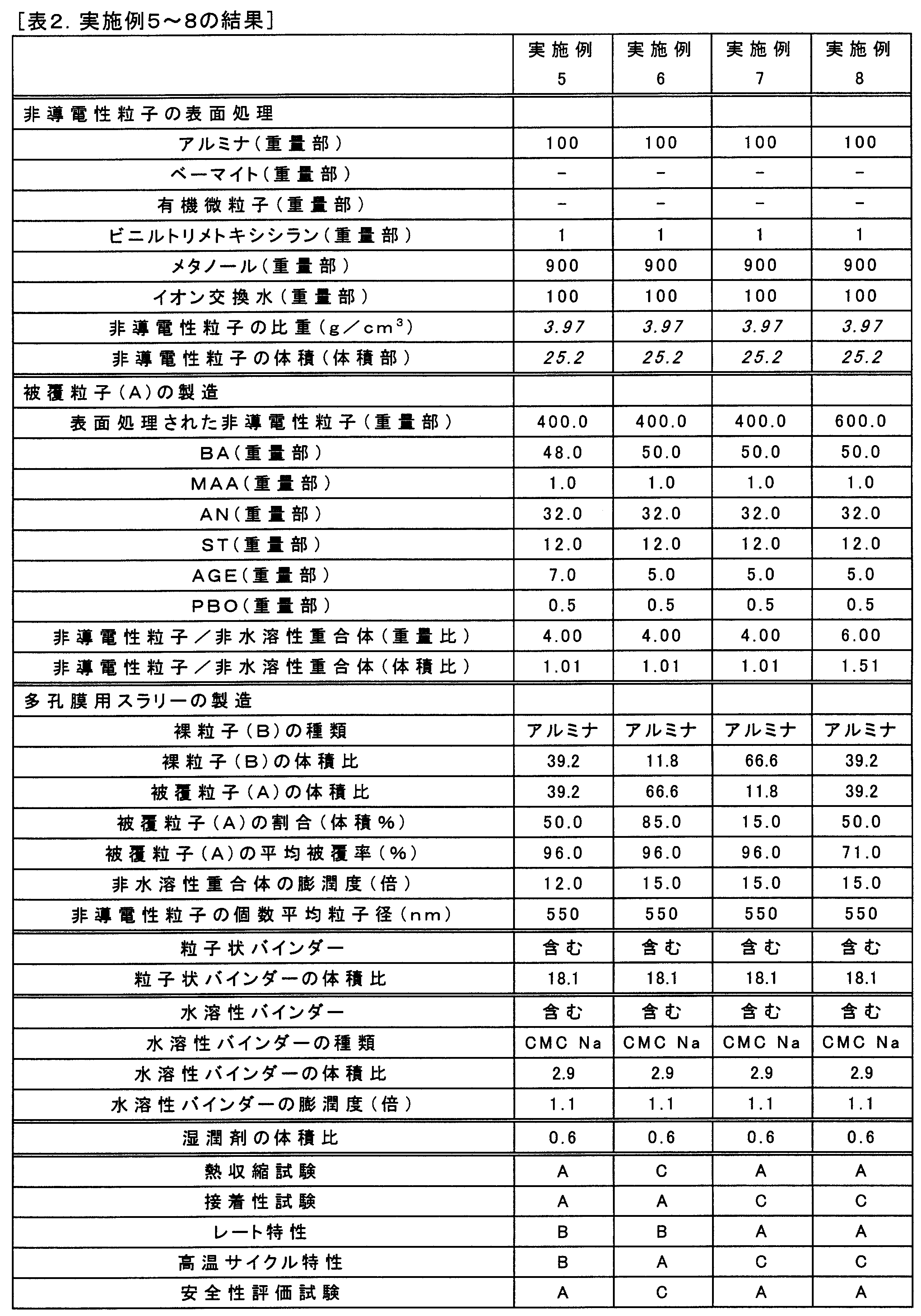


[検討]
前記の実施例及び比較例から分かるように、本発明の多孔膜を備えたセパレーターを用いることにより、安全性、高温サイクル特性及びレート特性のいずれにも優れる二次電池を実現することができる。
前記の実施例及び比較例から分かるように、本発明の多孔膜を備えたセパレーターを用いることにより、安全性、高温サイクル特性及びレート特性のいずれにも優れる二次電池を実現することができる。
10 被覆粒子(A)
10S 被覆粒子(A)の表面
11 非導電性粒子
11S 非導電性粒子の表面
12 非水溶性重合体
20 裸粒子(B)
30 絶縁粒子
40 粒子状バインダー
50 水溶性バインダー
10S 被覆粒子(A)の表面
11 非導電性粒子
11S 非導電性粒子の表面
12 非水溶性重合体
20 裸粒子(B)
30 絶縁粒子
40 粒子状バインダー
50 水溶性バインダー
Claims (8)
- 非導電性粒子を有する絶縁粒子、粒子状バインダー、水溶性バインダー及び媒体を含み、
前記絶縁粒子の15体積%~85体積%が、前記非導電性粒子の表面を覆い当該絶縁粒子の表面の70%以上を占める非水溶性重合体を有し、
50℃で10分間乾燥しさらに105℃で3時間乾燥させた前記非水溶性重合体の非水電解液に対する膨潤度が、10倍~50倍である、二次電池セパレーターの多孔膜用スラリー。 - 前記非導電性粒子の個数平均粒子径が、100nm~2000nmである、請求項1記載の多孔膜用スラリー。
- 50℃で10分間乾燥しさらに105℃で3時間乾燥させた前記水溶性バインダーの非水電解液に対する膨潤度が、1倍~5倍である、請求項1又は2記載の多孔膜用スラリー。
- 前記媒体が、水系媒体である、請求項1~3のいずれか一項に記載の多孔膜用スラリー。
- 非導電性粒子を有する絶縁粒子、粒子状バインダー及び水溶性バインダーを含む、二次電池セパレーター用多孔膜であって、
前記絶縁粒子の15体積%~85体積%が、前記非導電性粒子の表面を覆い当該絶縁粒子の表面の70%以上を占める非水溶性重合体を有し、
前記非水溶性重合体の非水電解液に対する膨潤度が、10倍~50倍である、二次電池セパレーター用多孔膜。 - 請求項5記載の二次電池セパレーター用多孔膜の製造方法であって、
請求項1~4のいずれか一項に記載の多孔膜用スラリーを基材上に塗布してスラリー層を得ること、及び、
前記スラリー層を乾燥すること、を含む、二次電池セパレーター用多孔膜の製造方法。 - 有機セパレーター層、及び、
前記有機セパレーター層上に形成された、請求項5記載の二次電池セパレーター用多孔膜を備える、二次電池用セパレーター。 - 正極、負極、請求項7記載の二次電池用セパレーター及び非水電解液を備える、二次電池。
Priority Applications (1)
| Application Number | Priority Date | Filing Date | Title |
|---|---|---|---|
| JP2015504343A JP6233404B2 (ja) | 2013-03-07 | 2014-03-04 | 二次電池セパレーターの多孔膜用スラリー、二次電池セパレーター用多孔膜及びその製造方法、二次電池用セパレーター並びに二次電池 |
Applications Claiming Priority (2)
| Application Number | Priority Date | Filing Date | Title |
|---|---|---|---|
| JP2013-045962 | 2013-03-07 | ||
| JP2013045962 | 2013-03-07 |
Publications (1)
| Publication Number | Publication Date |
|---|---|
| WO2014136799A1 true WO2014136799A1 (ja) | 2014-09-12 |
Family
ID=51491314
Family Applications (1)
| Application Number | Title | Priority Date | Filing Date |
|---|---|---|---|
| PCT/JP2014/055516 WO2014136799A1 (ja) | 2013-03-07 | 2014-03-04 | 二次電池セパレーターの多孔膜用スラリー、二次電池セパレーター用多孔膜及びその製造方法、二次電池用セパレーター並びに二次電池 |
Country Status (2)
| Country | Link |
|---|---|
| JP (1) | JP6233404B2 (ja) |
| WO (1) | WO2014136799A1 (ja) |
Cited By (6)
| Publication number | Priority date | Publication date | Assignee | Title |
|---|---|---|---|---|
| JP2016122611A (ja) * | 2014-12-25 | 2016-07-07 | 日本ゼオン株式会社 | 非水系二次電池機能層用組成物、非水系二次電池用機能層および非水系二次電池 |
| WO2017122540A1 (ja) * | 2016-01-13 | 2017-07-20 | 昭和電工株式会社 | 二次電池電極用水系バインダー組成物、二次電池電極用スラリー、バインダー、二次電池電極、および二次電池 |
| JP2017538248A (ja) * | 2014-10-24 | 2017-12-21 | エルジー・ケム・リミテッド | 有機無機複合多孔層を含む二次電池用セパレータ及びこの製造方法 |
| CN113261152A (zh) * | 2019-01-16 | 2021-08-13 | 三星Sdi株式会社 | 用于锂二次电池的隔板和包括其的锂二次电池 |
| WO2022114033A1 (ja) * | 2020-11-30 | 2022-06-02 | 日本ゼオン株式会社 | 二次電池機能層用バインダー、二次電池機能層用スラリー組成物、二次電池用機能層、および二次電池 |
| US12136743B2 (en) | 2018-12-26 | 2024-11-05 | Samsung Sdi Co., Ltd. | Separator for lithium secondary battery, and lithium secondary battery comprising same |
Families Citing this family (1)
| Publication number | Priority date | Publication date | Assignee | Title |
|---|---|---|---|---|
| CN111712944B (zh) * | 2018-11-14 | 2022-11-25 | 株式会社Lg新能源 | 用于锂二次电池的隔板及制造该隔板的方法 |
Citations (7)
| Publication number | Priority date | Publication date | Assignee | Title |
|---|---|---|---|---|
| JP2007280911A (ja) * | 2006-03-17 | 2007-10-25 | Sanyo Electric Co Ltd | 非水電解質電池及びその製造方法 |
| JP2007294437A (ja) * | 2006-03-29 | 2007-11-08 | Hitachi Maxell Ltd | 電池用セパレータおよびリチウム二次電池 |
| JP2008177595A (ja) * | 2005-12-08 | 2008-07-31 | Hitachi Maxell Ltd | 電気化学素子用セパレータおよび電気化学素子 |
| WO2009096528A1 (ja) * | 2008-01-30 | 2009-08-06 | Zeon Corporation | 多孔膜および二次電池電極 |
| WO2009123168A1 (ja) * | 2008-03-31 | 2009-10-08 | 日本ゼオン株式会社 | 多孔膜および二次電池電極 |
| WO2012029805A1 (ja) * | 2010-08-31 | 2012-03-08 | 日本ゼオン株式会社 | 電池多孔膜用スラリー組成物、二次電池用多孔膜の製造方法、二次電池用多孔膜、二次電池用電極、二次電池用セパレーター及び二次電池 |
| WO2013125645A1 (ja) * | 2012-02-23 | 2013-08-29 | 日本ゼオン株式会社 | 二次電池用多孔膜、二次電池用電極、二次電池用セパレーター及び二次電池 |
Family Cites Families (1)
| Publication number | Priority date | Publication date | Assignee | Title |
|---|---|---|---|---|
| JP2008017595A (ja) * | 2006-07-05 | 2008-01-24 | Matsushita Electric Ind Co Ltd | 車両用インバータ装置 |
-
2014
- 2014-03-04 JP JP2015504343A patent/JP6233404B2/ja active Active
- 2014-03-04 WO PCT/JP2014/055516 patent/WO2014136799A1/ja active Application Filing
Patent Citations (7)
| Publication number | Priority date | Publication date | Assignee | Title |
|---|---|---|---|---|
| JP2008177595A (ja) * | 2005-12-08 | 2008-07-31 | Hitachi Maxell Ltd | 電気化学素子用セパレータおよび電気化学素子 |
| JP2007280911A (ja) * | 2006-03-17 | 2007-10-25 | Sanyo Electric Co Ltd | 非水電解質電池及びその製造方法 |
| JP2007294437A (ja) * | 2006-03-29 | 2007-11-08 | Hitachi Maxell Ltd | 電池用セパレータおよびリチウム二次電池 |
| WO2009096528A1 (ja) * | 2008-01-30 | 2009-08-06 | Zeon Corporation | 多孔膜および二次電池電極 |
| WO2009123168A1 (ja) * | 2008-03-31 | 2009-10-08 | 日本ゼオン株式会社 | 多孔膜および二次電池電極 |
| WO2012029805A1 (ja) * | 2010-08-31 | 2012-03-08 | 日本ゼオン株式会社 | 電池多孔膜用スラリー組成物、二次電池用多孔膜の製造方法、二次電池用多孔膜、二次電池用電極、二次電池用セパレーター及び二次電池 |
| WO2013125645A1 (ja) * | 2012-02-23 | 2013-08-29 | 日本ゼオン株式会社 | 二次電池用多孔膜、二次電池用電極、二次電池用セパレーター及び二次電池 |
Cited By (10)
| Publication number | Priority date | Publication date | Assignee | Title |
|---|---|---|---|---|
| JP2017538248A (ja) * | 2014-10-24 | 2017-12-21 | エルジー・ケム・リミテッド | 有機無機複合多孔層を含む二次電池用セパレータ及びこの製造方法 |
| US10541399B2 (en) | 2014-10-24 | 2020-01-21 | Lg Chem, Ltd. | Secondary battery separator comprising organic/inorganic composite porous layer, and manufacturing method therefor |
| JP2016122611A (ja) * | 2014-12-25 | 2016-07-07 | 日本ゼオン株式会社 | 非水系二次電池機能層用組成物、非水系二次電池用機能層および非水系二次電池 |
| WO2017122540A1 (ja) * | 2016-01-13 | 2017-07-20 | 昭和電工株式会社 | 二次電池電極用水系バインダー組成物、二次電池電極用スラリー、バインダー、二次電池電極、および二次電池 |
| JPWO2017122540A1 (ja) * | 2016-01-13 | 2018-11-01 | 昭和電工株式会社 | 二次電池電極用水系バインダー組成物、二次電池電極用スラリー、バインダー、二次電池電極、および二次電池 |
| US11063260B2 (en) | 2016-01-13 | 2021-07-13 | Showa Denko K.K. | Aqueous binder composition for secondary battery electrode, slurry for secondary battery electrode, binder, secondary battery electrode, and secondary battery |
| US12136743B2 (en) | 2018-12-26 | 2024-11-05 | Samsung Sdi Co., Ltd. | Separator for lithium secondary battery, and lithium secondary battery comprising same |
| CN113261152A (zh) * | 2019-01-16 | 2021-08-13 | 三星Sdi株式会社 | 用于锂二次电池的隔板和包括其的锂二次电池 |
| US20220052419A1 (en) * | 2019-01-16 | 2022-02-17 | Samsung Sdi Co., Ltd. | Separator for lithium secondary battery, and lithium secondary battery comprising same |
| WO2022114033A1 (ja) * | 2020-11-30 | 2022-06-02 | 日本ゼオン株式会社 | 二次電池機能層用バインダー、二次電池機能層用スラリー組成物、二次電池用機能層、および二次電池 |
Also Published As
| Publication number | Publication date |
|---|---|
| JP6233404B2 (ja) | 2017-11-22 |
| JPWO2014136799A1 (ja) | 2017-02-16 |
Similar Documents
| Publication | Publication Date | Title |
|---|---|---|
| JP6287862B2 (ja) | 二次電池セパレーターの多孔膜用スラリー、二次電池セパレーター用多孔膜及びその製造方法、二次電池用セパレーター並びに二次電池 | |
| JP6451732B2 (ja) | 二次電池多孔膜用バインダー組成物、二次電池多孔膜用スラリー、二次電池用多孔膜及び二次電池 | |
| KR101819067B1 (ko) | 이차 전지용 정극 및 그 제조 방법, 슬러리 조성물, 그리고 이차 전지 | |
| JP6601404B2 (ja) | リチウムイオン二次電池多孔膜用組成物、リチウムイオン二次電池用多孔膜およびリチウムイオン二次電池 | |
| KR101996361B1 (ko) | 2 차 전지용 다공막 및 그 제조 방법, 2 차 전지용 전극, 2 차 전지용 세퍼레이터 그리고 2 차 전지 | |
| JP6052290B2 (ja) | リチウムイオン二次電池電極用のスラリー組成物、リチウムイオン二次電池用電極及びリチウムイオン二次電池 | |
| JP6135258B2 (ja) | 二次電池多孔膜用スラリー、二次電池用多孔膜及びその製造方法、並びに用途 | |
| JP6273956B2 (ja) | 二次電池多孔膜用バインダー、二次電池多孔膜用スラリー組成物、二次電池用多孔膜及び二次電池 | |
| KR102569981B1 (ko) | 2차 전지 다공막용 조성물, 2차 전지용 다공막 및 2차 전지 | |
| JP6327251B2 (ja) | リチウムイオン二次電池用多孔膜スラリー組成物、リチウムイオン二次電池用セパレーター、リチウムイオン二次電池用電極及びリチウムイオン二次電池 | |
| JP6233404B2 (ja) | 二次電池セパレーターの多孔膜用スラリー、二次電池セパレーター用多孔膜及びその製造方法、二次電池用セパレーター並びに二次電池 | |
| KR102493659B1 (ko) | 비수계 2차 전지 기능층용 조성물, 비수계 2차 전지용 기능층 및 비수계 2차 전지 | |
| JP2014149936A (ja) | 二次電池用セパレータ、二次電池用セパレータの製造方法及び二次電池 | |
| KR20150016937A (ko) | 2 차 전지용 부극 및 그 제조 방법 | |
| JP2014149935A (ja) | 二次電池用セパレータ、二次電池用セパレータの製造方法及び二次電池 | |
| JP2011076981A (ja) | 二次電池用正極の製造方法、二次電池正極用スラリー及び二次電池 | |
| JP6485459B2 (ja) | リチウムイオン二次電池用多孔膜およびリチウムイオン二次電池 | |
| JP6236964B2 (ja) | リチウムイオン二次電池用多孔膜組成物、リチウムイオン二次電池用セパレーター、リチウムイオン二次電池用電極、及びリチウムイオン二次電池 | |
| KR20170132160A (ko) | 이차 전지 다공막용 조성물, 이차 전지용 다공막 및 이차 전지 | |
| JP6233131B2 (ja) | 二次電池多孔膜用組成物、二次電池用多孔膜及び二次電池 | |
| KR20200060391A (ko) | 비수계 이차 전지 기능층용 조성물, 비수계 이차 전지용 기능층 및 비수계 이차 전지 | |
| JP6304039B2 (ja) | 二次電池セパレーターの多孔膜用スラリー、二次電池セパレーター用多孔膜及びその製造方法、二次電池用セパレーター並びに二次電池 | |
| JP6340826B2 (ja) | 二次電池多孔膜用スラリー、製造方法、二次電池用多孔膜、及び二次電池 | |
| WO2018163761A1 (ja) | 非水系二次電池機能層用組成物、非水系二次電池用機能層および非水系二次電池 | |
| JP2014203805A (ja) | リチウムイオン二次電池負極用粒子状バインダー、リチウムイオン二次電池負極用スラリー組成物およびリチウムイオン二次電池 |
Legal Events
| Date | Code | Title | Description |
|---|---|---|---|
| 121 | Ep: the epo has been informed by wipo that ep was designated in this application |
Ref document number: 14760261 Country of ref document: EP Kind code of ref document: A1 |
|
| ENP | Entry into the national phase |
Ref document number: 2015504343 Country of ref document: JP Kind code of ref document: A |
|
| NENP | Non-entry into the national phase |
Ref country code: DE |
|
| 122 | Ep: pct application non-entry in european phase |
Ref document number: 14760261 Country of ref document: EP Kind code of ref document: A1 |