WO2014136159A1 - モジュールソケット、無線モジュールの検査装置、及び無線モジュールの検査方法 - Google Patents
モジュールソケット、無線モジュールの検査装置、及び無線モジュールの検査方法 Download PDFInfo
- Publication number
- WO2014136159A1 WO2014136159A1 PCT/JP2013/006821 JP2013006821W WO2014136159A1 WO 2014136159 A1 WO2014136159 A1 WO 2014136159A1 JP 2013006821 W JP2013006821 W JP 2013006821W WO 2014136159 A1 WO2014136159 A1 WO 2014136159A1
- Authority
- WO
- WIPO (PCT)
- Prior art keywords
- antenna
- module
- wireless module
- installation
- module socket
- Prior art date
- Legal status (The legal status is an assumption and is not a legal conclusion. Google has not performed a legal analysis and makes no representation as to the accuracy of the status listed.)
- Ceased
Links
Images







Classifications
-
- G—PHYSICS
- G01—MEASURING; TESTING
- G01R—MEASURING ELECTRIC VARIABLES; MEASURING MAGNETIC VARIABLES
- G01R29/00—Arrangements for measuring or indicating electric quantities not covered by groups G01R19/00 - G01R27/00
- G01R29/08—Measuring electromagnetic field characteristics
- G01R29/10—Radiation diagrams of antennas
- G01R29/105—Radiation diagrams of antennas using anechoic chambers; Chambers or open field sites used therefor
-
- G—PHYSICS
- G01—MEASURING; TESTING
- G01R—MEASURING ELECTRIC VARIABLES; MEASURING MAGNETIC VARIABLES
- G01R1/00—Details of instruments or arrangements of the types included in groups G01R5/00 - G01R13/00 and G01R31/00
- G01R1/02—General constructional details
- G01R1/04—Housings; Supporting members; Arrangements of terminals
- G01R1/0408—Test fixtures or contact fields; Connectors or connecting adaptors; Test clips; Test sockets
- G01R1/0433—Sockets for IC's or transistors
- G01R1/0441—Details
- G01R1/045—Sockets or component fixtures for RF or HF testing
-
- G—PHYSICS
- G01—MEASURING; TESTING
- G01R—MEASURING ELECTRIC VARIABLES; MEASURING MAGNETIC VARIABLES
- G01R31/00—Arrangements for testing electric properties; Arrangements for locating electric faults; Arrangements for electrical testing characterised by what is being tested not provided for elsewhere
- G01R31/28—Testing of electronic circuits, e.g. by signal tracer
- G01R31/282—Testing of electronic circuits specially adapted for particular applications not provided for elsewhere
- G01R31/2822—Testing of electronic circuits specially adapted for particular applications not provided for elsewhere of microwave or radiofrequency circuits
Definitions
- the present disclosure relates to a module socket, a wireless module inspection device, and a wireless module inspection method.
- module performance is inspected before product shipment, for example.
- a module to be inspected is installed on an installation table for inspecting a module that is a part of the inspection apparatus.
- various characteristics for example, circuit characteristics
- An electronic device antenna and a measurement antenna are housed inside a test box having a radio wave absorber, and the radio waves radiated from the electronic device antenna are received by the measurement antenna.
- An apparatus for testing performance is known (see, for example, Patent Document 1).
- the present disclosure has been made in view of the above circumstances, and provides a module socket, a wireless module inspection apparatus, and a wireless module inspection method that can improve the reliability of module characteristics in the inspection of a wireless module.
- the module socket according to the present disclosure includes a base member having an installation surface in contact with a mounting surface on which the antenna is mounted in a wireless module including an antenna, and a radio wave from the antenna in a state where the wireless module is installed on the installation surface. And a gap formed within a predetermined distance in the radial direction.
- the reliability of the module characteristics in the inspection of the wireless module can be improved.
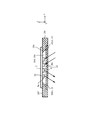
- Sectional drawing which shows the example of whole structure of the test
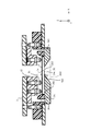
- Sectional drawing which shows an example of the shape of the installation stand in which the wireless module in 1st Embodiment was installed
- Sectional drawing which shows the 1st modification of the shape of the installation stand in which the wireless module in 1st Embodiment was installed
- A) Sectional drawing which shows the 2nd modification of the shape of the installation base in which the wireless module in 1st Embodiment was installed
- a conventional module inspection apparatus when inspecting the module characteristics of a wireless module having an antenna, the inspection apparatus is provided with an antenna that receives radio waves radiated from a wireless module to be inspected.
- an installation base made of, for example, resin exists between the antenna of the wireless module and the antenna of the inspection apparatus.
- the installation base interferes with the radio wave radiated from the wireless module, and changes the radio wave radiation pattern. As a result, the reliability of the module characteristics as the inspection result of the wireless module is lowered.
- the installation base of the following embodiment is provided in a wireless module inspection device, and is applied to, for example, an installation base on which a wireless module that transmits or receives radio waves in a high band including a millimeter wave band is installed.
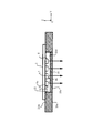
- FIG. 1 is a cross-sectional view showing an example of the overall configuration of an inspection apparatus 1 according to an embodiment.
- FIG. 2 is a partially enlarged cross-sectional view showing the vicinity of the installation table 20 of FIG.
- the inspection apparatus 1 measures a radiation pattern of radio waves radiated from the wireless module 5 that is an inspection target (DUT: Device Under Test).
- the inspection apparatus 1 includes an IC handler 3, a pusher 10, an installation table 20, and a dark box 40.
- the installation table 20 is an example of a module socket in which the wireless module 5 is installed.
- the IC handler 3 has a suction pad (not shown) for picking up the wireless module 5 and contact pins 12 that are pressed by the pusher 10 and come into contact with the wireless module 5.
- the contact pin 12 is an example of a contact.
- the IC handler 3 When installing the wireless module 5 on the installation table 20, the IC handler 3 sucks the surface of the wireless module 5 with the suction pad to pick up the wireless module 5, then moves to the upper part of the installation table 20, and moves to the installation table 20. Place.
- the pusher 10 is movable in the vertical direction (Z direction) and descends to press the contact pin 12 of the IC handler 3.
- a predetermined load is applied to the IC handler 3
- the contact pins 12 of the IC handler 3 come into contact with, for example, electrode terminals 5 b formed on the surface of the wireless module 5 installed on the installation table 20.
- the predetermined load is, for example, about 20 g per one electrode terminal 5b.
- a predetermined signal or power for inspection is supplied from the contact pin 12 of the IC handler 3 to the electrode terminal 5b formed in the wireless module 5.
- a radio wave for example, a radio wave in the millimeter wave band
- the antenna 8 receives radio waves radiated from the measurement antenna 43 provided in the inspection apparatus 1.
- the dark box 40 includes a radio wave absorber 47 that absorbs unnecessary radio waves from outside the dark box 40 on the inner wall surface of the dark box 40.
- the dark box 40 is an example of an antenna housing portion that houses the measurement antenna 43 of the inspection apparatus 1.
- the dark box 40 is surrounded by a radio wave absorber 47.
- the dark box 40 includes a measurement antenna 43 that receives radio waves radiated from the radio module 5 or radiates radio waves to the radio module 5.
- the measurement antenna 43 is an example of a second antenna. Further, as the measurement antenna 43, a transmission antenna and a reception antenna may be provided separately.
- the dark box 40 includes a module characteristic measurement unit that measures the intensity of the radio wave received or transmitted by the measurement antenna 43, for example.
- the measurement antenna 43 is installed on a mount 43b supported by four legs 43a, for example, with the center position of the measurement antenna 43 fixed. Further, the measurement antenna 43 can receive radio waves in a directivity direction other than the vertical direction (Z-axis direction) by tilting the four legs 43a. By adjusting the inclination of the four legs 43a to change the reception direction of the radio wave, the module characteristic measurement measures the intensity of the radio wave received by the measurement antenna 43, so that the radiation pattern of the radio wave radiated from the antenna 8 is changed. You can get it.
- the number of legs that support the gantry 43b may be other than four.
- FIG. 12A is a schematic perspective view of the installation base auxiliary member 35 installed in the dark box 40 as viewed from above.
- FIG. 12B is a schematic perspective view of the dark box 40 as viewed from above. In FIG. 12A, the vicinity of the installation base auxiliary member 35 in the entire dark box 40 is partially enlarged, and in FIG. 12B, the vicinity of the opening 40A in the entire dark box 40 is partially shown. It expands and shows.
- the coupling member 34 and the installation base auxiliary member 35 are installed on the ceiling surface 40B of the dark box 40.
- the coupling member 34 is a member for coupling the dark box 40 and the installation base auxiliary member 35 by, for example, screwing.
- the installation table auxiliary member 35 assists the installation of the installation table 20 in the dark box 40.
- the installation base auxiliary member 35 is provided with a buffer material 46, and the installation table 20 is installed via the buffer material 46.
- the coupling member 34 and the installation base auxiliary member 35 include openings 34a and 35a, respectively.
- the size of the opening 34a is, for example, substantially the same size as the opening 40A of the dark box 40. Further, the opening 40A of the dark box 40, the opening 34a of the coupling member 34, and the opening 35a of the installation base auxiliary member 35 are formed at substantially the same position in the XY plane and penetrate in the Z-axis direction.
- the opening 40A has a larger cross-sectional area on the XY plane on the inner wall surface side than on the outer wall surface side of the dark box 40, for example.
- size of the said cross-sectional area inside and outside the dark box 40 may be comparable.
- the opening 40A is formed, for example, in a columnar shape on the ceiling surface 40B of the dark box 40.
- the size of the opening 40A is determined based on, for example, the directivity direction of the antenna 8 and the restrictions for installing the buffer material 46 and the installation table 20 on the ceiling surface 40B of the dark box 40.
- the gasket 32 shown in FIG. 1A is a kind of cushioning material disposed between the dark box 40 and the inspection board 33. Since various components are mounted on the opposite surface of the inspection board 33 that faces the dark box 40, the inspection board 33 is not usually placed directly on the dark box 40. The gasket 32 creates a space between the dark box 40 and the inspection board 33.
- the size of the opening 40A is restricted by the arrangement of the gasket 32, for example.
- a reception antenna is mainly shown as the measurement antenna 43, when a transmission antenna is separately provided in the dark box 40, radio waves can be transmitted from a direction different from reception.
- the radio wave radiated from the measurement antenna 43 is received by the antenna 8 of the wireless module 5.
- the installation base 20 is formed into a socket type by using, for example, a dielectric material (for example, resin), and a guide member 20 b that guides the installed wireless module 5 to the inside of the installation base 20, and a wireless module 5 has a pedestal member 20a installed in contact with the installation surface 20p.
- the pedestal member 20a has an opening 20e.
- the opening 20e is an example of a gap formed within a predetermined distance from the antenna 8 in the radio wave radiation direction in a state where the wireless module 5 is installed on the installation surface 20p.
- the opening 20e formed in, for example, substantially the center of the installation surface 20p of the pedestal member 20a is formed in a recess 20d that becomes a recess, for example.
- a lid 20c is provided on the bottom surface 22 of the recess 20d.
- the opening 20e may be formed in the hole as will be described later.
- the recess 20d creates a gap within a predetermined distance from the antenna 8 mounted on the mounting surface 5a of the wireless module 5 in a state where the wireless module 5 is installed on the installation surface 20p of the base member 20a. Further, when the wireless module 5 is inspected, the contact pin 12 of the IC handler 3 comes into contact with the electrode terminal 5b of the wireless module 5 placed on the installation table 20.
- FIGS. 3A to 3D are plan views or cross-sectional views showing an example of the shape of the installation base 20 on which the wireless module 5 is installed.
- FIG. 3A is a plan view of the installation table 20 on which one wireless module 5 is installed as viewed from above (Z-axis positive direction).
- FIG. 3B is a schematic view of the A-A ′ cross section of the installation table 20 of FIG.
- FIG. 3C is a plan view of the installation table 20 on which a plurality of wireless modules 5 are installed as viewed from above (Z-axis positive direction).
- FIG. 3D is a schematic view of a cross section taken along the line B-B ′ of the installation table 20 of FIG. In FIGS. 3A to 3D, the guide member 20b is omitted.
- the plurality of wireless modules 5 are arranged in a lattice shape, for example, but may be arranged in other shapes.
- the installation base 20 on which one wireless module 5 is installed will be mainly described, but the same applies to the case of a large number.
- the opening 20e formed at the approximate center of the installation surface 20p of the pedestal member 20a includes a wall surface 21 (an example of a first surface) and a bottom surface 22 (second surface) of the pedestal member 20a. Is formed as a recess 20d having an example of the surface of The wall surface 21 is connected to the installation surface 20p.
- the bottom surface 22 is connected to the wall surface 21 and substantially faces the installation surface 20p.
- the bottom surface 22 of the recess 20d is formed by, for example, a lid 20c that is mounted on the opening 20e of the base member 20a so as to face the wireless module 5 to be inspected.
- the wall surface 21 of the recess 20d is connected to the installation surface 20p and the bottom surface 22, and is formed along the Z direction orthogonal to the bottom surface 22 (surface along the XY direction), for example.
- the length in the lateral direction (X-axis direction in FIGS. 3A to 3D) of the opening 20e formed in the base member 20a may be shorter or longer than the lateral length of the wireless module 5.
- the length of the opening 20e in the vertical direction (the Y-axis direction in FIGS. 3A to 3D) may be longer or shorter than the length of the wireless module 5 in the vertical direction.
- the opening 20e is an expression including the above-described recess 20d having the wall surface 21 and the bottom surface 22 and a hole 20f (see FIG. 6) penetrating a pedestal member 20a described later.
- the condition that the interference by the signal (reflected wave) reflected by the peripheral structure with respect to the signal (incident wave) radiated from the wireless module 5 is the smallest is that the phase difference of the reflected wave with respect to the incident wave is the wavelength ⁇ of the fundamental wave. For example, it is a case where it becomes approximately one quarter.
- the peripheral structure includes, for example, a wall surface 21 and a bottom surface 22 of the base member 20a.
- phase difference between the phase of the fundamental wave (Sin wave: sine wave) signal included in the radiated radio wave and the phase of the reflected wave signal is approximately 1 / 4 ⁇ , the combined wave of the incident wave and the reflected wave
- the peak value of the amplitude fluctuates while maintaining the shape of the Sin wave.
- the incident wave is a signal radiated from the antenna of the wireless module 5 and the reflected wave is a signal radiated from a structure around the antenna 8, for example, the amplitude of the synthesized wave varies. Therefore, the power peak value (the maximum amplitude value of the power waveform) varies depending on the presence or absence of the reflected wave. On the other hand, the shape (phase) of the combined wave of the incident wave and the reflected wave does not change. Therefore, the directivity can be measured stably without destroying the shape of the directivity of the antenna 8.
- the mounting surface 5a of the antenna 8 is perpendicular to the directivity direction (for example, the Z-axis direction) (for example, the X-axis direction and the Y-axis direction).
- the distance to the surface along the surface is set as follows, for example.
- the wavelength of the millimeter wave band is in the range of 1 mm to 10 mm. Therefore, the bottom surface 22 of the installation table 20 may be arranged at a position approximately a predetermined distance from the antenna 8 according to the wavelength ⁇ of the signal to be used (condition (1)). This predetermined distance is expressed by the following (formula 1). When the condition (1) is satisfied, the influence of the reflected wave reflected from the bottom surface 22 on the module characteristics including the antenna 8 can be suppressed to the minimum.
- the wall surface 21 of the installation base 20 may be disposed at a position of a predetermined distance or more from the antenna 8 according to the wavelength ⁇ of the signal to be used (condition (2)).
- This predetermined distance is the same as the distance represented by the above (Formula 1).
- FIG. 4 is a cross-sectional view showing an example of the shape of the installation base 20 on which the wireless module 5 is installed, and corresponds to FIG.
- the radio module 5 is installed on the installation surface 20 p with the mounting surface 5 a of the antenna 8 facing downward with respect to the base member 20 a of the installation table 20.
- the mounting surface 5a of the wireless module 5 is in contact with the installation surface 20p around the opening 20e.
- the opening 20e of the base member 20a has a wall surface 21 and a bottom surface 22 and is formed in a recess 20d in which the antenna 8 is accommodated.
- a lid portion 20c as a part for forming a recess 20d is provided below the pedestal member 20a.
- the thickness (length in the Z-axis direction) of the lid portion 20c is, for example, 2 mm.
- the directivity direction of the antenna 8 is downward (the direction of the Z-axis negative direction, the direction of the arrow in FIG. 4).
- the pusher 10 descends to press the contact pin 12 of the IC handler 3 and when a predetermined load is applied to the wireless module 5, the mounting surface 5a of the wireless module 5 is opened to the opening of the base member 20a.
- the periphery of the portion 20e is supported.
- the periphery of the opening 20e has rigidity with respect to a predetermined load, and for example, a deformation in which a substantially central portion of the wireless module 5 is bent downward is difficult to occur.
- the antenna 8 is opposed to and close to the surface of the lid 20c, that is, the bottom surface 22. Even in this case, when the above condition (1) is satisfied, the influence of the reflected wave on the signal in the directivity direction radiated from the antenna 8 can be suppressed.
- FIG. 5 is a sectional view showing a first modified example (installation table 20A) of the shape of the installation table 20 on which the wireless module 5 is installed.
- the recess 20d is formed such that the distance from the lower surface (front surface) 8b of the antenna 8 to the upper surface (bottom surface 22) of the lid portion 20c is 2 mm, for example. That is, in the installation table 20A, the pedestal member 20a is thicker than the installation table 20, and the depth of the recess 20d in which the antenna 8 is accommodated at the time of inspection is deep, and is within a predetermined range from the antenna 8 in the Z-axis direction. Has voids.
- the recess 20d is formed so that a distance ⁇ 1 from the end 8a in the horizontal direction (X-axis direction) of the antenna 8 to the wall surface 21 of the recess 20d is, for example, 2.4 mm or more.
- the thickness (length in the Z-axis direction) of the lid 20c is 2 mm, for example, and is the same as the installation table 20 of the second example. Further, the directivity direction of the antenna 8 is downward (Z-axis negative direction) in FIG.
- the distance ⁇ 2 (for example, 2 mm) from the lower surface 8b to the bottom surface 22 of the antenna 8 is, for example, a value close to about 1 ⁇ 4 of the wavelength ⁇ (for example, 8 mm) in the millimeter wave band. That is, in a state where the wireless module 5 is installed on the installation surface 20p of the pedestal member 20a, the distance from the antenna 8 to the bottom surface 22 is a predetermined distance represented by approximately (Expression 1). Thereby, the influence by the reflected wave with respect to the signal of the directivity direction radiated
- the distance ⁇ 1 (for example, 2.4 mm or more) from the wall surface 21 of the recess 20d to the end 8a of the antenna 8 is, for example, a value that is approximately 1 ⁇ 4 or more of the wavelength of the millimeter wave band (for example, 8 mm). That is, in a state where the wireless module 5 is installed on the installation surface 20p of the base member 20a, the distance from the antenna 8 to the wall surface 21 is approximately equal to or greater than the predetermined distance represented by (Equation 1). Thereby, the influence by the reflected wave with respect to signals other than a directivity direction can be suppressed.
- the recess 20d creates a gap in a predetermined range around the antenna 8, for example, it is possible to suppress the generation of reflected waves due to a resin material, and it is possible to suppress a decrease in module characteristics by suppressing changes in antenna characteristics.
- FIG. 6A is a cross-sectional view showing a second modification (installation table 20B) of the shape of the installation table 20 on which the wireless module 5 is installed.
- FIG. 6A shows a case where the installation base 20B is formed of a flexible member (for example, a rubber material or a sponge material). Further, a hole 20f that penetrates the pedestal member 20a in the direction (Z-axis direction) orthogonal to the installation surface 20p is formed as an opening 20e at, for example, the approximate center of the pedestal member 20a of the installation pedestal 20B. By forming the hole 20f, the base member 20a does not exist in the directivity direction of the antenna 8, and the influence of the reflected wave on the signal radiated from the antenna 8 can be suppressed.
- a hole 20f that penetrates the pedestal member 20a in the direction (Z-axis direction) orthogonal to the installation surface 20p is formed as an opening 20e at, for example, the approximate center of the pedestal member 20a of the installation pedestal 20B.
- the wireless module 5 When the wireless module 5 is inspected, when the pusher 10 descends and presses the contact pin 12 of the IC handler 3, the base member 20a of the installation base 20B that is pressed via the wireless module 5 is as indicated by an arrow a in the figure. Then, it bends so as to sink evenly downward (Z-axis negative direction). Thereby, the wireless module 5 does not bend downward, and the wireless module 5 can be maintained in a horizontal state. Therefore, the module characteristics of the wireless module 5 can be satisfactorily inspected while suppressing changes in the directivity direction.
- FIG. 6B is a cross-sectional view showing a third modification (installation table 20C) of the shape of the installation table 20 on which the wireless module 5 is installed.
- the spring member 31 is provided on the side opposite to the installation surface 20p of the base member 20a.
- the spring member 31 has a function as a damper that buffers a load applied to the installation table 20C.
- the spring member 31 has elasticity in the direction in which the installation surface 20p is pressed. Even when the pusher 10 is lowered, since the dark box 40 exists in the downward direction (pressing direction) of the installation table 20C, the base member 20a of the installation table 20C receives the elastic force of the spring member 31 and sinks downward. To avoid.
- the wireless module 5 does not bend downward and the wireless module 5 can be maintained in a horizontal state. Therefore, the module characteristics of the wireless module 5 can be satisfactorily inspected while suppressing changes in the directivity direction.
- Millimeter waves are electromagnetic waves (radio waves) having a wavelength of 1 mm to 10 mm and a frequency of 30 to 300 GHz.
- the transmission / reception characteristics of a signal radiated from the antenna 8 of the wireless module 5 using a millimeter-wave band signal are inspected, since the wavelength ⁇ becomes very short, the phase difference of the signal in the time difference between the incident wave and the reflected wave is reduced. Fluctuation is large. Accordingly, when the shape of the installation table 20 is not devised, for example, the influence on the quality of the signal of the millimeter wave band radiated from the antenna 8 by the signal reflected by the peripheral structure is the signal of the low frequency band. Appears more prominently.
- the installation table 20 there is a member made of, for example, a dielectric material around the antenna 8, and deterioration of directivity of the antenna 8 can be suppressed even when the wireless module 5 using a high band (for example, a millimeter wave band) is inspected.
- the radiation characteristics of the antenna 8 can be improved by forming the recess 20 d or the hole 20 f in the base member 20 a of the installation base 20.
- the wireless module 5 is installed on the base member 20a and a gap is generated within a predetermined distance from the antenna 8, it is less affected by reflected waves, and the reliability of module characteristics in the inspection of the wireless module 5 is improved. it can.
- the reliability of the module characteristics in the inspection of the wireless module 5 can be improved, and the module characteristics can be measured with high accuracy.
- the inspection device 1 of the second embodiment has the same configuration as the inspection device 1 of the first embodiment.
- description is abbreviate
- FIGS. 7A to 7D are plan views or cross-sectional views showing an example of the shape of the installation table 20D on which the wireless module 5 is installed.
- FIG. 7A is a plan view of an installation table 20D on which one wireless module 5 is installed as viewed from above (Z-axis positive direction).
- FIG. 7B is a schematic diagram of a C-C ′ cross section of the installation table 20 ⁇ / b> D of FIG.
- FIG. 7C is a plan view of the installation table 20D on which a plurality of wireless modules 5 are installed as viewed from above (Z-axis positive direction).
- FIG. 7D is a schematic diagram of a D-D ′ cross section of the installation table 20 ⁇ / b> D of FIG. 8C.
- the guide member 20b is omitted.
- the plurality of wireless modules 5 are arranged in a lattice shape, for example, but may be arranged in other shapes.
- the installation base 20D on which one wireless module 5 is installed will be mainly described, but the same applies to the case of a large number.
- the installation table 20D is formed into a socket type made of a resin material, for example, and has a base member 20a on which the wireless module 5 is installed.
- the pedestal member 20a has an opening 20e.
- a hole 20g that obliquely penetrates the pedestal member 20a is formed as an example of the opening 20e. That is, the hole 20g is inclined at a predetermined angle from the Z-axis direction.
- the wall surface 21 (inner wall surface) of the hole 20g has a tapered surface 20h along the directivity direction of the antenna 8.
- the opening 20e may be a recess 20d having a lid 20c instead of the hole 20g.
- the length of the hole 20g of the base member 20a in the horizontal direction is shorter than the length of the radio module 5 in the horizontal direction.
- the length of the hole 20g in the vertical direction (the Y direction in FIGS. 7A and 7B) is longer than the length of the wireless module 5 in the vertical direction.
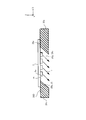
- FIG. 8 is a cross-sectional view showing an example of the shape of the installation table 20D on which the wireless module 5 is installed, and corresponds to FIG. 7B. Similar to the first embodiment, the installation base 20D includes a base member 20a on which the wireless module 5 is installed with the mounting surface 5a on which the antenna 8 is mounted facing downward.
- a hole 20g is formed as an opening 20e in the approximate center of the base member 20a.
- the wall surface 21 of the hole 20 g has a tapered surface 20 h along the directionality direction of the signal radiated from the antenna 8.
- the directivity direction of the antenna 8 is an obliquely downward direction from the antenna 8 as shown by an arrow b in FIG.
- the left and right wall surfaces 21 in FIG. 8 have a tapered surface 20h along the directivity direction during transmission and reception.
- the pusher 10 descends and presses the contact pin 12 of the IC handler 3.
- the periphery of the opening 20e of the base member 20a supports the mounting surface 5a of the wireless module 5.
- the periphery of the opening 20e has rigidity with respect to a predetermined load, and for example, a deformation in which a substantially central portion of the wireless module 5 is bent downward is difficult to occur.
- the wall surface 21 of the hole 20g is tapered along the directivity direction of the antenna 8 and the bottom surface of the installation base 20D does not exist, the influence of the reflected wave of the signal in the directivity direction is eliminated. Further, when the wireless module 5 is installed on the installation table 20D, since there is a gap from the wall surface 21 of the hole 20g to the end 8a of the antenna 8, the influence of reflected waves on signals other than the directivity direction can be suppressed. In addition, deterioration of directivity of the antenna 8 due to the presence of a member made of a dielectric material, for example, around the antenna 8 can be suppressed.
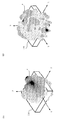
- FIGS. 9A and 9B are schematic diagrams illustrating an example of a radiation pattern p of a signal radiated from the antenna 8.
- the X-axis direction represents the horizontal direction of the installation table 20D
- the Y-axis direction represents the vertical direction of the installation table 20D
- the Z-axis direction represents the vertical direction of the installation table 20D.
- the mounting surface 5a of the antenna 8 of the wireless module 5 is arranged upward (Z-axis positive direction).
- the radio wave intensity is indicated by shading, and the radio wave intensity is higher as it is darker.
- antennas having the same directivity are used.
- FIG. 9A shows the simulation result of the radiation pattern p of the signal radiated from the wireless module 5 installed on the installation table 20D.
- FIG. 9B shows the simulation result of the radiation pattern p of the signal radiated from the wireless module installed on the conventional installation table 120.
- the installation surface in contact with the antenna mounting surface of the wireless module in the installation table 120 is flat with no recesses. That is, the installation table 120 has a uniform thickness (length in the Z-axis direction).
- the signal radiated from the antenna 8 has a radiation pattern p having a higher radio wave intensity in the directional direction of the antenna 8 than in the directional direction.
- a direction inclined by a predetermined angle from the positive Z-axis direction to the X-axis direction is the direction in which the radiated radio wave intensity is the highest, and the directivity direction It is.
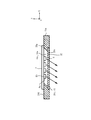
- FIG. 10 is a cross-sectional view showing a first modification (installation table 20E) of the shape of the installation table 20D on which the wireless module 5 is installed.
- the wall surface 21 of the recess 20d that is the opening 20e has a tapered surface 20h along the directivity direction.
- a lid 20c that forms the bottom surface 22 of the recess 20d is provided on the lower side of the installation table 20D in FIG.
- the thickness (length in the Z direction) of the lid 20c is, for example, 2 mm.
- the recess 20d is formed such that the distance from the lower surface 8b of the antenna 8 to the upper surface (bottom surface 22) of the lid portion 20c is 2 mm, for example.
- the recess 20d is formed such that the distance from the end 8a in the horizontal direction (X direction) of the antenna 8 to the tapered surface 20h is, for example, 2.4 mm or more.
- the distance (for example, 2 mm) from the bottom surface 8 b to the bottom surface 22 of the antenna 8 is approximately 1 ⁇ 4 of the wavelength in the millimeter wave band (for example, 8 mm), the distance from the signal in the directivity direction radiated from the antenna 8 The influence can be suppressed.
- the distance (for example, 2.4 mm or more) from the wall surface 21 of the recess 20d formed in the tapered surface 20h to the end 8a of the antenna 8 is approximately 1/4 or more of the wavelength of the millimeter wave band (for example, 8 mm). Therefore, it is possible to suppress the influence of the reflected wave on the signal other than the directivity direction.
- the installation base 20E has the lid portion 20c, the base member 20a that supports the mounting surface 5a of the wireless module 5 can be made strong against the load.
- FIG. 11 is a cross-sectional view showing a second modification (installation table 20F) of the shape of the installation table 20D on which the wireless module 5 is installed.
- installation table 20F a second modification of the shape of the installation table 20D on which the wireless module 5 is installed.
- FIG. 11 it is assumed that the antenna 8 has different directivity directions in transmission and reception.
- the installation base 20F has a tapered surface 20h1 along the directivity direction of the signal transmitted by the antenna 8 among the wall surfaces 21 on both sides of the recess 20d, and the other surface is received by the antenna 8.
- the tapered surface 20h1 may be along the directivity of the reception signal, and the tapered surface 20h2 may be along the directivity of the transmission signal.
- the installation table 20F is the same as the installation table 20E except that the installation table 20F has a divergent taper surface 20h.
- the distance between each position and the thickness (for example, 2 mm, 2.4 mm) are the same as those of the installation table 20E, and thus the description thereof is omitted.
- radio waves can be transmitted or received from different directions by using a reception antenna and a transmission antenna in the dark box 40 as the measurement antenna 43.
- the influence of the reflected wave from the wall surface 21 of the opening 20e on the signal in the directivity direction radiated from the antenna 8 can be suppressed.
- the influence by the reflected wave from the wall surface 21 of the opening part 20e with respect to the signal of the directivity direction received by the antenna 8 can be suppressed.
- the installation base has a hole as an opening.
- the inspection device 1 of the third embodiment has the same configuration as the inspection device 1 of the first embodiment.
- description is abbreviate
- FIG. 13 is a partially enlarged cross-sectional view showing an example of the vicinity of the installation table 20G in the third embodiment.
- the installation table 20G has a hole 20i as the opening 20e.
- the area of the opening end face (xy plane) 20i1 on the wireless module 5 side (Z-axis positive side) is smaller than the area of the opening end face 20i2 on the dark box 40 side (Z-axis negative side). That is, the installation table 20G is formed so that the installation table 20G does not interfere with radio waves radiated from the antenna 8 and spreading in the space.
- a tapered surface 20i3 is formed as a wall surface of the hole 20i from the opening end surface 20i1 toward the opening end surface 20i2.
- the angle ⁇ formed by the tapered surface 20 i 3 in the hole 20 i and the opening end surface 20 i 1 or the opening end surface 20 i 2 is determined according to the radiation pattern of the antenna 8, for example.
- the angle ⁇ is shown as an angle formed between the direction along the Z axis and the tapered surface 20 i 3.
- ⁇ 15 degrees may be added to the ⁇ 30 degrees so that the angle ⁇ is 45 degrees or more.
- the difference between the area of the opening end face 20i1 and the area of the opening end face 20i2 may be made as large as possible. In this case, the strength of the installation table 20 can be increased.
- FIG. 14 is a plan view of the installation table 20G as viewed from below (Z-axis negative direction).
- the opening end surface 20i1 is an end surface on the positive side of the Z axis of the hole 20i.
- the opening end surface 20i2 is an end surface on the negative side of the Z axis of the hole 20i.
- the antenna 8 mounted on the wireless module 5 can be confirmed in the opening end face 20i1.
- the opening end surfaces 20i1 and 20i2 are formed in a substantially rectangular shape, but may be formed in other shapes (for example, a substantially circular shape).
- the antenna 8 includes, for example, eight antenna elements and two 2 ⁇ 2 patch antennas.
- the shape of the patch antenna may be other than 2 ⁇ 2, and the number of patch antennas may be other than two.
- the distance d1 between each antenna element and the opening end face 20i1 is set to ⁇ / 2 or more, for example, where the wavelength corresponding to the communication frequency used by the antenna 8 is the wavelength ⁇ .
- the portion subjected to the pressing by the contact pin 12 is relatively wide, the deterioration of the radiated radio wave is suppressed, and the strength of the installation table 20G against the pressing can be ensured.
- the dielectric material for example, resin material
- the dielectric material is not disposed on the radiation direction of the radio wave from the antenna 8, that is, on the negative side of the Z-axis from the antenna 8, the reduction of the radiated radio wave intensity and the radiation pattern Deformation can be suppressed.
- 15A to 15C are plan views showing modified examples of the configuration of the hole 20i.
- the center of the wireless module 5 in the xy plane and the centers of the opening end surfaces 20i1 and 20i2 in the XY plane are arranged so as to substantially coincide with each other.
- the antenna elements are arranged in two rows along the Y-axis, but the distance d2 between the antenna elements arranged in the X-axis positive side row and the opening end face 20i1 is approximately ⁇ / 2.
- the distance d2 between the antenna elements arranged in the X-axis negative side row and the opening end face 20i1 is approximately ⁇ / 2 or more.
- the center of the antenna 8 may be arranged so as to be shifted from the center of the opening end face 20i1. Even in this case, the contact pin 12 (see FIG. 13) presses the wireless module 5 over a wider range on the X-axis negative side than on the X-axis positive side. Therefore, the wireless module 5 can be pressed evenly against the installation table 20G.
- the center of the wireless module 5 in the XY plane and the centers of the opening end surfaces 20i1 and 20i2 in the XY plane are arranged so as to substantially coincide with each other.
- the distance between each antenna element included in the antenna 8 and the opening end face 20i1 is approximately ⁇ / 2 or more.
- the area of the opening end surface 20 i 1 is formed slightly smaller than the area of the mounting surface 5 a of the wireless module 5.
- the opening end surface 20i1 is included in the range corresponding to the mounting surface 5a. Therefore, the hole 20i is formed larger than the case of FIG.
- the measurement accuracy of the wireless module 5 can be improved by further reducing interference between the radio wave radiated from the antenna 8 and the dielectric member and suppressing the change in antenna characteristics.
- the lengths of two opposing sides (here, sides 201 and 202) on the opening end face 20i1 are two sides (here, sides) of the wireless module 5 parallel to these two sides. 203, 204).
- the wireless module 5 is pressed by the contact pin 12 in the vicinity of two opposing sides (here, sides 201 and 202) of the wireless module 5.
- the wireless module 5 is not pressed by the contact pins 12.
- the distance between each antenna element included in the antenna 8 and the opening end face 20i1 is approximately ⁇ / 2 or more.
- the radio module 5 can be pressed and fixed, and the radio module 5 module characteristics can be measured.
- the hole 20i is formed in consideration of the radio wave radiated from the antenna 8 and spreading in the space, it is possible to suppress the radiated radio wave from interfering with the dielectric portion of the installation base 20G. Therefore, the measurement accuracy and inspection accuracy of the wireless module 5 can be improved by suppressing changes in antenna characteristics.
- the installation base 20i of the present embodiment is formed in a shape that takes into account the measurement of the characteristics of the wireless module 5 on which the antenna 8 is mounted, thereby suppressing changes in the antenna characteristics. Degradation of the measurement accuracy and inspection accuracy of the wireless module 5 can be suppressed.
- the fourth embodiment is a modification of the third embodiment.
- the characteristics of the module on which the antenna is mounted are measured using a radio wave absorber separate from the dark box 40 without using the dark box 40.
- FIG. 16 is a cross-sectional view showing a partial configuration example of the inspection apparatus 1B including the installation table 20G in the fourth embodiment.
- the inspection apparatus 1B does not include the dark box 40 illustrated in FIG. 1 but includes a radio wave absorber 44, an acrylic plate 45, and a measuring device 48.
- the same components as those of the inspection apparatus 1 shown in FIG. 1 or the installation base 20G shown in FIG. 13 are denoted by the same reference numerals, and description thereof is omitted or simplified.
- the radio wave absorber 44 absorbs the radio wave reflected from the measuring device 48 and reduces the radio wave traveling from the measuring device 48 to the wireless module 5.
- the acrylic plate 45 supports the radio wave absorber 44 and fixes the position of the radio wave absorber 44.
- the measuring device 48 includes, for example, the above-described measurement antenna 43 and a module characteristic measurement unit that measures the intensity of the radio wave received or transmitted by the measurement antenna 43.
- the radio wave absorber 44, the acrylic plate 45, and the measuring device 48 are arranged on the lower side (Z-axis negative side) of the installation table 20 ⁇ / b> G.
- the end of the radio wave absorber 44 on the center portion side of the antenna 8 in the X direction is disposed, for example, at a position on a substantially extended line of the tapered surface 20i3 of the hole 20i. Thereby, it can suppress that the reflected radio wave radiated
- the distance between the inspection board 33 and the acrylic plate 45 may be close as long as it does not interfere with the installation table 20G.
- the characteristics of the wireless module 5 on which the antenna 8 is mounted can be measured by downsizing the inspection apparatus 1B without using the dark box 40.
- the radio wave radiated from the wireless module 5 propagates while spreading in the space, but the reflected wave or radiated wave from the measuring device 48 is reduced by the radio wave absorber 44. Measurement accuracy can be improved.
- the wireless module is fixed to the installation base by pressing the wireless module with the contact pin, and the installation base is fixed to the inspection board 33.
- a module socket that fixes the wireless module 5 using a plurality of members using a hook will be described.
- a radio wave is radiated from the antenna 8 in the direction of the arrow a shown in FIG.
- the measuring device 48 shown in FIG. 16 or the device for measuring the module characteristics shown in FIG. 1 (for example, the measurement antenna 43 and the module characteristic measuring unit) is arranged.
- a dark box 40 is arranged.
- the module characteristic is measured by, for example, a method similar to the measurement method in the above-described embodiment.
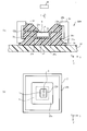
- FIG. 17A and 17B are a cross-sectional view and a plan view showing an example of the shape of the module socket 20H and members near the module socket 20H.
- FIG. 17A shows a cross section of the module socket 20H when viewed from the front (Y axis positive side).
- FIG. 17B shows the shape of the socket lid 23 when the module socket of FIG. 17A is viewed from above (Z-axis negative side).
- an antenna 8 that radiates radio waves is mounted in the Z axis direction, that is, in a direction substantially orthogonal to the mounting surface 5a.
- the module socket 20H includes a base portion 26, a socket lid 23, and a hook 25.
- the base unit 26 is mounted on an inspection board 33 that supplies power to the wireless module 5 and inputs and outputs signals.
- an inspection board 33 for example, a connector connected to the measuring instrument 48 or a power source (not shown), and an electronic component (for example, a capacitor, a power IC) as an external component of the wireless module 5 are mounted.
- the base portion 26 is formed with a recess 26a in which the wireless module 5 is accommodated.
- the wireless module 5 is installed on the installation surface 26e which is the bottom surface of the recess 26a.
- a plurality of conductive pins 27 that come into contact with each of the electrode terminals (balls) 5b of the wireless module 5 housed in the recess 26a are disposed.
- the conductive pin 27 protrudes from the installation surface 26e.
- the plurality of conductive pins 27 are connected to, for example, signal lines or power supply lines on the inspection board 33.
- the socket lid 23 is brought into contact with the mounting surface 5a of the wireless module 5 so as to press the wireless module 5 installed on the base portion 26.
- a projection (projection) 23e is formed at a substantially central portion of the socket lid 23, and a hole is formed as an opening 23a so as to penetrate the projection 23e in a direction along the Z axis.
- the shape of the cross section along the XY plane of the opening 23a may be a rectangular shape, a circular shape, or other shapes.
- the opening 23a has a small opening area on the lower side (Z-axis positive side) and a large opening area on the upper side (Z-axis positive side).
- the angle of the inner wall surface of the opening 23a is formed, for example, as a tapered slope inclined by 45 degrees with respect to the Z-axis direction.
- a distance d1 between the lower opening end 23d having the smallest opening area and the element of the antenna 8 is, for example, ⁇ / 2 or more.
- ⁇ is the wavelength of the radio wave radiated from the wireless module 5.
- the angle of the opening 23a varies depending on, for example, the radiation pattern of the radio wave from the antenna 8. For example, when the half-value angle of the antenna directivity is ⁇ 30 degrees, the angle of the opening 23a is ⁇ 45 degrees or more by adding ⁇ 15 degrees to the half-value angle. Thereby, both the ease of processing of the module socket 20H and the strength of the module socket 20H can be achieved.
- the socket lid 23 moves the wireless module 5 downward (Z-axis positive direction) by the convex portion 23e so that force is evenly applied to the vicinity of the four sides of the upper surface (Z-axis negative surface) of the wireless module 5. ).
- the antenna 8 is disposed at the substantially central portion of the wireless module 5, the peripheral portion of the wireless module 5 is pressed evenly.
- the antenna 8 is biased to one side of the wireless module 5, one end side in the X-axis direction and the other end in the X-axis direction are formed on the lower surface (surface on the Z-axis positive side) of the protrusion 23 e of the socket lid 23.
- the contact area with the wireless module 5 differs on the side. Even in this case, the wireless module 5 can be pressed evenly by the different surfaces of the wireless module 5.
- the hook 25 has a pair of locking pieces 25a and 25b that respectively engage with a hook portion 26c formed as a step portion on the base portion 26 and a hook portion 23b formed as a step portion on the socket lid 23.
- the hook 25 sandwiches and fixes the base portion 26 and the socket lid 23.
- the wireless module 5 is sandwiched between the base portion 26 and the socket lid 23.
- FIG. 17A it is exemplified that two hooks 25 are used, but three or more hooks 25 may be used.
- the wireless module 5 Before the start of the module characteristic inspection, the wireless module 5 is accommodated in the recess 26a of the base portion 26, and each of the plurality of electrode terminals 5b comes into contact with the plurality of conductive pins 27.
- the wireless module 5 is pressed by the convex portion 23 e of the socket lid 23, and the hook 25 sandwiches the socket lid 23 and the base portion 26. Thereby, the wireless module 5 is fixed in the module socket 20H.
- the influence of a member (for example, a resin member) of the module socket 20H can be suppressed.
- the measurement accuracy and inspection accuracy of the module characteristics of the wireless module 5 including the antenna 8 having directivity in a direction substantially orthogonal to the mounting surface 5a of the antenna 8 can be improved.
- a module characteristic measuring device for example, module characteristic measuring unit, measuring device 48
- the wireless module 5 is evenly pressed by the convex portion 23e of the socket lid 23, the electrode terminal 5b and the conductive pin 27 can be satisfactorily contacted. Therefore, for example, power supply to the wireless module 5 or signal input / output can be stably executed.
- the radio module 5 to be inspected can be easily replaced.
- the thickness of the module socket 20H can be reduced.
- the conductive pin 27 of the base portion 26 is connected to, for example, a signal line or a power supply line on the inspection board 33, signals necessary for the inspection of the wireless module 5 can be input / output.
- the opening 23a is formed in the socket lid 23
- a member formed of a dielectric for example, resin
- the influence on the module characteristics of the antenna 8 is suppressed. it can. Therefore, the measurement accuracy and inspection accuracy of the wireless module 5 can be improved by suppressing changes in antenna characteristics.
- the first module socket of the present disclosure includes: A pedestal member having an installation surface in contact with a mounting surface on which the antenna is mounted in a wireless module including the antenna; In a state where the wireless module is installed on the installation surface, a gap formed within a predetermined distance from the antenna toward the radio wave radiation direction, and Have
- the second module socket of the present disclosure is a first module socket,
- the pedestal member has a first surface connected to the installation surface,
- the gap has a hole that penetrates the base member.
- the third module socket of the present disclosure is a first module socket,
- the pedestal member includes a first surface connected to the installation surface; A second surface connected to the first surface and facing the installation surface, The gap has a recess formed by the first surface and the second surface.
- the fourth module socket of the present disclosure is a third module socket, In a state where the wireless module is installed on the installation surface, the distance from the antenna to the first surface is approximately when the wavelength of a radio wave transmitted or received by the antenna is ⁇ and the integer is n. It is not less than the distance represented by 1 ⁇ 4 ⁇ ⁇ ⁇ (4n + 1).
- the fifth module socket of the present disclosure is a third or fourth module socket, In a state where the wireless module is installed on the installation surface, the distance from the antenna to the second surface is approximately when the wavelength of a radio wave transmitted or received by the antenna is ⁇ and the integer is n. A distance represented by 1/4 ⁇ ⁇ ⁇ (4n + 1).
- the sixth module socket of the present disclosure is a third or fourth module socket,
- the first surface includes a tapered surface formed along the directivity direction of the antenna.
- the seventh module socket of the present disclosure is a sixth module socket,
- the first surface includes a tapered surface formed along substantially the same direction when the directivity direction of the antenna is substantially the same in transmission and reception of radio waves.
- the eighth module socket of the present disclosure is a sixth module socket, In the first surface, when the directivity direction of the antenna is different in transmission and reception of radio waves, A tapered surface formed along a first directivity direction in the transmission; A tapered surface formed along a second directivity direction in the reception; including.
- the ninth module socket of the present disclosure is any one of the first to eighth module sockets,
- the pedestal member has elasticity in a direction in which the installation surface is pressed.
- a tenth module socket of the present disclosure is a second module socket,
- the first surface includes a tapered surface formed along the directivity direction of the antenna;
- the hole includes a first opening end surface located on the installation surface side;
- a second opening end surface located on the opposite side of the installation surface and having a larger area than the area of the first opening end surface; including.
- the eleventh module socket of the present disclosure is a tenth module socket,
- the tapered surface has an inclination based on a half-value angle of the antenna with respect to an axis orthogonal to the installation surface.
- the twelfth module socket of the present disclosure is a tenth or eleventh module socket, In a state where the wireless module is installed on the installation surface, the distance from the antenna to the first surface is 1 ⁇ 2 ⁇ ⁇ when the wavelength of the radio wave transmitted or received by the antenna is ⁇ . Greater than or equal to the distance represented.
- a thirteenth module socket of the present disclosure is a twelfth module socket, The first opening end surface is located within a range facing the wireless module in a state where the wireless module is installed on the installation surface.
- a fourteenth module socket of the present disclosure is a twelfth module socket,
- the first opening end surface has a second direction in which both end portions in the first direction face the wireless module and are orthogonal to the first direction in a state where the wireless module is installed on the installation surface. Both ends of the do not face the wireless module.
- the wireless module inspection device of the present disclosure Any one of the first to fourteen module sockets; A contact that contacts the electrode terminal of the wireless module installed in the module socket and supplies a predetermined signal or power to the wireless module; A pusher that presses the contact toward the wireless module; A second antenna that receives radio waves radiated from a first antenna mounted on the wireless module, or radiates radio waves to the first antenna; An antenna housing portion surrounded by a radio wave absorber, facing the module socket, and housing the second antenna; Is provided.
- the wireless module inspection method of the present disclosure includes: Installing a wireless module in any one of the first to fourteenth module sockets; Abutting a contact for supplying a predetermined signal or power to the wireless module to an electrode terminal of the wireless module installed in the module socket; Pressing the contact toward the wireless module; A radio wave radiated from the first antenna mounted on the wireless module is received by the second antenna surrounded by the radio wave absorber and accommodated in the antenna accommodating portion facing the module socket, or the first antenna Radiating radio waves to the antenna; Have
- This disclosure is useful for a module socket, a wireless module inspection apparatus, and the like that can improve the reliability of module characteristics in the inspection of a wireless module.
Landscapes
- Physics & Mathematics (AREA)
- General Physics & Mathematics (AREA)
- Engineering & Computer Science (AREA)
- Electromagnetism (AREA)
- Computer Hardware Design (AREA)
- Microelectronics & Electronic Packaging (AREA)
- General Engineering & Computer Science (AREA)
- Variable-Direction Aerials And Aerial Arrays (AREA)
- Connecting Device With Holders (AREA)
- Manufacturing Of Electrical Connectors (AREA)
Abstract
Description
従来のモジュール検査装置では、アンテナを有する無線モジュールのモジュール特性を検査する場合、検査装置に、検査対象の無線モジュールから放射される電波を受信するアンテナが設けられる。設置台に無線モジュールが設置された状態において無線モジュールから電波を放射すると、無線モジュールのアンテナと検査装置のアンテナとの間に、例えば樹脂により形成された設置台が存在する。この場合、設置台が無線モジュールから放射された電波に干渉し、電波の放射パターンを変化させる。この結果、無線モジュールの検査結果としてのモジュール特性の信頼性が低下する。
例えば、ミリ波帯の波長は、1mm~10mmの範囲にある。従って、使用する信号の波長λに応じて、アンテナ8からおよそ所定距離の位置に、設置台20の底面22を配置してもよい(条件(1))。この所定距離は、以下の(式1)により表される。条件(1)を満たす場合、アンテナ8を加味したモジュール特性に対する、底面22により反射する反射波の影響を最小限に抑制できる。
第1の実施形態では、無線モジュール5のアンテナ8の指向性方向が、設置台20の設置面20pに直交する方向(Z軸方向)である場合を示した。第2の実施形態では、アンテナ8の指向性方向が、設置台20の設置面20pに直交する方向(Z軸方向)から所定角度ずれており、斜め方向である場合を示す。
第3の実施形態では、無線モジュール5のアンテナ8の指向性方向が、設置台の設置面に直交する方向(Z軸方向)又は直交する方向から所定角度傾斜した方向である場合について説明する。第3の実施形態では、設置台が開口部として孔部を有する。
図15(A)~(C)は、孔部20iの構成の変形例を示す平面図である。
(参考特許文献:日本国特開2009-245889号公報)
第4の実施形態は、第3の実施形態の変形例である。第4の実施形態では、暗箱40を用いず、暗箱40とは別体の電波吸収体を用いて、アンテナが実装されたモジュールの特性を計測する。
第1~第4の実施形態では、無線モジュールがコンタクトピンにより押下されることで無線モジュールが設置台に固定され、設置台が検査ボード33に固定されることを例示した。第5の実施形態では、フックを用いて複数の部材により無線モジュール5を固定するモジュールソケットについて説明する。
本開示の第1のモジュールソケットは、
アンテナを備える無線モジュールにおける前記アンテナが実装される実装面と当接する設置面を有する台座部材と、
前記設置面に前記無線モジュールが設置された状態において、前記アンテナから電波の放射方向に向かって所定距離の範囲内に形成された空隙部と、
を有する。
前記台座部材は、前記設置面に接続された第1の面を有し、
前記空隙部は、前記台座部材を貫通する孔部を有する。
前記台座部材は、前記設置面に接続される第1の面と、
前記第1の面に接続され前記設置面に対向する第2の面と、を有し、
前記空隙部は、前記第1の面及び前記第2の面により形成された凹部を有する。
前記無線モジュールが前記設置面に設置された状態において、前記アンテナから前記第1の面までの距離は、前記アンテナにより送信又は受信される電波の波長をλとし、整数をnとした場合、略1/4×λ×(4n+1)により表される距離以上である。
前記無線モジュールが前記設置面に設置された状態において、前記アンテナから前記第2の面までの距離は、前記アンテナにより送信又は受信される電波の波長をλとし、整数をnとした場合、略1/4×λ×(4n+1)により表される距離である。
前記第1の面は、前記アンテナの指向性方向に沿って形成されたテーパ面を含む。
前記第1の面は、前記アンテナの指向性方向が電波の送信及び受信において略同一方向である場合、前記略同一方向に沿って形成されたテーパ面を含む。
前記第1の面は、前記アンテナの指向性方向が電波の送信と受信において異なる方向である場合、
前記送信における第1の指向性方向に沿って形成されたテーパ面と、
前記受信における第2の指向性方向に沿って形成されたテーパ面と、
を含む。
前記台座部材は、前記設置面が押圧される方向に弾性を有する。
前記第1の面は、前記アンテナの指向性方向に沿って形成されたテーパ面を含み、
前記孔部は、前記設置面側に位置する第1の開口端面と、
前記設置面と反対側に位置し、前記第1の開口端面の面積よりも面積が大きい第2の開口端面と、
を含む。
前記テーパ面は、前記設置面に直交する軸に対して、前記アンテナの半値角に基づく傾斜を有する。
前記無線モジュールが前記設置面に設置された状態において、前記アンテナから前記第1の面までの距離は、前記アンテナにより送信又は受信される電波の波長をλとした場合、1/2×λにより表される距離以上である。
前記第1の開口端面は、前記無線モジュールが前記設置面に設置された状態において、前記無線モジュールと対向する範囲内に位置する。
前記第1の開口端面は、前記無線モジュールが前記設置面に設置された状態において、第1の方向における両端部が、前記無線モジュールと対向し、前記第1の方向と直交する第2の方向における両端部が、前記無線モジュールと対向しない。
第1ないし第14のいずれか1つのモジュールソケットと、
前記モジュールソケットに設置される無線モジュールの電極端子に当接し、所定信号または電力を前記無線モジュールに供給する接触子と、
前記接触子を前記無線モジュール側に押圧するプッシャと、
前記無線モジュールに実装された第1のアンテナから放射された電波を受信し、または前記第1のアンテナへ電波を放射する第2のアンテナと、
電波吸収体に包囲され、前記モジュールソケットと対向し、前記第2のアンテナを収容するアンテナ収容部と、
を備える。
第1ないし第14のいずれか1つのモジュールソケットに無線モジュールを設置するステップと、
前記モジュールソケットに設置された前記無線モジュールの電極端子に、所定信号または電力を前記無線モジュールに供給する接触子を当接するステップと、
前記接触子を前記無線モジュール側に押圧するステップと、
電波吸収体に包囲され、前記モジュールソケットと対向するアンテナ収容部に収容された第2のアンテナにより、前記無線モジュールに実装された第1のアンテナから放射された電波を受信し、又は第1のアンテナへ電波を放射するステップと、
を有する。
3 ICハンドラ
5 無線モジュール
5a 実装面
5b 電極端子
8 アンテナ
8a アンテナの端部
8b アンテナの下面
10 プッシャ
12 コンタクトピン
20,20A,20B,20C,20D,20E,20F,20G,120 設置台
20H モジュールソケット
20a 台座部材
20b 案内部材
20c 蓋部
20d 凹部
20e 開口部
20g,20f,20i 孔部
20i1,20i2 開口端面
20h,20h1,20h2,20i3 テーパ面
20p 設置面
21 壁面
22 底面
23 ソケット蓋
23a 開口部
23b 引っ掛かり部
23d 開口端部
23e 凸部
25 フック
25a,25b 係止片
26 ベース部
26a 凹部
26c 引っ掛かり部
26e 設置面
27 導電性ピン
31 ばね部材
32 ガスケット
33 検査ボード
34 結合部材
34a 開口部
35 設置台補助部材
35a 開口部
40 暗箱
40A 開口部
40B 天井面
43 測定用アンテナ
43a 4本脚
43b 架台
46 緩衝材
47 電波吸収体
48 測定器
Claims (16)
- アンテナを備える無線モジュールにおける前記アンテナが実装される実装面と当接する設置面を有する台座部材と、
前記設置面に前記無線モジュールが設置された状態において、前記アンテナから電波の放射方向に向かって所定距離の範囲内に形成された空隙部と、
を有することを特徴とするモジュールソケット。 - 前記台座部材は、前記設置面に接続された第1の面を有し、
前記空隙部は、前記台座部材を貫通する孔部を有する
ことを特徴とする請求項1に記載のモジュールソケット。 - 前記台座部材は、前記設置面に接続される第1の面と、
前記第1の面に接続され前記設置面に対向する第2の面と、を有し、
前記空隙部は、前記第1の面及び前記第2の面により形成された凹部を有する
ことを特徴とする請求項1記載のモジュールソケット。 - 前記無線モジュールが前記設置面に設置された状態において、前記アンテナから前記第1の面までの距離は、前記アンテナにより送信又は受信される電波の波長をλとし、整数をnとした場合、略1/4×λ×(4n+1)により表される距離以上であることを特徴とする請求項3に記載のモジュールソケット。
- 前記無線モジュールが前記設置面に設置された状態において、前記アンテナから前記第2の面までの距離は、前記アンテナにより送信又は受信される電波の波長をλとし、整数をnとした場合、略1/4×λ×(4n+1)により表される距離であることを特徴とする請求項3または請求項4に記載のモジュールソケット。
- 前記第1の面は、前記アンテナの指向性方向に沿って形成されたテーパ面を含む請求項3または請求項4に記載のモジュールソケット。
- 前記第1の面は、前記アンテナの指向性方向が電波の送信及び受信において略同一方向である場合、前記略同一方向に沿って形成されたテーパ面を含む請求項6に記載のモジュールソケット。
- 前記第1の面は、前記アンテナの指向性方向が電波の送信と受信において異なる方向である場合、
前記送信における第1の指向性方向に沿って形成されたテーパ面と、
前記受信における第2の指向性方向に沿って形成されたテーパ面と、
を含む請求項6に記載のモジュールソケット。 - 前記台座部材は、前記設置面が押圧される方向に弾性を有することを特徴とする請求項1ないし8のいずれか1項に記載のモジュールソケット。
- 前記第1の面は、前記アンテナの指向性方向に沿って形成されたテーパ面を含み、
前記孔部は、前記設置面側に位置する第1の開口端面と、
前記設置面と反対側に位置し、前記第1の開口端面の面積よりも面積が大きい第2の開口端面と、
を含む請求項2に記載のモジュールソケット。 - 前記テーパ面は、前記設置面に直交する軸に対して、前記アンテナの半値角に基づく傾斜を有することを特徴とする請求項10に記載のモジュールソケット。
- 前記無線モジュールが前記設置面に設置された状態において、前記アンテナから前記第1の面までの距離は、前記アンテナにより送信又は受信される電波の波長をλとした場合、1/2×λにより表される距離以上であることを特徴とする請求項10または11に記載のモジュールソケット。
- 前記第1の開口端面は、前記無線モジュールが前記設置面に設置された状態において、前記無線モジュールと対向する範囲内に位置することを特徴とする請求項12に記載のモジュールソケット。
- 前記第1の開口端面は、前記無線モジュールが前記設置面に設置された状態において、第1の方向における両端部が、前記無線モジュールと対向し、前記第1の方向と直交する第2の方向における両端部が、前記無線モジュールと対向しない、ことを特徴とする請求項12に記載のモジュールソケット。
- 請求項1ないし14のいずれか1項に記載のモジュールソケットに設置される無線モジュールの電極端子に当接し、所定信号または電力を前記無線モジュールに供給する接触子と、
前記接触子を前記無線モジュール側に押圧するプッシャと、
前記無線モジュールに実装された第1のアンテナから放射された電波を受信し、または前記第1のアンテナへ電波を放射する第2のアンテナと、
電波吸収体に包囲され、前記モジュールソケットと対向し、前記第2のアンテナを収容するアンテナ収容部と、
を備える無線モジュール検査装置。 - 請求項1ないし14のいずれか1項に記載のモジュールソケットに無線モジュールを設置するステップと、
前記モジュールソケットに設置された前記無線モジュールの電極端子に、所定信号または電力を前記無線モジュールに供給する接触子を当接するステップと、
前記接触子を前記無線モジュール側に押圧するステップと、
電波吸収体に包囲され、前記モジュールソケットと対向するアンテナ収容部に収容された第2のアンテナにより、前記無線モジュールに実装された第1のアンテナから放射された電波を受信し、又は第1のアンテナへ電波を放射するステップと、
を有する無線モジュールの検査方法。
Priority Applications (2)
| Application Number | Priority Date | Filing Date | Title |
|---|---|---|---|
| US14/772,742 US20160025788A1 (en) | 2013-03-05 | 2013-11-20 | Module socket, device for testing wireless module, and method for testing wireless module |
| JP2015504009A JPWO2014136159A1 (ja) | 2013-03-05 | 2013-11-20 | モジュールソケット、無線モジュールの検査装置、及び無線モジュールの検査方法 |
Applications Claiming Priority (2)
| Application Number | Priority Date | Filing Date | Title |
|---|---|---|---|
| JP2013-043494 | 2013-03-05 | ||
| JP2013043494 | 2013-03-05 |
Publications (1)
| Publication Number | Publication Date |
|---|---|
| WO2014136159A1 true WO2014136159A1 (ja) | 2014-09-12 |
Family
ID=51490728
Family Applications (1)
| Application Number | Title | Priority Date | Filing Date |
|---|---|---|---|
| PCT/JP2013/006821 Ceased WO2014136159A1 (ja) | 2013-03-05 | 2013-11-20 | モジュールソケット、無線モジュールの検査装置、及び無線モジュールの検査方法 |
Country Status (3)
| Country | Link |
|---|---|
| US (1) | US20160025788A1 (ja) |
| JP (1) | JPWO2014136159A1 (ja) |
| WO (1) | WO2014136159A1 (ja) |
Cited By (5)
| Publication number | Priority date | Publication date | Assignee | Title |
|---|---|---|---|---|
| JP2020022141A (ja) * | 2018-08-03 | 2020-02-06 | アンリツ株式会社 | 平面アンテナ装置、それを備えた無線端末測定装置、及び無線端末測定方法 |
| JP2021101166A (ja) * | 2019-12-24 | 2021-07-08 | 株式会社アドバンテスト | 電子部品試験装置、ソケット、及び、電子部品試験装置用の交換部品 |
| JP2021523352A (ja) * | 2018-05-11 | 2021-09-02 | テラダイン、 インコーポレイテッド | 試験システム用ハンドラ交換キット |
| JPWO2022044826A1 (ja) * | 2020-08-27 | 2022-03-03 | ||
| WO2023181290A1 (ja) * | 2022-03-24 | 2023-09-28 | 株式会社アドバンテスト | ソケット組立体、及び、電子部品試験装置 |
Families Citing this family (14)
| Publication number | Priority date | Publication date | Assignee | Title |
|---|---|---|---|---|
| US10944148B2 (en) | 2016-02-04 | 2021-03-09 | Advantest Corporation | Plating methods for modular and/or ganged waveguides for automatic test equipment for semiconductor testing |
| US10381707B2 (en) | 2016-02-04 | 2019-08-13 | Advantest Corporation | Multiple waveguide structure with single flange for automatic test equipment for semiconductor testing |
| US10393772B2 (en) | 2016-02-04 | 2019-08-27 | Advantest Corporation | Wave interface assembly for automatic test equipment for semiconductor testing |
| US10114067B2 (en) | 2016-02-04 | 2018-10-30 | Advantest Corporation | Integrated waveguide structure and socket structure for millimeter waveband testing |
| US9838076B2 (en) * | 2016-03-22 | 2017-12-05 | Advantest Corporation | Handler with integrated receiver and signal path interface to tester |
| US10371716B2 (en) | 2016-06-29 | 2019-08-06 | Advantest Corporation | Method and apparatus for socket power calibration with flexible printed circuit board |
| KR102599996B1 (ko) * | 2016-11-11 | 2023-11-09 | 삼성전자 주식회사 | 금속 구조물을 포함하는 빔포밍 안테나 어셈블리 |
| KR102338204B1 (ko) * | 2017-08-02 | 2021-12-10 | 한국전자통신연구원 | 생체 신호 감지 장치 및 이를 포함하는 생체 신호 감지 시스템 |
| US10680727B2 (en) * | 2017-08-29 | 2020-06-09 | Mediatek Inc. | Over the air wireless test system for testing microelectronic devices integrated with antenna |
| US11536760B2 (en) * | 2017-11-28 | 2022-12-27 | Ase Test, Inc. | Testing device, testing system, and testing method |
| US10852349B2 (en) * | 2018-04-09 | 2020-12-01 | Mediatek Inc. | Wireless test system for testing microelectronic devices integrated with antenna |
| CN110596154A (zh) * | 2018-06-13 | 2019-12-20 | 绍兴邦财纺织科技有限公司 | 一种检测纺织品电磁辐射屏蔽能力的系统及其方法 |
| TWI693414B (zh) * | 2019-09-10 | 2020-05-11 | 矽品精密工業股份有限公司 | 檢測設備及其測試裝置 |
| JP3240360U (ja) * | 2021-11-16 | 2023-01-04 | 稜研科技股▲ふん▼有限公司 | テストベース |
Citations (4)
| Publication number | Priority date | Publication date | Assignee | Title |
|---|---|---|---|---|
| JPS61160067A (ja) * | 1985-01-08 | 1986-07-19 | Mitsubishi Electric Corp | 空中線試験装置 |
| JP2003202360A (ja) * | 2001-10-23 | 2003-07-18 | Mitsubishi Materials Corp | 電子部品の測定装置 |
| JP2007225567A (ja) * | 2006-02-27 | 2007-09-06 | Nippon Light Metal Co Ltd | 電子機器用試験装置および電子機器試験方法 |
| JP2010026715A (ja) * | 2008-07-17 | 2010-02-04 | Sony Corp | 温度制御装置、及び評価方法 |
-
2013
- 2013-11-20 US US14/772,742 patent/US20160025788A1/en not_active Abandoned
- 2013-11-20 JP JP2015504009A patent/JPWO2014136159A1/ja active Pending
- 2013-11-20 WO PCT/JP2013/006821 patent/WO2014136159A1/ja not_active Ceased
Patent Citations (4)
| Publication number | Priority date | Publication date | Assignee | Title |
|---|---|---|---|---|
| JPS61160067A (ja) * | 1985-01-08 | 1986-07-19 | Mitsubishi Electric Corp | 空中線試験装置 |
| JP2003202360A (ja) * | 2001-10-23 | 2003-07-18 | Mitsubishi Materials Corp | 電子部品の測定装置 |
| JP2007225567A (ja) * | 2006-02-27 | 2007-09-06 | Nippon Light Metal Co Ltd | 電子機器用試験装置および電子機器試験方法 |
| JP2010026715A (ja) * | 2008-07-17 | 2010-02-04 | Sony Corp | 温度制御装置、及び評価方法 |
Cited By (15)
| Publication number | Priority date | Publication date | Assignee | Title |
|---|---|---|---|---|
| JP7382961B2 (ja) | 2018-05-11 | 2023-11-17 | テラダイン、 インコーポレイテッド | システム |
| JP2021523352A (ja) * | 2018-05-11 | 2021-09-02 | テラダイン、 インコーポレイテッド | 試験システム用ハンドラ交換キット |
| JP2023169232A (ja) * | 2018-05-11 | 2023-11-29 | テラダイン、 インコーポレイテッド | 試験システム用ハンドラ交換キット |
| JP2020022141A (ja) * | 2018-08-03 | 2020-02-06 | アンリツ株式会社 | 平面アンテナ装置、それを備えた無線端末測定装置、及び無線端末測定方法 |
| JP7410708B2 (ja) | 2019-12-24 | 2024-01-10 | 株式会社アドバンテスト | 電子部品試験装置、ソケット、及び、電子部品試験装置用の交換部品 |
| US11802904B2 (en) | 2019-12-24 | 2023-10-31 | Advantest Corporation | Electronic component testing apparatus, sockets, and replacement parts for electronic component testing apparatus |
| JP2021101166A (ja) * | 2019-12-24 | 2021-07-08 | 株式会社アドバンテスト | 電子部品試験装置、ソケット、及び、電子部品試験装置用の交換部品 |
| JP2024026480A (ja) * | 2019-12-24 | 2024-02-28 | 株式会社アドバンテスト | 電子部品試験装置、ソケット、及び、電子部品試験装置用の交換部品 |
| JP7603787B2 (ja) | 2019-12-24 | 2024-12-20 | 株式会社アドバンテスト | 電子部品試験装置、ソケット、及び、電子部品試験装置用の交換部品 |
| WO2022044826A1 (ja) | 2020-08-27 | 2022-03-03 | 株式会社ヨコオ | 検査装置 |
| JPWO2022044826A1 (ja) * | 2020-08-27 | 2022-03-03 | ||
| JP7628127B2 (ja) | 2020-08-27 | 2025-02-07 | 株式会社ヨコオ | 検査装置 |
| TWI891877B (zh) * | 2020-08-27 | 2025-08-01 | 日商友華股份有限公司 | 檢查裝置 |
| WO2023181290A1 (ja) * | 2022-03-24 | 2023-09-28 | 株式会社アドバンテスト | ソケット組立体、及び、電子部品試験装置 |
| KR102950479B1 (ko) | 2022-03-24 | 2026-04-08 | 주식회사 아도반테스토 | 소켓 조립체 및 전자 부품 시험 장치 |
Also Published As
| Publication number | Publication date |
|---|---|
| JPWO2014136159A1 (ja) | 2017-02-09 |
| US20160025788A1 (en) | 2016-01-28 |
Similar Documents
| Publication | Publication Date | Title |
|---|---|---|
| WO2014136159A1 (ja) | モジュールソケット、無線モジュールの検査装置、及び無線モジュールの検査方法 | |
| US10680727B2 (en) | Over the air wireless test system for testing microelectronic devices integrated with antenna | |
| JP7213035B2 (ja) | 試験装置、試験システム、および試験方法 | |
| CN114401053B (zh) | 用于测试集成天线的微电子器件的无线测试系统 | |
| US11496227B2 (en) | Electronic component handling apparatus, electronic component testing apparatus, and socket | |
| CN113661396B (zh) | 测试布置、自动化测试设备、和用于测试包括天线的被测装置的方法 | |
| US11802904B2 (en) | Electronic component testing apparatus, sockets, and replacement parts for electronic component testing apparatus | |
| JP2021035054A (ja) | アンテナインパッケージ検証ボード | |
| KR20100111278A (ko) | Rf 집적회로 테스트 방법 및 시스템 | |
| JP2015094741A (ja) | モジュールソケット | |
| US20130176047A1 (en) | Test device for wireless electronic devices | |
| JP6623805B2 (ja) | 無線通信装置 | |
| US20170054197A1 (en) | Antenna device and communication module | |
| JP7628127B2 (ja) | 検査装置 | |
| TWI915661B (zh) | 使用具有開口的載體結構對被測試成角度器件進行空中測試的測試裝置 | |
| US20250172612A1 (en) | Test arrangement for over-the-air testing an angled device under test in a device-under-test socket | |
| KR100714569B1 (ko) | 반도체 집적회로 시험장치 | |
| CN219456404U (zh) | 检查装置以及夹具 | |
| KR20120074036A (ko) | 온-웨이퍼 측정 장치 | |
| TW202240178A (zh) | 用於具有天線的積體電路的積體電路測試 | |
| JP2007178415A (ja) | シールドボックス | |
| KR20110042827A (ko) | 광대역 안테나 커플러 |
Legal Events
| Date | Code | Title | Description |
|---|---|---|---|
| 121 | Ep: the epo has been informed by wipo that ep was designated in this application |
Ref document number: 13876971 Country of ref document: EP Kind code of ref document: A1 |
|
| ENP | Entry into the national phase |
Ref document number: 2015504009 Country of ref document: JP Kind code of ref document: A |
|
| WWE | Wipo information: entry into national phase |
Ref document number: 14772742 Country of ref document: US |
|
| NENP | Non-entry into the national phase |
Ref country code: DE |
|
| 122 | Ep: pct application non-entry in european phase |
Ref document number: 13876971 Country of ref document: EP Kind code of ref document: A1 |