WO2014133121A1 - 化合物、発光材料および有機発光素子 - Google Patents
化合物、発光材料および有機発光素子 Download PDFInfo
- Publication number
- WO2014133121A1 WO2014133121A1 PCT/JP2014/055005 JP2014055005W WO2014133121A1 WO 2014133121 A1 WO2014133121 A1 WO 2014133121A1 JP 2014055005 W JP2014055005 W JP 2014055005W WO 2014133121 A1 WO2014133121 A1 WO 2014133121A1
- Authority
- WO
- WIPO (PCT)
- Prior art keywords
- group
- substituted
- general formula
- unsubstituted
- compound
- Prior art date
Links
- 0 CC[n]1c(ccc([N+](CC23)C=C2C(C2C=CC=CC2)=C(c2ccccc2)C(c2ccccc2)=C3*2ccccc2)c2)c2c2ccccc12 Chemical compound CC[n]1c(ccc([N+](CC23)C=C2C(C2C=CC=CC2)=C(c2ccccc2)C(c2ccccc2)=C3*2ccccc2)c2)c2c2ccccc12 0.000 description 2
- XJRHINDBYBUQAA-UHFFFAOYSA-N CC(C1)c([n](c2c3C=CC4C=CC=CC24C)-c(cc2)ccc2N(c(cc2)ccc2-[n]2c(c(cccc4)c4cc4)c4c4c(cccc5)c5ccc24)c(cc2)ccc2-[n]2c(c4ccccc4cc4)c4c4c2ccc2c4cccc2)c3-c2c1cccc2 Chemical compound CC(C1)c([n](c2c3C=CC4C=CC=CC24C)-c(cc2)ccc2N(c(cc2)ccc2-[n]2c(c(cccc4)c4cc4)c4c4c(cccc5)c5ccc24)c(cc2)ccc2-[n]2c(c4ccccc4cc4)c4c4c2ccc2c4cccc2)c3-c2c1cccc2 XJRHINDBYBUQAA-UHFFFAOYSA-N 0.000 description 1
Images


Classifications
-
- H—ELECTRICITY
- H10—SEMICONDUCTOR DEVICES; ELECTRIC SOLID-STATE DEVICES NOT OTHERWISE PROVIDED FOR
- H10K—ORGANIC ELECTRIC SOLID-STATE DEVICES
- H10K85/00—Organic materials used in the body or electrodes of devices covered by this subclass
- H10K85/60—Organic compounds having low molecular weight
- H10K85/631—Amine compounds having at least two aryl rest on at least one amine-nitrogen atom, e.g. triphenylamine
- H10K85/636—Amine compounds having at least two aryl rest on at least one amine-nitrogen atom, e.g. triphenylamine comprising heteroaromatic hydrocarbons as substituents on the nitrogen atom
-
- C—CHEMISTRY; METALLURGY
- C07—ORGANIC CHEMISTRY
- C07D—HETEROCYCLIC COMPOUNDS
- C07D209/00—Heterocyclic compounds containing five-membered rings, condensed with other rings, with one nitrogen atom as the only ring hetero atom
- C07D209/56—Ring systems containing three or more rings
- C07D209/80—[b, c]- or [b, d]-condensed
- C07D209/82—Carbazoles; Hydrogenated carbazoles
- C07D209/86—Carbazoles; Hydrogenated carbazoles with only hydrogen atoms, hydrocarbon or substituted hydrocarbon radicals, directly attached to carbon atoms of the ring system
-
- C—CHEMISTRY; METALLURGY
- C07—ORGANIC CHEMISTRY
- C07D—HETEROCYCLIC COMPOUNDS
- C07D223/00—Heterocyclic compounds containing seven-membered rings having one nitrogen atom as the only ring hetero atom
- C07D223/14—Heterocyclic compounds containing seven-membered rings having one nitrogen atom as the only ring hetero atom condensed with carbocyclic rings or ring systems
- C07D223/18—Dibenzazepines; Hydrogenated dibenzazepines
- C07D223/22—Dibenz [b, f] azepines; Hydrogenated dibenz [b, f] azepines
-
- C—CHEMISTRY; METALLURGY
- C07—ORGANIC CHEMISTRY
- C07D—HETEROCYCLIC COMPOUNDS
- C07D235/00—Heterocyclic compounds containing 1,3-diazole or hydrogenated 1,3-diazole rings, condensed with other rings
- C07D235/02—Heterocyclic compounds containing 1,3-diazole or hydrogenated 1,3-diazole rings, condensed with other rings condensed with carbocyclic rings or ring systems
- C07D235/04—Benzimidazoles; Hydrogenated benzimidazoles
- C07D235/06—Benzimidazoles; Hydrogenated benzimidazoles with only hydrogen atoms, hydrocarbon or substituted hydrocarbon radicals, directly attached in position 2
-
- C—CHEMISTRY; METALLURGY
- C07—ORGANIC CHEMISTRY
- C07D—HETEROCYCLIC COMPOUNDS
- C07D239/00—Heterocyclic compounds containing 1,3-diazine or hydrogenated 1,3-diazine rings
- C07D239/02—Heterocyclic compounds containing 1,3-diazine or hydrogenated 1,3-diazine rings not condensed with other rings
- C07D239/24—Heterocyclic compounds containing 1,3-diazine or hydrogenated 1,3-diazine rings not condensed with other rings having three or more double bonds between ring members or between ring members and non-ring members
- C07D239/26—Heterocyclic compounds containing 1,3-diazine or hydrogenated 1,3-diazine rings not condensed with other rings having three or more double bonds between ring members or between ring members and non-ring members with only hydrogen atoms, hydrocarbon or substituted hydrocarbon radicals, directly attached to ring carbon atoms
-
- C—CHEMISTRY; METALLURGY
- C07—ORGANIC CHEMISTRY
- C07D—HETEROCYCLIC COMPOUNDS
- C07D251/00—Heterocyclic compounds containing 1,3,5-triazine rings
- C07D251/02—Heterocyclic compounds containing 1,3,5-triazine rings not condensed with other rings
- C07D251/12—Heterocyclic compounds containing 1,3,5-triazine rings not condensed with other rings having three double bonds between ring members or between ring members and non-ring members
- C07D251/14—Heterocyclic compounds containing 1,3,5-triazine rings not condensed with other rings having three double bonds between ring members or between ring members and non-ring members with hydrogen or carbon atoms directly attached to at least one ring carbon atom
- C07D251/24—Heterocyclic compounds containing 1,3,5-triazine rings not condensed with other rings having three double bonds between ring members or between ring members and non-ring members with hydrogen or carbon atoms directly attached to at least one ring carbon atom to three ring carbon atoms
-
- C—CHEMISTRY; METALLURGY
- C07—ORGANIC CHEMISTRY
- C07D—HETEROCYCLIC COMPOUNDS
- C07D271/00—Heterocyclic compounds containing five-membered rings having two nitrogen atoms and one oxygen atom as the only ring hetero atoms
- C07D271/02—Heterocyclic compounds containing five-membered rings having two nitrogen atoms and one oxygen atom as the only ring hetero atoms not condensed with other rings
- C07D271/10—1,3,4-Oxadiazoles; Hydrogenated 1,3,4-oxadiazoles
- C07D271/107—1,3,4-Oxadiazoles; Hydrogenated 1,3,4-oxadiazoles with two aryl or substituted aryl radicals attached in positions 2 and 5
-
- C—CHEMISTRY; METALLURGY
- C07—ORGANIC CHEMISTRY
- C07D—HETEROCYCLIC COMPOUNDS
- C07D401/00—Heterocyclic compounds containing two or more hetero rings, having nitrogen atoms as the only ring hetero atoms, at least one ring being a six-membered ring with only one nitrogen atom
- C07D401/14—Heterocyclic compounds containing two or more hetero rings, having nitrogen atoms as the only ring hetero atoms, at least one ring being a six-membered ring with only one nitrogen atom containing three or more hetero rings
-
- C—CHEMISTRY; METALLURGY
- C07—ORGANIC CHEMISTRY
- C07D—HETEROCYCLIC COMPOUNDS
- C07D403/00—Heterocyclic compounds containing two or more hetero rings, having nitrogen atoms as the only ring hetero atoms, not provided for by group C07D401/00
- C07D403/02—Heterocyclic compounds containing two or more hetero rings, having nitrogen atoms as the only ring hetero atoms, not provided for by group C07D401/00 containing two hetero rings
- C07D403/10—Heterocyclic compounds containing two or more hetero rings, having nitrogen atoms as the only ring hetero atoms, not provided for by group C07D401/00 containing two hetero rings linked by a carbon chain containing aromatic rings
-
- C—CHEMISTRY; METALLURGY
- C07—ORGANIC CHEMISTRY
- C07D—HETEROCYCLIC COMPOUNDS
- C07D471/00—Heterocyclic compounds containing nitrogen atoms as the only ring hetero atoms in the condensed system, at least one ring being a six-membered ring with one nitrogen atom, not provided for by groups C07D451/00 - C07D463/00
- C07D471/02—Heterocyclic compounds containing nitrogen atoms as the only ring hetero atoms in the condensed system, at least one ring being a six-membered ring with one nitrogen atom, not provided for by groups C07D451/00 - C07D463/00 in which the condensed system contains two hetero rings
- C07D471/04—Ortho-condensed systems
-
- C—CHEMISTRY; METALLURGY
- C07—ORGANIC CHEMISTRY
- C07D—HETEROCYCLIC COMPOUNDS
- C07D487/00—Heterocyclic compounds containing nitrogen atoms as the only ring hetero atoms in the condensed system, not provided for by groups C07D451/00 - C07D477/00
- C07D487/02—Heterocyclic compounds containing nitrogen atoms as the only ring hetero atoms in the condensed system, not provided for by groups C07D451/00 - C07D477/00 in which the condensed system contains two hetero rings
- C07D487/04—Ortho-condensed systems
-
- C—CHEMISTRY; METALLURGY
- C07—ORGANIC CHEMISTRY
- C07F—ACYCLIC, CARBOCYCLIC OR HETEROCYCLIC COMPOUNDS CONTAINING ELEMENTS OTHER THAN CARBON, HYDROGEN, HALOGEN, OXYGEN, NITROGEN, SULFUR, SELENIUM OR TELLURIUM
- C07F1/00—Compounds containing elements of Groups 1 or 11 of the Periodic System
- C07F1/005—Compounds containing elements of Groups 1 or 11 of the Periodic System without C-Metal linkages
-
- C—CHEMISTRY; METALLURGY
- C07—ORGANIC CHEMISTRY
- C07F—ACYCLIC, CARBOCYCLIC OR HETEROCYCLIC COMPOUNDS CONTAINING ELEMENTS OTHER THAN CARBON, HYDROGEN, HALOGEN, OXYGEN, NITROGEN, SULFUR, SELENIUM OR TELLURIUM
- C07F3/00—Compounds containing elements of Groups 2 or 12 of the Periodic System
- C07F3/003—Compounds containing elements of Groups 2 or 12 of the Periodic System without C-Metal linkages
-
- C—CHEMISTRY; METALLURGY
- C07—ORGANIC CHEMISTRY
- C07F—ACYCLIC, CARBOCYCLIC OR HETEROCYCLIC COMPOUNDS CONTAINING ELEMENTS OTHER THAN CARBON, HYDROGEN, HALOGEN, OXYGEN, NITROGEN, SULFUR, SELENIUM OR TELLURIUM
- C07F5/00—Compounds containing elements of Groups 3 or 13 of the Periodic System
- C07F5/02—Boron compounds
- C07F5/022—Boron compounds without C-boron linkages
-
- C—CHEMISTRY; METALLURGY
- C07—ORGANIC CHEMISTRY
- C07F—ACYCLIC, CARBOCYCLIC OR HETEROCYCLIC COMPOUNDS CONTAINING ELEMENTS OTHER THAN CARBON, HYDROGEN, HALOGEN, OXYGEN, NITROGEN, SULFUR, SELENIUM OR TELLURIUM
- C07F5/00—Compounds containing elements of Groups 3 or 13 of the Periodic System
- C07F5/06—Aluminium compounds
- C07F5/069—Aluminium compounds without C-aluminium linkages
-
- C—CHEMISTRY; METALLURGY
- C07—ORGANIC CHEMISTRY
- C07F—ACYCLIC, CARBOCYCLIC OR HETEROCYCLIC COMPOUNDS CONTAINING ELEMENTS OTHER THAN CARBON, HYDROGEN, HALOGEN, OXYGEN, NITROGEN, SULFUR, SELENIUM OR TELLURIUM
- C07F7/00—Compounds containing elements of Groups 4 or 14 of the Periodic System
- C07F7/02—Silicon compounds
- C07F7/08—Compounds having one or more C—Si linkages
- C07F7/0803—Compounds with Si-C or Si-Si linkages
- C07F7/0805—Compounds with Si-C or Si-Si linkages comprising only Si, C or H atoms
- C07F7/0807—Compounds with Si-C or Si-Si linkages comprising only Si, C or H atoms comprising Si as a ring atom
-
- C—CHEMISTRY; METALLURGY
- C07—ORGANIC CHEMISTRY
- C07F—ACYCLIC, CARBOCYCLIC OR HETEROCYCLIC COMPOUNDS CONTAINING ELEMENTS OTHER THAN CARBON, HYDROGEN, HALOGEN, OXYGEN, NITROGEN, SULFUR, SELENIUM OR TELLURIUM
- C07F7/00—Compounds containing elements of Groups 4 or 14 of the Periodic System
- C07F7/02—Silicon compounds
- C07F7/08—Compounds having one or more C—Si linkages
- C07F7/0803—Compounds with Si-C or Si-Si linkages
- C07F7/081—Compounds with Si-C or Si-Si linkages comprising at least one atom selected from the elements N, O, halogen, S, Se or Te
-
- C—CHEMISTRY; METALLURGY
- C07—ORGANIC CHEMISTRY
- C07F—ACYCLIC, CARBOCYCLIC OR HETEROCYCLIC COMPOUNDS CONTAINING ELEMENTS OTHER THAN CARBON, HYDROGEN, HALOGEN, OXYGEN, NITROGEN, SULFUR, SELENIUM OR TELLURIUM
- C07F7/00—Compounds containing elements of Groups 4 or 14 of the Periodic System
- C07F7/02—Silicon compounds
- C07F7/08—Compounds having one or more C—Si linkages
- C07F7/12—Organo silicon halides
-
- C—CHEMISTRY; METALLURGY
- C07—ORGANIC CHEMISTRY
- C07F—ACYCLIC, CARBOCYCLIC OR HETEROCYCLIC COMPOUNDS CONTAINING ELEMENTS OTHER THAN CARBON, HYDROGEN, HALOGEN, OXYGEN, NITROGEN, SULFUR, SELENIUM OR TELLURIUM
- C07F7/00—Compounds containing elements of Groups 4 or 14 of the Periodic System
- C07F7/02—Silicon compounds
- C07F7/08—Compounds having one or more C—Si linkages
- C07F7/18—Compounds having one or more C—Si linkages as well as one or more C—O—Si linkages
- C07F7/1804—Compounds having Si-O-C linkages
-
- C—CHEMISTRY; METALLURGY
- C07—ORGANIC CHEMISTRY
- C07F—ACYCLIC, CARBOCYCLIC OR HETEROCYCLIC COMPOUNDS CONTAINING ELEMENTS OTHER THAN CARBON, HYDROGEN, HALOGEN, OXYGEN, NITROGEN, SULFUR, SELENIUM OR TELLURIUM
- C07F7/00—Compounds containing elements of Groups 4 or 14 of the Periodic System
- C07F7/22—Tin compounds
- C07F7/2208—Compounds having tin linked only to carbon, hydrogen and/or halogen
-
- C—CHEMISTRY; METALLURGY
- C07—ORGANIC CHEMISTRY
- C07F—ACYCLIC, CARBOCYCLIC OR HETEROCYCLIC COMPOUNDS CONTAINING ELEMENTS OTHER THAN CARBON, HYDROGEN, HALOGEN, OXYGEN, NITROGEN, SULFUR, SELENIUM OR TELLURIUM
- C07F9/00—Compounds containing elements of Groups 5 or 15 of the Periodic System
- C07F9/02—Phosphorus compounds
- C07F9/28—Phosphorus compounds with one or more P—C bonds
- C07F9/50—Organo-phosphines
- C07F9/5022—Aromatic phosphines (P-C aromatic linkage)
-
- C—CHEMISTRY; METALLURGY
- C07—ORGANIC CHEMISTRY
- C07F—ACYCLIC, CARBOCYCLIC OR HETEROCYCLIC COMPOUNDS CONTAINING ELEMENTS OTHER THAN CARBON, HYDROGEN, HALOGEN, OXYGEN, NITROGEN, SULFUR, SELENIUM OR TELLURIUM
- C07F9/00—Compounds containing elements of Groups 5 or 15 of the Periodic System
- C07F9/02—Phosphorus compounds
- C07F9/28—Phosphorus compounds with one or more P—C bonds
- C07F9/50—Organo-phosphines
- C07F9/53—Organo-phosphine oxides; Organo-phosphine thioxides
- C07F9/5325—Aromatic phosphine oxides or thioxides (P-C aromatic linkage)
-
- C—CHEMISTRY; METALLURGY
- C07—ORGANIC CHEMISTRY
- C07F—ACYCLIC, CARBOCYCLIC OR HETEROCYCLIC COMPOUNDS CONTAINING ELEMENTS OTHER THAN CARBON, HYDROGEN, HALOGEN, OXYGEN, NITROGEN, SULFUR, SELENIUM OR TELLURIUM
- C07F9/00—Compounds containing elements of Groups 5 or 15 of the Periodic System
- C07F9/02—Phosphorus compounds
- C07F9/547—Heterocyclic compounds, e.g. containing phosphorus as a ring hetero atom
- C07F9/6553—Heterocyclic compounds, e.g. containing phosphorus as a ring hetero atom having sulfur atoms, with or without selenium or tellurium atoms, as the only ring hetero atoms
- C07F9/655345—Heterocyclic compounds, e.g. containing phosphorus as a ring hetero atom having sulfur atoms, with or without selenium or tellurium atoms, as the only ring hetero atoms the sulfur atom being part of a five-membered ring
- C07F9/655354—Heterocyclic compounds, e.g. containing phosphorus as a ring hetero atom having sulfur atoms, with or without selenium or tellurium atoms, as the only ring hetero atoms the sulfur atom being part of a five-membered ring condensed with carbocyclic rings or carbocyclic ring systems
-
- C—CHEMISTRY; METALLURGY
- C09—DYES; PAINTS; POLISHES; NATURAL RESINS; ADHESIVES; COMPOSITIONS NOT OTHERWISE PROVIDED FOR; APPLICATIONS OF MATERIALS NOT OTHERWISE PROVIDED FOR
- C09K—MATERIALS FOR MISCELLANEOUS APPLICATIONS, NOT PROVIDED FOR ELSEWHERE
- C09K11/00—Luminescent, e.g. electroluminescent, chemiluminescent materials
- C09K11/06—Luminescent, e.g. electroluminescent, chemiluminescent materials containing organic luminescent materials
-
- H—ELECTRICITY
- H10—SEMICONDUCTOR DEVICES; ELECTRIC SOLID-STATE DEVICES NOT OTHERWISE PROVIDED FOR
- H10K—ORGANIC ELECTRIC SOLID-STATE DEVICES
- H10K85/00—Organic materials used in the body or electrodes of devices covered by this subclass
- H10K85/60—Organic compounds having low molecular weight
- H10K85/649—Aromatic compounds comprising a hetero atom
- H10K85/654—Aromatic compounds comprising a hetero atom comprising only nitrogen as heteroatom
-
- H—ELECTRICITY
- H10—SEMICONDUCTOR DEVICES; ELECTRIC SOLID-STATE DEVICES NOT OTHERWISE PROVIDED FOR
- H10K—ORGANIC ELECTRIC SOLID-STATE DEVICES
- H10K85/00—Organic materials used in the body or electrodes of devices covered by this subclass
- H10K85/60—Organic compounds having low molecular weight
- H10K85/649—Aromatic compounds comprising a hetero atom
- H10K85/657—Polycyclic condensed heteroaromatic hydrocarbons
- H10K85/6572—Polycyclic condensed heteroaromatic hydrocarbons comprising only nitrogen in the heteroaromatic polycondensed ring system, e.g. phenanthroline or carbazole
-
- C—CHEMISTRY; METALLURGY
- C09—DYES; PAINTS; POLISHES; NATURAL RESINS; ADHESIVES; COMPOSITIONS NOT OTHERWISE PROVIDED FOR; APPLICATIONS OF MATERIALS NOT OTHERWISE PROVIDED FOR
- C09K—MATERIALS FOR MISCELLANEOUS APPLICATIONS, NOT PROVIDED FOR ELSEWHERE
- C09K2211/00—Chemical nature of organic luminescent or tenebrescent compounds
- C09K2211/10—Non-macromolecular compounds
- C09K2211/1003—Carbocyclic compounds
- C09K2211/1007—Non-condensed systems
-
- C—CHEMISTRY; METALLURGY
- C09—DYES; PAINTS; POLISHES; NATURAL RESINS; ADHESIVES; COMPOSITIONS NOT OTHERWISE PROVIDED FOR; APPLICATIONS OF MATERIALS NOT OTHERWISE PROVIDED FOR
- C09K—MATERIALS FOR MISCELLANEOUS APPLICATIONS, NOT PROVIDED FOR ELSEWHERE
- C09K2211/00—Chemical nature of organic luminescent or tenebrescent compounds
- C09K2211/10—Non-macromolecular compounds
- C09K2211/1018—Heterocyclic compounds
- C09K2211/1025—Heterocyclic compounds characterised by ligands
- C09K2211/1029—Heterocyclic compounds characterised by ligands containing one nitrogen atom as the heteroatom
-
- C—CHEMISTRY; METALLURGY
- C09—DYES; PAINTS; POLISHES; NATURAL RESINS; ADHESIVES; COMPOSITIONS NOT OTHERWISE PROVIDED FOR; APPLICATIONS OF MATERIALS NOT OTHERWISE PROVIDED FOR
- C09K—MATERIALS FOR MISCELLANEOUS APPLICATIONS, NOT PROVIDED FOR ELSEWHERE
- C09K2211/00—Chemical nature of organic luminescent or tenebrescent compounds
- C09K2211/10—Non-macromolecular compounds
- C09K2211/1018—Heterocyclic compounds
- C09K2211/1025—Heterocyclic compounds characterised by ligands
- C09K2211/1059—Heterocyclic compounds characterised by ligands containing three nitrogen atoms as heteroatoms
-
- H—ELECTRICITY
- H10—SEMICONDUCTOR DEVICES; ELECTRIC SOLID-STATE DEVICES NOT OTHERWISE PROVIDED FOR
- H10K—ORGANIC ELECTRIC SOLID-STATE DEVICES
- H10K50/00—Organic light-emitting devices
- H10K50/10—OLEDs or polymer light-emitting diodes [PLED]
- H10K50/11—OLEDs or polymer light-emitting diodes [PLED] characterised by the electroluminescent [EL] layers
Definitions
- the present invention relates to a compound useful as a light emitting material and an organic light emitting device using the compound.
- organic light emitting devices such as organic electroluminescence devices (organic EL devices)
- organic electroluminescence devices organic electroluminescence devices
- various efforts have been made to increase the light emission efficiency by newly developing and combining electron transport materials, hole transport materials, light emitting materials, and the like constituting the organic electroluminescence element.
- studies on organic electroluminescence devices using compounds containing a triazine ring and a carbazole ring have been found, and several proposals have been made so far.
- Patent Document 1 describes a compound represented by the following general formula as a compound exhibiting blue fluorescence, and describes that it can be used for a light-emitting element in which a light-emitting layer or the like is formed between a pair of electrodes.
- R 11 and R 12 are a hydrogen atom, an aliphatic hydrocarbon group, an aryl group or a heterocyclic group
- R 1 and R 2 are substituents not containing a hydrogen atom or an amino group
- R 11 and R 12 can be bonded to each other to form a carbazole ring, and it is described that a light-emitting element using the following compound A emits blue light.
- a diarylamino group is substituted on the carbazole ring.
- Patent Document 2 describes that Compound A or a similar compound is useful as an electron transporting material.
- Patent Document 3 describes that a compound in which a triazine ring and a carbazole ring are connected by an arylene group is useful as an electron transporting material.
- Patent Document 4 describes that Compound A or a similar compound is useful as a host material for the light-emitting layer.
- Patent Documents 2 to 4 do not describe or suggest that the carbazole ring of these compounds is substituted with a diarylamino group.
- Patent Document 1 describes the usefulness as a light-emitting material, and only a few examples have specifically confirmed the usefulness as a light-emitting material in Examples. .
- the above-mentioned compound A which has been specifically confirmed as an emissive material in Patent Document 1, has room for improvement in terms of luminous efficiency.
- Patent Documents 1 to 4 do not specifically describe means for further improving the luminous efficiency. For this reason, it cannot be said that the relationship between the luminous efficiency as a luminescent material and the structure of a similar compound is clarified. For this reason, it is very difficult to accurately predict what kind of light emission characteristics a compound similar to the compounds described in Patent Documents 1 to 4 shows.
- the present inventors succeeded in synthesizing a compound group having a specific structure, and these compound groups have excellent properties as light emitting materials. I found out. In addition, it has been found that such a group of compounds is useful as a delayed fluorescent material, and it has been clarified that an organic light-emitting device having high emission efficiency can be provided at low cost. Based on these findings, the present inventors have provided the following present invention as means for solving the above problems.
- a compound represented by the following general formula (1) [In General Formula (1), Ar 1 represents a substituted or unsubstituted arylene group, and Ar 2 and Ar 3 each independently represent a substituted or unsubstituted aryl group. R 1 to R 8 each independently represents a hydrogen atom or a substituent, and at least one of R 1 to R 8 is a substituted or unsubstituted diarylamino group. R 1 and R 2 , R 2 and R 3 , R 3 and R 4 , R 5 and R 6 , R 6 and R 7 , R 7 and R 8 may be bonded to each other to form a cyclic structure. Good.
- At least one of R 1 to R 4 in the general formula (1) is a substituted or unsubstituted diarylamino group, and at least one of R 5 to R 8 is a substituted or unsubstituted diarylamino group
- R 1 to R 4 in the general formula (1) is a substituted or unsubstituted diarylamino group
- at least one of R 5 to R 8 is a substituted or unsubstituted diarylamino group
- R 3 and R 6 in the general formula (1) are substituted or unsubstituted diarylamino groups.
- the compound according to any one of [1] to [3], wherein at least one of R 1 to R 8 in the general formula (1) is a substituted or unsubstituted diphenylamino group.
- R 1 to R 8 and R 11 to R 24 each independently represent a hydrogen atom or a substituent, and at least one of R 1 to R 8 is a substituted or unsubstituted diarylamino group It is.
- R 1 and R 2 , R 2 and R 3 , R 3 and R 4 , R 5 and R 6 , R 6 and R 7 , R 7 and R 8 , R 11 and R 12 , R 12 and R 13 , R 13 And R 14 , R 14 and R 15 , R 16 and R 17 , R 17 and R 18 , R 18 and R 19 , R 19 and R 20 , R 21 and R 22 , R 23 and R 24 are bonded to each other.
- a ring structure may be formed.
- At least one of R 1 to R 4 in the general formula (2) is a substituted or unsubstituted diarylamino group, and at least one of R 5 to R 8 is a substituted or unsubstituted diarylamino group [7] The compound according to [7]. [9] The compound according to [8], wherein R 3 and R 6 in the general formula (2) are substituted or unsubstituted diarylamino groups.
- a luminescent material comprising the compound according to any one of [1] to [9].
- a delayed phosphor having a structure represented by the general formula (1).
- An organic light emitting device having a light emitting layer containing the light emitting material according to [10] on a substrate.
- the organic light-emitting device according to [12] which emits delayed fluorescence.
- the compound of the present invention is useful as a light emitting material.
- the compounds of the present invention include those that emit delayed fluorescence.
- An organic light emitting device using the compound of the present invention as a light emitting material can realize high luminous efficiency.
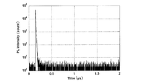
- 2 is a transient decay curve of a solution of Compound 1 of Example 1.
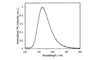
- 2 is an absorption emission spectrum of a solution of the compound 2 of Example 1.
- 2 is a transient decay curve of a solution of compound 2 of Example 1.
- 2 is an absorption emission spectrum of a solution of compound 3 of Example 1.
- 2 is a transient decay curve of a solution of the compound 3 of Example 1.
- 2 is an absorption emission spectrum of a solution of compound 4 of Example 1.
- 2 is a transient decay curve of a solution of compound 4 of Example 1.
- 2 is an absorption emission spectrum of a solution of compound 5 of Example 1.
- 2 is a transient decay curve of a solution of compound 5 of Example 1.
- 2 is an absorption emission spectrum of a solution of Compound A of Comparative Example 1.
- 2 is a transient decay curve of a solution of Compound A of Comparative Example 1.
- 2 is an emission spectrum of an organic photoluminescence device of Compound 1 of Example 2.
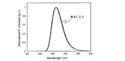
- 2 is an emission spectrum of an organic electroluminescence element of the compound 1 of Example 3.
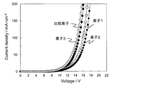
- 6 is a graph showing current density-voltage characteristics of the compound 1 of Example 3 and the Ir (ppy) 3 organic electroluminescence device of Comparative Example 2.
- FIG. 4 is a graph showing the current density-external quantum efficiency characteristics of the compound 1 of Example 3 and the Ir (ppy) 3 organic electroluminescent device of Comparative Example 2.
- a numerical range represented by using “to” means a range including numerical values described before and after “to” as a lower limit value and an upper limit value.
- the isotope species of the hydrogen atom present in the molecule of the compound used in the present invention is not particularly limited. For example, all the hydrogen atoms in the molecule may be 1 H, or a part or all of the hydrogen atoms are 2 H. (Deuterium D) may be used.
- Ar 1 represents a substituted or unsubstituted arylene group.
- the aromatic ring constituting the arylene group may be a single ring or a fused ring, and specific examples include a benzene ring, a naphthalene ring, an anthracene ring, and a phenanthrene ring.
- the arylene group preferably has 6 to 40 carbon atoms, more preferably 6 to 20 carbon atoms, and still more preferably 6 to 14 carbon atoms.
- arylene group examples include 1,4-phenylene group, 1,3-phenylene group, 1,2-phenylene group, 1,8-naphthylene group, 2,7-naphthylene group, 2,6-naphthylene group, , 4-naphthylene group, 1,3-naphthylene group, 9,10-anthracenylene group, 1,8-anthracenylene group, 2,7-anthracenylene group, 2,6-anthracenylene group, 1,4-anthracenylene group, 1, Examples include 3-anthracenylene group, 1,4-phenylene group, 1,3-phenylene group, 1,8-naphthylene group, 2,7-naphthylene group, 1,4-naphthylene group, 1,3-naphthylene. And the 9,10-anthracenylene group is preferred. Hydrogen atoms present in the structures of these specific examples may be substituted.
- Ar 2 and Ar 3 each independently represent a substituted or unsubstituted aryl group.
- the aromatic ring constituting the aryl group may be a single ring or a fused ring, and specific examples include a benzene ring, a naphthalene ring, an anthracene ring, and a phenanthrene ring.
- the aryl group preferably has 6 to 40 carbon atoms, more preferably 6 to 20 carbon atoms, and still more preferably 6 to 14 carbon atoms.
- aryl group examples include a phenyl group, a 1-naphthyl group, a 2-naphthyl group, a 1-anthracenyl group, a 2-anthracenyl group, and a 9-anthracenyl group.
- the phenyl group, the 1-naphthyl group, the 2- A naphthyl group is preferred.
- Hydrogen atoms present in the structures of these specific examples may be substituted.
- Ar 2 and Ar 3 in the general formula (1) may be the same or different. If they are the same, there is an advantage that synthesis is relatively easy.
- the arylene group of Ar 1 and the aryl groups of Ar 2 and Ar 3 may have a substituent or may be unsubstituted. When it has two or more substituents, the plurality of substituents may be the same as or different from each other.
- the substituent include a hydroxy group, a halogen atom, an alkyl group having 1 to 20 carbon atoms, an alkoxy group having 1 to 20 carbon atoms, an alkylthio group having 1 to 20 carbon atoms, an aryl group having 6 to 40 carbon atoms, and a carbon number.
- Examples thereof include 20 trialkylsilylalkyl groups, 5 to 20 trialkylsilylalkenyl groups, and 5 to 20 trialkylsilylalkynyl groups.
- those that can be substituted with a substituent may be further substituted.
- substituents are substituted or unsubstituted alkyl groups having 1 to 20 carbon atoms, alkoxy groups having 1 to 20 carbon atoms, substituted or unsubstituted aryl groups having 6 to 40 carbon atoms, and substituted groups having 3 to 40 carbon atoms. Or it is an unsubstituted heteroaryl group.
- Further preferred substituents are substituted or unsubstituted alkyl groups having 1 to 10 carbon atoms, substituted or unsubstituted alkoxy groups having 1 to 10 carbon atoms, substituted or unsubstituted aryl groups having 6 to 15 carbon atoms, 3 to 12 substituted or unsubstituted heteroaryl groups.
- the alkyl group may be linear, branched or cyclic, and more preferably has 1 to 6 carbon atoms. Specific examples include a methyl group, an ethyl group, a propyl group, a butyl group, and tert-butyl. Group, pentyl group, hexyl group and isopropyl group.
- the alkoxy group may be linear, branched or cyclic, and more preferably has 1 to 6 carbon atoms. Specific examples thereof include methoxy group, ethoxy group, propoxy group, butoxy group, tert-butoxy group. A group, a pentyloxy group, a hexyloxy group, and an isopropyloxy group.
- the aryl group that can be employed as the substituent may be a single ring or a condensed ring, and specific examples thereof include a phenyl group and a naphthyl group.
- the heteroaryl group may be a single ring or a condensed ring, and specific examples thereof include a pyridyl group, a pyridazyl group, a pyrimidyl group, a triazyl group, a triazolyl group, and a benzotriazolyl group.
- These heteroaryl groups may be a group bonded through a hetero atom or a group bonded through a carbon atom constituting a heteroaryl ring.
- R 1 to R 8 each independently represents a hydrogen atom or a substituent. However, at least one of R 1 to R 8 is a substituted or unsubstituted diarylamino group.
- the two aryl groups in the diarylamino group here may be the same or different, but are preferably the same.
- the above description of the aryl group of Ar 2 and Ar 3 can be referred to.
- Two aryl groups of the diarylamino group may be linked to each other. By linking each other, for example, a carbazole ring can be formed.
- diarylamino group examples include a diphenylamino group, a di (1-naphthyl) amino group, a di (2-naphthyl) amino group, a di (4-methylphenyl) amino group, a di (3-methylphenyl) amino group, Examples thereof include a di (3,5-dimethylphenyl) amino group, a di (4-biphenyl) amino group, and a 9-carbazolyl group.
- R 1 to R 8 is required to be a substituted or unsubstituted diarylamino group.
- 1 to 4 of R 1 to R 8 are substituted or unsubstituted diarylamino groups, and more preferably 2 to 4 are substituted or unsubstituted diarylamino groups.
- the plurality of substituted or unsubstituted diarylamino groups may be the same as or different from each other.
- At least one of R 1 to R 4 is a substituted or unsubstituted diarylamino group, and at least one of R 5 to R 8 is a substituted or unsubstituted diarylamino group It is preferable that Among them, it is preferable that at least R 3 and R 6 are substituted or unsubstituted diarylamino groups.
- Examples of the substituent for the diarylamino group include a hydroxy group, a halogen atom, a cyano group, an alkyl group having 1 to 20 carbon atoms, an alkoxy group having 1 to 20 carbon atoms, an alkylthio group having 1 to 20 carbon atoms, and 1 to 20 alkyl-substituted amino groups, aryl substituted amino groups having 12 to 40 carbon atoms, acyl groups having 2 to 20 carbon atoms, aryl groups having 6 to 40 carbon atoms, heteroaryl groups having 3 to 40 carbon atoms, 12 to 12 carbon atoms 40 substituted or unsubstituted carbazolyl groups, alkenyl groups having 2 to 10 carbon atoms, alkynyl groups having 2 to 10 carbon atoms, alkoxycarbonyl groups having 2 to 10 carbon atoms, alkylsulfonyl groups having 1 to 10 carbon atoms, carbon numbers 1-10 haloalkyl group, amide group, C2-
- substituents are a halogen atom, a cyano group, a substituted or unsubstituted alkyl group having 1 to 20 carbon atoms, an alkoxy group having 1 to 20 carbon atoms, a substituted or unsubstituted aryl group having 6 to 40 carbon atoms, carbon A substituted or unsubstituted heteroaryl group having 3 to 40 carbon atoms, a substituted or unsubstituted dialkylamino group having 1 to 10 carbon atoms, a substituted or unsubstituted diarylamino group having 12 to 40 carbon atoms, and 12 to 40 carbon atoms A substituted or unsubstituted carbazolyl group; More preferred substituents are a fluorine atom, a chlorine atom, a cyano group, a substituted or unsubstituted alkyl group having 1 to 10 carbon atoms
- an unsubstituted dialkylamino group a substituted or unsubstituted diarylamino group having 12 to 40 carbon atoms, a substituted or unsubstituted aryl group having 6 to 15 carbon atoms, and a substituted or unsubstituted heteroaryl group having 3 to 12 carbon atoms It is a group.
- All of R 1 to R 8 other than the substituted or unsubstituted diarylamino group may be a hydrogen atom, or any one or more of them may be a substituent.
- the plurality of substituents may be the same as or different from each other. Examples of such substituents include hydroxy groups, halogen atoms, cyano groups, alkyl groups having 1 to 20 carbon atoms, alkoxy groups having 1 to 20 carbon atoms, alkylthio groups having 1 to 20 carbon atoms, and 1 to 20 carbon atoms.
- Alkyl-substituted amino group acyl group having 2 to 20 carbon atoms, aryl group having 6 to 40 carbon atoms, heteroaryl group having 3 to 40 carbon atoms, alkenyl group having 2 to 10 carbon atoms, alkynyl group having 2 to 10 carbon atoms An alkoxycarbonyl group having 2 to 10 carbon atoms, an alkylsulfonyl group having 1 to 10 carbon atoms, a haloalkyl group having 1 to 10 carbon atoms, an amide group, an alkylamide group having 2 to 10 carbon atoms, and a tricarbon having 3 to 20 carbon atoms.
- those that can be substituted with a substituent may be further substituted.
- More preferred substituents are a halogen atom, a cyano group, a substituted or unsubstituted alkyl group having 1 to 20 carbon atoms, an alkoxy group having 1 to 20 carbon atoms, a substituted or unsubstituted aryl group having 6 to 40 carbon atoms, carbon A substituted or unsubstituted heteroaryl group having 3 to 40 carbon atoms, and a dialkyl-substituted amino group having 1 to 20 carbon atoms.
- substituents are a fluorine atom, a chlorine atom, a cyano group, a substituted or unsubstituted alkyl group having 1 to 10 carbon atoms, a substituted or unsubstituted alkoxy group having 1 to 10 carbon atoms, and a substituted group having 6 to 15 carbon atoms.
- it is an unsubstituted aryl group or a substituted or unsubstituted heteroaryl group having 3 to 12 carbon atoms.
- R 1 and R 2 , R 2 and R 3 , R 3 and R 4 , R 5 and R 6 , R 6 and R 7 , R 7 and R 8 are bonded to each other to form a cyclic structure May be formed.
- the cyclic structure may be an aromatic ring or an alicyclic ring, may contain a hetero atom, and the cyclic structure may be a condensed ring of two or more rings.
- the hetero atom here is preferably selected from the group consisting of a nitrogen atom, an oxygen atom and a sulfur atom.
- Examples of cyclic structures formed include benzene ring, naphthalene ring, pyridine ring, pyridazine ring, pyrimidine ring, pyrazine ring, pyrrole ring, imidazole ring, pyrazole ring, triazole ring, imidazoline ring, oxazole ring, isoxazole ring, thiazole And a ring, an isothiazole ring, a cyclohexadiene ring, a cyclohexene ring, a cyclopentaene ring, a cycloheptatriene ring, a cycloheptadiene ring, and a cycloheptaene ring.
- the compound represented by the general formula (1) preferably has a structure represented by the following general formula (2).
- R 1 to R 8 and R 11 to R 24 each independently represent a hydrogen atom or a substituent, and at least one of R 1 to R 8 is a substituted or unsubstituted diarylamino group. is there.
- the substituted or unsubstituted diarylamino group, the substituents that R 1 to R 8 can take, and the substituents that R 11 to R 24 can take are substituted or unsubstituted diarylamino groups of the general formula (1), R 1 Reference can be made to explanations and preferred ranges of the substituents that can be taken by —R 8 and the substituents that can be taken by the aryl groups of Ar 1 to Ar 3 .
- R 13 , R 13 and R 14 , R 14 and R 15 , R 16 and R 17 , R 17 and R 18 , R 18 and R 19 , R 19 and R 20 , R 21 and R 22 , R 23 and R 24 may be bonded to each other to form a ring structure.
- the corresponding description in the general formula (1) can be referred to.
- At least one of R 1 to R 4 is a substituted or unsubstituted diarylamino group, and at least one of R 5 to R 8 is substituted or unsubstituted.
- a compound group that is a diarylamino group and a compound group in which R 3 and R 6 are substituted or unsubstituted diarylamino groups can be exemplified.
- the molecular weight of the compound represented by the general formula (1) is, for example, 1500 or less when the organic layer containing the compound represented by the general formula (1) is intended to be formed by vapor deposition. Preferably, it is preferably 1200 or less, more preferably 1000 or less, and even more preferably 800 or less.
- the lower limit of the molecular weight is the molecular weight of the minimum compound represented by the general formula (1).
- the compound represented by the general formula (1) may be formed by a coating method regardless of the molecular weight. If a coating method is used, a film can be formed even with a compound having a relatively large molecular weight.
- a compound containing a plurality of structures represented by the general formula (1) in the molecule as a light emitting material.
- a polymer obtained by previously polymerizing a polymerizable group in the structure represented by the general formula (1) and polymerizing the polymerizable group as a light emitting material.
- a monomer containing a polymerizable functional group is prepared in any one of Ar 1 to Ar 3 and R 1 to R 8 in the general formula (1), and this is polymerized alone or together with other monomers.
- a polymer having repeating units by copolymerization and use the polymer as a light emitting material it is also possible to obtain a dimer or trimer by coupling compounds having a structure represented by the general formula (1) and use them as a light emitting material.
- polymer having a repeating unit including the structure represented by the general formula (1) a polymer including a structure represented by the following general formula (3) or (4) can be given.
- Q represents a group including the structure represented by the general formula (1)
- L 1 and L 2 represent a linking group.
- the linking group preferably has 0 to 20 carbon atoms, more preferably 1 to 15 carbon atoms, and still more preferably 2 to 10 carbon atoms. And preferably has a structure represented by - linking group -X 11 -L 11.
- X 11 represents an oxygen atom or a sulfur atom, and is preferably an oxygen atom.
- L 11 represents a linking group, and is preferably a substituted or unsubstituted alkylene group, or a substituted or unsubstituted arylene group, and is a substituted or unsubstituted alkylene group having 1 to 10 carbon atoms, or a substituted or unsubstituted group A phenylene group is more preferable.
- R 101 , R 102 , R 103 and R 104 each independently represent a substituent.
- it is a substituted or unsubstituted alkyl group having 1 to 6 carbon atoms, a substituted or unsubstituted alkoxy group having 1 to 6 carbon atoms, or a halogen atom, more preferably an unsubstituted alkyl group having 1 to 3 carbon atoms.
- An unsubstituted alkoxy group having 1 to 3 carbon atoms, a fluorine atom, and a chlorine atom and more preferably an unsubstituted alkyl group having 1 to 3 carbon atoms and an unsubstituted alkoxy group having 1 to 3 carbon atoms.
- Linking group represented by L 1 and L 2 are either Ar 1 of the structure of the general formula (1) ⁇ Ar 3, R 1 ⁇ R 8 constituting the Q, R 1 of the structure of the general formula (2) Can be bonded to any one of -R 8 and R 11 -R 24 .
- Two or more linking groups may be linked to one Q to form a crosslinked structure or a network structure.
- repeating unit examples include structures represented by the following formulas (5) to (8).
- the polymer having a repeating unit containing these formulas (5) to (8) has a hydroxy group introduced into any of Ar 1 to Ar 3 and R 1 to R 8 in the structure of the general formula (1). Then, it can be synthesized by reacting the following compound as a linker to introduce a polymerizable group and polymerizing the polymerizable group.
- the polymer containing a structure represented by the general formula (1) in the molecule may be a polymer consisting only of a repeating unit having the structure represented by the general formula (1), or other structures may be used. It may be a polymer containing repeating units.
- the repeating unit having a structure represented by the general formula (1) contained in the polymer may be a single type or two or more types. Examples of the repeating unit not having the structure represented by the general formula (1) include those derived from monomers used in ordinary copolymerization. Examples thereof include a repeating unit derived from a monomer having an ethylenically unsaturated bond such as ethylene and styrene.
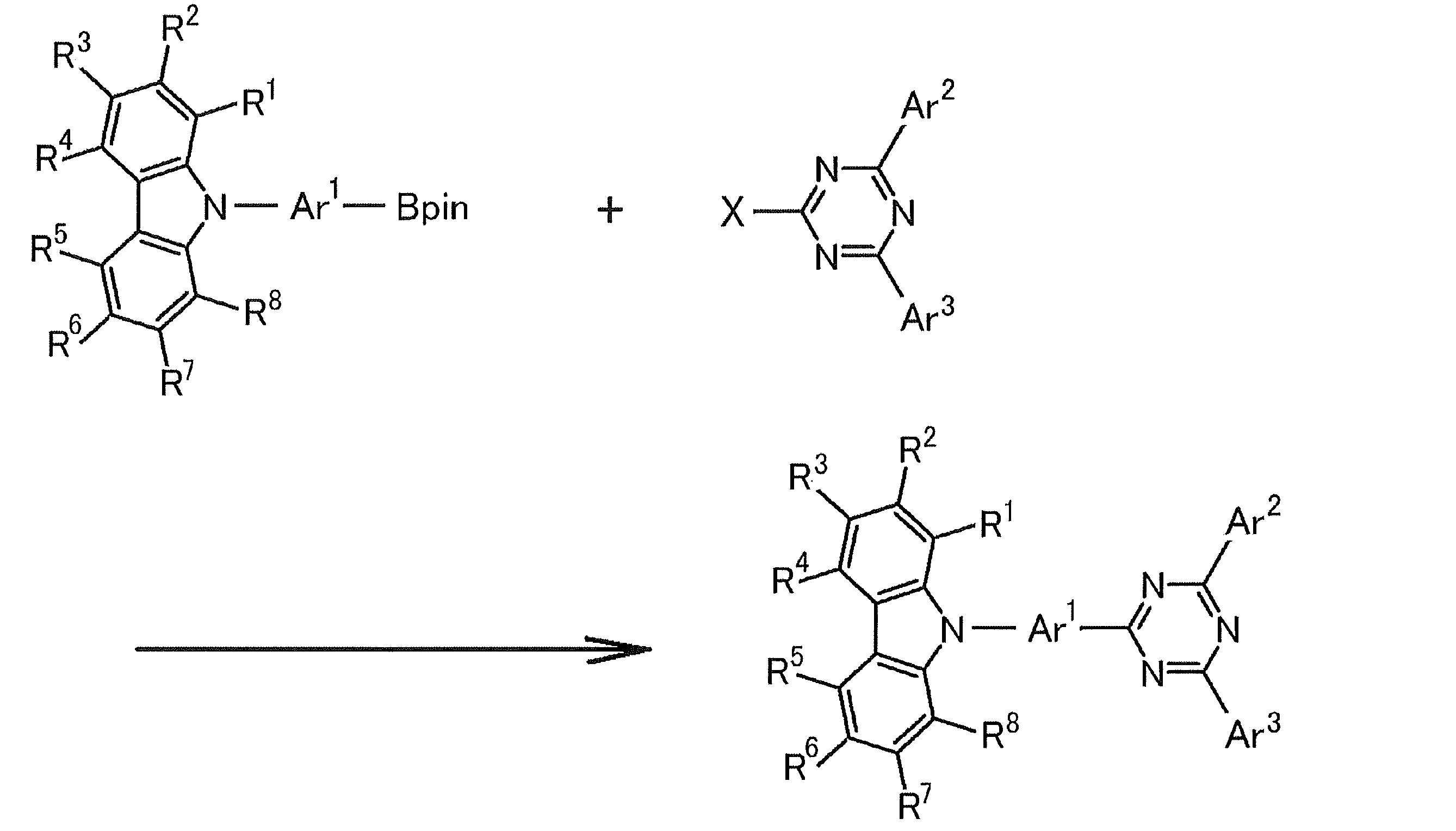
- the compound represented by the general formula (1) can be synthesized by combining known reactions. For example, it can be synthesized according to the following scheme.
- Pin in the above formula represents a pinacolato group.
- X represents a halogen atom, and examples thereof include a fluorine atom, a chlorine atom, a bromine atom, and an iodine atom, and a chlorine atom and a bromine atom are preferable.
- the reaction in the above scheme is an application of a known coupling reaction, and known reaction conditions can be appropriately selected and used.
- the carbazole derivative as a starting material can be synthesized using a known synthesis method in which a corresponding bromide is reacted with bis (pinacolato) diboron.
- the details of the above reaction and synthesis route can be referred to the synthesis examples described later.
- the compound represented by the general formula (1) can also be synthesized by combining other known synthesis reactions.
- the compound represented by the general formula (1) of the present invention is useful as a light emitting material of an organic light emitting device. For this reason, the compound represented by General formula (1) of this invention can be effectively used as a luminescent material for the light emitting layer of an organic light emitting element.
- the compound represented by the general formula (1) includes a delayed fluorescent material (delayed phosphor) that emits delayed fluorescence. That is, the present invention relates to a delayed phosphor having a structure represented by the general formula (1), an invention using a compound represented by the general formula (1) as a delayed phosphor, and a general formula (1).
- An invention of a method for emitting delayed fluorescence using the represented compound is also provided.
- An organic light emitting device using such a compound as a light emitting material emits delayed fluorescence and has a feature of high luminous efficiency. The principle will be described below by taking an organic electroluminescence element as an example.
- the organic electroluminescence element carriers are injected into the light emitting material from both positive and negative electrodes to generate an excited light emitting material and emit light.
- 25% of the generated excitons are excited to the excited singlet state, and the remaining 75% are excited to the excited triplet state. Therefore, the use efficiency of energy is higher when phosphorescence, which is light emission from an excited triplet state, is used.
- the excited triplet state has a long lifetime, energy saturation occurs due to saturation of the excited state and interaction with excitons in the excited triplet state, and in general, the quantum yield of phosphorescence is often not high.
- delayed fluorescent materials after energy transition to an excited triplet state due to intersystem crossing, etc., are then crossed back to an excited singlet state due to triplet-triplet annihilation or absorption of thermal energy, and emit fluorescence.
- a thermally activated delayed fluorescent material by absorption of thermal energy is particularly useful.
- excitons in the excited singlet state emit fluorescence as usual.
- excitons in the excited triplet state absorb heat generated by the device and cross between the excited singlets to emit fluorescence.
- the light is emitted from the excited singlet, the light is emitted at the same wavelength as the fluorescence, but the light lifetime (luminescence lifetime) generated by the reverse intersystem crossing from the excited triplet state to the excited singlet state is normal. Since the fluorescence becomes longer than the fluorescence and phosphorescence, it is observed as fluorescence delayed from these. This can be defined as delayed fluorescence. If such a heat-activated exciton transfer mechanism is used, the ratio of the compound in an excited singlet state, which normally generated only 25%, is increased to 25% or more by absorbing thermal energy after carrier injection. It can be raised.
- the heat of the device will sufficiently cause intersystem crossing from the excited triplet state to the excited singlet state and emit delayed fluorescence. Efficiency can be improved dramatically.
- the compound represented by the general formula (1) of the present invention as a light-emitting material of a light-emitting layer, excellent organic light-emitting devices such as an organic photoluminescence device (organic PL device) and an organic electroluminescence device (organic EL device) Can be provided.
- the compound represented by the general formula (1) of the present invention may have a function of assisting light emission of another light emitting material included in the light emitting layer as a so-called assist dopant. That is, the compound represented by the general formula (1) of the present invention contained in the light emitting layer includes the lowest excitation singlet energy level of the host material contained in the light emitting layer and the lowest excitation of other light emitting materials contained in the light emitting layer.
- the organic photoluminescence element has a structure in which at least a light emitting layer is formed on a substrate.
- the organic electroluminescence element has a structure in which an organic layer is formed at least between an anode, a cathode, and an anode and a cathode.
- the organic layer includes at least a light emitting layer, and may consist of only the light emitting layer, or may have one or more organic layers in addition to the light emitting layer. Examples of such other organic layers include a hole transport layer, a hole injection layer, an electron blocking layer, a hole blocking layer, an electron injection layer, an electron transport layer, and an exciton blocking layer.
- the hole transport layer may be a hole injection / transport layer having a hole injection function
- the electron transport layer may be an electron injection / transport layer having an electron injection function.
- FIG. 1 A specific example of the structure of an organic electroluminescence element is shown in FIG.
- 1 is a substrate
- 2 is an anode
- 3 is a hole injection layer
- 4 is a hole transport layer
- 5 is a light emitting layer
- 6 is an electron transport layer
- 7 is a cathode.
- each member and each layer of an organic electroluminescent element are demonstrated.
- substrate and a light emitting layer corresponds also to the board
- the organic electroluminescence device of the present invention is preferably supported on a substrate.
- the substrate is not particularly limited and may be any substrate conventionally used for organic electroluminescence elements.
- a substrate made of glass, transparent plastic, quartz, silicon, or the like can be used.
- an electrode material made of a metal, an alloy, an electrically conductive compound, or a mixture thereof having a high work function (4 eV or more) is preferably used.
- electrode materials include metals such as Au, and conductive transparent materials such as CuI, indium tin oxide (ITO), SnO 2 and ZnO.
- conductive transparent materials such as CuI, indium tin oxide (ITO), SnO 2 and ZnO.
- an amorphous material such as IDIXO (In 2 O 3 —ZnO) capable of forming a transparent conductive film may be used.
- a thin film may be formed by vapor deposition or sputtering of these electrode materials, and a pattern of a desired shape may be formed by photolithography, or when pattern accuracy is not so high (about 100 ⁇ m or more) ), A pattern may be formed through a mask having a desired shape at the time of vapor deposition or sputtering of the electrode material.
- wet film-forming methods such as a printing system and a coating system, can also be used.
- the transmittance be greater than 10%, and the sheet resistance as the anode is preferably several hundred ⁇ / ⁇ or less.
- the film thickness depends on the material, it is usually selected in the range of 10 to 1000 nm, preferably 10 to 200 nm.
- cathode a material having a low work function (4 eV or less) metal (referred to as an electron injecting metal), an alloy, an electrically conductive compound, and a mixture thereof as an electrode material is used.
- electrode materials include sodium, sodium-potassium alloy, magnesium, lithium, magnesium / copper mixture, magnesium / silver mixture, magnesium / aluminum mixture, magnesium / indium mixture, aluminum / aluminum oxide (Al 2 O 3 ) Mixtures, indium, lithium / aluminum mixtures, rare earth metals and the like.
- a mixture of an electron injecting metal and a second metal which is a stable metal having a larger work function value than this for example, a magnesium / silver mixture, Magnesium / aluminum mixtures, magnesium / indium mixtures, aluminum / aluminum oxide (Al 2 O 3 ) mixtures, lithium / aluminum mixtures, aluminum and the like are preferred.
- the cathode can be produced by forming a thin film of these electrode materials by a method such as vapor deposition or sputtering.
- the sheet resistance as the cathode is preferably several hundred ⁇ / ⁇ or less, and the film thickness is usually selected in the range of 10 nm to 5 ⁇ m, preferably 50 to 200 nm.
- the emission luminance is advantageously improved.
- a transparent or semi-transparent cathode can be produced. By applying this, an element in which both the anode and the cathode are transparent is used. Can be produced.
- the light emitting layer is a layer that emits light after excitons are generated by recombination of holes and electrons injected from each of the anode and the cathode, and the light emitting material may be used alone for the light emitting layer. , Preferably including a luminescent material and a host material.
- a luminescent material the 1 type (s) or 2 or more types chosen from the compound group of this invention represented by General formula (1) can be used.
- a host material in addition to the light emitting material in the light emitting layer.
- the host material an organic compound having at least one of excited singlet energy and excited triplet energy higher than that of the light emitting material of the present invention can be used.
- singlet excitons and triplet excitons generated in the light emitting material of the present invention can be confined in the molecules of the light emitting material of the present invention, and the light emission efficiency can be sufficiently extracted.
- high luminous efficiency can be obtained, so that host materials that can achieve high luminous efficiency are particularly limited. And can be used in the present invention.
- the organic light emitting device or organic electroluminescent device of the present invention light emission is generated from the light emitting material of the present invention contained in the light emitting layer. This emission includes both fluorescence and delayed fluorescence. However, light emission from the host material may be partly or partly emitted.
- the amount of the compound of the present invention, which is a light emitting material is preferably 0.1% by weight or more, more preferably 1% by weight or more, and 50% or more. It is preferably no greater than wt%, more preferably no greater than 20 wt%, and even more preferably no greater than 10 wt%.
- the host material in the light-emitting layer is preferably an organic compound that has a hole transporting ability and an electron transporting ability, prevents the emission of longer wavelengths, and has a high glass transition temperature.
- the injection layer is a layer provided between the electrode and the organic layer for lowering the driving voltage and improving the luminance of light emission.
- the injection layer can be provided as necessary.
- the blocking layer is a layer that can prevent diffusion of charges (electrons or holes) and / or excitons existing in the light emitting layer to the outside of the light emitting layer.
- the electron blocking layer can be disposed between the light emitting layer and the hole transport layer and blocks electrons from passing through the light emitting layer toward the hole transport layer.
- a hole blocking layer can be disposed between the light emitting layer and the electron transporting layer to prevent holes from passing through the light emitting layer toward the electron transporting layer.
- the blocking layer can also be used to block excitons from diffusing outside the light emitting layer. That is, each of the electron blocking layer and the hole blocking layer can also function as an exciton blocking layer.
- the term “electron blocking layer” or “exciton blocking layer” as used herein is used in the sense of including a layer having the functions of an electron blocking layer and an exciton blocking layer in one layer.
- the hole blocking layer has a function of an electron transport layer in a broad sense.
- the hole blocking layer has a role of blocking holes from reaching the electron transport layer while transporting electrons, thereby improving the recombination probability of electrons and holes in the light emitting layer.
- the material for the hole blocking layer the material for the electron transport layer described later can be used as necessary.
- the electron blocking layer has a function of transporting holes in a broad sense.
- the electron blocking layer has a role to block electrons from reaching the hole transport layer while transporting holes, thereby improving the probability of recombination of electrons and holes in the light emitting layer. .
- the exciton blocking layer is a layer for preventing excitons generated by recombination of holes and electrons in the light emitting layer from diffusing into the charge transport layer. It becomes possible to efficiently confine in the light emitting layer, and the light emission efficiency of the device can be improved.
- the exciton blocking layer can be inserted on either the anode side or the cathode side adjacent to the light emitting layer, or both can be inserted simultaneously.
- the layer when the exciton blocking layer is provided on the anode side, the layer can be inserted adjacent to the light emitting layer between the hole transport layer and the light emitting layer, and when inserted on the cathode side, the light emitting layer and the cathode Between the luminescent layer and the light-emitting layer.
- a hole injection layer, an electron blocking layer, or the like can be provided between the anode and the exciton blocking layer adjacent to the anode side of the light emitting layer, and the excitation adjacent to the cathode and the cathode side of the light emitting layer can be provided.
- an electron injection layer, an electron transport layer, a hole blocking layer, and the like can be provided.
- the blocking layer is disposed, at least one of the excited singlet energy and the excited triplet energy of the material used as the blocking layer is preferably higher than the excited singlet energy and the excited triplet energy of the light emitting material.
- the hole transport layer is made of a hole transport material having a function of transporting holes, and the hole transport layer can be provided as a single layer or a plurality of layers.
- the hole transport material has any one of hole injection or transport and electron barrier properties, and may be either organic or inorganic.
- hole transport materials that can be used include, for example, triazole derivatives, oxadiazole derivatives, imidazole derivatives, carbazole derivatives, indolocarbazole derivatives, polyarylalkane derivatives, pyrazoline derivatives and pyrazolone derivatives, phenylenediamine derivatives, arylamine derivatives, Examples include amino-substituted chalcone derivatives, oxazole derivatives, styrylanthracene derivatives, fluorenone derivatives, hydrazone derivatives, stilbene derivatives, silazane derivatives, aniline copolymers, and conductive polymer oligomers, particularly thiophene oligomers.
- An aromatic tertiary amine compound and an styrylamine compound are preferably used, and an aromatic tertiary amine compound is more preferably used.
- the electron transport layer is made of a material having a function of transporting electrons, and the electron transport layer can be provided as a single layer or a plurality of layers.
- the electron transport material (which may also serve as a hole blocking material) may have a function of transmitting electrons injected from the cathode to the light emitting layer.
- Examples of the electron transport layer that can be used include nitro-substituted fluorene derivatives, diphenylquinone derivatives, thiopyran dioxide oxide derivatives, carbodiimides, fluorenylidenemethane derivatives, anthraquinodimethane and anthrone derivatives, oxadiazole derivatives, and the like.
- a thiadiazole derivative in which the oxygen atom of the oxadiazole ring is substituted with a sulfur atom, and a quinoxaline derivative having a quinoxaline ring known as an electron withdrawing group can also be used as an electron transport material.
- a polymer material in which these materials are introduced into a polymer chain or these materials are used as a polymer main chain can also be used.
- the compound represented by the general formula (1) may be used not only for the light emitting layer but also for layers other than the light emitting layer.
- the compound represented by General formula (1) used for a light emitting layer and the compound represented by General formula (1) used for layers other than a light emitting layer may be same or different.
- the compound represented by the general formula (1) may be used for the injection layer, blocking layer, hole blocking layer, electron blocking layer, exciton blocking layer, hole transporting layer, electron transporting layer, and the like. .
- the method for forming these layers is not particularly limited, and the layer may be formed by either a dry process or a wet process.
- the preferable material which can be used for an organic electroluminescent element is illustrated concretely.
- the material that can be used in the present invention is not limited to the following exemplary compounds.
- R and R 1 to R 10 in the structural formulas of the following exemplary compounds each independently represent a hydrogen atom or a substituent.
- n represents an integer of 3 to 5.
- the organic electroluminescence device produced by the above-described method emits light by applying an electric field between the anode and the cathode of the obtained device. At this time, if the light is emitted by excited singlet energy, light having a wavelength corresponding to the energy level is confirmed as fluorescence emission and delayed fluorescence emission. In addition, in the case of light emission by excited triplet energy, a wavelength corresponding to the energy level is confirmed as phosphorescence. Since normal fluorescence has a shorter fluorescence lifetime than delayed fluorescence, the emission lifetime can be distinguished from fluorescence and delayed fluorescence.
- the excited triplet energy is unstable and is converted into heat and the like, and the lifetime is short and it is immediately deactivated.
- the excited triplet energy of a normal organic compound it can be measured by observing light emission under extremely low temperature conditions.
- the organic electroluminescence element of the present invention can be applied to any of a single element, an element having a structure arranged in an array, and a structure in which an anode and a cathode are arranged in an XY matrix.
- an organic light emitting device with greatly improved light emission efficiency can be obtained by containing the compound represented by the general formula (1) in the light emitting layer.
- the organic light emitting device such as the organic electroluminescence device of the present invention can be further applied to various uses. For example, it is possible to produce an organic electroluminescence display device using the organic electroluminescence element of the present invention. For details, see “Organic EL Display” (Ohm Co., Ltd.) ) Can be referred to.
- the organic electroluminescence device of the present invention can be applied to organic electroluminescence illumination and backlights that are in great demand.
- source meter manufactured by Keithley: 2400 series
- semiconductor parameter analyzer manufactured by Agilent Technologies: E5273A
- optical power meter measuring device manufactured by Newport: 1930C
- optical spectrometer Ocean Optics, USB2000
- spectroradiometer Topcon, SR-3
- streak camera Haamamatsu Photonics C4334
- Carbazole (intermediate 1) (25.7 g, 150 mmol: manufactured by Nacalai Tesque), benzyl chloride (58.4 g, 454.5 mmol: manufactured by Wako Pure Chemical Industries, Ltd.) and potassium hydroxide (41.1 g, A solution of 714.3 mmol: manufactured by Nacalai Tesque Co., Ltd. in tetrahydrofuran (250 mL: manufactured by Kanto Chemical Co., Ltd.) was refluxed for 34 hours under an argon atmosphere. Next, after standing to cool at room temperature, water (250 mL) and dichloromethane (200 mL) were added to the reaction solution to separate the layers.
- Tetrahydrofuran (15 mL) is added to magnesium (4.1 g, 172.8 mmol: manufactured by Wako Pure Chemical Industries, Ltd.), and dibromoethane (0.29 g, 0.0015 mmol: manufactured by Wako Pure Chemical Industries, Ltd.) is stirred.
- Bromobenzene (26.2 g, 166.8 mmol: manufactured by Nacalai Tesque) was added dropwise thereto at room temperature, and then refluxed for 3 hours in an argon atmosphere.
- Tricyclohexylphosphine (0.053 g, 0.19 mmol: manufactured by strem chemicals), tris (dibenzylideneacetone) (chloroform) palladium (0) (0.043 g, 0.041 mmol) 1,4-dioxane (15 mL: Wako Pure Chemicals) Kogyo Co., Ltd. solution was stirred at room temperature for 30 minutes.
- the reaction mixture was diluted with dichloromethane and passed through a silica gel column. This solution was distilled off with an evaporator, and the residue was purified by silica gel column chromatography (dichloromethane 20%, hexane 80%) and then recrystallized twice from a mixed solvent of dichloromethane and hexane to obtain Compound 1 as yellow crystals. (0.98 g). Further, the crystals were purified by sublimation to obtain Compound 1 as a yellow solid (0.70 g).
- intermediate 12 (1.20 g, 1.79 mmol) was dissolved in cyclopentyl methyl ether (17 mL: manufactured by Wako Pure Chemical Industries, Ltd.) and cooled to 0 ° C. To this was added dropwise a hexane solution of n-bryllithium (1.6 M, 1.23 mL, 1.97 mmol: manufactured by Wako Pure Chemical Industries, Ltd.), and the mixture was stirred at 0 ° C. for 1.5 hours. To this solution, tributyltin chloride (699 mg, 2.15 mmol: manufactured by Sigma-Aldrich) was added dropwise and stirred for 10 hours at room temperature.
- reaction mixture was diluted with dichloromethane and passed through a silica gel column. This solution was distilled off with an evaporator, and the residue was purified by silica gel column chromatography (dichloromethane 20%, hexane 80%) and then recrystallized from a mixed solvent of dichloromethane and hexane to obtain Compound 2 as yellow crystals (0 .90 g, 61%).
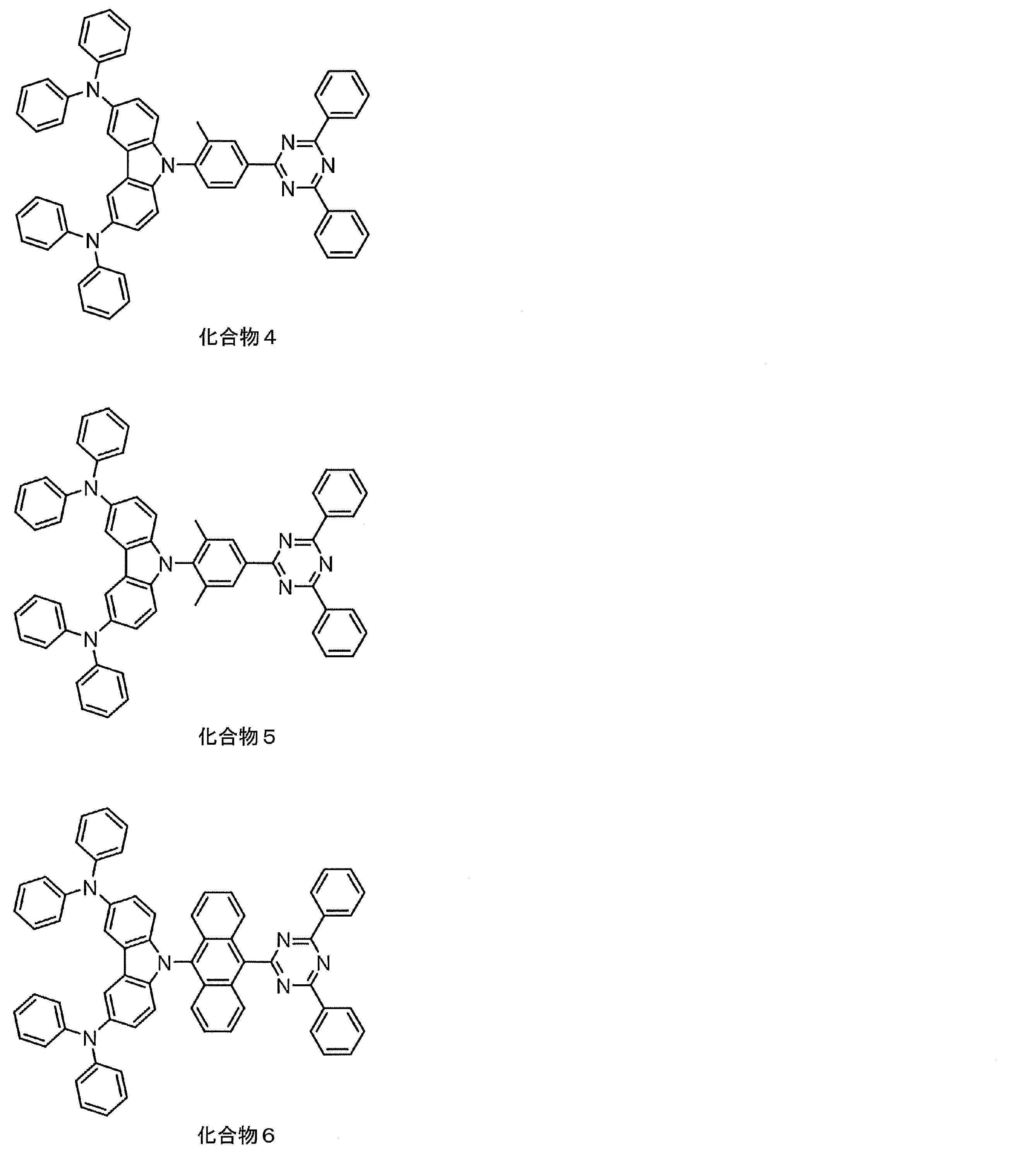
- intermediate 6 (1.20 g, 2.40 mmol), 2-bromo-5-iodo-1,3-dimethylbenzene (intermediate 15) (893 mg, 2.88 mmol), L-proline (110 mg, 0.96 mmol: manufactured by Wako Pure Chemical Industries, Ltd.), potassium carbonate (1.68 g, 4.80 mmol: manufactured by Wako Pure Chemical Industries, Ltd.) and copper iodide (91.4 mg, 0.48 mmol: Wako Pure Chemical Industries, Ltd.) A suspension of dimethylformamide (2.4 mL: manufactured by Wako Pure Chemical Industries, Ltd.) was heated to 110 ° C. for 48 hours under an argon atmosphere.
- reaction mixture was diluted with dichloromethane and passed through a silica gel column. This solution was distilled off with an evaporator, and the residue was purified by silica gel column chromatography (dichloromethane 20%, hexane 80%) and then recrystallized from a mixed solvent of dichloromethane and hexane to obtain compound 3 as yellow crystals (0 .87 g, 58%).
- reaction mixture was diluted with dichloromethane and passed through a silica gel column. This solution was distilled off with an evaporator, and the residue was purified by silica gel column chromatography (dichloromethane 20%, hexane 80%) and then recrystallized from a mixed solvent of dichloromethane and hexane to obtain compound 5 as yellow crystals (0 .88 g, 60%).
- Example 1 Preparation and evaluation of organic photoluminescence device (solution)
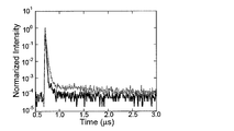
- This transient decay curve shows the result of measuring the luminescence lifetime obtained by measuring the process in which the emission intensity is deactivated by applying excitation light to the compound.
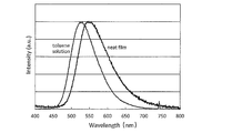
- FIG. 4 shows the results of preparing a toluene solution of compound 2 (concentration 10 ⁇ 5 mol / L) and measuring the absorption emission spectrum.
- FIG. 5 shows a transient decay curve of the peak emission wavelength measured under the conditions without Ar bubbling and with Ar bubbling. Delayed fluorescence was observed in the measurement under conditions with Ar bubbling.
- the photoluminescence quantum yield was 47% without Ar bubbling and 84% with Ar bubbling.
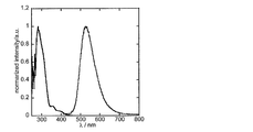
- FIG. 6 shows the results of preparing a toluene solution of compound 3 (concentration 10 ⁇ 5 mol / L) and measuring the absorption emission spectrum.
- FIG. 4 shows the results of preparing a toluene solution of compound 2 (concentration 10 ⁇ 5 mol / L) and measuring the absorption emission spectrum.
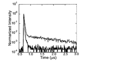
- FIG. 5 shows a transient decay curve of the peak emission wavelength measured under the conditions without Ar bubbling and with Ar bubbling. Delayed fluorescence was observed in the measurement under conditions with Ar bubbling.
- FIG. 7 shows a transient decay curve of the peak emission wavelength measured under the conditions without Ar bubbling and with Ar bubbling. Delayed fluorescence was observed in the measurement under conditions with Ar bubbling. The photoluminescence quantum yield was 11% without Ar bubbling and 42% with Ar bubbling.
- FIG. 8 shows the results of preparing a toluene solution of compound 4 (concentration 10 ⁇ 5 mol / L) and measuring the absorption emission spectrum.
- FIG. 9 shows a transient attenuation curve of the peak emission wavelength measured under the conditions without Ar bubbling and with Ar bubbling. Delayed fluorescence was observed in the measurement under conditions with Ar bubbling. The photoluminescence quantum yield was 31% without Ar bubbling and 60% with Ar bubbling.
- FIG. 8 shows the results of preparing a toluene solution of compound 4 (concentration 10 ⁇ 5 mol / L) and measuring the absorption emission spectrum.
- FIG. 9 shows a transient attenuation curve of the peak emission wavelength measured under the conditions without Ar
- FIG. 10 shows the results of preparing a toluene solution of compound 5 (concentration 10 ⁇ 5 mol / L) and measuring the absorption emission spectrum. Further, FIG. 11 shows a transient attenuation curve of the peak emission wavelength measured under the conditions without Ar bubbling and with Ar bubbling. Delayed fluorescence was observed in the measurement under conditions with Ar bubbling. The photoluminescence quantum yield was 15% without Ar bubbling and 53% with Ar bubbling.
- Example 1 A toluene solution was prepared in the same manner as in Example 1, except that the following compound A was used instead of compound 1.
- the absorption emission spectrum is shown in FIG.
- the transient attenuation curve obtained on the same conditions as Example 1 is shown in FIG. No delayed fluorescence was observed.
- Example 2 Preparation and evaluation of organic photoluminescence device (thin film)
- a thin film of Compound 1 was formed to a thickness of 50 nm on a quartz substrate by a vacuum deposition method under a vacuum degree of 10 ⁇ 4 Pa or less to obtain an organic photoluminescence device.
- FIG. 2 shows the result of measuring the emission spectrum of 330 nm excitation light for the produced organic photoluminescence device.
- Compound 1 and CBP were vapor-deposited from a different vapor deposition source on a quartz substrate by a vacuum vapor deposition method under a vacuum degree of 10 ⁇ 4 Pa or less, and a thin film having a concentration of compound 1 of 6.0% by weight of 100 nm was formed.
- the organic photoluminescence element was formed with a thickness.
- FIG. 14 shows the result of measuring the emission spectrum of 330 nm excitation light for the produced organic photoluminescence device.
- Example 3 indium-tin oxide Preparation and Evaluation thickness 50nm of the organic electroluminescent element on a glass substrate with the anode formed consisting of (ITO), by vacuum deposition of each thin film, the vacuum degree of 10 - Lamination was performed at 4 Pa or less.
- ⁇ -NPD was formed to a thickness of 100 nm on ITO.
- Compound 1 and CBP were co-deposited from different vapor deposition sources to form a 40 nm thick layer as a light emitting layer. At this time, the concentration of Compound 1 was 6.0% by weight.
- FIG. 16 shows current density-voltage characteristics
- FIG. 17 shows current density-external quantum efficiency characteristics.
- TAPC was used in place of ⁇ -NPD, and only the point where the concentration of Compound 1 was changed from 6.0 wt% to 9.0 wt% was changed in the same procedure as that of Element 1, but the organic electroluminescence element 4 was made.
- This device 4 achieved an external quantum efficiency of 29.6%.
- All of the elements 1 to 4 achieve high external quantum efficiency. Assuming that an ideal organic electroluminescence device balanced using a fluorescent material having a light emission quantum efficiency of 100% is prototyped, if the light extraction efficiency is 20 to 30%, the external quantum efficiency of fluorescence emission is 5%. 7.5%. This value is generally regarded as a theoretical limit value of the external quantum efficiency of an organic electroluminescence device using a fluorescent material.
- the organic electroluminescence elements 1 to 4 of the present invention are extremely excellent in that high external quantum efficiency exceeding the theoretical limit value is realized.
- FIG. 16 shows the current density-voltage characteristics of the manufactured comparative element
- FIG. 17 shows the current density-external quantum efficiency characteristics.
- the compound of the present invention is useful as a luminescent material. For this reason, the compound of this invention is effectively used as a luminescent material for organic light emitting elements, such as an organic electroluminescent element. Since the compounds of the present invention include those that emit delayed fluorescence, it is also possible to provide an organic light-emitting device with high luminous efficiency. For this reason, this invention has high industrial applicability.
Abstract
Description


[2] 一般式(1)のR1~R4の少なくとも1つが置換もしくは無置換のジアリールアミノ基であって、R5~R8の少なくとも1つが置換もしくは無置換のジアリールアミノ基であることを特徴とする[1]に記載の化合物。
[3] 一般式(1)のR3およびR6が置換もしくは無置換のジアリールアミノ基であることを特徴とする[2]に記載の化合物。
[4] 一般式(1)のR1~R8の少なくとも1つが置換もしくは無置換のジフェニルアミノ基であることを特徴とする[1]~[3]のいずれか1項に記載の化合物。
[5] 一般式(1)のAr2およびAr3が各々独立に置換もしくは無置換のフェニル基であることを特徴とする[1]~[4]のいずれか1項に記載の化合物。
[6] 一般式(1)のAr1が各々独立に置換もしくは無置換のフェニレン基、置換もしくは無置換のナフチレン基、または置換もしくは無置換のアントラセニレン基であることを特徴とする[1]~[5]のいずれか1項に記載の化合物。

[8] 一般式(2)のR1~R4の少なくとも1つが置換もしくは無置換のジアリールアミノ基であって、R5~R8の少なくとも1つが置換もしくは無置換のジアリールアミノ基であることを特徴とする[7]に記載の化合物。
[9] 一般式(2)のR3およびR6が置換もしくは無置換のジアリールアミノ基であることを特徴とする[8]に記載の化合物。
[11] 上記一般式(1)で表される構造を有する遅延蛍光体。
[12] [10]に記載の発光材料を含む発光層を基板上に有することを特徴とする有機発光素子。
[13] 遅延蛍光を放射することを特徴とする[12]に記載の有機発光素子。
[14] 有機エレクトロルミネッセンス素子であることを特徴とする[12]または[13]に記載の有機発光素子。
本発明の化合物は、下記一般式(1)で表される構造を有することを特徴とする。


一般式(1)で表される化合物は、分子量にかかわらず塗布法で成膜してもよい。塗布法を用いれば、分子量が比較的大きな化合物であっても成膜することが可能である。
例えば、一般式(1)で表される構造中にあらかじめ重合性基を存在させておいて、その重合性基を重合させることによって得られる重合体を、発光材料として用いることが考えられる。具体的には、一般式(1)のAr1~Ar3、R1~R8のいずれかに重合性官能基を含むモノマーを用意して、これを単独で重合させるか、他のモノマーとともに共重合させることにより、繰り返し単位を有する重合体を得て、その重合体を発光材料として用いることが考えられる。あるいは、一般式(1)で表される構造を有する化合物どうしをカップリングさせることにより、二量体や三量体を得て、それらを発光材料として用いることも考えられる。

一般式(3)および(4)において、R101、R102、R103およびR104は、各々独立に置換基を表す。好ましくは、炭素数1~6の置換もしくは無置換のアルキル基、炭素数1~6の置換もしくは無置換のアルコキシ基、ハロゲン原子であり、より好ましくは炭素数1~3の無置換のアルキル基、炭素数1~3の無置換のアルコキシ基、フッ素原子、塩素原子であり、さらに好ましくは炭素数1~3の無置換のアルキル基、炭素数1~3の無置換のアルコキシ基である。
L1およびL2で表される連結基は、Qを構成する一般式(1)の構造のAr1~Ar3、R1~R8のいずれか、一般式(2)の構造のR1~R8、R11~R24のいずれかに結合することができる。1つのQに対して連結基が2つ以上連結して架橋構造や網目構造を形成していてもよい。


一般式(1)で表される化合物は、既知の反応を組み合わせることによって合成することができる。例えば、以下のスキームにしたがって合成することが可能である。
上記のスキームにおける反応は、公知のカップリング反応を応用したものであり、公知の反応条件を適宜選択して用いることができる。また、出発物質であるカルバゾール誘導体は、対応する臭化物をビス(ピナコラト)ジボロンと反応させる公知の合成法を利用して合成することが可能である。上記の反応や合成ルートの詳細については、後述の合成例を参考にすることができる。また、一般式(1)で表される化合物は、その他の公知の合成反応を組み合わせることによっても合成することができる。
本発明の一般式(1)で表される化合物は、有機発光素子の発光材料として有用である。このため、本発明の一般式(1)で表される化合物は、有機発光素子の発光層に発光材料として効果的に用いることができる。一般式(1)で表される化合物の中には、遅延蛍光を放射する遅延蛍光材料(遅延蛍光体)が含まれている。すなわち本発明は、一般式(1)で表される構造を有する遅延蛍光体の発明と、一般式(1)で表される化合物を遅延蛍光体として使用する発明と、一般式(1)で表される化合物を用いて遅延蛍光を発光させる方法の発明も提供する。そのような化合物を発光材料として用いた有機発光素子は、遅延蛍光を放射し、発光効率が高いという特徴を有する。その原理を、有機エレクトロルミネッセンス素子を例にとって説明すると以下のようになる。
有機フォトルミネッセンス素子は、基板上に少なくとも発光層を形成した構造を有する。また、有機エレクトロルミネッセンス素子は、少なくとも陽極、陰極、および陽極と陰極の間に有機層を形成した構造を有する。有機層は、少なくとも発光層を含むものであり、発光層のみからなるものであってもよいし、発光層の他に1層以上の有機層を有するものであってもよい。そのような他の有機層として、正孔輸送層、正孔注入層、電子阻止層、正孔阻止層、電子注入層、電子輸送層、励起子阻止層などを挙げることができる。正孔輸送層は正孔注入機能を有した正孔注入輸送層でもよく、電子輸送層は電子注入機能を有した電子注入輸送層でもよい。具体的な有機エレクトロルミネッセンス素子の構造例を図1に示す。図1において、1は基板、2は陽極、3は正孔注入層、4は正孔輸送層、5は発光層、6は電子輸送層、7は陰極を表わす。
以下において、有機エレクトロルミネッセンス素子の各部材および各層について説明する。なお、基板と発光層の説明は有機フォトルミネッセンス素子の基板と発光層にも該当する。
本発明の有機エレクトロルミネッセンス素子は、基板に支持されていることが好ましい。この基板については、特に制限はなく、従来から有機エレクトロルミネッセンス素子に慣用されているものであればよく、例えば、ガラス、透明プラスチック、石英、シリコンなどからなるものを用いることができる。
有機エレクトロルミネッセンス素子における陽極としては、仕事関数の大きい(4eV以上)金属、合金、電気伝導性化合物およびこれらの混合物を電極材料とするものが好ましく用いられる。このような電極材料の具体例としてはAu等の金属、CuI、インジウムチンオキシド(ITO)、SnO2、ZnO等の導電性透明材料が挙げられる。また、IDIXO(In2O3-ZnO)等非晶質で透明導電膜を作製可能な材料を用いてもよい。陽極はこれらの電極材料を蒸着やスパッタリング等の方法により、薄膜を形成させ、フォトリソグラフィー法で所望の形状のパターンを形成してもよく、あるいはパターン精度をあまり必要としない場合は(100μm以上程度)、上記電極材料の蒸着やスパッタリング時に所望の形状のマスクを介してパターンを形成してもよい。あるいは、有機導電性化合物のように塗布可能な材料を用いる場合には、印刷方式、コーティング方式等湿式成膜法を用いることもできる。この陽極より発光を取り出す場合には、透過率を10%より大きくすることが望ましく、また陽極としてのシート抵抗は数百Ω/□以下が好ましい。さらに膜厚は材料にもよるが、通常10~1000nm、好ましくは10~200nmの範囲で選ばれる。
一方、陰極としては、仕事関数の小さい(4eV以下)金属(電子注入性金属と称する)、合金、電気伝導性化合物およびこれらの混合物を電極材料とするものが用いられる。このような電極材料の具体例としては、ナトリウム、ナトリウム-カリウム合金、マグネシウム、リチウム、マグネシウム/銅混合物、マグネシウム/銀混合物、マグネシウム/アルミニウム混合物、マグネシウム/インジウム混合物、アルミニウム/酸化アルミニウム(Al2O3)混合物、インジウム、リチウム/アルミニウム混合物、希土類金属等が挙げられる。これらの中で、電子注入性および酸化等に対する耐久性の点から、電子注入性金属とこれより仕事関数の値が大きく安定な金属である第二金属との混合物、例えば、マグネシウム/銀混合物、マグネシウム/アルミニウム混合物、マグネシウム/インジウム混合物、アルミニウム/酸化アルミニウム(Al2O3)混合物、リチウム/アルミニウム混合物、アルミニウム等が好適である。陰極はこれらの電極材料を蒸着やスパッタリング等の方法により薄膜を形成させることにより、作製することができる。また、陰極としてのシート抵抗は数百Ω/□以下が好ましく、膜厚は通常10nm~5μm、好ましくは50~200nmの範囲で選ばれる。なお、発光した光を透過させるため、有機エレクトロルミネッセンス素子の陽極または陰極のいずれか一方が、透明または半透明であれば発光輝度が向上し好都合である。
また、陽極の説明で挙げた導電性透明材料を陰極に用いることで、透明または半透明の陰極を作製することができ、これを応用することで陽極と陰極の両方が透過性を有する素子を作製することができる。
発光層は、陽極および陰極のそれぞれから注入された正孔および電子が再結合することにより励起子が生成した後、発光する層であり、発光材料を単独で発光層に使用しても良いが、好ましくは発光材料とホスト材料を含む。発光材料としては、一般式(1)で表される本発明の化合物群から選ばれる1種または2種以上を用いることができる。本発明の有機エレクトロルミネッセンス素子および有機フォトルミネッセンス素子が高い発光効率を発現するためには、発光材料に生成した一重項励起子および三重項励起子を、発光材料中に閉じ込めることが重要である。従って、発光層中に発光材料に加えてホスト材料を用いることが好ましい。ホスト材料としては、励起一重項エネルギー、励起三重項エネルギーの少なくとも何れか一方が本発明の発光材料よりも高い値を有する有機化合物を用いることができる。その結果、本発明の発光材料に生成した一重項励起子および三重項励起子を、本発明の発光材料の分子中に閉じ込めることが可能となり、その発光効率を十分に引き出すことが可能となる。もっとも、一重項励起子および三重項励起子を十分に閉じ込めることができなくても、高い発光効率を得ることが可能な場合もあるため、高い発光効率を実現しうるホスト材料であれば特に制約なく本発明に用いることができる。本発明の有機発光素子または有機エレクトロルミネッセンス素子において、発光は発光層に含まれる本発明の発光材料から生じる。この発光は蛍光発光および遅延蛍光発光の両方を含む。但し、発光の一部或いは部分的にホスト材料からの発光があってもかまわない。
ホスト材料を用いる場合、発光材料である本発明の化合物が発光層中に含有される量は0.1重量%以上であることが好ましく、1重量%以上であることがより好ましく、また、50重量%以下であることが好ましく、20重量%以下であることがより好ましく、10重量%以下であることがさらに好ましい。
発光層におけるホスト材料としては、正孔輸送能、電子輸送能を有し、かつ発光の長波長化を防ぎ、なおかつ高いガラス転移温度を有する有機化合物であることが好ましい。
注入層とは、駆動電圧低下や発光輝度向上のために電極と有機層間に設けられる層のことで、正孔注入層と電子注入層があり、陽極と発光層または正孔輸送層の間、および陰極と発光層または電子輸送層との間に存在させてもよい。注入層は必要に応じて設けることができる。
阻止層は、発光層中に存在する電荷(電子もしくは正孔)および/または励起子の発光層外への拡散を阻止することができる層である。電子阻止層は、発光層および正孔輸送層の間に配置されることができ、電子が正孔輸送層の方に向かって発光層を通過することを阻止する。同様に、正孔阻止層は発光層および電子輸送層の間に配置されることができ、正孔が電子輸送層の方に向かって発光層を通過することを阻止する。阻止層はまた、励起子が発光層の外側に拡散することを阻止するために用いることができる。すなわち電子阻止層、正孔阻止層はそれぞれ励起子阻止層としての機能も兼ね備えることができる。本明細書でいう電子阻止層または励起子阻止層は、一つの層で電子阻止層および励起子阻止層の機能を有する層を含む意味で使用される。
正孔阻止層とは広い意味では電子輸送層の機能を有する。正孔阻止層は電子を輸送しつつ、正孔が電子輸送層へ到達することを阻止する役割があり、これにより発光層中での電子と正孔の再結合確率を向上させることができる。正孔阻止層の材料としては、後述する電子輸送層の材料を必要に応じて用いることができる。
電子阻止層とは、広い意味では正孔を輸送する機能を有する。電子阻止層は正孔を輸送しつつ、電子が正孔輸送層へ到達することを阻止する役割があり、これにより発光層中での電子と正孔が再結合する確率を向上させることができる。
励起子阻止層とは、発光層内で正孔と電子が再結合することにより生じた励起子が電荷輸送層に拡散することを阻止するための層であり、本層の挿入により励起子を効率的に発光層内に閉じ込めることが可能となり、素子の発光効率を向上させることができる。励起子阻止層は発光層に隣接して陽極側、陰極側のいずれにも挿入することができ、両方同時に挿入することも可能である。すなわち、励起子阻止層を陽極側に有する場合、正孔輸送層と発光層の間に、発光層に隣接して該層を挿入することができ、陰極側に挿入する場合、発光層と陰極との間に、発光層に隣接して該層を挿入することができる。また、陽極と、発光層の陽極側に隣接する励起子阻止層との間には、正孔注入層や電子阻止層などを有することができ、陰極と、発光層の陰極側に隣接する励起子阻止層との間には、電子注入層、電子輸送層、正孔阻止層などを有することができる。阻止層を配置する場合、阻止層として用いる材料の励起一重項エネルギーおよび励起三重項エネルギーの少なくともいずれか一方は、発光材料の励起一重項エネルギーおよび励起三重項エネルギーよりも高いことが好ましい。
正孔輸送層とは正孔を輸送する機能を有する正孔輸送材料からなり、正孔輸送層は単層または複数層設けることができる。
正孔輸送材料としては、正孔の注入または輸送、電子の障壁性のいずれかを有するものであり、有機物、無機物のいずれであってもよい。使用できる公知の正孔輸送材料としては例えば、トリアゾール誘導体、オキサジアゾール誘導体、イミダゾール誘導体、カルバゾール誘導体、インドロカルバゾール誘導体、ポリアリールアルカン誘導体、ピラゾリン誘導体およびピラゾロン誘導体、フェニレンジアミン誘導体、アリールアミン誘導体、アミノ置換カルコン誘導体、オキサゾール誘導体、スチリルアントラセン誘導体、フルオレノン誘導体、ヒドラゾン誘導体、スチルベン誘導体、シラザン誘導体、アニリン系共重合体、また導電性高分子オリゴマー、特にチオフェンオリゴマー等が挙げられるが、ポルフィリン化合物、芳香族第3級アミン化合物およびスチリルアミン化合物を用いることが好ましく、芳香族第3級アミン化合物を用いることがより好ましい。
電子輸送層とは電子を輸送する機能を有する材料からなり、電子輸送層は単層または複数層設けることができる。
電子輸送材料(正孔阻止材料を兼ねる場合もある)としては、陰極より注入された電子を発光層に伝達する機能を有していればよい。使用できる電子輸送層としては例えば、ニトロ置換フルオレン誘導体、ジフェニルキノン誘導体、チオピランジオキシド誘導体、カルボジイミド、フレオレニリデンメタン誘導体、アントラキノジメタンおよびアントロン誘導体、オキサジアゾール誘導体等が挙げられる。さらに、上記オキサジアゾール誘導体において、オキサジアゾール環の酸素原子を硫黄原子に置換したチアジアゾール誘導体、電子吸引基として知られているキノキサリン環を有するキノキサリン誘導体も、電子輸送材料として用いることができる。さらにこれらの材料を高分子鎖に導入した、またはこれらの材料を高分子の主鎖とした高分子材料を用いることもできる。

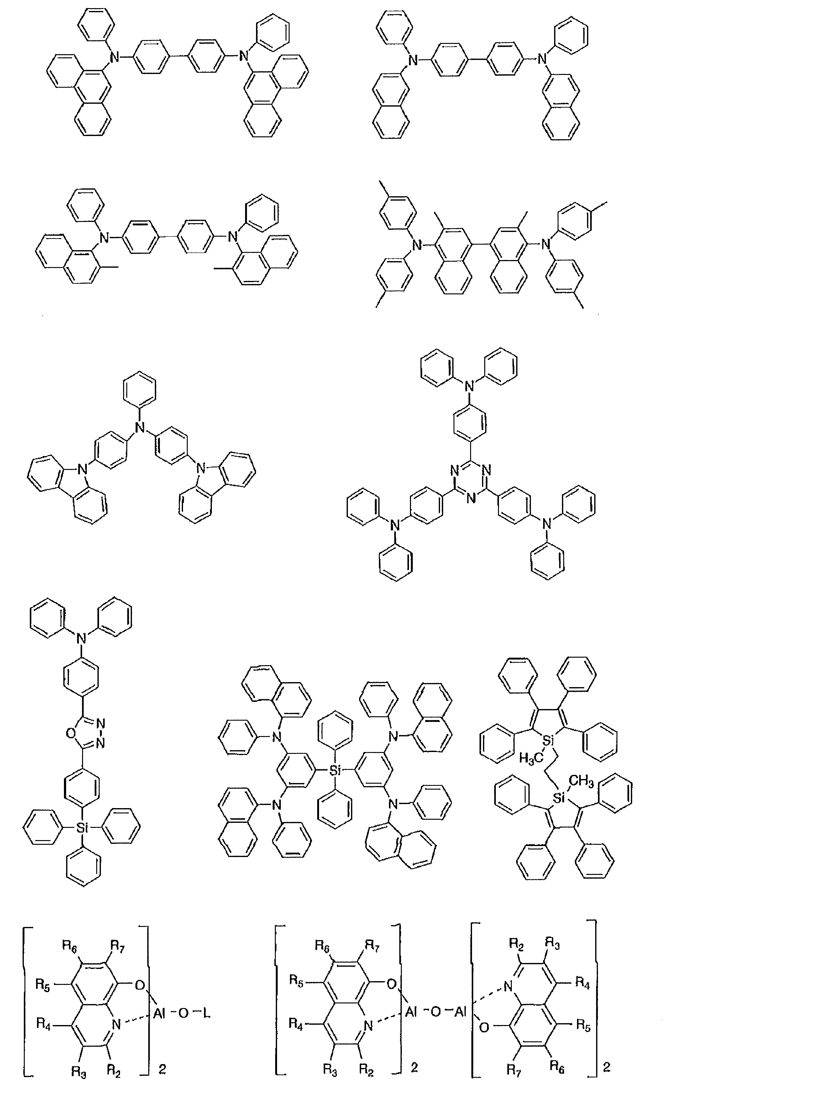


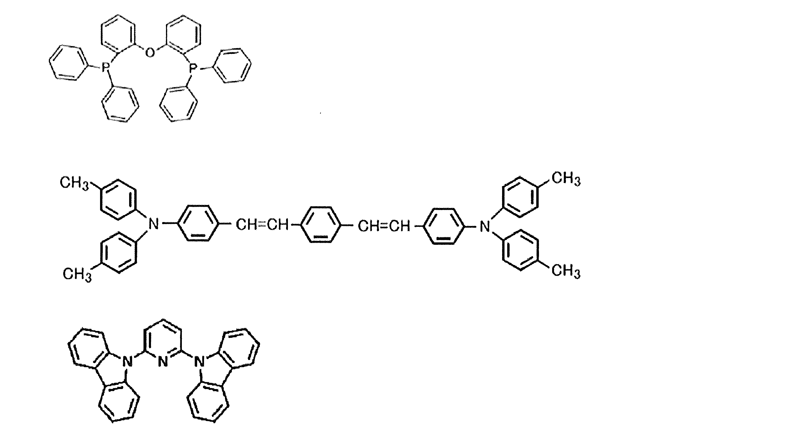
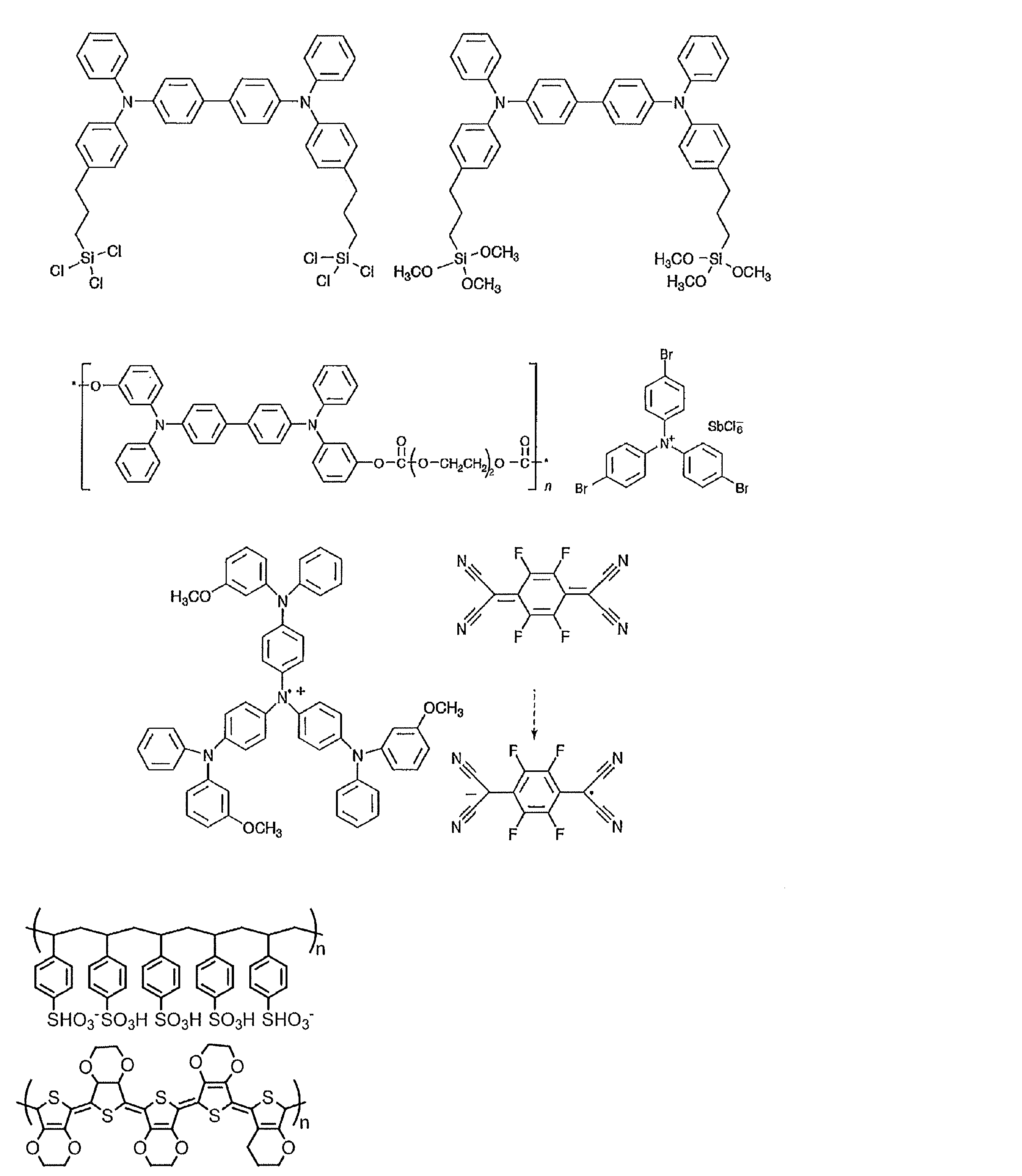


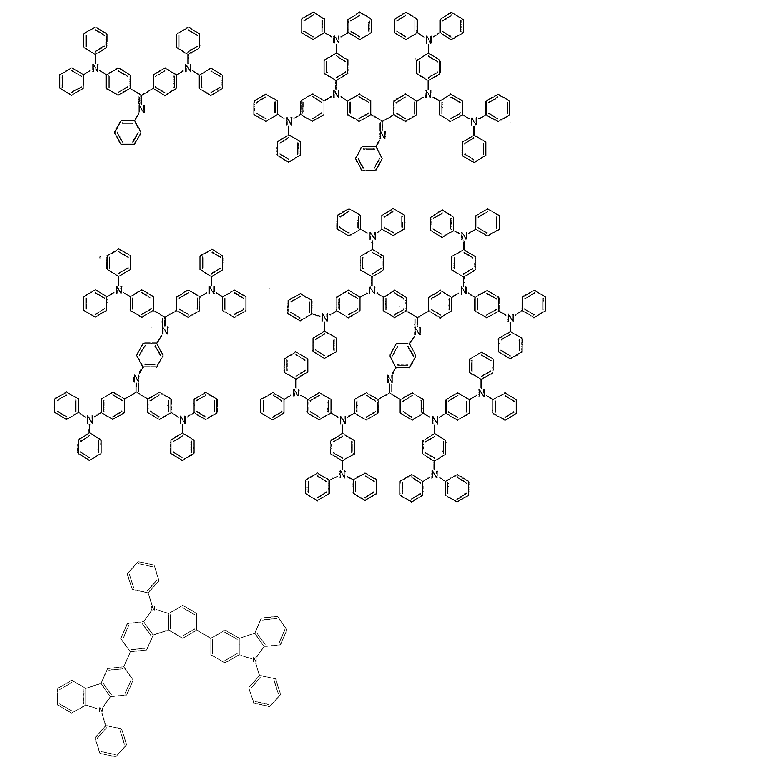
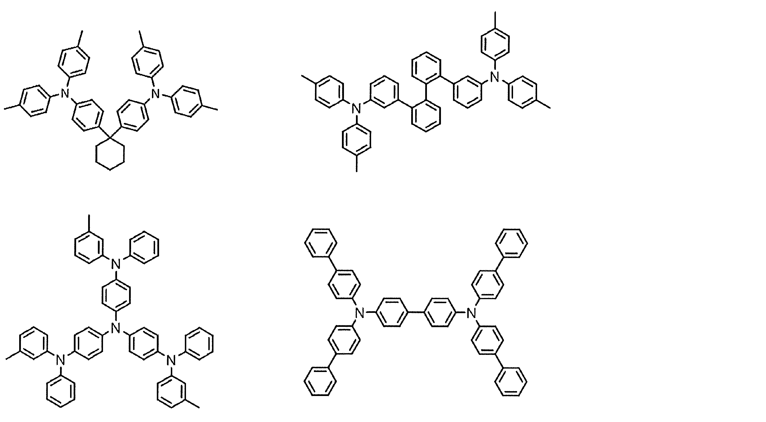
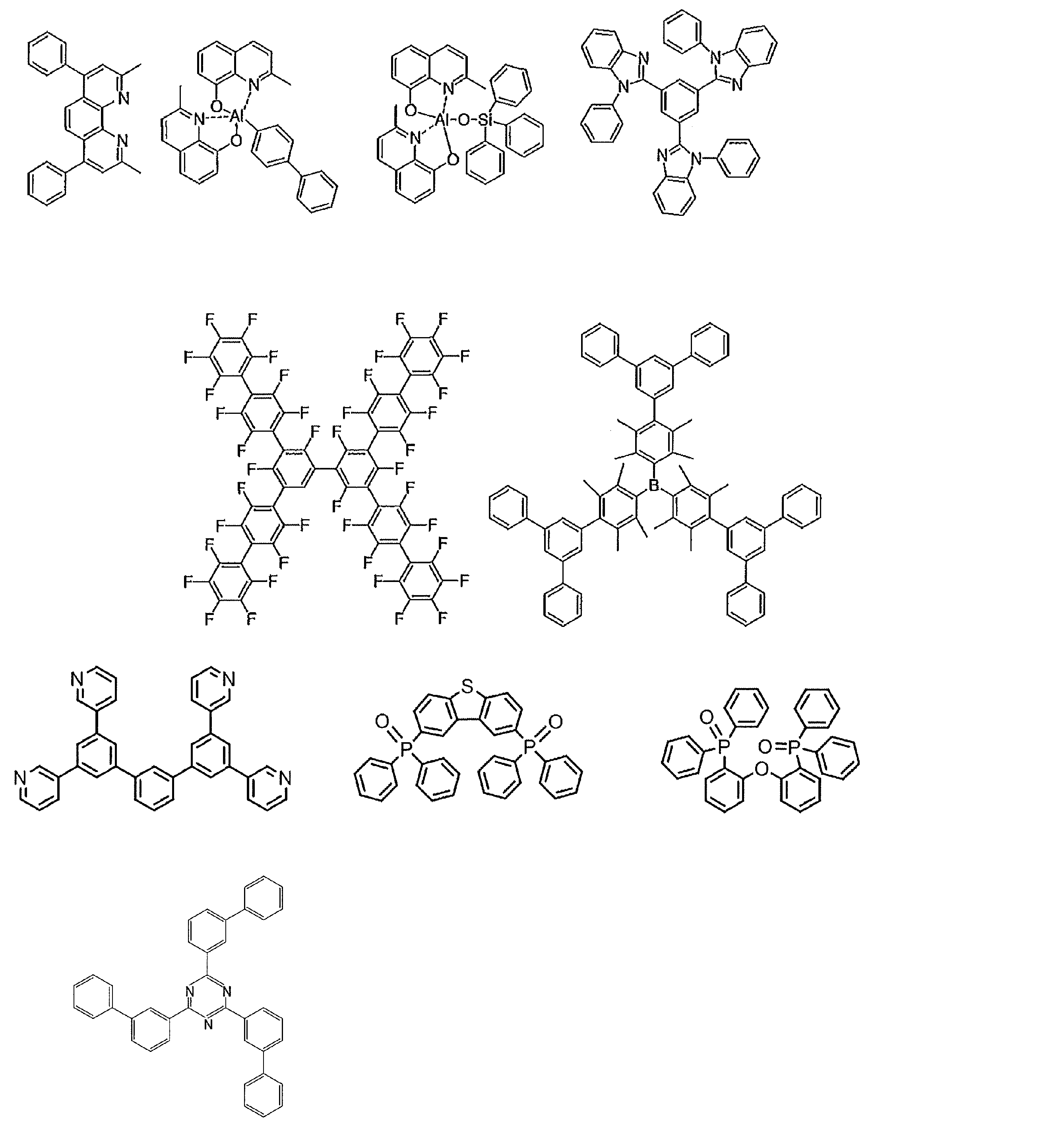
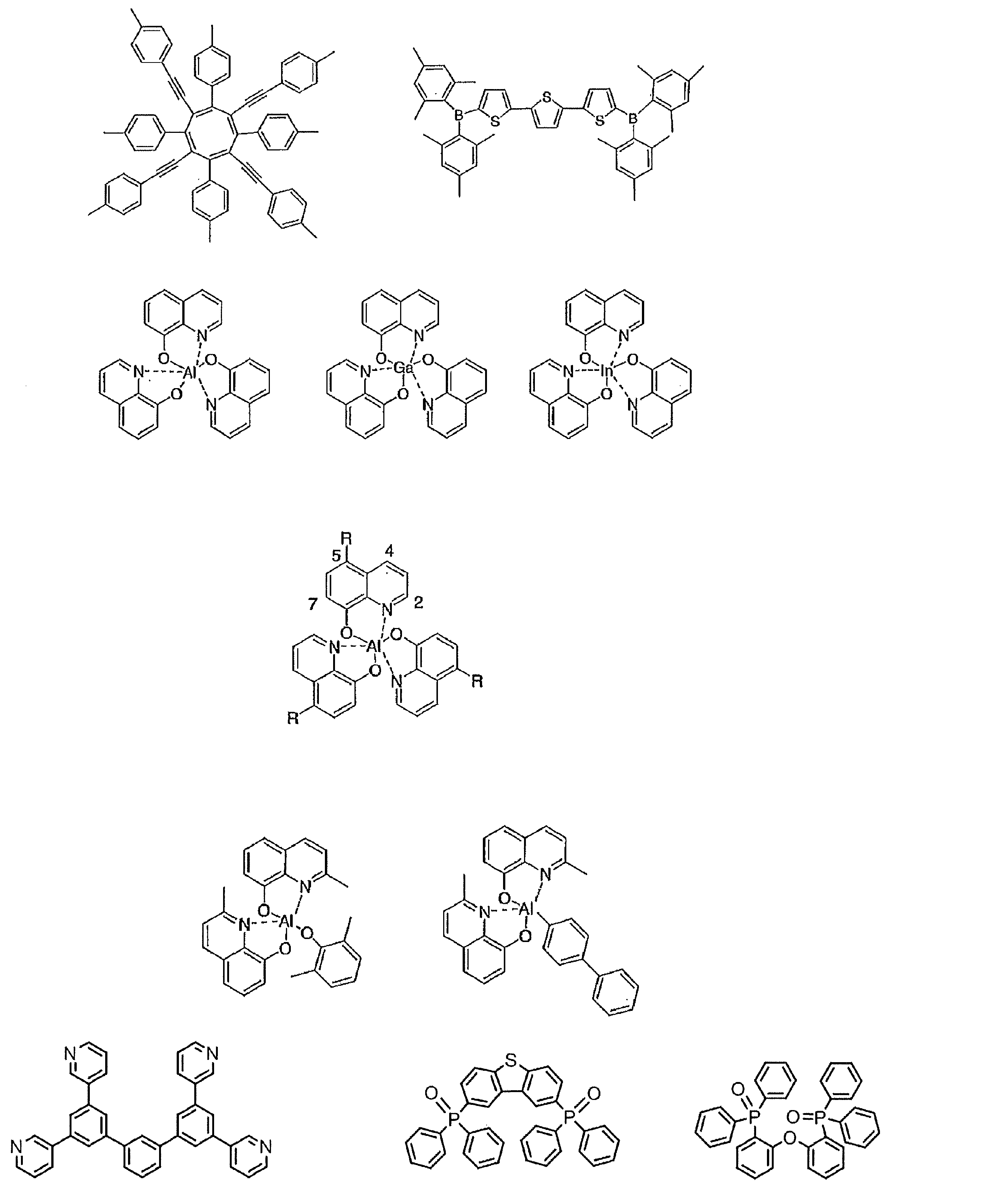
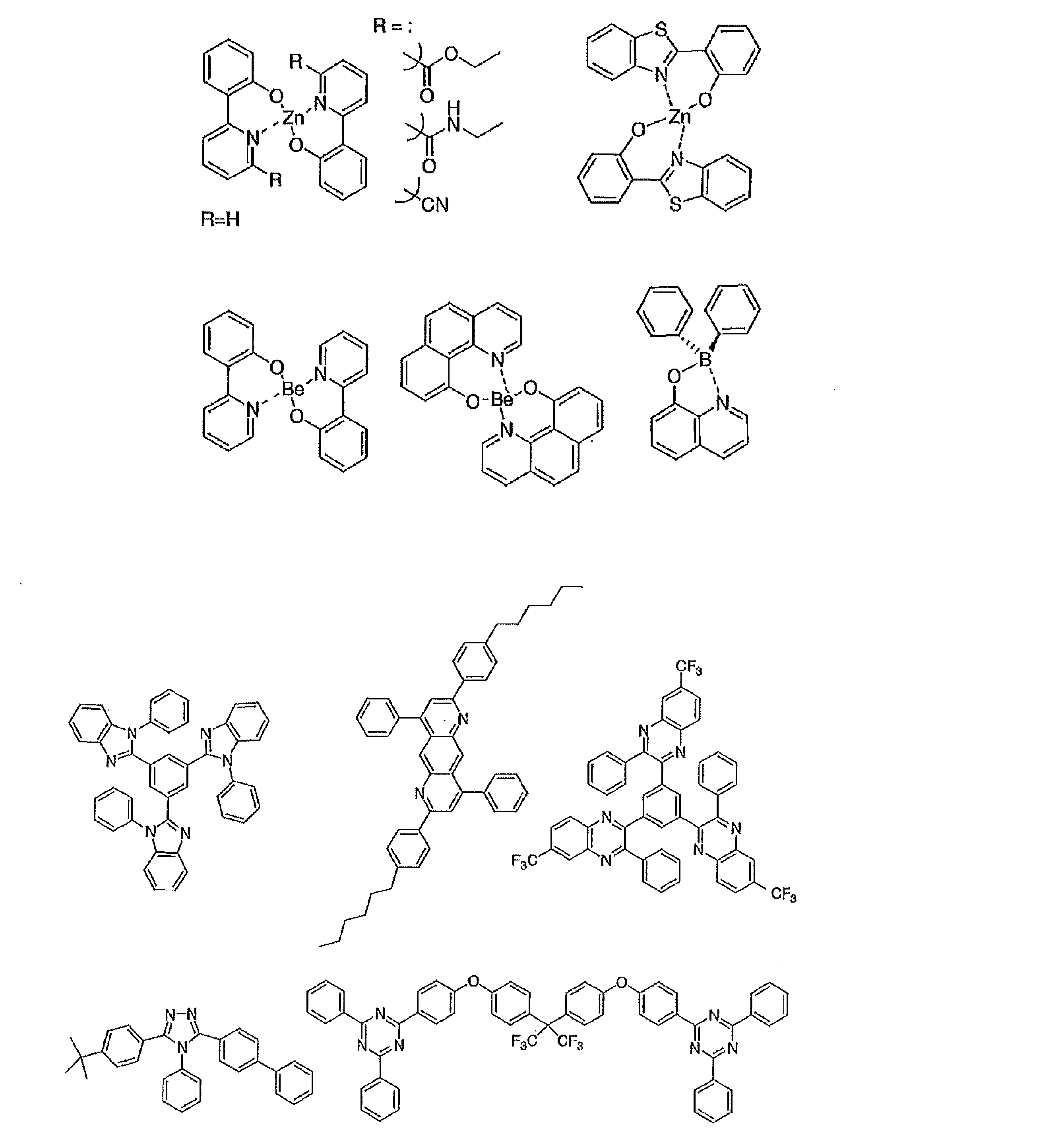

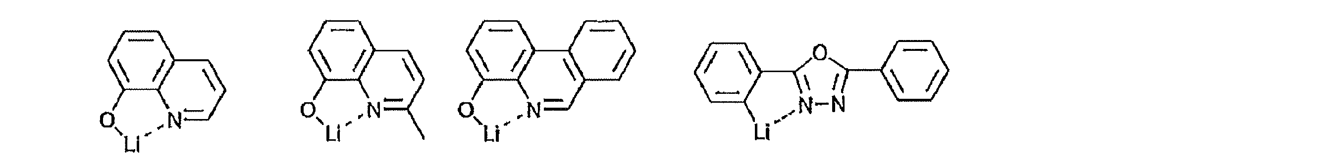

一方、りん光については、本発明の化合物のような通常の有機化合物では、励起三重項エネルギーは不安定で熱等に変換され、寿命が短く直ちに失活するため、室温では殆ど観測できない。通常の有機化合物の励起三重項エネルギーを測定するためには、極低温の条件での発光を観測することにより測定可能である。

中間体3(4.3g、8.5mmol)、ジフェニルアミン(3.2g、18.7mmol:ナカライテスク(株)製)、テトラフルオロホウ酸トリ-tert-ブチルホスフィン(0.40g、0.22mmol:シグマアルドリッチ製)、ナトリウム-tert-ブトキシド(2.8g、29.2mmol:東京化成工業(株)製)およびトリス(ジベンジリデンアセトン)(クロロホルム)パラジウム(0)(0.056g、0.054mmol)のトルエン(200mL:関東化学(株)製)溶液をアルゴン雰囲気下で1時間、80℃で加熱した。次に、室温で放冷後、反応液にトルエン(250mL)と水(200mL)を加えて分液した。有機層を無水硫酸マグネシウムで乾燥後、溶媒をエバポレーターで留去し、酢酸エチルとヘキサンの混合溶媒から再結晶を行い、中間体4を黒緑色固体として得た(4.24g、収率84%)。
中間体4(3.0g、5.1mmol)アニソール(16mL:シグマアルドリッチ製)溶液を、無水塩化アルミニウム(III)(5.0g、37.8mmol:和光純薬工業(株)製)アニソール(4.7mL:シグマアルドリッチ製)懸濁液に氷冷下で滴下した後、21時間、60℃で加熱した。次に、室温で放冷後、反応液にジクロロメタン(100mL)と水(50mL)を加えて分液し、有機層を5%炭酸水素ナトリウム水溶液(50mL)、飽和食塩水(50mL)で洗った。有機層を無水硫酸マグネシウムで乾燥後、溶媒をエバポレーターで留去した。残渣をシリカゲルカラムクロマトグラフィー(ジクロロメタン40%ヘキサン60%)で精製し、中間体5を黒緑色固体として得た(2.23g、収率76%)。


トリシクロヘキシルホスフィン(0.053g、0.19mmol:strem chemicals製)、トリス(ジベンジリデンアセトン)(クロロホルム)パラジウム(0)(0.043g、0.041mmol)1,4-ジオキサン(15mL:和光純薬工業(株)製)溶液を、室温で30分撹拌した。これに化合物9(1.64g、2.5mmol)、ビス(ピナコラート)ジボロン(0.70g、2.8mmol:和光純薬工業(株)製)、および酢酸カリウム(0.53g、11.0mmol和光純薬工業(株)製)を入れ、アルゴン雰囲気下で18時間、80℃に加熱した。次に、室温まで放冷後、反応液に水(5mL)、トルエン(20mL)を入れ分液した。有機層を飽和食塩水(10mL)で洗った後、無水硫酸マグネシウムで乾燥させた。溶媒をエバポレーターで留去し、中間体10を含む混合物を得た(1.6g)。
中間体10を含む混合物(1.6g)、2-クロロ-4,6-ジフェニル-1,3,5-トリアジン(0.0787g、2.9mmol)、リン酸カリウム(1.0g、4.7mmol)、トリス(ジベンジリデンアセトン)(クロロホルム)パラジウム(0)(0.014g、0.014mmol)および2-ジシクロヘキシルホスフィノ-2’,6’-ジメトキシビフェニル(0.027g、0.067mmol)をトルエン(5mL)水(0.5mL)混合溶媒中に溶解させ、100℃で2時間加熱した。室温まで放冷後、反応液をジクロロメタンで薄め、シリカゲルカラム中を通した。この溶液をエバポレーターで留去し、残渣をシリカゲルカラムクロマトグラフィー(ジクロロメタン20%、ヘキサン80%)で精製した後、ジクロロメタン、ヘキサン混合溶媒から2回再結晶を行い、化合物1を黄色結晶として得た(0.98g)。さらに、この結晶を昇華精製し、化合物1を黄色固体として得た(0.70g)。
mp265℃; 1H-NMR(300MHz Acetone D6):δ9.143(d, J=8.7Hz, 2H)、8.931(dd, J1=8.0Hz, J2=1.4Hz,4H)、8.003(d, J=8.7, 2H)、7.944(d, J=1.8Hz, 2H)、7.733-7.650(m, 6H)、7.628(s, 2H)、7.311(d, J=2.4Hz, 2H)、7.278-7.212(m,10H)、7.072-6.930(m,10H)

1H NMR (600 MHz, CDCl3): δ7.75-7.73 (m, 3H),7.45(d, J = 2.4 Hz, 1H), 7.31-7.27 (m, 3H),7.23-7.18 (m, 10H), 7.06 (d, J= 7.8 Hz, 8H),6.93 (t, J = 7.5 Hz, 4H), 2.50 (s, 3H)
1H NMR (600 MHz, CDCl3): δ8.78 (d, J = 6.6 Hz, 4H), 8.60 (d, J = 8.4 Hz, 1H), 7.79 (d, J = 6.6 Hz, 2H), 7.67-7.56 (m, 8H), 7.27-7.24 (m, 4H), 7.24-7.18 (m, 8H), 7.09 (d, J = 8.4 Hz, 8H), 6.95 (t, J = 7.5 Hz, 4H), 2.98 (s, 3H)

1H NMR (600 MHz, CDCl3): δ7.75 (s, 2H), 7.31-7.27(m, 4H), 7.23-7.16 (m, 10H), 7.06 (d, J = 7.8 Hz, 8H), 6.93 (t, J = 7.2 Hz, 4H), 2.52 (s, 6H)
1H NMR (600 MHz, CDCl3):δ8.75 (d, J = 7.8 Hz, 4H), 7.79 (d, J = 1.8 Hz, 2H), 7.64 (t, J = 7.2 Hz, 2H), 7.59 (t, J = 7.5 Hz, 4H), 7.48 (d, J = 8.4 Hz, 2H), 7.43 (s, 2H), 7.28-7.24 (m, 2H), 7.22 (t, J = 8.1 Hz, 8H), 7.09 (d, J = 8.4 Hz, 8H), 6.94 (t, J = 7.5 Hz, 4H), 2.44 (s, 6H)

1H NMR (600 MHz, CDCl3): δ7.77 (s, 2H), 7.66-7.61(m, 1H), 7.54-7.49 (m 1H), 7.28-7.14 (m, 13H),7.07 (d, J = 7.8 Hz, 8H), 6.93 (t, J = 7.5 Hz, 4H), 2.07 (s, 3H)
1H NMR (600 MHz, CDCl3):δ8.88 (s, 1H), 8.85-8.76 (m, 5H), 7.81 (s, 2H), 7.67-7.58 (m, 8H), 7.24-7.6.94 (m, 23H), 2.29 (s, 3H)
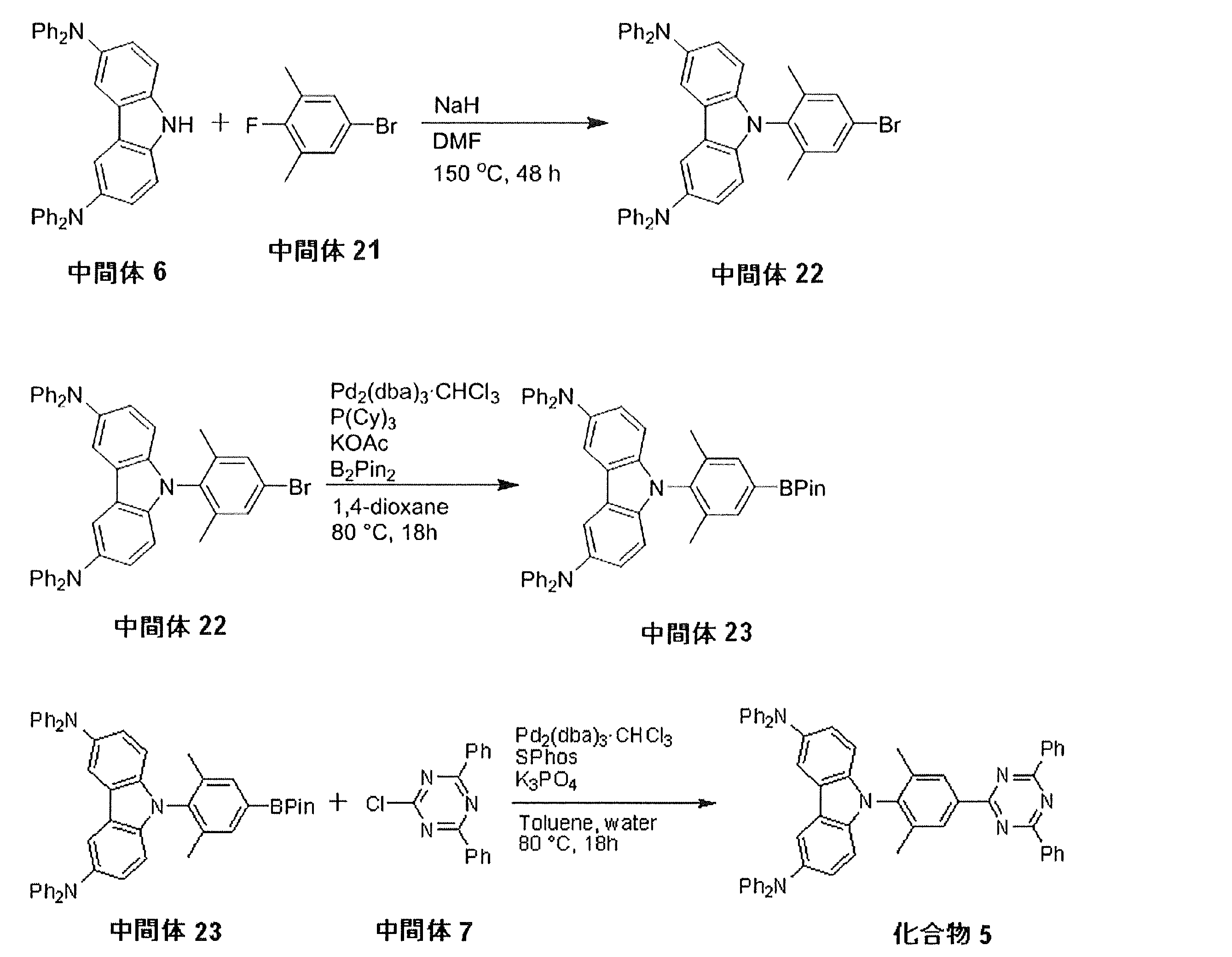
1H NMR (600 MHz, CDCl3): δ7.78 (s, 2H), 7.44(s, 2H), 7.24-7.22 (m 8H),7.07 (d, J = 7.8 Hz, 8H), 6.93 (t, J = 7.2 Hz, 4H), 6.82 (d, J = 9.0 Hz, 2H), 1.93 (s, 6H)
1H NMR (600 MHz, CDCl3): δ8.82 (d, J = 6.6 Hz, 4H), 8.66 (s, 2H), 7.82 (s, 2H), 7.67-7.58 (m, 8H), 7.22 (t, J = 8.1 Hz, 8H), 7.10 (d, J = 7.8 Hz, 8H), 6.97-6.85 (m, 6H), 2.14 (s, 6H)
Ar雰囲気のグローブボックス中で化合物1のトルエン溶液(濃度10-5mol/L)を調製し、370nm励起光による発光スペクトルを測定した。結果を図2に示す。また、Arでバブリングして発光波長550nmの過渡減衰曲線を300Kで測定した結果を図3に示す(τ1=14.3ns、τ2=3.3μs)。この過渡減衰曲線は、化合物に励起光を当てて発光強度が失活してゆく過程を測定した発光寿命測定結果を示すものである。通常の一成分の発光(蛍光もしくはリン光)では発光強度は単一指数関数的に減衰する。これは、グラフの縦軸がセミlog である場合には、直線的に減衰することを意味している。化合物1の過渡減衰曲線では、観測初期にこのような直線的成分(蛍光)が観測されているが、それ以降は直線性から外れる成分が現れている。これは遅延成分の発光であり、初期の成分と加算される信号は、長時間側に裾をひくゆるい曲線になる。このように発光寿命を測定することによって、化合物1は蛍光成分のほかに遅延成分を含む発光体であることが確認された。フォトルミネッセンス量子収率は、O2バブリングで26%、バブリングなしで48%、N2バブリングで65%であった。
また、化合物2のトルエン溶液(濃度10-5mol/L)を調製し、吸収発光スペクトルを測定した結果を図4に示す。また、ArバブリングなしとArバブリングありの条件下で測定したピーク発光波長の過渡減衰曲線を図5に示す。Arバブリングありの条件下での測定において遅延蛍光が認められた。フォトルミネッセンス量子収率は、Arバブリングなしで47%、Arバブリングありで84%であった。
また、化合物3のトルエン溶液(濃度10-5mol/L)を調製し、吸収発光スペクトルを測定した結果を図6に示す。また、ArバブリングなしとArバブリングありの条件下で測定したピーク発光波長の過渡減衰曲線を図7に示す。Arバブリングありの条件下での測定において遅延蛍光が認められた。フォトルミネッセンス量子収率は、Arバブリングなしで11%、Arバブリングありで42%であった。
また、化合物4のトルエン溶液(濃度10-5mol/L)を調製し、吸収発光スペクトルを測定した結果を図8に示す。また、ArバブリングなしとArバブリングありの条件下で測定したピーク発光波長の過渡減衰曲線を図9に示す。Arバブリングありの条件下での測定において遅延蛍光が認められた。フォトルミネッセンス量子収率は、Arバブリングなしで31%、Arバブリングありで60%であった。
また、化合物5のトルエン溶液(濃度10-5mol/L)を調製し、吸収発光スペクトルを測定した結果を図10に示す。また、ArバブリングなしとArバブリングありの条件下で測定したピーク発光波長の過渡減衰曲線を図11に示す。Arバブリングありの条件下での測定において遅延蛍光が認められた。フォトルミネッセンス量子収率は、Arバブリングなしで15%、Arバブリングありで53%であった。
化合物1のかわりに下記の化合物Aを用いて実施例1と同じ方法によりトルエン溶液を調製した。吸収発光スペクトルを図12に示す。また、実施例1と同じ条件にて得た過渡減衰曲線を図13に示す。遅延蛍光は認められなかった。

石英基板上に真空蒸着法にて、真空度10-4Pa以下の条件にて化合物1の薄膜を50nmの厚さで形成して有機フォトルミネッセンス素子とした。作製した有機フォトルミネッセンス素子について、330nm励起光による発光スペクトルを測定した結果を図2に示す。
石英基板上に真空蒸着法にて、真空度10-4Pa以下の条件にて化合物1とCBPとを異なる蒸着源から蒸着し、化合物1の濃度が6.0重量%である薄膜を100nmの厚さで形成して有機フォトルミネッセンス素子とした。作製した有機フォトルミネッセンス素子について、330nm励起光による発光スペクトルを測定した結果を図14に示す。
膜厚50nmのインジウム・スズ酸化物(ITO)からなる陽極が形成されたガラス基板上に、各薄膜を真空蒸着法にて、真空度10-4Pa以下で積層した。まず、ITO上にα-NPDを100nmの厚さに形成した。次に、化合物1とCBPを異なる蒸着源から共蒸着し、40nmの厚さの層を形成して発光層とした。この時、化合物1の濃度は6.0重量%とした。次に、BAlqを30nmの厚さに形成し、さらに8-ヒドロキシキノリノァートリチウム(Liq)を1nm真空蒸着し、次いでアルミニウム(Al)を80nmの厚さに蒸着することにより陰極を形成し、有機エレクトロルミネッセンス素子1とした。
α-NPDのかわりにTAPCを用いた点だけを変更して、同様の手順により有機エレクトロルミネッセンス素子2を作製した。
α-NPDのかわりにTAPCを用いるとともに、BAlqのかわりにBmPyPhBを用いた点だけを変更して、同様の手順により有機エレクトロルミネッセンス素子3を作製した。
作製した有機エレクトロルミネッセンス素子の発光スペクトルを図15に示す。素子1~3ともに発光スペクトルは重なり合った。図16に電流密度-電圧特性を示し、図17に電流密度-外部量子効率特性を示す。
また、α-NPDのかわりにTAPCを用いるとともに、化合物1の濃度を6.0重量%から9.0重量%とした点だけを変更して、素子1と同様の手順により有機エレクトロルミネッセンス素子4を作製した。この素子4は、外部量子効率29.6%を達成した。
素子1~4はいずれも高い外部量子効率を達成している。仮に発光量子効率が100%の蛍光材料を用いてバランスの取れた理想的な有機エレクトロルミネッセンス素子を試作したとすると、光取り出し効率が20~30%であれば、蛍光発光の外部量子効率は5~7.5%となる。この値が一般に、蛍光材料を用いた有機エレクトロルミネッセンス素子の外部量子効率の理論限界値とされている。本発明の有機エレクトロルミネッセンス素子1~4は、理論限界値を超える高い外部量子効率を実現している点で極めて優れている。
実施例3における素子1の作製において用いた化合物1のかわりにIr(ppy)3を用いた点だけを変更して比較用の有機エレクトロルミネッセンス素子(比較素子)を作製した。作製した比較素子の電流密度-電圧特性を図16に示し、電流密度-外部量子効率特性を図17に示す。図から明らかなように、比較素子よりも素子1~4の外部量子効率の方がかなり大きいことが確認された。また、電流効率に関しても、比較素子よりも素子1~4の外部量子効率の方がかなり高いことが確認された。
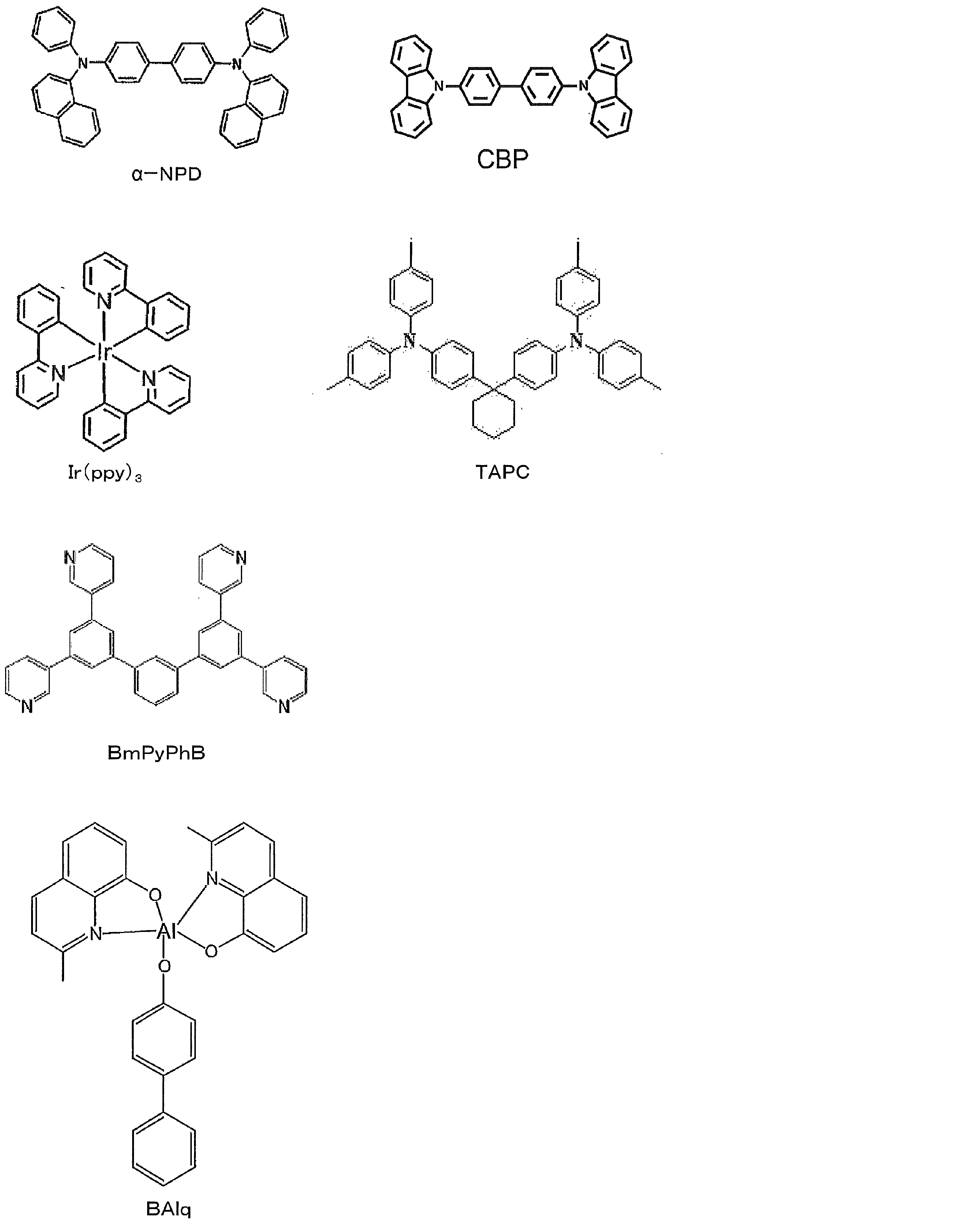
2 陽極
3 正孔注入層
4 正孔輸送層
5 発光層
6 電子輸送層
7 陰極
Claims (14)
- 下記一般式(1)で表される化合物。

- 一般式(1)のR1~R4の少なくとも1つが置換もしくは無置換のジアリールアミノ基であって、R5~R8の少なくとも1つが置換もしくは無置換のジアリールアミノ基であることを特徴とする請求項1に記載の化合物。
- 一般式(1)のR3およびR6が置換もしくは無置換のジアリールアミノ基であることを特徴とする請求項2に記載の化合物。
- 一般式(1)のR1~R8の少なくとも1つが置換もしくは無置換のジフェニルアミノ基であることを特徴とする請求項1~3のいずれか1項に記載の化合物。
- 一般式(1)のAr2およびAr3が各々独立に置換もしくは無置換のフェニル基であることを特徴とする請求項1~4のいずれか1項に記載の化合物。
- 一般式(1)のAr1が各々独立に置換もしくは無置換のフェニレン基、置換もしくは無置換のナフチレン基、または置換もしくは無置換のアントラセニレン基であることを特徴とする請求項1~5のいずれか1項に記載の化合物。
- 下記一般式(2)で表される構造を有することを特徴とする請求項1に記載の化合物。
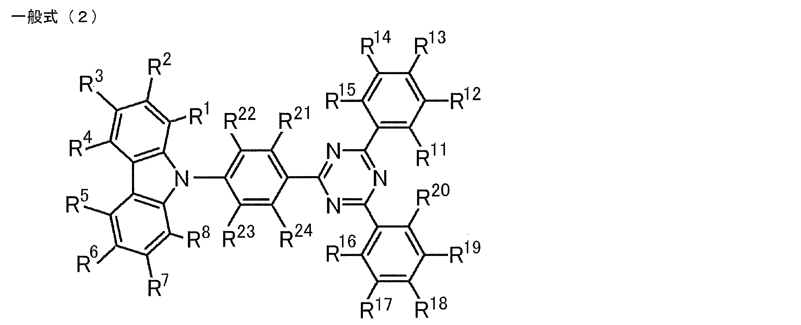
- 一般式(2)のR1~R4の少なくとも1つが置換もしくは無置換のジアリールアミノ基であって、R5~R8の少なくとも1つが置換もしくは無置換のジアリールアミノ基であることを特徴とする請求項7に記載の化合物。
- 一般式(2)のR3およびR6が置換もしくは無置換のジアリールアミノ基であることを特徴とする請求項8に記載の化合物。
- 請求項1~9のいずれか1項に記載の化合物からなる発光材料。
- 下記一般式(1)で表される構造を有する遅延蛍光体。

- 請求項10に記載の発光材料を含む発光層を基板上に有することを特徴とする有機発光素子。
- 遅延蛍光を放射することを特徴とする請求項12に記載の有機発光素子。
- 有機エレクトロルミネッセンス素子であることを特徴とする請求項12または13に記載の有機発光素子。
Priority Applications (5)
| Application Number | Priority Date | Filing Date | Title |
|---|---|---|---|
| EP14757587.2A EP2963035B1 (en) | 2013-03-01 | 2014-02-28 | Compound, light-emitting material, and organic light-emitting element |
| US14/771,520 US9818955B2 (en) | 2013-03-01 | 2014-02-28 | Compound, light emitting material, and organic light emitting device |
| JP2015503044A JP6263524B2 (ja) | 2013-03-01 | 2014-02-28 | 化合物、発光材料および有機発光素子 |
| CN201480010316.7A CN105073737B (zh) | 2013-03-01 | 2014-02-28 | 化合物、发光材料及有机发光元件 |
| KR1020157026946A KR101999881B1 (ko) | 2013-03-01 | 2014-02-28 | 화합물, 발광 재료 및 유기 발광 소자 |
Applications Claiming Priority (2)
| Application Number | Priority Date | Filing Date | Title |
|---|---|---|---|
| JP2013041106 | 2013-03-01 | ||
| JP2013-041106 | 2013-03-01 |
Publications (1)
| Publication Number | Publication Date |
|---|---|
| WO2014133121A1 true WO2014133121A1 (ja) | 2014-09-04 |
Family
ID=51428379
Family Applications (1)
| Application Number | Title | Priority Date | Filing Date |
|---|---|---|---|
| PCT/JP2014/055005 WO2014133121A1 (ja) | 2013-03-01 | 2014-02-28 | 化合物、発光材料および有機発光素子 |
Country Status (7)
| Country | Link |
|---|---|
| US (1) | US9818955B2 (ja) |
| EP (1) | EP2963035B1 (ja) |
| JP (1) | JP6263524B2 (ja) |
| KR (1) | KR101999881B1 (ja) |
| CN (1) | CN105073737B (ja) |
| TW (1) | TWI615389B (ja) |
| WO (1) | WO2014133121A1 (ja) |
Cited By (21)
| Publication number | Priority date | Publication date | Assignee | Title |
|---|---|---|---|---|
| KR20160045569A (ko) * | 2014-10-17 | 2016-04-27 | 엘지디스플레이 주식회사 | 지연 형광 화합물, 이를 포함하는 유기발광다이오드소자 및 표시장치 |
| EP3065190A1 (en) * | 2015-03-02 | 2016-09-07 | Ecole Polytechnique Fédérale de Lausanne (EPFL) | Small molecule hole transporting material for optoelectronic and photoelectrochemical devices |
| JP2017054972A (ja) * | 2015-09-10 | 2017-03-16 | コニカミノルタ株式会社 | 有機エレクトロルミネッセンス素子、表示装置、照明装置、π共役系化合物、及び発光性薄膜 |
| CN106661001A (zh) * | 2014-05-14 | 2017-05-10 | 哈佛学院院长等 | 有机发光二极管材料 |
| JP2018100411A (ja) * | 2016-12-21 | 2018-06-28 | 国立大学法人九州大学 | 発光材料、化合物および有機発光素子 |
| WO2018207750A1 (ja) * | 2017-05-08 | 2018-11-15 | 国立大学法人京都大学 | 化合物、発光材料および有機発光素子 |
| WO2020076796A1 (en) | 2018-10-09 | 2020-04-16 | Kyulux, Inc. | Novel composition of matter for use in organic light-emitting diodes |
| WO2021157642A1 (ja) | 2020-02-04 | 2021-08-12 | 株式会社Kyulux | ホスト材料、組成物および有機発光素子 |
| US11101440B2 (en) | 2015-07-01 | 2021-08-24 | Kyushu University, National University Corporation | Organic electroluminescent device |
| WO2021235549A1 (ja) | 2020-05-22 | 2021-11-25 | 株式会社Kyulux | 化合物、発光材料および発光素子 |
| WO2022025248A1 (ja) | 2020-07-31 | 2022-02-03 | 株式会社Kyulux | 化合物、発光材料および発光素子 |
| US11335872B2 (en) | 2016-09-06 | 2022-05-17 | Kyulux, Inc. | Organic light-emitting device |
| WO2022168956A1 (ja) | 2021-02-04 | 2022-08-11 | 株式会社Kyulux | 化合物、発光材料および有機発光素子 |
| US11476435B2 (en) | 2017-08-24 | 2022-10-18 | Kyushu University, National University Corporation | Film and organic light-emitting device containing perovskite-type compound and organic light-emitting material |
| US11482679B2 (en) | 2017-05-23 | 2022-10-25 | Kyushu University, National University Corporation | Compound, light-emitting lifetime lengthening agent, use of n-type compound, film and light-emitting device |
| WO2022244503A1 (ja) | 2021-05-20 | 2022-11-24 | 株式会社Kyulux | 有機発光素子 |
| WO2022270602A1 (ja) | 2021-06-23 | 2022-12-29 | 株式会社Kyulux | 有機発光素子および膜 |
| WO2022270354A1 (ja) | 2021-06-23 | 2022-12-29 | 株式会社Kyulux | 化合物、発光材料および有機発光素子 |
| WO2023282224A1 (ja) | 2021-07-06 | 2023-01-12 | 株式会社Kyulux | 有機発光素子およびその設計方法 |
| WO2023053835A1 (ja) | 2021-09-28 | 2023-04-06 | 株式会社Kyulux | 化合物、組成物、ホスト材料、電子障壁材料および有機発光素子 |
| US11930654B2 (en) | 2017-07-06 | 2024-03-12 | Kyulux, Inc. | Organic light-emitting element |
Families Citing this family (11)
| Publication number | Priority date | Publication date | Assignee | Title |
|---|---|---|---|---|
| JP6526625B2 (ja) | 2014-03-07 | 2019-06-05 | 株式会社Kyulux | 発光材料、有機発光素子および化合物 |
| CN107880027B (zh) * | 2016-09-30 | 2021-03-02 | 中节能万润股份有限公司 | 一种以三嗪为核心的化合物及其在有机电致发光器件上的应用 |
| US10833276B2 (en) | 2016-11-21 | 2020-11-10 | Universal Display Corporation | Organic electroluminescent materials and devices |
| CN108148048B (zh) * | 2016-12-06 | 2021-03-30 | 中节能万润股份有限公司 | 以氮杂苯为核心的化合物及其在有机电致发光器件上的应用 |
| KR20180066339A (ko) | 2016-12-07 | 2018-06-19 | 삼성디스플레이 주식회사 | 축합환 화합물 및 이를 포함한 유기 발광 소자 |
| US10418567B2 (en) * | 2016-12-22 | 2019-09-17 | Feng-wen Yen | Organic compound for organic EL device and using the same |
| CN108336235B (zh) * | 2017-01-20 | 2020-07-10 | 中节能万润股份有限公司 | 一种双主体材料的有机电致发光器件 |
| KR20190035503A (ko) * | 2017-09-25 | 2019-04-03 | 롬엔드하스전자재료코리아유한회사 | 유기 전계 발광 화합물 및 이를 포함하는 유기 전계 발광 소자 |
| CN108424420B (zh) * | 2017-09-30 | 2021-01-12 | 北京绿人科技有限责任公司 | 含有硅原子的三嗪化合物及其应用和一种有机电致发光器件 |
| KR20190119701A (ko) | 2018-04-12 | 2019-10-23 | 삼성디스플레이 주식회사 | 헤테로시클릭 화합물 및 이를 포함한 유기 발광 소자 |
| KR20210056497A (ko) | 2019-11-08 | 2021-05-20 | 삼성디스플레이 주식회사 | 유기 전계 발광 소자 및 유기 전계 발광 소자용 다환 화합물 |
Citations (5)
| Publication number | Priority date | Publication date | Assignee | Title |
|---|---|---|---|---|
| JP2002193952A (ja) | 2000-12-25 | 2002-07-10 | Fuji Photo Film Co Ltd | 新規含窒素へテロ環化合物、発光素子材料およびそれらを使用した発光素子 |
| WO2005076669A1 (ja) | 2004-02-09 | 2005-08-18 | Idemitsu Kosan Co., Ltd. | 有機エレクトロルミネッセンス素子 |
| JP2009021336A (ja) | 2007-07-11 | 2009-01-29 | Konica Minolta Holdings Inc | 有機エレクトロルミネッセンス素子、表示装置及び照明装置 |
| WO2010021524A2 (ko) * | 2008-08-22 | 2010-02-25 | 주식회사 엘지화학 | 유기 전자 소자 재료 및 이를 이용한 유기 전자 소자 |
| WO2012015274A2 (ko) | 2010-07-30 | 2012-02-02 | 롬엔드하스전재재로코리아유한회사 | 유기발광화합물을 발광재료로서 채용하고 있는 유기 전계 발광 소자 |
Family Cites Families (11)
| Publication number | Priority date | Publication date | Assignee | Title |
|---|---|---|---|---|
| KR101801048B1 (ko) | 2009-06-08 | 2017-11-28 | 에스에프씨 주식회사 | 인돌로카바졸 유도체 및 이를 이용한 유기전계발광소자 |
| KR101801412B1 (ko) * | 2009-10-20 | 2017-11-24 | 토소가부시키가이샤 | 카바졸 화합물 및 그 용도 |
| KR101233380B1 (ko) * | 2009-10-21 | 2013-02-15 | 제일모직주식회사 | 신규한 유기광전소자용 화합물 및 이를 포함하는 유기광전소자 |
| KR20120009761A (ko) * | 2010-07-21 | 2012-02-02 | 롬엔드하스전자재료코리아유한회사 | 신규한 유기 발광 화합물 및 이를 포함하는 유기 전계 발광 소자 |
| KR101432599B1 (ko) * | 2010-08-04 | 2014-08-21 | 제일모직주식회사 | 유기광전소자용 화합물 및 이를 포함하는 유기광전소자 |
| WO2012077902A2 (ko) * | 2010-12-08 | 2012-06-14 | 제일모직 주식회사 | 유기광전자소자용 화합물, 이를 포함하는 유기발광소자 및 상기 유기발광소자를 포함하는 표시장치 |
| KR101788793B1 (ko) * | 2010-12-24 | 2017-10-20 | 에스에프씨 주식회사 | 피리딘 유도체 화합물 및 이를 포함하는 유기전계발광소자 |
| KR101463298B1 (ko) * | 2011-04-01 | 2014-11-20 | 주식회사 엘지화학 | 새로운 유기 발광 소자 재료 및 이를 이용한 유기 발광 소자 |
| JP6208424B2 (ja) * | 2012-12-05 | 2017-10-04 | 三星ディスプレイ株式會社Samsung Display Co.,Ltd. | フッ素置換されたアリール基を有するアミン誘導体、それを含む有機el材料及びそれを用いた有機el素子 |
| US9209411B2 (en) * | 2012-12-07 | 2015-12-08 | Universal Display Corporation | Organic electroluminescent materials and devices |
| WO2015125986A1 (ko) | 2014-02-20 | 2015-08-27 | 주식회사 두산 | 유기 화합물 및 이를 포함하는 유기 전계 발광 소자 |
-
2014
- 2014-02-27 TW TW103106934A patent/TWI615389B/zh active
- 2014-02-28 EP EP14757587.2A patent/EP2963035B1/en active Active
- 2014-02-28 US US14/771,520 patent/US9818955B2/en active Active
- 2014-02-28 CN CN201480010316.7A patent/CN105073737B/zh active Active
- 2014-02-28 JP JP2015503044A patent/JP6263524B2/ja active Active
- 2014-02-28 WO PCT/JP2014/055005 patent/WO2014133121A1/ja active Application Filing
- 2014-02-28 KR KR1020157026946A patent/KR101999881B1/ko active IP Right Grant
Patent Citations (5)
| Publication number | Priority date | Publication date | Assignee | Title |
|---|---|---|---|---|
| JP2002193952A (ja) | 2000-12-25 | 2002-07-10 | Fuji Photo Film Co Ltd | 新規含窒素へテロ環化合物、発光素子材料およびそれらを使用した発光素子 |
| WO2005076669A1 (ja) | 2004-02-09 | 2005-08-18 | Idemitsu Kosan Co., Ltd. | 有機エレクトロルミネッセンス素子 |
| JP2009021336A (ja) | 2007-07-11 | 2009-01-29 | Konica Minolta Holdings Inc | 有機エレクトロルミネッセンス素子、表示装置及び照明装置 |
| WO2010021524A2 (ko) * | 2008-08-22 | 2010-02-25 | 주식회사 엘지화학 | 유기 전자 소자 재료 및 이를 이용한 유기 전자 소자 |
| WO2012015274A2 (ko) | 2010-07-30 | 2012-02-02 | 롬엔드하스전재재로코리아유한회사 | 유기발광화합물을 발광재료로서 채용하고 있는 유기 전계 발광 소자 |
Non-Patent Citations (2)
| Title |
|---|
| KUNDU P ET AL.: "HIGH-TG CARBAZOLE DERIVATIVES AS BLUE-EMITTING HOLE-TRANSPORTING MATERIALS FOR ELECTROLUMINESCENT DEVICES", ADVANCED FUNCTIONAL MATERIALS, vol. 13, no. 6, 2003, pages 445 - 452, XP055280586 * |
| See also references of EP2963035A4 |
Cited By (30)
| Publication number | Priority date | Publication date | Assignee | Title |
|---|---|---|---|---|
| CN106661001A (zh) * | 2014-05-14 | 2017-05-10 | 哈佛学院院长等 | 有机发光二极管材料 |
| JP2017518281A (ja) * | 2014-05-14 | 2017-07-06 | プレジデント アンド フェローズ オブ ハーバード カレッジ | 有機発光ダイオード材料 |
| KR20160045569A (ko) * | 2014-10-17 | 2016-04-27 | 엘지디스플레이 주식회사 | 지연 형광 화합물, 이를 포함하는 유기발광다이오드소자 및 표시장치 |
| KR102503744B1 (ko) | 2014-10-17 | 2023-02-24 | 엘지디스플레이 주식회사 | 지연 형광 화합물, 이를 포함하는 유기발광다이오드소자 및 표시장치 |
| WO2016139570A1 (en) * | 2015-03-02 | 2016-09-09 | Ecole Polytechnique Federale De Lausanne (Epfl) | Small molecule hole transporting material for optoelectronic and photoelectrochemical devices |
| EP3065190A1 (en) * | 2015-03-02 | 2016-09-07 | Ecole Polytechnique Fédérale de Lausanne (EPFL) | Small molecule hole transporting material for optoelectronic and photoelectrochemical devices |
| CN107438597A (zh) * | 2015-03-02 | 2017-12-05 | 洛桑联邦理工学院 | 用于光电子装置和光电化学装置的小分子空穴传输材料 |
| CN107438597B (zh) * | 2015-03-02 | 2022-08-26 | 洛桑联邦理工学院 | 用于光电子装置和光电化学装置的小分子空穴传输材料 |
| US10680180B2 (en) | 2015-03-02 | 2020-06-09 | Ecole Polytechnique Federale De Lausanne (Epfl) | Small molecule hole transporting material for optoelectronic and photoelectrochemical devices |
| US11101440B2 (en) | 2015-07-01 | 2021-08-24 | Kyushu University, National University Corporation | Organic electroluminescent device |
| JP2017054972A (ja) * | 2015-09-10 | 2017-03-16 | コニカミノルタ株式会社 | 有機エレクトロルミネッセンス素子、表示装置、照明装置、π共役系化合物、及び発光性薄膜 |
| US11335872B2 (en) | 2016-09-06 | 2022-05-17 | Kyulux, Inc. | Organic light-emitting device |
| US11637244B2 (en) | 2016-12-21 | 2023-04-25 | Kyushu University, National University Corporation | Light-emitting material, compound, and organic light-emitting element |
| JP2018100411A (ja) * | 2016-12-21 | 2018-06-28 | 国立大学法人九州大学 | 発光材料、化合物および有機発光素子 |
| JP7076699B2 (ja) | 2016-12-21 | 2022-05-30 | 国立大学法人九州大学 | 発光材料、化合物および有機発光素子 |
| WO2018207750A1 (ja) * | 2017-05-08 | 2018-11-15 | 国立大学法人京都大学 | 化合物、発光材料および有機発光素子 |
| US11482679B2 (en) | 2017-05-23 | 2022-10-25 | Kyushu University, National University Corporation | Compound, light-emitting lifetime lengthening agent, use of n-type compound, film and light-emitting device |
| US11930654B2 (en) | 2017-07-06 | 2024-03-12 | Kyulux, Inc. | Organic light-emitting element |
| US11476435B2 (en) | 2017-08-24 | 2022-10-18 | Kyushu University, National University Corporation | Film and organic light-emitting device containing perovskite-type compound and organic light-emitting material |
| WO2020076796A1 (en) | 2018-10-09 | 2020-04-16 | Kyulux, Inc. | Novel composition of matter for use in organic light-emitting diodes |
| WO2021157642A1 (ja) | 2020-02-04 | 2021-08-12 | 株式会社Kyulux | ホスト材料、組成物および有機発光素子 |
| WO2021157593A1 (ja) | 2020-02-04 | 2021-08-12 | 株式会社Kyulux | 組成物、膜、有機発光素子、発光組成物を提供する方法およびプログラム |
| WO2021235549A1 (ja) | 2020-05-22 | 2021-11-25 | 株式会社Kyulux | 化合物、発光材料および発光素子 |
| WO2022025248A1 (ja) | 2020-07-31 | 2022-02-03 | 株式会社Kyulux | 化合物、発光材料および発光素子 |
| WO2022168956A1 (ja) | 2021-02-04 | 2022-08-11 | 株式会社Kyulux | 化合物、発光材料および有機発光素子 |
| WO2022244503A1 (ja) | 2021-05-20 | 2022-11-24 | 株式会社Kyulux | 有機発光素子 |
| WO2022270602A1 (ja) | 2021-06-23 | 2022-12-29 | 株式会社Kyulux | 有機発光素子および膜 |
| WO2022270354A1 (ja) | 2021-06-23 | 2022-12-29 | 株式会社Kyulux | 化合物、発光材料および有機発光素子 |
| WO2023282224A1 (ja) | 2021-07-06 | 2023-01-12 | 株式会社Kyulux | 有機発光素子およびその設計方法 |
| WO2023053835A1 (ja) | 2021-09-28 | 2023-04-06 | 株式会社Kyulux | 化合物、組成物、ホスト材料、電子障壁材料および有機発光素子 |
Also Published As
| Publication number | Publication date |
|---|---|
| US20160020402A1 (en) | 2016-01-21 |
| JP6263524B2 (ja) | 2018-01-17 |
| KR20150123907A (ko) | 2015-11-04 |
| JPWO2014133121A1 (ja) | 2017-02-02 |
| US9818955B2 (en) | 2017-11-14 |
| CN105073737A (zh) | 2015-11-18 |
| TW201443041A (zh) | 2014-11-16 |
| CN105073737B (zh) | 2019-05-14 |
| KR101999881B1 (ko) | 2019-07-12 |
| TWI615389B (zh) | 2018-02-21 |
| EP2963035A1 (en) | 2016-01-06 |
| EP2963035B1 (en) | 2021-09-01 |
| EP2963035A4 (en) | 2016-09-28 |
Similar Documents
| Publication | Publication Date | Title |
|---|---|---|
| JP6263524B2 (ja) | 化合物、発光材料および有機発光素子 | |
| JP6326050B2 (ja) | 化合物、発光材料および有機発光素子 | |
| JP6277182B2 (ja) | 化合物、発光材料および有機発光素子 | |
| JP6430370B2 (ja) | 発光材料、有機発光素子および化合物 | |
| JP6225111B2 (ja) | 発光材料、化合物、およびそれらを用いた有機発光素子 | |
| JP6284370B2 (ja) | 発光材料、有機発光素子および化合物 | |
| JP5594750B2 (ja) | 化合物、発光材料および有機発光素子 | |
| JP6293417B2 (ja) | 化合物、発光材料および有機発光素子 | |
| JP6367189B2 (ja) | 発光材料、有機発光素子および化合物 | |
| JP6383538B2 (ja) | 発光材料、有機発光素子および化合物 | |
| WO2015133501A1 (ja) | 発光材料、有機発光素子および化合物 | |
| WO2015080183A1 (ja) | 発光材料、有機発光素子および化合物 | |
| WO2014203840A1 (ja) | 赤色発光材料、有機発光素子および化合物 | |
| WO2015016200A1 (ja) | 化合物、発光材料および有機発光素子 | |
| WO2014126200A1 (ja) | 化合物、発光材料および有機発光素子 | |
| WO2013161437A1 (ja) | 発光材料および有機発光素子 | |
| WO2015137244A1 (ja) | 発光材料、有機発光素子および化合物 | |
| JP6647514B2 (ja) | 有機発光素子ならびにそれに用いる発光材料および化合物 | |
| WO2014126076A1 (ja) | 化合物、発光材料および有機発光素子 | |
| WO2017115834A1 (ja) | 化合物、発光材料および有機発光素子 | |
| JP6622484B2 (ja) | 発光材料、有機発光素子および化合物 | |
| JP2018111751A (ja) | 発光材料、化合物および有機発光素子 | |
| JP2016084283A (ja) | 化合物、発光材料および有機発光素子 |
Legal Events
| Date | Code | Title | Description |
|---|---|---|---|
| WWE | Wipo information: entry into national phase |
Ref document number: 201480010316.7 Country of ref document: CN |
|
| 121 | Ep: the epo has been informed by wipo that ep was designated in this application |
Ref document number: 14757587 Country of ref document: EP Kind code of ref document: A1 |
|
| ENP | Entry into the national phase |
Ref document number: 2015503044 Country of ref document: JP Kind code of ref document: A |
|
| WWE | Wipo information: entry into national phase |
Ref document number: 14771520 Country of ref document: US |
|
| NENP | Non-entry into the national phase |
Ref country code: DE |
|
| WWE | Wipo information: entry into national phase |
Ref document number: 2014757587 Country of ref document: EP |
|
| ENP | Entry into the national phase |
Ref document number: 20157026946 Country of ref document: KR Kind code of ref document: A |