WO2014132719A1 - エンジンユニットのセンサ設置構造 - Google Patents
エンジンユニットのセンサ設置構造 Download PDFInfo
- Publication number
- WO2014132719A1 WO2014132719A1 PCT/JP2014/051660 JP2014051660W WO2014132719A1 WO 2014132719 A1 WO2014132719 A1 WO 2014132719A1 JP 2014051660 W JP2014051660 W JP 2014051660W WO 2014132719 A1 WO2014132719 A1 WO 2014132719A1
- Authority
- WO
- WIPO (PCT)
- Prior art keywords
- rotor
- engine
- unit
- hall
- crankshaft
- Prior art date
Links
Images


Classifications
-
- H—ELECTRICITY
- H02—GENERATION; CONVERSION OR DISTRIBUTION OF ELECTRIC POWER
- H02K—DYNAMO-ELECTRIC MACHINES
- H02K29/00—Motors or generators having non-mechanical commutating devices, e.g. discharge tubes or semiconductor devices
- H02K29/06—Motors or generators having non-mechanical commutating devices, e.g. discharge tubes or semiconductor devices with position sensing devices
- H02K29/08—Motors or generators having non-mechanical commutating devices, e.g. discharge tubes or semiconductor devices with position sensing devices using magnetic effect devices, e.g. Hall-plates, magneto-resistors
-
- H—ELECTRICITY
- H02—GENERATION; CONVERSION OR DISTRIBUTION OF ELECTRIC POWER
- H02K—DYNAMO-ELECTRIC MACHINES
- H02K11/00—Structural association of dynamo-electric machines with electric components or with devices for shielding, monitoring or protection
- H02K11/20—Structural association of dynamo-electric machines with electric components or with devices for shielding, monitoring or protection for measuring, monitoring, testing, protecting or switching
- H02K11/21—Devices for sensing speed or position, or actuated thereby
- H02K11/215—Magnetic effect devices, e.g. Hall-effect or magneto-resistive elements
-
- H—ELECTRICITY
- H02—GENERATION; CONVERSION OR DISTRIBUTION OF ELECTRIC POWER
- H02K—DYNAMO-ELECTRIC MACHINES
- H02K7/00—Arrangements for handling mechanical energy structurally associated with dynamo-electric machines, e.g. structural association with mechanical driving motors or auxiliary dynamo-electric machines
- H02K7/18—Structural association of electric generators with mechanical driving motors, e.g. with turbines
- H02K7/1807—Rotary generators
- H02K7/1815—Rotary generators structurally associated with reciprocating piston engines
-
- H—ELECTRICITY
- H02—GENERATION; CONVERSION OR DISTRIBUTION OF ELECTRIC POWER
- H02K—DYNAMO-ELECTRIC MACHINES
- H02K9/00—Arrangements for cooling or ventilating
- H02K9/02—Arrangements for cooling or ventilating by ambient air flowing through the machine
- H02K9/04—Arrangements for cooling or ventilating by ambient air flowing through the machine having means for generating a flow of cooling medium
- H02K9/06—Arrangements for cooling or ventilating by ambient air flowing through the machine having means for generating a flow of cooling medium with fans or impellers driven by the machine shaft
-
- F—MECHANICAL ENGINEERING; LIGHTING; HEATING; WEAPONS; BLASTING
- F01—MACHINES OR ENGINES IN GENERAL; ENGINE PLANTS IN GENERAL; STEAM ENGINES
- F01P—COOLING OF MACHINES OR ENGINES IN GENERAL; COOLING OF INTERNAL-COMBUSTION ENGINES
- F01P1/00—Air cooling
- F01P1/06—Arrangements for cooling other engine or machine parts
-
- F—MECHANICAL ENGINEERING; LIGHTING; HEATING; WEAPONS; BLASTING
- F02—COMBUSTION ENGINES; HOT-GAS OR COMBUSTION-PRODUCT ENGINE PLANTS
- F02D—CONTROLLING COMBUSTION ENGINES
- F02D41/00—Electrical control of supply of combustible mixture or its constituents
- F02D41/009—Electrical control of supply of combustible mixture or its constituents using means for generating position or synchronisation signals
-
- H—ELECTRICITY
- H02—GENERATION; CONVERSION OR DISTRIBUTION OF ELECTRIC POWER
- H02K—DYNAMO-ELECTRIC MACHINES
- H02K5/00—Casings; Enclosures; Supports
- H02K5/04—Casings or enclosures characterised by the shape, form or construction thereof
- H02K5/18—Casings or enclosures characterised by the shape, form or construction thereof with ribs or fins for improving heat transfer
Definitions
- the present invention relates to an engine unit sensor installation structure in which a position detection sensor for detecting the rotational position of a rotor of a rotating electrical machine is disposed at a position adjacent to a crankcase.
- a Hall IC unit is attached as a sensor for detecting a change in magnetic flux near the tip of the magnetic pole (tooth) of each phase of U, V, and W, and a signal output from the Hall IC unit is received. Based on this, the position of the magnet, that is, the rotational position of the rotor is detected.
- the Hall IC unit is configured by embedding Hall IC elements in a resin.
- a bottomed cylindrical rotor is attached to the end of the crankshaft so that the opening side of the rotor faces the crankcase side.
- the Hall IC unit attached to is attached to the outer surface of the wall of the crankcase.
- the outer surfaces of the stator and the rotor are covered with an engine cover attached to the wall of the crankcase.
- the aspect of the present invention is an engine unit capable of improving the cooling performance of the installation portion of the Hall IC unit and obtaining stable rotational position detection by the Hall IC unit even when high cooling efficiency cannot be expected on the engine body side.
- An object of the present invention is to provide a sensor installation structure.
- a sensor installation structure for an engine unit according to an aspect of the present invention includes a crankcase having a crank chamber that houses a crankshaft and an opening from which an end of the crankshaft projects; the crank projecting from the opening
- a rotating electrical machine having a bottomed cylindrical rotor attached to the end of the shaft and a stator attached to a non-rotating part adjacent to the rotor; a position detection sensor for detecting the rotational position of the rotor; and the crankcase
- An engine cover which is attached to the wall portion having the opening and covers the end of the crankshaft and the outside of the rotating electric machine; a permanent magnet provided on the rotor; and a position detection sensor on the rotor
- a Hall IC unit that detects a change in magnetic flux according to a rotational position of the permanent magnet, and the opening of the crankcase includes the hole IC unit.
- a partition that separates the rank chamber and the inner space of the engine cover is provided, and the rotor is attached to the end of the crankshaft so that a bottom wall is positioned on the crankcase side, and the rotation
- the stator of the electric machine and the Hall IC unit of the position detection sensor are attached to the engine cover, and induce cooling air between the rotor and the partition wall in a space between the bottom wall of the rotor and the partition wall.
- An air guide member for forced cooling is provided. Thereby, the space between the crank chamber and the inner space of the engine cover is partitioned by the partition wall, and high temperature lubricating oil flowing in the crankcase is restricted from flowing into the engine cover.
- stator and the Hall IC unit are attached to an engine cover that is easily cooled by being exposed to the outside air, temperature rise can be suppressed.
- forced cooling air is introduced into the space between the bottom wall of the rotor and the partition wall by the air guide member, and the peripheral portion of the partition wall facing the inside of the engine cover is cooled by the forced cooling air. As a result, the heat on the crankcase side is hardly transmitted to the Hall IC unit side.
- the air guide member may be a rotary blade provided on the bottom wall of the rotor.
- the air guide member may be a rotating blade integrally attached to the crankshaft.
- a rectifying blade that rectifies the flow of the cooling air sent from the rotary blade protrudes on the surface of the partition facing the bottom wall of the rotor. May be provided. Thereby, it becomes possible to efficiently flow the cooling air on the front surface side of the partition wall by the cooperation of the rotating blade and the rectifying blade.
- the Hall IC unit is installed at a position facing the opening of the rotor in the engine cover, A wind guide duct that is directed toward the front side of the vehicle body and that introduces traveling wind in a direction opposite to the end portion of the crankshaft in the engine cover in the axial direction, and the wind guide duct is introduced into the engine cover.
- a through-hole may be provided for introducing the gas into the partition wall side.
- the traveling wind is introduced in a direction facing the crankshaft in the engine cover through the air guide duct, and a part of the traveling wind flows directly into the partition wall through the through hole in the bottom wall of the rotor.
- the remaining traveling wind changes its direction at the bottom wall of the rotor and flows in the circumferential direction of the Hall IC unit.
- the traveling wind that flows in the direction of the partition wall from the through hole cools the partition wall and is then discharged from the exhaust port to the outside of the engine cover.
- the traveling wind that has flowed into the peripheral area of the Hall IC unit cools the Hall IC unit, then circulates outside the peripheral wall of the rotor, and is discharged from the engine outlet to the outside of the engine cover.
- the permanent magnet is arranged on the rotor such that the magnetization direction is along the radial direction of the rotor, and the Hall IC unit is a magnetic flux.
- the engine cover may be attached such that a detection direction is along the radial direction of the rotor.
- the permanent magnet provided in the rotor is magnetized so that different magnetic pole faces appear alternately along the circumferential direction of the rotor.
- a permanent magnet in which magnetic flux enters and exits between the U-phase, V-phase, and W-phase magnetic poles of the stator when functioning as a rotating electrical machine, and the Hall IC unit includes the U-phase the You may provide the Hall IC element which detects the change of the magnetic flux of each magnetic pole of V phase and the said W phase.
- the timing at which the rotor-side permanent magnet passes in the vicinity of the U-phase, V-phase, and W-phase magnetic poles is detected through the Hall IC element of the Hall IC unit.
- a convex portion for detecting the ignition timing of the engine is provided on the outer peripheral surface of the rotor, and at a position facing the passage of the convex portion in the engine cover, A pickup sensor may be arranged.
- the ignition timing of the engine is detected based on the detection signal of the pickup sensor, and the rotation angle of the crankshaft is also adjusted by combining the detection signal of the pickup sensor and the detection signal of each Hall IC element. It can be detected.
- the partition may be formed of a resin material.
- the partition blocks the heat that is transmitted from the crankcase side to the engine cover side. Moreover, it becomes easy to form a wind guide part in a partition.
- the partition wall allows the high-temperature lubricating oil in the crank chamber to flow into the engine cover, and the Hall IC unit is attached to the engine cover that is unlikely to become high temperature. Since the peripheral part of the IC is efficiently cooled by the forced cooling air, the cooling performance of the installation part of the Hall IC unit can be improved. Therefore, even when high cooling efficiency cannot be expected on the engine body side, stable rotation position detection by the Hall IC unit can be obtained.
- FIG. 1 is a side view of a motorcycle according to an embodiment of the present invention.
- FIG. 2 is a cross-sectional view corresponding to the AA cross section of FIG. 1 of the engine unit according to the first embodiment of the present invention. It is sectional drawing to which a part of FIG. 2 was expanded. It is a typical side view which shows the positional relationship of the stator and Hall IC unit of the 1st Embodiment of this invention. It is a typical front view which shows the positional relationship of the stator and Hall IC unit of the 1st Embodiment of this invention. It is a front view of the partition of the 1st Embodiment of the present invention. It is the elements on larger scale of the cross section corresponding to FIG.
- FIG. 3 of the 2nd Embodiment of this invention It is sectional drawing corresponding to FIG. 3 of the 3rd Embodiment of this invention. It is the figure which expand
- FIG. 1 is a view showing a side surface of a motorcycle 1 on which an engine unit 2 is mounted.
- an engine unit 2 is mounted at the center in the longitudinal direction of the vehicle body, a seat 3 on which a passenger sits is provided above the rear part of the engine unit 2, and a fuel tank 4 is provided below the seat 3.
- the front wheel Wf is rotatably supported by the front fork 5, and a steering handle 6 is provided on the top of the front fork 5.
- the rear wheel Wr is swingably supported by the vehicle body frame via the swing arm 7.
- FIG. 2 is a sectional view of the engine unit 2 corresponding to the AA section of FIG.
- the engine unit 2 includes a reciprocating engine 10 that is an internal combustion engine and a multistage transmission 11 as an integrated block, and the engine 10 and the transmission 11 can transmit power via a centrifugal clutch 8 and a transmission clutch 12. Has been.
- a piston 14 is slidably fitted in a cylinder bore of a cylinder block 13, and the piston 14 is connected to a crankshaft 16 via a connecting rod 15.
- the engine 10 is mounted on the vehicle in a substantially horizontal posture in which the cylinder block 13 extends forward of the vehicle body with respect to the crankshaft 16.
- the crankshaft 16 is rotatably supported via a bearing 18 on a crankcase 17 integrally coupled to one end (rear end) of the cylinder block 13.
- a cylinder head 20 that forms a combustion chamber 19 with the piston 14 is attached to the other end (front end) of the cylinder block 13.
- an ignition device 21 is installed in the cylinder head 20 so as to face the combustion chamber 19.
- a valve operating device 22 is provided at the end of the cylinder head 20.
- the valve gear 22 opens and closes an intake / exhaust valve (not shown) in conjunction with the crankshaft 16.
- Crank webs 23 are provided on both axial sides of a connecting portion (crank pin) with the connecting rod 15 on the crankshaft 16.
- a crank chamber 17 a in the crankcase 17 accommodates substantially the entire area of the crankshaft 16.
- a centrifugal clutch 8 is provided on the outer periphery of one end of the crankshaft 16 in the axial direction (the end on the right side of FIG. 2).
- the centrifugal clutch 8 rotates integrally with a clutch inner 24 fixed to one end of the crankshaft 16, a clutch outer 25 rotatably supported on the outer periphery of one end of the crankshaft 16, and the clutch inner 24.
- a centrifugal weight 26 for connecting the clutch inner 24 and the clutch outer 25 by centrifugal force.
- the centrifugal clutch 8 outputs the rotational power of the crankshaft 16 to the clutch outer 25 when the rotational speed of the crankshaft 16 reaches a predetermined speed or higher.
- An output gear 28 that meshes with the input gear 27 of the transmission clutch 12 is coupled to the clutch outer 25 so as to be integrally rotatable.
- the main shaft 29 and the countershaft 30 of the transmission 11 are provided in parallel to the crankshaft 16 at a position behind the rotation center O of the crankshaft 16 in the crankcase 17.
- the main shaft 29 and the counter shaft 30 are rotatably supported in the crankcase 17 via bearings (reference numerals omitted).
- the main shaft 29 is disposed at a position adjacent to the rear side of the crankshaft 16 in the vehicle.
- the counter shaft 30 is disposed at a position adjacent to the main shaft 29 on the vehicle rear side.
- a main transmission gear group M ⁇ b> 1 is disposed on the main shaft 29 of the transmission 11.
- a counter gear group M2 that meshes with the main transmission gear group M1 is disposed.
- An input gear 27 and a transmission clutch 12 that are meshed with the output gear 28 on the crankshaft 16 side are provided at one end of the main shaft 29 in the axial direction.
- the input gear 27 is rotatably supported on the outer periphery of the main shaft 29.
- An output sprocket 33 is attached to the other end of the counter shaft 30 in the axial direction.
- a power transmission chain (not shown) is wound around the output sprocket 33. The rotation of the countershaft 30 is transmitted through the chain to the rear wheel Wr that is a drive wheel.
- the drive transmission gears of the main transmission gear group M1 and the counter gear group M2 are selected by a turning operation of a shift drum (not shown) provided in the crankcase 17, and thereby any transmission gear stage including neutral is selected. (Gear position) is set.
- the transmission clutch 12 includes a bottomed cylindrical clutch outer 35 rotatably supported on the main shaft 29 in a state of being integrally coupled with the input gear 27, and a substantially disk spline-fitted to the main shaft 29.
- Clutch inner 36 a plurality of drive friction plates 37 locked to the clutch outer 35 so as to be integrally rotatable, and a plurality of driven friction members which are locked to the clutch inner 36 so as to be integrally rotatable so as to be in frictional contact with the drive friction plates 37.
- a clutch spring (not shown) for biasing the plate 38, the drive friction plate 37 and the driven friction plate 38 in the press-contact direction, and a biasing force of the clutch spring acting between the drive friction plate 37 and the driven friction plate 38.
- an operation plate 40 for performing a release operation.
- the drive friction plate 37 on the clutch outer 35 side and the driven friction plate 38 on the clutch inner 36 side are alternately arranged in the axial direction and are pressed against each other by receiving the urging force of the clutch spring.
- the power transmission between the clutch outer 35 and the clutch inner 36 is interrupted by allowing the operation plate 40 to release the urging force of the clutch spring.
- the operation plate 40 is moved forward and backward in the axial direction in conjunction with a shift pedal (not shown), and acts between the driving friction plate 37 and the driven friction plate 38 when the driver operates the shift pedal.
- the urging force of the clutch spring to be released is released, whereby the power transmission between the clutch outer 35 and the clutch inner 36 is cut off.
- a kick spindle 42 of the kick starter 41 is rotatably attached to the lower rear side of the crankcase 17.
- the kick spindle 42 transmits the rotation to the crankshaft 16 only when the kick pedal 43 is depressed.
- the other end portion of the crankshaft 16 in the axial direction protrudes to the outside of the crankcase 17 through a circular opening 17b formed in a side wall (wall portion) of the crankcase 17.
- a rotating electrical machine serving both as an AC generator and a starter motor of the engine 10 is provided.
- the other end of the crankshaft 16, the front side of the ACG starter 50, and the peripheral area are covered with a concave engine cover 51 attached to the side wall of the crankcase 17 by bolt fastening or the like.
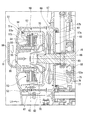
- FIG. 3 is an enlarged view of the installation part of the ACG starter 50 of FIG.
- the ACG starter 50 includes a bottomed cylindrical rotor 52 attached to the end of the crankshaft 16, and a stator 53 disposed on the inner peripheral side of the rotor 52.
- the rotor 52 is fixed to the crankshaft 16 so that the bottom wall 52a is positioned on the side wall side of the crankcase 17.
- the stator 53 is fixed to the inner surface of the bottom wall 51a of the engine cover 51 by bolt fastening or the like.
- the permanent magnet 54 On the inner peripheral surface of the rotor 52, permanent magnets 54 are attached so that different magnetic pole faces (N-pole face and S-pole face) directed in the axial direction of the rotor 52 appear alternately along the circumferential direction.
- the permanent magnet 54 is disposed on the inner peripheral side of the rotor 52 such that the magnetization direction is along the radial direction of the rotor 52.
- the permanent magnet 54 has a plurality of strip-shaped magnet pieces attached to the inner peripheral surface of the rotor 52.
- the permanent magnet 54 is made of a cylindrical ferromagnetic material and has different magnetic pole surfaces along the circumferential direction. It may be magnetized so as to appear alternately.
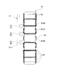
- FIG. 4 is a view of the stator 53 as seen from a direction orthogonal to the axis of the rotor 52.
- FIG. 5 is a view of the stator 53 as viewed from the direction along the axis of the rotor 52.
- the stator 53 has a plurality of teeth 55 protruding in the radial direction, and each of the teeth 55 is wound with a coil 56 of any of U phase, V phase, and W phase. .
- the tip surface of each tooth 55 is opposed to the magnetic pole surface of the permanent magnet 54 on the inner periphery of the rotor 52 with a small gap.
- each Hall IC unit 57 is attached on the inner side surface of the bottom wall 51a of the engine cover 51.
- each Hall IC unit 57 is arranged at a position close to the U-phase, V-phase, and W-phase magnetic poles (the teeth 55) of the stator 53.
- each Hall IC unit 57 has a structure in which a Hall IC element 57a is embedded in a resin 57b.
- one Hall IC element 57a corresponding to one package resin 57b of each Hall IC unit 57 is embedded, but there are three for the U phase, V phase, and W phase.
- the Hall IC element 57a may be embedded in the resin 57b as one package.
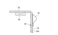
- each Hall IC unit 57 is attached to the bottom wall 51 a of the engine cover 51 so that the magnetic flux detection direction is along the radial direction of the rotor 52. As shown in FIG. 3, the Hall IC unit 57 attached to the bottom wall 51 a is opposed to the inner peripheral surface of the end edge of the rotor 52 without the permanent magnet 54. Each Hall IC unit 57 is disposed at a position facing the opening of the rotor 52 in the engine cover 51.
- Each Hall IC unit 57 constitutes a position detection sensor 58 for detecting the rotational position of the rotor 52 together with the permanent magnet 54 on the rotor 52 side.
- the signal detected by the position detection sensor 58 is output to a current control device (not shown) of the ACG starter 50, and the current control device controls energization of the U-phase, V-phase, and W-phase coils 56 (rotation). Used to control flow timing).
- a convex portion 61 is formed on the outer peripheral surface of the rotor 52 as a detection target for detecting the ignition timing of the engine 10.
- An electromagnetic pickup sensor 62 is attached to a position on the inner peripheral surface of the engine cover 51 that faces the rotation track of the convex portion 61.
- a detection signal detected by the pickup sensor 62 is output to a control device (not shown) for engine control.
- the detection signal detected by the pickup sensor 62 is also used to detect the rotation angle of the crankshaft 16 together with the signals detected by the three Hall IC units 57 described above.
- the pickup sensor 62 can detect the specific angle of the crankshaft 16 with respect to the engine cover 51, the pulses of the detection signal of each Hall IC unit 57 after the detection signal is output from the pickup sensor 62 are counted. Thus, it is possible to detect a plurality of angles starting from the specific angle of the crankshaft 16.
- an outside air introduction hole 69 is formed in the substantial center portion of the bottom wall 51 a of the engine cover 51 so as to face the end portion in the axial direction of the crankshaft 16.
- a wind guide duct 59 is installed on the vehicle outer side of the bottom wall 51a for taking the running wind into the engine cover 51 through the outside air introduction hole 69 when the vehicle is running.
- the wind guide duct 59 has a front end side for taking in outside air directed toward the front side of the vehicle body.
- a discharge port 60 for discharging the traveling wind introduced into the engine cover 51 to the outside is provided in a wall on the rear side of the crankshaft 16 of the engine cover 51.
- a disc-shaped partition wall 63 that separates the crank chamber 17a and the inner space of the engine cover 51 is attached to the opening 17b of the crankcase 17 from which the end of the crankshaft 16 projects.
- the partition wall 63 is formed of a heat resistant resin material. The outer peripheral edge of the partition wall 63 is fixed to the edge of the opening 17b of the crankcase 17 in a state where the O-ring 64 that is a seal member is sandwiched.
- a through hole 65 into which the end of the crankshaft 16 is inserted is formed at the center of the partition wall 63.
- An oil seal 66 is interposed between the through hole 65 and the outer peripheral surface of the crankshaft 16 to maintain the fluid tightness between the two while permitting rotation of the crankshaft 16.
- the rotor 52 of the ACG starter 50 is provided with a plurality of through holes 70 communicating with the bottom wall 52a on the front and back of the bottom wall 52a.
- a plurality of fins 67 project from the outer surface of the bottom wall 52 a of the rotor 52.
- the fins 67 function as rotating blades that suck cooling air from the outer peripheral area of the rotor 52 and the through hole 70 when the rotor 52 rotates and send the cooling air toward the partition wall 63.
- the fins 67 protruding from the bottom wall 52a of the rotor 52 constitute a forced cooling air guide member.
- FIG. 6 is a front view of the partition wall 63.
- arc-shaped rectifying blades that rectify the flow of cooling air sent from the fins 67 on the rotor 52 side 68 is protruded.
- the rectifying blades 68 of the present embodiment are disposed radially outside the position where the fins 67 on the rotor 52 side are formed, and overlap the fins 67 on the rotor 52 side in the axial direction.
- the cooling air when the cooling air is blown from the fins 67 to the front surface of the partition wall 63, the cooling air is guided to the vehicle body rear region along the front surface of the partition wall 63 by the guide function by the rectifying blades 68.
- the cooling air flowing along the front surface of the partition wall 63 is discharged to the outside of the engine cover 51 through the discharge port 60 after cooling the partition wall 63 and its peripheral area.
- the cooling air that has advanced to the partition wall 63 side through the through hole 70 receives the air blowing action by the fins 67 and cools the partition wall 63 and its peripheral area as described above.
- the cooling air that has advanced to the peripheral area of the Hall IC unit 57 cools the Hall IC unit 57 and then circulates to the outer periphery of the rotor 52. A part of the cooling air is directly discharged to the outside through the discharge port 60 and remains Is sucked to the front side of the partition wall 63 by receiving the suction and blowing action of the fins 67.
- the fin 67 which is a wind guide member provided on the bottom wall 52a of the rotor 52, is formed of a metal plate separate from the rotor 52 as in the second embodiment shown in FIG. You may make it fix to the bottom wall 52a of 52.
- the partition wall 63 is attached to the opening 17b of the crankcase 17 from which the end of the crankshaft 16 projects, and the space between the crank chamber 17a and the inner space of the engine cover 51 is defined. Since it is hermetically sealed, the lubricating oil flowing in the crankcase 17 is prevented from flowing into the engine cover 51. Therefore, the lubricating oil that has become hot during operation of the engine 10 does not enter the peripheral area of the Hall IC unit 57.
- the rotor 52 of the ACG starter 50 is attached to the crankshaft 16 such that the bottom wall 52 a is positioned on the crankcase 17 side, and the stator 53 and the Hall IC unit 57 of the ACG starter 50. Is attached to the inner surface of the bottom wall 51a of the engine cover 51, the stator 53 and the Hall IC unit 57 are kept in a low temperature state by the engine cover 51 that is directly exposed to the outside air and easily cooled.
- a plurality of fins 67 functioning as rotating blades are provided on the bottom wall 51 a of the rotor 52 that rotates integrally with the crankshaft 16.
- the cooling air introduced through the air can be blown onto the partition wall 63.
- the partition 63 and the wall of the crankcase 17 in the surrounding area can be efficiently cooled by the cooling air. Therefore, the heat on the crankcase 17 side is more difficult to be transmitted to the Hall IC unit 57 side.
- the cooling air blown from the fins 67 on the rotor 52 side is guided to the rear side of the vehicle body along the front surface of the partition wall 63 on the surface on the partition wall 63 side facing the bottom wall 52 a of the rotor 52. Since the rectifying blades 68 project, the partition wall 63 exposed to the heat on the crankcase 17 side can be cooled more efficiently by the cooperation of the fins 67 and the rectifying blades 68.
- a part of the traveling wind introduced into the engine cover 51 through the air guide duct 59 flows directly into the front surface side of the partition wall 63 through the through hole 70 of the rotor 52, and A part of the remainder flows into the peripheral area of the Hall IC unit 57 in the opening of the rotor 52, and this traveling wind is discharged to the outside from the discharge port 60 after cooling the partition wall 63 and the Hall IC unit 57.
- the portion of the engine cover 51 that is likely to become hot can be more efficiently cooled by the traveling wind.
- the traveling wind taken into the engine cover 51 from the air guide duct 59 also cools the pickup sensor 62 attached to the inner surface of the peripheral wall of the engine cover 51.
- the Hall IC unit 57 is attached to a portion of the U-phase, V-phase, and W-phase magnetic poles of the stator 53 that directly faces the magnetic pole surface of the permanent magnet 54.
- each Hall IC unit 57 has a magnetic flux detection direction parallel to the magnetization direction of the permanent magnet 54 on the side portion in the axial direction of the permanent magnet 54 magnetized along the radial direction of the rotor 52. Since it is arranged (along the radial direction of the rotor 52), the magnetic flux change of each magnetic pole of the stator 53 accompanying the movement of the permanent magnet 54 can be detected efficiently.
- the Hall IC unit 57 since the Hall IC unit 57 is disposed close to the inner peripheral surface of the end edge of the rotor 52, the magnetic flux change of each magnetic pole of the stator 53 can be detected more efficiently. .
- the change in the magnetic flux corresponding to each of the U, V, and W phases can be detected by the Hall IC unit 57 as described above, and the convex portion 61 that protrudes from the outer periphery of the rotor 52.
- the ignition timing of the engine 10 can be detected by the pickup sensor 62 provided on the peripheral wall of the engine cover 51, and based on the detection signal of the pickup sensor 62 and the detection signal of each Hall IC unit 57.
- the rotation angle of the crankshaft 16 can be detected. Since both the Hall IC unit 57 and the pickup sensor 62 are not easily affected by the heat on the crankcase 17 side as described above, stable detection performance can always be maintained.
- the rotation angle of the crankshaft 16 detected based on the detection signals of the pickup sensor 62 and each Hall IC unit 57 is, for example, the stop position (angle) of the crankshaft 16 at the next engine 10 at the time of idling stop. This is used when the ACG starter 50 is rotationally controlled so as to be in a position suitable for restarting the ACG.
- the partition wall 63 attached to the opening 17b of the crankcase 17 is formed of a heat-resistant resin material, so that high heat on the crankcase 17 side is efficiently blocked by the partition wall 63.
- an air guide portion such as a rectifying blade 68 can be easily formed integrally with the partition wall 63.
- FIG. 8 is an enlarged view showing an installation part of the ACG starter 50 according to the third embodiment of the present invention.
- the basic configuration of the engine unit of this embodiment is substantially the same as that of the first embodiment.
- the fins 67 functioning as rotating blades are integrated with the bottom wall 52 a of the rotor 52.
- the difference is that the rotor 52 and a separate rotating blade 77 are integrally attached to the crankshaft 16.
- the rotary blade 77 is formed by projecting a plurality of fins 67 on a disk-shaped support plate 75 fixed to the crankshaft 16, and is positioned in a space portion between the bottom wall 52 a of the rotor 52 and the partition wall 63. As shown in FIG.
- the rotary blade 77 constitutes an air guide member that guides cooling air into the space between the bottom wall 52 a of the rotor 52 and the partition wall 63. Further, on the front surface side of the partition wall 63, a rectifying blade 68 is projected in the same manner as in the first embodiment.
- the rectifying blades 68 are arranged radially outside the rotating blades 77 and overlap the rotating blades 77 in the axial direction.
- the engine unit of this embodiment can basically obtain substantially the same effect as that of the first embodiment, but does not require any special processing on the rotor 52 or the partition wall 63 and rotates on the crankshaft 16. Since it is only necessary to attach the blades 77, the manufacturing is easy and the parts of the existing vehicle type can be used as they are, which has the further advantage that the manufacturing cost can be reduced.
- the partition wall 63 may be provided with a rectifying blade 68 that rectifies the flow of the cooling air sent from the rotary blade 77 as in the first embodiment.
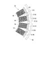
- FIG. 9 is a diagram schematically illustrating the inner peripheral surface of the rotor 52 according to the fourth embodiment of the present invention.
- FIG. 10 is a schematic enlarged cross-sectional view of the installation part of the ACG starter 50 corresponding to FIG. 3 of the fourth embodiment.
- FIG. 11 is a view of the stator 53 as viewed from the direction along the axis of the rotor 52.
- the engine unit of the fourth embodiment does not employ the pickup sensor 62 shown in FIGS. 3 and 8 in order to detect the ignition timing of the engine, and a detection target for a part of the permanent magnet 54 of the ACG starter 50.
- Index magnet 91 (permanent magnet) is attached, and the Hall IC unit 57A detects the magnetic flux change of the magnet array including the index magnet 91.
- the magnet array of the permanent magnets 54 including the indicator magnet 91 and the Hall IC unit 57 ⁇ / b> A constitute a position detection sensor 58 ⁇ / b> A that detects the rotational position of the rotor 52.
- the permanent magnet 54 and the Hall IC units 57 for U phase, V phase, and W phase (hereinafter referred to as “Hall IC unit 57 for energization control”) are other than those described above.
- the position detection sensor 58 is configured similarly to the embodiment.
- the permanent magnets 54 installed on the inner peripheral surface of the rotor 52 are arranged so that the magnetized surfaces alternately appear along the circumferential direction as in the other embodiments described above.
- Each Hall IC unit 57 for energization control is attached to the inner surface of the bottom wall 51 a of the engine cover 51 at a lateral position of the U-phase, V-phase, and W-phase magnetic poles and the permanent magnet 54.
- the Hall IC elements of the Hall IC units 57 for energization control are arranged so that the magnetic flux detection direction is along the radial direction of the rotor 52.
- the indicator magnet 91 is arranged such that a magnetic pole different from the magnetic pole facing the rotor center side of the permanent magnet 54 is directed to the rotor center side at the end of the arbitrary magnet piece of the permanent magnet 54 (for example, permanent magnet 54). If the magnetic pole of the magnet 54 is the S pole, the N pole is attached to the rotor center side). In the magnet row on the one end side in the axial direction including the indicator magnet 91, three same magnetic poles (N poles in the example of FIG. 9) are arranged in series before and after the indicator magnet 91.
- the specific position (angle) on the crankshaft 16 is determined. Can do.
- the specific position on the crankshaft 16 is made to correspond to the ignition position of the engine.
- the Hall IC unit 57A for detecting the ignition timing is attached to the inner side surface of the bottom wall 51a of the engine cover 51, like the Hall IC unit 57 for controlling energization.
- a magnetic flux guide member 92 such as a magnetic metal is disposed at a position facing the passing track of the magnetic pole surface of the indicator magnet 91 with a minute gap.
- the magnetic flux guiding member 92 is disposed so that one end faces the passing track of the magnetic pole surface of the indicator magnet 91 and the other end faces the magnetic flux detecting portion of the Hall IC unit 57A.
- the engine unit of the fourth embodiment can detect the ignition timing of the engine by the magnet array at the end of the permanent magnet 54 including the indicator magnet 91 and the Hall IC unit 57A, and can also be used for controlling the energization of the Hall IC unit 57A.
- the rotation angle of the crankshaft 16 can be accurately detected using the output signal of each Hall IC unit 57.
- each Hall IC unit 57 for energization control but also the Hall IC unit 57A for detecting the ignition timing can be efficiently cooled in the same manner as in the first embodiment. Therefore, in this engine unit, since the cooling performance of the installation portion of the Hall IC units 57 and 57A is enhanced, even if high cooling efficiency cannot be expected on the engine body side, the Hall IC units 57 and 57A are stable. Rotational position detection can be obtained.
- the partition wall 63 that closes the opening 17b of the crankcase 17 is formed of a heat-resistant resin, but the partition wall 63 may be formed of a metal material. In this case, heat generated on the crankcase 17 side is more easily dissipated to the outside through the partition wall 63, and it is possible to consider cooling the engine itself using the air guide portion.
Abstract
Description
本願は、2013年2月28日に出願された特願2013-39617号に基づき優先権を主張し、その内容をここに援用する。
この種の用途で交流発電用の回転電機を用いる場合には、回転電機を円滑に駆動させるために、ロータ上の永久磁石の移動位置に応じてステータ側のU相,V相,W相の各磁極のコイルに適正なタイミングで通電を行う必要がある。このため、この種の用途で用いられる回転電機においては、ロータの回転位置を検出するための位置検出センサが設けられている(例えば、特許文献1参照。)。
また、この特許文献1に記載の回転電機の場合、有底円筒状のロータが、そのロータの開口側がクランクケース側を向くようにしてクランク軸の端部に取り付けられており、ステータとそのステータに付設されるホールICユニットとはクランクケースの壁部の外側面に取り付けられている。ステータやロータは、クランクケースの壁部に取り付けられるエンジンカバーによってこれらの外側を覆われている。
(1)本発明の一態様に係るエンジンユニットのセンサ設置構造は、クランク軸を収容するクランク室と前記クランク軸の端部が突出する開口とを有するクランクケースと;前記開口から突出した前記クランク軸の前記端部に取り付けられる有底円筒状のロータと前記ロータに近接する非回転部に取り付けられるステータとを有する回転電機と;前記ロータの回転位置を検出する位置検出センサと;前記クランクケースの前記開口のある壁部に取り付けられて前記クランク軸の前記端部と前記回転電機の外側を覆うエンジンカバーと;前記位置検出センサが、前記ロータに設けられた永久磁石と;前記ロータ上の前記永久磁石の回転位置に応じた磁束の変化を検出するホールICユニットと;を備え、前記クランクケースの前記開口に、前記クランク室と前記エンジンカバーの内側空間とを隔成する隔壁が設けられ、前記ロータは、前記クランク軸の前記端部に、底壁が前記クランクケース側に位置されるように取り付けられ、前記回転電機の前記ステータと前記位置検出センサの前記ホールICユニットとが前記エンジンカバーに取り付けられ、前記ロータと前記隔壁の間に、前記ロータの前記底壁と前記隔壁の間の空間に冷却風を誘導するための強制冷却用の導風部材が設けられている。
これにより、クランク室とエンジンカバーの内側空間の間が隔壁によって仕切られ、クランクケース内を流動する高温の潤滑オイルがエンジンカバー内に流入するのを規制される。また、ステータとホールICユニットは、外気に晒されて冷却され易いエンジンカバーに取り付けられていることから、温度上昇を抑制できる。また、ロータの底壁と隔壁の間の空間部には、導風部材によって強制冷却風が導入され、エンジンカバーの内側に臨む隔壁の周辺部が強制冷却風によって冷却される。この結果、クランクケース側の熱がホールICユニット側に伝達されにくくなる。
これにより、回転羽根と整流羽根との協働により、隔壁の前面側において、冷却風を効率良く流動させることが可能になる。
これにより、車両の走行時には、走行風が導風ダクトを通してエンジンカバー内のクランク軸に対向する方向に導入され、その走行風の一部が、ロータの底壁の貫通孔を通して隔壁方向に直接流入し、残余の走行風が、ロータの底壁で向きを変えてホールICユニットの周域方向に流れる。貫通孔から隔壁方向に流入した走行風は、隔壁を冷却した後に、排出口からエンジンカバーの外部に排出される。また、ホールICユニットの周域に流れ込んだ走行風は、ホールICユニットを冷却した後に、ロータの周壁の外側に回り込んで排出口からエンジンカバーの外部に排出される。
これにより、ロータ側の永久磁石がU相,V相,W相の各磁極の近傍を通過するタイミングがホールICユニットのホールIC素子を通して検出されることになる。
これにより、ピックアップセンサの検出信号を基にしてエンジンの点火タイミングが検出されるようになるとともに、ピックアップセンサの検出信号と各ホールIC素子の検出信号とを組み合わせることによって、クランク軸の回転角度も検出可能となる。
これにより、クランクケース側からエンジンカバー側に伝達されようとする熱を隔壁が遮断するようになる。また、隔壁には導風部を形成し易くなる。
(車両構成)
図1は、エンジンユニット2を搭載した自動二輪車1の側面を示す図である。
自動二輪車1は、エンジンユニット2が車体前後方向の中央に搭載され、エンジンユニット2の後部上方に乗員が着座するシート3が設けられ、シート3の下方に燃料タンク4が設けられている。
前輪Wfは、フロントフォーク5に回転可能に支持され、フロントフォーク5の上部に操舵ハンドル6が設けられている。後輪Wrは、スイングアーム7を介して車体フレームに揺動可能に支持されている。
図2は、図1のA-A断面に対応するエンジンユニット2の断面図である。
エンジンユニット2は、内燃機関であるレシプロ式のエンジン10と、多段式の変速機11が一体ブロックとして構成され、エンジン10と変速機11が遠心クラッチ8とミッションクラッチ12を介して動力伝達可能とされている。
図2に示すように、燃焼室19内に臨むようにシリンダヘッド20には点火装置21が設置される。シリンダヘッド20の端部には動弁装置22が設けられる。動弁装置22は、クランク軸16と連動して図示しない吸排気バルブを開閉駆動する。クランク軸16上のコンロッド15との連結部(クランクピン)の軸方向両側にはクランクウェブ23が設けられる。クランクケース17内のクランク室17aは、クランク軸16の実質的に全域を収容する。
また、クラッチアウタ25には、ミッションクラッチ12の入力ギヤ27と噛合する出力ギヤ28が一体回転可能に結合されている。
変速機11では、クランクケース17内に設けられた図示しないシフトドラムの回動操作によってメイン変速ギヤ群M1とカウンタギヤ群M2の駆動伝達ギヤが選択され、それによってニュートラルを含む任意の変速ギヤ段(ギヤポジション)が設定される。
ACGスタータ50は、クランク軸16の端部に取り付けられる有底円筒状のロータ52と、ロータ52の内周側に配置されるステータ53と、を備えている。ロータ52は、底壁52aがクランクケース17の側壁側に位置されるようにクランク軸16に固定される。ステータ53は、エンジンカバー51の底壁51aの内側面にボルト締結等によって固定されている。
これらの図に示すように、ステータ53は、放射方向に突出する複数のティース55を有し、その各ティース55にU相,V相,W相のいずれかのコイル56が巻回されている。各ティース55の先端面は、ロータ52の内周の永久磁石54の磁極面に微小隙間をもって対峙するようになっている。
なお、本実施形態においては、各ホールICユニット57の一パッケージの樹脂57bに対応するホールIC素子57aが一つずつ埋設されているが、U相用,V相用,W相用の3つのホールIC素子57aを一パッケージとして樹脂57b内に埋設するようにしても良い。
ピックアップセンサ62で検出される検出信号は、前述の3つのホールICユニット57で検出される各信号と併せてクランク軸16の回転角を検出するのにも用いられる。すなわち、ピックアップセンサ62では、エンジンカバー51に対するクランク軸16の特定角度を検出することができるため、ピックアップセンサ62から検出信号が出力されてからの各ホールICユニット57の検出信号のパルスをカウントすることにより、クランク軸16の特定角度を起点とした複数ヶ所の角度を検出することができる。
エンジンカバー51の底壁51aの実質的中央部には、図3に示すように、クランク軸16の軸方向の端部と対向するように外気導入孔69が形成される。底壁51aの車外側には、車両走行時に走行風を外気導入孔69を通してエンジンカバー51内に取り入れるための導風ダクト59が取り付けられている。導風ダクト59は、外気を取り入れる先端部側が車体前方側に指向している。また、エンジンカバー51のクランク軸16よりも後方側の壁には、エンジンカバー51内に導入された走行風を外部に排出するための排出口60が設けられている。
図3,図6に示すように、隔壁63のロータ52の底壁52aと対向する側の面には、ロータ52側のフィン67から送られた冷却風の流れを整流する円弧状の整流羽根68が突設されている。本実施形態の整流羽根68は、ロータ52側のフィン67の形成位置よりも径方向外側に配置されるとともに、ロータ52側のフィン67と軸方向で相互にオーバーラップする。このため、フィン67から隔壁63の前面に冷却風が吹き付けられると、冷却風は、整流羽根68による案内機能により、隔壁63の前面に沿って車体後方領域に誘導される。このように隔壁63の前面に沿って流れる冷却風は、隔壁63とその周域部を冷却した後に排出口60を通してエンジンカバー51の外部に排出される。
なお、導風ダクト59からエンジンカバー51内に取り入れられた走行風は、エンジンカバー51の周壁の内面に取り付けられたピックアップセンサ62も冷却する。
なお、ピックアップセンサ62と各ホールICユニット57の各検出信号を基にして検出されるクランク軸16の回転角度は、例えば、アイドルストップ時に、クランク軸16の停止位置(角度)が次のエンジン10の再始動に適した位置になるように、ACGスタータ50を回転制御する場合に用いられる。
本実施形態のエンジンユニットは、基本的な構成は第1の実施形態と実質的に同様であるが、第1の実施形態では、回転羽根として機能するフィン67がロータ52の底壁52aに一体に設けられているのに対し、ロータ52と別体の回転羽根77がクランク軸16に一体に取り付けられている点が異なっている。
回転羽根77は、クランク軸16に固定される円板状の支持板75に複数のフィン67が突設されたものであり、ロータ52の底壁52aと隔壁63の間の空間部に位置されるように、クランク軸16上に取り付けられている。
本実施形態の場合、回転羽根77がロータ52の底壁52aと隔壁63の間の空間部に冷却風を誘導する導風部材を構成している。
また、隔壁63の前面側には、第1の実施形態と同様に整流羽根68が突設されている。整流羽根68は、回転羽根77よりも径方向外側に配置されるとともに、回転羽根77に対して軸方向でオーバーラップするようになっている。
なお、隔壁63には、第1の実施形態と同様に、回転羽根77から送られた冷却風の流れを整流する整流羽根68を設けるようにしても良い。
第4の実施形態のエンジンユニットは、エンジンの点火タイミングを検出するために、図3,図8に示すピックアップセンサ62を採用せずに、ACGスタータ50の永久磁石54の一部に検出ターゲット用の指標磁石91(永久磁石)を付設し、その指標磁石91を含む磁石列の磁束変化をホールICユニット57Aによって検出するようにしている。本実施形態では、指標磁石91を含む永久磁石54の磁石列とホールICユニット57Aが、ロータ52の回転位置を検出する位置検出センサ58Aを構成している。なお、本実施形態の場合、永久磁石54とU相用,V相用,W相用の各ホールICユニット57(以下、「通電制御用のホールICユニット57」と呼ぶ。)は上記の他の実施形態と同様に位置検出センサ58を構成している。
また、本実施形態の場合、ロータ52の外周壁に、エンジンの点火タイミングを検出するためのターゲット用の凸部を加工する必要がないため、製造コストの削減が可能になるという利点もある。
Claims (9)
- クランク軸を収容するクランク室と前記クランク軸の端部が突出する開口とを有するクランクケースと;
前記開口から突出した前記クランク軸の前記端部に取り付けられる有底円筒状のロータと前記ロータに近接する非回転部に取り付けられるステータとを有する回転電機と;
前記ロータの回転位置を検出する位置検出センサと;
前記クランクケースの前記開口のある壁部に取り付けられて前記クランク軸の前記端部と前記回転電機の外側を覆うエンジンカバーと;
前記位置検出センサが、前記ロータに設けられた永久磁石と;
前記ロータ上の前記永久磁石の回転位置に応じた磁束の変化を検出するホールICユニットと;を備え、
前記クランクケースの前記開口に、前記クランク室と前記エンジンカバーの内側空間とを隔成する隔壁が設けられ、
前記ロータは、前記クランク軸の前記端部に、底壁が前記クランクケース側に位置されるように取り付けられ、
前記回転電機の前記ステータと前記位置検出センサの前記ホールICユニットとが前記エンジンカバーに取り付けられ、
前記ロータと前記隔壁の間に、前記ロータの前記底壁と前記隔壁の間の空間に冷却風を誘導するための強制冷却用の導風部材が設けられているエンジンユニットのセンサ設置構造。 - 前記導風部材は、前記ロータの前記底壁に設けられた回転羽根である請求項1に記載のエンジンユニットのセンサ設置構造。
- 前記導風部材は、前記クランク軸に一体的に取り付けられた回転羽根である請求項1に記載のエンジンユニットのセンサ設置構造。
- 前記隔壁の前記ロータの前記底壁に臨む側の面には、前記回転羽根から送られた冷却風の流れを整流する整流羽根が突設されている請求項2または3に記載のエンジンユニットのセンサ設置構造。
- 前記ホールICユニットは、前記エンジンカバー内の前記ロータの開口内に対峙する位置に設置され、
前記エンジンカバーには、車体前方側に指向し、走行風を前記エンジンカバー内の前記クランク軸の軸方向の前記端部に対向する方向に導入する導風ダクトと、前記導風ダクトから前記エンジンカバー内に導入された走行風を、前記クランク軸よりも後方側から前記エンジンカバーの外部に排出する排出口と、が設けられ、
前記ロータの前記底壁には、前記導風ダクトから導入された走行風の一部を前記隔壁側に導入する貫通孔が設けられている請求項1~4のいずれか1項に記載のエンジンユニットのセンサ設置構造。 - 前記永久磁石は、磁化方向が前記ロータの半径方向に沿うように前記ロータに配置され、
前記ホールICユニットは、磁束検出方向が前記ロータの前記半径方向に沿うように前記エンジンカバーに取り付けられている請求項1~5のいずれか1項に記載のエンジンユニットのセンサ設置構造。 - 前記ロータに設けられる前記永久磁石は、異なる磁極面が前記ロータの円周方向に沿って交互に現れるように着磁され、回転電機として機能するときに、前記ステータのU相,V相,W相の各磁極との間で磁束の入出が行われる永久磁石であり、
前記ホールICユニットは、前記U相,前記V相,前記W相の各磁極の磁束の変化を検出するホールIC素子を備えている請求項1~6のいずれか1項に記載のエンジンユニットのセンサ設置構造。 - 前記ロータの外周面には、エンジンの点火タイミング検出用の凸部が設けられ、前記エンジンカバー内の前記凸部の通過軌道に対向する位置には、ピックアップセンサが配置されている請求項7に記載のエンジンユニットのセンサ設置構造。
- 前記隔壁は、樹脂材料によって形成されている請求項1~8のいずれか1項に記載のエンジンユニットのセンサ設置構造。
Priority Applications (2)
| Application Number | Priority Date | Filing Date | Title |
|---|---|---|---|
| EP14757362.0A EP2963784B1 (en) | 2013-02-28 | 2014-01-27 | Structure for installing sensor in engine unit |
| JP2015502810A JP5942035B2 (ja) | 2013-02-28 | 2014-01-27 | エンジンユニットのセンサ設置構造 |
Applications Claiming Priority (2)
| Application Number | Priority Date | Filing Date | Title |
|---|---|---|---|
| JP2013039617 | 2013-02-28 | ||
| JP2013-039617 | 2013-02-28 |
Publications (1)
| Publication Number | Publication Date |
|---|---|
| WO2014132719A1 true WO2014132719A1 (ja) | 2014-09-04 |
Family
ID=51427993
Family Applications (1)
| Application Number | Title | Priority Date | Filing Date |
|---|---|---|---|
| PCT/JP2014/051660 WO2014132719A1 (ja) | 2013-02-28 | 2014-01-27 | エンジンユニットのセンサ設置構造 |
Country Status (3)
| Country | Link |
|---|---|
| EP (1) | EP2963784B1 (ja) |
| JP (1) | JP5942035B2 (ja) |
| WO (1) | WO2014132719A1 (ja) |
Cited By (4)
| Publication number | Priority date | Publication date | Assignee | Title |
|---|---|---|---|---|
| JP2019174380A (ja) * | 2018-03-29 | 2019-10-10 | 本田技研工業株式会社 | クランク角検出装置 |
| WO2022219693A1 (ja) * | 2021-04-13 | 2022-10-20 | 日産自動車株式会社 | 内燃機関のダンパ冷却構造 |
| DE102022121890A1 (de) | 2021-09-02 | 2023-03-02 | Kawasaki Motors, Ltd. | Motoreinheit |
| EP4275939A1 (en) | 2022-05-12 | 2023-11-15 | Kawasaki Motors, Ltd. | Vehicle and cooling structure for electrical component |
Families Citing this family (2)
| Publication number | Priority date | Publication date | Assignee | Title |
|---|---|---|---|---|
| JP2018066339A (ja) * | 2016-10-20 | 2018-04-26 | ヤマハ発動機株式会社 | エンジン |
| FR3087966B1 (fr) * | 2018-10-26 | 2021-08-20 | Valeo Equip Electr Moteur | Bloc de commande d'une machine electrique tournante et procede de montage d'un tel bloc de commande |
Citations (3)
| Publication number | Priority date | Publication date | Assignee | Title |
|---|---|---|---|---|
| JP2010200421A (ja) | 2009-02-23 | 2010-09-09 | Mitsuba Corp | アウタロータ型の回転電機 |
| JP2011149277A (ja) * | 2010-01-19 | 2011-08-04 | Honda Motor Co Ltd | 鞍乗型車両 |
| JP2013039617A (ja) | 2011-07-15 | 2013-02-28 | Showarasenkan Seisakusho Co Ltd | バルジ加工用の金属ベローズ成形方法、及び、その金属ベローズ成形装置 |
Family Cites Families (6)
| Publication number | Priority date | Publication date | Assignee | Title |
|---|---|---|---|---|
| JPH0691718B2 (ja) * | 1990-06-01 | 1994-11-14 | 株式会社三ツ葉電機製作所 | 磁石発電機の冷却ファンおよびその製造方法 |
| JPH0578175U (ja) * | 1992-03-17 | 1993-10-22 | 富士重工業株式会社 | エンジン駆動ゼネレータ |
| JP4020275B2 (ja) * | 1997-10-22 | 2007-12-12 | 株式会社ミツバ | 電動機兼用発電機 |
| WO2001038728A1 (fr) * | 1999-11-24 | 2001-05-31 | Mitsuba Corporation | Demarreur, dispositif de commande de demarrage et detecteur d'angle de vilebrequin d'un moteur a combustion interne |
| JP2005104248A (ja) * | 2003-09-29 | 2005-04-21 | Honda Motor Co Ltd | ハイブリッド車両におけるパワーユニット |
| JP2013027252A (ja) * | 2011-07-25 | 2013-02-04 | Denso Trim Kk | 始動発電機 |
-
2014
- 2014-01-27 JP JP2015502810A patent/JP5942035B2/ja not_active Expired - Fee Related
- 2014-01-27 EP EP14757362.0A patent/EP2963784B1/en active Active
- 2014-01-27 WO PCT/JP2014/051660 patent/WO2014132719A1/ja active Application Filing
Patent Citations (3)
| Publication number | Priority date | Publication date | Assignee | Title |
|---|---|---|---|---|
| JP2010200421A (ja) | 2009-02-23 | 2010-09-09 | Mitsuba Corp | アウタロータ型の回転電機 |
| JP2011149277A (ja) * | 2010-01-19 | 2011-08-04 | Honda Motor Co Ltd | 鞍乗型車両 |
| JP2013039617A (ja) | 2011-07-15 | 2013-02-28 | Showarasenkan Seisakusho Co Ltd | バルジ加工用の金属ベローズ成形方法、及び、その金属ベローズ成形装置 |
Cited By (9)
| Publication number | Priority date | Publication date | Assignee | Title |
|---|---|---|---|---|
| JP2019174380A (ja) * | 2018-03-29 | 2019-10-10 | 本田技研工業株式会社 | クランク角検出装置 |
| CN110318871A (zh) * | 2018-03-29 | 2019-10-11 | 本田技研工业株式会社 | 曲柄角检测装置 |
| US11035698B2 (en) | 2018-03-29 | 2021-06-15 | Honda Motor Co., Ltd. | Crank angle detection device |
| CN110318871B (zh) * | 2018-03-29 | 2021-06-29 | 本田技研工业株式会社 | 曲柄角检测装置 |
| WO2022219693A1 (ja) * | 2021-04-13 | 2022-10-20 | 日産自動車株式会社 | 内燃機関のダンパ冷却構造 |
| JP7480913B2 (ja) | 2021-04-13 | 2024-05-10 | 日産自動車株式会社 | 内燃機関のダンパ冷却構造 |
| DE102022121890A1 (de) | 2021-09-02 | 2023-03-02 | Kawasaki Motors, Ltd. | Motoreinheit |
| US11761368B2 (en) | 2021-09-02 | 2023-09-19 | Kawasaki Motors, Ltd. | Engine unit |
| EP4275939A1 (en) | 2022-05-12 | 2023-11-15 | Kawasaki Motors, Ltd. | Vehicle and cooling structure for electrical component |
Also Published As
| Publication number | Publication date |
|---|---|
| EP2963784B1 (en) | 2018-10-10 |
| EP2963784A1 (en) | 2016-01-06 |
| JPWO2014132719A1 (ja) | 2017-02-02 |
| JP5942035B2 (ja) | 2016-06-29 |
| EP2963784A4 (en) | 2017-01-11 |
Similar Documents
| Publication | Publication Date | Title |
|---|---|---|
| JP5942035B2 (ja) | エンジンユニットのセンサ設置構造 | |
| JP2001238426A (ja) | モータ | |
| JP5953423B2 (ja) | 発電電動ユニット、動力出力機関、および車両 | |
| JP2008193841A (ja) | アキシャルギャップ型回転電機付きエンジン | |
| US9735653B2 (en) | Rotary electric device for power working machine | |
| JP2009159792A (ja) | 車両の駆動装置、及びそれを備える鞍乗型車両 | |
| JP6007951B2 (ja) | 回転電機 | |
| TWI527345B (zh) | 旋轉電機及跨坐型車輛 | |
| US8453815B2 (en) | Friction clutch and drive system for cooling an internal combustion engine of a vehicle with a friction clutch | |
| JP4003926B2 (ja) | クラッチケースのセンサ取付構造 | |
| JP5990479B2 (ja) | エンジンユニットのセンサ設置構造 | |
| JP2014105626A (ja) | 鞍乗り型車両 | |
| JP2019054559A (ja) | ビークル | |
| EP3312420B1 (en) | Engine | |
| JP3930246B2 (ja) | ブラシレス多相交流電機およびその通電制御装置 | |
| JP3974637B2 (ja) | エンジンの複合動力装置 | |
| JP2015218625A (ja) | エンジンユニットおよび鞍乗り型車両 | |
| JP6123640B2 (ja) | 機電一体型エンジン始動装置 | |
| JP2014168344A (ja) | クランク軸の位置検出構造 | |
| JP6014516B2 (ja) | クランク軸の位置検出構造 | |
| JP2009194983A (ja) | 回転電機 | |
| EP2599976A1 (en) | Device for transmitting the movement to fans for cooling engines with stoppage of the fan in an idle condition thereof | |
| JP2014177868A (ja) | 車両の電動発電機 | |
| JP6041567B2 (ja) | 車両用内燃機関 | |
| JP2005224063A (ja) | 発電装置における空冷装置 |
Legal Events
| Date | Code | Title | Description |
|---|---|---|---|
| 121 | Ep: the epo has been informed by wipo that ep was designated in this application |
Ref document number: 14757362 Country of ref document: EP Kind code of ref document: A1 |
|
| ENP | Entry into the national phase |
Ref document number: 2015502810 Country of ref document: JP Kind code of ref document: A |
|
| WWE | Wipo information: entry into national phase |
Ref document number: IDP00201505211 Country of ref document: ID |
|
| NENP | Non-entry into the national phase |
Ref country code: DE |
|
| WWE | Wipo information: entry into national phase |
Ref document number: 2014757362 Country of ref document: EP |