WO2014132539A1 - 車両の制御装置 - Google Patents
車両の制御装置 Download PDFInfo
- Publication number
- WO2014132539A1 WO2014132539A1 PCT/JP2013/084483 JP2013084483W WO2014132539A1 WO 2014132539 A1 WO2014132539 A1 WO 2014132539A1 JP 2013084483 W JP2013084483 W JP 2013084483W WO 2014132539 A1 WO2014132539 A1 WO 2014132539A1
- Authority
- WO
- WIPO (PCT)
- Prior art keywords
- vehicle
- power generation
- regenerative power
- amount
- generation amount
- Prior art date
Links
Images


Classifications
-
- F—MECHANICAL ENGINEERING; LIGHTING; HEATING; WEAPONS; BLASTING
- F02—COMBUSTION ENGINES; HOT-GAS OR COMBUSTION-PRODUCT ENGINE PLANTS
- F02B—INTERNAL-COMBUSTION PISTON ENGINES; COMBUSTION ENGINES IN GENERAL
- F02B37/00—Engines characterised by provision of pumps driven at least for part of the time by exhaust
- F02B37/12—Control of the pumps
-
- B—PERFORMING OPERATIONS; TRANSPORTING
- B60—VEHICLES IN GENERAL
- B60W—CONJOINT CONTROL OF VEHICLE SUB-UNITS OF DIFFERENT TYPE OR DIFFERENT FUNCTION; CONTROL SYSTEMS SPECIALLY ADAPTED FOR HYBRID VEHICLES; ROAD VEHICLE DRIVE CONTROL SYSTEMS FOR PURPOSES NOT RELATED TO THE CONTROL OF A PARTICULAR SUB-UNIT
- B60W20/00—Control systems specially adapted for hybrid vehicles
- B60W20/10—Controlling the power contribution of each of the prime movers to meet required power demand
- B60W20/13—Controlling the power contribution of each of the prime movers to meet required power demand in order to stay within battery power input or output limits; in order to prevent overcharging or battery depletion
-
- B—PERFORMING OPERATIONS; TRANSPORTING
- B60—VEHICLES IN GENERAL
- B60K—ARRANGEMENT OR MOUNTING OF PROPULSION UNITS OR OF TRANSMISSIONS IN VEHICLES; ARRANGEMENT OR MOUNTING OF PLURAL DIVERSE PRIME-MOVERS IN VEHICLES; AUXILIARY DRIVES FOR VEHICLES; INSTRUMENTATION OR DASHBOARDS FOR VEHICLES; ARRANGEMENTS IN CONNECTION WITH COOLING, AIR INTAKE, GAS EXHAUST OR FUEL SUPPLY OF PROPULSION UNITS IN VEHICLES
- B60K6/00—Arrangement or mounting of plural diverse prime-movers for mutual or common propulsion, e.g. hybrid propulsion systems comprising electric motors and internal combustion engines ; Control systems therefor, i.e. systems controlling two or more prime movers, or controlling one of these prime movers and any of the transmission, drive or drive units Informative references: mechanical gearings with secondary electric drive F16H3/72; arrangements for handling mechanical energy structurally associated with the dynamo-electric machine H02K7/00; machines comprising structurally interrelated motor and generator parts H02K51/00; dynamo-electric machines not otherwise provided for in H02K see H02K99/00
- B60K6/20—Arrangement or mounting of plural diverse prime-movers for mutual or common propulsion, e.g. hybrid propulsion systems comprising electric motors and internal combustion engines ; Control systems therefor, i.e. systems controlling two or more prime movers, or controlling one of these prime movers and any of the transmission, drive or drive units Informative references: mechanical gearings with secondary electric drive F16H3/72; arrangements for handling mechanical energy structurally associated with the dynamo-electric machine H02K7/00; machines comprising structurally interrelated motor and generator parts H02K51/00; dynamo-electric machines not otherwise provided for in H02K see H02K99/00 the prime-movers consisting of electric motors and internal combustion engines, e.g. HEVs
- B60K6/42—Arrangement or mounting of plural diverse prime-movers for mutual or common propulsion, e.g. hybrid propulsion systems comprising electric motors and internal combustion engines ; Control systems therefor, i.e. systems controlling two or more prime movers, or controlling one of these prime movers and any of the transmission, drive or drive units Informative references: mechanical gearings with secondary electric drive F16H3/72; arrangements for handling mechanical energy structurally associated with the dynamo-electric machine H02K7/00; machines comprising structurally interrelated motor and generator parts H02K51/00; dynamo-electric machines not otherwise provided for in H02K see H02K99/00 the prime-movers consisting of electric motors and internal combustion engines, e.g. HEVs characterised by the architecture of the hybrid electric vehicle
- B60K6/48—Parallel type
- B60K6/485—Motor-assist type
-
- B—PERFORMING OPERATIONS; TRANSPORTING
- B60—VEHICLES IN GENERAL
- B60L—PROPULSION OF ELECTRICALLY-PROPELLED VEHICLES; SUPPLYING ELECTRIC POWER FOR AUXILIARY EQUIPMENT OF ELECTRICALLY-PROPELLED VEHICLES; ELECTRODYNAMIC BRAKE SYSTEMS FOR VEHICLES IN GENERAL; MAGNETIC SUSPENSION OR LEVITATION FOR VEHICLES; MONITORING OPERATING VARIABLES OF ELECTRICALLY-PROPELLED VEHICLES; ELECTRIC SAFETY DEVICES FOR ELECTRICALLY-PROPELLED VEHICLES
- B60L1/00—Supplying electric power to auxiliary equipment of vehicles
-
- B—PERFORMING OPERATIONS; TRANSPORTING
- B60—VEHICLES IN GENERAL
- B60W—CONJOINT CONTROL OF VEHICLE SUB-UNITS OF DIFFERENT TYPE OR DIFFERENT FUNCTION; CONTROL SYSTEMS SPECIALLY ADAPTED FOR HYBRID VEHICLES; ROAD VEHICLE DRIVE CONTROL SYSTEMS FOR PURPOSES NOT RELATED TO THE CONTROL OF A PARTICULAR SUB-UNIT
- B60W10/00—Conjoint control of vehicle sub-units of different type or different function
- B60W10/04—Conjoint control of vehicle sub-units of different type or different function including control of propulsion units
- B60W10/06—Conjoint control of vehicle sub-units of different type or different function including control of propulsion units including control of combustion engines
-
- B—PERFORMING OPERATIONS; TRANSPORTING
- B60—VEHICLES IN GENERAL
- B60W—CONJOINT CONTROL OF VEHICLE SUB-UNITS OF DIFFERENT TYPE OR DIFFERENT FUNCTION; CONTROL SYSTEMS SPECIALLY ADAPTED FOR HYBRID VEHICLES; ROAD VEHICLE DRIVE CONTROL SYSTEMS FOR PURPOSES NOT RELATED TO THE CONTROL OF A PARTICULAR SUB-UNIT
- B60W10/00—Conjoint control of vehicle sub-units of different type or different function
- B60W10/04—Conjoint control of vehicle sub-units of different type or different function including control of propulsion units
- B60W10/08—Conjoint control of vehicle sub-units of different type or different function including control of propulsion units including control of electric propulsion units, e.g. motors or generators
-
- B—PERFORMING OPERATIONS; TRANSPORTING
- B60—VEHICLES IN GENERAL
- B60W—CONJOINT CONTROL OF VEHICLE SUB-UNITS OF DIFFERENT TYPE OR DIFFERENT FUNCTION; CONTROL SYSTEMS SPECIALLY ADAPTED FOR HYBRID VEHICLES; ROAD VEHICLE DRIVE CONTROL SYSTEMS FOR PURPOSES NOT RELATED TO THE CONTROL OF A PARTICULAR SUB-UNIT
- B60W20/00—Control systems specially adapted for hybrid vehicles
-
- F—MECHANICAL ENGINEERING; LIGHTING; HEATING; WEAPONS; BLASTING
- F02—COMBUSTION ENGINES; HOT-GAS OR COMBUSTION-PRODUCT ENGINE PLANTS
- F02B—INTERNAL-COMBUSTION PISTON ENGINES; COMBUSTION ENGINES IN GENERAL
- F02B37/00—Engines characterised by provision of pumps driven at least for part of the time by exhaust
- F02B37/12—Control of the pumps
- F02B37/18—Control of the pumps by bypassing exhaust from the inlet to the outlet of turbine or to the atmosphere
-
- F—MECHANICAL ENGINEERING; LIGHTING; HEATING; WEAPONS; BLASTING
- F02—COMBUSTION ENGINES; HOT-GAS OR COMBUSTION-PRODUCT ENGINE PLANTS
- F02D—CONTROLLING COMBUSTION ENGINES
- F02D41/00—Electrical control of supply of combustible mixture or its constituents
- F02D41/0002—Controlling intake air
- F02D41/0005—Controlling intake air during deceleration
-
- F—MECHANICAL ENGINEERING; LIGHTING; HEATING; WEAPONS; BLASTING
- F02—COMBUSTION ENGINES; HOT-GAS OR COMBUSTION-PRODUCT ENGINE PLANTS
- F02D—CONTROLLING COMBUSTION ENGINES
- F02D41/00—Electrical control of supply of combustible mixture or its constituents
- F02D41/0002—Controlling intake air
- F02D41/0007—Controlling intake air for control of turbo-charged or super-charged engines
-
- F—MECHANICAL ENGINEERING; LIGHTING; HEATING; WEAPONS; BLASTING
- F02—COMBUSTION ENGINES; HOT-GAS OR COMBUSTION-PRODUCT ENGINE PLANTS
- F02D—CONTROLLING COMBUSTION ENGINES
- F02D41/00—Electrical control of supply of combustible mixture or its constituents
- F02D41/02—Circuit arrangements for generating control signals
- F02D41/021—Introducing corrections for particular conditions exterior to the engine
-
- F—MECHANICAL ENGINEERING; LIGHTING; HEATING; WEAPONS; BLASTING
- F02—COMBUSTION ENGINES; HOT-GAS OR COMBUSTION-PRODUCT ENGINE PLANTS
- F02D—CONTROLLING COMBUSTION ENGINES
- F02D41/00—Electrical control of supply of combustible mixture or its constituents
- F02D41/02—Circuit arrangements for generating control signals
- F02D41/04—Introducing corrections for particular operating conditions
- F02D41/045—Detection of accelerating or decelerating state
-
- B—PERFORMING OPERATIONS; TRANSPORTING
- B60—VEHICLES IN GENERAL
- B60K—ARRANGEMENT OR MOUNTING OF PROPULSION UNITS OR OF TRANSMISSIONS IN VEHICLES; ARRANGEMENT OR MOUNTING OF PLURAL DIVERSE PRIME-MOVERS IN VEHICLES; AUXILIARY DRIVES FOR VEHICLES; INSTRUMENTATION OR DASHBOARDS FOR VEHICLES; ARRANGEMENTS IN CONNECTION WITH COOLING, AIR INTAKE, GAS EXHAUST OR FUEL SUPPLY OF PROPULSION UNITS IN VEHICLES
- B60K6/00—Arrangement or mounting of plural diverse prime-movers for mutual or common propulsion, e.g. hybrid propulsion systems comprising electric motors and internal combustion engines ; Control systems therefor, i.e. systems controlling two or more prime movers, or controlling one of these prime movers and any of the transmission, drive or drive units Informative references: mechanical gearings with secondary electric drive F16H3/72; arrangements for handling mechanical energy structurally associated with the dynamo-electric machine H02K7/00; machines comprising structurally interrelated motor and generator parts H02K51/00; dynamo-electric machines not otherwise provided for in H02K see H02K99/00
- B60K6/20—Arrangement or mounting of plural diverse prime-movers for mutual or common propulsion, e.g. hybrid propulsion systems comprising electric motors and internal combustion engines ; Control systems therefor, i.e. systems controlling two or more prime movers, or controlling one of these prime movers and any of the transmission, drive or drive units Informative references: mechanical gearings with secondary electric drive F16H3/72; arrangements for handling mechanical energy structurally associated with the dynamo-electric machine H02K7/00; machines comprising structurally interrelated motor and generator parts H02K51/00; dynamo-electric machines not otherwise provided for in H02K see H02K99/00 the prime-movers consisting of electric motors and internal combustion engines, e.g. HEVs
- B60K6/22—Arrangement or mounting of plural diverse prime-movers for mutual or common propulsion, e.g. hybrid propulsion systems comprising electric motors and internal combustion engines ; Control systems therefor, i.e. systems controlling two or more prime movers, or controlling one of these prime movers and any of the transmission, drive or drive units Informative references: mechanical gearings with secondary electric drive F16H3/72; arrangements for handling mechanical energy structurally associated with the dynamo-electric machine H02K7/00; machines comprising structurally interrelated motor and generator parts H02K51/00; dynamo-electric machines not otherwise provided for in H02K see H02K99/00 the prime-movers consisting of electric motors and internal combustion engines, e.g. HEVs characterised by apparatus, components or means specially adapted for HEVs
- B60K6/26—Arrangement or mounting of plural diverse prime-movers for mutual or common propulsion, e.g. hybrid propulsion systems comprising electric motors and internal combustion engines ; Control systems therefor, i.e. systems controlling two or more prime movers, or controlling one of these prime movers and any of the transmission, drive or drive units Informative references: mechanical gearings with secondary electric drive F16H3/72; arrangements for handling mechanical energy structurally associated with the dynamo-electric machine H02K7/00; machines comprising structurally interrelated motor and generator parts H02K51/00; dynamo-electric machines not otherwise provided for in H02K see H02K99/00 the prime-movers consisting of electric motors and internal combustion engines, e.g. HEVs characterised by apparatus, components or means specially adapted for HEVs characterised by the motors or the generators
-
- B—PERFORMING OPERATIONS; TRANSPORTING
- B60—VEHICLES IN GENERAL
- B60W—CONJOINT CONTROL OF VEHICLE SUB-UNITS OF DIFFERENT TYPE OR DIFFERENT FUNCTION; CONTROL SYSTEMS SPECIALLY ADAPTED FOR HYBRID VEHICLES; ROAD VEHICLE DRIVE CONTROL SYSTEMS FOR PURPOSES NOT RELATED TO THE CONTROL OF A PARTICULAR SUB-UNIT
- B60W2510/00—Input parameters relating to a particular sub-units
- B60W2510/08—Electric propulsion units
- B60W2510/085—Power
-
- B—PERFORMING OPERATIONS; TRANSPORTING
- B60—VEHICLES IN GENERAL
- B60W—CONJOINT CONTROL OF VEHICLE SUB-UNITS OF DIFFERENT TYPE OR DIFFERENT FUNCTION; CONTROL SYSTEMS SPECIALLY ADAPTED FOR HYBRID VEHICLES; ROAD VEHICLE DRIVE CONTROL SYSTEMS FOR PURPOSES NOT RELATED TO THE CONTROL OF A PARTICULAR SUB-UNIT
- B60W2510/00—Input parameters relating to a particular sub-units
- B60W2510/24—Energy storage means
- B60W2510/242—Energy storage means for electrical energy
- B60W2510/244—Charge state
-
- B—PERFORMING OPERATIONS; TRANSPORTING
- B60—VEHICLES IN GENERAL
- B60W—CONJOINT CONTROL OF VEHICLE SUB-UNITS OF DIFFERENT TYPE OR DIFFERENT FUNCTION; CONTROL SYSTEMS SPECIALLY ADAPTED FOR HYBRID VEHICLES; ROAD VEHICLE DRIVE CONTROL SYSTEMS FOR PURPOSES NOT RELATED TO THE CONTROL OF A PARTICULAR SUB-UNIT
- B60W2710/00—Output or target parameters relating to a particular sub-units
- B60W2710/06—Combustion engines, Gas turbines
-
- B—PERFORMING OPERATIONS; TRANSPORTING
- B60—VEHICLES IN GENERAL
- B60W—CONJOINT CONTROL OF VEHICLE SUB-UNITS OF DIFFERENT TYPE OR DIFFERENT FUNCTION; CONTROL SYSTEMS SPECIALLY ADAPTED FOR HYBRID VEHICLES; ROAD VEHICLE DRIVE CONTROL SYSTEMS FOR PURPOSES NOT RELATED TO THE CONTROL OF A PARTICULAR SUB-UNIT
- B60W2710/00—Output or target parameters relating to a particular sub-units
- B60W2710/08—Electric propulsion units
-
- B—PERFORMING OPERATIONS; TRANSPORTING
- B60—VEHICLES IN GENERAL
- B60Y—INDEXING SCHEME RELATING TO ASPECTS CROSS-CUTTING VEHICLE TECHNOLOGY
- B60Y2200/00—Type of vehicle
- B60Y2200/90—Vehicles comprising electric prime movers
- B60Y2200/92—Hybrid vehicles
-
- B—PERFORMING OPERATIONS; TRANSPORTING
- B60—VEHICLES IN GENERAL
- B60Y—INDEXING SCHEME RELATING TO ASPECTS CROSS-CUTTING VEHICLE TECHNOLOGY
- B60Y2300/00—Purposes or special features of road vehicle drive control systems
- B60Y2300/60—Control of electric machines, e.g. problems related to electric motors or generators
-
- B—PERFORMING OPERATIONS; TRANSPORTING
- B60—VEHICLES IN GENERAL
- B60Y—INDEXING SCHEME RELATING TO ASPECTS CROSS-CUTTING VEHICLE TECHNOLOGY
- B60Y2300/00—Purposes or special features of road vehicle drive control systems
- B60Y2300/91—Battery charging
-
- F—MECHANICAL ENGINEERING; LIGHTING; HEATING; WEAPONS; BLASTING
- F02—COMBUSTION ENGINES; HOT-GAS OR COMBUSTION-PRODUCT ENGINE PLANTS
- F02D—CONTROLLING COMBUSTION ENGINES
- F02D2200/00—Input parameters for engine control
- F02D2200/02—Input parameters for engine control the parameters being related to the engine
- F02D2200/04—Engine intake system parameters
- F02D2200/0404—Throttle position
-
- F—MECHANICAL ENGINEERING; LIGHTING; HEATING; WEAPONS; BLASTING
- F02—COMBUSTION ENGINES; HOT-GAS OR COMBUSTION-PRODUCT ENGINE PLANTS
- F02D—CONTROLLING COMBUSTION ENGINES
- F02D2200/00—Input parameters for engine control
- F02D2200/50—Input parameters for engine control said parameters being related to the vehicle or its components
- F02D2200/503—Battery correction, i.e. corrections as a function of the state of the battery, its output or its type
-
- F—MECHANICAL ENGINEERING; LIGHTING; HEATING; WEAPONS; BLASTING
- F02—COMBUSTION ENGINES; HOT-GAS OR COMBUSTION-PRODUCT ENGINE PLANTS
- F02D—CONTROLLING COMBUSTION ENGINES
- F02D41/00—Electrical control of supply of combustible mixture or its constituents
- F02D41/02—Circuit arrangements for generating control signals
- F02D41/04—Introducing corrections for particular operating conditions
- F02D41/12—Introducing corrections for particular operating conditions for deceleration
- F02D41/123—Introducing corrections for particular operating conditions for deceleration the fuel injection being cut-off
-
- Y—GENERAL TAGGING OF NEW TECHNOLOGICAL DEVELOPMENTS; GENERAL TAGGING OF CROSS-SECTIONAL TECHNOLOGIES SPANNING OVER SEVERAL SECTIONS OF THE IPC; TECHNICAL SUBJECTS COVERED BY FORMER USPC CROSS-REFERENCE ART COLLECTIONS [XRACs] AND DIGESTS
- Y02—TECHNOLOGIES OR APPLICATIONS FOR MITIGATION OR ADAPTATION AGAINST CLIMATE CHANGE
- Y02T—CLIMATE CHANGE MITIGATION TECHNOLOGIES RELATED TO TRANSPORTATION
- Y02T10/00—Road transport of goods or passengers
- Y02T10/10—Internal combustion engine [ICE] based vehicles
- Y02T10/12—Improving ICE efficiencies
-
- Y—GENERAL TAGGING OF NEW TECHNOLOGICAL DEVELOPMENTS; GENERAL TAGGING OF CROSS-SECTIONAL TECHNOLOGIES SPANNING OVER SEVERAL SECTIONS OF THE IPC; TECHNICAL SUBJECTS COVERED BY FORMER USPC CROSS-REFERENCE ART COLLECTIONS [XRACs] AND DIGESTS
- Y02—TECHNOLOGIES OR APPLICATIONS FOR MITIGATION OR ADAPTATION AGAINST CLIMATE CHANGE
- Y02T—CLIMATE CHANGE MITIGATION TECHNOLOGIES RELATED TO TRANSPORTATION
- Y02T10/00—Road transport of goods or passengers
- Y02T10/10—Internal combustion engine [ICE] based vehicles
- Y02T10/40—Engine management systems
-
- Y—GENERAL TAGGING OF NEW TECHNOLOGICAL DEVELOPMENTS; GENERAL TAGGING OF CROSS-SECTIONAL TECHNOLOGIES SPANNING OVER SEVERAL SECTIONS OF THE IPC; TECHNICAL SUBJECTS COVERED BY FORMER USPC CROSS-REFERENCE ART COLLECTIONS [XRACs] AND DIGESTS
- Y02—TECHNOLOGIES OR APPLICATIONS FOR MITIGATION OR ADAPTATION AGAINST CLIMATE CHANGE
- Y02T—CLIMATE CHANGE MITIGATION TECHNOLOGIES RELATED TO TRANSPORTATION
- Y02T10/00—Road transport of goods or passengers
- Y02T10/60—Other road transportation technologies with climate change mitigation effect
- Y02T10/62—Hybrid vehicles
-
- Y—GENERAL TAGGING OF NEW TECHNOLOGICAL DEVELOPMENTS; GENERAL TAGGING OF CROSS-SECTIONAL TECHNOLOGIES SPANNING OVER SEVERAL SECTIONS OF THE IPC; TECHNICAL SUBJECTS COVERED BY FORMER USPC CROSS-REFERENCE ART COLLECTIONS [XRACs] AND DIGESTS
- Y10—TECHNICAL SUBJECTS COVERED BY FORMER USPC
- Y10S—TECHNICAL SUBJECTS COVERED BY FORMER USPC CROSS-REFERENCE ART COLLECTIONS [XRACs] AND DIGESTS
- Y10S903/00—Hybrid electric vehicles, HEVS
- Y10S903/902—Prime movers comprising electrical and internal combustion motors
- Y10S903/903—Prime movers comprising electrical and internal combustion motors having energy storing means, e.g. battery, capacitor
- Y10S903/904—Component specially adapted for hev
- Y10S903/906—Motor or generator
Definitions
- the present invention relates to a vehicle control device, and more particularly to operation control of a wastegate valve of an internal combustion engine.
- an internal combustion engine of a vehicle is provided with a generator that is driven by an output shaft of the internal combustion engine and supplies electric power to an electrical component of the vehicle, an electric control component of the internal combustion engine, or the like.
- the generator also supplies power to the storage battery mounted on the vehicle to charge the storage battery.
- the internal combustion engine causes the vehicle to run. In addition to the output required for this purpose, it is necessary to generate an output for driving the generator.
- the generator is controlled so as to increase the power generation amount of the generator at the time of deceleration of the vehicle relative to the power generation amount of the generator at the time of steady running or acceleration of the vehicle, so-called deceleration regeneration control. In this way, the generator is driven by the kinetic energy possessed by the vehicle to reduce the amount of fuel consumed by the internal combustion engine during steady running or acceleration of the vehicle.
- the generator regeneration reduction control is performed so that the power generation amount of the generator at the time of deceleration of the vehicle is larger than the power generation amount of the generator at the time of steady running or acceleration of the vehicle. Is going.
- Some internal combustion engines include a turbocharger that introduces exhaust gas into a turbine, drives a compressor provided coaxially with the turbine, and supercharges intake air by the compressor.
- a turbocharger that introduces exhaust gas into a turbine, drives a compressor provided coaxially with the turbine, and supercharges intake air by the compressor.
- the bypass valve of the bypass passage that bypasses the turbocharger turbine is closed, and the exhaust gas discharged from the combustion chamber of the internal combustion engine is the turbine of the turbocharger.
- the passage cross-sectional area of the exhaust passage is narrowed, so that the pressure of exhaust gas discharged from the internal combustion engine, so-called exhaust pressure rises, and the exhaust resistance rises, thereby pumping the internal combustion engine. Loss increases.
- Patent Document 1 When the generator control of Patent Document 1 is applied to an internal combustion engine having such a turbocharger, the kinetic energy of the vehicle is consumed by the braking force of the engine brake and the driving force for driving the generator. As a result, the kinetic energy possessed by the vehicle is consumed rapidly, causing the vehicle to suddenly decelerate and the drivability deteriorates, the kinetic energy possessed by the vehicle is insufficient, and the generator can be driven sufficiently. This is not preferable because the power generation amount of the generator may be reduced.
- the present invention has been made to solve such problems, and an object of the present invention is to provide a vehicle control device that can reliably generate power when the vehicle is decelerated.
- a control device for a vehicle according to claim 1 is provided in an internal combustion engine having a turbine mounted in a vehicle and disposed in an exhaust passage, and a bypass passage that bypasses the turbine, A wastegate valve that adjusts the flow rate of the exhaust gas flowing to the bypass passage, a rotating electric machine that regenerates power by the rotational force of the axle of the vehicle, a storage battery that stores electric power generated by the rotating electric machine, and a traveling state of the vehicle And a regenerative power generation amount calculating means for calculating a regenerative power generation amount by the rotating electric machine according to the charge amount of the storage battery, and a first operation control means for controlling the operation of the wastegate valve according to the regenerative power generation amount.
- the first operation control means operates the waste gate valve to the open side in accordance with the regenerative power generation amount.
- the regenerative power generation amount calculating means increases the regenerative power generation amount of the rotating electrical machine as the charge amount of the storage battery decreases,
- the first operation control means increases the opening degree of the waste gate valve as the regenerative power generation amount increases.
- a vehicle control apparatus according to any one of the first to third aspects, wherein the vehicle is disposed in an intake passage of the internal combustion engine and adjusts an intake air amount.
- An accelerator opening detecting means for detecting the accelerator opening; a fuel supply means for supplying fuel to the internal combustion engine; a second operation control means for controlling the operation of the intake air amount adjusting means and the fuel supply means; And the second operation control means stops the supply of the fuel from the fuel supply means and detects the intake air amount adjustment means when the accelerator opening is detected by the accelerator opening detection means.
- the first operation control means operates the wastegate valve in accordance with the operation of the intake air amount adjusting means.
- the vehicle control apparatus according to any one of the first to fourth aspects, wherein the first operation control means is configured to generate the regenerative power generation amount when the vehicle is in a decelerating state.
- the operation of the waste gate valve is controlled according to the regenerative power generation amount calculated by the calculating means.
- the operation of the wastegate valve is controlled in accordance with the amount of regenerative power generation. Specifically, when regenerative power generation is performed by the rotating electrical machine, exhaust gas discharged from the internal combustion engine is caused to flow downstream of the turbine through the bypass passage by operating the wastegate valve to the open side, and introduced into the turbine. It is possible to reduce the flow rate of exhaust gas to be discharged, and to reduce the pressure of exhaust gas discharged from the internal combustion engine, so-called exhaust pressure.
- the pumping loss can be reduced, and braking by the rotational resistance of the internal combustion engine, that is, the braking force of the so-called engine brake can be reduced. Therefore, consumption of the kinetic energy possessed by the vehicle by the braking force of the engine brake Can be reduced. Therefore, since the kinetic energy possessed by the vehicle can be used for driving the rotating electrical machine, regenerative power generation by the rotating electrical machine is ensured while consuming the kinetic energy possessed by the vehicle by driving the rotating electrical machine and decelerating the vehicle. It can be carried out.
- the wastegate valve since the wastegate valve is operated to the open side in accordance with the amount of regenerative power generation, the exhaust gas discharged from the internal combustion engine is caused to flow downstream of the turbine via the bypass passage. It is possible to reduce the flow rate of the exhaust gas introduced into the exhaust gas and reduce the pressure of the exhaust gas discharged from the internal combustion engine, so-called exhaust pressure.
- the pumping loss can be reduced, and braking by the rotational resistance of the internal combustion engine, that is, the braking force of the so-called engine brake can be reduced. Therefore, consumption of the kinetic energy possessed by the vehicle by the braking force of the engine brake Can be reduced. Therefore, since the kinetic energy possessed by the vehicle can be used for driving the rotating electrical machine, the kinetic energy possessed by the vehicle is driven by the rotating electrical machine, that is, regenerative power generation by the rotating electrical machine is ensured while decelerating the vehicle. It can be carried out.
- the opening degree of the wastegate valve is increased as the amount of regenerative power generation of the rotating electrical machine increases. ing. Therefore, if the storage battery has a sufficient amount of charge, the regenerative power generation amount of the rotating electrical machine is small, and the consumption of the kinetic energy possessed by the vehicle driven by the rotating electrical machine is small, the opening of the wastegate valve is reduced.
- the wastegate The braking force of the engine brake can be reduced by increasing the opening of the valve. Therefore, it is possible to keep the feeling of deceleration of the vehicle constant regardless of the amount of regenerative power generation of the rotating electrical machine.
- the accelerator opening detecting means when accelerator-off is detected by the accelerator opening detecting means, the supply of fuel from the fuel supplying means is stopped and the opening of the intake air amount adjusting means is operated to the open side.
- the wastegate valve is operated in accordance with the operation of the intake air amount adjusting means. Therefore, the pumping loss of the internal combustion engine due to the increase of the intake negative pressure is reduced by stopping the supply of fuel from the fuel supply means, that is, so-called fuel cut, and operating the opening degree of the intake air amount adjusting means to the open side. Therefore, the braking force of the engine brake can be reduced. Therefore, the kinetic energy possessed by the vehicle can be used for driving the rotating electrical machine, and the amount of regenerative power generation in the rotating electrical machine can be further increased.
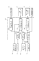
- FIG. 1 is a schematic configuration diagram of an engine to which a vehicle control device according to the present invention is applied. It is a block diagram which shows the internal structure of the engine control unit in the control apparatus of the vehicle which concerns on this invention. It is a flowchart which shows the control routine of valve operation control of the electric wastegate valve which concerns on this invention.
- FIG. 1 is a schematic configuration diagram of an engine 1 to which a vehicle control device is applied.
- a thick solid line in FIG. 1 indicates a power supply wiring 20 that supplies power from the alternator 18 to the battery 21.
- FIG. 2 is a block diagram showing an internal configuration of the engine control unit 30 in the vehicle control apparatus.
- an engine (internal combustion engine) 1 is a multi-cylinder in-cylinder direct injection gasoline engine mounted on a vehicle (not shown), and more specifically, a fuel injection valve (fuel supply means) 7 for each cylinder.
- the fuel can be supplied to the combustion chamber 2 of each cylinder from the fuel injection valve 7 at an arbitrary injection timing and injection amount.
- the engine 1 is provided with a combustion chamber 2.
- the engine 1 is provided with an intake passage 4 including an intake pipe 4 a for introducing air into the combustion chamber 2, an intake manifold 4 b, and an intake port 4 c so as to communicate with the combustion chamber 2.
- the engine 1 is provided with an exhaust passage 5 including an exhaust port 5 a for discharging exhaust gas from the combustion chamber 2, an exhaust manifold 5 b, and an exhaust pipe 5 c so as to communicate with the combustion chamber 2.
- the engine 1 faces the combustion chamber 2 so as to ignite a mixture of fuel and air introduced into the combustion chamber 2, and a fuel injection valve 7 that supplies the fuel into the combustion chamber 2. And are provided.
- a compressor housing 8 a of a turbocharger 8 is provided in communication with the intake passage 4 of the engine 1.
- An intake air passage 4 between the compressor housing 8a of the turbocharger 8 and the combustion chamber 2 of the engine 1 is connected to an intercooler 9 and an electronically controlled throttle valve (intake air amount adjusting means) 10 from the compressor housing 8a side of the turbocharger 8. And are provided.
- An air cleaner 11 is provided in the uppermost stream of the intake passage 4 of the engine 1.
- the intake passage 4 of the engine 1 is provided with a bypass passage 4d including a bypass valve 12 so as to communicate the upstream side of the compressor housing 8a of the turbocharger 8 with the downstream side of the compressor housing 8a.
- a turbine housing 8b of a turbocharger 8 (corresponding to the turbine of the present invention) is provided in communication with the exhaust passage 5 of the engine 1.
- the exhaust passage 5 of the engine 1 is provided with a bypass passage (corresponding to the bypass passage of the present invention) 5d so as to communicate the upstream side of the turbine housing 8b of the turbocharger 8 and the downstream side of the turbine housing 8b. Yes.
- An electric wastegate valve (waistgate valve) 13 is provided in the bypass passage 5d.
- the exhaust passage 5 downstream of the turbine housing 8b of the turbocharger 8 is provided with a three-way catalyst 14 having a function of purifying CO, HC and NOx in the exhaust gas.
- the turbocharger 8 rotates the turbine with the exhaust gas introduced from the turbine housing 8b, and compresses the intake air introduced from the air cleaner 11 by a compressor provided coaxially with the turbine.
- the intercooler 9 cools the intake air that has been compressed and heated by the compressor of the turbocharger 8.
- the electronically controlled throttle valve 10 adjusts the amount of intake air introduced into the combustion chamber 2.
- the electronically controlled throttle valve 10 is provided with a throttle position sensor 10a for detecting the degree of opening of the throttle valve.
- the air cleaner 11 removes dust in the intake air sucked from the uppermost stream.
- the bypass valve 12 adjusts the amount of intake air that bypasses the intake air compressed by the compressor of the turbocharger 8 upstream of the compressor housing 8a via the bypass passage 4d.
- the electric wastegate valve 13 operates a butterfly valve with power from a motor or the like to adjust the flow rate of exhaust gas flowing into the bypass passage 5d, that is, to adjust the flow rate of exhaust gas flowing into the turbine housing 8b of the turbocharger 8. Then, the pressure and flow rate of the intake air compressed by the compressor of the turbocharger 8 are adjusted.
- the electric wastegate valve 13 is provided with a position sensor that detects the degree of opening of the wastegate valve.
- the intake manifold 4b and the exhaust manifold 5b are provided with an exhaust gas recirculation passage 15 for returning a part of the exhaust gas to the intake air so as to communicate with each other, that is, for recirculating the exhaust gas to the intake air.
- the exhaust gas recirculation passage 15 is connected upstream of the intake manifold 4b via an exhaust gas recirculation valve 16 that adjusts the amount of exhaust gas that returns to the intake air, that is, the flow rate of exhaust gas to be recirculated.
- the exhaust gas recirculation passage 15 is provided with an exhaust gas recirculation cooler 17 that cools the exhaust gas introduced into the intake manifold 4b.
- the engine 1 is provided with an alternator (rotating electric machine) 18.
- the alternator 18 is connected to the crankshaft 3 of the engine 1 via the auxiliary belt 19.
- the alternator 18 is electrically connected to a battery (storage battery) 21 that stores electric power via a power supply wiring 20.
- the alternator 18 generates electric power by being driven by the crankshaft 3, and is equipped with electric parts such as a vehicle headlight and a wiper, and electronic control parts such as an electronic control throttle valve 10 and an electric wastegate valve 13 of the engine 1.
- the power is supplied to the battery 21.
- the crankshaft 3 is connected to an axle that rotates the wheels of the vehicle via a transmission, and the alternator 18 can also generate power (regenerative power generation) by the rotational force of the axle of the vehicle.
- the amount of power generated by the alternator 18 is controlled by the engine control unit 30.
- the engine control unit 30 is a control device for performing comprehensive control of the vehicle including operation control of the engine 1, and includes an input / output device, a storage device (ROM, RAM, nonvolatile RAM, etc.), a
- Sensors such as sensors, various devices such as a bypass valve 12, an electric wastegate valve 13, an exhaust gas recirculation valve 16, an alternator 18, a battery 21, and a control mode changeover switch 24 for switching a vehicle control mode are electrically connected. Detection information from these sensors is input to the engine control unit 30.
- the control mode changeover switch 24 emphasizes the vehicle control mode (for example, the operation control of the engine 1 or the transmission shift control (not shown)), the fuel efficiency emphasis control mode that emphasizes the fuel efficiency, and the acceleration performance (movement performance) of the vehicle. Is switched to the travel-oriented control mode.
- the control mode changeover switch 24 of the present invention is not limited to a switch, and any switch can be used as long as the control mode can be changed.
- the engine control unit 30 includes a power generation amount calculation unit (regenerative power generation amount calculation unit) 30a, a required output calculation unit 30b, a fuel cut control unit (second operation control unit) 30c, and an alternator.
- the operation control unit 30d includes a waste gate valve operation control unit (first operation control means) 30e and a throttle valve operation control unit (second operation control means) 30f.
- the power generation amount calculation unit 30 a detects the charge amount of the battery 21 and calculates the power generation amount generated by the alternator 18 based on the charge amount of the battery 21, that is, the required power generation amount required for the alternator 18. To do.
- the required power generation amount is calculated so as to increase as the charge amount of the battery 21 decreases. Then, when the required power generation amount is larger than 0 (zero), the power generation amount calculation unit 30a supplies the required power generation amount to the alternator operation control unit 30d and the wastegate valve operation control unit 30e as a required power generation signal.
- the required power generation amount is 0 (zero)
- the required power generation amount is 0 (zero)
- the supply of the required power generation signal from the power generation amount calculation unit 30a is stopped, but the required power generation amount 0 (zero) as the required power generation signal. ) May be supplied.
- the requested output calculation unit 30b is based on the accelerator opening detected by the accelerator position sensor 22a and the vehicle speed detected by the vehicle speed sensor 23, that is, the output torque generated by the engine 1, that is, the output value requested from the engine 1. The required output value is calculated. Then, when the requested output value is larger than 0 (zero), the requested output calculation unit 30b supplies the requested output value to the wastegate valve operation control unit 30e as a requested output signal. Further, when the request output is 0 (zero), the request output calculation unit 30b means that there is no output request, and stops supplying the request output signal to the wastegate valve operation control unit 30e.
- the request output calculation unit 30b is decelerating and the engine 1 is generating positive output torque (for driving the vehicle). Therefore, the required output value 0 (zero) is calculated.
- the requested output value is 0 (zero)
- the supply of the requested output signal from the requested output calculation unit 30b is stopped, but the requested output value 0 (zero) as the requested output signal. ) May be supplied.
- the fuel cut control unit 30c stops the fuel supply when it is determined that the vehicle is decelerating based on the accelerator opening detected by the accelerator position sensor 22a and the vehicle speed detected by the vehicle speed sensor 23, so-called fuel cut.
- the operation of the fuel injection valve 7 is controlled so that Further, the fuel cut control unit 30c starts fuel cut and supplies a fuel cut signal to the throttle valve operation control unit 30f.
- the alternator operation control unit 30d controls the operation of the alternator 18 based on the required power generation amount so that the power generation amount of the alternator 18 becomes the required power generation amount.
- the wastegate valve operation control unit 30e controls the opening degree of the electric wastegate valve 13 based on the required power generation amount, the required output, and the control mode of the vehicle selected by the control mode changeover switch 24.
- the throttle valve operation control unit 30f controls the operation of the electronic control throttle valve 10 so that the electronic control throttle valve 10 is fully opened.
- the engine control unit 30 determines the amount of charge of the battery 21, the accelerator opening detected by the accelerator position sensor 22a, the vehicle speed detected by the vehicle speed sensor 23, and the vehicle switched by the control mode changeover switch 24. Based on the control mode, when the vehicle is in a decelerating state and the battery 21 needs to be charged, the electric wastegate valve 13 is increased as the power generation amount at the alternator 18 (corresponding to the regenerative power generation amount of the present invention) increases. Valve operation control of the electric wastegate valve 13 that is operated to the open side so as to increase the opening degree is performed.
- the valve operation control of the electric wastegate valve 13 performed by the engine control unit 30 in the engine 1 to which the vehicle control apparatus according to the present invention configured as described above is applied will be described.
- FIG. 3 is a flowchart showing a control routine of valve operation control of the electric wastegate valve according to the present invention.
- step S ⁇ b> 10 it is determined whether or not the fuel consumption priority control mode is set.
- the waste gate valve operation control unit 30e determines whether or not the fuel consumption priority control mode in which the vehicle control mode places importance on fuel consumption is selected by the control mode changeover switch 24. If the determination result is true (Yes) and the control mode changeover switch 24 has selected the fuel efficiency-oriented control mode in which the vehicle control mode emphasizes fuel efficiency, the process proceeds to step S12.
- control mode changeover switch 24 when the control mode changeover switch 24 is false, the fuel-consideration-oriented control mode in which the vehicle control mode places importance on fuel efficiency is not selected, and the travel-oriented control places importance on the acceleration performance (motion performance) of the vehicle. If the mode is selected, the process proceeds to step S22.
- step S12 it is determined whether or not the vehicle is decelerating. Specifically, the wastegate valve operation control unit 30e determines whether or not the request output signal is not supplied from the request output calculation unit 30b and the vehicle is decelerating. If the determination result is true (Yes), the request output signal is not supplied from the request output calculation unit 30b, and the vehicle is decelerating, the process proceeds to step S14. If the request output signal is supplied from the request output calculation unit 30b and the vehicle is not decelerating, the process proceeds to step S22. In this embodiment, as an example, vehicle deceleration is determined based on whether or not a required output signal is supplied from the required output calculation unit 30b to the wastegate valve operation control unit 30e. However, the required output value is 0 ( The vehicle may be decelerated by the wastegate valve operation control unit 30e based on whether the vehicle is at zero), the vehicle speed or the accelerator opening, or both the vehicle speed and the accelerator opening.
- step S14 it is determined whether or not there is a regenerative power generation request.
- the required power generation signal is generated from the power generation amount calculation unit 30a so that the alternator 18 is driven by the kinetic energy of the vehicle during deceleration of the vehicle and the alternator 18 generates power (corresponding to the regenerative power generation of the present invention).
- the waste gate valve operation control unit 30e determines whether or not regenerative power generation control for generating power with kinetic energy that the vehicle has has been performed. If the determination result is true (Yes), the required power generation signal is supplied from the power generation amount calculation unit 30a so that the alternator 18 is driven by the kinetic energy possessed by the vehicle while the vehicle is decelerating and the alternator 18 generates power.
- step S16 If there is a regenerative power generation request, the process proceeds to step S16. If the requested power generation signal is not supplied from the power generation amount calculation unit 30a in false (No), it is determined that there is no regenerative power generation request, and the process proceeds to step S22.
- the presence or absence of a regenerative power generation request is determined based on whether or not a required power generation signal is supplied from the power generation amount calculation unit 30a to the wastegate valve operation control unit 30e. You may make it discriminate
- step S16 the electric wastegate valve 13 is opened. Specifically, the electric wastegate valve 13 is operated to open so that the alternator 18 is driven by the kinetic energy possessed by the vehicle and the required power generation amount calculated by the power generation amount calculation unit 30a can be generated. It is controlled by the wastegate valve operation control unit 30e. The electric wastegate valve 13 is operated so that the opening degree increases as the required power generation amount increases. That is, the electric wastegate valve 13 is operated to the open side according to the required power generation amount, and consumption of kinetic energy due to the pumping loss of the engine 1 is suppressed. Then, the process proceeds to step S18.
- step S18 it is determined whether or not a fuel cut is in progress. Specifically, whether or not the vehicle is decelerated based on the accelerator opening and the vehicle speed by the fuel cut control unit 30c, the operation of the fuel injection valve 7 is stopped, and the fuel supply to the combustion chamber 2 is stopped. Is determined by the throttle valve operation control unit 30f. If the determination result is true (Yes) and the vehicle is determined to be in a decelerating state based on the accelerator opening and the vehicle speed, the process proceeds to step S20. If it is false (No) and the fuel is not cut, this routine is returned. In step S20, the electronic control throttle valve 10 is opened.
- the throttle valve operation control unit 30f controls the electronically controlled throttle valve 10 to operate to the fully open side. Then, this routine is returned.
- the opening degree of the electronically controlled throttle valve 10 does not need to be fully opened as long as the pumping loss of the engine 1 can be suppressed.
- step S22 the electric waste gate valve 13 is operated. Specifically, the operation of the electric wastegate valve 13 is controlled by the wastegate valve operation control unit 30e so that the output torque of the engine 1 becomes the required output value calculated by the required output calculation unit 30b. Then, this routine is returned. Note that the operation control of the electric wastegate valve 13 in this step is different from step S16 in that the opening degree of the electric wastegate valve 13 is adjusted so that the output torque of the engine 1 becomes the required output value. . Therefore, depending on the output torque of the engine 1 and the required output value, the electric wastegate valve 13 operates both in the open side and in the close side.
- the fuel consumption priority control mode in which the fuel consumption is emphasized is selected as the vehicle control mode, and the vehicle is decelerating without the supply of the request output signal from the request output calculation unit 30b.
- the electric gate gate valve 13 is opened by the waste gate valve operation control unit 30e. If the vehicle is decelerated and the fuel is cut based on the accelerator opening and the vehicle speed by the fuel cut control unit 30c, the throttle is controlled in order to suppress the pumping loss of the engine 1 due to the increase in intake negative pressure.
- the electronically controlled throttle valve 10 is operated to the fully open side by the valve operation control unit 30f. Further, if the vehicle control mode is not a fuel efficiency-oriented control mode that places importance on fuel efficiency, a request output signal is supplied from the request output calculation unit 30b, or the vehicle is not decelerating, the output of the engine 1
- the opening degree of the electric wastegate valve 13 is adjusted so that the torque becomes the required output value calculated by the required output calculation unit 30b.
- the exhaust gas discharged from the engine 1 is passed through the bypass passage 5d to the turbine housing of the turbocharger 8. It is possible to reduce the flow rate of the exhaust gas flowing from the engine 1 and reducing the flow rate of the exhaust gas introduced into the turbine housing 8b of the turbocharger 8 and so-called exhaust pressure. Therefore, as the exhaust pressure is reduced, the pumping loss can be reduced, and braking by the rotational resistance of the engine 1, that is, the braking force of the so-called engine brake can be reduced. Therefore, the consumption of kinetic energy possessed by the vehicle by the braking force of the engine brake As the alternator 18 is driven, the kinetic energy of the vehicle is consumed and the vehicle is decelerated, and the alternator 18 can reliably generate power.
- the electric wastegate valve 13 is operated. That is, the electric wastegate valve 13 is operated so that the opening degree of the electric wastegate valve 13 decreases as the required power generation amount decreases. Therefore, when the charge amount of the battery 21 is sufficient, the power generation amount of the alternator 18 is small, and the consumption of kinetic energy possessed by the vehicle by driving the alternator 18 is small, the opening degree of the electric wastegate valve 13 is made small.
- the opening degree of the electric wastegate valve 13 can be increased to reduce the braking force of the engine brake.
- the feeling of deceleration of the vehicle constant regardless of the amount of power generated by the alternator 18. Further, when the deceleration state of the vehicle is detected, the supply of fuel from the fuel injection valve 7 to the combustion chamber 2 is stopped, and the opening degree of the electronic control throttle valve 10 is operated to the fully open side. When the fuel supply from the engine 7 is stopped, that is, at the time of so-called fuel cut, the pumping loss of the engine 1 due to the increase of the suction negative pressure can be reduced by operating the electronically controlled throttle valve 10 to the fully open side. The braking force can be reduced.
- the output torque of the engine 1 is the required output calculation unit 30b.
- the opening degree of the electric waste gate valve 13 is adjusted so that the required output value calculated in step S1 is obtained. Therefore, since the opening degree of the electric wastegate valve 13 is adjusted so that the required output value is obtained even when the vehicle is decelerating, even if the driver operates the accelerator pedal to accelerate the vehicle, for example. Since the output torque of the engine 1 according to the driver's request can be generated, deterioration of drivability can be prevented.
- the embodiment of the present invention is not limited to the embodiment.
- the engine 1 is a multi-cylinder in-cylinder direct injection gasoline engine.
- the present invention is not limited to this, and any engine having an electric wastegate valve 13 and an alternator 18 can be applied. It goes without saying that it is possible.
- a hybrid vehicle including a motor as a power source in addition to the engine 1 may be affected by the pumping loss of the engine 1 during deceleration and can be similarly applied.
- shaft of the said turbine is not restricted to a compressor, For example, a generator and a fan may be mounted
Abstract
燃費重視制御モードで、車両が減速中で、要求発電信号が供給されていれば、要求発電量が多くなるにつれて電動ウェストゲートバルブの開度が大きくなるように電動ウェストゲートバルブを開弁させる(S10-S16)。そして、アクセル開度と車速とに基づいて、車両が減速状態と判別され燃料カットされていれば、電子制御スロットルバルブを全開側に作動させる(S18,S20)。また、燃費重視制御モードでない、或いは要求出力信号の供給がある、或いは車両が減速中でない、のいずれかであれば、エンジンの出力トルクが要求出力値となるように、電動ウェストゲートバルブの開度を調整する(S10-S14,S22)。
Description
本発明は、車両の制御装置に関し、特に内燃機関のウェストゲートバルブの作動制御に関する。
従来、車両の内燃機関には、内燃機関の出力軸によって駆動され、車両の電装品や内燃機関の電気制御部品等に電力を供給する発電機が備えられている。そして、発電機は、車両に搭載される蓄電池にも電力を供給し、蓄電池を充電している。
例えば、車両の走行中に、車両の電装品や内燃機関の電気制御部品等への電力の供給に加え、蓄電池を充電するために発電機にて発電を行うと、内燃機関は車両を走行させるために必要な出力に加え、発電機を駆動するための出力を発生させる必要がある。
例えば、車両の走行中に、車両の電装品や内燃機関の電気制御部品等への電力の供給に加え、蓄電池を充電するために発電機にて発電を行うと、内燃機関は車両を走行させるために必要な出力に加え、発電機を駆動するための出力を発生させる必要がある。
しかしながら、車両を走行させるために必要な出力に加え、発電機を駆動するための出力を発生させることは、内燃機関の燃費の悪化に繋がる。
そこで、特許文献1では、車両の定常走行時や加速時における発電機の発電量に対して、車両の減速時における発電機の発電量を多くなるように発電機を制御、所謂減速回生制御を行って、車両の持っている運動エネルギにて発電機を駆動し、車両の定常走行時や加速時の内燃機関で消費される燃料量を低減している。
そこで、特許文献1では、車両の定常走行時や加速時における発電機の発電量に対して、車両の減速時における発電機の発電量を多くなるように発電機を制御、所謂減速回生制御を行って、車両の持っている運動エネルギにて発電機を駆動し、車両の定常走行時や加速時の内燃機関で消費される燃料量を低減している。
車両の減速時には、内燃機関のポンピングロスや内燃機関の回転抵抗による制動、所謂エンジンブレーキの制動力が、車両の持っている運動エネルギを消費することで車両が減速する。
上記特許文献1の発電制御装置では、車両の定常走行時や加速時における発電機の発電量に対して、車両の減速時における発電機の発電量が多くなるように発電機の減速回生制御を行っている。
上記特許文献1の発電制御装置では、車両の定常走行時や加速時における発電機の発電量に対して、車両の減速時における発電機の発電量が多くなるように発電機の減速回生制御を行っている。
内燃機関には、排ガスをタービンに導入し、タービンと同軸上に設けられるコンプレッサを駆動して、当該コンプレッサにて吸気を過給するターボチャージャを備えるものがある。
このようなターボチャージャを備える内燃機関では、車両の減速時に、ターボチャージャのタービンを迂回するバイパス通路のバイパス弁が閉弁しており、内燃機関の燃焼室から排出される排ガスがターボチャージャのタービンハウジングに導入される。そして、タービンハウジングのタービンノズル部では、排気通路の通路断面積が絞られており、内燃機関から排出される排ガスの圧力、所謂排圧が上昇し、排気抵抗が上昇することで内燃機関のポンピングロスが増大する。
このようなターボチャージャを備える内燃機関では、車両の減速時に、ターボチャージャのタービンを迂回するバイパス通路のバイパス弁が閉弁しており、内燃機関の燃焼室から排出される排ガスがターボチャージャのタービンハウジングに導入される。そして、タービンハウジングのタービンノズル部では、排気通路の通路断面積が絞られており、内燃機関から排出される排ガスの圧力、所謂排圧が上昇し、排気抵抗が上昇することで内燃機関のポンピングロスが増大する。
このようなターボチャージャを備える内燃機関に、特許文献1の発電機の制御を適用すると、エンジンブレーキの制動力と発電機を駆動するための駆動力によって、車両の持っている運動エネルギが消費されることになり、車両の持っている運動エネルギが急激に消費され車両が急減速を起こしドライバビリティの悪化や、車両の持っている運動エネルギが不足し、発電機を十分に駆動することができなくなり発電機の発電量が低下する虞等があり好ましいことではない。
本発明は、この様な問題を解決するためになされたもので、その目的とするところは、車両の減速時に確実に発電することのできる車両の制御装置を提供することにある。
本発明は、この様な問題を解決するためになされたもので、その目的とするところは、車両の減速時に確実に発電することのできる車両の制御装置を提供することにある。
上記の目的を達成するために、請求項1の車両の制御装置は、車両に搭載され、排気通路に配設されたタービンを有する内燃機関と、前記タービンを迂回するバイパス通路に設けられ、前記バイパス通路へ流れる排ガスの流量を調整するウェストゲートバルブと、前記車両に有する車軸の回転力によって回生発電する回転電機と、前記回転電機によって発電された電力を蓄電する蓄電池と、前記車両の走行状態および前記蓄電池の充電量に応じて、前記回転電機による回生発電量を算出する回生発電量算出手段と、前記回生発電量に応じて前記ウェストゲートバルブの作動を制御する第1の作動制御手段とを備える。
また、請求項2の車両の制御装置では、請求項1において、前記第1の作動制御手段は、前記回生発電量に応じて前記ウェストゲートバルブを開側に作動させる。
また、請求項3の車両の制御装置では、請求項1或いは2において、前記回生発電量算出手段は、前記蓄電池の前記充電量が少なくなるにつれ、前記回転電機の前記回生発電量を増加させ、前記第1の作動制御手段は、前記回生発電量が増加するにつれて、前記ウェストゲートバルブの開度を増大させる。
また、請求項3の車両の制御装置では、請求項1或いは2において、前記回生発電量算出手段は、前記蓄電池の前記充電量が少なくなるにつれ、前記回転電機の前記回生発電量を増加させ、前記第1の作動制御手段は、前記回生発電量が増加するにつれて、前記ウェストゲートバルブの開度を増大させる。
また、請求項4の車両の制御装置では、請求項1から3のいずれか1項において、前記車両は、前記内燃機関の吸気通路に配設され、吸入空気量を調整する吸入空気量調整手段と、アクセル開度を検出するアクセル開度検出手段と、前記内燃機関に燃料を供給する燃料供給手段と、前記吸入空気量調整手段と前記燃料供給手段の作動を制御する第2の作動制御手段と、を備え、前記第2の作動制御手段は、前記アクセル開度検出手段によりアクセルオフが検出されると、前記燃料供給手段からの前記燃料の供給を停止するとともに、前記吸入空気量調整手段の開度を開側に作動させ、前記第1の作動制御手段は、前記吸入空気量調整手段の作動に合わせて、前記ウェストゲートバルブを作動させる。
また、請求項5の車両の制御装置では、請求項1から4のいずれか1項において、前記第1の作動制御手段は、前記車両の走行状態が減速中である際に、前記回生発電量算出手段で算出された回生発電量に応じて前記ウェストゲートバルブの作動を制御する。
請求項1の発明によれば、回生発電量に応じてウェストゲートバルブの作動を制御している。
具体的には、回転電機にて回生発電が行われると、ウェストゲートバルブを開側に作動させることで、内燃機関から排出される排ガスをバイパス通路を介してタービンの下流へ流し、タービンに導入する排ガスの流量を減少させ、内燃機関から排出される排ガスの圧力、所謂排圧を低減することが可能となる。
具体的には、回転電機にて回生発電が行われると、ウェストゲートバルブを開側に作動させることで、内燃機関から排出される排ガスをバイパス通路を介してタービンの下流へ流し、タービンに導入する排ガスの流量を減少させ、内燃機関から排出される排ガスの圧力、所謂排圧を低減することが可能となる。
したがって、排圧の低減に伴って、ポンピングロスを低減し、内燃機関の回転抵抗による制動、所謂エンジンブレーキの制動力を低減できるので、エンジンブレーキの制動力による車両の持っている運動エネルギの消費を低減できる。
よって、車両の持っている運動エネルギを回転電機の駆動に用いることができるので、回転電機の駆動により車両の持っている運動エネルギを消費して車両を減速させつつ回転電機による回生発電を確実に行うことができる。
よって、車両の持っている運動エネルギを回転電機の駆動に用いることができるので、回転電機の駆動により車両の持っている運動エネルギを消費して車両を減速させつつ回転電機による回生発電を確実に行うことができる。
また、請求項2の発明によれば、回生発電量に応じてウェストゲートバルブを開側に作動させているので、内燃機関から排出される排ガスをバイパス通路を介してタービンの下流へ流し、タービンに導入する排ガスの流量を減少させ、内燃機関から排出される排ガスの圧力、所謂排圧を低減することが可能となる。
したがって、排圧の低減に伴って、ポンピングロスを低減し、内燃機関の回転抵抗による制動、所謂エンジンブレーキの制動力を低減できるので、エンジンブレーキの制動力による車両の持っている運動エネルギの消費を低減できる。
よって、車両の持っている運動エネルギを回転電機の駆動に用いることができるので、回転電機の駆動により車両の持っている運動エネルギの消費、即ち車両を減速させつつ回転電機による回生発電を確実に行うことができる。
よって、車両の持っている運動エネルギを回転電機の駆動に用いることができるので、回転電機の駆動により車両の持っている運動エネルギの消費、即ち車両を減速させつつ回転電機による回生発電を確実に行うことができる。
また、請求項3の発明によれば、蓄電池の充電量が少なくなるにつれ、回転電機の回生発電量を増加させ、回転電機の回生発電量が増加するにつれて、ウェストゲートバルブの開度を増大させている。
したがって、蓄電池の充電量が十分にあり、回転電機の回生発電量が少なく、回転電機の駆動による車両の持っている運動エネルギの消費が少ない場合には、ウェストゲートバルブの開度を小さくしてエンジンブレーキの制動力を増大させ、また、蓄電池の充電量が不足し、回転電機の回生発電量が多く、回転電機の駆動による車両の持っている運動エネルギの消費が多い場合には、ウェストゲートバルブの開度を大きくして、エンジンブレーキの制動力を減少させることができる。
よって、回転電機の回生発電量の多小によらず、車両の減速感を一定に保つことができる。
したがって、蓄電池の充電量が十分にあり、回転電機の回生発電量が少なく、回転電機の駆動による車両の持っている運動エネルギの消費が少ない場合には、ウェストゲートバルブの開度を小さくしてエンジンブレーキの制動力を増大させ、また、蓄電池の充電量が不足し、回転電機の回生発電量が多く、回転電機の駆動による車両の持っている運動エネルギの消費が多い場合には、ウェストゲートバルブの開度を大きくして、エンジンブレーキの制動力を減少させることができる。
よって、回転電機の回生発電量の多小によらず、車両の減速感を一定に保つことができる。
また、請求項4の発明によれば、アクセル開度検出手段によりアクセルオフが検出されると燃料供給手段からの燃料の供給を停止するとともに、吸入空気量調整手段の開度を開側に作動させ、そして吸入空気量調整手段の作動に合わせて、ウェストゲートバルブを作動させている。
したがって、燃料供給手段からの燃料の供給停止、所謂燃料カットするとともに、吸入空気量調整手段の開度を開側に作動させることで、吸入負圧の増大による内燃機関のポンピングロスを低減することができるので、エンジンブレーキの制動力を減少させることができる。
よって、車両の持っている運動エネルギを回転電機の駆動に用いることができるので、更に回転電機での回生発電量を増加させることができる。
したがって、燃料供給手段からの燃料の供給停止、所謂燃料カットするとともに、吸入空気量調整手段の開度を開側に作動させることで、吸入負圧の増大による内燃機関のポンピングロスを低減することができるので、エンジンブレーキの制動力を減少させることができる。
よって、車両の持っている運動エネルギを回転電機の駆動に用いることができるので、更に回転電機での回生発電量を増加させることができる。
また、請求項5の発明によれば、車両の走行状態が減速中に、回生発電量算出手段で算出された回生発電量に応じてウェストゲートバルブの作動を制御するので、減速中の車軸の回転力を無駄なく回生発電に変換することができる。
以下、本発明の実施の形態を図面に基づき説明する。
図1は、車両の制御装置が適用されたエンジン1の概略構成図である。なお、図1中の太実線は、オルタネータ18からバッテリ21に電力を供給する電力供給配線20を示している。また、図2は、車両の制御装置におけるエンジンコントロールユニット30の内部構成を示すブロック図である。
図1は、車両の制御装置が適用されたエンジン1の概略構成図である。なお、図1中の太実線は、オルタネータ18からバッテリ21に電力を供給する電力供給配線20を示している。また、図2は、車両の制御装置におけるエンジンコントロールユニット30の内部構成を示すブロック図である。
図1に示すように、エンジン(内燃機関)1は、図示しない車両に搭載される多気筒の筒内直接噴射式ガソリンエンジンであり、詳しくは、各気筒の燃料噴射弁(燃料供給手段)7に燃料を供給し、任意の噴射時期及び噴射量で当該燃料噴射弁7から各気筒の燃焼室2内に噴射可能な構成を成している。
図1に示すように、エンジン1には燃焼室2が設けられている。そして、エンジン1には、空気を燃焼室2に導入する吸気管4aと吸気マニホールド4bと吸気ポート4cからなる吸気通路4が燃焼室2と連通するように設けられている。更にエンジン1には、排ガスを燃焼室2から排出する排気ポート5aと排気マニホールド5bと排気管5cとからなる排気通路5が燃焼室2と連通するように設けられている。そして、エンジン1には、燃焼室2に臨むようにして、燃焼室2内に導入された燃料と空気との混合気に点火する点火プラグ6と、燃料を燃焼室2内に供給する燃料噴射弁7とが設けられている。
図1に示すように、エンジン1には燃焼室2が設けられている。そして、エンジン1には、空気を燃焼室2に導入する吸気管4aと吸気マニホールド4bと吸気ポート4cからなる吸気通路4が燃焼室2と連通するように設けられている。更にエンジン1には、排ガスを燃焼室2から排出する排気ポート5aと排気マニホールド5bと排気管5cとからなる排気通路5が燃焼室2と連通するように設けられている。そして、エンジン1には、燃焼室2に臨むようにして、燃焼室2内に導入された燃料と空気との混合気に点火する点火プラグ6と、燃料を燃焼室2内に供給する燃料噴射弁7とが設けられている。
エンジン1の吸気通路4には、ターボチャージャ8のコンプレッサハウジング8aが連通するように備えられている。そして、ターボチャージャ8のコンプレッサハウジング8aとエンジン1の燃焼室2との間の吸気通路4には、ターボチャージャ8のコンプレッサハウジング8a側よりインタクーラ9と電子制御スロットルバルブ(吸入空気量調整手段)10とが設けられている。そして、エンジン1の吸気通路4の最上流には、エアクリーナ11が設けられている。また、エンジン1の吸気通路4には、ターボチャージャ8のコンプレッサハウジング8aの上流側とコンプレッサハウジング8aの下流側とを連通するようにバイパスバルブ12を備えるバイパス通路4dが設けられている。
エンジン1の排気通路5には、ターボチャージャ8(本発明のタービンに相当)のタービンハウジング8bが連通するように備えられている。そして、エンジン1の排気通路5には、ターボチャージャ8のタービンハウジング8bの上流側とタービンハウジング8bの下流側とを連通するようにバイパス通路(本発明のバイパス通路に相当)5dが設けられている。そして、バイパス通路5dには、電動ウェストゲートバルブ(ウェストゲートバルブ)13が設けられている。また、ターボチャージャ8のタービンハウジング8b下流の排気通路5には、排ガス中のCO、HC及びNOxを浄化する機能を有する三元触媒14が備えられている。
ターボチャージャ8は、タービンハウジング8bより導入される排ガスによってタービンを回転させ、当該タービンと同軸に備えられるコンプレッサにてエアクリーナ11より導入された吸入空気を圧縮するものである。
インタクーラ9は、ターボチャージャ8のコンプレッサにて、圧縮され高温となった吸入空気を冷却するものである。
インタクーラ9は、ターボチャージャ8のコンプレッサにて、圧縮され高温となった吸入空気を冷却するものである。
電子制御スロットルバルブ10は、燃焼室2に導入される吸入空気の量を調節するものである。そして、電子制御スロットルバルブ10には、スロットルバルブの開き度合を検出するスロットルポジションセンサ10aが備えられている。
エアクリーナ11は、最上流から吸入された吸入空気中のゴミを取り除くものである。
バイパスバルブ12は、ターボチャージャ8のコンプレッサにて圧縮された吸入空気を、バイパス通路4dを介してコンプレッサハウジング8aの上流に迂回させる吸入空気の量を調整するものである。
エアクリーナ11は、最上流から吸入された吸入空気中のゴミを取り除くものである。
バイパスバルブ12は、ターボチャージャ8のコンプレッサにて圧縮された吸入空気を、バイパス通路4dを介してコンプレッサハウジング8aの上流に迂回させる吸入空気の量を調整するものである。
電動ウェストゲートバルブ13は、モータ等の動力にてバタフライ式のバルブを作動させ、バイパス通路5dに流入する排ガスの流量を調整する、即ちターボチャージャ8のタービンハウジング8bに流入する排ガスの流量を調整し、ターボチャージャ8のコンプレッサにて圧縮される吸入空気の圧力及び流量を調整するものである。そして、電動ウェストゲートバルブ13には、ウェストゲートバルブの開き度合を検出するポジションセンサが備えられている。
吸気マニホールド4bと排気マニホールド5bには、それぞれが連通するように排ガスの一部を吸気へ戻す、即ち排ガスを吸気に再循環させる排気再循環通路15が設けられている。そして、排気再循環通路15は、吸気マニホールド4bの上流に、排ガスが吸気に戻る量、即ち再循環させる排ガスの流量を調整する排気再循環バルブ16を介して接続されている。また、排気再循環通路15には、吸気マニホールド4bに導入する排ガスを冷却する排気再循環クーラ17が設けられている。
エンジン1には、オルタネータ(回転電機)18が備えられている。
エンジン1には、オルタネータ(回転電機)18が備えられている。
オルタネータ18は、エンジン1のクランクシャフト3と補機ベルト19を介して、接続されている。また、オルタネータ18は、電力供給配線20を介して電力を蓄電するバッテリ(蓄電池)21と電気的に接続されている。そして、オルタネータ18は、クランクシャフト3により駆動されることで発電し、車両の前照灯やワイパー等の電装部品や、エンジン1の電子制御スロットルバルブ10や電動ウェストゲートバルブ13等の電子制御部品やバッテリ21に電力を供給するものである。また、クランクシャフト3は変速機を介して車両の車輪を回転させる車軸に接続されており、オルタネータ18は車両の車軸の回転力によっても発電(回生発電)可能である。なお、オルタネータ18での発電量は、エンジンコントロールユニット30にて制御される。
エンジンコントロールユニット30は、エンジン1の運転制御をはじめとして車両の総合的な制御を行うための制御装置であり、入出力装置、記憶装置(ROM、RAM、不揮発性RAM等)、中央処理装置(CPU)等を含んで構成されている。
エンジンコントロールユニット30は、エンジン1の運転制御をはじめとして車両の総合的な制御を行うための制御装置であり、入出力装置、記憶装置(ROM、RAM、不揮発性RAM等)、中央処理装置(CPU)等を含んで構成されている。
エンジンコントロールユニット30の入力側には、アクセルペダル22の操作量であるアクセル開度を検出するアクセルポジションセンサ(アクセル開度検出手段)22a、車両の車速を検出する車速センサ23、図示しないクランク角センサ等のセンサ類や、バイパスバルブ12、電動ウェストゲートバルブ13、排気再循環バルブ16、オルタネータ18、バッテリ21、車両の制御モードを切り換える制御モード切換スイッチ24等の各種装置が、電気的に接続されており、これらセンサ類からの検出情報がエンジンコントロールユニット30に入力される。
なお、制御モード切換スイッチ24は、車両の制御モード(例えばエンジン1の運転制御或いは図示しないトランスミッションの変速制御等)を、燃費を重視する燃費重視制御モードや車両の加速性能(運動性能)を重視する走行重視制御モードに切り換えるものである。本発明の制御モード切換スイッチ24は、スイッチに限定されるものではなく、制御モードが切り換えられるものであればよい。
なお、制御モード切換スイッチ24は、車両の制御モード(例えばエンジン1の運転制御或いは図示しないトランスミッションの変速制御等)を、燃費を重視する燃費重視制御モードや車両の加速性能(運動性能)を重視する走行重視制御モードに切り換えるものである。本発明の制御モード切換スイッチ24は、スイッチに限定されるものではなく、制御モードが切り換えられるものであればよい。
一方、エンジンコントロールユニット30の出力側には、上記点火プラグ6、燃料噴射弁7、電子制御スロットルバルブ10、バイパスバルブ12、電動ウェストゲートバルブ13、排気再循環バルブ16,オルタネータ18等の各種装置が電気的に接続されており、これら各種装置には各種センサ類からの検出情報に基づき演算された点火時期、燃料噴射量、燃料噴射時期、スロットル開度、バイパスバルブ開度、ウェストゲートバルブ開度、排気再循環バルブ開度や、要求発電量等がそれぞれ出力される。
図2に示すように、エンジンコントロールユニット30は、発電量算出部(回生発電量算出手段)30aと、要求出力算出部30bと、燃料カット制御部(第2の作動制御手段)30cと、オルタネータ作動制御部30dと、ウェストゲートバルブ作動制御部(第1の作動制御手段)30eとスロットルバルブ作動制御部(第2の作動制御手段)30fとで構成されている。
図2に示すように、エンジンコントロールユニット30は、発電量算出部(回生発電量算出手段)30aと、要求出力算出部30bと、燃料カット制御部(第2の作動制御手段)30cと、オルタネータ作動制御部30dと、ウェストゲートバルブ作動制御部(第1の作動制御手段)30eとスロットルバルブ作動制御部(第2の作動制御手段)30fとで構成されている。
発電量算出部30aは、バッテリ21の充電量を検出し、当該バッテリ21の充電量に基づいて、オルタネータ18にて発生させる発電量、即ちオルタネータ18に要求する発電量である要求発電量を算出する。要求発電量は、バッテリ21の充電量が少なくなるにつれて多くなるように算出される。そして、発電量算出部30aは、要求発電量が0(ゼロ)より大きい場合には要求発電信号として、要求発電量をオルタネータ作動制御部30dとウェストゲートバルブ作動制御部30eとに供給する。また、要求発電量が0(ゼロ)である場合には、発電要求が無いことを意味し、オルタネータ作動制御部30dとウェストゲートバルブ作動制御部30eとへの要求発電信号の供給を停止する。なお、本実施例では、要求発電量が0(ゼロ)である場合には、発電量算出部30aからの要求発電信号の供給を停止しているが、要求発電信号として要求発電量0(ゼロ)を供給してもよい。
要求出力算出部30bは、アクセルポジションセンサ22aで検出されるアクセル開度と車速センサ23にて検出される車速とに基づいて、エンジン1にて発生させる出力トルク、即ちエンジン1に要求する出力値である要求出力値を算出する。そして、要求出力算出部30bは、要求出力値が0(ゼロ)より大きい場合には要求出力信号として、要求出力値をウェストゲートバルブ作動制御部30eに供給する。また、要求出力算出部30bは、要求出力が0(ゼロ)である場合には、出力要求が無いことを意味し、ウェストゲートバルブ作動制御部30eへの要求出力信号の供給を停止する。要求出力算出部30bは、例えば、アクセル開度が0(ゼロ)で車速が低下している場合には、車両が減速しており、エンジン1にて正の出力トルク(車両を走行させるための出力トルク)を発生させる必要がないので、要求出力値0(ゼロ)を算出する。なお、本実施例では、要求出力値が0(ゼロ)である場合には、要求出力算出部30bからの要求出力信号の供給を停止しているが、要求出力信号として要求出力値0(ゼロ)を供給してもよい。
燃料カット制御部30cは、アクセルポジションセンサ22aで検出されるアクセル開度と車速センサ23にて検出される車速とに基づいて、車両が減速状態であると判別すると燃料供給を停止、所謂燃料カットを行うように燃料噴射弁7の作動を制御する。また、燃料カット制御部30cは、燃料カットを開始すると共に燃料カット信号をスロットルバルブ作動制御部30fに供給する。
オルタネータ作動制御部30dは、要求発電量に基づいて、オルタネータ18の発電量が要求発電量となるようにオルタネータ18の作動を制御する。
オルタネータ作動制御部30dは、要求発電量に基づいて、オルタネータ18の発電量が要求発電量となるようにオルタネータ18の作動を制御する。
ウェストゲートバルブ作動制御部30eは、要求発電量、要求出力及び制御モード切換スイッチ24によって選択される車両の制御モードに基づいて、電動ウェストゲートバルブ13の開度を制御する。
スロットルバルブ作動制御部30fは、燃料カット信号が供給されると、電子制御スロットルバルブ10が全開となるように電子制御スロットルバルブ10の作動を制御する。
スロットルバルブ作動制御部30fは、燃料カット信号が供給されると、電子制御スロットルバルブ10が全開となるように電子制御スロットルバルブ10の作動を制御する。
そして、エンジンコントロールユニット30は、バッテリ21の充電量と、アクセルポジションセンサ22aにて検出されるアクセル開度と、車速センサ23にて検出される車速と、制御モード切換スイッチ24で切り換えられる車両の制御モードとに基づいて、車両が減速状態にあり、バッテリ21の充電が必要であると、オルタネータ18での発電量(本発明の回生発電量に相当)が多くなるにつれて電動ウェストゲートバルブ13の開度が大きくなるように開側に作動させる電動ウェストゲートバルブ13のバルブ作動制御を行う。
以下、このように構成された本発明に係る車両の制御装置が適用されたエンジン1におけるエンジンコントロールユニット30にて実施される電動ウェストゲートバルブ13のバルブ作動制御について説明する。
以下、このように構成された本発明に係る車両の制御装置が適用されたエンジン1におけるエンジンコントロールユニット30にて実施される電動ウェストゲートバルブ13のバルブ作動制御について説明する。
図3は、本発明に係る電動ウェストゲートバルブのバルブ作動制御の制御ルーチンを示すフローチャートである。
図3に示すように、ステップS10では、燃費重視制御モードか、否かを判別する。詳しくは、制御モード切換スイッチ24で車両の制御モードが燃費を重視する燃費重視制御モードが選択されているか、否かをウェストゲートバルブ作動制御部30eにて、判別する。判別結果が真(Yes)で制御モード切換スイッチ24にて、車両の制御モードが燃費を重視する燃費重視制御モードが選択されていれば、ステップS12に進む。また、偽(No)で、制御モード切換スイッチ24にて、車両の制御モードが燃費を重視する燃費重視制御モードが選択されておらず、車両の加速性能(運動性能)を重視する走行重視制御モードが選択されていれば、ステップS22に進む。
図3に示すように、ステップS10では、燃費重視制御モードか、否かを判別する。詳しくは、制御モード切換スイッチ24で車両の制御モードが燃費を重視する燃費重視制御モードが選択されているか、否かをウェストゲートバルブ作動制御部30eにて、判別する。判別結果が真(Yes)で制御モード切換スイッチ24にて、車両の制御モードが燃費を重視する燃費重視制御モードが選択されていれば、ステップS12に進む。また、偽(No)で、制御モード切換スイッチ24にて、車両の制御モードが燃費を重視する燃費重視制御モードが選択されておらず、車両の加速性能(運動性能)を重視する走行重視制御モードが選択されていれば、ステップS22に進む。
ステップS12では、車両が減速中であるか、否かを判別する。詳しくは、要求出力算出部30bから要求出力信号の供給がなく、車両が減速中であるか、否かをウェストゲートバルブ作動制御部30eにて、判別する。判別結果が真(Yes)で要求出力算出部30bから要求出力信号の供給がなく、車両が減速中であれば、ステップS14に進む。また、偽(No)で、要求出力算出部30bから要求出力信号の供給があり、車両が減速中でなければ、ステップS22に進む。なお、本実施例では、一例として要求出力算出部30bからウェストゲートバルブ作動制御部30eへの要求出力信号の供給の有無で車両の減速を判別しているが、その他に要求出力値が0(ゼロ)であるか否か、又は車速或いはアクセル開度のいずれか、又は車速及びアクセル開度の双方よりウェストゲートバルブ作動制御部30eにて車両の減速を判別するようにしても良い。
ステップS14では、回生発電要求があるか、否かを判別する。詳しくは、車両の減速中に車両が持っている運動エネルギにてオルタネータ18を駆動しオルタネータ18にて発電(本発明の回生発電に相当)するように、発電量算出部30aから要求発電信号が供給、即ち車両が持っている運動エネルギにて発電を行う回生発電制御が行われているか、否かをウェストゲートバルブ作動制御部30eにて、判別する。判別結果が真(Yes)で車両の減速中に車両が持っている運動エネルギにてオルタネータ18を駆動しオルタネータ18にて発電するように、発電量算出部30aから要求発電信号が供給されていれば、回生発電要求があるとして、ステップS16に進む。また、偽(No)で、発電量算出部30aから要求発電信号が供給されていなければ、回生発電要求がないとして、ステップS22に進む。なお、本実施例では、一例として発電量算出部30aからウェストゲートバルブ作動制御部30eへの要求発電信号の供給の有無で回生発電要求の有無を判別しているが、その他に要求発電量が0(ゼロ)であるか否かで回生発電要求の有無を判別するようにしても良い。
ステップS16では、電動ウェストゲートバルブ13を開弁させる。詳しくは、車両の持っている運動エネルギでオルタネータ18を駆動して、発電量算出部30aにて算出された要求発電量を発電できるように、電動ウェストゲートバルブ13が開側に作動するようにウェストゲートバルブ作動制御部30eにて制御する。なお、電動ウェストゲートバルブ13は、要求発電量が多くなるにつれ、開度が大きくなるように作動される。即ち、要求発電量に応じて電動ウェストゲートバルブ13を開側へ作動させ、エンジン1のポンピングロスによる運動エネルギの消費を抑制する。そして、ステップS18に進む。
ステップS18では、燃料カット中か、否かを判別する。詳しくは、燃料カット制御部30cにてアクセル開度と車速とに基づいて、車両が減速状態と判別され燃料噴射弁7の作動が停止され、燃焼室2への燃料供給が停止されたか、否かをスロットルバルブ作動制御部30fにて判別する。判別結果が真(Yes)でアクセル開度と車速とに基づいて、車両が減速状態と判別され燃料カットされていれば、ステップS20に進む。また、偽(No)で、燃料カットがされていなければ、本ルーチンをリターンする。
ステップS20では、電子制御スロットルバルブ10を開弁させる。詳しくは、吸気負圧の増大によるエンジン1のポンピングロスを抑制するため、電子制御スロットルバルブ10が全開側に作動するようにスロットルバルブ作動制御部30fにて制御する。そして、本ルーチンをリターンする。なお、電子制御スロットルバルブ10を開度は、エンジン1のポンピングロスを抑制できれば、全開とする必要はない。
ステップS20では、電子制御スロットルバルブ10を開弁させる。詳しくは、吸気負圧の増大によるエンジン1のポンピングロスを抑制するため、電子制御スロットルバルブ10が全開側に作動するようにスロットルバルブ作動制御部30fにて制御する。そして、本ルーチンをリターンする。なお、電子制御スロットルバルブ10を開度は、エンジン1のポンピングロスを抑制できれば、全開とする必要はない。
また、ステップS22では、電動ウェストゲートバルブ13を作動させる。詳しくは、エンジン1の出力トルクが要求出力算出部30bにて算出された要求出力値となるように、電動ウェストゲートバルブ13の作動をウェストゲートバルブ作動制御部30eにて制御する。そして、本ルーチンをリターンする。なお、本ステップの電動ウェストゲートバルブ13の作動制御は、ステップS16とは異なり、エンジン1の出力トルクが要求出力値となるように電動ウェストゲートバルブ13の開度を調整することを目的としている。よって、エンジン1の出力トルクと要求出力値によっては、電動ウェストゲートバルブ13は、開側へも閉側へも作動することになる。
このように、本発明に係る車両の制御装置では、車両の制御モードが燃費を重視する燃費重視制御モードが選択されて、要求出力算出部30bから要求出力信号の供給がなく車両が減速中であり、車両の減速中に車両が持っている運動エネルギにてオルタネータ18を駆動しオルタネータ18にて発電(回生発電)するように、ウェストゲートバルブ作動制御部30eに発電量算出部30aから要求発電信号が供給されていれば、車両の持っている運動エネルギでオルタネータ18を駆動し、そして発電量算出部30aにて算出された要求発電量が多くなるにつれて電動ウェストゲートバルブ13の開度が大きくなるようにウェストゲートバルブ作動制御部30eにて電動ウェストゲートバルブ13を開弁させる。そして、燃料カット制御部30cにてアクセル開度と車速とに基づいて、車両が減速状態と判別され燃料カットされていれば、吸気負圧の増大によるエンジン1のポンピングロスを抑制するため、スロットルバルブ作動制御部30fにて電子制御スロットルバルブ10を全開側に作動させる。また、車両の制御モードが燃費を重視する燃費重視制御モードでない、或いは要求出力算出部30bから要求出力信号の供給がある、或いは車両が減速中でない、のいずれかであれば、エンジン1の出力トルクが要求出力算出部30bにて算出された要求出力値となるように、電動ウェストゲートバルブ13の開度を調整している。
したがって、要求出力値によらずに、要求発電量に応じて電動ウェストゲートバルブ13を開側に作動させることで、エンジン1から排出される排ガスをバイパス通路5dを介してターボチャージャ8のタービンハウジング8bの下流へ流し、ターボチャージャ8のタービンハウジング8bに導入する排ガスの流量を減少させ、エンジン1から排出される排ガスの圧力、所謂排圧を低減することが可能となる。
よって、排圧の低減に伴って、ポンピングロスを低減し、エンジン1の回転抵抗による制動、所謂エンジンブレーキの制動力を低減できるので、エンジンブレーキの制動力による車両の持っている運動エネルギの消費を低減でき、オルタネータ18の駆動により車両の持っている運動エネルギを消費して車両を減速させつつ、オルタネータ18による発電を確実に行うことができる。
よって、排圧の低減に伴って、ポンピングロスを低減し、エンジン1の回転抵抗による制動、所謂エンジンブレーキの制動力を低減できるので、エンジンブレーキの制動力による車両の持っている運動エネルギの消費を低減でき、オルタネータ18の駆動により車両の持っている運動エネルギを消費して車両を減速させつつ、オルタネータ18による発電を確実に行うことができる。
また、バッテリ21の充電量が少なくなるにつれ、要求発電量を増加させてオルタネータ18での発電量を増加させ、更に要求発電量の増加に伴って、電動ウェストゲートバルブ13の開度が大きくなるように電動ウェストゲートバルブ13を作動させている。即ち、要求発電量が少なくなるに伴って、電動ウェストゲートバルブ13の開度が小さくなるように電動ウェストゲートバルブ13を作動させている。
したがって、バッテリ21の充電量が十分にあり、オルタネータ18の発電量が少なく、オルタネータ18の駆動による車両の持っている運動エネルギの消費が少ない場合には、電動ウェストゲートバルブ13の開度を小さくしてエンジンブレーキの制動力を増大させ、また、バッテリ21の充電量が不足し、オルタネータ18の発電量が多く、オルタネータ18の駆動による車両の持っている運動エネルギの消費が多い場合には、電動ウェストゲートバルブ13の開度を大きくして、エンジンブレーキの制動力を減少させることができる。
したがって、バッテリ21の充電量が十分にあり、オルタネータ18の発電量が少なく、オルタネータ18の駆動による車両の持っている運動エネルギの消費が少ない場合には、電動ウェストゲートバルブ13の開度を小さくしてエンジンブレーキの制動力を増大させ、また、バッテリ21の充電量が不足し、オルタネータ18の発電量が多く、オルタネータ18の駆動による車両の持っている運動エネルギの消費が多い場合には、電動ウェストゲートバルブ13の開度を大きくして、エンジンブレーキの制動力を減少させることができる。
よって、オルタネータ18の発電量の多小によらず、車両の減速感を一定に保つことができる。
また、車両の減速状態が検出されると燃料噴射弁7から燃焼室2への燃料の供給を停止し、更に電子制御スロットルバルブ10の開度を全開側に作動させているので、燃料噴射弁7からの燃料の供給停止時、所謂燃料カット時に、電子制御スロットルバルブ10を全開側に作動させることで、吸入負圧の増大によるエンジン1のポンピングロスを低減することができるので、エンジンブレーキの制動力を減少させることができる。
また、車両の減速状態が検出されると燃料噴射弁7から燃焼室2への燃料の供給を停止し、更に電子制御スロットルバルブ10の開度を全開側に作動させているので、燃料噴射弁7からの燃料の供給停止時、所謂燃料カット時に、電子制御スロットルバルブ10を全開側に作動させることで、吸入負圧の増大によるエンジン1のポンピングロスを低減することができるので、エンジンブレーキの制動力を減少させることができる。
したがって、車両の持っている運動エネルギをオルタネータ18の駆動に用いることができるので、更にオルタネータ18での発電量を増加させることができる。
また、車両の制御モードが燃費を重視する燃費重視制御モードでない、即ち車両の加速性能(運動性能)を重視する走行重視制御モードである場合には、エンジン1の出力トルクが要求出力算出部30bにて算出された要求出力値となるように、電動ウェストゲートバルブ13の開度を調整している。
したがって、車両が減速中であっても要求出力値となるように、電動ウェストゲートバルブ13の開度を調整しているので、例えば車両を加速させるために運転者がアクセルペダルを操作しても、運転者の要求に応じたエンジン1の出力トルクを発生させることができるので、運転性の悪化を防止することができる。
また、車両の制御モードが燃費を重視する燃費重視制御モードでない、即ち車両の加速性能(運動性能)を重視する走行重視制御モードである場合には、エンジン1の出力トルクが要求出力算出部30bにて算出された要求出力値となるように、電動ウェストゲートバルブ13の開度を調整している。
したがって、車両が減速中であっても要求出力値となるように、電動ウェストゲートバルブ13の開度を調整しているので、例えば車両を加速させるために運転者がアクセルペダルを操作しても、運転者の要求に応じたエンジン1の出力トルクを発生させることができるので、運転性の悪化を防止することができる。
以上で発明の実施形態の説明を終えるが、本発明の形態は実施形態に限定されるものではない。
例えば、本実施形態は、エンジン1を多気筒の筒内直接噴射式ガソリンエンジンとしているが、もちろんこれに限定されるものではなく、電動ウェストゲートバルブ13とオルタネータ18とを備えるエンジンであれば適用可能であることは言うまでもない。
また、エンジン1の他に動力源としてモータを備えるハイブリッド車においても減速時にエンジン1のポンピングロスの影響を受けることがあり、同様に適応できる。
さらに、前記タービンの同軸上に配置されるものはコンプレッサに限らず、例えば発電機やファンが装着されても良い。
例えば、本実施形態は、エンジン1を多気筒の筒内直接噴射式ガソリンエンジンとしているが、もちろんこれに限定されるものではなく、電動ウェストゲートバルブ13とオルタネータ18とを備えるエンジンであれば適用可能であることは言うまでもない。
また、エンジン1の他に動力源としてモータを備えるハイブリッド車においても減速時にエンジン1のポンピングロスの影響を受けることがあり、同様に適応できる。
さらに、前記タービンの同軸上に配置されるものはコンプレッサに限らず、例えば発電機やファンが装着されても良い。
1 エンジン(内燃機関)
4 吸気通路
5 排気通路
5d バイパス通路
7 燃料噴射弁(燃料供給手段)
8 ターボチャージャ(タービン)
10 電子制御スロットルバルブ(吸入空気量調整手段)
13 電動ウェストゲートバルブ(ウェストゲートバルブ)
18 オルタネータ(回転電機)
21 バッテリ(蓄電池)
22a アクセルポジションセンサ(アクセル開度検出手段)
30 エンジンコントロールユニット
30a 発電量算出部(回生発電量算出手段)
30b 要求出力算出部
30c 燃料カット制御部(第2の作動制御手段)
30d オルタネータ作動制御部
30e ウェストゲートバルブ作動制御部(第1の作動制御手段)
30f スロットルバルブ作動制御部(第2の作動制御手段)
Claims (5)
- 車両に搭載され、排気通路に配設されたタービンを有する内燃機関と、
前記タービンを迂回するバイパス通路に設けられ、前記バイパス通路へ流れる排ガスの流量を調整するウェストゲートバルブと、
前記車両に有する車軸の回転力によって回生発電する回転電機と、
前記回転電機によって発電された電力を蓄電する蓄電池と、
前記車両の走行状態および前記蓄電池の充電量に応じて、前記回転電機による回生発電量を算出する回生発電量算出手段と、
前記回生発電量に応じて前記ウェストゲートバルブの作動を制御する第1の作動制御手段と、を備える車両の制御装置。 - 前記第1の作動制御手段は、前記回生発電量に応じて前記ウェストゲートバルブを開側に作動させる、請求項1に記載の車両の制御装置。
- 前記回生発電量算出手段は、前記蓄電池の前記充電量が少なくなるにつれ、前記回転電機の前記回生発電量を増加させ、
前記第1の作動制御手段は、前記回生発電量が増加するにつれて、前記ウェストゲートバルブの開度を増大させる、請求項1或いは2に記載の車両の制御装置。 - 前記車両は、
前記内燃機関の吸気通路に配設され、吸入空気量を調整する吸入空気量調整手段と、
アクセル開度を検出するアクセル開度検出手段と、
前記内燃機関に燃料を供給する燃料供給手段と、
前記吸入空気量調整手段と前記燃料供給手段の作動を制御する第2の作動制御手段と、を備え、
前記第2の作動制御手段は、前記アクセル開度検出手段によりアクセルオフが検出されると、前記燃料供給手段からの前記燃料の供給を停止するとともに、前記吸入空気量調整手段の開度を開側に作動させ、
前記第1の作動制御手段は、前記吸入空気量調整手段の作動に合わせて、前記ウェストゲートバルブを作動させる、請求項1から3のいずれか1項に記載の車両の制御装置。 - 前記第1の作動制御手段は、前記車両の走行状態が減速中である際に、前記回生発電量算出手段で算出された回生発電量に応じて前記ウェストゲートバルブの作動を制御する、請求項1から4のいずれか1項に記載の車両の制御装置。
Priority Applications (3)
| Application Number | Priority Date | Filing Date | Title |
|---|---|---|---|
| CN201380074037.2A CN105026721B (zh) | 2013-03-01 | 2013-12-24 | 用于车辆的控制器 |
| US14/769,742 US9598073B2 (en) | 2013-03-01 | 2013-12-24 | Controller for vehicle |
| EP13876557.3A EP2963262B1 (en) | 2013-03-01 | 2013-12-24 | Controller for vehicle |
Applications Claiming Priority (2)
| Application Number | Priority Date | Filing Date | Title |
|---|---|---|---|
| JP2013-040929 | 2013-03-01 | ||
| JP2013040929A JP6156622B2 (ja) | 2013-03-01 | 2013-03-01 | 車両の制御装置 |
Publications (1)
| Publication Number | Publication Date |
|---|---|
| WO2014132539A1 true WO2014132539A1 (ja) | 2014-09-04 |
Family
ID=51427824
Family Applications (1)
| Application Number | Title | Priority Date | Filing Date |
|---|---|---|---|
| PCT/JP2013/084483 WO2014132539A1 (ja) | 2013-03-01 | 2013-12-24 | 車両の制御装置 |
Country Status (5)
| Country | Link |
|---|---|
| US (1) | US9598073B2 (ja) |
| EP (1) | EP2963262B1 (ja) |
| JP (1) | JP6156622B2 (ja) |
| CN (1) | CN105026721B (ja) |
| WO (1) | WO2014132539A1 (ja) |
Cited By (1)
| Publication number | Priority date | Publication date | Assignee | Title |
|---|---|---|---|---|
| JP2020152306A (ja) * | 2019-03-22 | 2020-09-24 | トヨタ自動車株式会社 | ハイブリッド車両、及びハイブリッド車両の制動方法 |
Families Citing this family (7)
| Publication number | Priority date | Publication date | Assignee | Title |
|---|---|---|---|---|
| DE102015014810B4 (de) * | 2015-11-14 | 2022-08-11 | Audi Ag | Verfahren zum Betreiben einer Antriebseinrichtung für ein Kraftfahrzeug sowie entsprechende Antriebseinrichtung |
| JP6672785B2 (ja) | 2015-12-25 | 2020-03-25 | 三菱自動車工業株式会社 | エンジンの制御装置 |
| JP2017166405A (ja) * | 2016-03-16 | 2017-09-21 | トヨタ自動車株式会社 | 内燃機関の発電システム |
| KR20180126169A (ko) * | 2017-05-17 | 2018-11-27 | 현대자동차주식회사 | 엔진 시스템 |
| JP6897512B2 (ja) * | 2017-11-13 | 2021-06-30 | トヨタ自動車株式会社 | ハイブリッド車両の駆動力制御装置 |
| CN108045371A (zh) * | 2017-12-14 | 2018-05-18 | 阜阳裕晟电子科技有限公司 | 一种车辆控制系统 |
| JP2022149908A (ja) * | 2021-03-25 | 2022-10-07 | 本田技研工業株式会社 | 車両制御装置 |
Citations (5)
| Publication number | Priority date | Publication date | Assignee | Title |
|---|---|---|---|---|
| JP2004092455A (ja) * | 2002-08-30 | 2004-03-25 | Mitsubishi Motors Corp | ハイブリッド車の出力制御装置 |
| JP2005009314A (ja) * | 2003-06-16 | 2005-01-13 | Nissan Diesel Motor Co Ltd | エンジンの過給装置 |
| JP2006090150A (ja) * | 2004-09-21 | 2006-04-06 | Toyota Motor Corp | バッテリ充電状態と触媒温度に応じて過給度を制御されるハイブリッド車 |
| JP2011080398A (ja) * | 2009-10-06 | 2011-04-21 | Mitsubishi Electric Corp | 電動過給機の制御装置 |
| JP2011144716A (ja) | 2010-01-12 | 2011-07-28 | Mitsubishi Motors Corp | 発電制御装置 |
Family Cites Families (7)
| Publication number | Priority date | Publication date | Assignee | Title |
|---|---|---|---|---|
| JP2738819B2 (ja) | 1994-08-22 | 1998-04-08 | 本田技研工業株式会社 | ハイブリッド車両の発電制御装置 |
| JP3177153B2 (ja) | 1996-04-10 | 2001-06-18 | 本田技研工業株式会社 | ハイブリッド車両の制御装置 |
| JP3096446B2 (ja) | 1997-09-17 | 2000-10-10 | 本田技研工業株式会社 | ハイブリッド車両の制御装置 |
| JP3835152B2 (ja) * | 2000-10-05 | 2006-10-18 | 日産自動車株式会社 | 過給機の制御装置 |
| JP2006220045A (ja) * | 2005-02-09 | 2006-08-24 | Toyota Motor Corp | 車両の減速時制御方法 |
| JP4941534B2 (ja) * | 2009-10-15 | 2012-05-30 | 株式会社デンソー | 内燃機関のウエストゲートバルブ制御装置 |
| US8630759B2 (en) * | 2009-11-20 | 2014-01-14 | GM Global Technology Operations LLC | Control of regenerative braking in a hybrid vehicle |
-
2013
- 2013-03-01 JP JP2013040929A patent/JP6156622B2/ja active Active
- 2013-12-24 CN CN201380074037.2A patent/CN105026721B/zh active Active
- 2013-12-24 EP EP13876557.3A patent/EP2963262B1/en active Active
- 2013-12-24 US US14/769,742 patent/US9598073B2/en active Active
- 2013-12-24 WO PCT/JP2013/084483 patent/WO2014132539A1/ja active Application Filing
Patent Citations (5)
| Publication number | Priority date | Publication date | Assignee | Title |
|---|---|---|---|---|
| JP2004092455A (ja) * | 2002-08-30 | 2004-03-25 | Mitsubishi Motors Corp | ハイブリッド車の出力制御装置 |
| JP2005009314A (ja) * | 2003-06-16 | 2005-01-13 | Nissan Diesel Motor Co Ltd | エンジンの過給装置 |
| JP2006090150A (ja) * | 2004-09-21 | 2006-04-06 | Toyota Motor Corp | バッテリ充電状態と触媒温度に応じて過給度を制御されるハイブリッド車 |
| JP2011080398A (ja) * | 2009-10-06 | 2011-04-21 | Mitsubishi Electric Corp | 電動過給機の制御装置 |
| JP2011144716A (ja) | 2010-01-12 | 2011-07-28 | Mitsubishi Motors Corp | 発電制御装置 |
Cited By (3)
| Publication number | Priority date | Publication date | Assignee | Title |
|---|---|---|---|---|
| JP2020152306A (ja) * | 2019-03-22 | 2020-09-24 | トヨタ自動車株式会社 | ハイブリッド車両、及びハイブリッド車両の制動方法 |
| CN111720223A (zh) * | 2019-03-22 | 2020-09-29 | 丰田自动车株式会社 | 混合动力车辆和制动混合动力车辆的方法 |
| JP7143799B2 (ja) | 2019-03-22 | 2022-09-29 | トヨタ自動車株式会社 | ハイブリッド車両、及びハイブリッド車両の制動方法 |
Also Published As
| Publication number | Publication date |
|---|---|
| JP6156622B2 (ja) | 2017-07-05 |
| CN105026721B (zh) | 2017-11-28 |
| EP2963262B1 (en) | 2019-02-06 |
| CN105026721A (zh) | 2015-11-04 |
| JP2014169646A (ja) | 2014-09-18 |
| US20160251011A1 (en) | 2016-09-01 |
| US9598073B2 (en) | 2017-03-21 |
| EP2963262A1 (en) | 2016-01-06 |
| EP2963262A4 (en) | 2016-08-10 |
Similar Documents
| Publication | Publication Date | Title |
|---|---|---|
| JP6156622B2 (ja) | 車両の制御装置 | |
| JP3721088B2 (ja) | ハイブリッド車両の制御装置 | |
| JP4380674B2 (ja) | 過給圧制御装置 | |
| JP6672785B2 (ja) | エンジンの制御装置 | |
| JP4434174B2 (ja) | 過給機付き内燃機関の制御装置 | |
| JP5899104B2 (ja) | 車両の制御装置 | |
| JP5109994B2 (ja) | 過給機付き内燃機関の制御装置 | |
| JP2007092757A (ja) | 車両用エンジンの排ガス再循環装置 | |
| JP2006220045A (ja) | 車両の減速時制御方法 | |
| JP5208083B2 (ja) | 電動過給機の制御装置 | |
| JP2009149195A (ja) | ハイブリッドシステムの制御装置 | |
| JP2011001844A (ja) | 内燃機関の制御装置 | |
| JP2017140970A (ja) | ハイブリッド車両及びその制御方法 | |
| JP4123707B2 (ja) | エンジンの制御装置 | |
| JP2006105026A (ja) | 内燃機関用過給制御装置 | |
| JP5998528B2 (ja) | ハイブリッド車両 | |
| JP2010116896A (ja) | 内燃機関の制御装置 | |
| JP2003269180A (ja) | 過給圧制御装置 | |
| JP2005351184A (ja) | インタークーラパイパス制御手段を備えたハイブリッド車 | |
| JP5565378B2 (ja) | 内燃機関の制御システム | |
| JP2013245595A (ja) | ハイブリッド車両の制御装置 | |
| WO2022244132A1 (ja) | ハイブリッド車両の制御方法及びハイブリッド車両の制御装置 | |
| JP5334695B2 (ja) | 電動過給機の制御装置 | |
| JP2007077955A (ja) | 車両用パワートレイン制御装置 | |
| JP6561828B2 (ja) | エンジンの制御装置 |
Legal Events
| Date | Code | Title | Description |
|---|---|---|---|
| WWE | Wipo information: entry into national phase |
Ref document number: 201380074037.2 Country of ref document: CN |
|
| 121 | Ep: the epo has been informed by wipo that ep was designated in this application |
Ref document number: 13876557 Country of ref document: EP Kind code of ref document: A1 |
|
| WWE | Wipo information: entry into national phase |
Ref document number: 14769742 Country of ref document: US |
|
| WWE | Wipo information: entry into national phase |
Ref document number: 2013876557 Country of ref document: EP |
|
| NENP | Non-entry into the national phase |
Ref country code: DE |