WO2014129145A1 - 多気筒エンジンの冷却装置 - Google Patents
多気筒エンジンの冷却装置 Download PDFInfo
- Publication number
- WO2014129145A1 WO2014129145A1 PCT/JP2014/000719 JP2014000719W WO2014129145A1 WO 2014129145 A1 WO2014129145 A1 WO 2014129145A1 JP 2014000719 W JP2014000719 W JP 2014000719W WO 2014129145 A1 WO2014129145 A1 WO 2014129145A1
- Authority
- WO
- WIPO (PCT)
- Prior art keywords
- cylinder
- water jacket
- path
- coolant
- engine
- Prior art date
- Legal status (The legal status is an assumption and is not a legal conclusion. Google has not performed a legal analysis and makes no representation as to the accuracy of the status listed.)
- Ceased
Links
Images





Classifications
-
- F—MECHANICAL ENGINEERING; LIGHTING; HEATING; WEAPONS; BLASTING
- F01—MACHINES OR ENGINES IN GENERAL; ENGINE PLANTS IN GENERAL; STEAM ENGINES
- F01P—COOLING OF MACHINES OR ENGINES IN GENERAL; COOLING OF INTERNAL-COMBUSTION ENGINES
- F01P3/00—Liquid cooling
- F01P3/02—Arrangements for cooling cylinders or cylinder heads
-
- F—MECHANICAL ENGINEERING; LIGHTING; HEATING; WEAPONS; BLASTING
- F02—COMBUSTION ENGINES; HOT-GAS OR COMBUSTION-PRODUCT ENGINE PLANTS
- F02F—CYLINDERS, PISTONS OR CASINGS, FOR COMBUSTION ENGINES; ARRANGEMENTS OF SEALINGS IN COMBUSTION ENGINES
- F02F1/00—Cylinders; Cylinder heads
- F02F1/02—Cylinders; Cylinder heads having cooling means
- F02F1/10—Cylinders; Cylinder heads having cooling means for liquid cooling
- F02F1/14—Cylinders with means for directing, guiding or distributing liquid stream
-
- F—MECHANICAL ENGINEERING; LIGHTING; HEATING; WEAPONS; BLASTING
- F01—MACHINES OR ENGINES IN GENERAL; ENGINE PLANTS IN GENERAL; STEAM ENGINES
- F01P—COOLING OF MACHINES OR ENGINES IN GENERAL; COOLING OF INTERNAL-COMBUSTION ENGINES
- F01P3/00—Liquid cooling
- F01P3/20—Cooling circuits not specific to a single part of engine or machine
-
- F—MECHANICAL ENGINEERING; LIGHTING; HEATING; WEAPONS; BLASTING
- F01—MACHINES OR ENGINES IN GENERAL; ENGINE PLANTS IN GENERAL; STEAM ENGINES
- F01P—COOLING OF MACHINES OR ENGINES IN GENERAL; COOLING OF INTERNAL-COMBUSTION ENGINES
- F01P5/00—Pumping cooling-air or liquid coolants
- F01P5/10—Pumping liquid coolant; Arrangements of coolant pumps
-
- F—MECHANICAL ENGINEERING; LIGHTING; HEATING; WEAPONS; BLASTING
- F02—COMBUSTION ENGINES; HOT-GAS OR COMBUSTION-PRODUCT ENGINE PLANTS
- F02F—CYLINDERS, PISTONS OR CASINGS, FOR COMBUSTION ENGINES; ARRANGEMENTS OF SEALINGS IN COMBUSTION ENGINES
- F02F1/00—Cylinders; Cylinder heads
- F02F1/24—Cylinder heads
- F02F1/26—Cylinder heads having cooling means
- F02F1/36—Cylinder heads having cooling means for liquid cooling
- F02F1/40—Cylinder heads having cooling means for liquid cooling cylinder heads with means for directing, guiding, or distributing liquid stream
-
- F—MECHANICAL ENGINEERING; LIGHTING; HEATING; WEAPONS; BLASTING
- F01—MACHINES OR ENGINES IN GENERAL; ENGINE PLANTS IN GENERAL; STEAM ENGINES
- F01P—COOLING OF MACHINES OR ENGINES IN GENERAL; COOLING OF INTERNAL-COMBUSTION ENGINES
- F01P3/00—Liquid cooling
- F01P3/02—Arrangements for cooling cylinders or cylinder heads
- F01P2003/021—Cooling cylinders
-
- F—MECHANICAL ENGINEERING; LIGHTING; HEATING; WEAPONS; BLASTING
- F01—MACHINES OR ENGINES IN GENERAL; ENGINE PLANTS IN GENERAL; STEAM ENGINES
- F01P—COOLING OF MACHINES OR ENGINES IN GENERAL; COOLING OF INTERNAL-COMBUSTION ENGINES
- F01P3/00—Liquid cooling
- F01P3/02—Arrangements for cooling cylinders or cylinder heads
- F01P2003/024—Cooling cylinder heads
-
- F—MECHANICAL ENGINEERING; LIGHTING; HEATING; WEAPONS; BLASTING
- F01—MACHINES OR ENGINES IN GENERAL; ENGINE PLANTS IN GENERAL; STEAM ENGINES
- F01P—COOLING OF MACHINES OR ENGINES IN GENERAL; COOLING OF INTERNAL-COMBUSTION ENGINES
- F01P3/00—Liquid cooling
- F01P3/02—Arrangements for cooling cylinders or cylinder heads
- F01P2003/027—Cooling cylinders and cylinder heads in parallel
-
- F—MECHANICAL ENGINEERING; LIGHTING; HEATING; WEAPONS; BLASTING
- F01—MACHINES OR ENGINES IN GENERAL; ENGINE PLANTS IN GENERAL; STEAM ENGINES
- F01P—COOLING OF MACHINES OR ENGINES IN GENERAL; COOLING OF INTERNAL-COMBUSTION ENGINES
- F01P3/00—Liquid cooling
- F01P3/02—Arrangements for cooling cylinders or cylinder heads
- F01P2003/028—Cooling cylinders and cylinder heads in series
-
- F—MECHANICAL ENGINEERING; LIGHTING; HEATING; WEAPONS; BLASTING
- F01—MACHINES OR ENGINES IN GENERAL; ENGINE PLANTS IN GENERAL; STEAM ENGINES
- F01P—COOLING OF MACHINES OR ENGINES IN GENERAL; COOLING OF INTERNAL-COMBUSTION ENGINES
- F01P2060/00—Cooling circuits using auxiliaries
-
- F—MECHANICAL ENGINEERING; LIGHTING; HEATING; WEAPONS; BLASTING
- F01—MACHINES OR ENGINES IN GENERAL; ENGINE PLANTS IN GENERAL; STEAM ENGINES
- F01P—COOLING OF MACHINES OR ENGINES IN GENERAL; COOLING OF INTERNAL-COMBUSTION ENGINES
- F01P2060/00—Cooling circuits using auxiliaries
- F01P2060/16—Outlet manifold
-
- F—MECHANICAL ENGINEERING; LIGHTING; HEATING; WEAPONS; BLASTING
- F02—COMBUSTION ENGINES; HOT-GAS OR COMBUSTION-PRODUCT ENGINE PLANTS
- F02F—CYLINDERS, PISTONS OR CASINGS, FOR COMBUSTION ENGINES; ARRANGEMENTS OF SEALINGS IN COMBUSTION ENGINES
- F02F1/00—Cylinders; Cylinder heads
- F02F1/02—Cylinders; Cylinder heads having cooling means
- F02F1/10—Cylinders; Cylinder heads having cooling means for liquid cooling
Definitions
- the present invention relates to a cooling device for a multi-cylinder engine such as an automobile, and particularly belongs to a technical field of an engine for cooling a cylinder head and a cylinder block with a coolant.
- Patent Document 1 discloses that when the engine is cold, the flow of coolant to the cylinder block is cut off, while a small amount of coolant is flowed from one end side to the other end side of the cylinder row to the cylinder head. Disclosed is a technology for achieving early warm-up by causing the coolant to flow from one end side of the cylinder row to the other end side of the cylinder row as the temperature rises and increasing the flow rate of the coolant to be circulated to the cylinder head. ing.
- the exhaust gas causes the temperature on the cylinder head side of the cylinder block to be higher than that on the opposite side, and the temperature on the exhaust side of the cylinder block is higher than that on the intake side.
- the temperature difference tends to occur between the exhaust side and the exhaust side.
- the coolant flows from one end side to the other end side of the cylinder row of the cylinder block, the temperature of the coolant rises as it flows from the upstream side to the downstream side of the flow path.
- a spacer is arranged in the water jacket of the cylinder block, and the cooling liquid is divided into an upper flow path and a lower flow path to increase the flow rate and flow rate of the cooling liquid in the upper flow path of the water jacket. Then, after flowing from one end side of the cylinder row to the other end side, a technique for suppressing a temperature difference in the vertical direction of the cylinder by flowing in a U-turn shape so as to return to the one end side is disclosed.
- this conventional technique has a problem that the temperature distribution of the entire cylinder becomes non-uniform because the temperature difference between the exhaust side and the intake side of each cylinder and the temperature difference between the cylinders cannot be sufficiently suppressed.
- JP 2010-163920 A Japanese Patent No. 4845620
- the present invention suppresses the temperature difference in the vertical direction of each cylinder in the cylinder block constituting the multi-cylinder engine, the temperature difference between the exhaust side and the intake side of each cylinder, and the temperature difference between each cylinder, thereby An object is to obtain a uniform temperature distribution.
- a cooling device for a multi-cylinder engine is configured as follows.
- the invention includes a water jacket provided in a cylinder block so as to surround cylinder bores of a plurality of cylinders arranged in series, and a water jacket provided in a cylinder head.
- a cooling device for a multi-cylinder engine provided with a coolant passage for circulating coolant through a water jacket and a radiator, wherein the cylinder block is provided on one end side of a cylinder row, and the water block of the cylinder block
- An introduction portion for introducing a coolant into the jacket, and a throttle portion that is provided in the vicinity of the introduction portion and restricts the coolant introduced from the introduction portion from flowing to the intake side portion of the water jacket of the cylinder block;
- the water jacket of the cylinder block is provided at the center of the cylinder row on the intake side.
- the exhaust side portion of the water jacket of the cylinder block is formed so that the flow path cross-sectional area is larger on the upper side in the cylinder axial direction than on the lower side. It is characterized by that.
- a spacer is disposed in the water jacket of the cylinder block with a space between the inner wall portion and the outer wall portion, and the throttle portion is disposed on the outer periphery of the spacer.
- the exhaust side portion of the spacer may be formed such that the space between the spacer and the outer wall portion is wider on the upper side in the cylinder axial direction than on the lower side.
- the water jacket of the cylinder block is configured as a groove formed in an annular shape on the upper surface of the cylinder block.
- the outer side wall is the outer wall portion
- the inner side wall is the inner wall surface. The inner wall.
- the cylinder head has a discharge portion that is provided on the other end side of the cylinder row and discharges the coolant from the water jacket of the cylinder head, and the water jacket of the cylinder block and the cylinder
- the water jacket of the head is connected to each other via a communication path, the coolant path bypasses the radiator, and connects the discharge part and the introduction part provided in the cylinder head; and the radiator And a second path connecting the discharge part and the introduction part provided in the cylinder head via a first control valve that controls the flow rate of the coolant, and the flow rate of the coolant is bypassed the radiator.
- a cooling circuit control unit that sequentially opens the first to third control valves as the engine temperature rises.
- the second path may pass through at least one of an air conditioning heater core or an EGR cooler.
- the third path may pass through at least one of an engine oil cooler or an oil heat exchanger of an automatic transmission.
- the upper side (cylinder head side) in the cylinder axial direction of the exhaust side portion of the water jacket of the cylinder block is formed so that the flow passage cross-sectional area is larger than the lower side. It is possible to further cool the upper part of the exhaust side of the cylinder block, the temperature of which is particularly likely to rise due to the exhaust gas, from the lower part of the exhaust side. Therefore, the temperature difference in the vertical direction of each cylinder is suppressed.
- the throttle portion provided in the vicinity of the introduction portion restricts the coolant introduced from the introduction portion from flowing to the intake side portion of the water jacket of the cylinder block, more cooling water is supplied to the exhaust side portion.
- the exhaust side cylinder block whose temperature tends to rise more than the intake side can be further cooled, and the temperature difference between the intake side and the exhaust side of each cylinder is suppressed.
- an introduction part for introducing the coolant into the water jacket of the cylinder block is provided on one end side of the cylinder row, and the throttle restricts the coolant introduced from the introduction part from flowing to the intake side part of the water jacket of the cylinder block.
- a discharge portion for discharging the coolant from the water jacket of the cylinder block is provided in the center portion of the cylinder row on the intake side, so that the coolant introduced from one end side of the cylinder row Flows from the exhaust side to the intake side via the other end side of the cylinder row, and is discharged from the center of the cylinder row on the intake side.
- the cylinder on one end side of the cylinder row is cooled on the exhaust side by the relatively low temperature coolant, whereas on the intake side
- the cooling liquid hardly flows and is not cooled by the throttle portion
- the cylinder on the other end side of the cylinder row is cooled on the exhaust side and the intake side by the relatively high temperature cooling liquid. Therefore, if the exhaust side and intake side cooling of each cylinder is averaged and compared, the cylinder on one end and the cylinder on the other end of the cylinder row are cooled approximately equally, so the temperature difference between each cylinder is suppressed. Will be.
- the temperature difference in the vertical direction of each cylinder, the temperature difference between the exhaust side and the intake side of each cylinder, and the temperature difference between each cylinder are suppressed, and the temperature distribution of the entire cylinder is made uniform. Can be.
- the spacer is provided in the water jacket of the cylinder block with a space between the inner wall portion and the outer wall portion, the spacer is introduced from the introduction portion. It is possible to prevent the cylinder from being directly cooled by the coolant and locally becoming low temperature.
- the exhaust side portion of the spacer is formed so that the distance between the spacer and the outer wall portion is wider on the upper side in the cylinder axial direction than on the lower side. The effect of reducing the temperature difference in the vertical direction can be realized.
- the throttle part is provided on the outer periphery of the spacer, the throttle part can be easily formed integrally with the spacer.
- the cylinder head is provided on the other end side of the cylinder row and has a discharge portion for discharging the coolant from the water jacket of the cylinder head.
- the water jacket of the cylinder block and the cylinder head is Since they are connected to each other via a communication path, when the first to third control valves are closed by the cooling circuit control unit during the warm-up operation, the cooling is performed only on the first path connecting the head side discharge unit and the introduction unit. Although the liquid circulates, the cooling liquid hardly flows to the water jacket of the cylinder block at this time, so that the temperature of the cylinder block gradually increases. Therefore, warm-up of the engine can be promoted.
- the first to third control valves are sequentially opened as the engine temperature rises by the cooling circuit control unit.
- the coolant circulates also in the second path.
- the second path does not pass through the radiator and the cylinder block, warming up of the engine is continuously promoted.
- the second control valve is opened, the coolant also circulates in the third path. Since this third path is connected to the cylinder block, the cylinder block is also cooled to some extent, but bypasses the radiator. As a result, the engine warms up.
- the coolant circulates also in the fourth path, and since this fourth path is connected to the radiator, the temperature of the coolant is lowered by this radiator, and the engine after the warm-up is performed. Can be maintained at a predetermined temperature. Therefore, each cylinder and cylinder head can be appropriately cooled according to the engine temperature.
- the first control valve is opened during the warm-up, and the coolant is circulated through the second path passing through the air conditioning heater core or the EGR cooler. Heating performance can be ensured, and the EGR cooler can be properly cooled.
- the third control valve is opened during warm-up, and the coolant is circulated through the third path passing through the engine oil cooler or the oil heat exchanger of the automatic transmission. Therefore, the engine oil can be cooled, the transmission oil is appropriately heated, and the sliding resistance is reduced early due to the early decrease in the viscosity, thereby improving the fuel efficiency.
- FIG. 1 shows a schematic configuration of a cooling device 1 for a multi-cylinder engine according to an embodiment of the present invention.
- the multi-cylinder engine 2 (hereinafter simply referred to as “engine”) has a so-called cross flow in which four cylinders are arranged in series in the crankshaft direction, and an intake system and an exhaust system are arranged on opposite sides of the cylinder head 4.
- This is an in-line four-cylinder diesel engine of the type.
- the engine 2 is located in an engine room (not shown) provided at the front of the vehicle, the cylinder row faces in the vehicle width direction, the exhaust system is located on the rear side in the vehicle front-rear direction, and the cylinder shaft of each cylinder is It is mounted so that it faces up and down.
- the engine 2 mainly includes a cylinder block 3 and a cylinder head 4 provided on the upper side of the cylinder block 3.
- the cylinder block 3 is provided with a block-side water jacket 33, an introduction hole 36, and a block-side discharge hole 37, which will be described later, and the cylinder head 4 is provided with a head-side water jacket 61 and a head-side discharge hole 62, which will be described later. Yes.
- the cooling water W introduced into the block side water jacket 33 from the introduction hole 36 is discharged from the block side discharge hole 37, and the cooling water W introduced from the introduction hole 36 into the head side water jacket 61 is discharged from the head side. It is discharged from the hole 62.
- the introduction hole 36 is provided with a water pump 5 for supplying cooling water W into the water jackets 33 and 61.
- the water pump 5 is a pump that is passively driven by the rotation of the engine 2.
- the cooling device 1 is provided with a coolant path for circulating the coolant W through the water jackets 33 and 61 via the radiator 7 and the like as appropriate.
- the coolant paths are the first to fourth paths 11 to 14.
- the path switching for circulating the cooling water W to any one of the first to fourth paths 11 to 14 is performed by the cooling circuit control unit 101 by the thermostat valve 6a and the first to third control valves 6b to 6d. This is done by controlling the cooling circuit switching unit 6 configured as described above. Next, the first to fourth paths 11 to 14 will be described in detail.
- the first path 11 connects the head side discharge hole 62 and the introduction hole 36. While this 1st path
- the thermostat valve 6a is a valve that opens when the control valves 6b to 6d fail and the water temperature of the cooling water W exceeds a predetermined value. According to the thermostat valve 6a, the cooling water is only supplied to the first path 11 when it is normal. When W circulates and an abnormality occurs, the cooling water W also circulates in the second path 12 described later, and the engine 2 can be protected.
- the water temperature sensor 102 is provided in the vicinity of the head side discharge hole 62.
- the second path 12 connects the head side discharge hole 62 and the introduction hole 36.
- the second path 12 bypasses the radiator 7 and passes through the idling stop water pump 21, the air conditioning heater core 22, the EGR cooler 23 and the EGR valve 24, and the first control valve 6b in this order.
- the idling stop water pump 21 is a pump for flowing the cooling water W to the air conditioning heater core 22 when the engine 2 is temporarily stopped during idling. Further, the EGR cooler 23 and the EGR valve 24 pass through the second path 12 so as to be parallel to each other.
- the third path 13 connects the discharge hole 37 and the introduction hole 36.
- the third path 13 bypasses the radiator 7 and passes through the engine oil cooler 25, the oil heat exchanger 26 of the automatic transmission, and the second control valve 6c in this order.
- the engine oil cooler 25 is provided in the block side discharge hole 37.
- the fourth path 14 connects the head side discharge hole 62 and the introduction hole 36.
- the fourth path 14 passes through the water temperature sensor 102, the radiator 7, and the third control valve 6d in this order.
- the cooling circuit control unit 101 is one of control units provided in the ECU 100.
- the cooling circuit control unit 101 detects the temperature of the cooling water W, the engine speed sensor 103, the fuel injection amount sensor 104, and the load state of the engine 2 determined by the engine speed and the fuel injection amount. Based on the predicted head combustion chamber wall surface temperature T of the engine 2, the first to third control valves 6b to 6d are controlled according to the predicted head combustion chamber wall surface temperature T.
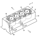
- the cylinder block 3 is mainly composed of a cylinder block body 30 and a spacer 40.
- the gasket 50 is not a configuration of the cylinder block 3, but is illustrated in FIG. 2 for convenience of explanation.
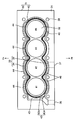
- the cylinder block main body 30 is provided with cylinder bores 32 of the first to fourth cylinders # 1 to # 4 arranged in series so that the cylinder shafts face in the vertical direction.
- the upper surface 31 of the cylinder block main body 30 is provided with a block-side water jacket 33 which is an annular concave groove surrounding the four cylinder bores 32.
- the block-side water jacket 33 includes an exhaust-side passage 34 that passes through the exhaust side of the cylinder block 3 and an intake-side passage 35 that passes through the intake side of the cylinder block 3.
- the first cylinder # 1 to the fourth cylinder # 4 are arranged in order from the left to the right when the cylinder block 3 is viewed from the intake side, and the cylinder row in which these cylinders # 1 to # 4 are arranged.
- the side with the first cylinder # 1 is referred to as “one end side”, and the side with the fourth cylinder is referred to as “other end side”.
- the inner side walls are the inner wall portions 34a and 35a, and the outer side walls are the outer wall portions, respectively. 34b and 35b.
- the cylinder block body 30 is provided at one end side of the cylinder row, and is provided at the introduction hole 36 for introducing the cooling water W to the block side water jacket 33 and at the central portion of the cylinder row on the intake side, and the block side water jacket.
- a discharge hole 37 for discharging the cooling water W from 33 is provided.
- the cylinder block body 30 is provided with screw holes 38... 38 into which a plurality of head bolts for connecting the cylinder block 3 and the cylinder head 4 to each other via the gasket 50 can be screwed.
- the gasket 50 is a metal sheet gasket in which a plurality of metal plates are overlapped and a plurality of places are integrated by caulking, and the overall shape thereof is a shape corresponding to the upper surface 31 of the cylinder block body 30.
- the gasket 50 has circular holes 51... 51 at positions corresponding to the cylinder bores 32 of the cylinder block body 30 and head bolt insertion holes 54 at positions corresponding to the screw holes 38. 54 is provided.
- the gasket 50 is provided with a plurality of first communication holes 52 ... 52 and second communication holes 53 ... 53 that allow the block-side water jacket 33 and the head-side water jacket 61 to communicate with each other.
- the first communication holes 52 ... 52 are provided on one end side of the cylinder row of the gasket 50, and the second communication holes 53 ... 53 are provided on the exhaust side and the intake side, respectively.
- the elastic repulsive force of the gasket 50 seals the circumference of the circular holes 51... 51 and the circumference of the insertion holes 54. This prevents leakage of combustion gas from the combustion chamber, leakage of the cooling water W from the water jackets 33 and 61, and the like.
- the cylinder head 4 is provided with a head side discharge hole 62 for discharging the cooling water W from the head side water jacket 61 on the other end side of the cylinder row.
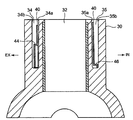
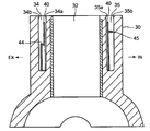
- FIGS. 4 and 5 are vertical sectional views of the cylinder block 3 in the second cylinder # 2 and the fourth cylinder # 4, respectively.
- the spacer 40 disposed inside the block-side water jacket 33 is placed so that the bottom thereof is in contact with the bottom surface of the block-side water jacket 33, and the block-side water jacket is arranged.
- the inner wall portions 34a and 35a of 33 and the outer wall portions 34b and 35b are spaced from each other.
- the gap between the inner circumferential surface of the spacer 40 and the inner wall portions 34a and 35a of the block-side water jacket 33 is relatively narrow, and the gap between the outer circumferential surface of the spacer 40 and the outer wall portions 34b and 35b is relatively smaller.
- the gap on the outside of the spacer 40 is a main flow path through which the cooling water W flows. It should be noted that the “exhaust-side flow path 34” or “intake-side flow path 35” simply refers to a gap outside the spacer 40.
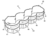
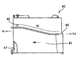
- FIGS. 7 and 8 are perspective views of the spacer 40 alone viewed from the intake side and the exhaust side
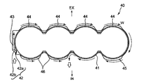
- FIG. 9 is a plan view viewed from above
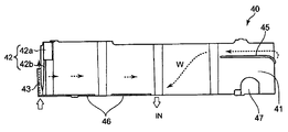
- FIGS. 10 and 11 are viewed from the exhaust side and the intake side
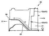
- FIG. 12 and FIG. 13 are side views seen from the introduction part side and the opposite side.
- symbols of IN (intake side) and EX (exhaust side) indicating directions when the spacer 40 is disposed inside the block-side water jacket 33 are attached.
- the spacer 40 has a thickness that allows it to be stored in the block-side water jacket 33 with a space therebetween, and a height that does not protrude from the upper surface 31 of the cylinder block 3, and extends substantially parallel to the cylinder axial direction. It is mainly comprised by the cyclic
- the vertical wall portion 41 on one end side and the intake side is provided with a rib-like throttle portion 42 that protrudes outward from the outer periphery thereof.
- the aperture portion 42 includes an upper aperture portion 42a and a lower aperture portion 42b, and the upper aperture portion 42a is formed such that the amount of protrusion is larger than that of the lower aperture portion 42b.
- the vertical wall portion 41 on one end side is smoothly inclined so as to climb from the lower end of the vertical wall portion 41 to the center in the cylinder axial direction from the intake side to the exhaust side.
- a rib-shaped inclined portion 43 is provided.
- a stepped portion 44 connected to the upper end of the inclined portion 43 is formed at the center of the vertical wall portion 41 on the exhaust side in the cylinder axial direction. According to this, when the spacer 40 is disposed inside the block-side water jacket 33, the space between the spacer 40 and the outer wall portion 34b is wider on the upper side of the stepped portion 44 than on the lower side.
- the vertical wall portion 41 is provided so as to wrap around from the exhaust side to the intake side on the other end side, and is connected to the above-described step portion 44, and from the exhaust side.
- a rib-shaped guide portion 45 that is smoothly inclined so as to further climb to the cylinder head side toward the intake side may be provided.
- a flange portion 46 protruding outward from the outer periphery thereof may be formed at the lower end of the vertical wall portion 41 on the intake side.
- a cold district heater insertion portion 47 which is a notch for inserting a cold district heater, may be provided at the lower end of the vertical wall portion 41 on the other end side. .
- the resin Since the spacer 40 is disposed inside the block-side water jacket 33, the resin has heat resistance that can withstand the high temperature in the cylinder block 3 and rigidity that does not cause deformation or breakage due to the water pressure of the cooling water W. It is formed with.
- a resin such as a polyamide-based thermoplastic resin (PA66, PPA, etc.), an olefin-based thermoplastic resin (PP), a polyphenylene sulfide-based thermoplastic resin (PPS), or the like can be selected in combination. Yes, glass fiber or the like may be blended with the aforementioned resin as necessary.
- the resin spacer 40 is integrally molded by an injection molding machine.
- FIGS. In these drawings, an arrow indicating the flow of the cooling water W when the spacer 40 is disposed inside the block-side water jacket 33 is attached.
- the cooling water W is introduced into the block-side water jacket 33 from the introduction hole 36 of the cylinder block 3 by the water pump 5.
- the spacer 40 is disposed in the block-side water jacket 33 with a space between the inner wall portions 34a and 35a and between the outer wall portions 34b and 35b. Therefore, it is possible to prevent the cooling water W introduced from the introduction hole 36 from directly hitting the inner wall portion 35a of the block-side water jacket 33 and locally reducing the temperature of the cylinder at that portion.
- the cooling water W introduced from the introduction hole 36 is restricted from flowing to the intake side flow path 35 by the throttle portion 42 provided on the intake side near the introduction hole 36. Most of the air flows into the exhaust side flow path 34.
- the lower throttle part 42b has a smaller projection amount than the upper throttle part 42a, a relatively small amount of the cooling water W passing through the wider gap between the lower throttle part 42b and the outer wall part 35b is taken into the intake side flow path. It flows to 35.
- the cooling water W that has flowed into the exhaust-side flow path 34 is supplied to the cylinder by the inclined portion 43 provided on the exhaust side in the vicinity of the introduction hole 36. It is directed toward the head 4 and flows.
- the cooling circuit control unit 101 performs engine cold If control is performed so that the cooling water W circulates only in the first path 11 sometimes, the cooling water W directed to the cylinder head 4 side does not flow into the exhaust-side flow path 34 of the block-side water jacket 33, but the first It flows into the head side water jacket 61 through the communication hole 52.
- the cylinder block 3 is not cooled and the temperature gradually rises and warming up of the engine 2 is promoted.
- the cooling water W that has flowed from the inclined portion 43 to the exhaust-side flow path 34 is separated by the stepped portion 44 that is connected to the upper end portion of the inclined portion 43.
- the outer wall portion 34b are wide and flow more toward the upper side of the stepped portion 44 having a larger flow path cross-sectional area than the lower side.
- the cooling water W that has flowed through the exhaust side flow path 34 is connected to the stepped portion 44, and is guided from the exhaust side flow path 34 by the guide portion 45 provided on the other end side of the vertical wall portion 41. As it flows toward the intake side flow path 35, it is directed to the cylinder head side.
- the cooling water W directed to the cylinder head side tends to flow to the head-side water jacket 61 through the second communication hole 53 provided on the intake side of the gasket 50, so that the cylinder head 4 is cooled more actively. can do.
- the cooling water W that has not flowed into the head-side water jacket 61 through the second communication hole 53 passes through the intake-side flow path 35 and is provided at the center of the cylinder row on the intake side of the cylinder block 3.
- the block side discharge hole 37 is discharged.
- the first cylinder # 1 has a relatively low temperature cooling water. While the exhaust side is cooled by W, on the intake side, the cooling water W hardly flows and is not cooled by the throttle portion 42. However, the fourth cylinder # 4 is not cooled by the relatively high temperature of the cooling water W. The intake side is cooled.
- the temperature distribution of the entire cylinder can be made uniform by suppressing the temperature difference in the vertical direction of each cylinder, the temperature difference between the exhaust side and the intake side of each cylinder, and the temperature difference between each cylinder.
- the cooling water W that has flowed into the intake-side flow path 35 through the gap between the lower throttle portion 42b and the outer wall portion 35b has a flange portion 46 that protrudes outward from the outer periphery of the spacer 40. Since the flange portion 46 is provided at the lower end of the intake side portion 41, it is possible to prevent the flange portion 46 from entering the spacer 40 from the lower end of the spacer 40 and to prevent the temperature difference in the vertical direction of the cylinder from increasing.
- the block side water jacket 33 is inserted by inserting the cold region heater into the cold region heater insertion portion 47 of the vertical wall portion 41. Freezing of the cooling water W inside can be prevented.
- FIG. 14 is a flowchart showing a control method of the cooling circuit control unit 101
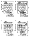
- FIG. 15 is a block diagram showing a cooling method according to the engine temperature. A method of controlling the cooling device 1 by the cooling circuit control unit 101 will be described below with reference to FIG. 15 according to the flowchart of FIG.
- step S1 when the engine is cold, all the control valves 6b to 6d are closed (step S1). At this time, the cooling water W is circulated through the first path 11 as shown in FIG. Note that a relatively small amount of cooling water W flows through the cylinder head 4 at this time in order to warm up the engine 2 while preventing local heating.
- step S2 it is determined whether the head combustion chamber wall surface temperature T is equal to or higher than a predetermined temperature T1 (for example, 150 ° C.) (step S2).
- a predetermined temperature T1 for example, 150 ° C.
- step S2 If it is determined in step S2 that the head combustion chamber wall surface temperature T is equal to or higher than the predetermined temperature T1, the first control valve 6b is opened (step S3). At this time, the cooling water W is circulated through the first path 11 and the second path 12 as shown in FIG.
- step S4 it is determined whether the head combustion chamber wall surface temperature T is equal to or higher than a predetermined temperature T2 (T2> T1) (step S4).
- step S4 If it is determined in step S4 that the head combustion chamber wall surface temperature T is equal to or higher than the predetermined temperature T2, the second control valve 6c is opened (step S5). At this time, the cooling water W is circulated from the first path to the third paths 11 to 13 as shown in FIG.
- step S6 it is determined whether the engine 2 has been warmed up. This determination may be made based on whether the head combustion chamber wall surface temperature T is equal to or higher than a predetermined temperature T3 (T3> T2).
- step S6 when it is determined in step S6 that the warm-up of the engine 2 has been completed, the third control valve 6d is opened (step S7). At this time, as shown in FIG. 15D, the cooling water W is circulated from the first path to all of the fourth paths 11 to 14.
- the cooling water W is supplied only to the first path 11 connecting the head side discharge hole 62 and the introduction hole 36.
- the cooling water W hardly flows into the block-side water jacket 33 at this time, the temperature of the cylinder block 3 gradually increases. Therefore, warm-up of the engine 2 can be promoted.
- first to third control valves 6b to 6d are sequentially opened by the cooling circuit control unit 101 as the engine temperature rises.
- the cooling water W circulates also in the second path 12, but the second path 12 does not pass through the radiator 7, and the cooling water W enters the block-side water jacket 33. Almost does not flow, so the warm-up of the engine 2 continues to be promoted.
- the cooling water W also circulates in the third path 13, and since the third path 13 is connected to the cylinder block 3, the cylinder block 3 is also cooled to some extent. Since the radiator 7 is bypassed, the engine 2 is warmed up.
- the cooling water W circulates also in the fourth path 14, and since the fourth path 14 is connected to the radiator 7, the temperature of the cooling water W is adjusted by the radiator 7.
- the engine 2 after being warmed down can be kept at a predetermined temperature.
- the first to third control valves 6b to 6d are closed, and the first to third control valves 6b to 6d are sequentially turned on as the engine temperature rises.
- opening the valve each cylinder and the cylinder head 4 can be appropriately cooled according to the temperature of the engine 2.
- the heating performance is improved during the warm-up. Can be secured, and the EGR cooler 23 can be appropriately cooled.
- the third control valve 6d is opened during warm-up and the cooling water W is circulated through the third path 13 passing through the engine oil cooler 25 or the oil heat exchanger 26 of the automatic transmission,
- the oil can be cooled and the transmission oil can be appropriately heated to reduce the sliding resistance at an early stage due to the early decrease in viscosity, thereby improving the fuel efficiency.
- the throttle part 42, the inclined part 43, and the step part 44 are formed integrally with the spacer 40, but without providing the spacer 40, the internal shape of the block-side water jacket 33 is devised to have these functions. These may be formed by the cylinder block 3 itself.
- the present invention is applied to an in-line four-cylinder diesel engine.
- any number of cylinders may be used as long as there are a plurality of cylinders.
- the present invention is not limited to a diesel engine. May be.
- the entire cylinder can be uniformly cooled in a multi-cylinder engine such as an automobile, it is suitably used in the manufacturing industry of this type of engine.
Landscapes
- Engineering & Computer Science (AREA)
- Chemical & Material Sciences (AREA)
- Combustion & Propulsion (AREA)
- Mechanical Engineering (AREA)
- General Engineering & Computer Science (AREA)
- Cylinder Crankcases Of Internal Combustion Engines (AREA)
Abstract
Description
2 多気筒エンジン
3 シリンダブロック
4 シリンダヘッド
5 ウォータポンプ
6b 第1制御弁
6c 第2制御弁
6d 第3制御弁
7 ラジエータ
11 第1経路
12 第2経路
13 第3経路
14 第4経路
22 空調用ヒータコア
23 EGRクーラ
25 エンジンオイルクーラ
26 自動変速機のオイル熱交換器
30 シリンダブロック本体(シリンダブロック)
32 シリンダボア
33 ブロック側ウォータジャケット(シリンダブロックのウォータジャケット)
34 排気側流路(ウォータジャケットの排気側部分)
35 吸気側流路(ウォータジャケットの吸気側部分)
34a、35a 内壁部
34b、35b 外壁部
36 導入孔(導入部)
37 ブロック側排出孔(シリンダブロックの排出部)
40 スペーサ
42 絞り部
42a 上側絞り部
42b 下側絞り部
52 第1連通孔(連通路)
61 ヘッド側ウォータジャケット(シリンダヘッドのウォータジャケット)
62 ヘッド側排出孔(シリンダヘッドの排出部)
101 冷却回路制御部
W 冷却水(冷却液)
#1~#4 気筒
Claims (5)
- 直列に配置された複数の気筒のシリンダボアを囲むようにシリンダブロックに設けられたウォータジャケットと、シリンダヘッドに設けられたウォータジャケットとを有し、ウォータポンプにより、これらウォータジャケットとラジエータとを経由させて冷却液を循環させる冷却液経路が備えられた多気筒エンジンの冷却装置であって、
前記シリンダブロックは、
気筒列の一端側に設けられて、前記シリンダブロックのウォータジャケットへ冷却液を導入する導入部と、
前記導入部の近傍に設けられ、前記導入部から導入された冷却液が前記シリンダブロックのウォータジャケットの吸気側部分へ流れるのを制限する絞り部と、
吸気側における気筒列の中央部に設けられ、前記シリンダブロックのウォータジャケットから冷却液を排出する排出部と
を有し、
前記シリンダブロックのウォータジャケットの排気側部分は、シリンダ軸方向の上側の方が下側よりも流路断面積が大きくなるように形成されている
ことを特徴とする多気筒エンジンの冷却装置。 - 前記シリンダブロックのウォータジャケット内に、その内壁部との間及び外壁部との間に間隔を設けてスペーサが配設され、
前記絞り部は、前記スペーサの外周に形成され、
前記スペーサの排気側部分は、シリンダ軸方向の上側の方が下側よりも前記スペーサと前記外壁部の間隔が広くなるように形成されている
ことを特徴とする請求項1に記載の多気筒エンジンの冷却装置。 - 前記シリンダヘッドは、
気筒列の他端側に設けられ、前記シリンダヘッドのウォータジャケットから冷却液を排出する排出部を有し、
前記シリンダブロックのウォータジャケットと前記シリンダヘッドのウォータジャケットは互いに連通路を介して接続され、
前記冷却液経路は、
前記ラジエータを迂回し、前記シリンダヘッドに設けられた排出部と前記導入部とを連結する第1経路と、
前記ラジエータを迂回し、冷却液の流量を制御する第1制御弁を介して前記シリンダヘッドに設けられた排出部と前記導入部とを連結する第2経路と、
前記ラジエータを迂回し、冷却液の流量を制御する第2制御弁を介して前記シリンダブロックに設けられた排出部と前記導入部とを連結する第3経路と、
冷却液の流量を制御する第3制御弁と前記ラジエータを介して前記シリンダヘッドに設けられた排出部と前記導入部とを連結する第4経路と
を有し、
暖機運転時は前記第1乃至第3制御弁を閉弁し、エンジン温度の上昇に伴って前記第1乃至第3制御弁を順次開弁する冷却回路制御部を備える
ことを特徴とする請求項1または2に記載の多気筒エンジンの冷却装置。 - 前記第2経路は、空調用ヒータコアまたはEGRクーラの少なくとも一方を経由している
ことを特徴とする請求項3に記載の多気筒エンジンの冷却装置。 - 前記第3経路は、エンジンオイルクーラまたは自動変速機のオイル熱交換器の少なくとも一方を経由している
ことを特徴とする請求項3に記載の多気筒エンジンの冷却装置。
Priority Applications (3)
| Application Number | Priority Date | Filing Date | Title |
|---|---|---|---|
| US14/769,169 US9777615B2 (en) | 2013-02-21 | 2014-02-12 | Cooling device for multiple cylinder engine |
| CN201480002477.1A CN104641092B (zh) | 2013-02-21 | 2014-02-12 | 多汽缸发动机的冷却装置 |
| DE112014000931.8T DE112014000931B4 (de) | 2013-02-21 | 2014-02-12 | Kühlvorrichtung für Mehrzylindermotor |
Applications Claiming Priority (2)
| Application Number | Priority Date | Filing Date | Title |
|---|---|---|---|
| JP2013031898A JP5880471B2 (ja) | 2013-02-21 | 2013-02-21 | 多気筒エンジンの冷却装置 |
| JP2013-031898 | 2013-02-21 |
Publications (1)
| Publication Number | Publication Date |
|---|---|
| WO2014129145A1 true WO2014129145A1 (ja) | 2014-08-28 |
Family
ID=51390945
Family Applications (1)
| Application Number | Title | Priority Date | Filing Date |
|---|---|---|---|
| PCT/JP2014/000719 Ceased WO2014129145A1 (ja) | 2013-02-21 | 2014-02-12 | 多気筒エンジンの冷却装置 |
Country Status (5)
| Country | Link |
|---|---|
| US (1) | US9777615B2 (ja) |
| JP (1) | JP5880471B2 (ja) |
| CN (1) | CN104641092B (ja) |
| DE (1) | DE112014000931B4 (ja) |
| WO (1) | WO2014129145A1 (ja) |
Cited By (2)
| Publication number | Priority date | Publication date | Assignee | Title |
|---|---|---|---|---|
| WO2015136747A1 (ja) * | 2014-03-12 | 2015-09-17 | 日立オートモティブシステムズ株式会社 | 内燃機関の冷却装置及び冷却装置の制御方法 |
| US20170298859A1 (en) * | 2016-04-19 | 2017-10-19 | Mazda Motor Corporation | Cooling structure of multi-cylinder engine |
Families Citing this family (38)
| Publication number | Priority date | Publication date | Assignee | Title |
|---|---|---|---|---|
| JP6051989B2 (ja) * | 2013-03-21 | 2016-12-27 | マツダ株式会社 | エンジンの冷却装置 |
| JP6266393B2 (ja) * | 2014-03-19 | 2018-01-24 | 日立オートモティブシステムズ株式会社 | 内燃機関の冷却装置 |
| US9677456B2 (en) * | 2014-05-13 | 2017-06-13 | Ferrari S.P.A. | Vehicle driven by an internal combustion engine and provided with a liquid cooling system |
| JP6176188B2 (ja) * | 2014-05-30 | 2017-08-09 | マツダ株式会社 | 多気筒エンジンの冷却構造 |
| JP2016094871A (ja) * | 2014-11-13 | 2016-05-26 | トヨタ自動車株式会社 | シリンダブロック |
| JP6036858B2 (ja) | 2015-01-07 | 2016-11-30 | マツダ株式会社 | エンジンの冷却装置 |
| WO2016158043A1 (ja) * | 2015-04-03 | 2016-10-06 | Nok株式会社 | ウォータージャケットスペーサー |
| JP6265171B2 (ja) * | 2015-06-09 | 2018-01-24 | トヨタ自動車株式会社 | 車両の熱交換装置 |
| KR101703615B1 (ko) | 2015-06-29 | 2017-02-07 | 현대자동차 주식회사 | 인서트를 구비한 실린더블록 워터자켓 구조 |
| KR101836573B1 (ko) * | 2015-10-15 | 2018-04-19 | 현대자동차주식회사 | 차량용 엔진의 냉각장치 및 그 냉각방법 |
| JP6283010B2 (ja) * | 2015-11-12 | 2018-02-21 | ニチアス株式会社 | シリンダボア壁の保温具、内燃機関及び自動車 |
| JP6417315B2 (ja) * | 2015-12-17 | 2018-11-07 | 日立オートモティブシステムズ株式会社 | 車両用内燃機関の冷却装置 |
| JP6299737B2 (ja) * | 2015-12-18 | 2018-03-28 | マツダ株式会社 | 多気筒エンジンの冷却構造 |
| JP6505613B2 (ja) * | 2016-01-06 | 2019-04-24 | 日立オートモティブシステムズ株式会社 | 車両用内燃機関の冷却装置、冷却装置の制御装置、冷却装置用流量制御弁、及び、車両用内燃機関の冷却装置の制御方法 |
| CN107023376B (zh) * | 2016-01-29 | 2019-07-26 | 长城汽车股份有限公司 | 发动机热管理方法、控制阀及发动机缸体的冷却装置 |
| JP6358284B2 (ja) * | 2016-04-19 | 2018-07-18 | マツダ株式会社 | エンジンの冷却構造 |
| JP6315022B2 (ja) * | 2016-04-19 | 2018-04-25 | マツダ株式会社 | 多気筒エンジンの冷却構造 |
| JP6473105B2 (ja) * | 2016-06-16 | 2019-02-20 | 日立オートモティブシステムズ株式会社 | 車両用内燃機関の冷却装置及び冷却装置の制御方法 |
| KR101936459B1 (ko) | 2016-06-22 | 2019-01-08 | 현대자동차주식회사 | 배기측 블럭인서트, 이를 포함하는 실린더블럭 조립체 및 이를 포함하는 엔진 열관리 시스템 |
| DE102017001255A1 (de) * | 2017-02-10 | 2018-08-16 | Man Truck & Bus Ag | Dichtverband aus Zylinderkopf, Zylinderkopfdichtung und Kurbelgehäuse |
| JP6888430B2 (ja) * | 2017-06-08 | 2021-06-16 | スズキ株式会社 | エンジンの冷却用オイル通路構造 |
| KR102440603B1 (ko) * | 2017-10-24 | 2022-09-05 | 현대자동차 주식회사 | 이지알 쿨러를 구비한 엔진 냉각시스템 |
| KR102474366B1 (ko) * | 2017-12-18 | 2022-12-05 | 현대자동차 주식회사 | 차량용 엔진 냉각 시스템 |
| KR102487183B1 (ko) * | 2017-12-20 | 2023-01-10 | 현대자동차 주식회사 | 차량용 냉각 시스템 |
| CN108131213B (zh) * | 2018-01-24 | 2019-11-22 | 东风柳州汽车有限公司 | 四冲程水冷汽油发动机冷却水套 |
| KR102614151B1 (ko) * | 2018-06-15 | 2023-12-14 | 현대자동차주식회사 | 차량용 엔진의 egr 냉각 장치 |
| KR20200068989A (ko) * | 2018-12-06 | 2020-06-16 | 현대자동차주식회사 | 실린더블록용 워터재킷의 내장 구조물 |
| JP7172631B2 (ja) * | 2019-01-17 | 2022-11-16 | マツダ株式会社 | エンジンの冷却構造 |
| JP7172629B2 (ja) | 2019-01-17 | 2022-11-16 | マツダ株式会社 | エンジンの冷却構造 |
| JP7238413B2 (ja) * | 2019-01-17 | 2023-03-14 | マツダ株式会社 | エンジンの冷却構造 |
| US10907530B2 (en) * | 2019-05-10 | 2021-02-02 | Ford Global Technologies, Llc | Water jacket diverter and method for operation of an engine cooling system |
| CN110617154B (zh) * | 2019-09-18 | 2022-08-30 | 重庆市锋盈汽车配件有限公司 | 一种汽车发动机气缸体 |
| JP7338540B2 (ja) * | 2020-04-14 | 2023-09-05 | トヨタ自動車株式会社 | シリンダブロック |
| DE102020123021A1 (de) | 2020-09-03 | 2022-03-03 | Bayerische Motoren Werke Aktiengesellschaft | Verbrennungskraftmaschine für ein Kraftfahrzeug, insbesondere für einen Kraftwagen |
| CN113027588A (zh) * | 2021-05-07 | 2021-06-25 | 浙江钱江摩托股份有限公司 | 一种发动机水冷结构 |
| JP7788141B2 (ja) * | 2021-12-14 | 2025-12-18 | 内山工業株式会社 | 成形型、複合成形品の製造方法及びスペーサ |
| JP7679823B2 (ja) * | 2022-10-31 | 2025-05-20 | トヨタ自動車株式会社 | エンジン及びスペーサ |
| CN120592761A (zh) * | 2024-03-05 | 2025-09-05 | 浙江春风动力股份有限公司 | 发动机 |
Citations (3)
| Publication number | Priority date | Publication date | Assignee | Title |
|---|---|---|---|---|
| JPS62143050U (ja) * | 1986-03-05 | 1987-09-09 | ||
| JPH06193443A (ja) * | 1992-12-25 | 1994-07-12 | Mazda Motor Corp | エンジンの冷却装置 |
| JP2009243414A (ja) * | 2008-03-31 | 2009-10-22 | Daihatsu Motor Co Ltd | ウォータージャケット用スペーサ |
Family Cites Families (14)
| Publication number | Priority date | Publication date | Assignee | Title |
|---|---|---|---|---|
| DE3483349D1 (de) * | 1983-10-25 | 1990-11-08 | Nissan Motor | Kuehlvorrichtung fuer eine kraftfahrzeugmaschine. |
| US5113807B1 (en) * | 1989-07-19 | 1994-10-25 | Kobayashi Manabu | Cooling system for engine |
| JPH1037799A (ja) * | 1996-07-23 | 1998-02-10 | Daihatsu Motor Co Ltd | シリンダブロックの構造 |
| JP4432229B2 (ja) * | 1999-08-06 | 2010-03-17 | 株式会社デンソー | 熱交換器 |
| CN2714822Y (zh) * | 2003-12-13 | 2005-08-03 | 广西玉柴机器股份有限公司 | 柴油机气缸体水套结构 |
| US7137361B2 (en) * | 2004-06-22 | 2006-11-21 | Federal-Mogul World Wide, Inc. | Cylinder head gasket with one-way coolant flow valve |
| JP4175389B2 (ja) * | 2006-06-05 | 2008-11-05 | トヨタ自動車株式会社 | エンジンの冷却装置 |
| JP4845620B2 (ja) | 2006-07-21 | 2011-12-28 | トヨタ自動車株式会社 | 内燃機関冷却用熱媒体流路区画部材、内燃機関冷却構造及び内燃機関冷却構造形成方法 |
| JP4851258B2 (ja) * | 2006-07-31 | 2012-01-11 | トヨタ自動車株式会社 | 内燃機関冷却用熱媒体流路区画部材、内燃機関冷却機構及び内燃機関冷却機構形成方法 |
| CN201563671U (zh) * | 2009-09-18 | 2010-09-01 | 鬼塚均 | 多造型装饰花 |
| JP5064471B2 (ja) * | 2009-11-19 | 2012-10-31 | 本田技研工業株式会社 | 内燃機関の冷却構造 |
| US8371278B2 (en) * | 2010-04-23 | 2013-02-12 | Deere & Company | High flow EGR system |
| JP2012007479A (ja) * | 2010-06-22 | 2012-01-12 | Nichias Corp | シリンダボア壁の保温部材、内燃機関及び自動車 |
| CN102042116A (zh) * | 2010-12-24 | 2011-05-04 | 奇瑞汽车股份有限公司 | 一种发动机冷却水套 |
-
2013
- 2013-02-21 JP JP2013031898A patent/JP5880471B2/ja not_active Expired - Fee Related
-
2014
- 2014-02-12 DE DE112014000931.8T patent/DE112014000931B4/de not_active Expired - Fee Related
- 2014-02-12 US US14/769,169 patent/US9777615B2/en active Active
- 2014-02-12 CN CN201480002477.1A patent/CN104641092B/zh not_active Expired - Fee Related
- 2014-02-12 WO PCT/JP2014/000719 patent/WO2014129145A1/ja not_active Ceased
Patent Citations (3)
| Publication number | Priority date | Publication date | Assignee | Title |
|---|---|---|---|---|
| JPS62143050U (ja) * | 1986-03-05 | 1987-09-09 | ||
| JPH06193443A (ja) * | 1992-12-25 | 1994-07-12 | Mazda Motor Corp | エンジンの冷却装置 |
| JP2009243414A (ja) * | 2008-03-31 | 2009-10-22 | Daihatsu Motor Co Ltd | ウォータージャケット用スペーサ |
Cited By (5)
| Publication number | Priority date | Publication date | Assignee | Title |
|---|---|---|---|---|
| WO2015136747A1 (ja) * | 2014-03-12 | 2015-09-17 | 日立オートモティブシステムズ株式会社 | 内燃機関の冷却装置及び冷却装置の制御方法 |
| US9726068B2 (en) | 2014-03-12 | 2017-08-08 | Hitachi Automotive Systems, Ltd. | Cooling device for internal combustion engine and control method for cooling device |
| DE112014006448B4 (de) * | 2014-03-12 | 2017-11-16 | Hitachi Automotive Systems, Ltd. | Kühlvorrichtung für einen Verbrennungsmotor mit getrennter Temperatursteuerung des Zylinderkopfs und des Zylinderblocks |
| US20170298859A1 (en) * | 2016-04-19 | 2017-10-19 | Mazda Motor Corporation | Cooling structure of multi-cylinder engine |
| US10174708B2 (en) * | 2016-04-19 | 2019-01-08 | Mazda Motor Corporation | Cooling structure of multi-cylinder engine |
Also Published As
| Publication number | Publication date |
|---|---|
| DE112014000931T5 (de) | 2015-11-26 |
| US20150377114A1 (en) | 2015-12-31 |
| CN104641092B (zh) | 2017-03-29 |
| JP5880471B2 (ja) | 2016-03-09 |
| JP2014163223A (ja) | 2014-09-08 |
| CN104641092A (zh) | 2015-05-20 |
| DE112014000931B4 (de) | 2020-09-10 |
| US9777615B2 (en) | 2017-10-03 |
Similar Documents
| Publication | Publication Date | Title |
|---|---|---|
| JP5880471B2 (ja) | 多気筒エンジンの冷却装置 | |
| JP5974926B2 (ja) | 多気筒エンジンの冷却構造 | |
| US10787952B2 (en) | Exhaust side block insert, cylinder block assembly including the same, and heat management system of engine including the same | |
| JP6056741B2 (ja) | 多気筒エンジンの冷却装置 | |
| JP6036668B2 (ja) | 多気筒エンジンの冷却構造 | |
| JP6090138B2 (ja) | エンジンの冷却装置 | |
| JP6079594B2 (ja) | 多気筒エンジンの冷却構造 | |
| JP4085253B2 (ja) | エンジンの冷却装置 | |
| JP5939176B2 (ja) | 多気筒エンジンの冷却構造 | |
| US10145333B2 (en) | Cylinder head integrated with exhaust manifold and EGR cooler | |
| JP6415806B2 (ja) | エンジンの冷却装置 | |
| JP6296111B2 (ja) | 多気筒エンジンの冷却構造 | |
| US6830016B2 (en) | System and method for cooling an engine | |
| JP2015124763A (ja) | エンジンのシリンダヘッド | |
| JP5482581B2 (ja) | 内燃機関の冷却装置 | |
| US10330042B2 (en) | Water jacket for cylinder head | |
| RU2671450C1 (ru) | Головка блока цилиндров многоцилиндрового двигателя | |
| JP6167838B2 (ja) | エンジンの冷却装置 | |
| JP5359284B2 (ja) | エンジン冷却装置 | |
| JP2012188966A (ja) | エンジンの冷却システム | |
| JP2011185110A (ja) | 内燃機関の冷却装置 | |
| JP2014088808A (ja) | 内燃機関のウォータジャケット用スペーサ | |
| US20220025830A1 (en) | Cooling system for cylinder head and cooling system for vehicle provided with the same | |
| JP2012188965A (ja) | エンジンの冷却システム | |
| JP2005133692A (ja) | エンジンの冷却装置 |
Legal Events
| Date | Code | Title | Description |
|---|---|---|---|
| 121 | Ep: the epo has been informed by wipo that ep was designated in this application |
Ref document number: 14754307 Country of ref document: EP Kind code of ref document: A1 |
|
| WWE | Wipo information: entry into national phase |
Ref document number: 14769169 Country of ref document: US |
|
| WWE | Wipo information: entry into national phase |
Ref document number: 112014000931 Country of ref document: DE Ref document number: 1120140009318 Country of ref document: DE |
|
| 122 | Ep: pct application non-entry in european phase |
Ref document number: 14754307 Country of ref document: EP Kind code of ref document: A1 |