WO2014128799A1 - 防水通音膜、通音部材、及び電気機器 - Google Patents
防水通音膜、通音部材、及び電気機器 Download PDFInfo
- Publication number
- WO2014128799A1 WO2014128799A1 PCT/JP2013/006350 JP2013006350W WO2014128799A1 WO 2014128799 A1 WO2014128799 A1 WO 2014128799A1 JP 2013006350 W JP2013006350 W JP 2013006350W WO 2014128799 A1 WO2014128799 A1 WO 2014128799A1
- Authority
- WO
- WIPO (PCT)
- Prior art keywords
- sound
- permeable membrane
- waterproof sound
- membrane
- waterproof
- Prior art date
- Legal status (The legal status is an assumption and is not a legal conclusion. Google has not performed a legal analysis and makes no representation as to the accuracy of the status listed.)
- Ceased
Links
Images



Classifications
-
- H—ELECTRICITY
- H04—ELECTRIC COMMUNICATION TECHNIQUE
- H04R—LOUDSPEAKERS, MICROPHONES, GRAMOPHONE PICK-UPS OR LIKE ACOUSTIC ELECTROMECHANICAL TRANSDUCERS; ELECTRIC HEARING AIDS; PUBLIC ADDRESS SYSTEMS
- H04R1/00—Details of transducers, loudspeakers or microphones
- H04R1/02—Casings; Cabinets ; Supports therefor; Mountings therein
- H04R1/023—Screens for loudspeakers
-
- B—PERFORMING OPERATIONS; TRANSPORTING
- B32—LAYERED PRODUCTS
- B32B—LAYERED PRODUCTS, i.e. PRODUCTS BUILT-UP OF STRATA OF FLAT OR NON-FLAT, e.g. CELLULAR OR HONEYCOMB, FORM
- B32B27/00—Layered products comprising a layer of synthetic resin
- B32B27/12—Layered products comprising a layer of synthetic resin next to a fibrous or filamentary layer
-
- B—PERFORMING OPERATIONS; TRANSPORTING
- B32—LAYERED PRODUCTS
- B32B—LAYERED PRODUCTS, i.e. PRODUCTS BUILT-UP OF STRATA OF FLAT OR NON-FLAT, e.g. CELLULAR OR HONEYCOMB, FORM
- B32B27/00—Layered products comprising a layer of synthetic resin
- B32B27/32—Layered products comprising a layer of synthetic resin comprising polyolefins
- B32B27/322—Layered products comprising a layer of synthetic resin comprising polyolefins comprising halogenated polyolefins, e.g. PTFE
-
- B—PERFORMING OPERATIONS; TRANSPORTING
- B32—LAYERED PRODUCTS
- B32B—LAYERED PRODUCTS, i.e. PRODUCTS BUILT-UP OF STRATA OF FLAT OR NON-FLAT, e.g. CELLULAR OR HONEYCOMB, FORM
- B32B27/00—Layered products comprising a layer of synthetic resin
- B32B27/36—Layered products comprising a layer of synthetic resin comprising polyesters
-
- B—PERFORMING OPERATIONS; TRANSPORTING
- B32—LAYERED PRODUCTS
- B32B—LAYERED PRODUCTS, i.e. PRODUCTS BUILT-UP OF STRATA OF FLAT OR NON-FLAT, e.g. CELLULAR OR HONEYCOMB, FORM
- B32B3/00—Layered products comprising a layer with external or internal discontinuities or unevennesses, or a layer of non-planar shape; Layered products comprising a layer having particular features of form
- B32B3/26—Layered products comprising a layer with external or internal discontinuities or unevennesses, or a layer of non-planar shape; Layered products comprising a layer having particular features of form characterised by a particular shape of the outline of the cross-section of a continuous layer; characterised by a layer with cavities or internal voids ; characterised by an apertured layer
-
- B—PERFORMING OPERATIONS; TRANSPORTING
- B32—LAYERED PRODUCTS
- B32B—LAYERED PRODUCTS, i.e. PRODUCTS BUILT-UP OF STRATA OF FLAT OR NON-FLAT, e.g. CELLULAR OR HONEYCOMB, FORM
- B32B5/00—Layered products characterised by the non- homogeneity or physical structure, i.e. comprising a fibrous, filamentary, particulate or foam layer; Layered products characterised by having a layer differing constitutionally or physically in different parts
- B32B5/02—Layered products characterised by the non- homogeneity or physical structure, i.e. comprising a fibrous, filamentary, particulate or foam layer; Layered products characterised by having a layer differing constitutionally or physically in different parts characterised by structural features of a fibrous or filamentary layer
- B32B5/028—Net structure, e.g. spaced apart filaments bonded at the crossing points
-
- B—PERFORMING OPERATIONS; TRANSPORTING
- B32—LAYERED PRODUCTS
- B32B—LAYERED PRODUCTS, i.e. PRODUCTS BUILT-UP OF STRATA OF FLAT OR NON-FLAT, e.g. CELLULAR OR HONEYCOMB, FORM
- B32B5/00—Layered products characterised by the non- homogeneity or physical structure, i.e. comprising a fibrous, filamentary, particulate or foam layer; Layered products characterised by having a layer differing constitutionally or physically in different parts
- B32B5/22—Layered products characterised by the non- homogeneity or physical structure, i.e. comprising a fibrous, filamentary, particulate or foam layer; Layered products characterised by having a layer differing constitutionally or physically in different parts characterised by the presence of two or more layers which are next to each other and are fibrous, filamentary, formed of particles or foamed
- B32B5/30—Layered products characterised by the non- homogeneity or physical structure, i.e. comprising a fibrous, filamentary, particulate or foam layer; Layered products characterised by having a layer differing constitutionally or physically in different parts characterised by the presence of two or more layers which are next to each other and are fibrous, filamentary, formed of particles or foamed one layer being formed of particles, e.g. chips, granules, powder
-
- H—ELECTRICITY
- H04—ELECTRIC COMMUNICATION TECHNIQUE
- H04M—TELEPHONIC COMMUNICATION
- H04M1/00—Substation equipment, e.g. for use by subscribers
- H04M1/02—Constructional features of telephone sets
- H04M1/03—Constructional features of telephone transmitters or receivers, e.g. telephone hand-sets
-
- B—PERFORMING OPERATIONS; TRANSPORTING
- B32—LAYERED PRODUCTS
- B32B—LAYERED PRODUCTS, i.e. PRODUCTS BUILT-UP OF STRATA OF FLAT OR NON-FLAT, e.g. CELLULAR OR HONEYCOMB, FORM
- B32B2250/00—Layers arrangement
- B32B2250/02—2 layers
-
- B—PERFORMING OPERATIONS; TRANSPORTING
- B32—LAYERED PRODUCTS
- B32B—LAYERED PRODUCTS, i.e. PRODUCTS BUILT-UP OF STRATA OF FLAT OR NON-FLAT, e.g. CELLULAR OR HONEYCOMB, FORM
- B32B2250/00—Layers arrangement
- B32B2250/24—All layers being polymeric
- B32B2250/244—All polymers belonging to those covered by group B32B27/36
-
- B—PERFORMING OPERATIONS; TRANSPORTING
- B32—LAYERED PRODUCTS
- B32B—LAYERED PRODUCTS, i.e. PRODUCTS BUILT-UP OF STRATA OF FLAT OR NON-FLAT, e.g. CELLULAR OR HONEYCOMB, FORM
- B32B2262/00—Composition or structural features of fibres which form a fibrous or filamentary layer or are present as additives
- B32B2262/02—Synthetic macromolecular fibres
- B32B2262/0276—Polyester fibres
- B32B2262/0284—Polyethylene terephthalate [PET] or polybutylene terephthalate [PBT]
-
- B—PERFORMING OPERATIONS; TRANSPORTING
- B32—LAYERED PRODUCTS
- B32B—LAYERED PRODUCTS, i.e. PRODUCTS BUILT-UP OF STRATA OF FLAT OR NON-FLAT, e.g. CELLULAR OR HONEYCOMB, FORM
- B32B2307/00—Properties of the layers or laminate
- B32B2307/10—Properties of the layers or laminate having particular acoustical properties
-
- B—PERFORMING OPERATIONS; TRANSPORTING
- B32—LAYERED PRODUCTS
- B32B—LAYERED PRODUCTS, i.e. PRODUCTS BUILT-UP OF STRATA OF FLAT OR NON-FLAT, e.g. CELLULAR OR HONEYCOMB, FORM
- B32B2307/00—Properties of the layers or laminate
- B32B2307/40—Properties of the layers or laminate having particular optical properties
- B32B2307/402—Coloured
-
- B—PERFORMING OPERATIONS; TRANSPORTING
- B32—LAYERED PRODUCTS
- B32B—LAYERED PRODUCTS, i.e. PRODUCTS BUILT-UP OF STRATA OF FLAT OR NON-FLAT, e.g. CELLULAR OR HONEYCOMB, FORM
- B32B2307/00—Properties of the layers or laminate
- B32B2307/50—Properties of the layers or laminate having particular mechanical properties
- B32B2307/54—Yield strength; Tensile strength
-
- B—PERFORMING OPERATIONS; TRANSPORTING
- B32—LAYERED PRODUCTS
- B32B—LAYERED PRODUCTS, i.e. PRODUCTS BUILT-UP OF STRATA OF FLAT OR NON-FLAT, e.g. CELLULAR OR HONEYCOMB, FORM
- B32B2307/00—Properties of the layers or laminate
- B32B2307/70—Other properties
- B32B2307/724—Permeability to gases, adsorption
-
- B—PERFORMING OPERATIONS; TRANSPORTING
- B32—LAYERED PRODUCTS
- B32B—LAYERED PRODUCTS, i.e. PRODUCTS BUILT-UP OF STRATA OF FLAT OR NON-FLAT, e.g. CELLULAR OR HONEYCOMB, FORM
- B32B2307/00—Properties of the layers or laminate
- B32B2307/70—Other properties
- B32B2307/724—Permeability to gases, adsorption
- B32B2307/7242—Non-permeable
- B32B2307/7246—Water vapor barrier
-
- B—PERFORMING OPERATIONS; TRANSPORTING
- B32—LAYERED PRODUCTS
- B32B—LAYERED PRODUCTS, i.e. PRODUCTS BUILT-UP OF STRATA OF FLAT OR NON-FLAT, e.g. CELLULAR OR HONEYCOMB, FORM
- B32B2307/00—Properties of the layers or laminate
- B32B2307/70—Other properties
- B32B2307/726—Permeability to liquids, absorption
- B32B2307/7265—Non-permeable
-
- B—PERFORMING OPERATIONS; TRANSPORTING
- B32—LAYERED PRODUCTS
- B32B—LAYERED PRODUCTS, i.e. PRODUCTS BUILT-UP OF STRATA OF FLAT OR NON-FLAT, e.g. CELLULAR OR HONEYCOMB, FORM
- B32B2457/00—Electrical equipment
-
- H—ELECTRICITY
- H04—ELECTRIC COMMUNICATION TECHNIQUE
- H04R—LOUDSPEAKERS, MICROPHONES, GRAMOPHONE PICK-UPS OR LIKE ACOUSTIC ELECTROMECHANICAL TRANSDUCERS; ELECTRIC HEARING AIDS; PUBLIC ADDRESS SYSTEMS
- H04R2499/00—Aspects covered by H04R or H04S not otherwise provided for in their subgroups
- H04R2499/10—General applications
- H04R2499/11—Transducers incorporated or for use in hand-held devices, e.g. mobile phones, PDA's, camera's
-
- H—ELECTRICITY
- H04—ELECTRIC COMMUNICATION TECHNIQUE
- H04R—LOUDSPEAKERS, MICROPHONES, GRAMOPHONE PICK-UPS OR LIKE ACOUSTIC ELECTROMECHANICAL TRANSDUCERS; ELECTRIC HEARING AIDS; PUBLIC ADDRESS SYSTEMS
- H04R29/00—Monitoring arrangements; Testing arrangements
- H04R29/001—Monitoring arrangements; Testing arrangements for loudspeakers
-
- Y—GENERAL TAGGING OF NEW TECHNOLOGICAL DEVELOPMENTS; GENERAL TAGGING OF CROSS-SECTIONAL TECHNOLOGIES SPANNING OVER SEVERAL SECTIONS OF THE IPC; TECHNICAL SUBJECTS COVERED BY FORMER USPC CROSS-REFERENCE ART COLLECTIONS [XRACs] AND DIGESTS
- Y10—TECHNICAL SUBJECTS COVERED BY FORMER USPC
- Y10T—TECHNICAL SUBJECTS COVERED BY FORMER US CLASSIFICATION
- Y10T442/00—Fabric [woven, knitted, or nonwoven textile or cloth, etc.]
- Y10T442/10—Scrim [e.g., open net or mesh, gauze, loose or open weave or knit, etc.]
Definitions
- the present invention relates to a waterproof sound-permeable membrane, a sound-permeable member provided with the waterproof sound-permeable membrane, and an electric device provided with the waterproof sound-permeable membrane or the sound-permeable member.
- electric devices such as mobile phones, notebook computers, electronic notebooks, digital cameras or game machines are generally equipped with voice functions.
- Sound generators such as speakers and buzzers, or sound receivers such as microphones are arranged inside the housings of electrical devices with audio functions, and correspond to the sound generators or sound receivers of electrical device housings.
- An opening is provided at a position to be used. Sound is transmitted through this opening.
- these electric devices are required to have a waterproof function. For this reason, a waterproof sound-permeable membrane that closes an opening of a casing of an electric device having an audio function is known.
- Patent Documents 1 and 2 propose that a plastic film such as a porous film of polytetrafluoroethylene (hereinafter sometimes referred to as “PTFE”) is used as a waterproof sound-permeable film.
- a waterproof sound-permeable membrane that further includes a support laminated on a plastic film has been proposed so that the waterproof sound-permeable membrane has appropriate strength and good processability.
- the support include a net of thermoplastic resin such as polyolefin and polyester.
- Patent Document 3 a PTFE porous membrane (waterproof sound-permeable membrane) obtained by fusing a net made of a thermoplastic resin to a PTFE sheet stretched in the longitudinal direction and stretching the PTFE sheet laterally in this state.
- a PTFE porous membrane waterproof sound-permeable membrane
- an object of this invention is to provide the waterproof sound-permeable membrane which has a favorable water pressure-resistant characteristic and a favorable acoustic characteristic.
- the present invention A porous film mainly composed of polytetrafluoroethylene;
- the porous film is integrated with the porous film without being stretched in a state of being laminated, and a support material that supports the porous film, and
- the support material is a mesh or net having a wire diameter of 45 to 60 ⁇ m in the entire support material and an opening of 700 to 1100 ⁇ m,
- a waterproof sound-permeable membrane having a water pressure resistance measured based on JIS L1092 Method B (high water pressure method) of 20 kPa or more.
- the present invention The above waterproof sound-permeable membrane, A sound-permeable member comprising a membrane support material that supports the waterproof sound-permeable membrane.
- the present invention An electrical device provided with a sound generator or a sound receiver, Provided is an electric device in which the above-described waterproof sound-permeable membrane or the above-mentioned sound-permeable member is arranged so as to close an opening of a housing corresponding to the sound generation unit or the sound receiving unit.
- the support material which is a mesh or a net having a predetermined wire diameter and a predetermined opening is integrated with the porous film mainly composed of PTFE without being stretched.
- a waterproof sound-permeable membrane having water pressure characteristics and good acoustic characteristics can be provided.
- a waterproof sound-permeable film or a sound transmission member including a waterproof sound-transmitting film is disposed so as to close an opening of a housing corresponding to the sound generation unit or the sound reception unit.
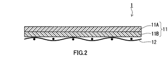
- Sectional drawing which shows one Embodiment of the waterproof sound-permeable membrane of this invention
- Sectional drawing which shows another embodiment of the waterproof sound-permeable membrane of this invention
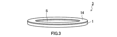
- the perspective view which shows an example of embodiment of the sound-permeable member of this invention
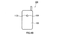
- the front view which shows an example of the mobile telephone which is an example of the electric equipment of this invention
- the rear view which shows an example of the mobile telephone which is an example of the electric equipment of this invention
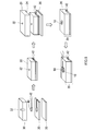
- Process chart showing measurement procedure of acoustic characteristics of waterproof sound-permeable membrane Sectional drawing explaining arrangement of waterproof sound-permeable membrane in measurement of acoustic characteristics
- the waterproof sound-permeable membrane 1 of this embodiment includes a porous membrane 11 and a support material 12.
- the porous membrane 11 is a resin porous membrane mainly containing PTFE.
- the “main component” refers to a component that is contained most in mass ratio.
- the support material 12 is integrated with the porous film 11 in a state where the porous film 11 is laminated.
- the support material 12 supports the porous membrane 11.
- the support material 12 is a mesh or net having a wire diameter of 45 to 60 ⁇ m in the whole support 12 and an opening of 700 to 1100 ⁇ m.
- the support material 12 that is a mesh or a net is integrated with the porous film 11 without being stretched in a state where the porous film 11 is laminated.
- the mesh or net that is the support member 12 has, for example, a lattice structure.
- the wire diameter of the warp yarn of the support member 12 and the wire diameter of the weft yarn of the support member 12 may be the same or different as long as they are within the above-mentioned range.
- the opening in the vertical direction of the support member 12 and the opening in the horizontal direction of the support member 12 may be the same as or different from each other as long as they are within the above range.
- the waterproof sound-permeable membrane 1 has characteristics that prevent water droplets from passing and allow gas such as water vapor to pass through due to the porous structure of the porous membrane 11. Moreover, the waterproof sound-permeable membrane 1 allows passage of sound. For this reason, the waterproof sound-permeable membrane 1 closes the opening of the housing of the electric device corresponding to the sounding part or the sound receiving part in an electric device provided with a sounding part such as a speaker or a buzzer or a sound receiving part such as a microphone. Can be arranged as follows. Thereby, the waterproofness and sound permeability of an electric equipment are securable. In order to enable the use of electrical equipment under various environmental conditions, it is required to improve the waterproofness of the electrical equipment. Therefore, the waterproof sound-permeable membrane is required to have high water pressure resistance.
- the waterproof sound-permeable membrane 1 of this embodiment has high water pressure resistance.
- the water pressure resistance measured based on JIS (Japanese Industrial Standards) L1092 B method is 20 kPa or more.
- the water pressure resistance of the porous membrane 11 and the waterproof sound-permeable membrane 1 is the same as that described above with a stainless mesh (opening diameter: 2 mm) provided on the opposite side of the pressure surface of the porous membrane 11 or the waterproof sound-permeable membrane 1. Measured based on the standard.
- the water pressure resistance (hereinafter referred to as “water pressure resistance”) of the waterproof sound-permeable membrane 1 thus measured is 20 kPa or more.
- the water pressure resistance of the waterproof sound-permeable membrane 1 is preferably 20 to 400 kPa, and more preferably 50 to 400 kPa.
- the waterproof sound-permeable membrane 1 has good acoustic characteristics. Specifically, the waterproof sound-permeable membrane 1 has an insertion loss of 5 dB or less with respect to a sound of 3000 Hz. For this reason, the waterproof sound-permeable membrane 1 exhibits good acoustic characteristics with low insertion loss for sound in a relatively high frequency region. For this reason, it is suppressed that the sound of the comparatively high frequency range transmitted from a sound source is attenuated by the waterproof sound-permeable membrane 1.
- the insertion loss is the difference between the sound pressure level when the waterproof sound-permeable membrane 1 is present in the path through which sound is transmitted and the sound pressure level when the waterproof sound-permeable film 1 is not present in the path through which sound is transmitted. Details of the method for measuring the acoustic characteristics of the waterproof sound-permeable membrane 1 will be described later.
- the lower limit of the insertion loss with respect to the 3000 Hz sound of the waterproof sound-permeable membrane 1 is not particularly limited.
- the porous membrane 11 can be manufactured, for example, as follows. First, a kneaded product of PTFE fine powder and molding aid is formed into a sheet by extrusion molding and rolling. In this state, the molding aid is removed from the sheet-like kneaded product to obtain a PTFE sheet. The porous membrane 11 can be obtained by stretching the PTFE sheet in the length direction and the width direction. The porous membrane 11 thus obtained has a porous structure having a large number of voids between fine fibers (fibrils) of PTFE as pores. The average pore diameter and porosity of the porous structure of the porous membrane 11 can be appropriately adjusted by changing the stretching conditions of the PTFE sheet.
- the average pore diameter of the porous membrane 11 is preferably 1 ⁇ m or less, more preferably 0.7 ⁇ m or less, and even more preferably 0.8 ⁇ m or less from the viewpoint of achieving both waterproofness and sound permeability of the waterproof sound-permeable membrane 1. 5 ⁇ m or less.
- the lower limit value of the average pore diameter of the porous membrane 11 is not particularly limited, but is, for example, 0.1 ⁇ m.
- the “average pore diameter” of the porous membrane 11 is a value measured in accordance with the provisions of ASTM (American Society for Testing Materials) F316-86.
- the average pore diameter of the porous membrane 11 can be measured using, for example, a commercially available measuring device (Perm-Porometer manufactured by Porous Material Co., Ltd.) conforming to the above-mentioned regulations.
- the surface density of the porous membrane 11 is preferably 2 to 10 g / m 2 , more preferably 2 to 8 g / m 2 , and further preferably 2 to 5 g / m 2 . .
- the surface density of the porous film 11 is preferably smaller.
- it is difficult to bond a double-sided tape to a single PTFE porous membrane or to punch a single PTFE porous membrane because the mechanical strength of the PTFE porous membrane is low.
- the strength of the PTFE porous membrane is low, there is a possibility that the membrane shrinks or the membrane tears due to tensile stress (line tension).
- the waterproof sound-permeable membrane 1 has excellent processability (handling property).
- the porous membrane 11 may be colored. Since the main component of the porous membrane 11 is PTFE, the original color of the porous membrane 11 is white. Therefore, when the waterproof sound-permeable membrane 1 is provided in the electrical device so that the porous membrane 11 closes the opening of the housing of the electrical device, the presence of the porous membrane 11 is conspicuous. Therefore, the porous membrane 11 is colored according to the color of the casing, so that the presence of the porous membrane 11 is less noticeable when the waterproof sound-permeable membrane 1 is disposed on the casing.
- the porous film 11 is colored, for example, black.
- the porous film 11 may be subjected to a liquid repellent treatment.
- the porous film 11 has good water repellency or good oil repellency.
- Such a porous membrane 11 is suitable for the use of the waterproof sound-permeable membrane 1.
- the liquid repellent treatment can be performed, for example, by a known method after the porous film 11 is colored.
- the liquid repellent used for the liquid repellent treatment is not particularly limited, and is typically a material containing a polymer having a perfluoroalkyl group.
- the support material 12 which is a mesh or a net is preferably made of a resin material having a Young's modulus of 0.2 to 7.0 GPa from the viewpoint of ensuring good handling characteristics of the waterproof sound-permeable membrane 1.
- a resin material include polyolefin, polyester, polyamide, fluororesin, and ultra high molecular weight polyethylene.
- the Young's modulus of the resin material forming the support material 12 is preferably 1.0 to 4.0 GPa, more preferably 1.5 to 3.1 GPa.
- the Young's modulus of the resin material is a value measured based on JIS K 7161-7164.
- polyester which is a resin material forming the support material 12 polyethylene terephthalate is preferable.
- the waterproof pressure is 20 kPa or more, and the insertion loss for sound of 3000 Hz is 5 dB or less. Sound membrane is easy to obtain.
- the waterproof sound-permeable membrane 1 can be produced by laminating the laminated body under a predetermined temperature condition and a predetermined pressure condition in a state where the porous film 11 and the support material 12 are laminated. . In this way, the porous membrane 11 and the support material 12 are integrated. As described above, since the porous membrane 11 is obtained by stretching a PTFE sheet, it is not necessary to further stretch the porous membrane 11 while being laminated on the support material 12. For this reason, the waterproof sound-permeable membrane 1 is formed without being stretched after the porous membrane 11 and the support material 12 are integrated. For this reason, the support material 12 is integrated with the porous membrane 11 without being stretched in a state where the porous membrane 11 is laminated. Thereby, the water pressure resistance of the waterproof sound-permeable membrane 1 can be enhanced.
- the waterproof sound-permeable membrane 1 may be configured so that the porous membrane 11 has a laminated structure in which a plurality of porous membranes are laminated.
- the porous film 11 has a laminated structure in which a plurality of porous films are laminated will be described.
- the waterproof sound-permeable membrane 1 of this embodiment is configured in the same manner as in the above-described embodiment, unless otherwise specified.
- the porous film 11 has a laminated structure of a first porous film 11A and a second porous film 11B. Further, each of the first porous film 11A and the second porous film 11B is produced by stretching a PTFE sheet in the length direction and the width direction as described above. For this reason, each of the first porous film 11A and the second porous film 11B has a porous structure in which a large number of voids between fine fibers (fibrils) of PTFE are pores.
- the first porous film 11A or the second porous film 11B may be colored in any color or may not be colored.
- the first porous membrane 11A forming one main surface of the waterproof sound-permeable membrane 1 may be colored black by the above-described coloring treatment, for example. In this case, if the waterproof sound-permeable membrane 1 is disposed in the opening of the casing of the electric device so that the first porous membrane 11A faces the outside of the casing of the electric device, the presence of the waterproof sound-permeable membrane 1 is not noticeable. .
- the waterproof sound-permeable membrane 1 may have a laminated structure in which three or more porous membranes are laminated. In this case, the porous membrane forming one main surface of the waterproof sound-permeable membrane 1 may be colored according to the color (for example, black) of the housing. Further, the first porous film 11A or the second porous film 11B may be subjected to a liquid repellent treatment as described above.
- the average pore diameter of each of the first porous film 11A and the second porous film 11B may be in the range described above as the average pore diameter of the porous film 11 of the waterproof sound-permeable membrane 1A. Further, the average pore diameters of the first porous membrane 11A and the second porous membrane 11B may be the same or different from each other. Moreover, from the viewpoint of ensuring sound transmission, the surface density of the porous film 11 formed by laminating a plurality of porous films (the first porous film 11A and the second porous film 11B) is preferably 2 to 10 g / cm 2 , more preferably 2 to 8 g / cm 2 , and further preferably 2 to 5 g / cm 2 .
- the sound-permeable member 3 is formed by attaching a ring-shaped membrane support material 14 to the peripheral portion of the disc-shaped waterproof sound-permeable membrane 1.
- the membrane support material 14 supports the waterproof sound-permeable membrane 1. That is, the sound permeable member 3 includes a waterproof sound permeable membrane 1 and a membrane support member 14 that supports the preventive sound permeable membrane 1.
- the waterproof sound-permeable membrane 1 can be reinforced and the sound-permeable member 3 can be easily handled.
- the membrane support member 14 can be attached to the housing of the electric device, the work of attaching the waterproof sound-permeable membrane 1 to the housing is improved.
- the shape of the membrane support 14 is not particularly limited as long as the waterproof sound-permeable membrane 1 can be supported.
- the material of the membrane support 14 is not particularly limited, and resin, metal, or a composite material thereof can be used.
- the joining method of the sound-permeable membrane 1 and the membrane support material 14 is not particularly limited, and for example, heat welding, ultrasonic welding, adhesion with an adhesive, and adhesion with a double-sided tape can be applied.
- the waterproof sound-permeable membrane 1 has a sound-permeable surface S.
- the sound-transmitting surface S is a region of the waterproof sound-transmitting membrane 1 that is exposed without being joined to other members, a housing of an electric device, or the like.
- the waterproof sound-permeable membrane 1 is arranged in the electric device so as to close the opening of the electric device case, most of the sound entering and exiting the inside of the electric device case is transmitted through the waterproof sound-permeable membrane 1. Pass through surface S. From the viewpoint of realizing miniaturization of the electrical equipment, it is preferable that the size of the sound-transmitting surface S of the waterproof sound-permeable membrane 1 is small.
- the maximum diameter of the sound-transmitting surface S of the waterproof sound-permeable membrane 1 is, for example, 0.5 to 4.0 mm, preferably 0.75 to 2.5 mm, and more preferably 1.0 to 2.0 mm. is there. Thus, the size of the sound-transmitting surface S of the waterproof sound-permeable membrane 1 is relatively small.
- the characteristic of the support material 12 of the waterproof sound-permeable membrane 1 of the present embodiment described above is that the waterproof sound-permeable membrane 1 has good water pressure resistance (water pressure resistance) when the sound-transmitting surface S is relatively small. 20 kPa or more) and good acoustic characteristics (insertion loss for sound of 3000 Hz is 5 dB or less).
- the maximum diameter of the sound-transmitting surface S means the maximum distance among the distances between any two points on the outer periphery of the sound-transmitting surface S.
- the electric device 100 is, for example, a mobile phone as shown in FIGS. 4A and 4B.
- the mobile phone 100 includes a housing 105, a speaker, a microphone, and a buzzer (not shown) provided inside the housing 105. That is, the electric device 100 includes a sound generation unit that is a speaker and a buzzer and a sound reception unit that is a microphone.
- the housing 105 has an opening 102 corresponding to a speaker, an opening 103 corresponding to a microphone, and an opening 104 corresponding to a buzzer.
- the waterproof sound-permeable membrane 1 or the sound-permeable member 3 is disposed so as to close the openings 102, 103, and 104. For this reason, the electric device 100 has good water pressure resistance and good acoustic characteristics.
- Air permeability The air permeability of the porous membrane or the waterproof sound-permeable membrane was evaluated based on the method B (Gurley method) of the air permeability measurement method defined in JIS (Japanese Industrial Standard) L 1096.
- the water pressure resistance of the porous membrane or the waterproof sound-permeable membrane was measured based on the B method (high water pressure method) described in JIS L 1092: 2009 using a water resistance tester.
- a resin is provided by providing a stainless steel mesh (opening diameter: 2 mm) on the opposite side of the pressure surface of the porous membrane or the waterproof sound-permeable membrane. With the deformation of the porous membrane suppressed to some extent, the water pressure resistance of the porous membrane or the waterproof sound-permeable membrane was measured.
- Liquid repellency A copy paper (plain paper) and a porous membrane or a waterproof sound-permeable membrane were laminated so that the copy paper was on the bottom, a drop of kerosene was dropped on the porous membrane using a dropper, and then left for 1 minute. Thereafter, the porous film was removed and the state of the copy paper was confirmed. When the copy paper was wet with kerosene, the liquid repellency was evaluated, and when the copy paper was not wet with kerosene, the liquid repellency was evaluated.
- the acoustic characteristics of the produced waterproof sound-permeable membrane were evaluated as follows. First, as shown in FIG. 5, a polystyrene simulated case 20 (outer dimensions 60 mm ⁇ 50 mm ⁇ 28 mm) imitating the case of a mobile phone was prepared. The simulated housing 20 has one speaker mounting hole 22 having a diameter of 2 mm and one conduction hole 24 for the speaker cable 42. The simulated housing 20 has no opening other than the speaker mounting hole 22 and the conduction hole 24. Next, as shown in FIG.
- a speaker 40 (SCG-16A, manufactured by Star Seimitsu Co., Ltd.) is attached to a filler 30 made of urethane sponge having a sound passage hole 32 having a diameter of 5 mm, and a simulated housing. Enclosed inside the body 20.
- the speaker cable 42 was led out of the simulated housing 20 from the conduction hole 24. Thereafter, the conduction hole 24 was closed with putty.
- the waterproof sound-permeable membrane 1 according to each example or comparative example, a PET film 5 having a thickness of 0.1 mm, a PET support material double-sided tape 6 (No. 5603, manufactured by Nitto Denko Corporation). , Thickness: 0.03 mm) and polyethylene foam support material double-sided tape 7 (Nitto Denko No. 57120B, thickness: 0.20 mm) was punched into an inner diameter of 2.5 mm and an outer diameter of 5.8 mm. Sample 10 for evaluation was produced. Then, this evaluation sample 10 was attached to the outside of the speaker mounting hole 22 of the simulated housing 20.
- the waterproof sound-permeable membrane 1 covers the entirety of the speaker mounting hole 22, and the waterproof sound-permeable membrane 1 does not cause a gap between the double-sided tape 7 and the simulated housing 20 and between the waterproof sound-permeable membrane 1 and the double-sided tape 7.
- the sound membrane 1 was attached to the simulated housing 20.
- a microphone 50 (Knowles Acoustic, SPM0405HD4H-W8) is installed above the waterproof sound-permeable membrane 1 so as to cover the waterproof sound-permeable membrane 1, and the microphone 50 is connected to an acoustic evaluation device (B & K, Multi-analyzer). System 3560-B-030). The distance between the speaker 40 and the microphone 50 was 21 mm.
- SSR analysis test signal: 20 Hz to 10 kHz, sweep
- the sound pressure level of the blank measured with the waterproof sound-permeable membrane 1 being broken and the through-hole being formed by removing the inner diameter portion of the waterproof sound-permeable membrane having a diameter of 2.5 mm was -21 dB at 1000 Hz. .
- the insertion loss is obtained from the test signal input to the speaker 40 from the acoustic evaluation apparatus and the signal received by the microphone 50, and measured with the waterproof sound-permeable membrane 1 attached from the sound pressure level of the blank. Obtained by subtracting the sound pressure level. It can be determined that the smaller the insertion loss is, the more the volume output from the speaker 40 is maintained.
- Example 1 100 parts by weight of PTFE fine powder (Daikin Kogyo Co., Ltd., F-104) and 20 parts by weight of hydrocarbon oil (Esso Co., Isopar M) are uniformly mixed, and the resulting mixture is compressed by a cylinder before ram. Extrusion was performed to obtain a sheet-like mixture. Next, the obtained sheet-like mixture was rolled to a thickness of 0.16 mm through a pair of metal rolls, and the molding aid was dried and removed by heating at 150 ° C. to obtain a PTFE sheet compact.
- PTFE fine powder Daikin Kogyo Co., Ltd., F-104
- hydrocarbon oil Esso Co., Isopar M
- the obtained PTFE sheet molded body was stretched in the longitudinal direction (rolling direction) at a stretching temperature of 260 ° C. and a stretching ratio of 10 times to obtain a PTFE porous membrane.
- a black dye manufactured by Orient Chemical Industry Co., Ltd., SP BLACK 91-L, ethanol dilution solution 25% by weight
- 80 parts by weight of ethanol (purity 95%) as a solvent for the dye
- the oil repellent treatment liquid was prepared as follows. 100 g of a compound having a linear fluoroalkyl group represented by the following (formula 1), 0.1 g of azobisisobutyronitrile as a polymerization initiator, and 300 g of a solvent (manufactured by Shin-Etsu Chemical Co., Ltd., FS thinner) are introduced into a nitrogen introduction tube.
- the PTFE porous membrane subjected to the liquid repellent treatment was stretched in the width direction (direction perpendicular to the longitudinal direction) at a stretching temperature of 150 ° C. and a stretching ratio of 10 times, and the PTFE porous membrane was further melted at a melting point (327 ° C.) of PTFE.
- the porous film according to Example 1 (PTFE porous film) was obtained.
- the obtained porous membrane had an average pore size of 0.5 ⁇ m, an areal density of 5 g / m 2 , an air permeability of 1.0 sec / 100 mL, and a water pressure resistance of 80 kPa.
- the obtained porous membrane and a mesh made of polyethylene terephthalate (PET) (manufactured by Nippon Special Textile Co., Ltd., 30-30), which is a support material for the porous membrane, are heated using a hot press process.
- PET polyethylene terephthalate
- the mesh made of PET was integrated without stretching.
- a waterproof sound-permeable membrane according to Example 1 was obtained.
- the integration of the porous membrane and the mesh made of PET was performed by pressurizing at a heating temperature of 200 ° C. and a pressure of 0.5 MPa for 2 seconds.
- the surface density of the obtained waterproof sound-permeable membrane was 13.5 g / m 2
- the air permeability was 1.0 sec / 100 mL
- the water pressure resistance was 80 kPa
- the liquid repellency was “Yes”.
- Example 2 In the same manner as in Example 1 except that a PET mesh having a wire diameter of 55 ⁇ m and an opening of 1000 ⁇ m was used as a support material (Nippon Special Textile Co., Ltd., Hana 24-30), A sound membrane was obtained.
- Comparative Example 1 The waterproof sound transmission according to Comparative Example 1 was performed in the same manner as in Example 1 except that a polyester mesh (manufactured by Nippon Special Textile Co., Ltd., LX 100SS) having a wire diameter of 48 ⁇ m and an opening of 206 ⁇ m was used as the support material. A membrane was obtained.
- a polyester mesh manufactured by Nippon Special Textile Co., Ltd., LX 100SS
- Comparative Example 2 was carried out in the same manner as in Example 1 except that a polypropylene (PP) mesh (Delstar, Delnet RB0707-30P) having a wire diameter of 85 ⁇ m and an opening of 300 ⁇ m ⁇ 800 ⁇ m was used as the support material. Such a waterproof sound-permeable membrane was obtained.
- PP polypropylene
- Example 2 Comparative Example 1 and Comparative Example 2, the heating temperature is a temperature suitable for the material of each support material, and the heating time and the pressurizing pressure are the same conditions as in Example 1, and the porous membrane And the support material were integrated.
- ⁇ Comparative Example 3> A mixture of 100 parts by weight of PTFE fine powder (Daikin Kogyo Co., Ltd., Polyflon F-104U) and 25 parts by weight of hydrocarbon oil (Isopar M, manufactured by Esso Petroleum Co., Ltd.) uniformly mixed is extruded into a paste to be preformed into a stick. Went. This preform was passed between a pair of metal rolling rolls to obtain a green tape having a thickness of 0.2 mm and a width of 370 mm. Next, this unfired tape was stretched 20 times in the longitudinal direction at a temperature (375 ° C.) higher than the melting point of PTFE by a roll stretching machine to obtain a longitudinally stretched fired PTFE sheet.
- PTFE fine powder Daikin Kogyo Co., Ltd., Polyflon F-104U
- hydrocarbon oil Isopar M, manufactured by Esso Petroleum Co., Ltd.
- a PP net having a lattice structure having an opening (mesh size) of 300 ⁇ m ⁇ 800 ⁇ m and a wire diameter (fiber system) of 85 ⁇ m as a support material is placed on one of the above-mentioned longitudinally stretched sintered PTFE sheets. Lamination was performed on the main surface at a temperature higher than the melting point of the net (180 ° C.) and a pressure of 5 kg / cm 2 . Next, the laminated PTFE sheet is colored with a treatment agent in which 100 parts by weight of a water repellent (trade name: Scotchguard FX3576) and 190 parts by weight of a black dye (trade name: Bali First Black) are mixed with a kiss coater. Processed.
- a water repellent trade name: Scotchguard FX3576
- a black dye trade name: Bali First Black
- this PTFE sheet was stretched 3 times in the transverse direction at a temperature of 130 ° C. by a tenter to obtain a waterproof sound-permeable membrane according to Comparative Example 3. That is, in the waterproof sound-permeable membrane according to Comparative Example 3, the PP net as the support material is stretched three times in the lateral direction while being laminated on the PTFE sheet as the porous membrane. This lateral stretching changed the lateral opening of the PP net from 300 ⁇ m to 900 ⁇ m. The wire diameter of the yarn extending in the lateral direction of the PP net changed from 85 ⁇ m to 49 ⁇ m. On the other hand, the wire diameter of the yarn extending in the longitudinal direction of the PP net remained 85 ⁇ m.
- a waterproof sound-permeable membrane according to Comparative Example 4 was obtained in the same manner as described in Example 1 of JP-A-10-165787. Specifically, the waterproof sound-permeable membrane according to Comparative Example 4 was obtained as follows. First, a mixture of 100 parts by weight of PTFE fine powder (Daikin Kogyo Co., polyflon F-104U) and 25 parts by weight of hydrocarbon oil (Isopar M, Esso Petroleum Co., Ltd.) uniformly mixed is paste-extruded and preformed into a rod shape. Went. This preform was passed between a pair of metal rolling rolls to obtain a green tape having a thickness of 0.2 mm and a width of 370 mm.
- PTFE fine powder Daikin Kogyo Co., polyflon F-104U
- hydrocarbon oil Isopar M, Esso Petroleum Co., Ltd.
- this molded product was stretched 50 times in the longitudinal direction at a temperature (375 ° C.) higher than the melting point of PTFE by a roll stretching machine to obtain a longitudinally stretched baked PTFE sheet.
- a PP net having a lattice structure with an opening (mesh size) of 1000 ⁇ m and a wire diameter (fiber system) of 85 ⁇ m was stretched 5 times in the machine direction at a temperature (130 ° C.) below the melting point of the net.
- the opening in the longitudinal direction of the PP net changed from 1000 ⁇ m to 5000 ⁇ m.
- the wire diameter of the yarn extending in the longitudinal direction of the PP net changed from 85 ⁇ m to 38 ⁇ m.
- this PP net was laminated on one main surface of the longitudinally stretched baked PTFE sheet at a temperature equal to or higher than the melting point of the net (180 ° C.) and a pressure of 5 kg / cm 2 .
- the laminated PTFE sheet is treated with a treatment agent in which 100 parts by weight of a water repellent (trade name: Scotchguard FX3576) and 190 parts by weight of a black dye (trade name: Bali First Black) are mixed by a kiss coater.
- a coloring process was performed.
- this PTFE sheet was stretched 6 times in the transverse direction at a temperature of 130 ° C. by a tenter to obtain a waterproof sound-permeable membrane according to Comparative Example 4. With this stretching, the lateral opening of the PP net changed from 1000 ⁇ m to 6000 ⁇ m. Further, the diameter of the yarn extending in the lateral direction of the PP net changed from 85 ⁇ m to 35 ⁇ m.
- Table 1 shows the characteristics of the waterproof sound-permeable membrane support material, water pressure resistance and acoustic characteristics of each example and each comparative example.
- Table 1 shows the insertion loss of the waterproof sound-permeable membranes of Examples 1 and 2 with respect to the sound of 3000 Hz.
- the waterproof sound-permeable membranes of Comparative Example 1 and Comparative Example 2 were 3000 Hz.
- the insertion loss for the sound of was greater than 5 dB. For this reason, it was shown that the waterproof sound-permeable membranes of Example 1 and Example 2 have good acoustic characteristics.
- the water-proof pressure of the waterproof sound-permeable membrane of Example 1 and Example 2 was 80 kPa
- the water-proof pressure of the waterproof sound-permeable membrane of Comparative Example 3 was 18 kPa
- the water pressure was 6 kPa.
- the waterproof sound-permeable membranes of Example 1 and Example 2 have good water pressure resistance characteristics.
- the insertion loss with respect to the sound of 1000 Hz and the insertion loss with respect to the sound of 3000 Hz were higher than the insertion loss of the waterproof sound-permeable membrane of Example 1 and Example 2.
- the waterproof sound-permeable membranes of Example 1 and Example 2 have better acoustic properties than the waterproof sound-permeable membrane of Comparative Example 3.
- the waterproof sound-permeable membrane of Comparative Example 4 has good acoustic characteristics.
- the maximum diameter of the sound-permeable surface of the waterproof sound-permeable membrane is 2.5 mm, for example, the fiber (thread) of the PP net is always sound-transmitted by the waterproof sound-permeable membrane It is difficult to produce a waterproof sound-permeable membrane so that it exists on the surface. For this reason, it is difficult to mass-produce the waterproof sound-permeable membrane of Comparative Example 4.
Landscapes
- Engineering & Computer Science (AREA)
- Signal Processing (AREA)
- Physics & Mathematics (AREA)
- Acoustics & Sound (AREA)
- Details Of Audible-Bandwidth Transducers (AREA)
- Manufacture Of Porous Articles, And Recovery And Treatment Of Waste Products (AREA)
- Laminated Bodies (AREA)
- Telephone Set Structure (AREA)
- Health & Medical Sciences (AREA)
- General Health & Medical Sciences (AREA)
- Otolaryngology (AREA)
Abstract
Description
ポリテトラフルオロエチレンを主成分とする多孔質膜と、
前記多孔質膜を積層した状態で延伸されることなく前記多孔質膜と一体化されており、前記多孔質膜を支持している支持材と、を備え、
前記支持材は、線径が前記支持材全体において45~60μmであり、かつ、オープニングが700~1100μmであるメッシュ又はネットであり、
JIS L1092のB法(高水圧法)に基づいて測定される耐水圧が20kPa以上である、防水通音膜を提供する。
上記の防水通音膜と、
前記防水通音膜を支持している膜支持材と、を備える通音部材を提供する。
発音部又は受音部を備えた電気機器であって、
前記発音部又は前記受音部に対応する筐体の開口を塞ぐように、上記の防水通音膜又は上記の通音部材が配置されている、電気機器を提供する。
多孔質膜又は防水通音膜の通気度をJIS(日本工業規格) L 1096に規定されている通気性測定法のB法(ガーレー法)に準拠して評価した。
多孔質膜又は防水通音膜の耐水圧を、耐水度試験機を用いて、JIS L 1092:2009に記載されているB法(高水圧法)に基づいて測定した。ただし、この規定に示された試験片の面積では多孔質膜が著しく変形するので、ステンレスメッシュ(開口径:2mm)を多孔質膜又は防水通音膜の加圧面の反対側に設けることによって樹脂多孔質膜の変形をある程度抑制した状態で、多孔質膜又は防水通音膜の耐水圧を測定した。
コピー用紙(普通紙)と、多孔質膜又は防水通音膜とを、コピー用紙が下になるように積層し、スポイトを用いて多孔質膜に灯油を一滴垂らした後1分間放置した。その後、多孔質膜を取り除いてコピー用紙の状態を確認し、コピー用紙が灯油で濡れている場合を撥液性なし、コピー用紙が灯油で濡れていない場合を撥液性ありと評価した。
作製した防水通音膜の音響特性を以下のように評価した。最初に、図5に示すように、携帯電話の筐体を模したポリスチレン製の模擬筐体20(外形60mm×50mm×28mm)を準備した。この模擬筐体20は、径が2mmであるスピーカー取付穴22及びスピーカーケーブル42の導通孔24を1つずつ有している。模擬筐体20は、スピーカー取付穴22及び導通孔24以外に開口を有していない。次に、図5に示すように、径が5mmの通音孔32を有する、ウレタン製のスポンジで形成された充填材30にスピーカー40(スター精密社製、SCG-16A)を取り付け、模擬筐体20の内部に封入した。スピーカーケーブル42を導通孔24から模擬筐体20の外部へ導き出した。その後、導通孔24をパテで塞いだ。
PTFEファインパウダー(ダイキン工業社製、F-104)100重量部と、炭化水素油(エッソ社製、アイソパーM)20重量部とを均一に混合し、得られた混合物をシリンダーによって圧縮した後にラム押出しを行ってシート状の混合物を得た。次に、得られたシート状の混合物を一対の金属ロールを通して厚さ0.16mmに圧延し、さらに150℃の加熱によって成形助剤を乾燥除去してPTFEのシート成形体を得た。
CH2=CHCOOCH2CH2C6F13 (式1)
支持材として、線径が55μm及びオープニングが1000μmであるPET製のメッシュ(日本特殊織物社製、華24-30)を用いた以外は実施例1と同様にして、実施例2に係る防水通音膜を得た。
支持材として、線径が48μm及びオープニングが206μmであるポリエステル製のメッシュ(日本特殊織物社製、LX 100SS)を用いた以外は、実施例1と同様にして、比較例1に係る防水通音膜を得た。
支持材として、線径が85μm及びオープニング300μm×800μmであるポリプロピレン(PP)製のメッシュ(デルスター社製、デルネットRB0707-30P)を用いた以外は、実施例1と同様にして比較例2に係る防水通音膜を得た。
PTFEファインパウダー(ダイキン工業社製、ポリフロンF-104U)100重量部に炭化水素油(アイソパーM、エッソ石油社製)25重量部を均一に混合した混和物をペースト状に押出して棒状に予備形成を行った。この予備形成物を、一対の金属製圧延ロールの間に通し、厚み0.2mm、幅370mmの未焼成テープを得た。次に、この未焼成テープをロール延伸機によってPTFEの融点以上の温度(375℃)で縦方向に20倍に延伸し、縦方向延伸済焼成PTFEシートを得た。次に、支持材である、オープニング(網目の大きさ)が300μm×800μm、線径(繊維系)が85μmである格子構造のPP製のネットを上記の縦方向延伸済焼成PTFEシートの一方の主面にネットの融点以上の温度(180℃)、圧力5kg/cm2でラミネートした。次に、ラミネート後のPTFEシートをキスコーターにより撥水剤(商品名:スコッチガードFX3576)100重量部と黒色染料(商品名:バリファーストブラック)190重量部とが混合された処理剤を用いて着色処理を行った。着色処理後、このPTFEシートをテンターによって温度130℃で横方向に3倍延伸し、比較例3に係る防水通音膜を得た。すなわち、比較例3に係る防水通音膜において、支持材であるPP製のネットは、多孔質膜であるPTFEシートに積層された状態で横方向に3倍に延伸されている。この横方向の延伸によって、PP製のネットの横方向のオープニングは300μmから900μmへと変化した。また、PP製のネットの横方向に延びる糸の線径は85μmから49μmへ変化した。一方、PP製ネットの縦方向に延びる糸の線径は85μmのままであった。
特開平10-165787号公報の実施例1に記載の方法と同様にして、比較例4に係る防水通音膜を得た。具体的には、以下のようにして比較例4に係る防水通音膜を得た。まず、PTFEファインパウダー(ダイキン工業社製、ポリフロンF-104U)100重量部に炭化水素油(アイソパーM、エッソ石油社製)25重量部を均一に混合した混和物をペースト押し出して棒状に予備成形を行った。この予備成形物を、一対の金属製圧延ロールの間に通し、厚み0.2mm、幅370mmの未焼成テープを得た。ついで、この成形物を、ロール延伸機によってPTFEの融点以上の温度(375℃)で縦方向に50倍延伸し、縦方向延伸済焼成PTFEシートを得た。一方、オープニング(網目の大きさ)が1000μm、線径(繊維系)が85μmである格子構造のPP製のネットをそのネットの融点以下の温度(130℃)で縦方向に5倍延伸した。この延伸によって、PP製のネットの縦方向のオープニングは1000μmから5000μmへと変化した。また、PP製のネットの縦方向に延びる糸の線径は85μmから38μmへ変化した。

Claims (6)
- ポリテトラフルオロエチレンを主成分とする多孔質膜と、
前記多孔質膜を積層した状態で延伸されることなく前記多孔質膜と一体化されており、前記多孔質膜を支持している支持材と、を備え、
前記支持材は、線径が前記支持材全体において45~60μmであり、かつ、オープニングが700~1100μmであるメッシュ又はネットであり、
JIS L1092のB法(高水圧法)に基づいて測定される耐水圧が20kPa以上である、防水通音膜。 - 3000Hzの音に対する挿入損失が5dB以下である、請求項1に記載の防水通音膜。
- 前記支持材は、ヤング率が0.2~7.0GPaである樹脂材料によって形成されている請求項1又は2に記載の防水通音膜。
- 前記多孔質膜の面密度が2.0~10.0g/m2である、請求項1に記載の防水通音膜。
- 請求項1に記載の防水通音膜と、
前記防水通音膜を支持している膜支持材と、を備える通音部材。 - 発音部又は受音部を備えた電気機器であって、
前記発音部又は前記受音部に対応する筐体の開口を塞ぐように、請求項1に記載の防水通音膜又は請求項5に記載の通音部材が配置されている、電気機器。
Priority Applications (3)
| Application Number | Priority Date | Filing Date | Title |
|---|---|---|---|
| KR1020157025553A KR20150122693A (ko) | 2013-02-25 | 2013-10-28 | 방수 통음막, 통음 부재 및 전기 기기 |
| CN201380073765.1A CN105009603A (zh) | 2013-02-25 | 2013-10-28 | 防水透声膜、透声构件及电气设备 |
| US14/766,542 US9578402B2 (en) | 2013-02-25 | 2013-10-28 | Waterproof sound-transmitting membrane, sound-transmitting member, and electrical device |
Applications Claiming Priority (2)
| Application Number | Priority Date | Filing Date | Title |
|---|---|---|---|
| JP2013-035079 | 2013-02-25 | ||
| JP2013035079A JP6118131B2 (ja) | 2013-02-25 | 2013-02-25 | 防水通音膜、通音部材、及び電気機器 |
Publications (1)
| Publication Number | Publication Date |
|---|---|
| WO2014128799A1 true WO2014128799A1 (ja) | 2014-08-28 |
Family
ID=51390639
Family Applications (1)
| Application Number | Title | Priority Date | Filing Date |
|---|---|---|---|
| PCT/JP2013/006350 Ceased WO2014128799A1 (ja) | 2013-02-25 | 2013-10-28 | 防水通音膜、通音部材、及び電気機器 |
Country Status (6)
| Country | Link |
|---|---|
| US (1) | US9578402B2 (ja) |
| JP (1) | JP6118131B2 (ja) |
| KR (1) | KR20150122693A (ja) |
| CN (1) | CN105009603A (ja) |
| TW (1) | TW201440532A (ja) |
| WO (1) | WO2014128799A1 (ja) |
Cited By (1)
| Publication number | Priority date | Publication date | Assignee | Title |
|---|---|---|---|---|
| CN116783063A (zh) * | 2021-01-19 | 2023-09-19 | 阿莫绿色技术有限公司 | 防水传声片材及制造防水传声片材的方法 |
Families Citing this family (17)
| Publication number | Priority date | Publication date | Assignee | Title |
|---|---|---|---|---|
| CN105682914A (zh) * | 2013-10-15 | 2016-06-15 | 唐纳森公司 | 用于声音放出的微孔膜层压物 |
| WO2015068357A1 (ja) * | 2013-11-07 | 2015-05-14 | 日東電工株式会社 | 防水通音膜および電子機器 |
| JP6472182B2 (ja) * | 2014-07-15 | 2019-02-20 | 日東電工株式会社 | 防水部材及びその防水部材を備えた電子機器 |
| JP6581876B2 (ja) * | 2015-10-07 | 2019-09-25 | 中興化成工業株式会社 | 通気膜及びマイクロフォン |
| WO2017090246A1 (ja) * | 2015-11-24 | 2017-06-01 | 日東電工株式会社 | 防水通音膜、防水通音部材及び電子機器 |
| WO2017196101A2 (ko) * | 2016-05-13 | 2017-11-16 | 주식회사 아모그린텍 | 방수통음시트 |
| KR101807681B1 (ko) * | 2016-05-13 | 2017-12-13 | 주식회사 아모그린텍 | 방수통음시트 |
| JP6656110B2 (ja) * | 2016-07-27 | 2020-03-04 | 日本ゴア株式会社 | 防水通音カバー、防水通音カバー部材および音響装置 |
| US20180213340A1 (en) * | 2017-01-26 | 2018-07-26 | W. L. Gore & Associates, Inc. | High throughput acoustic vent structure test apparatus |
| CN107182020B (zh) * | 2017-06-29 | 2020-07-03 | 深圳市一禾音视频科技有限公司 | 平板音响安装方法 |
| CN108481865A (zh) * | 2018-04-13 | 2018-09-04 | 深圳昌茂粘胶新材料有限公司 | 一种防水透气呼吸膜及其制备方法 |
| DE112020002143T5 (de) * | 2019-04-26 | 2022-02-17 | Nitto Denko Corporation | Wasserdichte membran, wasserdichtes element, das diese umfasst, und elektronische vorrichtung |
| CN113748687A (zh) * | 2019-04-26 | 2021-12-03 | 日东电工株式会社 | 转换元件构件、具有该转换元件构件的转换元件模块以及电子设备 |
| US10741160B1 (en) * | 2019-09-25 | 2020-08-11 | W. L. Gore & Associates, Inc. | Acoustically resistive supported membrane assemblies |
| US11417311B2 (en) * | 2020-08-03 | 2022-08-16 | W. L. Gore & Associates, Inc. | Acoustically resistive supported membrane assemblies including at least one support structure |
| US12576367B2 (en) | 2021-08-30 | 2026-03-17 | W. L. Gore & Associates, Inc. | Polyethylene membrane acoustic assembly |
| US20250389060A1 (en) * | 2022-07-06 | 2025-12-25 | Saati S.P.A. | Improved textile protective element for use in acoustic components of electronic devices and acoustic component provided with this element inside |
Citations (6)
| Publication number | Priority date | Publication date | Assignee | Title |
|---|---|---|---|---|
| JP2003503991A (ja) * | 1999-07-07 | 2003-01-28 | ゴア エンタープライズ ホールディングス,インコーポレイティド | 音響保護カバーアセンブリ |
| JP2003250188A (ja) * | 2002-02-25 | 2003-09-05 | Nitto Denko Corp | 通気性通音膜 |
| JP2004083811A (ja) * | 2002-08-28 | 2004-03-18 | Nitto Denko Corp | 防水通音膜 |
| JP2009111993A (ja) * | 2007-10-09 | 2009-05-21 | Nitto Denko Corp | 防水通音膜を用いた通音部材およびその製造方法 |
| WO2011132062A1 (en) * | 2010-04-21 | 2011-10-27 | Saati S.P.A. | Textile laminar structure for making acoustic components |
| JP2012025160A (ja) * | 2010-07-23 | 2012-02-09 | Ef-Materials Industries Inc | 防水防塵薄膜アセンブリ及びそれを用いた装置 |
Family Cites Families (9)
| Publication number | Priority date | Publication date | Assignee | Title |
|---|---|---|---|---|
| US5828012A (en) * | 1996-05-31 | 1998-10-27 | W. L. Gore & Associates, Inc. | Protective cover assembly having enhanced acoustical characteristics |
| JPH10165787A (ja) | 1996-12-11 | 1998-06-23 | Nitto Denko Corp | ポリテトラフルオロエチレン多孔質膜およびその製造方法 |
| JP2003053872A (ja) | 2001-08-13 | 2003-02-26 | Nitto Denko Corp | 通気性通音膜 |
| WO2004046214A2 (en) * | 2002-10-15 | 2004-06-03 | Exxonmobil Chemical Patents Inc. | Multiple catalyst system for olefin polymerization and polymers produced therefrom |
| JP4708134B2 (ja) * | 2005-09-14 | 2011-06-22 | 日東電工株式会社 | 通音膜、通音膜付き電子部品及びその電子部品を実装した回路基板の製造方法 |
| JP4874383B2 (ja) * | 2009-12-01 | 2012-02-15 | 日本ゴア株式会社 | 通気フィルター、該通気フィルターの固定方法、および電気装置の製造方法。 |
| JP2011227624A (ja) * | 2010-04-16 | 2011-11-10 | Canon Inc | プリントサーバおよび印刷装置、ネットワーク印刷システムと印刷方法 |
| CN202071421U (zh) * | 2011-05-10 | 2011-12-14 | 常州市泛亚微透科技有限公司 | 用于防水防尘透声的膨体聚四氟乙烯的微孔薄膜复合无纺布的改性材料膜 |
| EP2566189B1 (en) * | 2011-08-30 | 2014-03-05 | Harman International Industries Ltd. | Loudspeaker arrangement |
-
2013
- 2013-02-25 JP JP2013035079A patent/JP6118131B2/ja active Active
- 2013-10-28 WO PCT/JP2013/006350 patent/WO2014128799A1/ja not_active Ceased
- 2013-10-28 KR KR1020157025553A patent/KR20150122693A/ko not_active Withdrawn
- 2013-10-28 CN CN201380073765.1A patent/CN105009603A/zh active Pending
- 2013-10-28 US US14/766,542 patent/US9578402B2/en active Active
- 2013-11-01 TW TW102139723A patent/TW201440532A/zh unknown
Patent Citations (6)
| Publication number | Priority date | Publication date | Assignee | Title |
|---|---|---|---|---|
| JP2003503991A (ja) * | 1999-07-07 | 2003-01-28 | ゴア エンタープライズ ホールディングス,インコーポレイティド | 音響保護カバーアセンブリ |
| JP2003250188A (ja) * | 2002-02-25 | 2003-09-05 | Nitto Denko Corp | 通気性通音膜 |
| JP2004083811A (ja) * | 2002-08-28 | 2004-03-18 | Nitto Denko Corp | 防水通音膜 |
| JP2009111993A (ja) * | 2007-10-09 | 2009-05-21 | Nitto Denko Corp | 防水通音膜を用いた通音部材およびその製造方法 |
| WO2011132062A1 (en) * | 2010-04-21 | 2011-10-27 | Saati S.P.A. | Textile laminar structure for making acoustic components |
| JP2012025160A (ja) * | 2010-07-23 | 2012-02-09 | Ef-Materials Industries Inc | 防水防塵薄膜アセンブリ及びそれを用いた装置 |
Cited By (1)
| Publication number | Priority date | Publication date | Assignee | Title |
|---|---|---|---|---|
| CN116783063A (zh) * | 2021-01-19 | 2023-09-19 | 阿莫绿色技术有限公司 | 防水传声片材及制造防水传声片材的方法 |
Also Published As
| Publication number | Publication date |
|---|---|
| JP2014165672A (ja) | 2014-09-08 |
| KR20150122693A (ko) | 2015-11-02 |
| US20150373439A1 (en) | 2015-12-24 |
| JP6118131B2 (ja) | 2017-04-19 |
| CN105009603A (zh) | 2015-10-28 |
| TW201440532A (zh) | 2014-10-16 |
| US9578402B2 (en) | 2017-02-21 |
Similar Documents
| Publication | Publication Date | Title |
|---|---|---|
| JP6118131B2 (ja) | 防水通音膜、通音部材、及び電気機器 | |
| JP5947655B2 (ja) | ポリテトラフルオロエチレン多孔質膜、並びに、それを用いた通気膜および通気部材 | |
| US8739926B1 (en) | Sound-transmitting membrane and electronic device equipped with sound-transmitting membrane | |
| JP6438733B2 (ja) | 防水通音膜および電子機器 | |
| KR102569879B1 (ko) | 방수 통음막, 방수 통음 부재 및 전자 기기 | |
| KR101249195B1 (ko) | 방수 통음막과 그 제조 방법 및 그것을 사용한 전기 제품 | |
| JP6324109B2 (ja) | 防水通音膜の製造方法、防水通音膜及び電子機器 |
Legal Events
| Date | Code | Title | Description |
|---|---|---|---|
| 121 | Ep: the epo has been informed by wipo that ep was designated in this application |
Ref document number: 13875931 Country of ref document: EP Kind code of ref document: A1 |
|
| WWE | Wipo information: entry into national phase |
Ref document number: 14766542 Country of ref document: US |
|
| NENP | Non-entry into the national phase |
Ref country code: DE |
|
| ENP | Entry into the national phase |
Ref document number: 20157025553 Country of ref document: KR Kind code of ref document: A |
|
| 122 | Ep: pct application non-entry in european phase |
Ref document number: 13875931 Country of ref document: EP Kind code of ref document: A1 |