WO2014126239A1 - 地下構造物用蓋 - Google Patents
地下構造物用蓋 Download PDFInfo
- Publication number
- WO2014126239A1 WO2014126239A1 PCT/JP2014/053636 JP2014053636W WO2014126239A1 WO 2014126239 A1 WO2014126239 A1 WO 2014126239A1 JP 2014053636 W JP2014053636 W JP 2014053636W WO 2014126239 A1 WO2014126239 A1 WO 2014126239A1
- Authority
- WO
- WIPO (PCT)
- Prior art keywords
- lid
- receiving frame
- surface portion
- main body
- outer peripheral
- Prior art date
Links
Images


Classifications
-
- E—FIXED CONSTRUCTIONS
- E02—HYDRAULIC ENGINEERING; FOUNDATIONS; SOIL SHIFTING
- E02D—FOUNDATIONS; EXCAVATIONS; EMBANKMENTS; UNDERGROUND OR UNDERWATER STRUCTURES
- E02D29/00—Independent underground or underwater structures; Retaining walls
- E02D29/12—Manhole shafts; Other inspection or access chambers; Accessories therefor
- E02D29/14—Covers for manholes or the like; Frames for covers
- E02D29/1472—Cover entirely made of synthetic material
-
- E—FIXED CONSTRUCTIONS
- E02—HYDRAULIC ENGINEERING; FOUNDATIONS; SOIL SHIFTING
- E02D—FOUNDATIONS; EXCAVATIONS; EMBANKMENTS; UNDERGROUND OR UNDERWATER STRUCTURES
- E02D29/00—Independent underground or underwater structures; Retaining walls
- E02D29/12—Manhole shafts; Other inspection or access chambers; Accessories therefor
- E02D29/14—Covers for manholes or the like; Frames for covers
- E02D29/149—Annular gaskets
-
- E—FIXED CONSTRUCTIONS
- E03—WATER SUPPLY; SEWERAGE
- E03F—SEWERS; CESSPOOLS
- E03F5/00—Sewerage structures
- E03F5/02—Manhole shafts or other inspection chambers; Snow-filling openings; accessories
Definitions
- the present invention relates to a lid for an underground structure including a lid main body and a receiving frame that supports the lid main body so that the lid main body can be opened and closed.
- underground structure lid refers to a manhole cover, large iron cover, sewage culm lid that can be opened and closed so that an opening through the ground can be opened and closed.
- the outer diameter of the lid body is slightly smaller than the inner diameter of the receiving frame, and the outer peripheral portion of the lid main body and the inner peripheral portion of the receiving frame are substantially vertical surfaces and protrude from the inner periphery of the receiving frame.
- cover main body with the made shelf part is known.
- the outer diameter of the lid body and the inner diameter of the receiving frame are made the same diameter, and the outer peripheral portion of the lid body and the inner peripheral portion of the receiving frame are formed with a steep slope downwardly, and the lid body is used as the receiving frame.
- the thing of the gradient receiving structure made to bite in is known.
- Patent Document 1 discloses that the inclination angle of the outer peripheral portion of the lid main body and the inclined surface of the inner peripheral portion of the receiving frame with respect to the vertical is 5 ° to 10 °.
- the height of the gradient surface of the outer peripheral part of a cover main body is made smaller than the height of the gradient surface of the inner peripheral part of a receiving frame.
- the angle of an inclined surface as mentioned above, the sufficient biting force with respect to the receiving frame of a lid body can be ensured, and the shakiness, vibration, and noise of a lid body are remarkable.
- the problem to be solved by the present invention is that the lid body can be prevented from rattling, vibration, and noise, and an excessive bite force to the receiving frame of the lid body can be prevented to generate an appropriate amount of labor. It is an object of the present invention to provide a lid for an underground structure that can be opened with a lid and can prevent the lid body from sliding up with respect to the receiving frame.
- a lid for an underground structure is a lid for an underground structure that includes a lid body and a receiving frame that supports the lid body so as to be openable and closable at an inner periphery thereof.
- the inner peripheral portion is formed with a receiving frame first surface portion formed by reducing the diameter toward the lower side of the receiving frame with a gentle gradient, and toward the lower side of the receiving frame with a steeper slope than the receiving frame first surface portion below the receiving frame first surface portion.
- a receiving frame second surface portion formed by reducing the diameter, and the outer peripheral portion of the lid body is formed by reducing the diameter toward the lower side of the lid body with a gentle gradient, and the lid first surface portion.
- a lid second surface portion formed by reducing the diameter vertically toward the lower portion of the lid body or with a steeper slope than the second surface portion of the receiving frame toward the lower portion of the lid body.
- the lid for an underground structure is a lid for an underground structure that includes a lid body and a receiving frame that supports the lid body so that the lid body can be opened and closed.
- a receiving frame first surface portion formed by reducing the diameter toward the lower side of the receiving frame with a gradient, and a diameter reducing toward the lower side of the receiving frame with a steeper slope than the receiving frame first surface portion below the receiving frame first surface portion.
- a receiving frame second surface portion, and a receiving frame third surface portion formed by reducing the diameter toward the lower portion of the receiving frame with a different gradient from the receiving frame second surface portion below the receiving frame second surface portion, and the outer peripheral portion of the lid body is The lid first surface portion formed by reducing the diameter toward the lower side of the lid main body with a gentle gradient, and below the lid first surface portion, vertically toward the lower side of the lid main body or steeper than the receiving frame second surface portion.
- the lid second surface portion formed by reducing the diameter toward the lower side of the lid body with a slight gradient, and the lid second surface And a lid third surface portion formed by reducing the diameter toward the lower side of the lid body with a gradient different from that of the lid second surface portion.
- the lid first surface portion is the receiving frame first. While being supported by the surface portion, at least one of the lid second surface portion and the lid third surface portion and at least one of the receiving frame second surface portion and the receiving frame third surface portion are the outer peripheral portion of the lid main body and the inner peripheral portion of the receiving frame. Are pressed against each other by a pressing force caused by elastic deformation of at least one of the above.
- the lid for an underground structure is a lid for an underground structure that includes a lid body and a receiving frame that supports the lid body so that the lid body can be opened and closed.
- a receiving frame first surface portion formed by reducing the diameter toward the lower portion of the receiving frame with a gradient, a receiving frame second surface portion formed below the receiving frame first surface portion, and a lower portion of the receiving frame second surface portion toward the lower portion of the receiving frame.
- the outer periphery of the lid body is reduced in diameter toward the lower side of the lid body with a gentle slope.
- the lid first surface portion is formed to expand downward and have a lid fourth surface portion.
- the outer peripheral portion of the lid body has a lid fifth surface portion formed by reducing the diameter toward the lower side of the lid body with a gradient of the same angle as the receiving frame second surface portion below the lid fourth surface portion.
- the outer peripheral surface or the lower surface of the outer peripheral portion of the lid main body and the inner peripheral surface of the inner peripheral portion of the receiving frame abut,
- the outer peripheral part and / or the inner peripheral part of the receiving frame are plastically deformed in a state in which a pressing force due to elastic deformation remains.
- a plurality of notches and / or a plurality of through holes are provided in the circumferential direction on the outer peripheral portion of the lid body and / or the inner peripheral portion of the receiving frame.
- the plurality of cutout portions and / or the plurality of through-hole portions are provided in the outer peripheral portion of the lid main body positioned below the lid second surface portion and / or the inner peripheral portion of the receiving frame positioned downward from the second frame surface portion. ing.
- the outer peripheral portion of the lid main body located below the lid second surface portion and / or the inner peripheral portion of the receiving frame located below the receiving frame second surface portion are spaced apart in the circumferential direction. It is characterized in that it is formed by a plurality of projecting portions that are opened and protruded.
- a recess is provided at the base end of the protrusion so as to surround the protrusion.
- a reinforcing rib is provided on the back surface of the lid body, and an end portion of the reinforcing rib is separated from the inner peripheral wall of the outer peripheral portion of the lid body.
- the weight of the lid body and the load applied when the vehicle or the like travels on the lid body are supported on the first surface portion of the receiving frame with a gentle gradient. It is possible to prevent an excessive biting force from being generated in the receiving frame.
- the lid second surface portion and the receiving frame second surface portion, or at least one of the lid second surface portion and the lid third surface portion, and at least one of the receiving frame second surface portion and the receiving frame third surface portion are pressed against each other by a pressing force caused by elastic deformation of at least one of the outer peripheral portion of the lid main body and the inner peripheral portion of the receiving frame, thereby causing the radial movement of the lid main body. It is suppressed. Further, when the lid main body moves in the up-down direction, it is pressed between the lid second surface portion and the receiving frame second surface portion, or at least one of the lid second surface portion and the lid third surface portion and the receiving frame.
- a frictional force is generated between at least one of the second surface portion and the receiving frame third surface portion, or between the lid fourth surface portion and the receiving frame fourth surface portion, and the vertical movement of the lid body is also suppressed. . Therefore, it is possible to prevent an excessive biting force from being generated on the receiving frame of the lid body and to prevent the lid body from being loosened by the pressing force and the frictional force generated between the outer peripheral portion of the lid main body and the inner peripheral portion of the receiving frame. Sticking, vibration, noise and sliding can be suppressed.
- the lid for an underground structure includes a lid body 10 and a receiving frame 30 that supports the lid body 10 so that the lid body 10 can be opened and closed at an inner peripheral portion.
- the lid for the underground structure is formed of spheroidal graphite cast iron, and is attached to, for example, the upper end portion of the upper side lump of the manhole via a foundation adjustment portion, and the upper surface 14 of the lid body 10 is flush with the ground surface. Installed. ⁇ Example 1>
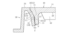
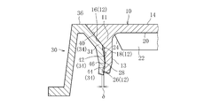
- FIG. 2 is a longitudinal cross-sectional view of the main part of the underground structure lid according to Embodiment 1 of the present invention.
- the inner peripheral surface 34 formed on the inner peripheral portion 31 of the receiving frame 30 is constituted by a receiving frame first surface portion 40 continuous with the upper surface 36 of the receiving frame 30 and a receiving frame second surface portion 42 below the receiving frame first surface portion 40. .
- the receiving frame first surface portion 40 is formed with a reduced diameter toward the lower side of the receiving frame 30 with a gentle gradient.
- the gentle gradient of the receiving frame first surface portion 40 means a range in which the angle with respect to the vertical ( ⁇ in FIG. 2) is 25 ° to 45 °. In this embodiment, the gentle gradient ⁇ is formed at 30 °. ing. Note that “slow gradient” or “gradient” used in the following description is defined as an angle with respect to the vertical.
- the gentle gradient ⁇ is set to 25 ° or more.
- the receiving frame second surface portion 42 is formed with a diameter that is reduced toward the lower side of the receiving frame 30 with a steeper slope than the receiving frame first surface portion 40 below the receiving frame first surface portion 40.
- the receiving frame second surface portion 42 has a slope ⁇ in the range of 1 ° to 10 °.
- the receiving frame second surface portion 42 has a gradient ⁇ of 2 °.
- the outer peripheral surface 12 formed on the outer peripheral portion 11 of the lid main body 10 is composed of a lid first surface portion 16 continuous with the upper surface 14 of the lid main body 10 and a lid second surface portion 18 below the lid first surface portion 16. ing.
- the lid first surface portion 16 is formed with a reduced diameter toward the lower side of the lid body 10 with a gentle gradient. Specifically, the lid first surface portion 16 has substantially the same gentle gradient as the receiving frame first surface portion 40. In this embodiment, the lid first surface portion 16 reduces the gentle gradient of the receiving frame first surface portion 40. It is formed at the same 30 ° as ⁇ .
- the lid second surface portion 18 is formed by reducing the diameter toward the lower side of the lid body 10 with a steeper slope than the receiving frame second surface portion 42 below the lid first surface portion 16. Specifically, the lid second surface portion 18 has a gradient ⁇ in the range of 0 ° to 9 °. In the present embodiment, the lid second surface portion 18 has a gradient ⁇ of 1 °.
- elastic deformation used in the following description is defined as a concept including plastic deformation in a state where a pressing force due to elastic deformation remains.
- the outer peripheral portion 11 of the lid body 10 is greatly deformed so as to be reduced in diameter from the state indicated by the broken line in the radial direction indicated by the solid line.
- the inner peripheral portion 31 of the receiving frame 30 is also elastically deformed.
- the inner peripheral portion 31 is slightly smaller than the elastic deformation of the outer peripheral portion 11 of the lid body 10, so FIG.
- the elastic deformation of the inner peripheral portion 31 of the receiving frame 30 is omitted. The same applies to any of the following embodiments.
- the lid first surface portion 16 is supported by the receiving frame first surface portion 40, whereby the weight applied to the lid main body 10 and the vehicle or the like traveling on the lid main body 10 are subjected to the receiving frame. It is supported by the first surface portion 40. Furthermore, the lower part of the lid second surface part 18 and the lower part of the receiving frame second surface part 42 come into contact with each other, and due to the pressing force due to the elastic deformation of the outer peripheral part 11 of the lid main body 10, the lid second surface part 18 and the receiving frame second surface part 42. Are pressed against each other.
- the pressing force in this case is a restoring force generated when the outer peripheral portion 11 of the lid main body 10 is elastically deformed by the deflection amount ⁇ from the natural state of FIG. 2, and is from the lid second surface portion 18 to the receiving frame second surface portion 42.
- the action part P acts in the diameter increasing direction of the lid body 10.
- the pressing force due to the elastic deformation of the outer peripheral portion 11 of the lid body 10 acts, so that when the lid body 10 tries to move in the vertical direction, the lid second surface portion 18 and the receiving frame first A frictional force is generated between the two surface portions 42 and the movement of the lid body 10 in the vertical direction is suppressed. Therefore, it is possible to prevent an excessive biting force from being generated on the receiving frame 30 of the lid main body 10 by the gentle-gradient receiving frame first surface portion 40 and the gentle-gradient lid first surface portion 16. Furthermore, rattling, vibration, noise, and sliding of the lid main body 10 can be suppressed by the pressing force and frictional force generated between the outer peripheral portion 11 of the lid main body 10 and the inner peripheral portion 31 of the receiving frame 30. .
- the inherent elastic coefficient of the outer peripheral portion 11 of the lid main body 10 and the sectional modulus of the outer peripheral portion 11 of the lid main body 10, and the intrinsic elastic coefficient of the inner peripheral portion 31 of the receiving frame 30 and the inner periphery of the receiving frame 30 are described.
- the section modulus of the portion 31 the outer peripheral portion 11 of the lid body 10 is greatly elastically deformed.
- the present invention is not limited to this, and setting the inner peripheral portion 31 of the receiving frame 30 to be elastically deformed greatly also causes both the outer peripheral portion 11 of the lid body 10 and the inner peripheral portion 31 of the receiving frame 30 to be elastically deformed appropriately. Can also be set.
- an annular gap G1 is formed between the lid second surface portion 18 and the receiving frame second surface portion 42, and the lower portion of the lid second surface portion 18 and the receiving frame second surface portion 42 are formed.
- the bottom is in contact with the bottom.
- the present invention is not limited to this, and the elastic modulus of the outer peripheral portion 11 of the lid main body 10 and the inner peripheral portion 31 of the receiving frame 30, the diameter size and the angle of the outer peripheral surface 12 of the lid main body 10 and the inner peripheral surface 34 of the receiving frame 30 are set.
- the contact state between the lid second surface portion 18 and the receiving frame second surface portion 42 can be controlled.
- the lid second surface portion 18 and the receiving frame second surface portion 42 are in contact with each other, and the annular gap G1 is not formed. There may be cases.
- lattice-shaped reinforcing ribs 22 are disposed on the back surface 20 of the lid body 10 of this embodiment.
- the end 24 of the reinforcing rib 22 is separated from the inner peripheral wall 13 of the outer peripheral portion 11 of the lid main body 10 so that the elastic deformation of the outer peripheral portion 11 of the lid main body 10 is not hindered when the lid main body 10 is placed in the receiving frame 30. It is preferable.
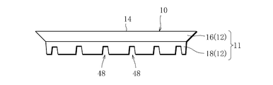
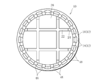
- a plurality of notches 48 are arranged in the outer peripheral portion 11 of the lid main body 10 of the present embodiment in a slit shape in the circumferential direction, for example, on the lid second surface portion 18 at substantially equal intervals. .
- the rigidity of the outer peripheral portion 11 of the lid main body 10 is lowered, so that the outer peripheral portion 11 of the lid main body 10 is further elastically deformed. It can be promoted and is suitable.
- the plurality of cutout portions 48 are formed in the outer peripheral portion 11 of the lid body 10 in a slit shape, but the present invention is not limited thereto, and the plurality of cutout portions 48 are formed in the inner peripheral portion 31 of the receiving frame 30.
- the receiving frame second surface portion 42 may be formed by notching in a slit shape at substantially equal intervals in the circumferential direction. In this case, the elastic deformation of the inner peripheral portion 31 of the receiving frame 30 can be further promoted.
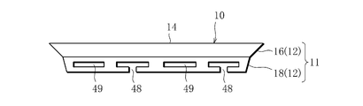
- the shape of the notch is not limited to the slit shape, and may be a substantially T-shaped notch 48 as shown in FIG.
- the through-hole portion 49 may be used instead of the notched portion 48.
- FIG. A part thereof is a through-hole portion 49 having a window frame shape.
- the receiving frame second surface portion 42 is continuously formed below the receiving frame first surface portion 40, and the lid second surface portion 18 is continuously formed below the lid first surface portion 16.
- an R curved surface portion 41 is formed between the receiving frame first surface portion 40 and the receiving frame second surface portion 42, or the lid first surface portion 16 and the lid second surface portion 18
- the receiving frame first surface portion 40 and the receiving frame second surface portion 42, and the lid first surface portion 16 and the lid second surface portion 18 may be formed discontinuously, such as forming the R curved surface portion 17 and the step portion therebetween.
- a stepped portion or an inclined surface may be formed instead of the R curved surface portion (41, 17).
- FIG. 8 is a longitudinal cross-sectional view of the main part of the underground structure lid according to Embodiment 2 of the present invention.
- the inner peripheral surface 34 formed on the inner peripheral portion 31 of the receiving frame 30 of the present embodiment includes a receiving frame first surface portion 40 continuous with the upper surface 36 of the receiving frame 30, a receiving frame second surface portion 42 below the receiving frame first surface portion 40, and Further, it is composed of a receiving frame third surface portion 66 below the receiving frame second surface portion 42.
- the receiving frame second surface portion 42 is formed with a diameter that is reduced toward the lower side of the receiving frame 30 with a steeper slope than the receiving frame first surface portion 40 below the receiving frame first surface portion 40.
- the receiving frame third surface portion 66 is formed to have a diameter that is reduced toward the lower side of the receiving frame 30 with a different gradient from the receiving frame second surface portion 42 below the receiving frame second surface portion 42.
- the receiving frame second surface portion 42 has a slope ⁇ in the range of 1 ° to 10 °
- the receiving frame third surface portion 66 has the same orientation as the receiving frame second surface portion 42 but a different gradient ⁇ 1 from 0 °. Largely formed.
- the receiving frame second surface portion 42 is formed with a gradient ⁇ of 8 °
- the receiving frame third surface portion 66 is formed with a gradient ⁇ 1 of 6 ° that is steeper than the receiving frame second surface portion 42.
- the outer peripheral surface 12 formed on the outer peripheral portion 11 of the lid main body 10 includes a lid first surface portion 16 continuous with the upper surface 14 of the lid main body 10, a lid second surface portion 18 below the lid first surface portion 16, and a lid. It is composed of a lid third surface portion 68 below the second surface portion 18.
- the lid second surface portion 18 is formed by reducing the diameter toward the lower side of the lid body 10 with a steeper slope than the receiving frame second surface portion 42 below the lid first surface portion 16.
- the lid third surface portion 68 is formed below the lid second surface portion 18 by reducing its diameter toward the bottom of the lid body 10 with the same orientation as the lid second surface portion 18 but with a different gradient.
- the lid second surface portion 18 has a slope ⁇ of 0 ° to 9 °
- the lid third surface portion 68 has a slope ⁇ 1 larger than 0 °.
- the lid second surface portion 18 is formed with a gradient ⁇ of 3 °
- the lid third surface portion 68 is formed with a gradient ⁇ 1 of 6 ° that is a gentler gradient than the lid second surface portion 18.
- the lid third surface portion 68 and the receiving frame second surface portion 42 first start contact, and then the lid third surface portion 68 and the receiving frame third surface portion 66. Begins to abut. Further, when the lid main body 10 is placed in the receiving frame 30 and the closed state shown in FIG. 9 is reached, at least one of the outer peripheral portion 11 of the lid main body 10 and the inner peripheral portion 31 of the receiving frame 30 is elastically deformed, and the lid main body 10 is received by the receiving frame. Fits in 30 regular lid positions.
- the lid first surface portion 16 is supported by the receiving frame first surface portion 40, whereby the weight of the lid main body 10 and the load applied when the vehicle or the like travels on the lid main body 10 receives the receiving frame. It is supported by the first surface portion 40. Furthermore, a substantially intermediate position in the vertical direction of the lid third surface portion 68 and the upper portion of the receiving frame third surface portion 66 abut, and the pressing force due to elastic deformation of the outer peripheral portion 11 of the lid body 10 causes the lid third surface portion 68 and the receiving frame. The third surface portion 66 is pressed against each other.
- the pressing force in this case is a restoring force generated when the outer peripheral portion 11 of the lid body 10 is elastically deformed by the deflection amount ⁇ from the natural state of FIG. 8, and from the lid third surface portion 68 to the receiving frame third surface portion 66.
- the action part P acts in the diameter increasing direction of the lid body 10.
- the radial movement of the lid main body 10 is suppressed by the pressing force due to the elastic deformation of the outer peripheral portion 11 of the lid main body 10, and between the lid third surface portion 68 and the receiving frame third surface portion 66 in the closed state.
- a frictional force is generated, and the movement of the lid body 10 in the vertical direction is suppressed. Therefore, it is possible to prevent an excessive biting force from being generated on the receiving frame 30 of the lid body 10.
- rattling, vibration, noise, and sliding of the lid main body 10 can be suppressed by the pressing force and frictional force generated between the outer peripheral portion 11 of the lid main body 10 and the inner peripheral portion 31 of the receiving frame 30. .
- an annular gap G2 is formed between the lid second surface portion 18 and the lid third surface portion 68 and the receiving frame second surface portion 42, and the lid third surface portion 68 and the receiving frame first shape are formed.
- the three surface portions 66 are in contact with each other.
- the present invention is not limited to this, and the elastic modulus of the outer peripheral portion 11 of the lid body 10 and the inner peripheral portion 31 of the receiving frame 30, the outer peripheral surface 12 of the outer peripheral portion 11 of the lid main body 10, and the inner peripheral surface of the inner peripheral portion 31 of the receiving frame 30.
- the contact state between the lid third surface portion 68 and the receiving frame third surface portion 66 can be controlled by setting the diameter dimension and the angle 34.
- At least one of the lid second surface portion 18 and the lid third surface portion 68 may be at least in contact with at least one of the receiving frame second surface portion 42 and the receiving frame third surface portion 66. Further, due to the elastic deformation of the outer peripheral portion 11 of the lid main body 10 and the inner peripheral portion 31 of the receiving frame 30, the lid second surface portion 18 and the lid third surface portion 68, the receiving frame second surface portion 42, and the receiving frame third surface portion 66 are almost entirely covered. There may be a case where the annular gap G2 is not formed.
- the receiving frame second surface portion 42 and the receiving frame third surface portion 66 are successively formed below the receiving frame first surface portion 40 in order, and the lid second surface portion 18 and the lid are formed below the lid first surface portion 16.
- the 3rd surface part 68 is formed continuously in order.
- the receiving frame first surface portion 40 and the receiving frame second surface portion 42, the receiving frame second surface portion 42 and the receiving frame third surface portion 66 may be formed discontinuously.
- the lid first surface portion 16 and the lid second surface portion 18, and the lid second surface portion 18 and the lid third surface portion 68 may be formed discontinuously.
- FIG. 10 is a vertical cross-sectional view of the main part of the underground structure lid according to Embodiment 3 of the present invention.
- the inner peripheral surface 34 formed on the inner peripheral portion 31 of the receiving frame 30 of the present embodiment includes a receiving frame first surface portion 40 continuous with the upper surface 36 of the receiving frame 30, a receiving frame second surface portion 42 below the receiving frame first surface portion 40, and Further, it is composed of a receiving frame fourth surface portion 44 below the receiving frame second surface portion 42.
- the receiving frame fourth surface portion 44 is formed below the receiving frame second surface portion 42 so as to increase in diameter toward the lower side of the receiving frame 30 with a gradient. Specifically, the receiving frame fourth surface portion 44 forms a gradient ⁇ opposite to the receiving frame second surface portion 42 in the range of 0 ° to 9 °. In this embodiment, the receiving frame fourth surface portion 44 is formed with a gradient ⁇ of 4 °.
- the outer peripheral surface 12 formed on the outer peripheral portion 11 of the lid main body 10 is continuous with the upper surface 14 of the lid main body 10, the lid first surface portion 16, the lid second surface portion 18 below the lid first surface portion 16, and It is composed of a lid fourth surface portion 26 below the lid second surface portion 18.
- the lid fourth surface portion 26 is formed below the lid second surface portion 18 so as to increase in diameter toward the bottom of the lid body 10 with a gradient. Specifically, the lid fourth surface portion 26 forms a gradient ⁇ opposite to the lid second surface portion 18 in the range of 0 ° to 10 °. In the present embodiment, the lid fourth surface portion 26 has a slope ⁇ of 5 °. As shown in FIG. 11, when the lid main body 10 is placed in the receiving frame 30, the lower part of the lid fourth surface portion 26 and the receiving frame second surface portion 42 start to contact each other. When the lid body 10 is further housed in the receiving frame 30, at least one of the outer peripheral portion 11 of the lid main body 10 and the inner peripheral portion 31 of the receiving frame 30 is elastically deformed. In the case of the present embodiment, as shown in FIG. 11, the outer peripheral portion 11 of the lid body 10 is greatly elastically deformed so as to be reduced in diameter from the natural state indicated by the broken line in the radial direction indicated by the solid line.
- the lid fourth surface portion 26 gets over the boundary 46 between the receiving frame second surface portion 42 and the receiving frame fourth surface portion 44, and the lid second surface portion 18 and the lid fourth surface.
- the boundary 28 with the surface portion 26 substantially coincides with the boundary 46, and the lid body 10 is in the normal lid position of the receiving frame 30.
- the lid first surface portion 16 is supported by the receiving frame first surface portion 40, whereby the weight of the lid main body 10 and a load applied by the vehicle or the like traveling on the lid main body 10 are applied to the receiving frame first surface portion 40. Supported. Further, the lid fourth surface portion 26 and the receiving frame fourth surface portion 44 are in contact with each other over the entire circumference, and the lid fourth surface portion 26 and the receiving frame fourth surface portion are pressed by the pressing force due to the elastic deformation of the outer peripheral portion 11 of the lid body 10. 44 are pressed against each other. Furthermore, the outer peripheral part 11 of the lid body 10 is restrained from the inner peripheral part 31 of the receiving frame 30 in a state of being prevented from coming off by pressing the enlarged fourth lid surface part 26 and the fourth receiving frame part 44.
- the pressing force in this case is a restoring force generated when the outer peripheral portion 11 of the lid main body 10 is elastically deformed by the deflection amount ⁇ from the natural state of FIG. 10, and from the lid fourth surface portion 26 to the receiving frame fourth surface portion 44.
- the lid body 10 acts in the diameter increasing direction.
- the lid fourth surface portion 26 and the receiving frame fourth surface portion 44 are pressed against each other by the pressing force generated by the elastic deformation of the outer peripheral portion 11 of the lid body 10, thereby suppressing the radial movement of the lid body 10.
- the pressing force due to the elastic deformation of the outer peripheral portion 11 of the lid body 10 acts, so when the lid body 10 tries to move in the vertical direction, the lid fourth surface portion 26 and the receiving frame first A frictional force is generated between the four surface portions 44 and the movement of the lid body 10 in the vertical direction is suppressed. Therefore, it is possible to prevent an excessive biting force from being generated on the receiving frame 30 of the lid main body 10 by the gentle-gradient receiving frame first surface portion 40 and the gentle-gradient lid first surface portion 16. Furthermore, rattling, vibration, noise, and sliding of the lid main body 10 can be suppressed by the pressing force and frictional force generated between the outer peripheral portion 11 of the lid main body 10 and the inner peripheral portion 31 of the receiving frame 30. .
- the lid fourth surface portion 26 and the receiving frame fourth surface portion 44 are pressed against each other by the pressing force due to the elastic deformation of the outer peripheral portion 11 of the lid body 10. Furthermore, the outer peripheral part 11 of the lid body 10 is restrained from the inner peripheral part 31 of the receiving frame 30 in a state of being prevented from coming off by pressing the enlarged fourth lid surface part 26 and the fourth receiving frame part 44. For this reason, it is preferable that the vertical movement of the lid body 10 can be more effectively suppressed by the restraint by the pressing force, the frictional force, and the retaining prevention as compared with the case of the first and second embodiments.
- the inherent elastic coefficient of the outer peripheral portion 11 of the lid main body 10, the section coefficient of the outer peripheral portion 11 of the lid main body 10, and the inner periphery of the receiving frame 30 is largely elastically deformed by setting the inherent elastic coefficient of the part 31 and the section modulus of the inner peripheral part 31 of the receiving frame 30.
- the present invention is not limited to this, and setting the inner peripheral portion 31 of the receiving frame 30 to be elastically deformed greatly also causes both the outer peripheral portion 11 of the lid body 10 and the inner peripheral portion 31 of the receiving frame 30 to be elastically deformed appropriately. Can also be set.
- FIG. 13 is a longitudinal cross-sectional view of the principal part of the lid
- symbol is attached
- the inner peripheral surface 34 formed on the inner peripheral portion 31 of the receiving frame 30 of the present embodiment includes a receiving frame first surface portion 40 that is continuous with the upper surface 36 of the receiving frame 30, and the receiving frame first surface portion 40.
- the lower receiving frame second surface portion 42 and a receiving frame fourth surface portion 44 below the receiving frame second surface portion 42 are configured.
- the outer peripheral surface 12 formed on the outer peripheral portion 11 of the lid main body 10 includes a lid first surface portion 16 continuous with the upper surface 14 of the lid main body 10, a lid second surface portion 18 below the lid first surface portion 16, and a lid.
- the cover 4 comprises a lid fourth surface portion 26 below the second surface portion 18 and a lid fifth surface portion 50 below the lid fourth surface portion 26.
- the lid fifth surface portion 50 is formed below the lid fourth surface portion 26 so as to be reduced in diameter toward the bottom of the lid body 10 with a gradient.
- the lid fifth surface portion 50 is formed with a gradient having an angle equal to that of the receiving frame second surface portion 42.
- the lid fifth surface portion 50 and the receiving frame second surface portion 42 start abutting, and when the lid main body 10 is further stored in the receiving frame 30, At least one of the outer peripheral portion 11 and the inner peripheral portion 31 of the receiving frame 30 is elastically deformed.
- the outer peripheral portion 11 of the lid body 10 is greatly elastically deformed so as to be reduced in diameter from the natural state indicated by the broken line in the radial direction indicated by the solid line.
- the lid fourth surface portion 26 and the lid fifth surface portion 50 get over the boundary 46 between the receiving frame second surface portion 42 and the receiving frame fourth surface portion 44 from the state of FIG.
- the boundary 28 between the surface portion 18 and the lid fourth surface portion 26 is substantially coincident with the boundary 46, and the lid body 10 is placed in the normal lid position of the receiving frame 30.
- the lid first surface portion 16 is supported by the receiving frame first surface portion 40, so that the weight of the lid body 10 and the vehicle travel on the lid body 10.
- the applied load is supported by the receiving frame first surface portion 40.
- the lid fourth surface portion 26 and the receiving frame fourth surface portion 44 are in contact with each other over the entire circumference, and the lid fourth surface portion 26 and the receiving frame fourth surface portion are pressed by the pressing force due to the elastic deformation of the outer peripheral portion 11 of the lid body 10. 44 are pressed against each other.
- the outer peripheral part 11 of the lid body 10 is restrained from the inner peripheral part 31 of the receiving frame 30 in a state of being prevented from coming off by pressing the enlarged fourth lid surface part 26 and the fourth receiving frame part 44.
- the pressing force in this case is a restoring force generated as the outer peripheral portion 11 of the lid main body 10 is elastically deformed by the deflection amount ⁇ from the natural state of FIG. It acts in the diameter-expanding direction of the lid body 10 from the four surface portions 26 to the receiving frame fourth surface portion 44.
- the lid fifth surface portion 50 is formed with a gradient having an angle equal to that of the receiving frame second surface portion 42, so that when the lid main body 10 is placed in the receiving frame 30, FIG.
- the receiving frame second surface portion 42 can function as a guide surface for the lid fifth surface portion 50, so that the lid body 10 can be smoothly closed, and the operator can close the lid.
- the burden can be greatly reduced.
- FIG. 16 is a longitudinal cross-sectional view of the principal part of the lid
- the inner peripheral surface 34 formed on the inner peripheral portion 31 of the receiving frame 30 of the present embodiment is similar to the first embodiment in that the receiving frame first surface portion 40 that is continuous with the upper surface 36 of the receiving frame 30 and the receiving frame first surface portion 40.
- the lower receiving frame second surface portion 42 is configured.
- the outer peripheral surface 12 formed on the outer peripheral portion 11 of the lid main body 10 is composed of a lid first surface portion 16 continuous with the upper surface 14 of the lid main body 10 and a lid second surface portion 18 below the lid first surface portion 16. ing.
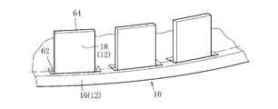
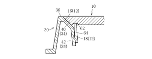
- the cover 2nd surface part 18 is formed in the downward direction of the cover 1st surface part by the protrusion part 64 made to protrude in the circumferential direction at intervals. Further, as shown in FIGS. 16 and 17, a recess 62 is provided at the base end of the protrusion 64 so as to surround the protrusion 64.
- the lid first surface portion 16 is supported by the receiving frame first surface portion 40, so that the weight of the lid body 10, the vehicle, etc.
- the load applied by traveling is supported by the receiving frame first surface portion 40.
- the lower part of the lid second surface part 18 and the lower part of the receiving frame second surface part 42 come into contact with each other, and the lid second surface part 18 causes the receiving frame second surface part 42 to be pressed by the pressing force due to the elastic deformation of the outer peripheral part 11 of the lid body 10. Press.
- the base end of the protrusion 64 is provided with the recess 62 so as to surround the protrusion 64. For this reason, it becomes possible to ensure the height of the protrusion 64 high while keeping the height of the lid body (the height from the upper surface 14 of the lid body 10 to the lower end of the protrusion 64) at a predetermined height. It is preferable because the elastic deformation of the portion 64 can be promoted.
- the lid second surface portion 18 is formed by the protruding portion 64, but the present invention is not limited thereto, and the receiving frame second surface portion 42 may be formed by the protruding portion.
- the present invention is not limited to the above embodiments, and various modifications are possible.
- the shapes of the lid body 10 and the receiving frame 30 are not limited to the above-described embodiments, and can be used for a square underground structure as long as the pressing force and the frictional force accompanying the elastic deformation of each part described above can be generated.
- various other modifications such as a lid can be considered.
Abstract
Description
なお、本願明細書でいう「地下構造物用蓋」とは、下水道における地下埋設物,地下構造施設等と地上とを通じる開口部を開閉可能に閉塞するマンホール蓋,大型鉄蓋,汚水桝蓋、電力・通信における地下施設機器や地下ケーブル等を保護する開閉可能な共同溝用鉄蓋,送電用鉄蓋,配電用鉄蓋、上水道やガス配管における路面下の埋設導管およびその付属機器と地上とを結ぶ開閉扉としての機能を有する消火栓蓋,制水弁蓋,仕切弁蓋,空気弁蓋,ガス配管用蓋,量水器蓋等を総称する。
これに対し、勾配受構造の地下構造物用蓋として、特許文献1には、蓋本体の外周部の勾配面および受枠の内周部の勾配面の鉛直に対する傾斜角度を5°~10°に限定するとともに、蓋本体の外周部の勾配面の高さを受枠の内周部の勾配面の高さよりも小さくしたものが記載されている。特許文献1に記載のものでは、上記のように勾配面の角度を限定することにより、蓋本体の受枠に対する食い込み力を充分確保させることができ、蓋本体のがたつき、振動、騒音を著しく抑えることができるとともに、蓋本体のずり上がりも殆ど起こさないという効果を奏することができる。
そこで、本発明が解決しようとする課題は、蓋本体のがたつき、振動、騒音を抑えることができるとともに、蓋本体の受枠への過剰な食い込み力が発生することを防止して適度な労力で開蓋を行うことができ、受枠に対する蓋本体のずり上がりも防止することができる地下構造物用蓋を提供することにある。
好ましくは、最初に蓋本体を受枠に納めて閉蓋状態とするとき、蓋本体の外周部の外周面または下面と、受枠の内周部の内周面とが当接することにより、蓋本体の外周部および/または受枠の内周部が、弾性変形による押圧力が残る状態で塑性変形する。
好ましくは、複数の切欠部および/または複数の貫通孔部は、蓋第2面部から下方に位置する蓋本体の外周部および/または受枠第2面部から下方に位置する受枠の内周部に設けている。
好ましくは、突出部の基端には、突出部を囲むように凹部が設けられている。
好ましくは、蓋本体の裏面に補強リブを有し、補強リブの端部は、蓋本体の外周部の内周壁と離間している。
具体的には、蓋第2面部と受枠第2面部とが、または蓋第2面部および蓋第3面部の少なくとも何れか一方と受枠第2面部および受枠第3面部の少なくとも何れか一方とが、または蓋第4面部と受枠第4面部とが、蓋本体の外周部および受枠の内周部の少なくとも何れか一方の弾性変形による押圧力で互いに押圧され、これにより蓋本体の径方向の動きが抑制される。さらには、蓋本体が上下方向へ動こうとする際に、押圧力により、蓋第2面部と受枠第2面部の間に、または蓋第2面部および蓋第3面部の少なくとも何れか一方と受枠第2面部および受枠第3面部の少なくとも何れか一方との間に、または蓋第4面部と受枠第4面部との間に、摩擦力が生じ、蓋本体の上下方向への動きも抑制される。したがって、蓋本体の受枠への過剰な食い込み力が発生することを防止できるとともに、蓋本体の外周部と受枠の内周部との間に発生する押圧力および摩擦力によって、蓋本体のがたつき、振動、騒音、ずり上がりを抑えることができる。
図1に示すように、本発明に係る地下構造物用蓋は、蓋本体10と、この蓋本体10を内周部で開閉可能に支持する受枠30とを備え、蓋本体10と受枠30とは図示しない蝶番金物によって連結されている。この地下構造物用蓋は、球状黒鉛鋳鉄により形成されており、例えばマンホールの上部側塊の上端部に基礎調整部を介して取り付けられ、蓋本体10の上面14が地表面と面一となるように設置される。
<実施例1>
受枠第1面部40は、緩勾配をもって受枠30の下方に向けて縮径して形成している。具体的に受枠第1面部40の緩勾配とは、鉛直を基準とした角度(図2のα)が25°~45°の範囲をいい、本実施例では緩勾配αを30°で形成している。なお、以降の説明で使用する「緩勾配」または「勾配」は、すべて鉛直を基準とした角度として定義する。
一方、蓋本体10の外周部11に形成した外周面12は、蓋本体10の上面14に連続した蓋第1面部16と、蓋第1面部16の下方の蓋第2面部18とから構成している。
蓋第2面部18は、蓋第1面部16の下方において受枠第2面部42よりも急な勾配をもって蓋本体10の下方に向けて縮径して形成している。具体的には、蓋第2面部18はその勾配γを0°~9°の範囲に形成している。なお、本実施例において蓋第2面部18は勾配γを1°で形成している。
以上のように本実施例では、蓋本体10の閉蓋状態において、緩勾配の受枠第1面部40において蓋本体10の自重および車輌等が蓋本体10上を走行することによって加わる荷重が支持され、蓋本体10の受枠30への過剰な食い込み力が発生することを防止できる。さらには、蓋本体10の外周部11の弾性変形による押圧力により、蓋第2面部18と受枠第2面部42とが互いに押圧されることにより蓋本体10の径方向の動きが抑制される。
図4に示すように本実施例の蓋本体10の外周部11には、その周方向に、例えば蓋第2面部18に複数の切欠部48を略等間隔にスリット状に配設している。蓋本体10の外周部11に複数の切欠部48をスリット状に配設することにより、蓋本体10の外周部11の剛性が低下するため、蓋本体10の外周部11の弾性変形をより一層促進させることができて好適である。
また、切欠部の形状はスリット状に限らず、図6に示すように略T字状の切欠部48としても良い。なお、蓋本体10の外周部11や受枠30の内周部31の弾性変形をより一層促進させる上では、切欠部48ではなく、貫通孔部49としてもよく、図6では、切欠部48の一部を、窓枠状の貫通孔部49としている。
<実施例2>
本実施例の受枠30の内周部31に形成した内周面34は、受枠30の上面36に連続した受枠第1面部40と、受枠第1面部40の下方の受枠第2面部42と、さらに受枠第2面部42の下方の受枠第3面部66とから構成している。
蓋第2面部18は、蓋第1面部16の下方において受枠第2面部42よりも急な勾配をもって蓋本体10の下方に向けて縮径して形成している。また、蓋第3面部68は、蓋第2面部18の下方において、蓋第2面部18と同じ向きだが異なる勾配をもって蓋本体10の下方に向けて縮径して形成している。具体的には、蓋第2面部18はその勾配γを0°~9°の範囲で形成し、蓋第3面部68はその勾配γ1を0°より大きく形成している。なお、本実施例において、蓋第2面部18は勾配γを3°で形成し、蓋第3面部68は勾配γ1を蓋第2面部18よりも緩勾配となる6°で形成している。
以上のように本実施例では、実施例1の場合と同様に、蓋本体10の閉蓋状態において、緩勾配の受枠第1面部40において蓋本体10の自重および車輌等が蓋本体10上を走行することによって加わる荷重が支持され、蓋本体10の受枠30への過剰な食い込み力が発生することを防止できる。さらには、蓋本体10の外周部11の弾性変形による押圧力により、蓋本体10の径方向の動きが抑制され、また、閉蓋状態において蓋第3面部68と受枠第3面部66との間に摩擦力が生じ、蓋本体10の上下方向への動きが抑制される。したがって、蓋本体10の受枠30への過剰な食い込み力が発生することを防止することができる。さらには、蓋本体10の外周部11と受枠30の内周部31との間に発生する押圧力および摩擦力によって、蓋本体10のがたつき、振動、騒音、ずり上がりを抑えることができる。
<実施例3>
本実施例の受枠30の内周部31に形成した内周面34は、受枠30の上面36に連続した受枠第1面部40と、受枠第1面部40の下方の受枠第2面部42と、さらに受枠第2面部42の下方の受枠第4面部44とから構成している。
一方、蓋本体10の外周部11に形成した外周面12は、蓋本体10の上面14に連続した、蓋第1面部16と、蓋第1面部16の下方の蓋第2面部18と、さらに蓋第2面部18の下方の蓋第4面部26とから構成している。
図11に示すように、蓋本体10を受枠30に納める際に、蓋第4面部26の下方と受枠第2面部42とが当接を開始する。さらに蓋本体10を受枠30に納めると、蓋本体10の外周部11および受枠30の内周部31の少なくとも何れか一方が弾性変形する。なお、本実施例の場合、図11に示すように蓋本体10の外周部11が破線で示す自然状態から実線で示す径方向に縮径されるようにして大きく弾性変形している。
以上のように本実施例では、実施例1および実施例2の場合と同様に、蓋本体10の閉蓋状態において、緩勾配の受枠第1面部40において蓋本体10の自重および車輌等が蓋本体10上を走行することによって加わる荷重が支持され、蓋本体10の受枠30への過剰な食い込み力が発生することを防止できる。さらには、蓋本体10の外周部11の弾性変形による押圧力により、蓋第4面部26と受枠第4面部44とが互いに押圧されることにより蓋本体10の径方向の動きが抑制される。
<実施例4>
本実施例の受枠30の内周部31に形成した内周面34は、実施例3の場合と同様に、受枠30の上面36に連続した受枠第1面部40と、受枠第1面部40の下方の受枠第2面部42と、さらに受枠第2面部42の下方の受枠第4面部44とから構成している。
蓋第5面部50は、蓋第4面部26の下方において、勾配をもって蓋本体10の下方に向けて縮径して形成している。なお、本実施例では、蓋第5面部50を受枠第2面部42と等しい角度の勾配をもって形成している。
以上のように本実施例の場合には、蓋第5面部50を受枠第2面部42と等しい角度の勾配をもって形成したことにより、蓋本体10を受枠30に納めるとき、実施例3の図11に示す場合に比べて、受枠第2面部42を蓋第5面部50のガイド面として機能させることができるため、蓋本体10を円滑に閉蓋することが可能となり、作業者の閉蓋作業の負担を大幅に軽減することができる。
<実施例5>
本実施例の受枠30の内周部31に形成した内周面34は、実施例1の場合と同様に、受枠30の上面36に連続した受枠第1面部40と、受枠第1面部40の下方の受枠第2面部42とから構成している。
蓋第2面部18は、蓋第1面部の下方において、周方向に間隔をあけて複数突出させた突出部64により形成している。また、突出部64の基端には、図16および図17に示すように、突出部64を囲むように凹部62が設けられている。
なお、本実施例では、蓋第2面部18を突出部64により形成しているが、これに限らず、受枠第2面部42を突出部により形成する場合も有り得る。
例えば、蓋本体10および受枠30の形状は上記各実施例に限定されるものではなく、前記した各部の弾性変形に伴う押圧力および摩擦力を発生可能であれば、角型の地下構造物用蓋など、他にも種々の変形が考えられるのは勿論である。
16 蓋第1面部
18 蓋第2面部
20 裏面
22 補強リブ
24 端部
26 蓋第4面部
30 受枠
40 受枠第1面部
42 受枠第2面部
44 受枠第4面部
48 スリット(切欠部)
50 蓋第5面部
66 受枠第3面部
68 蓋第3面部
Claims (10)
- 蓋本体と、前記蓋本体を内周部で開閉可能に支持する受枠とを備えた地下構造物用蓋であって、
前記受枠の内周部は、
緩勾配をもって前記受枠の下方に向けて縮径して形成される受枠第1面部と、
前記受枠第1面部の下方において前記受枠第1面部よりも急な勾配をもって前記受枠の下方に向けて縮径して形成される受枠第2面部とを有し、
前記蓋本体の外周部は、
緩勾配をもって前記蓋本体の下方に向けて縮径して形成される蓋第1面部と、
前記蓋第1面部の下方において、前記蓋本体の下方に向けて鉛直に、または前記受枠第2面部よりも急な勾配をもって前記蓋本体の下方に向けて縮径して、形成される蓋第2面部とを有し、
前記蓋本体の閉蓋状態において、前記蓋第1面部が前記受枠第1面部に支持されるとともに、前記蓋第2面部と前記受枠第2面部とが前記蓋本体の外周部および前記受枠の内周部の少なくとも何れか一方の弾性変形による押圧力により互いに押圧されることを特徴とする地下構造物用蓋。 - 蓋本体と、前記蓋本体を内周部で開閉可能に支持する受枠とを備えた地下構造物用蓋であって、
前記受枠の内周部は、
緩勾配をもって前記受枠の下方に向けて縮径して形成される受枠第1面部と、
前記受枠第1面部の下方において前記受枠第1面部よりも急な勾配をもって前記受枠の下方に向けて縮径して形成される受枠第2面部と、
前記受枠第2面部の下方において前記受枠第2面部と異なる勾配をもって前記受枠の下方に向けて縮径して形成される受枠第3面部とを有し、
前記蓋本体の外周部は、
緩勾配をもって前記蓋本体の下方に向けて縮径して形成される蓋第1面部と、
前記蓋第1面部の下方において、前記蓋本体の下方に向けて鉛直に、または前記受枠第2面部よりも急な勾配をもって前記蓋本体の下方に向けて縮径して、形成される蓋第2面部と、
前記蓋第2面部の下方において前記蓋第2面部と異なる勾配をもって前記蓋本体の下方に向けて縮径して形成される蓋第3面部とを有し、
前記蓋本体の閉蓋状態において、前記蓋第1面部が前記受枠第1面部に支持されるとともに、前記蓋第2面部および前記蓋第3面部の少なくとも何れか一方と、前記受枠第2面部および前記受枠第3面部の少なくとも何れか一方とが前記蓋本体の外周部および前記受枠の内周部の少なくとも何れか一方の弾性変形による押圧力により互いに押圧されることを特徴とする地下構造物用蓋。 - 蓋本体と、前記蓋本体を内周部で開閉可能に支持する受枠とを備えた地下構造物用蓋であって、
前記受枠の内周部は、
緩勾配をもって前記受枠の下方に向けて縮径して形成される受枠第1面部と、
前記受枠第1面部の下方に形成される受枠第2面部と、
前記受枠第2面部の下方において、前記受枠の下方に向けて鉛直に、または勾配をもって前記受枠の下方に向けて拡径して、形成される受枠第4面部とを有し、
前記蓋本体の外周部は、
緩勾配をもって前記蓋本体の下方に向けて縮径して形成される蓋第1面部と、
前記蓋第1面部の下方に形成される蓋第2面部と、
前記蓋第2面部の下方において、前記蓋本体の下方に向けて鉛直に、または勾配をもって前記蓋本体の下方に向けて拡径して、形成される蓋第4面部とを有し、
前記蓋本体の閉蓋状態において、前記蓋第1面部が前記受枠第1面部に支持されるとともに、前記蓋第4面部と前記受枠第4面部とが前記蓋本体の外周部および前記受枠の内周部の少なくとも何れか一方の弾性変形による押圧力により互いに押圧されることを特徴とする地下構造物用蓋。 - 前記蓋本体の外周部は、前記蓋第4面部の下方において前記受枠第2面部と等しい角度の勾配をもって前記蓋本体の下方に向けて縮径して形成される蓋第5面部を有することを特徴とする請求項3に記載の地下構造物用蓋。
- 最初に前記蓋本体を前記受枠に納めて閉蓋状態とするとき、前記蓋本体の外周部の外周面または下面と、前記受枠の内周部の内周面とが当接することにより、前記蓋本体の外周部および/または前記受枠の内周部が、弾性変形による押圧力が残る状態で塑性変形することを特徴とする請求項1乃至請求項4のいずれか1項に記載の地下構造物用蓋。
- 前記蓋本体の外周部および/または前記受枠の内周部には、周方向に複数の切欠部および/または複数の貫通孔部を設けたことを特徴とする請求項1乃至請求項5のいずれか1項に記載の地下構造物用蓋。
- 前記複数の切欠部および/または前記複数の貫通孔部は、前記蓋第2面部から下方に位置する前記蓋本体の外周部および/または前記受枠第2面部から下方に位置する前記受枠の内周部に、設けたことを特徴とする請求項6に記載の地下構造物用蓋。
- 前記蓋第2面部から下方に位置する前記蓋本体の外周部および/または前記受枠第2面部から下方に位置する前記受枠の内周部は、周方向に間隔をあけて複数突出させた突出部により形成したことを特徴とする請求項1乃至請求項5のいずれか1項に記載の地下構造物用蓋。
- 前記突出部の基端には、前記突出部を囲むように凹部が設けられていることを特徴とする請求項8に記載の地下構造物用蓋。
- 前記蓋本体の裏面に補強リブを有し、
前記補強リブの端部は、前記蓋本体の外周部の内周壁と離間していることを特徴とする請求項1乃至請求項9のいずれか1項に記載の地下構造物用蓋。
Priority Applications (3)
| Application Number | Priority Date | Filing Date | Title |
|---|---|---|---|
| US14/767,909 US9816247B2 (en) | 2013-02-18 | 2014-02-17 | Lid for underground structure |
| EP14752180.1A EP2957677B1 (en) | 2013-02-18 | 2014-02-17 | Lid for underground structure |
| JP2015500329A JP6324367B2 (ja) | 2013-02-18 | 2014-02-17 | 地下構造物用蓋 |
Applications Claiming Priority (2)
| Application Number | Priority Date | Filing Date | Title |
|---|---|---|---|
| JP2013028955 | 2013-02-18 | ||
| JP2013-028955 | 2013-02-18 |
Publications (1)
| Publication Number | Publication Date |
|---|---|
| WO2014126239A1 true WO2014126239A1 (ja) | 2014-08-21 |
Family
ID=51354237
Family Applications (1)
| Application Number | Title | Priority Date | Filing Date |
|---|---|---|---|
| PCT/JP2014/053636 WO2014126239A1 (ja) | 2013-02-18 | 2014-02-17 | 地下構造物用蓋 |
Country Status (5)
| Country | Link |
|---|---|
| US (1) | US9816247B2 (ja) |
| EP (1) | EP2957677B1 (ja) |
| JP (1) | JP6324367B2 (ja) |
| TW (1) | TWI620853B (ja) |
| WO (1) | WO2014126239A1 (ja) |
Families Citing this family (3)
| Publication number | Priority date | Publication date | Assignee | Title |
|---|---|---|---|---|
| CA3025489C (en) * | 2016-05-27 | 2022-06-21 | EJ USA, Inc. | Skirt for forming an access hatch in concrete |
| US10934667B2 (en) * | 2019-02-21 | 2021-03-02 | Dale KIRK | Hydro-excavation plug |
| CN114134983B (zh) * | 2021-12-07 | 2024-02-09 | 中电建路桥集团有限公司 | 高温多雨地区高速公路沥青道路及其预防性养护方法 |
Citations (8)
| Publication number | Priority date | Publication date | Assignee | Title |
|---|---|---|---|---|
| JPS5372357A (en) | 1976-12-09 | 1978-06-27 | Hinode Suidou Kiki Kk | Circular manhole |
| JPS5973449U (ja) * | 1982-11-05 | 1984-05-18 | 日之出水道機器株式会社 | 丸型蓋構造 |
| JPH08120701A (ja) * | 1994-10-26 | 1996-05-14 | Nagashima Imono Kk | マンホール用蓋受枠 |
| JP2010265599A (ja) * | 2009-05-12 | 2010-11-25 | Tomisu:Kk | 鉄蓋受け枠構造 |
| JP2012021369A (ja) * | 2010-07-16 | 2012-02-02 | Suzuki Chutetsu Kogyo Kk | マンホール蓋用受枠 |
| JP2012057435A (ja) * | 2010-09-13 | 2012-03-22 | Nippon Chutetsukan Kk | 地下構造物用蓋と受枠との嵌合構造 |
| JP3179066U (ja) * | 2012-08-02 | 2012-10-11 | 株式会社荒木製作所 | 地下構造物用蓋装置 |
| JP2013007198A (ja) * | 2011-06-24 | 2013-01-10 | Nippon Chutetsukan Kk | 地下構造物用蓋と受枠との嵌合構造 |
Family Cites Families (14)
| Publication number | Priority date | Publication date | Assignee | Title |
|---|---|---|---|---|
| US2109287A (en) * | 1934-11-09 | 1938-02-22 | Elkington Vivian | Manhole cover and frame |
| AT277090B (de) * | 1968-04-11 | 1969-12-10 | Hawle & Co Kg Flanschen Und Ar | Straßenkappe, insbesondere für Absperrorgane erdverlegter Wasserleitungen od.dgl. |
| US4408421A (en) * | 1981-04-30 | 1983-10-11 | Pai Yang Kuang | Manhole structure |
| GB8702222D0 (en) * | 1987-02-02 | 1987-03-11 | Lighthorne L | Roadway furniture |
| US5165819A (en) * | 1987-07-23 | 1992-11-24 | Bowman Harold M | Manhole cover support with flange borne on its own base |
| US6036401A (en) * | 1998-04-29 | 2000-03-14 | Morina; John | Roadway access device and method of using same |
| TW507799U (en) * | 2001-11-15 | 2002-10-21 | Shian-Fu Gau | Braking device of manhole cover |
| JP3886037B2 (ja) * | 2002-02-14 | 2007-02-28 | 株式会社ライセンス&プロパティコントロール | 地下構造物用丸型蓋 |
| WO2004101900A1 (ja) * | 2003-05-13 | 2004-11-25 | Hinode, Ltd. | 地下構造物用蓋 |
| AU2003304603A1 (en) * | 2003-12-05 | 2005-06-29 | Furnes-Hamjern Scc As | Contact member for use with a manhole structure |
| TWM254315U (en) * | 2004-01-12 | 2005-01-01 | De Poan Pneumatic Corp | Triggering device of nail driver with single shooting mode and continuous shooting mode |
| JP2009504953A (ja) * | 2005-08-19 | 2009-02-05 | ティービー コンポジッツ リミテッド | 複合材料構造体及びその製造方法 |
| US8206058B2 (en) * | 2008-07-15 | 2012-06-26 | East Jordan Iron Works, Inc. | Manhole cover hinge assembly |
| KR101377009B1 (ko) * | 2013-06-04 | 2014-03-25 | 한병숙 | 높이 및 경사 조절이 가능한 맨홀 뚜껑 |
-
2014
- 2014-02-17 TW TW103105064A patent/TWI620853B/zh active
- 2014-02-17 US US14/767,909 patent/US9816247B2/en active Active
- 2014-02-17 EP EP14752180.1A patent/EP2957677B1/en active Active
- 2014-02-17 JP JP2015500329A patent/JP6324367B2/ja active Active
- 2014-02-17 WO PCT/JP2014/053636 patent/WO2014126239A1/ja active Application Filing
Patent Citations (8)
| Publication number | Priority date | Publication date | Assignee | Title |
|---|---|---|---|---|
| JPS5372357A (en) | 1976-12-09 | 1978-06-27 | Hinode Suidou Kiki Kk | Circular manhole |
| JPS5973449U (ja) * | 1982-11-05 | 1984-05-18 | 日之出水道機器株式会社 | 丸型蓋構造 |
| JPH08120701A (ja) * | 1994-10-26 | 1996-05-14 | Nagashima Imono Kk | マンホール用蓋受枠 |
| JP2010265599A (ja) * | 2009-05-12 | 2010-11-25 | Tomisu:Kk | 鉄蓋受け枠構造 |
| JP2012021369A (ja) * | 2010-07-16 | 2012-02-02 | Suzuki Chutetsu Kogyo Kk | マンホール蓋用受枠 |
| JP2012057435A (ja) * | 2010-09-13 | 2012-03-22 | Nippon Chutetsukan Kk | 地下構造物用蓋と受枠との嵌合構造 |
| JP2013007198A (ja) * | 2011-06-24 | 2013-01-10 | Nippon Chutetsukan Kk | 地下構造物用蓋と受枠との嵌合構造 |
| JP3179066U (ja) * | 2012-08-02 | 2012-10-11 | 株式会社荒木製作所 | 地下構造物用蓋装置 |
Also Published As
| Publication number | Publication date |
|---|---|
| EP2957677B1 (en) | 2019-08-07 |
| US9816247B2 (en) | 2017-11-14 |
| EP2957677A4 (en) | 2016-10-05 |
| TW201502340A (zh) | 2015-01-16 |
| EP2957677A1 (en) | 2015-12-23 |
| JP6324367B2 (ja) | 2018-05-16 |
| JPWO2014126239A1 (ja) | 2017-02-02 |
| US20150376860A1 (en) | 2015-12-31 |
| TWI620853B (zh) | 2018-04-11 |
Similar Documents
| Publication | Publication Date | Title |
|---|---|---|
| JP5234616B2 (ja) | 地下構造物用蓋 | |
| JP6324367B2 (ja) | 地下構造物用蓋 | |
| US20080196316A1 (en) | Manhole with Locking Device | |
| JP2012219582A (ja) | 防臭式インバートのマンホール及び汚水桝 | |
| JP6324374B2 (ja) | 地下構造物用蓋 | |
| JP6771204B2 (ja) | 地下構造物用蓋の施錠構造およびその施錠構造を備えた地下構造物用蓋 | |
| KR20080026032A (ko) | 무볼트 이중고정식 맨홀덮개 | |
| JP2013227820A (ja) | スライド式免震ジョイントカバー装置 | |
| JP3962839B2 (ja) | 地下構造物用丸型蓋 | |
| JP3862268B2 (ja) | 地下構造物用蓋の施錠構造 | |
| KR20120000758U (ko) | 맨홀의 악취방지장치 | |
| KR101407923B1 (ko) | 이중 경사면을 갖는 소음방지용 맨홀뚜껑 | |
| JP7084064B2 (ja) | 地下構造物用蓋受枠セット | |
| JP4852317B2 (ja) | 地下構造物用蓋の施錠構造 | |
| JP5161148B2 (ja) | 鉄蓋受け枠構造 | |
| KR200439235Y1 (ko) | 맨홀의 밀폐구조 | |
| JP3157875U (ja) | マンホールカバー | |
| JP2021031908A (ja) | 地下構造物用蓋体 | |
| KR100746633B1 (ko) | 맨홀 | |
| JP3690969B2 (ja) | 埋設筐 | |
| KR101244740B1 (ko) | 우수통 뚜껑 잠금장치 | |
| KR101695077B1 (ko) | 배수용 무소음 트렌치 | |
| JP3766330B2 (ja) | 地下構造物用中蓋 | |
| JP4621594B2 (ja) | 地下構造物用蓋の施錠構造 | |
| JP4436347B2 (ja) | 地下構造物用丸型蓋 |
Legal Events
| Date | Code | Title | Description |
|---|---|---|---|
| 121 | Ep: the epo has been informed by wipo that ep was designated in this application |
Ref document number: 14752180 Country of ref document: EP Kind code of ref document: A1 |
|
| ENP | Entry into the national phase |
Ref document number: 2015500329 Country of ref document: JP Kind code of ref document: A |
|
| WWE | Wipo information: entry into national phase |
Ref document number: 2014752180 Country of ref document: EP |
|
| WWE | Wipo information: entry into national phase |
Ref document number: 14767909 Country of ref document: US |
|
| NENP | Non-entry into the national phase |
Ref country code: DE |