WO2014125840A1 - 方向性電磁鋼板の窒化処理方法および窒化処理装置 - Google Patents
方向性電磁鋼板の窒化処理方法および窒化処理装置 Download PDFInfo
- Publication number
- WO2014125840A1 WO2014125840A1 PCT/JP2014/000818 JP2014000818W WO2014125840A1 WO 2014125840 A1 WO2014125840 A1 WO 2014125840A1 JP 2014000818 W JP2014000818 W JP 2014000818W WO 2014125840 A1 WO2014125840 A1 WO 2014125840A1
- Authority
- WO
- WIPO (PCT)
- Prior art keywords
- nitriding
- molten salt
- salt bath
- strip
- grain
- Prior art date
Links
Images


Classifications
-
- C—CHEMISTRY; METALLURGY
- C21—METALLURGY OF IRON
- C21D—MODIFYING THE PHYSICAL STRUCTURE OF FERROUS METALS; GENERAL DEVICES FOR HEAT TREATMENT OF FERROUS OR NON-FERROUS METALS OR ALLOYS; MAKING METAL MALLEABLE, e.g. BY DECARBURISATION OR TEMPERING
- C21D8/00—Modifying the physical properties by deformation combined with, or followed by, heat treatment
- C21D8/12—Modifying the physical properties by deformation combined with, or followed by, heat treatment during manufacturing of articles with special electromagnetic properties
- C21D8/1244—Modifying the physical properties by deformation combined with, or followed by, heat treatment during manufacturing of articles with special electromagnetic properties the heat treatment(s) being of interest
- C21D8/1255—Modifying the physical properties by deformation combined with, or followed by, heat treatment during manufacturing of articles with special electromagnetic properties the heat treatment(s) being of interest with diffusion of elements, e.g. decarburising, nitriding
-
- C—CHEMISTRY; METALLURGY
- C21—METALLURGY OF IRON
- C21D—MODIFYING THE PHYSICAL STRUCTURE OF FERROUS METALS; GENERAL DEVICES FOR HEAT TREATMENT OF FERROUS OR NON-FERROUS METALS OR ALLOYS; MAKING METAL MALLEABLE, e.g. BY DECARBURISATION OR TEMPERING
- C21D6/00—Heat treatment of ferrous alloys
- C21D6/008—Heat treatment of ferrous alloys containing Si
-
- C—CHEMISTRY; METALLURGY
- C21—METALLURGY OF IRON
- C21D—MODIFYING THE PHYSICAL STRUCTURE OF FERROUS METALS; GENERAL DEVICES FOR HEAT TREATMENT OF FERROUS OR NON-FERROUS METALS OR ALLOYS; MAKING METAL MALLEABLE, e.g. BY DECARBURISATION OR TEMPERING
- C21D8/00—Modifying the physical properties by deformation combined with, or followed by, heat treatment
- C21D8/12—Modifying the physical properties by deformation combined with, or followed by, heat treatment during manufacturing of articles with special electromagnetic properties
- C21D8/1244—Modifying the physical properties by deformation combined with, or followed by, heat treatment during manufacturing of articles with special electromagnetic properties the heat treatment(s) being of interest
- C21D8/1272—Final recrystallisation annealing
-
- C—CHEMISTRY; METALLURGY
- C21—METALLURGY OF IRON
- C21D—MODIFYING THE PHYSICAL STRUCTURE OF FERROUS METALS; GENERAL DEVICES FOR HEAT TREATMENT OF FERROUS OR NON-FERROUS METALS OR ALLOYS; MAKING METAL MALLEABLE, e.g. BY DECARBURISATION OR TEMPERING
- C21D9/00—Heat treatment, e.g. annealing, hardening, quenching or tempering, adapted for particular articles; Furnaces therefor
- C21D9/46—Heat treatment, e.g. annealing, hardening, quenching or tempering, adapted for particular articles; Furnaces therefor for sheet metals
-
- H—ELECTRICITY
- H01—ELECTRIC ELEMENTS
- H01F—MAGNETS; INDUCTANCES; TRANSFORMERS; SELECTION OF MATERIALS FOR THEIR MAGNETIC PROPERTIES
- H01F1/00—Magnets or magnetic bodies characterised by the magnetic materials therefor; Selection of materials for their magnetic properties
- H01F1/01—Magnets or magnetic bodies characterised by the magnetic materials therefor; Selection of materials for their magnetic properties of inorganic materials
- H01F1/03—Magnets or magnetic bodies characterised by the magnetic materials therefor; Selection of materials for their magnetic properties of inorganic materials characterised by their coercivity
- H01F1/12—Magnets or magnetic bodies characterised by the magnetic materials therefor; Selection of materials for their magnetic properties of inorganic materials characterised by their coercivity of soft-magnetic materials
- H01F1/14—Magnets or magnetic bodies characterised by the magnetic materials therefor; Selection of materials for their magnetic properties of inorganic materials characterised by their coercivity of soft-magnetic materials metals or alloys
- H01F1/16—Magnets or magnetic bodies characterised by the magnetic materials therefor; Selection of materials for their magnetic properties of inorganic materials characterised by their coercivity of soft-magnetic materials metals or alloys in the form of sheets
-
- C—CHEMISTRY; METALLURGY
- C23—COATING METALLIC MATERIAL; COATING MATERIAL WITH METALLIC MATERIAL; CHEMICAL SURFACE TREATMENT; DIFFUSION TREATMENT OF METALLIC MATERIAL; COATING BY VACUUM EVAPORATION, BY SPUTTERING, BY ION IMPLANTATION OR BY CHEMICAL VAPOUR DEPOSITION, IN GENERAL; INHIBITING CORROSION OF METALLIC MATERIAL OR INCRUSTATION IN GENERAL
- C23C—COATING METALLIC MATERIAL; COATING MATERIAL WITH METALLIC MATERIAL; SURFACE TREATMENT OF METALLIC MATERIAL BY DIFFUSION INTO THE SURFACE, BY CHEMICAL CONVERSION OR SUBSTITUTION; COATING BY VACUUM EVAPORATION, BY SPUTTERING, BY ION IMPLANTATION OR BY CHEMICAL VAPOUR DEPOSITION, IN GENERAL
- C23C8/00—Solid state diffusion of only non-metal elements into metallic material surfaces; Chemical surface treatment of metallic material by reaction of the surface with a reactive gas, leaving reaction products of surface material in the coating, e.g. conversion coatings, passivation of metals
- C23C8/40—Solid state diffusion of only non-metal elements into metallic material surfaces; Chemical surface treatment of metallic material by reaction of the surface with a reactive gas, leaving reaction products of surface material in the coating, e.g. conversion coatings, passivation of metals using liquids, e.g. salt baths, liquid suspensions
- C23C8/42—Solid state diffusion of only non-metal elements into metallic material surfaces; Chemical surface treatment of metallic material by reaction of the surface with a reactive gas, leaving reaction products of surface material in the coating, e.g. conversion coatings, passivation of metals using liquids, e.g. salt baths, liquid suspensions only one element being applied
- C23C8/48—Nitriding
- C23C8/50—Nitriding of ferrous surfaces
-
- C—CHEMISTRY; METALLURGY
- C25—ELECTROLYTIC OR ELECTROPHORETIC PROCESSES; APPARATUS THEREFOR
- C25D—PROCESSES FOR THE ELECTROLYTIC OR ELECTROPHORETIC PRODUCTION OF COATINGS; ELECTROFORMING; APPARATUS THEREFOR
- C25D9/00—Electrolytic coating other than with metals
- C25D9/04—Electrolytic coating other than with metals with inorganic materials
- C25D9/08—Electrolytic coating other than with metals with inorganic materials by cathodic processes
- C25D9/10—Electrolytic coating other than with metals with inorganic materials by cathodic processes on iron or steel
Definitions
- the present invention relates to a nitriding treatment method and a nitriding apparatus for a grain-oriented electrical steel sheet suitable for nitriding a grain-oriented electrical steel sheet.
- Oriented electrical steel sheet is a soft magnetic material used as an iron core material for transformers and generators, and is required to have excellent magnetization characteristics, particularly low iron loss.
- This steel sheet has a texture in which the ⁇ 001> direction, which is the easy axis of iron, is highly aligned in the rolling direction of the steel sheet.
- Such a texture is preferentially large in the grain of (110) [001] orientation called the Goss orientation during the secondary recrystallization annealing during the manufacturing process of the grain-oriented electrical steel sheet. It is formed through so-called secondary recrystallization.
- such grain-oriented electrical steel sheets were heated to 1300 ° C. or higher by heating a slab containing 4.5 mass% or less of Si and an inhibitor component such as MnS, MnSe, or AlN to temporarily dissolve the inhibitor component.
- the final sheet thickness is obtained by one or more cold rollings sandwiching intermediate annealing, followed by primary recrystallization annealing in a wet hydrogen atmosphere
- an annealing separator mainly composed of magnesia (MgO) the final recrystallization and inhibitor components are purified at 1200 ° C. for about 5 hours. It has been manufactured by performing finish annealing (for example, Patent Document 1, Patent Document 2, and Patent Document 3).
- the high-temperature heating of the slab not only increases the equipment cost for realizing the heating, but also increases the amount of scale generated during hot rolling, thereby reducing the yield and further complicating the maintenance of the equipment. Therefore, there has been a problem that it has not been possible to meet the recent demands for reducing manufacturing costs.
- the inhibitor is strengthened and stabilized after the primary recrystallization annealing and before the completion of the secondary recrystallization even if the inhibitor component is not included in the slab.
- a technique (Patent Document 5) that can cause secondary recrystallization and a technique (Patent Document 6) that installs a reduction zone to give a reduction action to the oxide layer on the steel sheet surface before the nitriding zone are proposed. ing.
- Patent Document 7 a method of adjusting the nitriding gas supplied by a nozzle or spray by dividing the steel plate at the center and both ends of the steel plate has been proposed. 7).
- Patent Document 4 the amount of vulcanization in the coil changes due to temperature and atmosphere unevenness when the coil is heated, resulting in a difference in secondary recrystallization behavior. Variations may occur. Further, since the techniques disclosed in Patent Documents 5 to 7 are methods for nitriding by spraying a nitriding gas onto a steel sheet, nitriding in a pipe due to temporal and positional non-uniformity in the furnace temperature or heat. Depending on the amount of decomposition of the reactive gas, the amount of increase in nitriding may differ depending on the portion of the strip, resulting in non-uniform secondary recrystallization and deterioration of magnetic properties.
- the present invention was developed in view of the above situation, and in the production of grain-oriented electrical steel sheets, even when the slab does not contain an inhibitor component, an appropriate nitriding treatment is performed before secondary recrystallization,
- the nitriding method of grain oriented electrical steel sheet which is extremely useful for obtaining excellent magnetic properties without variation by uniformly dispersing the inhibitor-forming elements over the entire length and width of the strip, is suitable for use in its implementation. It is intended to be provided with a device.
- nitriding treatment using the molten salt is used in batch processing for surface layer curing of automobile parts and the like.
- grain oriented electrical steel sheets require significantly less nitridation than the surface hardening of these parts, and the range of optimum nitridation is extremely narrow, so the immersion time must be controlled with high accuracy.
- batch processing is inherently more advantageous, but in the case of grain-oriented electrical steel sheets, nitriding is continuously performed on strips with a total weight ranging from several tons to several tens of tons. There is a need.
- the inventors have a problem when utilizing such a molten salt bath treatment for continuous strip processing, as a method that can easily and accurately cope with changes in necessary immersion time and plate passing speed, (3) A method of adjusting the moving distance of the strip in the molten salt bath by making the sink roll installed in the molten salt bath movable is advantageous. (4) Further, when nitriding is performed in molten salt, the amount of nitriding can be controlled by energization, and when this energization is used, the time required for nitriding can be shortened. Obtained knowledge. The present invention has been completed based on the above findings.
- the gist configuration of the present invention is as follows. 1. A grain-oriented electrical steel sheet that continuously undergoes nitriding treatment by immersing the strip in a molten salt bath at the stage after cold rolling and before secondary recrystallization annealing during the production process of the grain-oriented electrical steel sheet Nitriding method.
- a sink roll capable of vertical movement or horizontal movement is installed inside the molten salt bath, and the sink roll is moved to adjust a dipping time of the strip in the molten salt bath.
- a method for nitriding a grain-oriented electrical steel sheet is installed inside the molten salt bath, and the sink roll is moved to adjust a dipping time of the strip in the molten salt bath.
- a plurality of sink rolls that can move vertically or horizontally are arranged in the molten salt bath, and the direction in which the immersion distance of the strip in the molten salt bath can be changed by moving each sink roll. Nitriding equipment for heat-resistant electrical steel sheets.
- a plurality of sink rolls that can move up and down or horizontally move in the molten salt bath, and a plurality of deflector rolls that can move up and down or horizontally move outside the molten salt bath.
- a grain-oriented electrical steel sheet having a heating / temperature adjusting device a sink roll supporting a strip passing through the molten salt bath, and an electrode for applying a voltage to the strip passing through the molten salt bath Nitriding equipment.
- the present invention it is possible to stably secure a uniform amount of nitriding in all strips while suppressing variations in nitriding treatment, so that excellent magnetic characteristics can be stably obtained over the entire length and width of the strip. Since it can respond simply and accurately to changes in the immersion time and the plate passing speed, its industrial utility value is extremely large. In particular, when the amount of nitriding is controlled by energization, the nitriding time that directly affects the production efficiency can be shortened.
- the present invention will be specifically described.
- the case where the nitriding treatment is performed by simply immersing the strip in the molten salt bath is the first embodiment, and the case where the nitriding treatment is performed by performing the electrolytic treatment while immersing the strip in the molten salt bath.
- each embodiment will be described individually.
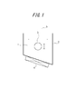
- FIG. 1 shows an example of a nitriding apparatus suitable for use in the first embodiment.
- reference numeral 1 is a molten salt bath
- 2 is a container containing the molten salt bath
- 3 is a sink roll
- 4 is a heating / temperature adjusting device
- 5 is a strip (steel plate).
- a salt bath containing cyanate as a main component for example, a mixed salt bath of alkali cyanate, alkali cyanide and alkali carbonate, alkali cyanate and cyanuric, or the like.
- a mixed salt bath of an acid alkali and an alkali carbonate is advantageously suitable, but is not limited to this, and any salt bath (electrolyte salt bath) capable of nitriding the strip can be used.
- the molten salt bath 1 in the container 2 can be heated and maintained at a desired temperature by the heating / temperature adjusting device 4.
- the installation position is not limited to this position, The appropriate position inside and outside of the container 2 is shown. It is sufficient to arrange as many as necessary.
- the temperature of the molten salt bath is preferably about 400 to 700 ° C.
- the immersion time is preferably about 5 to 1000 s.
- the nitriding amount by the above nitriding treatment is preferably 50 ppm or more and 3000 ppm or less. This is because if the amount of nitriding is less than 50 ppm, the effect cannot be obtained sufficiently, while if it exceeds 3000 ppm, the amount of precipitation of silicon nitride or the like becomes excessive, and secondary recrystallization hardly occurs.
- a preferable nitriding amount is in a range of 150 ppm to 1000 ppm.
- the sink roll 3 immersed in the molten salt bath 1 is at least vertically movable or horizontally movable (up and down in FIG. 1) so that the strip 5 is immersed in the molten salt bath.
- the distance and thus the immersion time can be adjusted. Therefore, when it is necessary to change the plate passing speed during plate passing, the immersion time is kept constant by adjusting the strip immersion distance by moving the sink roll appropriately in the vertical direction or horizontal direction. Even when it is necessary to change the immersion time for each strip, it can be easily handled.
- the movement of the sink roll is not limited to the vertical direction or the horizontal direction, and may be moved in other directions such as an oblique direction.
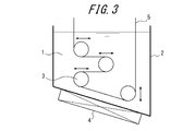
- FIG. 1 shows a case where one sink roll 3 is arranged in the molten salt bath 1, but a plurality of the sink rolls 3 can also be arranged in the molten salt bath as shown in FIGS.
- the range in which the immersion time can be made constant can be expanded even when it is necessary to change the plate passing speed. Appropriate measures can be taken without increasing the length, and running costs can be reduced.
- FIG. 4 shows the case where the sink roll 3 is disposed in the molten salt bath and the deflector roll 6 is disposed outside the molten salt bath.
- the strip 5 is adjacent to the sink roll 3 in the molten salt bath.
- the immersion time can also be adjusted by wrapping between the deflector rolls 6 outside the bath. In actual equipment, these methods may be appropriately selected and applied in accordance with the required immersion time and the adjustment amount.
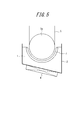
- FIG. 5 shows an example of a nitriding apparatus suitable for use in the implementation of the second embodiment.
- reference numeral 1 is a molten salt bath
- 2 is a container containing the molten salt bath 1
- 3 is a sink roll
- 4 is a heating / temperature adjusting device
- 5 is a strip (steel plate)
- 7 is a counter electrode.
- the sink roll 3 is a semi-immersed roll 3 a in which the lower half of the roll is immersed in the molten salt bath 1 as illustrated.
- the semi-immersed roll 3a also functions as an electrode roll that also serves as an electrode for applying a voltage to the strip.
- a suitable molten salt bath is the same as that in the first embodiment.
- the molten salt bath 1 in the container 2 is the same as in the first embodiment in that the molten salt bath 1 is heated and maintained at a desired temperature by the heating / temperature adjusting device 4.
- the strip 5 is immersed in the molten salt bath 1 through the semi-immersed roll 3a, and between the semi-immersed roll 3a (electrode roll) and the counter electrode provided opposite to the semi-immersed roll 3a.
- the surface of the strip 5 is nitrided under a stable plate and in a short time.
- nitriding apparatus shown in FIG. 5 nitriding can be performed only on one side of the strip. Therefore, when nitriding is performed on both sides of the strip, another pair of nitriding apparatuses is required.
- the temperature of the molten salt bath is preferably about 300 to 700 ° C. Particularly preferred is a range of 400 to 600 ° C.
- the immersion time is preferably about 3 to 300 s. Particularly preferred is the range of 3 to 100 s.
- the nitriding time can be shortened to about 1 ⁇ 2 compared to the case where such electrolytic treatment is not performed.
- the nitriding amount by the nitriding treatment is preferably 50 ppm or more and 3000 ppm or less, as in the case described in the first embodiment.
- the applied voltage that is, the current density is changed. Therefore, a simple and quick response is possible.
- the current density during energization is preferably about 1 to 20 A / dm 2. Within this range, the current density is appropriately determined in consideration of the electrode life and nitriding efficiency. Adjust it.
- FIG. 5 shows a case where the sink roll 3 is a semi-immersed roll 3a.
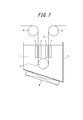
- the sink roll 3 is a completely immersed roll 3b, and the sink roll 3 is introduced into and discharged from the molten salt via the fully immersed roll 3b.
- a counter electrode 7 for applying a voltage is provided on both sides of the strip 5 and nitriding by electrolytic treatment is performed on both sides of the strip 5.
- the complete immersion roll 3b also serves as an electrode roll.
- the counter electrodes 7 are disposed on both sides of the strip 5, and both surfaces of the strip can be uniformly processed at a time, so that nitriding can be performed in a shorter time.
- FIG. 7 shows that the power supply to the strip 5 is performed from the electrode roll 8 installed outside the molten salt bath.
- the processing method and the processing apparatus of the present invention perform not only the nitriding treatment but also the carburizing / nitriding treatment or the sulfurizing / nitriding treatment. It can also be applied when applied.
- the apparatus of the present invention may be an independent facility for continuously performing nitriding treatment or the like, but it may be attached to a process line for performing other treatments, and if it is a continuous line, an optimum location including efficiency is provided. It only has to be attached to.
- the strip that is the material to be treated is not particularly limited, and any conventionally known strip can be used as long as it is a directional electromagnetic steel strip.
- any conventionally known strip can be used as long as it is a directional electromagnetic steel strip.
- limiting in particular about processes other than the nitriding process using a molten salt bath during the manufacturing process of a grain-oriented electrical steel strip All the conventionally well-known manufacturing processes can be applied.
- Example 1 Continuously cast slabs for grain-oriented electrical steel sheets containing 3.3% by mass of Si are heated to slabs and then hot-rolled to a thickness of 2.5mm, then hot-rolled and annealed, and then cold-rolled to obtain thickness.
- the nitriding amount was measured for each of the front and back surfaces of the strip after nitriding treatment thus obtained, and the difference in the nitriding amount between the front and back surfaces was investigated.
- the nitriding amount was measured by chemical analysis after cutting out a 50 mm ⁇ 30 mm nitriding sample and grinding and polishing the opposite side of the measurement surface to the center of the plate thickness. The obtained results are also shown in Table 1.
- the difference in nitriding amount on the front and back surfaces was very small as less than 7%, and as a result, the strip with little variation in nitriding amount was obtained. It can be seen that is obtained stably.
- Example 2 Continuously cast slabs for grain-oriented electrical steel sheets containing 3.3% by mass of Si are heated to slabs and then hot-rolled to a thickness of 2.5mm, then hot-rolled and annealed, and then cold-rolled to obtain thickness.
- the nitriding amount was measured for each of the front and back surfaces of the strip after nitriding treatment thus obtained, and the difference in the nitriding amount between the front and back surfaces was investigated.
- the nitriding amount was measured by chemical analysis after cutting out a 50 mm ⁇ 30 mm nitriding sample and grinding and polishing the opposite side of the measurement surface to the center of the plate thickness. The obtained results are also shown in Table 2.
- the difference in nitriding amount on the front and back surfaces was very small as less than 7%, and as a result, the strip with little variation in nitriding amount was obtained. It can be seen that is obtained stably.
Abstract
Description
さらに、このようなガス窒化工程においてストリップ全体にわたり均一に窒化するために、ノズルまたはスプレーで供給する窒化ガスを鋼板中央部と鋼板両端部で分割して調整する方法が提案されている(特許文献7)。
また、特許文献5~7に開示された技術では、窒化性ガスを鋼板に吹付けて窒化する方法であるため、炉内温度の時間的・位置的な不均一や熱による配管中での窒化性ガスの分解量の違いなどにより、窒化増量がストリップの部所によって異なる場合があり、結果的に二次再結晶が不均一となり磁気特性の悪化につながる場合があった。
その結果、ストリップ(鋼板)に対して窒化を行う場合、
(1) 気相からの反応による窒素添加では、処理時の温度や表面の反応性などに大きく影響を受けるため、バラツキの発生が避けられない、
(2) この点、窒化処理自体を液相からの反応とする、具体的には溶融塩中で行うことにより、バラツキを生じさせる原因となる上述した因子の影響を最小限に止めることができ、その結果、優れた磁気特性が全ストリップ内で安定して得られる
との知見を得た。
浸漬時間の精密制御としては、本来、バッチ処理の方が有利であるが、方向性電磁鋼板の場合、窒化処理を、総重量が数トンから数十トンに及ぶストリップに対して連続的に行う必要がある。また、ストリップを連続して通板させる場合には、ストリップの厚さや必要窒化量によって窒化量を変更させたり、通板中に通板速度を変更させる必要が生じるため、それらに対する対応が必要となる。
(3) 溶融塩浴の内部に設置するシンクロールを移動可能として、溶融塩浴中におけるストリップの移動距離を調整する方法が有利である、
(4) また、溶融塩中で窒化を行う場合は、通電よって窒化量を制御することができ、しかもこの通電を利用する場合には、窒化に要する時間の短縮化を図ることができる
との知見を得た。
本発明は、上記の知見に基づいて完成されたものである。
1.方向性電磁鋼板の製造工程中、冷間圧延後、二次再結晶焼鈍前の段階において、ストリップを溶融塩浴に浸漬させることにより、該ストリップに対し連続的に窒化処理を施す方向性電磁鋼板の窒化処理方法。
また、とくに通電よって窒化量を制御する場合は、生産効率に直接影響する窒化時間の短縮も可能である。
本発明において、ストリップを溶融塩浴に単に浸漬させて窒化処理を施す場合を第1の実施態様と、またストリップを溶融塩浴に浸漬させつつ、電解処理を行って窒化処理を施す場合を第2の実施態様と呼ぶものとし、以下、各実施態様をそれぞれ個別に説明する。
図1に、第1の実施態様の実施に用いて好適な窒化処理装置の一例を示す。図中、符号1は溶融塩浴、2は溶融塩浴1を収容した容器、3はシンクロール、4は加熱・温度調整装置、そして5がストリップ(鋼板)である。
また、容器2内の溶融塩浴1は、加熱・温度調整装置4によって所望の温度に加熱・保持することができる。なお、図1では、加熱・温度調整装置を、容器2の外側底部に設置した例を示したが、その設置位置は、この位置に限定されるものではなく、容器2の内外の適切な位置に必要な数だけ配置すれば良い。
ここに、溶融塩浴の温度は400~700℃程度、また浸漬時間は5~1000s程度とするのが好ましい。
さらに、上記の窒化処理による窒化量は、50ppm以上3000ppm以下とすることが好ましい。というのは、窒化量が50ppm未満では、その効果は十分に得られず、一方3000ppmを超えると窒化珪素などの析出量が過多となって二次再結晶が生じ難くなるからである。好ましい窒化量は150ppm以上1000ppm以下の範囲である。
従って、通板中に通板速度の変更が必要となった場合には、シンクロールを適宜、上下方向または水平方向に移動させて、ストリップの浸漬距離を調整することにより、浸漬時間を一定に保つことができ、またストリップ毎に浸漬時間を変更することが必要となった場合においても容易に対応が可能である。
なお、シンクロールの移動は、上下方向または水平方向に限るものではなく、斜め方向などその他の方向に移動させてもよいことは言うまでもない。
実際の設備では、必要な浸漬時間やその調整量などに応じて、これらの手法を適宜選択して適用すればよい。
図5に、第2の実施態様の実施に用いて好適な窒化処理装置の一例を示す。図中、符号1は溶融塩浴、2は溶融塩浴1を収容した容器、3はシンクロール、4は加熱・温度調整装置、5はストリップ(鋼板)、そして7が対極である。
この例では、シンクロール3を、図示したとおり、ロールの下半分が溶融塩浴1内に浸漬した半浸漬ロール3aとしている。また、この半浸漬ロール3aは、ストリップに対して電圧を印加する電極を兼ねた電極ロールとしても機能させる。
また、容器2内の溶融塩浴1を、加熱・温度調整装置4によって所望の温度に加熱・保持する点でも第1の実施態様の場合と同じである。
なお、図5に示した窒化処理装置では、ストリップの片面のみしか窒化処理ができないので、ストリップの両面に窒化を施す場合には、もう一対の窒化処理装置が必要となる。
ここに、上記した必要窒化量を得るには、通電時における電流密度は1~20A/dm2程度とすることが好ましく、この範囲内で電極寿命や窒化効率などを勘案して適宜電流密度を調整すれば良い。
この場合は、ストリップ5の両側に対極7が配置されていて、ストリップの両面を一度に均一に処理できるので、より短時間での窒化が可能となる。
また、本発明の装置は、窒化処理などを連続的に行う独立した設備としてもよいが、他の処理を施す工程ラインに取り付けても良く、連続ラインであれば効率面を含めて最適な箇所に取り付けていればよい。
また、本発明では、方向性電磁鋼ストリップの製造工程中、溶融塩浴を用いた窒化処理工程以外の工程については特に制限はなく、従来から公知の製造工程をいずれも適用することができる。
Siを3.3質量%含有する方向性電磁鋼板用の連鋳スラブを、スラブ加熱後、熱間圧延により板厚:2.5mmの熱延板とし、ついで熱延板焼鈍後、冷間圧延により板厚:0.22mmの最終板厚とし、ついで一次再結晶焼鈍を施したストリップに対して、表1に示す条件で、溶融塩浴を用いた窒化処理を施した。
かくして得られた窒化処理後のストリップの表裏面それぞれについて窒化量を測定し、表裏面における窒化量の差を調査した。なお、窒化量の測定は、50mm×30mmの窒化量測定用サンプルを切出し、測定面の反対側を板厚中央部まで研削・研磨したのち、化学分析により行った。
得られた結果を表1に併記する。

Siを3.3質量%含有する方向性電磁鋼板用の連鋳スラブを、スラブ加熱後、熱間圧延により板厚:2.5mmの熱延板とし、ついで熱延板焼鈍後、冷間圧延により板厚:0.22mmの最終板厚とし、ついで一次再結晶焼鈍を施したストリップに対して、表2に示す条件で、溶融塩浴を用いた電解処理による窒化を施した。
かくして得られた窒化処理後のストリップの表裏面それぞれについて窒化量を測定し、表裏面における窒化量の差を調査した。なお、窒化量の測定は、50mm×30mmの窒化量測定用サンプルを切出し、測定面の反対側を板厚中央部まで研削・研磨したのち、化学分析により行った。
得られた結果を表2に併記する。

2 容器
3 シンクロール
4 加熱・温度調整装置
5 ストリップ(鋼板)
6 デフレクターロール
7 対極
8 電極ロール
Claims (14)
- 方向性電磁鋼板の製造工程中、冷間圧延後、二次再結晶焼鈍前の段階において、ストリップを溶融塩浴に浸漬させることにより、該ストリップに対し連続的に窒化処理を施す方向性電磁鋼板の窒化処理方法。
- 前記溶融塩浴の内部に、上下移動または水平移動が可能なシンクロールを設置し、このシンクロールを移動させることにより、ストリップの溶融塩浴内における浸漬時間を調整可能とする請求項1に記載の方向性電磁鋼板の窒化処理方法。
- 前記ストリップの溶融塩浴浸漬に際し、溶融塩浴の温度を400~700℃、浸漬時間を5~1000sとする請求項1または2に記載の方向性電磁鋼板の窒化処理方法。
- 方向性電磁鋼板の製造工程中、冷間圧延後、二次再結晶焼鈍前の段階において、ストリップを、電解質の溶融塩浴に浸漬させつつ、該ストリップと対極との間に電圧を印加して電解処理することにより、該ストリップに対し連続的に窒化処理を施す方向性電磁鋼板の窒化処理方法。
- 前記電解処理における電流密度を変更することにより、ストリップに対する窒化量を調整する請求項4に記載の方向性電磁鋼板の窒化処理方法。
- 前記ストリップの溶融塩浴浸漬に際し、溶融塩浴の温度を300~700℃、浸漬時間を3~300sとする請求項4または5に記載の方向性電磁鋼板の窒化処理方法。
- 請求項1乃至3のいずれかに記載の方向性電磁鋼板の窒化処理方法を実施するための装置であって、溶融塩浴を保持する容器と、溶融塩浴を加熱し所定の温度に保持するための加熱・温度調整装置と、溶融塩浴内を通板するストリップを支持するシンクロールを有する方向性電磁鋼板の窒化処理装置。
- 請求項7において、溶融塩浴内に配置したシンクロールを上下移動または水平移動可能として、ストリップの溶融塩浴内における浸漬距離を変更可能とした方向性電磁鋼板の窒化処理装置。
- 請求項7または8において、溶融塩浴内に上下移動または水平移動が可能なシンクロールを複数個配設し、各シンクロールを移動させることによりストリップの溶融塩浴内における浸漬距離を変更可能とした方向性電磁鋼板の窒化処理装置。
- 請求項7乃至9のいずれかにおいて、溶融塩浴内に上下移動または水平移動が可能なシンクロールを複数個配置すると共に、溶融塩浴外にも上下移動または水平移動が可能なデフレクターロールを複数個配置し、ストリップをこれらシンクロールとデフレクターロール間を掛け回すことにより、溶融塩浴内における浸漬距離を変更可能とした方向性電磁鋼板の窒化処理装置。
- 請求項4乃至6のいずれかに記載の方向性電磁鋼板の窒化処理方法を実施するための装置であって、溶融塩浴を保持する容器と、溶融塩浴を加熱し所定の温度に保持するための加熱・温度調整装置と、溶融塩浴内を通板するストリップを支持するシンクロールと、溶融塩浴内を通板するストリップに対して電圧を印加するための電極を有する方向性電磁鋼板の窒化処理装置。
- 請求項11において、上記シンクロールを、ストリップに対して電圧を印加する電極を兼ねた電極ロールとし、これに対向させて溶融塩浴内に対極を設けた方向性電磁鋼板の窒化処理装置。
- 請求項11において、ストリップに対して電圧を印加する対極を、溶融塩内を通板するストリップの両側に設置した方向性電磁鋼板の窒化処理装置。
- 請求項13において、ストリップへの給電を溶融塩浴外に設置した電極ロールを介して行う方向性電磁鋼板の窒化処理装置。
Priority Applications (5)
| Application Number | Priority Date | Filing Date | Title |
|---|---|---|---|
| EP14750977.2A EP2957651B1 (en) | 2013-02-18 | 2014-02-18 | Method and device for nitriding grain-oriented electrical steel sheet |
| KR1020157024706A KR101662971B1 (ko) | 2013-02-18 | 2014-02-18 | 방향성 전기 강판의 질화 처리 방법 및 질화 처리 장치 |
| US14/764,650 US10214793B2 (en) | 2013-02-18 | 2014-02-18 | Method and device for nitriding grain-oriented electrical steel sheet |
| RU2015139583A RU2620403C2 (ru) | 2013-02-18 | 2014-02-18 | Способ и устройство для азотирования текстурированного листа из электротехнической стали |
| CN201480009184.6A CN104995327B (zh) | 2013-02-18 | 2014-02-18 | 方向性电磁钢板的氮化处理方法及氮化处理装置 |
Applications Claiming Priority (4)
| Application Number | Priority Date | Filing Date | Title |
|---|---|---|---|
| JP2013029380A JP5942887B2 (ja) | 2013-02-18 | 2013-02-18 | 方向性電磁鋼板の窒化処理方法および窒化処理装置 |
| JP2013-029380 | 2013-02-18 | ||
| JP2013-029358 | 2013-02-18 | ||
| JP2013029358A JP5942885B2 (ja) | 2013-02-18 | 2013-02-18 | 方向性電磁鋼板の窒化処理方法および窒化処理装置 |
Publications (2)
| Publication Number | Publication Date |
|---|---|
| WO2014125840A1 true WO2014125840A1 (ja) | 2014-08-21 |
| WO2014125840A8 WO2014125840A8 (ja) | 2015-08-06 |
Family
ID=51353851
Family Applications (1)
| Application Number | Title | Priority Date | Filing Date |
|---|---|---|---|
| PCT/JP2014/000818 WO2014125840A1 (ja) | 2013-02-18 | 2014-02-18 | 方向性電磁鋼板の窒化処理方法および窒化処理装置 |
Country Status (6)
| Country | Link |
|---|---|
| US (1) | US10214793B2 (ja) |
| EP (1) | EP2957651B1 (ja) |
| KR (1) | KR101662971B1 (ja) |
| CN (1) | CN104995327B (ja) |
| RU (1) | RU2620403C2 (ja) |
| WO (1) | WO2014125840A1 (ja) |
Cited By (1)
| Publication number | Priority date | Publication date | Assignee | Title |
|---|---|---|---|---|
| CN104775089A (zh) * | 2015-03-12 | 2015-07-15 | 常州大学 | 一种施加磁场快速盐浴氮化的方法 |
Families Citing this family (3)
| Publication number | Priority date | Publication date | Assignee | Title |
|---|---|---|---|---|
| CN111321369A (zh) * | 2020-03-05 | 2020-06-23 | 马鞍山钢铁股份有限公司 | 用于取向硅钢生产的离子氮化装置及其离子氮化方法 |
| CN111500975B (zh) * | 2020-05-29 | 2023-11-17 | 江苏奕华新材料科技有限公司 | 一种减震器储油缸表面处理方法 |
| CN111500976B (zh) * | 2020-05-29 | 2023-08-22 | 江苏奕华新材料科技有限公司 | 一种用于氮碳氧共渗技术的渗氮剂及其制备方法 |
Citations (11)
| Publication number | Priority date | Publication date | Assignee | Title |
|---|---|---|---|---|
| US1965559A (en) | 1933-08-07 | 1934-07-03 | Cold Metal Process Co | Electrical sheet and method and apparatus for its manufacture and test |
| JPS5113469B2 (ja) | 1972-10-13 | 1976-04-28 | ||
| JPH03122227A (ja) | 1989-10-05 | 1991-05-24 | Nippon Steel Corp | 方向性電磁鋼板の脱炭連続焼鈍炉 |
| JPH03277726A (ja) * | 1990-03-28 | 1991-12-09 | Nippon Stainless Steel Co Ltd | 鋼帯の連続塩浴槽 |
| JPH09118964A (ja) * | 1995-05-16 | 1997-05-06 | Armco Inc | 高い体積抵抗率を有する粒子方向性珪素鋼およびその製造法 |
| JP2771634B2 (ja) | 1989-10-05 | 1998-07-02 | 新日本製鐵株式会社 | 方向性電磁鋼板の脱炭連続焼鈍炉 |
| JP2004232005A (ja) * | 2003-01-29 | 2004-08-19 | Japan Science & Technology Agency | 鋼材の電気化学的表面窒化処理法 |
| JP2005314775A (ja) * | 2004-04-30 | 2005-11-10 | Iox:Kk | 溶融塩中での金属窒化物薄膜形成法 |
| JP3940205B2 (ja) | 1997-06-30 | 2007-07-04 | 新日本製鐵株式会社 | 長手・幅方向偏差に小さい方向性電磁鋼板の窒化処理方法とそのための装置 |
| JP2009052104A (ja) * | 2007-08-28 | 2009-03-12 | Doshisha | 溶融塩電気化学プロセスを用いた表面窒化処理方法 |
| JP4321120B2 (ja) | 2003-05-29 | 2009-08-26 | Jfeスチール株式会社 | 磁気特性に優れた方向性電磁鋼板の製造方法 |
Family Cites Families (11)
| Publication number | Priority date | Publication date | Assignee | Title |
|---|---|---|---|---|
| US3087505A (en) * | 1960-12-15 | 1963-04-30 | Allegheny Ludlum Steel | Pickling apparatus |
| US3174491A (en) * | 1963-10-23 | 1965-03-23 | Kolene Corp | Molten salt spray apparatus for descaling stainless steel |
| AT329358B (de) | 1974-06-04 | 1976-05-10 | Voest Ag | Schwingmuhle zum zerkleinern von mahlgut |
| US4119109A (en) * | 1977-02-17 | 1978-10-10 | Allegheny Ludlum Industries, Inc. | Apparatus for treating strip |
| DE4208577A1 (de) * | 1992-03-13 | 1993-09-16 | Mannesmann Ag | Verfahren zum mehrlagigen beschichten von strangfoermigem gut |
| JP3277726B2 (ja) * | 1994-10-18 | 2002-04-22 | ソニー株式会社 | 2段階エピタキシャル成長方法 |
| US5804053A (en) * | 1995-12-07 | 1998-09-08 | Eltech Systems Corporation | Continuously electroplated foam of improved weight distribution |
| IT1316029B1 (it) | 2000-12-18 | 2003-03-26 | Acciai Speciali Terni Spa | Processo per la produzione di acciaio magnetico a grano orientato. |
| JP3748425B2 (ja) * | 2002-09-04 | 2006-02-22 | パーカー熱処理工業株式会社 | 耐食性を強化された金属部材の塩浴窒化方法 |
| JP4015644B2 (ja) | 2004-05-31 | 2007-11-28 | 株式会社ソニー・コンピュータエンタテインメント | 画像処理装置及び画像処理方法 |
| KR101651797B1 (ko) * | 2012-12-28 | 2016-08-26 | 제이에프이 스틸 가부시키가이샤 | 방향성 전기 강판의 제조 방법 |
-
2014
- 2014-02-18 RU RU2015139583A patent/RU2620403C2/ru active
- 2014-02-18 US US14/764,650 patent/US10214793B2/en active Active
- 2014-02-18 EP EP14750977.2A patent/EP2957651B1/en active Active
- 2014-02-18 WO PCT/JP2014/000818 patent/WO2014125840A1/ja active Application Filing
- 2014-02-18 KR KR1020157024706A patent/KR101662971B1/ko active IP Right Grant
- 2014-02-18 CN CN201480009184.6A patent/CN104995327B/zh active Active
Patent Citations (11)
| Publication number | Priority date | Publication date | Assignee | Title |
|---|---|---|---|---|
| US1965559A (en) | 1933-08-07 | 1934-07-03 | Cold Metal Process Co | Electrical sheet and method and apparatus for its manufacture and test |
| JPS5113469B2 (ja) | 1972-10-13 | 1976-04-28 | ||
| JPH03122227A (ja) | 1989-10-05 | 1991-05-24 | Nippon Steel Corp | 方向性電磁鋼板の脱炭連続焼鈍炉 |
| JP2771634B2 (ja) | 1989-10-05 | 1998-07-02 | 新日本製鐵株式会社 | 方向性電磁鋼板の脱炭連続焼鈍炉 |
| JPH03277726A (ja) * | 1990-03-28 | 1991-12-09 | Nippon Stainless Steel Co Ltd | 鋼帯の連続塩浴槽 |
| JPH09118964A (ja) * | 1995-05-16 | 1997-05-06 | Armco Inc | 高い体積抵抗率を有する粒子方向性珪素鋼およびその製造法 |
| JP3940205B2 (ja) | 1997-06-30 | 2007-07-04 | 新日本製鐵株式会社 | 長手・幅方向偏差に小さい方向性電磁鋼板の窒化処理方法とそのための装置 |
| JP2004232005A (ja) * | 2003-01-29 | 2004-08-19 | Japan Science & Technology Agency | 鋼材の電気化学的表面窒化処理法 |
| JP4321120B2 (ja) | 2003-05-29 | 2009-08-26 | Jfeスチール株式会社 | 磁気特性に優れた方向性電磁鋼板の製造方法 |
| JP2005314775A (ja) * | 2004-04-30 | 2005-11-10 | Iox:Kk | 溶融塩中での金属窒化物薄膜形成法 |
| JP2009052104A (ja) * | 2007-08-28 | 2009-03-12 | Doshisha | 溶融塩電気化学プロセスを用いた表面窒化処理方法 |
Non-Patent Citations (1)
| Title |
|---|
| "The Surface Finishing Society of Japan", HYOMEN GIJUTSU BINRAN, 27 February 1998 (1998-02-27), pages 890 - 891, XP055216792 * |
Cited By (1)
| Publication number | Priority date | Publication date | Assignee | Title |
|---|---|---|---|---|
| CN104775089A (zh) * | 2015-03-12 | 2015-07-15 | 常州大学 | 一种施加磁场快速盐浴氮化的方法 |
Also Published As
| Publication number | Publication date |
|---|---|
| US10214793B2 (en) | 2019-02-26 |
| EP2957651B1 (en) | 2019-03-13 |
| US20150368732A1 (en) | 2015-12-24 |
| CN104995327A (zh) | 2015-10-21 |
| KR101662971B1 (ko) | 2016-10-05 |
| EP2957651A1 (en) | 2015-12-23 |
| RU2015139583A (ru) | 2017-03-23 |
| KR20150119124A (ko) | 2015-10-23 |
| WO2014125840A8 (ja) | 2015-08-06 |
| EP2957651A4 (en) | 2016-03-16 |
| CN104995327B (zh) | 2018-04-03 |
| RU2620403C2 (ru) | 2017-05-25 |
Similar Documents
| Publication | Publication Date | Title |
|---|---|---|
| TWI592503B (zh) | 無方向性電磁鋼板的製造方法 | |
| KR20190071745A (ko) | 전자 강판 제조용의 열연 강판 및 그의 제조 방법 | |
| WO2018117671A1 (ko) | 방향성 전기강판의 제조방법 | |
| WO2014125840A1 (ja) | 方向性電磁鋼板の窒化処理方法および窒化処理装置 | |
| EP2957652A1 (en) | Apparatus and method for nitriding grain-oriented electrical steel sheet | |
| JP6252833B2 (ja) | マルテンサイト系ステンレス鋼鋼帯の製造方法 | |
| CN108779509B (zh) | 取向性电磁钢板的制造方法及生产设备线 | |
| US20140255720A1 (en) | Ultrathin electromagnetic steel sheet | |
| EP3859019A1 (en) | Grain-oriented electrical steel sheet and method for manufacturing same | |
| KR100779579B1 (ko) | 철손이 낮고 자속밀도가 높은 무방향성 전기강판의제조방법 | |
| CN107460292A (zh) | 一种提高低温高磁感取向硅钢边部性能的加工方法 | |
| WO2013147155A1 (ja) | 炭素工具鋼鋼帯の製造方法 | |
| JP7106910B2 (ja) | 方向性電磁鋼板の製造方法 | |
| KR20150108385A (ko) | 방향성 전기 강판의 질화 처리 설비 및 질화 처리 방법 | |
| CN113165033A (zh) | 无取向性电磁钢板的制造方法 | |
| JP5942885B2 (ja) | 方向性電磁鋼板の窒化処理方法および窒化処理装置 | |
| JP6094504B2 (ja) | 方向性電磁鋼板の竪型窒化処理設備および窒化処理方法 | |
| JP5942887B2 (ja) | 方向性電磁鋼板の窒化処理方法および窒化処理装置 | |
| JP6137490B2 (ja) | 一次再結晶集合組織の予測方法および方向性電磁鋼板の製造方法 | |
| KR20180072106A (ko) | 방향성 전기강판의 제조방법 | |
| KR100530069B1 (ko) | 응력제거소둔 후 철손이 낮고 자속밀도가 높은 무방향성전기강판의 제조방법 | |
| JP2019002039A (ja) | レーザー磁区制御用方向性電磁鋼板とその製造方法 | |
| KR100721819B1 (ko) | 철손이 낮고 자속밀도가 높은 방향성 전기강판 제조방법 | |
| JP4211540B2 (ja) | 方向性電磁鋼板の連続式熱間圧延設備列 | |
| KR20150074862A (ko) | 무방향성 전기강판 및 그 제조방법 |
Legal Events
| Date | Code | Title | Description |
|---|---|---|---|
| 121 | Ep: the epo has been informed by wipo that ep was designated in this application |
Ref document number: 14750977 Country of ref document: EP Kind code of ref document: A1 |
|
| WWE | Wipo information: entry into national phase |
Ref document number: 14764650 Country of ref document: US |
|
| WWE | Wipo information: entry into national phase |
Ref document number: 2014750977 Country of ref document: EP |
|
| NENP | Non-entry into the national phase |
Ref country code: DE |
|
| ENP | Entry into the national phase |
Ref document number: 20157024706 Country of ref document: KR Kind code of ref document: A |
|
| ENP | Entry into the national phase |
Ref document number: 2015139583 Country of ref document: RU Kind code of ref document: A |