WO2014119513A1 - Dispositif de commande de quantité d'eau de mer pour épurateur, procédé de commande de quantité d'eau de mer pour épurateur, dispositif de commande de quantité d'alcali, et procédé de commande de quantité d'alcali - Google Patents
Dispositif de commande de quantité d'eau de mer pour épurateur, procédé de commande de quantité d'eau de mer pour épurateur, dispositif de commande de quantité d'alcali, et procédé de commande de quantité d'alcali Download PDFInfo
- Publication number
- WO2014119513A1 WO2014119513A1 PCT/JP2014/051672 JP2014051672W WO2014119513A1 WO 2014119513 A1 WO2014119513 A1 WO 2014119513A1 JP 2014051672 W JP2014051672 W JP 2014051672W WO 2014119513 A1 WO2014119513 A1 WO 2014119513A1
- Authority
- WO
- WIPO (PCT)
- Prior art keywords
- seawater
- amount
- scrubber
- alkali
- exhaust gas
- Prior art date
Links
Images


Classifications
-
- B—PERFORMING OPERATIONS; TRANSPORTING
- B01—PHYSICAL OR CHEMICAL PROCESSES OR APPARATUS IN GENERAL
- B01D—SEPARATION
- B01D53/00—Separation of gases or vapours; Recovering vapours of volatile solvents from gases; Chemical or biological purification of waste gases, e.g. engine exhaust gases, smoke, fumes, flue gases, aerosols
- B01D53/14—Separation of gases or vapours; Recovering vapours of volatile solvents from gases; Chemical or biological purification of waste gases, e.g. engine exhaust gases, smoke, fumes, flue gases, aerosols by absorption
- B01D53/18—Absorbing units; Liquid distributors therefor
- B01D53/185—Liquid distributors
-
- B—PERFORMING OPERATIONS; TRANSPORTING
- B01—PHYSICAL OR CHEMICAL PROCESSES OR APPARATUS IN GENERAL
- B01D—SEPARATION
- B01D53/00—Separation of gases or vapours; Recovering vapours of volatile solvents from gases; Chemical or biological purification of waste gases, e.g. engine exhaust gases, smoke, fumes, flue gases, aerosols
- B01D53/34—Chemical or biological purification of waste gases
- B01D53/46—Removing components of defined structure
- B01D53/48—Sulfur compounds
- B01D53/50—Sulfur oxides
- B01D53/507—Sulfur oxides by treating the gases with other liquids
-
- B—PERFORMING OPERATIONS; TRANSPORTING
- B01—PHYSICAL OR CHEMICAL PROCESSES OR APPARATUS IN GENERAL
- B01D—SEPARATION
- B01D53/00—Separation of gases or vapours; Recovering vapours of volatile solvents from gases; Chemical or biological purification of waste gases, e.g. engine exhaust gases, smoke, fumes, flue gases, aerosols
- B01D53/14—Separation of gases or vapours; Recovering vapours of volatile solvents from gases; Chemical or biological purification of waste gases, e.g. engine exhaust gases, smoke, fumes, flue gases, aerosols by absorption
- B01D53/1412—Controlling the absorption process
-
- G—PHYSICS
- G05—CONTROLLING; REGULATING
- G05D—SYSTEMS FOR CONTROLLING OR REGULATING NON-ELECTRIC VARIABLES
- G05D7/00—Control of flow
- G05D7/06—Control of flow characterised by the use of electric means
- G05D7/0617—Control of flow characterised by the use of electric means specially adapted for fluid materials
- G05D7/0629—Control of flow characterised by the use of electric means specially adapted for fluid materials characterised by the type of regulator means
- G05D7/0676—Control of flow characterised by the use of electric means specially adapted for fluid materials characterised by the type of regulator means by action on flow sources
- G05D7/0682—Control of flow characterised by the use of electric means specially adapted for fluid materials characterised by the type of regulator means by action on flow sources using a plurality of flow sources
-
- G—PHYSICS
- G05—CONTROLLING; REGULATING
- G05D—SYSTEMS FOR CONTROLLING OR REGULATING NON-ELECTRIC VARIABLES
- G05D9/00—Level control, e.g. controlling quantity of material stored in vessel
- G05D9/12—Level control, e.g. controlling quantity of material stored in vessel characterised by the use of electric means
-
- B—PERFORMING OPERATIONS; TRANSPORTING
- B01—PHYSICAL OR CHEMICAL PROCESSES OR APPARATUS IN GENERAL
- B01D—SEPARATION
- B01D2251/00—Reactants
- B01D2251/30—Alkali metal compounds
- B01D2251/304—Alkali metal compounds of sodium
-
- B—PERFORMING OPERATIONS; TRANSPORTING
- B01—PHYSICAL OR CHEMICAL PROCESSES OR APPARATUS IN GENERAL
- B01D—SEPARATION
- B01D2252/00—Absorbents, i.e. solvents and liquid materials for gas absorption
- B01D2252/10—Inorganic absorbents
- B01D2252/103—Water
- B01D2252/1035—Sea water
-
- B—PERFORMING OPERATIONS; TRANSPORTING
- B01—PHYSICAL OR CHEMICAL PROCESSES OR APPARATUS IN GENERAL
- B01D—SEPARATION
- B01D2258/00—Sources of waste gases
- B01D2258/02—Other waste gases
- B01D2258/0283—Flue gases
-
- B—PERFORMING OPERATIONS; TRANSPORTING
- B01—PHYSICAL OR CHEMICAL PROCESSES OR APPARATUS IN GENERAL
- B01D—SEPARATION
- B01D53/00—Separation of gases or vapours; Recovering vapours of volatile solvents from gases; Chemical or biological purification of waste gases, e.g. engine exhaust gases, smoke, fumes, flue gases, aerosols
- B01D53/34—Chemical or biological purification of waste gases
- B01D53/46—Removing components of defined structure
- B01D53/48—Sulfur compounds
- B01D53/50—Sulfur oxides
- B01D53/501—Sulfur oxides by treating the gases with a solution or a suspension of an alkali or earth-alkali or ammonium compound
-
- Y—GENERAL TAGGING OF NEW TECHNOLOGICAL DEVELOPMENTS; GENERAL TAGGING OF CROSS-SECTIONAL TECHNOLOGIES SPANNING OVER SEVERAL SECTIONS OF THE IPC; TECHNICAL SUBJECTS COVERED BY FORMER USPC CROSS-REFERENCE ART COLLECTIONS [XRACs] AND DIGESTS
- Y10—TECHNICAL SUBJECTS COVERED BY FORMER USPC
- Y10T—TECHNICAL SUBJECTS COVERED BY FORMER US CLASSIFICATION
- Y10T137/00—Fluid handling
- Y10T137/0318—Processes
- Y10T137/0324—With control of flow by a condition or characteristic of a fluid
-
- Y—GENERAL TAGGING OF NEW TECHNOLOGICAL DEVELOPMENTS; GENERAL TAGGING OF CROSS-SECTIONAL TECHNOLOGIES SPANNING OVER SEVERAL SECTIONS OF THE IPC; TECHNICAL SUBJECTS COVERED BY FORMER USPC CROSS-REFERENCE ART COLLECTIONS [XRACs] AND DIGESTS
- Y10—TECHNICAL SUBJECTS COVERED BY FORMER USPC
- Y10T—TECHNICAL SUBJECTS COVERED BY FORMER US CLASSIFICATION
- Y10T137/00—Fluid handling
- Y10T137/8593—Systems
- Y10T137/85978—With pump
- Y10T137/85986—Pumped fluid control
- Y10T137/86027—Electric
Definitions
- the present invention relates to a seawater amount control device for seawater to be supplied as an absorption liquid to a scrubber for reducing the concentration of sulfur oxides (especially sulfur dioxide (SO 2 )) in exhaust gas, and supply as an absorption liquid.
- the present invention relates to a control device for the amount of alkali injected into seawater.
- the International Maritime Organization has a policy to gradually strengthen the sulfur content regulation of fuel oil in order to reduce sulfur oxide (SO x ) contained in the exhaust gas of ships.
- SO x sulfur oxide
- the regulation that the sulfur content is 0.5% or less is to be applied. For this reason, ship operators need to take measures such as using low-sulfur fuel or installing an exhaust gas treatment device in the main engine.
- a scrubber As an exhaust gas treatment apparatus in a ship, a scrubber is known that reduces the concentration of harmful substances in exhaust gas by passing the exhaust gas through seawater (see, for example, Patent Document 1 and Patent Document 2).
- the amount of seawater supplied to the scrubber needs to be injected according to the amount of sulfur oxide to be processed.
- seawater is supplied excessively, the pressure loss increases and the power of the seawater pump increases. If the amount of seawater is insufficient, the sulfur oxide concentration in the exhaust gas exceeds the regulation value, which becomes a problem.
- This invention is made
- An object of the present invention is to provide a seawater amount control device for a scrubber.
- This invention is made
- the present invention relates to a seawater amount control device for a scrubber that controls the amount of seawater supplied to a scrubber that is cleaned by contacting sulfur oxide contained in exhaust gas with seawater.
- a minimum seawater amount converter that calculates the minimum amount of seawater that is the minimum amount of seawater required for the sulfur oxide absorption reaction, and seawater in which the sulfur oxide contained in the exhaust gas exhausted from the scrubber into the atmosphere is below a set value
- a seawater amount correction converter for calculating a corrected seawater amount, an addition element for calculating the set seawater amount by adding the minimum seawater amount and the corrected seawater amount, and the seawater for the set seawater amount to the scrubber
- a pump control device for controlling to supply to the apparatus.
- the alkali component necessary for neutralization of the sulfur oxide contained in the consumed heavy oil is calculated as the minimum seawater amount, Calculate the corrected seawater volume so that the sulfur oxide concentration in the treated exhaust gas exhausted into the atmosphere does not exceed the emission regulation value, and control to supply the set seawater volume to the scrubber. ing.
- the amount of seawater supplied to the scrubber is not excessive or insufficient, and the amount of seawater appropriate for the scrubber is set so that the sulfur oxide concentration in the exhaust gas after treatment does not exceed the regulation value. It is possible to supply and perform stable operation.
- the alkali amount control device of the present invention is an alkali amount control device that controls the amount of alkali injected into seawater supplied to a scrubber that is cleaned by contacting sulfur oxide contained in exhaust gas with seawater, and includes engine output and fuel.
- a minimum seawater amount converter that calculates the minimum amount of seawater, which is the minimum amount of seawater required for absorption of sulfur oxides by seawater, from the sulfur content of oil, and sulfur oxides contained in exhaust gas exhausted from the scrubber to the atmosphere
- a seawater amount correction converter that calculates a corrected seawater amount that is a seawater amount that is equal to or less than a set value, an addition element that calculates a set seawater amount by adding the minimum seawater amount and the corrected seawater amount, and the set seawater
- a pump control device that controls the amount of seawater to be supplied to the scrubber, and an alkali amount calculation that calculates an alkali injection amount from the amount of alkali components contained in the seawater of the set amount
- it comprises a and an alkali
- the alkali component necessary for neutralization of sulfur oxides contained in the consumed heavy oil is calculated as the minimum amount of seawater from the engine output and the sulfur content of the heavy oil to be used. Calculate the corrected seawater volume so that the concentration of sulfur oxide contained in the treated exhaust gas exhausted to the exhaust emission level does not exceed the emission regulation value, and add the alkali injection volume to be injected into the seawater based on the set seawater volume. Calculated.
- a stable operation can be performed by supplying an appropriate amount of seawater to the scrubber so that the sulfur oxide concentration in the exhaust gas after treatment does not exceed the regulation value.
- FIG. 1 is a schematic diagram showing an exhaust gas treatment system centered on a scrubber according to a first embodiment.
- a system that removes sulfur dioxide (SO 2 ) contained in exhaust gas discharged from an engine used in a ship is considered.
- the present invention is not limited to this, and the exhaust gas treatment system according to the present embodiment is applicable to the treatment of various exhaust gases containing substances such as nitrogen oxide (NO x ) and sulfur oxide (SO x ).
- the exhaust gas treatment system includes a scrubber 10 to which exhaust gas is supplied from an engine 20, a seawater pump unit 30 including a seawater pressurization pump and a seawater extraction pump, a drainage tank 40, and filtration for filtering wastewater. It is mainly composed of a container unit 50.
- the exhaust gas discharged from the engine 20 is introduced into the scrubber 10.
- This exhaust gas contains 50 to 1500 ppm of sulfur dioxide (SO 2 ).
- SO 2 sulfur dioxide
- the seawater introduced into the scrubber 10 via the seawater pump unit 30 is sprayed and brought into gas-liquid contact.
- sulfur dioxide (SO 2 ) in the exhaust gas dissolves in seawater and dissociates into hydrogen ions and sulfite ions.
- Hydrogen ions react with an alkali component (NaHCO 3 ) in seawater as shown in the following formula (2).
- sulfite ions are oxidized to sulfate ions by air.
- the minimum amount of seawater required for the absorption reaction of sulfur dioxide (SO 2 ) by seawater is determined to be an amount that satisfies the reaction with the alkaline component shown in the formulas (2) and (3).
- Seawater has an alkalinity of about 105 ppm in terms of CaCO 3 .
- the exhaust gas from which sulfur dioxide (SO 2 ) has been removed in this way is exhausted from the top of the scrubber 10 into the atmosphere.
- the seawater sprayed in the scrubber 10 falls by its own weight along the inner wall surface of the scrubber 10 and is stored in a storage section below the scrubber 10.
- the stored seawater is drained into the drainage tank 40 via the seawater pump unit 30, then filtered by the filter unit 50 and drained to the ocean.
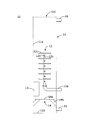
- FIG. 2 is a schematic cross-sectional view showing an example of the scrubber 10.
- the scrubber 10 sprays seawater (liquid) in a mist state in a scrubber main body 11 in which an internal space is formed in the vertical direction, and in a predetermined region in the vertical direction of the internal space of the scrubber main body 11 (
- Spraying device 12 for spraying) gas supply device 13 for introducing engine exhaust gas (gas) into scrubber body 11 from a position lower than a region where spraying device 12 sprays seawater, and a position lower than spraying device 12.
- Baffle 14 the spray device 12 is connected to the seawater pump unit 30 shown in FIG. 1, and the gas supply device 13 is connected to the engine 20 shown in FIG.
- the scrubber body 11 is composed of a cylindrical peripheral wall portion 11a and a circular bottom wall portion 11b. All the peripheral wall portions 11a are configured to have the same diameter. The upper end part of the surrounding wall part 11a is opened, and the opening part 11c is formed.
- the scrubber body 11 has a cylindrical shape, but the shape of the scrubber body 11 is not limited to this, and may be, for example, a rectangular tube shape.
- the spray device 12 is installed on the central axis of the scrubber body 11.
- the spray device 12 is inserted into the scrubber body 11 from the outside of the scrubber body 11, and is connected to a water supply pipe 12 a extending to the center position of the scrubber body 11 and an insertion end of the water supply pipe 12 a.
- a water pipe 12b as a trunk pipe extending over a predetermined region in the vertical direction of the space, a branch pipe 12c connected to the water pipe 12b and extending toward the peripheral wall portion 11a of the scrubber body 11, and at the tip of each branch pipe 12c
- a spray nozzle (not shown) that sprays the liquid supplied from the branch pipe 12c to a predetermined range.
- the branch pipes 12c are arranged in a plurality of stages in the vertical direction and intersect so that the branch pipes 12c adjacent in the vertical direction are orthogonal to each other.
- the gas supply device 13 is provided such that the gas ejection direction is along the tangential direction of the peripheral wall portion 11a of the scrubber body 11. Therefore, the exhaust gas introduced from the gas supply device 13 is injected in the horizontal direction along the inner peripheral surface of the peripheral wall portion 11a.
- the baffle 14 includes a disk part 14 a and leg parts 14 b that connect the disk part 14 a and the peripheral wall part 11 a of the scrubber body 11. A gap is formed between the outer peripheral portion of the disk portion 14a and the peripheral wall portion 11a of the scrubber body 11 for flowing liquid droplets.
- the baffle 14 divides the inside of the scrubber body 11 from a region where the liquid is sprayed by the spray device 12 and a region where the liquid for draining out of the scrubber body 11 is stored. Below the baffle 14, a drain pipe 15 for draining liquid outside the scrubber body 11 is provided below the baffle 14, a drain pipe 15 for draining liquid outside the scrubber body 11 is provided below the baffle 14, a drain pipe 15 for draining liquid outside the scrubber body 11 is provided below the baffle 14, a drain pipe 15 for draining liquid outside the scrubber body 11 is provided.
- an exhaust pipe 16 for taking out a part of the treated exhaust gas out of the scrubber main body 11 is provided.
- the exhaust pipe 16 is connected to an analyzer for sampling the treated exhaust gas.
- exhaust gas treatment in the scrubber 10 configured in this way will be described.
- the exhaust gas discharged from the engine is introduced by the gas supply device 13 below the region where the spray device 12 sprays liquid.
- the exhaust gas rises in the scrubber body 11 while circling along the peripheral wall portion 11a.
- seawater is introduced into the water conduit 12b through the water supply pipe 12a. And seawater is sprayed toward the surrounding wall part 11a of the scrubber main body 11 from the spray nozzle provided in the front-end
- the exhaust gas swirling and rising in the scrubber body 11 comes into gas-liquid contact with seawater sprayed from the spray nozzles provided in the branch pipes 12c installed in each stage, and sulfur dioxide (SO 2 ) in the exhaust gas is absorbed. Removed.
- the exhaust gas from which sulfur dioxide (SO 2 ) has been removed is exhausted into the atmosphere from an opening 11 c provided in the upper part of the scrubber body 11. A part of the exhaust gas is sent to the analyzer via the exhaust pipe 16.
- the seawater that has become droplets is pressed against the peripheral wall 11a by the centrifugal force due to the swirling flow and falls by its own weight.
- the dropped liquid droplets are stopped by the baffle 14 installed below the scrubber body 11, and then connected to the baffle 14 and the peripheral wall portion 11 a, so that the bottom wall portion 11 b of the scrubber main body 11 and the surrounding peripheral wall portion are provided. It stores in the storage part comprised with 11a.
- the stored liquid is drained out of the scrubber body 11 through the drain pipe 15.
- FIG. 3 is a graph showing the relationship between the amount of seawater supplied to the scrubber 10 and the removal rate of sulfur dioxide (SO 2 ).
- the horizontal axis indicates the amount of seawater (L / min), and the vertical axis indicates the sulfur dioxide removal rate (%).
- the removal rate of sulfur dioxide (SO 2 ) improves as the amount of seawater supplied to the scrubber 10 is increased and the amount of seawater sprayed by the spray device 12 is increased. This is because the surface area of the droplets increases due to an increase in the amount of seawater sprayed, and the contact area between the exhaust gas and seawater increases.
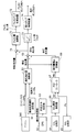
- FIG. 4 is a block diagram showing the configuration of the seawater amount control system in the exhaust gas treatment system according to the present embodiment.
- this seawater amount control system includes a heavy oil sulfur concentration setter 60, a minimum seawater amount converter 61, a GPS 62, an emission ratio setter 63, a CO 2 analyzer 64, and an SO 2 analysis.
- a total 65, an SO 2 concentration converter 66, a PID controller 67, a seawater amount correction converter 68, an addition element 69, and a pump control device 70 are provided.
- the seawater volume control system supplies the set seawater volume to the scrubber 10 by adding the minimum seawater volume converter 61 that calculates the minimum seawater volume, the seawater volume correction converter 68 that calculates the corrected seawater volume, and these. And a pump control device 70 that controls the seawater pump unit 30 (see FIG. 1).
- the minimum seawater amount converter 61 receives the output value of the engine 20 and the set value of the heavy oil sulfur concentration setter 60.
- the output value of the engine 20 is the output of the marine engine (from 0% to 100%).
- the set value of the heavy oil sulfur concentration setter 60 is the sulfur content (0% to 5%) of the fuel oil (heavy oil) used by the ship.
- the minimum seawater amount converter 61 is input with relation data between the output of the engine 20 operated in advance and the heavy oil consumption. When the output value of the engine 20 is input, it is converted into the heavy oil consumption. Then, the minimum seawater amount converter 61 multiplies the heavy oil consumption, the sulfur content of heavy oil, which is the set value of the heavy oil sulfur concentration setter 60, and the conversion coefficient to calculate the minimum seawater amount.
- the minimum amount of seawater refers to the minimum amount of seawater required for the absorption reaction of sulfur dioxide (SO 2 ) by seawater, which is represented by the above formulas (1) to (3).
- the GPS 62 measures the current position of the ship and outputs operation sea area information based on this position to the discharge ratio setting unit 63.
- the emission ratio setting unit 63 outputs the emission ratio of sulfur dioxide (SO 2 ) in the sea area to the SO 2 concentration converter 66 on the basis of the signal from the GPS 62 or the manually input operation sea area information.
- the emission ratio is a numerical value determined by the sulfur content in the fuel. Further, the sulfur content in the fuel is confirmed by measuring the emission ratio of carbon dioxide (CO 2 ) and sulfur dioxide (SO 2 ) in the exhaust gas.
- CO 2 analyzer 64 measures the concentration of CO 2 contained in the treated exhaust gas discharged from the scrubber 10 to atmosphere (the outlet CO 2 concentration).
- the output value of the CO 2 analyzer 64 is input to the SO 2 concentration converter 66.
- the SO 2 concentration converter 66 multiplies the outlet CO 2 concentration (%) by the emission ratio to calculate the SO 2 concentration (ppm) to be purified, and further multiplies the safety factor by 0.8 to set the outlet SO 2 concentration. (SV) is calculated.
- the set value (SV) of the outlet SO 2 concentration is output from the SO 2 concentration converter 66 to the PID controller 67.
- the specified emission ratio is 4.3.
- the SO 2 concentration measured by the CO 2 analyzer 64 is 5%
- the SO 2 analyzer 65 measures the concentration of SO 2 contained in the treated exhaust gas exhausted from the scrubber 10 into the atmosphere (exit SO 2 concentration).
- the measured value (PV) of the outlet SO 2 concentration is output from the SO 2 analyzer 65 to the PID controller 67.
- the PID controller 67 performs a PID control calculation based on a deviation between the outlet SO 2 concentration setting value input as the SV value and the outlet SO 2 concentration measurement value input as the PV value, and calculates the manipulated variable (MV) to obtain the seawater amount. Output to the correction converter 68.
- the PID controller 67 has a function of switching between automatic and manual for the input or output of the SV value, PV value, and MV value. Thereby, for example, when an input cannot be obtained from the SO 2 analyzer 65 due to failure or maintenance, the automatic input can be switched to the manual input.
- the seawater amount correction converter 68 sets the operation amount (MV), which is the output of the PID controller 67, to a seawater amount correction value proportional to the minimum seawater amount, and calculates a corrected seawater amount. For example, when the minimum seawater amount calculated by the minimum seawater amount converter 61 is 100 t / h, the MV value is 100%, and the proportionality constant is 0.5, the seawater amount correction converter 68 uses the corrected seawater amount. 50 t / h is calculated. Note that the proportionality constant may be given as a variation value in relation to the minimum amount of seawater instead of a fixed value.
- the set seawater volume is calculated by adding the minimum seawater volume calculated by the minimum seawater volume converter 61 and the corrected seawater volume calculated by the seawater volume correction converter 68.
- the set amount of seawater calculated by the addition element 69 is input to the pump controller 70.
- the pump control device 70 controls the seawater pump unit 30 to supply the set amount of seawater to the scrubber 10.
- the actual amount of seawater supplied from the seawater pump unit 30 to the scrubber 10 can be measured by installing a flow meter in the seawater pump unit 30. In this case, feedback control may be performed by comparing the actual seawater amount measured by the pump control device 70 with the set seawater amount. However, even if the actual seawater amount supplied from the seawater pump unit 30 to the scrubber 10 is insufficient and the outlet SO 2 concentration in the scrubber 10 becomes high, the corrected seawater amount is increased by the PID controller 67 in the seawater amount control system. Work in the direction.
- the pump for supplying seawater to the scrubber 10 may be singular or plural.
- the pump controller 70 increases the number of pumps to be operated as the set amount of seawater increases and the number of pumps to be decreased as the set amount of seawater decreases. It is good to control.
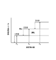
- FIG. 5 is a diagram showing the relationship between the number of pumps operated and the set amount of seawater when a plurality of pumps are provided.
- three pumps for supplying seawater to the scrubber 10 are provided, the solid line indicates the operation state of the pump, and the broken line indicates the stop state of the pump.
- only one pump is operated when the set amount of seawater is (F 1 ) to (F 2 ), and when the set amount of seawater exceeds (F 2 ), the second pump is also operated. Start driving. Further, when the set amount of seawater exceeds (F 3 ), the third pump also starts operation. When the set amount of seawater decreases below (F 3 ), the third pump stops operation, and when the set amount of seawater decreases below (F 2 ), the second pump also stops operation.
- the PID controller 67 in the seawater amount control system is limited to proportional control in order to avoid frequent repetition of the operation state and the stop state of the pumps. Therefore, it is necessary not to perform integral control.
- a plurality of pumps may be controlled by inverters in the pump control device 70.
- the pump can be controlled more finely than in the case where the control by the inverter is not performed.
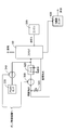
- FIG. 6 is a block diagram showing a configuration when the pump control device 70 includes an inverter.
- the pump control device 70 includes a pump flow rate setting device 70a, a first inverter 70b, and a second inverter. 70c.
- the pump flow rate setting unit 70a sets a flow rate for one pump.
- the first inverter 70 b controls the first pump 31, and the second inverter 70 c controls the second pump 32.
- FIG. 7 is a diagram showing the relationship between the flow rate setting value per pump and the set seawater amount according to the configuration shown in FIG.
- the solid line indicates the operation state of the pump
- the broken line indicates the stop state of the pump.
- the flow rate set values in the first pump 31 and the second pump 32 also decrease.
- the second pump 32 stops operating. Then, as the operation of the second pump 32 stops, the flow rate setting value of the first pump 31 increases.
- the control of a plurality of pumps by the inverter as shown in FIGS. 6 and 7 is to set a wide range of possible values of the set seawater amount, that is, to set a wide range of engine load fluctuation and a range of sulfur content of fuel oil. It is effective in some cases.
- each setting device, converter, and PID controller 67 shown in FIG. 4 may be configured by a combination of individual devices, or may be configured by a programmable logic controller (PLC).
- PLC programmable logic controller
- the alkali component necessary for neutralization of sulfur oxides (especially sulfur dioxide (SO 2 )) contained in the consumed heavy oil is minimized based on the engine output and the sulfur content of the heavy oil used.
- Calculated as the amount of seawater and further calculates the corrected seawater amount so that the sulfur oxide concentration contained in the treated exhaust gas exhausted from the scrubber 10 into the atmosphere does not exceed the emission regulation value, and adds these together
- the amount of seawater is controlled to be supplied to the scrubber 10.
- the amount of seawater supplied to the scrubber 10 does not become excessive or insufficient, and the amount of seawater appropriate for the scrubber is such that the sulfur oxide concentration in the exhaust gas after treatment does not exceed the regulation value. Can be operated stably.
- FIG. 8 is a schematic diagram showing an exhaust gas treatment system centered on a scrubber according to the second embodiment.
- the exhaust gas treatment system includes a scrubber 10 to which exhaust gas is supplied from the engine 200, a seawater pump 300 that supplies seawater to the scrubber 10, and a filter unit 400 that filters the wastewater discharged from the scrubber 10. And mainly consists of.
- the scrubber 10 is configured to be able to supply circulating seawater obtained by circulating seawater used for cleaning and fresh seawater not used for cleaning.
- the exhaust gas discharged from the engine 200 is introduced into the scrubber 10.
- This exhaust gas contains 50 to 1500 ppm of sulfur dioxide (SO 2 ).
- SO 2 sulfur dioxide
- the seawater introduced into the scrubber 10 is sprayed through the seawater pump 300 to make gas-liquid contact.
- the exhaust gas from which the reaction has been performed and sulfur dioxide (SO 2 ) has been removed as shown in the formulas (1) to (3) in the first embodiment is exhausted from the top of the scrubber 10 to the atmosphere.
- the seawater sprayed in the scrubber 10 falls by its own weight along the inner wall surface of the scrubber 10 and is stored in a storage section below the scrubber 10.
- the stored seawater is drained from the scrubber 10, then filtered by the filter unit 400 and drained to the ocean.
- the seawater stored in the scrubber 10 may not be drained into the ocean due to regulations.
- the seawater stored in the storage part of the scrubber 10 or a tank provided separately is supplied again to the seawater pump 300 via the circulation amount control valve 310, and used for exhaust gas treatment in the scrubber 10.
- the circulation amount control valve 310 is configured to supply only fresh seawater to the seawater pump 300 when fully closed, and supply only circulating seawater to the seawater pump 300 when fully opened.
- the valve opening degree of the circulation amount control valve 310 is set according to the amount of drainage allowed in the operating sea area. The amount of drainage may be calculated from a previously obtained valve opening and seawater pumping capacity, or may be measured by installing a flow meter at the inlet of fresh seawater.
- the temperature of the circulating seawater is increased by the heat of the absorbed exhaust gas. Therefore, the circulating seawater supplied from the scrubber 10 to the seawater pump 300 via the circulation amount control valve 310 is cooled by the cooling water in the heat exchanger 320 and then supplied to the scrubber 10 again.
- the circulating seawater consumes alkali components in the seawater by absorbing sulfur dioxide (SO 2 ) in the scrubber 10.
- SO 2 sulfur dioxide
- the alkaline component in seawater is insufficient, the absorption reaction of sulfur dioxide (SO 2 ) in the exhaust gas by seawater is inhibited, and sulfur dioxide contained in the treated exhaust gas exhausted from the scrubber 10 to the atmosphere ( The SO 2 ) concentration may exceed the emission regulation value.
- the circulating seawater supplied from the scrubber 10 to the seawater pump 300 via the circulation amount control valve 310 is supplied to the scrubber 10 again after an alkaline agent is injected from the alkali tank 330 via the alkali pump 340. Details of the alkali amount control at this time will be described later.
- the alkali agent a caustic soda (NaOH) solution can be used.
- the configuration of the scrubber 10 is the same as that of the scrubber 10 of the first embodiment except that the spray device 12 shown in FIG. 2 is connected to the seawater pump 300 and the gas supply device 13 is connected to the engine 200. Therefore, illustration explanation is omitted.
- the removal rate of sulfur dioxide (SO 2 ) improves as the amount of seawater supplied to the scrubber 10 is increased and the amount of seawater sprayed by the spray device 12 is increased. This is because the surface area of the droplets is increased by increasing the amount of seawater to be sprayed, the contact area between the exhaust gas and seawater is increased, and the total amount of alkali components contained in the seawater is increased.
- FIG. 9 is a block diagram showing a configuration of an alkali amount control system in the exhaust gas treatment system according to the present embodiment.
- this alkali amount control system includes a heavy oil sulfur concentration setting device 60, a minimum seawater amount converter 61, a GPS 62, an emission ratio setting device 63, and the like as in the first embodiment.
- a heavy oil sulfur concentration setting device 60 In addition to the CO 2 analyzer 64, the SO 2 analyzer 65, the SO 2 concentration converter 66, the PID controller 67, the seawater amount correction converter 68, and the addition element 69, the addition / subtraction element 75 and the alkali amount calculation
- a vessel 71, an alkali pump control device 72, an upper and lower limiter 73, and a seawater pump control device 74 are provided.
- the alkali control system includes a minimum seawater amount converter 61 for calculating the minimum seawater amount, a seawater amount correction converter 68 for calculating the corrected seawater amount, and a difference between the set seawater amount and the fresh seawater amount obtained by adding these. And an alkali amount calculator 71 that calculates an alkali injection amount for the circulating seawater based on the amount.
- the set seawater volume is calculated by adding the minimum seawater volume calculated by the minimum seawater volume converter 61 and the corrected seawater volume calculated by the seawater volume correction converter 68.
- the addition / subtraction element 75 the difference seawater amount obtained by subtracting the fresh seawater amount from the set seawater amount is calculated.
- the amount of seawater calculated by the addition / subtraction element 75 is input to the alkali amount calculator 71.
- the alkali amount calculator 71 outputs the calculated alkali injection amount to the alkali pump control device 72.
- the alkali pump control device 72 controls the alkali pump 340 to inject the alkali agent for the amount of alkali injection into the circulating seawater supplied to the scrubber 10.
- the set seawater amount calculated in the addition element 69 is input to the upper / lower limiter 73.
- the upper / lower limiter 73 determines the upper / lower limit value of the amount of seawater supplied to the scrubber 10 via the seawater pump 300. If the input set seawater amount exceeds the upper limit limiter, the upper limiter The value is output as the amount of seawater supplied to the scrubber 10. Similarly, when the input set seawater amount exceeds the lower limit value, the upper and lower limiter 73 outputs the lower limit value as the amount of seawater supplied to the scrubber 10. That is, the upper / lower limiter 73 regulates the amount of seawater supplied to the scrubber 10 within the upper / lower limit value range.
- the alkali component used for absorption and removal of sulfur dioxide (SO 2 ) in the exhaust gas does not depend only on the alkali component in seawater, and an alkali agent can be injected separately, so the amount of seawater supplied to the scrubber 10 is
- the amount of sulfur dioxide (SO 2 ) in the exhaust gas can be absorbed and removed by the contact between the exhaust gas and seawater, not the amount that compensates for the alkali component. Therefore, when the set amount of seawater exceeds the amount of seawater that can absorb and remove sulfur dioxide (SO 2 ) in the exhaust gas due to contact between the exhaust gas and seawater, the amount of seawater is supplied to the scrubber 10 as an upper limit value. Set as the amount of seawater to be used.
- the amount of alkali supplied to the scrubber 10 needs to be injected according to the amount of sulfur dioxide (SO 2 ) to be treated. If the amount of alkali is insufficient, the concentration of sulfur dioxide (SO 2 ) in the exhaust gas exceeds the regulation value, which is a problem. It becomes. Therefore, the upper limit / lower limiter 73 determines the upper limit value and the lower limit value of the amount of seawater supplied to the scrubber 10, thereby reducing the power of the seawater pump 300 and reducing the set seawater amount calculated by the addition element 69 and the freshness. Since the amount of alkali is supplied in proportion to the difference from the amount of seawater, an appropriate amount of alkali can be supplied to the scrubber 10 and stable operation can be achieved.
- the amount of seawater set by the upper / lower limiter 73 is input to the seawater pump control device 74.
- the seawater pump control device 74 controls the seawater pump 300 to supply seawater equivalent to the amount of seawater to the scrubber 10.
- the actual amount of seawater supplied from the seawater pump 300 to the scrubber 10 can be measured by installing a flow meter in the seawater pump 300.
- feedback control may be performed by comparing the actual seawater amount measured by the seawater pump control device 74 with the set seawater amount.
- the corrected seawater amount is increased by the PID controller 67 in the alkali amount control system. In order to work, the amount of alkali injection increases.
- the pump for supplying seawater to the scrubber 10 may be singular or plural.
- the seawater pump control device 74 causes the plurality of pumps to increase the number of operating pumps as the set amount of seawater increases and reduce the number of operating pumps as the set amount of seawater decreases. May be controlled (see FIG. 5).
- the PID controller 67 in the alkali amount control system is limited to proportional control in order to avoid frequent repetition of the operation state and the stop state of the pumps. Therefore, it is necessary not to perform integral control.
- a plurality of pumps may be controlled by an inverter in the seawater pump control device 74.
- the pump can be controlled more finely than in the case where the control by the inverter is not performed.
- FIG. 10 is a block diagram showing a configuration when the seawater pump control device 74 includes an inverter.
- the seawater pump control device 74 includes a pump flow rate setting device 74a, a first inverter 74b, And an inverter 74c.
- the pump flow rate setting unit 74a sets a flow rate for one pump.
- the first inverter 74b controls the first pump 300a
- the second inverter 74c controls the second pump 300b.
- FIG. 11 is a diagram showing the relationship between the flow rate setting value per pump and the set seawater amount according to the configuration shown in FIG. In FIG. 11, the solid line indicates the operation state of the pump, and the broken line indicates the stop state of the pump.
- the flow rate set values in the first pump 300a and the second pump 300b also decrease.
- the second pump 300b stops operation. Then, as the operation of the second pump 300b is stopped, the flow rate set value of the first pump 300a increases.
- sulfur oxide particularly, sulfur dioxide (SO 2 ) contained in consumed heavy oil from the engine output and the sulfur content of heavy oil to be used.
- Is calculated, and the alkali injection amount to be injected into the seawater is calculated based on the set seawater amount obtained by adding these together.
- the concentration of sulfur dioxide (SO 2 ) in the exhaust gas is within the regulation value, and that carbon dioxide (CO 2 ) and sulfur dioxide ( The concentration of SO 2 ) is controlled by measuring with a CO 2 analyzer 64 and an SO 2 analyzer 65, respectively. According to these analyzers, stable measurement results can be obtained from the pH meter. Therefore, by calculating the amount of alkali injected into seawater based on the measurement results of these analyzers, stable and reliable sulfur oxidation It is possible to obtain a removal rate of objects.
Landscapes
- Engineering & Computer Science (AREA)
- Chemical & Material Sciences (AREA)
- General Chemical & Material Sciences (AREA)
- Chemical Kinetics & Catalysis (AREA)
- Oil, Petroleum & Natural Gas (AREA)
- Analytical Chemistry (AREA)
- Automation & Control Theory (AREA)
- Physics & Mathematics (AREA)
- General Physics & Mathematics (AREA)
- Health & Medical Sciences (AREA)
- Biomedical Technology (AREA)
- Environmental & Geological Engineering (AREA)
- Treating Waste Gases (AREA)
- Exhaust Gas After Treatment (AREA)
- Gas Separation By Absorption (AREA)
Abstract
Priority Applications (7)
| Application Number | Priority Date | Filing Date | Title |
|---|---|---|---|
| DK14746808.6T DK2952243T3 (en) | 2013-01-29 | 2014-01-27 | Seawater flow control device for a scrubber, method for controlling the seawater flow rate for a scrubber, alkali flow control device and method for controlling the amount of alkali |
| CN201480002644.2A CN104736225B (zh) | 2013-01-29 | 2014-01-27 | 气体洗涤器的海水量控制装置、气体洗涤器的海水量控制方法、碱量控制装置及碱量控制方法 |
| KR1020157008817A KR101740665B1 (ko) | 2013-01-29 | 2014-01-27 | 스크러버의 해수량 제어 장치, 스크러버의 해수량 제어 방법, 알칼리량 제어 장치 및 알칼리량 제어 방법 |
| JP2014559666A JP5958563B2 (ja) | 2013-01-29 | 2014-01-27 | スクラバの海水量制御装置、スクラバの海水量制御方法、アルカリ量制御装置及びアルカリ量制御方法 |
| EP14746808.6A EP2952243B1 (fr) | 2013-01-29 | 2014-01-27 | Dispositif de commande de quantité d'eau de mer pour laveur de gaz, procédé de commande de quantité d'eau de mer pour laveur de gaz, dispositif de commande de quantité d'alcali, et procédé de commande de quantité d'alcali |
| US14/680,047 US10150078B2 (en) | 2013-01-29 | 2015-04-06 | Amount of seawater control device for scrubber, amount of seawater control method for scrubber, and amount of alkali control device and amount of alkali control method |
| US16/193,052 US20190083924A1 (en) | 2013-01-29 | 2018-11-16 | Amount of seawater control device for scrubber, amount of seawater control method for scrubber, and amount of alkali control device and amount of alkali control method |
Applications Claiming Priority (4)
| Application Number | Priority Date | Filing Date | Title |
|---|---|---|---|
| JP2013014316 | 2013-01-29 | ||
| JP2013-014316 | 2013-01-29 | ||
| JP2013-014317 | 2013-01-29 | ||
| JP2013014317 | 2013-01-29 |
Related Child Applications (1)
| Application Number | Title | Priority Date | Filing Date |
|---|---|---|---|
| US14/680,047 Continuation US10150078B2 (en) | 2013-01-29 | 2015-04-06 | Amount of seawater control device for scrubber, amount of seawater control method for scrubber, and amount of alkali control device and amount of alkali control method |
Publications (1)
| Publication Number | Publication Date |
|---|---|
| WO2014119513A1 true WO2014119513A1 (fr) | 2014-08-07 |
Family
ID=51262228
Family Applications (1)
| Application Number | Title | Priority Date | Filing Date |
|---|---|---|---|
| PCT/JP2014/051672 WO2014119513A1 (fr) | 2013-01-29 | 2014-01-27 | Dispositif de commande de quantité d'eau de mer pour épurateur, procédé de commande de quantité d'eau de mer pour épurateur, dispositif de commande de quantité d'alcali, et procédé de commande de quantité d'alcali |
Country Status (7)
| Country | Link |
|---|---|
| US (2) | US10150078B2 (fr) |
| EP (1) | EP2952243B1 (fr) |
| JP (1) | JP5958563B2 (fr) |
| KR (1) | KR101740665B1 (fr) |
| CN (1) | CN104736225B (fr) |
| DK (1) | DK2952243T3 (fr) |
| WO (1) | WO2014119513A1 (fr) |
Cited By (12)
| Publication number | Priority date | Publication date | Assignee | Title |
|---|---|---|---|---|
| WO2016009549A1 (fr) * | 2014-07-18 | 2016-01-21 | 富士電機株式会社 | Appareil et procédé de commande de quantité d'eau de mer pour épurateur et appareil de commande de quantité d'alcali |
| JP5910798B2 (ja) * | 2013-10-17 | 2016-04-27 | 富士電機株式会社 | ガス吸収塔、ガス吸収塔の製造方法及び船舶 |
| JP5910785B1 (ja) * | 2015-09-14 | 2016-04-27 | 富士電機株式会社 | 排ガス処理装置および排ガス処理装置のメンテナンス方法 |
| JP5910789B1 (ja) * | 2015-11-17 | 2016-04-27 | 富士電機株式会社 | 排ガス処理装置および幹管の分割体を吸収塔から取り出す方法 |
| JP2016109134A (ja) * | 2014-12-03 | 2016-06-20 | エム アー エヌ トラック アンド バス アクチエンゲゼルシヤフトMAN Truck & Bus AG | 乗物、例えば水上乗物、を動作させる方法および装置 |
| WO2016147741A1 (fr) * | 2015-03-16 | 2016-09-22 | 富士電機株式会社 | DISPOSITIF ET PROCÉDÉ DE CALCUL DE pH |
| US20170001143A1 (en) * | 2014-09-02 | 2017-01-05 | Fuji Electric Co., Ltd. | Exhaust gas treatment device and waste water treatment method for exhaust gas treatment device |
| JP2018507779A (ja) * | 2015-03-04 | 2018-03-22 | サムスン・ヘヴィー・インダストリーズ・カンパニー・リミテッド | 汚染物質低減装置及び方法 |
| US10150078B2 (en) | 2013-01-29 | 2018-12-11 | Fuji Electric Co., Ltd. | Amount of seawater control device for scrubber, amount of seawater control method for scrubber, and amount of alkali control device and amount of alkali control method |
| JP2020501058A (ja) * | 2016-10-28 | 2020-01-16 | ヤラ マリン テクノロジーズ エーエスYara Marine Technologies As | 船舶の排出ガス浄化システムの排出ガス導入口における洗浄液の流量を決定するシステムと方法 |
| JP2022179349A (ja) * | 2021-05-21 | 2022-12-02 | 華能国際電力股▲ふん▼有限公司大連電廠 | 海水脱硫制御方法と装置 |
| KR20230044491A (ko) | 2021-03-23 | 2023-04-04 | 후지 덴키 가부시키가이샤 | 배기가스 처리 장치 및 배기가스 처리 방법 |
Families Citing this family (13)
| Publication number | Priority date | Publication date | Assignee | Title |
|---|---|---|---|---|
| KR101664745B1 (ko) | 2015-09-25 | 2016-10-24 | 현대자동차주식회사 | 배터리의 릴레이 융착 검출 방법 |
| MX2017008528A (es) | 2017-06-14 | 2019-02-08 | Jiangnan Environmental Prot Group Inc | Sistema y método de adición automatica de amoniaco para dispositivo de desulfuración basado en amoniaco. |
| US10696906B2 (en) | 2017-09-29 | 2020-06-30 | Marathon Petroleum Company Lp | Tower bottoms coke catching device |
| US11975316B2 (en) | 2019-05-09 | 2024-05-07 | Marathon Petroleum Company Lp | Methods and reforming systems for re-dispersing platinum on reforming catalyst |
| CN110302642A (zh) * | 2019-06-26 | 2019-10-08 | 青岛双瑞海洋环境工程股份有限公司 | 船舶废气脱硫系统的控制方法 |
| CN110368815B (zh) * | 2019-08-05 | 2022-03-25 | 中船动力研究院有限公司 | 钠碱脱硫控制方法、控制装置及脱硫系统 |
| US11352578B2 (en) | 2020-02-19 | 2022-06-07 | Marathon Petroleum Company Lp | Low sulfur fuel oil blends for stabtility enhancement and associated methods |
| JP7375929B2 (ja) | 2020-05-27 | 2023-11-08 | 富士電機株式会社 | 船舶用排ガス処理装置 |
| US11905468B2 (en) | 2021-02-25 | 2024-02-20 | Marathon Petroleum Company Lp | Assemblies and methods for enhancing control of fluid catalytic cracking (FCC) processes using spectroscopic analyzers |
| US11898109B2 (en) | 2021-02-25 | 2024-02-13 | Marathon Petroleum Company Lp | Assemblies and methods for enhancing control of hydrotreating and fluid catalytic cracking (FCC) processes using spectroscopic analyzers |
| US20220268694A1 (en) | 2021-02-25 | 2022-08-25 | Marathon Petroleum Company Lp | Methods and assemblies for determining and using standardized spectral responses for calibration of spectroscopic analyzers |
| US11692141B2 (en) | 2021-10-10 | 2023-07-04 | Marathon Petroleum Company Lp | Methods and systems for enhancing processing of hydrocarbons in a fluid catalytic cracking unit using a renewable additive |
| CA3188122A1 (fr) | 2022-01-31 | 2023-07-31 | Marathon Petroleum Company Lp | Systemes et methodes de reduction des points d'ecoulement de gras fondus |
Citations (4)
| Publication number | Priority date | Publication date | Assignee | Title |
|---|---|---|---|---|
| JP2993891B2 (ja) | 1995-09-23 | 1999-12-27 | ルルギ、レントイェス、ビショッフ、ゲゼルシャフト、ミット、ベシュレンクテル、ハフツング | 廃ガスから二酸化硫黄を分離除去する方法 |
| JP2004081933A (ja) | 2002-08-23 | 2004-03-18 | Mitsubishi Heavy Ind Ltd | 排水処理装置 |
| JP2011524800A (ja) * | 2008-06-13 | 2011-09-08 | 斯幹 彭 | 航海船における排ガス脱硫方法および排ガス脱硫装置 |
| JP2012179521A (ja) * | 2011-02-28 | 2012-09-20 | Mitsubishi Heavy Ind Ltd | 海水排煙脱硫システムおよび発電システム |
Family Cites Families (12)
| Publication number | Priority date | Publication date | Assignee | Title |
|---|---|---|---|---|
| JPH03288523A (ja) | 1990-04-02 | 1991-12-18 | Toshiba Corp | 排煙脱流装置の制御装置 |
| JPH0861287A (ja) * | 1994-08-11 | 1996-03-08 | Ebara Corp | ポンプ用インバータユニット及びそのユニットを備えたポンプ装置 |
| DE29517697U1 (de) | 1995-07-29 | 1996-01-18 | Gottfried Bischoff Gmbh & Co | Rauchgasentschwefelungsanlage |
| JPH11244646A (ja) * | 1998-03-05 | 1999-09-14 | Ishikawajima Harima Heavy Ind Co Ltd | 排煙脱硫装置の吸収剤スラリー流量制御方法及び装置 |
| US6289988B1 (en) * | 2000-03-24 | 2001-09-18 | Exxonmobil Research And Engineering Company | Process for management of industrial wastes |
| JP4381064B2 (ja) * | 2003-08-26 | 2009-12-09 | 三菱重工業株式会社 | 排ガス処理装置および処理方法 |
| US8540493B2 (en) | 2003-12-08 | 2013-09-24 | Sta-Rite Industries, Llc | Pump control system and method |
| JP2007051555A (ja) | 2005-08-16 | 2007-03-01 | Mitsui Eng & Shipbuild Co Ltd | ディーゼルエンジンの排ガス浄化装置 |
| CN102363091A (zh) * | 2011-06-28 | 2012-02-29 | 顾忠华 | 船用尾排气处理系统的海水脱硫装置 |
| EP2574393A1 (fr) | 2011-09-30 | 2013-04-03 | Alfa Laval Aalborg A/S | Système de lavage et procédé |
| EP2952243B1 (fr) | 2013-01-29 | 2018-09-19 | Fuji Electric Co., Ltd. | Dispositif de commande de quantité d'eau de mer pour laveur de gaz, procédé de commande de quantité d'eau de mer pour laveur de gaz, dispositif de commande de quantité d'alcali, et procédé de commande de quantité d'alcali |
| JP5939366B1 (ja) | 2014-07-18 | 2016-06-22 | 富士電機株式会社 | スクラバの海水量制御装置、スクラバの海水量制御方法及びアルカリ量制御装置 |
-
2014
- 2014-01-27 EP EP14746808.6A patent/EP2952243B1/fr active Active
- 2014-01-27 WO PCT/JP2014/051672 patent/WO2014119513A1/fr active Application Filing
- 2014-01-27 CN CN201480002644.2A patent/CN104736225B/zh active Active
- 2014-01-27 KR KR1020157008817A patent/KR101740665B1/ko active IP Right Grant
- 2014-01-27 JP JP2014559666A patent/JP5958563B2/ja active Active
- 2014-01-27 DK DK14746808.6T patent/DK2952243T3/en active
-
2015
- 2015-04-06 US US14/680,047 patent/US10150078B2/en active Active
-
2018
- 2018-11-16 US US16/193,052 patent/US20190083924A1/en not_active Abandoned
Patent Citations (4)
| Publication number | Priority date | Publication date | Assignee | Title |
|---|---|---|---|---|
| JP2993891B2 (ja) | 1995-09-23 | 1999-12-27 | ルルギ、レントイェス、ビショッフ、ゲゼルシャフト、ミット、ベシュレンクテル、ハフツング | 廃ガスから二酸化硫黄を分離除去する方法 |
| JP2004081933A (ja) | 2002-08-23 | 2004-03-18 | Mitsubishi Heavy Ind Ltd | 排水処理装置 |
| JP2011524800A (ja) * | 2008-06-13 | 2011-09-08 | 斯幹 彭 | 航海船における排ガス脱硫方法および排ガス脱硫装置 |
| JP2012179521A (ja) * | 2011-02-28 | 2012-09-20 | Mitsubishi Heavy Ind Ltd | 海水排煙脱硫システムおよび発電システム |
Non-Patent Citations (1)
| Title |
|---|
| See also references of EP2952243A4 |
Cited By (27)
| Publication number | Priority date | Publication date | Assignee | Title |
|---|---|---|---|---|
| US10150078B2 (en) | 2013-01-29 | 2018-12-11 | Fuji Electric Co., Ltd. | Amount of seawater control device for scrubber, amount of seawater control method for scrubber, and amount of alkali control device and amount of alkali control method |
| JP5910798B2 (ja) * | 2013-10-17 | 2016-04-27 | 富士電機株式会社 | ガス吸収塔、ガス吸収塔の製造方法及び船舶 |
| JPWO2015056562A1 (ja) * | 2013-10-17 | 2017-03-09 | 富士電機株式会社 | ガス吸収塔、ガス吸収塔の製造方法及び船舶 |
| WO2016009549A1 (fr) * | 2014-07-18 | 2016-01-21 | 富士電機株式会社 | Appareil et procédé de commande de quantité d'eau de mer pour épurateur et appareil de commande de quantité d'alcali |
| US10099175B2 (en) | 2014-07-18 | 2018-10-16 | Fuji Electric Co., Ltd. | Amount-of-seawater control device for scrubber, amount-of-seawater control method for scrubber, and amount-of-alkali control device |
| US20170001143A1 (en) * | 2014-09-02 | 2017-01-05 | Fuji Electric Co., Ltd. | Exhaust gas treatment device and waste water treatment method for exhaust gas treatment device |
| US9821268B2 (en) * | 2014-09-02 | 2017-11-21 | Fuji Electric Co., Ltd. | Exhaust gas treatment device and waste water treatment method for exhaust gas treatment device |
| JP2016109134A (ja) * | 2014-12-03 | 2016-06-20 | エム アー エヌ トラック アンド バス アクチエンゲゼルシヤフトMAN Truck & Bus AG | 乗物、例えば水上乗物、を動作させる方法および装置 |
| US10618622B2 (en) | 2015-03-04 | 2020-04-14 | Samsung Heavy Industries Co., Ltd. | Pollutant reduction device and method |
| JP2018507779A (ja) * | 2015-03-04 | 2018-03-22 | サムスン・ヘヴィー・インダストリーズ・カンパニー・リミテッド | 汚染物質低減装置及び方法 |
| KR102086398B1 (ko) | 2015-03-16 | 2020-03-09 | 후지 덴키 가부시키가이샤 | 장치 및 pH의 산출 방법 |
| US10456733B2 (en) | 2015-03-16 | 2019-10-29 | Fuji Electric Co., Ltd. | Apparatus and calculating method of pH |
| CN107003292A (zh) * | 2015-03-16 | 2017-08-01 | 富士电机株式会社 | 装置及pH值的计算方法 |
| JPWO2016147741A1 (ja) * | 2015-03-16 | 2017-09-14 | 富士電機株式会社 | 装置およびpHの算出方法 |
| US11117089B2 (en) | 2015-03-16 | 2021-09-14 | Fuji Electric Co., Ltd. | Apparatus and calculating method of pH |
| KR20170128207A (ko) * | 2015-03-16 | 2017-11-22 | 후지 덴키 가부시키가이샤 | 장치 및 pH의 산출 방법 |
| WO2016147741A1 (fr) * | 2015-03-16 | 2016-09-22 | 富士電機株式会社 | DISPOSITIF ET PROCÉDÉ DE CALCUL DE pH |
| JP5910785B1 (ja) * | 2015-09-14 | 2016-04-27 | 富士電機株式会社 | 排ガス処理装置および排ガス処理装置のメンテナンス方法 |
| WO2017047292A1 (fr) * | 2015-09-14 | 2017-03-23 | 富士電機株式会社 | Dispositif de traitement de gaz d'échappement et procédé de maintenance pour le dispositif de traitement de gaz d'échappement |
| JP2017056385A (ja) * | 2015-09-14 | 2017-03-23 | 富士電機株式会社 | 排ガス処理装置および排ガス処理装置のメンテナンス方法 |
| JP5910789B1 (ja) * | 2015-11-17 | 2016-04-27 | 富士電機株式会社 | 排ガス処理装置および幹管の分割体を吸収塔から取り出す方法 |
| WO2017086024A1 (fr) * | 2015-11-17 | 2017-05-26 | 富士電機株式会社 | Dispositif et procédé de traitement de gaz d'échappement pour extraction de segment de tuyau de tige d'une colonne d'absorption |
| JP2017087193A (ja) * | 2015-11-17 | 2017-05-25 | 富士電機株式会社 | 排ガス処理装置および幹管の分割体を吸収塔から取り出す方法 |
| JP2020501058A (ja) * | 2016-10-28 | 2020-01-16 | ヤラ マリン テクノロジーズ エーエスYara Marine Technologies As | 船舶の排出ガス浄化システムの排出ガス導入口における洗浄液の流量を決定するシステムと方法 |
| JP7022122B2 (ja) | 2016-10-28 | 2022-02-17 | ヤラ マリン テクノロジーズ エーエス | 船舶の排出ガス浄化ユニットにおける洗浄液の流量を決定するシステムと方法 |
| KR20230044491A (ko) | 2021-03-23 | 2023-04-04 | 후지 덴키 가부시키가이샤 | 배기가스 처리 장치 및 배기가스 처리 방법 |
| JP2022179349A (ja) * | 2021-05-21 | 2022-12-02 | 華能国際電力股▲ふん▼有限公司大連電廠 | 海水脱硫制御方法と装置 |
Also Published As
| Publication number | Publication date |
|---|---|
| CN104736225B (zh) | 2018-05-04 |
| JPWO2014119513A1 (ja) | 2017-01-26 |
| EP2952243A4 (fr) | 2016-08-31 |
| KR101740665B1 (ko) | 2017-05-26 |
| KR20150110459A (ko) | 2015-10-02 |
| US10150078B2 (en) | 2018-12-11 |
| EP2952243B1 (fr) | 2018-09-19 |
| US20150209720A1 (en) | 2015-07-30 |
| DK2952243T3 (en) | 2019-01-14 |
| JP5958563B2 (ja) | 2016-08-02 |
| US20190083924A1 (en) | 2019-03-21 |
| EP2952243A1 (fr) | 2015-12-09 |
| CN104736225A (zh) | 2015-06-24 |
Similar Documents
| Publication | Publication Date | Title |
|---|---|---|
| JP5958563B2 (ja) | スクラバの海水量制御装置、スクラバの海水量制御方法、アルカリ量制御装置及びアルカリ量制御方法 | |
| JP5939366B1 (ja) | スクラバの海水量制御装置、スクラバの海水量制御方法及びアルカリ量制御装置 | |
| US9550145B2 (en) | Exhaust gas treatment apparatus, ship, and exhaust gas treatment method | |
| KR102047196B1 (ko) | 습식 배연 탈황 장치 및 습식 배연 탈황 장치의 운전 방법 | |
| KR20140073279A (ko) | 선박용 배기 가스 정화장치 | |
| WO2016208273A1 (fr) | Appareil de traitement de gaz d'échappement | |
| KR20150075663A (ko) | 선박용 배기가스 정화 시스템 및 배기가스 정화 방법 | |
| KR20140073280A (ko) | 선박용 배기 가스 정화장치 | |
| JP7310920B2 (ja) | 排ガス処理装置 | |
| KR102334645B1 (ko) | 배기 및 배수 오염물질 저감장치 | |
| CN212974627U (zh) | 一种船舶用废气处理装置 | |
| JP7357331B2 (ja) | スクラバ装置、及びスクラバ装置を搭載した船舶 | |
| CN208145738U (zh) | 一种氧化还原法治理氮氧化物废气的处理设备 | |
| KR20220113536A (ko) | 배기가스 정화 장치 | |
| KR20220135295A (ko) | 선박용 탈황 스크러버를 이용한 이산화탄소 저감장치 | |
| KR20220137774A (ko) | 배출 가스 처리 장치 및 배출 가스 처리 장치의 배출 가스 처리 방법 | |
| KR20220119480A (ko) | 배기 가스 정화 장치 | |
| CN107875817A (zh) | 一种等离子脱硝装置 | |
| JP2011194296A (ja) | 排煙脱硫装置 |
Legal Events
| Date | Code | Title | Description |
|---|---|---|---|
| 121 | Ep: the epo has been informed by wipo that ep was designated in this application |
Ref document number: 14746808 Country of ref document: EP Kind code of ref document: A1 |
|
| WWE | Wipo information: entry into national phase |
Ref document number: 2014746808 Country of ref document: EP |
|
| ENP | Entry into the national phase |
Ref document number: 20157008817 Country of ref document: KR Kind code of ref document: A |
|
| ENP | Entry into the national phase |
Ref document number: 2014559666 Country of ref document: JP Kind code of ref document: A |
|
| NENP | Non-entry into the national phase |
Ref country code: DE |