WO2014118872A1 - Système de surveillance - Google Patents
Système de surveillance Download PDFInfo
- Publication number
- WO2014118872A1 WO2014118872A1 PCT/JP2013/051822 JP2013051822W WO2014118872A1 WO 2014118872 A1 WO2014118872 A1 WO 2014118872A1 JP 2013051822 W JP2013051822 W JP 2013051822W WO 2014118872 A1 WO2014118872 A1 WO 2014118872A1
- Authority
- WO
- WIPO (PCT)
- Prior art keywords
- information
- area
- information storage
- predetermined
- monitoring system
- Prior art date
Links
Images


Classifications
-
- G—PHYSICS
- G06—COMPUTING; CALCULATING OR COUNTING
- G06T—IMAGE DATA PROCESSING OR GENERATION, IN GENERAL
- G06T7/00—Image analysis
- G06T7/10—Segmentation; Edge detection
- G06T7/11—Region-based segmentation
-
- G—PHYSICS
- G08—SIGNALLING
- G08B—SIGNALLING OR CALLING SYSTEMS; ORDER TELEGRAPHS; ALARM SYSTEMS
- G08B13/00—Burglar, theft or intruder alarms
- G08B13/18—Actuation by interference with heat, light, or radiation of shorter wavelength; Actuation by intruding sources of heat, light, or radiation of shorter wavelength
- G08B13/189—Actuation by interference with heat, light, or radiation of shorter wavelength; Actuation by intruding sources of heat, light, or radiation of shorter wavelength using passive radiation detection systems
- G08B13/194—Actuation by interference with heat, light, or radiation of shorter wavelength; Actuation by intruding sources of heat, light, or radiation of shorter wavelength using passive radiation detection systems using image scanning and comparing systems
- G08B13/196—Actuation by interference with heat, light, or radiation of shorter wavelength; Actuation by intruding sources of heat, light, or radiation of shorter wavelength using passive radiation detection systems using image scanning and comparing systems using television cameras
- G08B13/19639—Details of the system layout
- G08B13/19652—Systems using zones in a single scene defined for different treatment, e.g. outer zone gives pre-alarm, inner zone gives alarm
-
- G—PHYSICS
- G06—COMPUTING; CALCULATING OR COUNTING
- G06T—IMAGE DATA PROCESSING OR GENERATION, IN GENERAL
- G06T7/00—Image analysis
- G06T7/70—Determining position or orientation of objects or cameras
- G06T7/73—Determining position or orientation of objects or cameras using feature-based methods
-
- G—PHYSICS
- G06—COMPUTING; CALCULATING OR COUNTING
- G06V—IMAGE OR VIDEO RECOGNITION OR UNDERSTANDING
- G06V10/00—Arrangements for image or video recognition or understanding
- G06V10/20—Image preprocessing
- G06V10/255—Detecting or recognising potential candidate objects based on visual cues, e.g. shapes
-
- G—PHYSICS
- G06—COMPUTING; CALCULATING OR COUNTING
- G06V—IMAGE OR VIDEO RECOGNITION OR UNDERSTANDING
- G06V20/00—Scenes; Scene-specific elements
- G06V20/50—Context or environment of the image
- G06V20/52—Surveillance or monitoring of activities, e.g. for recognising suspicious objects
-
- G—PHYSICS
- G06—COMPUTING; CALCULATING OR COUNTING
- G06V—IMAGE OR VIDEO RECOGNITION OR UNDERSTANDING
- G06V40/00—Recognition of biometric, human-related or animal-related patterns in image or video data
- G06V40/10—Human or animal bodies, e.g. vehicle occupants or pedestrians; Body parts, e.g. hands
-
- H—ELECTRICITY
- H04—ELECTRIC COMMUNICATION TECHNIQUE
- H04N—PICTORIAL COMMUNICATION, e.g. TELEVISION
- H04N23/00—Cameras or camera modules comprising electronic image sensors; Control thereof
- H04N23/80—Camera processing pipelines; Components thereof
-
- G—PHYSICS
- G06—COMPUTING; CALCULATING OR COUNTING
- G06T—IMAGE DATA PROCESSING OR GENERATION, IN GENERAL
- G06T2207/00—Indexing scheme for image analysis or image enhancement
- G06T2207/10—Image acquisition modality
- G06T2207/10004—Still image; Photographic image
-
- G—PHYSICS
- G06—COMPUTING; CALCULATING OR COUNTING
- G06T—IMAGE DATA PROCESSING OR GENERATION, IN GENERAL
- G06T2207/00—Indexing scheme for image analysis or image enhancement
- G06T2207/30—Subject of image; Context of image processing
- G06T2207/30232—Surveillance
Definitions
- the present invention relates to a monitoring system. Specifically, the present invention relates to a monitoring system that can efficiently detect a target to be monitored from an image.
- the camera may be installed in a building such as a station or a store, or an outdoor gate or an outer wall.
- a monitoring system generally includes a camera that captures images, a monitor that displays the captured images, and a notification means that informs the monitor that an emergency has occurred with an alarm or signal when a suspicious person is detected. Have.
- monitoring system that can be used by the monitor without always checking the video on the monitor.
- This monitoring system has a mechanism for notifying by a warning only when a suspicious person is detected, reducing the burden on the monitoring person and reducing the number of manpower required for monitoring.
- one of the problems of the monitoring system that has a mechanism for detecting a suspicious person and notifying with an alarm is that the object to be detected is erroneously recognized and the alarm is activated. It detects even people who do not want to be detected as suspicious persons, such as security guards, and sounds an alarm. If the alarm is activated frequently, the supervisor will need to check the video and the site each time. This is a burden on the observer and is not easy to use as a monitoring system.
- Patent Document 1 describes a monitoring system 100 as shown in FIG.
- the monitoring system 100 includes a monitoring control device 101, a monitoring camera 102, and a notification exclusion signal output device 103 to be given to a subject who does not want to detect.
- the notification exclusion signal output device 103 blinks the light source 104 according to the notification exclusion pattern, and the monitoring control device 101 recognizes the moving object having the light emission of the light source 104 as a notification exclusion person.
- the person excluded from the detection target is limited to the person having the notification exclusion signal output device. That is, it can be said that it is an effective monitoring system if it is a space limited to only a specific person.
- the alarm is frequently activated in a place where other persons are supposed to come and go, for example, in a parking lot used by ordinary people.
- the whole image of the suspicious person is not reflected and can be detected, but there is a problem that a clear image cannot be acquired.
- the detection target is human
- the outline is unclear and the shape cannot be accurately determined.
- the present invention has been made in view of the above points, and an object thereof is to provide a monitoring system capable of efficiently detecting an object to be monitored from an image.
- a monitoring system includes monitoring area storage means for storing a monitoring area, which is a part of an imaging area, and at least a part of an object in an input video. Is determined to be located within the monitoring area stored in the monitoring area storage means, and when it is determined that at least a part of the object is located within the monitoring area, the object is set to a predetermined condition.
- Video analysis means configured to determine whether or not the above condition is satisfied.
- a specific area in the imaging area can be stored as the monitoring area by having monitoring area storage means for storing a monitoring area that is a partial area in the imaging area.
- the imaging region means an image of a region to be monitored captured by a camera.
- the image analysis means for determining whether or not at least a part of the object in the input video is located in the monitoring area stored in the monitoring area storage means, so that a part of the object is monitored area It can be determined whether or not it is located inside.
- the object is excluded from the target to be detected. That is, the determination of whether or not it is located within the monitoring area is the first step for specifying the detection target.
- the efficiency of detection can be improved by excluding objects that are not located in the monitoring area as unnecessary information.
- the object when it is determined that at least a part of the object is located within the monitoring area, the object is monitored by having image analysis means configured to determine whether the object satisfies a predetermined condition. It is possible to determine whether or not the object satisfies a predetermined condition only for an object that falls within the region. That is, the detection target can be specified by determining in the second step whether or not an object that has been determined in the first step of being located in the monitoring region meets a predetermined condition.
- the image analysis means configured to determine whether or not the object satisfies a predetermined condition, two different determination target areas It is possible to specify the detection target. That is, in the first step, the determination is made only in the monitoring area, whereas in the second step, the determination is made with the whole image of the object that has entered the imaging area. In the second step, it is possible to confirm the whole image including the part located outside the monitoring area of the object, and solve the problem that even if the object is detected, only the unclear shape only in the monitoring area can be confirmed. be able to.
- the image analysis means configured to determine whether or not the object satisfies a predetermined condition can be used as a detection target with the two determination criteria of the first step and the second step. It can be determined whether or not there is. Since different criteria are set in each step, the detection efficiency can be increased.
- the first step is within the monitoring area, and the second step is different from the overall image of the object entering the imaging area and the determination target area. Can be increased.
- the detection efficiency can be further increased.
- an effective area storage unit that stores a predetermined area in the imaging area and an area that at least partially overlaps the monitoring area as an effective area
- a specific range in the imaging area is effective. It can be stored as an area.
- the “effective area” means an area where only an object falling within the range can be detected as a detection target.
- an object that does not fall within the effective area is excluded from the detection target.
- the determination in the second step is based on the effective area. Will be done. That is, if the object that has undergone the determination in the first step is included within the range of the stored effective area, it can be specified as a detection target. In addition, by setting an effective region in which an object desired to be detected falls within the range, an object larger than that can be excluded from the detection target, and the accuracy of determination as to whether or not the object is a detection target can be improved.
- object reference information storage means for storing at least one of the upper limit or lower limit information of the object shape as object reference information
- the upper and lower limits of the object shape are set and stored as object reference information. be able to.
- the video analysis unit determines whether the shape of the object corresponds to the upper limit or lower limit of the object reference information stored in the object reference information storage unit as the predetermined condition
- the step is determined based on the object reference information. That is, when only the upper limit is set, it can be determined whether the shape of the object is greater than or equal to the set upper limit or less than the upper limit, and whether or not the object is a detection target can be specified. Further, when only the lower limit is set, it can be determined whether it is equal to or higher than the lower limit or lower than the lower limit, and whether or not it is a detection target can be specified. Moreover, by setting both, it can be based on whether or not it falls within the range of the upper and lower limits.
- imaging region position time information storage means for storing information on the time when the object is located in the imaging region as imaging region position time information, the time when the object is located in the imaging region can be stored.
- the second step The determination is made based on the imaging area position time information. That is, when it is desired to detect an object that is located in the imaging region for a long time, the condition is met when a predetermined time is exceeded, and it can be specified as a detection target. Further, when it is desired to detect an object that is located in the imaging region for a short time, the condition is met and the detection target can be specified when the predetermined time is not exceeded.
- acceleration information storage means for storing acceleration information when the object moves in the imaging area as acceleration information
- the acceleration of the object in the imaging area can be stored.
- the determination in the second step is based on the acceleration information. Will be done. That is, when it is desired to detect an object that moves quickly in the imaging region, the condition can be specified when a predetermined acceleration is exceeded, and can be specified as a detection target. Further, when it is desired to detect an object that moves slowly in the imaging region, the condition is met when a predetermined acceleration is not exceeded, and it can be specified as a detection target.
- color tone information storage means for storing the color tone information of the object as color tone information
- the color tone of the object can be stored.
- the determination in the second step determines the color tone information. It will be done to the standard. That is, when it is desired to detect only an object having a specific color tone, it can be specified as a detection target because the condition is met when the object has a specific color tone. Also, it is possible to give a range to the color tone by specifying a plurality of color tones as conditions.
- luminance information storage means for storing information on the brightness of an object as luminance information
- the brightness (luminance) of the object can be stored.
- the determination in the second step determines the luminance information. It will be done to the standard. That is, when it is desired to detect a bright object in the imaging region, the condition is met when a predetermined luminance is exceeded, and it can be specified as a detection target. Further, when it is desired to detect a dark object in the imaging region, the condition is met when the predetermined luminance is not exceeded, and the object can be specified as a detection target.
- the area occupancy information storage means for storing area occupancy information in the imaging area of the object as area occupancy information
- the area ratio occupied by the object in the imaging area can be stored.
- the second step The determination is made based on the area occupancy information. That is, when it is desired to detect what occupies most of the imaging region, the condition is met when a predetermined area ratio is exceeded, and it can be specified as a detection target. Further, when it is desired to detect an object that occupies a small part of the imaging region, the condition is met when the predetermined area ratio is not exceeded, and the detection target can be specified.
- volume information storage means for storing the volume information emitted by the object as volume information
- the volume emitted by the object can be stored.
- the determination in the second step is based on the volume information. Will be done. That is, when it is desired to detect an object that emits a loud sound, the condition is met when a predetermined volume is exceeded, and it can be specified as a detection target. Further, when it is desired to detect an object that emits a small sound or does not make a sound, the condition is met when the predetermined volume is not exceeded, and it can be specified as a detection target.
- the temperature of the object can be stored.
- the determination in the second step is based on the temperature information. Will be done. That is, when it is desired to detect a high-temperature object, the condition is met when a predetermined temperature is exceeded, and it can be specified as a detection target. Further, when it is desired to detect a low-temperature object, the condition is met when the predetermined temperature is not exceeded, and the object can be specified as a detection target.
- the humidity information storage means for storing the humidity information of the object as humidity information
- the humidity of the object can be stored.
- the determination in the second step is based on the humidity information. Will be done. That is, when it is desired to detect a highly humid object, the condition is met when the predetermined humidity is exceeded, and it can be specified as a detection target. In addition, when it is desired to detect a low-humidity object, the condition is met when the predetermined humidity is not exceeded, and the detection target can be specified.
- the odor of the object can be stored.
- the video analysis means determines whether the odor information stored in the odor information storage means corresponds to a predetermined odor or exceeds a predetermined odor intensity as a predetermined condition.
- the determination in the second step is performed based on the odor information. That is, when it is desired to detect an object that emits a strong odor, the condition is met when a predetermined odor intensity is exceeded, and the object can be specified as a detection target. Further, when it is desired to detect an object that emits a weak odor, the condition is met when the predetermined odor intensity is not exceeded, and it can be specified as a detection target.
- notification means for notifying the judgment result of the video analysis means it is possible to notify the monitor by an alarm or signal when an object is specified as a detection target.
- the monitoring system according to the present invention can efficiently detect the target to be monitored from the video.
- FIG. 1 is a schematic diagram showing an example of a monitoring system to which the present invention is applied.
- FIG. 2 is a schematic diagram (1) showing an example of determination by the monitoring area.
- FIG. 3 is a schematic diagram (2) showing an example of determination by the monitoring area.
- FIG. 4 is a schematic diagram illustrating an example of determination based on the effective area.
- FIG. 5 is a schematic diagram illustrating an example of determination based on object reference information.
- a monitoring system 1 which is an example of a monitoring system to which the present invention is applied includes a monitoring area storage means 2 and a video analysis means 3.
- the monitoring area storage means 2 stores a monitoring area 11 which is a part of the imaging area 10 photographed by the camera 7.
- the monitoring area 11 selects and sets a position and a range in which the detection target in the imaging area 10 is likely to be included.
- the video analysis means 3 analyzes the video and determines whether or not the object in the imaging region meets the conditions of the first step and the second step. When the object matches any condition, the video analysis means 3 identifies the object as a detection target.
- the condition of the first step is based on whether or not an object in the imaging area is partially included in the range of the monitoring area 11.
- the conditions of the second step are based on various parameters such as the size and shape of the object in the imaging area, the time and temperature at which the object is positioned.
- the second step condition suitable for detection can be selected in accordance with the detection target. In addition, a plurality of conditions can be combined to improve detection accuracy.
- the monitoring system 1 has an effective area information storage unit 4 (an example of an effective area information storage unit) that stores an effective area that is a reference for the condition of the second step, and the second step condition.
- An object reference information storage means 5 for storing object reference information as a reference is provided.
- the effective area 14 means a region where only objects included in the range are detected as detection targets. Objects that protrude from the effective area 14 are excluded from detection targets. Further, the monitoring area 11 and the effective area 14 are set so as to have an area at least partially overlapping. This is because when the monitoring area 11 and the effective area 14 do not overlap at all, there is no object that satisfies both conditions, and the monitoring system does not make sense.
- the object reference information storage means 5 can set and store an upper limit and a lower limit of the shape of the object as the object reference information. By setting the upper and lower limits in advance with the size and shape of the detection target, it is possible to determine whether or not the set condition is met and to specify the detection target.
- the monitoring area 11 it is not always necessary to set the monitoring area 11 as the condition of the first step, and a specific area in the imaging area can be set as a non-monitoring area.
- the non-monitoring area the other area is set as the monitoring area 11. For example, it is possible to easily exclude a bird from a detection target by setting a specific area in the aerial part where birds are easily reflected as a non-monitoring area.
- the monitoring system 1 does not necessarily need to include the effective area information storage unit 4. However, by setting the effective area, those that do not fall within the range of the effective area can be excluded from the detection target, and the monitoring system 1 makes the effective area information storage unit 4 easier to detect a specific detection target. It is preferable to provide. In the case where the monitoring system 1 does not include the effective area information storage unit 4, at least one of the second step conditions needs to be set including the object reference information.
- the monitoring system 1 does not necessarily need to include the object reference information storage unit 5.
- the monitoring system 1 may be provided with the object reference information storage means 5 in order to make it easy to detect only an object having a specific size or shape by setting the upper and lower limits of the shape of the object as detection conditions. preferable.
- the monitoring system 1 does not include the object reference information storage unit 5, it is necessary to set the second step condition including at least one of the effective area information.
- condition of the second step is not limited to the criteria stored in the effective area information storage means 4 and the object reference information storage means 5. Depending on the characteristics of the detection target, various parameters described later can be used as a reference.
- the detection target is specified in two stages of the first step and the second step, but this is only one example. That is, it is possible to provide a monitoring system in which the third and subsequent steps are added and the video analysis means 3 makes a determination.
- the effective area is determined as a condition, and when the condition is met, it is possible to specify the detection target based on the object reference information in the third step.
- monitoring area storage means 2 the video analysis means 3, the effective area information storage means 4, and the body reference information storage means 5 are implemented as software programs on the computer 6.
- the monitoring system 1 includes a camera 7 for taking a video and a monitor 8 for displaying the video taken by the camera.
- the monitoring system 1 includes notification means 9 that notifies the judgment result of the video analysis means.
- the notification means 9 for example, the situation can be notified to a remote monitor by using a communication means using the Internet.
- acoustic means using a speaker or the like the situation can be notified to the supervisor using voice.
- the situation can be notified to the supervisor using the lighting of the lamp.
- the monitoring system 1 does not necessarily have to include the monitor 8, and if the monitoring system 1 can detect an intruder or the like, it is not necessary to display the image. However, it is preferable that the monitoring system 1 includes the monitor 8 in that an object in the imaging region can be confirmed with an image and an effective area and object reference information can be easily set.
- the monitoring system 1 does not necessarily need to include the notification means 9. However, it is preferable that the monitoring system 1 is provided with the notification means 9 from the viewpoint that the monitor can know in real time that the condition that matches the detection target condition exists in the imaged region.
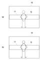
- FIG. 2 shows a diagram in which the monitoring area 11 is set in the first step.
- the monitoring area 11 is set so that the body part of the intruder 12 to be detected is included in the range of the monitoring area 11.
- the set monitoring area 11 is stored in the monitoring area storage means 2.
- the monitoring area 11 can be freely set as long as it is a part of the imaging area 10.
- the monitoring area 11 can be set while confirming the video using the monitor 8 for displaying the video of the camera 7 and a mouse (not shown).
- the method for setting the monitoring area 11 is not limited to that using the monitor 8 and the mouse, and any method may be used as long as the monitoring area 11 can be set.
- the non-monitoring area can be set and the monitoring area 11 can be specified.
- the video analysis means 3 performs the second step of making a determination under the following second condition.
- a portion drawn by a solid line included in the range of the monitoring area 11 in the entire image of the intruder 12 is a detection target portion. Further, portions not included in the range of the monitoring region 11 are indicated by dotted lines, and are excluded from detection targets in the first step.
- the video analysis means 3 determines that the condition of the first step is met. Then, the process proceeds to the second step.
- the intruder 12 includes the entire area including the part other than the monitoring area 11 as a target for determination of the conditions of the second step. The whole image of the person 12 is shown by a solid line.
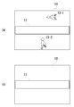
- FIG. 3A shows a case where the bird 13 is not included in the monitoring area 11.
- the bird 13 flies in the sky (13-1) or near the ground (13-2)
- a part of the bird 13 is not included in the range of the monitoring area 11.
- the birds 13-1 and 13-2 are not included in the range of the monitoring area 11, they are indicated by dotted lines here.
- the bird 13 does not meet the condition of the first step, and the video analysis means 3 excludes the bird 13 from the detection target.
- the bird 13 is not determined in the second step and is treated as not existing in the imaging area 10. That is, the bird 13 that does not cover the monitoring area 11 can be excluded from the detection target, and the detection efficiency can be increased.
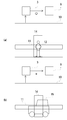
- FIG. 4 shows an image in which the effective area 14 is set.
- description will be made assuming that the intruder 12 in the video has already been determined to be included in the range of the monitoring area 11 in the first step and has shifted to the second step.
- the setting of the effective area 14 can be performed while confirming the video with the monitor 8 and the mouse.
- a specific range where the detection target is expected to fall within the range is set as the effective area 14 and stored in the effective area information storage unit 4.
- the effective area 14 is set at a size that allows the intruder 12 to fall within the range and a position where the intruder 12 is expected to pass.
- the entire image of the object that has entered the imaging area is subject to condition determination. That is, in the determination in the monitoring area 11 which is the condition of the first step, it is only necessary that a part of the object exists in the monitoring area, and the other part is located in an area other than the monitoring area 11. Will also meet the conditions. Then, in the second step, it is determined whether the condition of the second step is met in the entire image of the imaging region and the object including the part located outside the monitoring region 11.
- FIG. 4A shows a case where the object falls within the effective area 14.
- the intruder 12 falls within the set effective area 14, and the video analysis means 3 determines that the intruder 12 meets the second standard and identifies it as a detection target.
- the determination result of the video analysis means 3 is transmitted to the notification means 9 through a communication line or the like, and the presence of the detection target can be notified to the monitor by an alarm using sound or a lamp.
- FIG. 4B shows a case where the object does not fit within the effective area 14.
- the automobile 15 is larger than the intruder 12 and does not fall within the set effective area 14 but protrudes from the range.
- the determination of the condition of the second step it is determined that the automobile 15 does not meet the condition, and is excluded from the detection target.
- the video analysis means 3 determines that the second step condition criteria is not met, the notification means 9 does not operate.
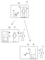
- FIG. 5 shows an image in which the upper and lower limits of the intruder 12 are set as the object reference information.
- the description will be made assuming that the intruder 12 and the bird 13 in the video have already been determined to be included in the range of the monitoring area 11 in the first step, and have shifted to the second step.
- the object reference information can be set while confirming the image with the monitor 8 and the mouse, similarly to the setting of the monitoring area 11.
- a range between upper and lower limits according to the size and shape of the detection target is set as object reference information and stored in the object reference information storage means 5.
- the upper limit for example, a large rectangle 16
- the lower limit for example, a small rectangle 17
- the rectangle is an example of a shape for setting the upper and lower limit ranges, and the shape for determining the range is not limited to the rectangle.
- FIG. 5B shows a case where the intruder 12 exists in the imaging area and meets the conditions of the second step.
- the intruder 12 is an object that is smaller than the large rectangle 16 and larger than the small rectangle 17, and is included within the set upper and lower limits, so the video analysis means 3 identifies the intruder 12 as a detection target.
- the determination result of the video analysis means 3 is transmitted to the notification means 9 through a communication line or the like, and the presence of the detection target can be notified to the monitor by an alarm using sound or a lamp.
- FIG. 5C shows a case where only the bird 13 exists in the video and does not meet the second step condition.
- the bird 13 is an object smaller than the small rectangle 17 and is less than the set lower limit.
- the determination of the condition of the second step it is determined that the bird 13 does not match the condition, and is excluded from the detection target.
- the bird 13 since the bird 13 does not fall within the upper and lower limits, it is indicated by a dotted line here. In this condition, an object larger than the large rectangle 16 does not meet the criteria of the second step condition and is excluded from the detection target. If the video analysis means 3 determines that the second step condition criteria is not met, the notification means 9 does not operate.
- the conditions included in the upper and lower limits are used as the condition criteria for the second step, but the setting of the conditions is not limited to this. It is also possible to set the reference only by the upper limit or the lower limit of the object shape. Conditions can be changed according to the size and shape of the object to be detected.
- the size and shape of the object vary depending on the position where the camera 7 is installed and the width and depth of the shooting range. Specifically, when an area with a large depth is imaged, the size and shape of the object located on the near side of the imaging area and the object located on the far side are significantly different. In such a case, a combination of a plurality of upper and lower limits can be set, and it can be determined that the condition of the second step is met when any of the conditions is met.
- the monitoring system 1 when the effective area and the object reference information are used as the conditions of the second step has been described. Subsequently, the criteria that can be set as the condition of the second step will be described as other embodiments.
- a monitoring system 1 including an imaging area position time information storage unit is given.
- the imaging area position time information indicates the time when the object is located in the imaging area 10, and the video analysis means 3 determines whether or not the second step condition is met with the imaging area position time information.
- the second step condition is set. For example, when it is desired to detect a pest that stays in the field for a certain period of time and damages the crop, the pest can be detected by setting a time slightly shorter than the time for staying in the field.
- the setting is made so as to meet the condition of the second step if the predetermined time is not exceeded. For example, if you want to detect a car entering and exiting a parking lot where a parking ticket machine is installed, by setting a time shorter than the average time until the car stops near the machine and leaves, Cars entering and exiting can be detected.
- the acceleration information refers to the acceleration when the object moves in the imaging region, and the video analysis means 3 determines whether or not the second step condition is met with the acceleration information.
- an acceleration slightly smaller than the acceleration when a human starts to move quickly is set as a reference. An object that moves faster than this acceleration can be detected as a burglar or a suspicious person.
- the setting is made so as to meet the condition of the second step if the predetermined acceleration is not exceeded.
- the predetermined acceleration For example, when it is desired to observe the behavior of a slow-moving animal, an acceleration that is slightly larger than the movement of the target animal is set as a reference. An animal that moves slower than the acceleration can be detected as an observation target.
- a monitoring system 1 provided with color tone information storage means is given.
- the color tone information refers to the color tone of the object, and the video analysis means 3 determines whether or not the second step condition is met with the color tone information.
- the setting is performed so as to meet the condition of the second step when the specific color tone is detected. For example, when it is desired to detect only a red car, it is possible to detect only a red car by setting a red color tone as a reference.
- Luminance information refers to the brightness of an object
- the video analysis means 3 determines whether or not the condition of the second step is met with the luminance information.
- the imaging area When it is desired to detect a bright object in the imaging area, it is set as a condition that satisfies the condition of the second step when a predetermined luminance is exceeded. For example, when it is desired to detect a car passing on a road where night traffic is prohibited, the brightness is set slightly lower than the brightness of the car light. When the vehicle passes with a light, it can be detected as an object having brightness exceeding the reference luminance.
- the setting is made so as to meet the condition of the second step when the predetermined luminance is not exceeded.
- the luminance is set to be slightly weaker than the brightness of the bicycle light. When an unlit bicycle passes, it can be detected as an object that does not exceed the standard brightness.
- a monitoring system 1 having an area occupancy rate information storage unit is given.
- the area occupancy information refers to the area occupancy occupied by the object in the imaging region, and the video analysis means 3 determines whether the condition of the second step is met with the area occupancy information.
- a setting is made so as to meet the condition of the second step when the predetermined area ratio is not exceeded.
- a value that is slightly larger than the area occupancy rate of objects that pass far Set. An object passing through a distance occupies a small area in the imaging region and can be detected because it does not exceed the reference area ratio.
- a monitoring system 1 having a volume information storage means is given.
- the sound volume information refers to the sound volume information emitted by the object, and the video analysis means 3 determines whether or not the second step condition is met with the sound volume information.
- the condition of volume information can be used to detect an abnormality in a production line of a precision machine that is difficult for humans to enter.
- the sound does not increase during normal operation, but when the drive sound increases during an abnormality, the sound volume is set to be slightly lower than the drive sound during the abnormality.
- the observer can detect the abnormality without approaching the production line.
- a setting is made so as to meet the condition of the second step when the predetermined volume is not exceeded. For example, when it is desired to detect the start of a quiet electric vehicle, a sound that is slightly louder than the start sound is used as a reference. When the electric vehicle starts, it can be detected because it is an object that emits a sound smaller than the reference sound.
- the temperature information refers to information on the temperature of the object, and the video analysis means 3 determines whether or not the condition of the second step is met with the temperature information.
- a high-temperature object When it is desired to detect a high-temperature object, it is set so as to meet the conditions of the second step when a predetermined temperature is exceeded. For example, when it is desired to detect arson in a garbage dump, a temperature slightly lower than the temperature emitted by a heat source such as a lighter is set as a reference. The presence of a light source such as a lighter can be detected because it exceeds the reference temperature.
- the setting is made so as to meet the condition of the second step. For example, when it is desired to detect an abnormal temperature drop in a greenhouse that grows a crop by controlling the temperature, the temperature is set based on the lower limit temperature of a temperature zone suitable for growing the crop. It can be detected when the temperature falls below the standard temperature due to climatic conditions or temperature control in the house.
- Humidity information refers to information on the humidity of the object, and the video analysis means 3 determines whether or not the condition of the second step is met with the humidity information.
- a predetermined humidity is set as a reference in a museum exhibition room where it is desired to keep the humidity below a certain level. It can be detected when the glass for exhibition has condensed due to the setting of air conditioning or the climate, and the humidity exceeds a predetermined standard.
- Odor information refers to odor information of an object
- the video analysis means 3 determines whether or not the second step condition is met with the odor information.
- the setting is made so as to meet the condition of the second step.
- the odor intensity when the chemical substance volatilizes is set as a reference. It can be detected when a chemical substance leaks for some reason and exceeds the standard odor intensity.
- the monitoring system to which the present invention is applied sets the first reference whether or not a part of the object in the video is included in the range of the monitoring area and the predetermined second reference, By determining whether or not these match, it is possible to efficiently detect the detection target.
- the condition of the second step can be set using various parameters of the object such as time, acceleration, color tone, and luminance located in the imaging region. It is possible to detect an object by providing a reference under conditions that match the characteristics of the detection target without depending on only the shape of the object.
- the object that matches the condition of the first step by the monitoring area has the whole image of the object that has entered the imaging area, and performs the determination of the second step.
- the entire image of the detection target can be clarified as compared with a monitoring system that simply limits the range to be monitored.
- the accuracy of detection can be improved by making a determination based on the conditions of the second step.
- the monitoring system to which the present invention is applied can efficiently detect the target to be monitored from the video.
Landscapes
- Engineering & Computer Science (AREA)
- Physics & Mathematics (AREA)
- General Physics & Mathematics (AREA)
- Theoretical Computer Science (AREA)
- Multimedia (AREA)
- Computer Vision & Pattern Recognition (AREA)
- Human Computer Interaction (AREA)
- Signal Processing (AREA)
- Alarm Systems (AREA)
- Closed-Circuit Television Systems (AREA)
- Image Analysis (AREA)
- Burglar Alarm Systems (AREA)
- Radar Systems Or Details Thereof (AREA)
Abstract
Priority Applications (10)
| Application Number | Priority Date | Filing Date | Title |
|---|---|---|---|
| KR1020157021294A KR101767497B1 (ko) | 2013-01-29 | 2013-01-29 | 감시 시스템 |
| US14/762,830 US9905009B2 (en) | 2013-01-29 | 2013-01-29 | Monitor system |
| PCT/JP2013/051822 WO2014118872A1 (fr) | 2013-01-29 | 2013-01-29 | Système de surveillance |
| MYPI2015702410A MY168266A (en) | 2013-01-29 | 2013-01-29 | Surveillance system |
| CN201380071683.3A CN104969542B (zh) | 2013-01-29 | 2013-01-29 | 监视系统 |
| JP2014559371A JP5870470B2 (ja) | 2013-01-29 | 2013-01-29 | 監視システム |
| EP13873274.8A EP2953349B1 (fr) | 2013-01-29 | 2013-01-29 | Système de surveillance |
| CA2897910A CA2897910C (fr) | 2013-01-29 | 2013-01-29 | Systeme de surveillance |
| HK16100199.1A HK1213116A1 (zh) | 2013-01-29 | 2016-01-08 | 監視系統 |
| US15/867,194 US10134140B2 (en) | 2013-01-29 | 2018-01-10 | Monitor system |
Applications Claiming Priority (1)
| Application Number | Priority Date | Filing Date | Title |
|---|---|---|---|
| PCT/JP2013/051822 WO2014118872A1 (fr) | 2013-01-29 | 2013-01-29 | Système de surveillance |
Related Child Applications (2)
| Application Number | Title | Priority Date | Filing Date |
|---|---|---|---|
| US14/762,830 A-371-Of-International US9905009B2 (en) | 2013-01-29 | 2013-01-29 | Monitor system |
| US15/867,194 Continuation US10134140B2 (en) | 2013-01-29 | 2018-01-10 | Monitor system |
Publications (1)
| Publication Number | Publication Date |
|---|---|
| WO2014118872A1 true WO2014118872A1 (fr) | 2014-08-07 |
Family
ID=51261622
Family Applications (1)
| Application Number | Title | Priority Date | Filing Date |
|---|---|---|---|
| PCT/JP2013/051822 WO2014118872A1 (fr) | 2013-01-29 | 2013-01-29 | Système de surveillance |
Country Status (9)
| Country | Link |
|---|---|
| US (2) | US9905009B2 (fr) |
| EP (1) | EP2953349B1 (fr) |
| JP (1) | JP5870470B2 (fr) |
| KR (1) | KR101767497B1 (fr) |
| CN (1) | CN104969542B (fr) |
| CA (1) | CA2897910C (fr) |
| HK (1) | HK1213116A1 (fr) |
| MY (1) | MY168266A (fr) |
| WO (1) | WO2014118872A1 (fr) |
Cited By (4)
| Publication number | Priority date | Publication date | Assignee | Title |
|---|---|---|---|---|
| CN105120191A (zh) * | 2015-07-31 | 2015-12-02 | 小米科技有限责任公司 | 视频录制方法和装置 |
| JP2019220024A (ja) * | 2018-06-21 | 2019-12-26 | キヤノン株式会社 | 画像処理装置およびその制御方法 |
| JP2019220895A (ja) * | 2018-06-21 | 2019-12-26 | 日本電気株式会社 | 画像処理装置、画像処理方法、プログラム、および画像処理システム |
| JP2021054597A (ja) * | 2019-09-30 | 2021-04-08 | 新明和工業株式会社 | 塵芥収集車及びメンテナンス装置 |
Families Citing this family (3)
| Publication number | Priority date | Publication date | Assignee | Title |
|---|---|---|---|---|
| US10322801B1 (en) | 2015-06-12 | 2019-06-18 | Amazon Technologies, Inc. | Unmanned aerial vehicle based surveillance as a service |
| US10313638B1 (en) | 2015-06-12 | 2019-06-04 | Amazon Technologies, Inc. | Image creation using geo-fence data |
| JP6965803B2 (ja) * | 2018-03-20 | 2021-11-10 | 株式会社Jvcケンウッド | 認識装置、認識方法及び認識プログラム |
Citations (8)
| Publication number | Priority date | Publication date | Assignee | Title |
|---|---|---|---|---|
| JP2004289581A (ja) * | 2003-03-24 | 2004-10-14 | Minolta Co Ltd | 監視システム |
| JP2005129003A (ja) * | 2003-06-09 | 2005-05-19 | Hitachi Kokusai Electric Inc | 変化検出装置 |
| WO2005107240A1 (fr) * | 2004-04-28 | 2005-11-10 | Chuo Electronics Co., Ltd. | Procede et appareil d'imagerie automatique |
| JP2007274655A (ja) * | 2006-03-31 | 2007-10-18 | Saxa Inc | 監視映像処理装置及び方法 |
| JP2008241707A (ja) * | 2008-03-17 | 2008-10-09 | Hitachi Kokusai Electric Inc | 自動監視システム |
| JP2008250898A (ja) | 2007-03-30 | 2008-10-16 | Victor Co Of Japan Ltd | 監視制御装置 |
| WO2008139529A1 (fr) * | 2007-04-27 | 2008-11-20 | Honda Motor Co., Ltd. | Système de surveillance de périphérie de véhicule, programme de surveillance de périphérie de véhicule et procédé de surveillance de périphérie de véhicule |
| JP2012243161A (ja) * | 2011-05-20 | 2012-12-10 | Canon Inc | 画像処理装置、画像処理方法 |
Family Cites Families (21)
| Publication number | Priority date | Publication date | Assignee | Title |
|---|---|---|---|---|
| GB2183878B (en) * | 1985-10-11 | 1989-09-20 | Matsushita Electric Works Ltd | Abnormality supervising system |
| US6028626A (en) * | 1995-01-03 | 2000-02-22 | Arc Incorporated | Abnormality detection and surveillance system |
| JPH09186927A (ja) * | 1995-12-28 | 1997-07-15 | Sony Corp | 追尾装置および追尾方法 |
| JPH1066054A (ja) * | 1996-08-20 | 1998-03-06 | Fujitsu General Ltd | 映像監視装置 |
| US6445409B1 (en) * | 1997-05-14 | 2002-09-03 | Hitachi Denshi Kabushiki Kaisha | Method of distinguishing a moving object and apparatus of tracking and monitoring a moving object |
| WO1998056182A1 (fr) | 1997-06-04 | 1998-12-10 | Ascom Systec Ag | Procede pour surveiller une zone de surveillance predefinie |
| US6064429A (en) * | 1997-08-18 | 2000-05-16 | Mcdonnell Douglas Corporation | Foreign object video detection and alert system and method |
| WO2001069932A1 (fr) | 2000-03-10 | 2001-09-20 | Sensormatic Electronics Corporation | Procede et appareil pour la poursuite et la detection d'un objet |
| JP3698420B2 (ja) | 2001-06-12 | 2005-09-21 | シャープ株式会社 | 画像監視装置及び画像監視方法及び画像監視処理プログラム |
| DE602004015173D1 (de) | 2003-01-21 | 2008-09-04 | Canon Kk | Bildaufnahmegerät und Bildaufnahmesystem |
| KR100696728B1 (ko) | 2003-06-09 | 2007-03-20 | 가부시키가이샤 히다치 고쿠사이 덴키 | 감시정보송신장치 및 감시정보송신방법 |
| JP4508038B2 (ja) * | 2005-03-23 | 2010-07-21 | 日本ビクター株式会社 | 画像処理装置 |
| US20070069920A1 (en) * | 2005-09-23 | 2007-03-29 | A-Hamid Hakki | System and method for traffic related information display, traffic surveillance and control |
| US7908237B2 (en) * | 2007-06-29 | 2011-03-15 | International Business Machines Corporation | Method and apparatus for identifying unexpected behavior of a customer in a retail environment using detected location data, temperature, humidity, lighting conditions, music, and odors |
| WO2010024281A1 (fr) | 2008-08-28 | 2010-03-04 | 有限会社ラムロック映像技術研究所 | Système de contrôle |
| US9030555B2 (en) | 2009-11-25 | 2015-05-12 | Lg Electronics Inc. | Surveillance system |
| US8438175B2 (en) * | 2010-03-17 | 2013-05-07 | Lighthaus Logic Inc. | Systems, methods and articles for video analysis reporting |
| US9615064B2 (en) * | 2010-12-30 | 2017-04-04 | Pelco, Inc. | Tracking moving objects using a camera network |
| WO2013058830A1 (fr) * | 2011-10-19 | 2013-04-25 | Balu Subramanya | Capteur de vitesse et de distance directionnel |
| WO2014063020A1 (fr) | 2012-10-18 | 2014-04-24 | Chornenky T Eric | Appareil et procédé de détermination d'informations spatiales concernant un environnement |
| US9638800B1 (en) * | 2016-11-22 | 2017-05-02 | 4Sense, Inc. | Passive tracking system |
-
2013
- 2013-01-29 CN CN201380071683.3A patent/CN104969542B/zh active Active
- 2013-01-29 US US14/762,830 patent/US9905009B2/en active Active
- 2013-01-29 KR KR1020157021294A patent/KR101767497B1/ko active IP Right Grant
- 2013-01-29 MY MYPI2015702410A patent/MY168266A/en unknown
- 2013-01-29 CA CA2897910A patent/CA2897910C/fr active Active
- 2013-01-29 EP EP13873274.8A patent/EP2953349B1/fr active Active
- 2013-01-29 JP JP2014559371A patent/JP5870470B2/ja active Active
- 2013-01-29 WO PCT/JP2013/051822 patent/WO2014118872A1/fr active Application Filing
-
2016
- 2016-01-08 HK HK16100199.1A patent/HK1213116A1/zh unknown
-
2018
- 2018-01-10 US US15/867,194 patent/US10134140B2/en active Active
Patent Citations (8)
| Publication number | Priority date | Publication date | Assignee | Title |
|---|---|---|---|---|
| JP2004289581A (ja) * | 2003-03-24 | 2004-10-14 | Minolta Co Ltd | 監視システム |
| JP2005129003A (ja) * | 2003-06-09 | 2005-05-19 | Hitachi Kokusai Electric Inc | 変化検出装置 |
| WO2005107240A1 (fr) * | 2004-04-28 | 2005-11-10 | Chuo Electronics Co., Ltd. | Procede et appareil d'imagerie automatique |
| JP2007274655A (ja) * | 2006-03-31 | 2007-10-18 | Saxa Inc | 監視映像処理装置及び方法 |
| JP2008250898A (ja) | 2007-03-30 | 2008-10-16 | Victor Co Of Japan Ltd | 監視制御装置 |
| WO2008139529A1 (fr) * | 2007-04-27 | 2008-11-20 | Honda Motor Co., Ltd. | Système de surveillance de périphérie de véhicule, programme de surveillance de périphérie de véhicule et procédé de surveillance de périphérie de véhicule |
| JP2008241707A (ja) * | 2008-03-17 | 2008-10-09 | Hitachi Kokusai Electric Inc | 自動監視システム |
| JP2012243161A (ja) * | 2011-05-20 | 2012-12-10 | Canon Inc | 画像処理装置、画像処理方法 |
Non-Patent Citations (1)
| Title |
|---|
| See also references of EP2953349A4 |
Cited By (9)
| Publication number | Priority date | Publication date | Assignee | Title |
|---|---|---|---|---|
| CN105120191A (zh) * | 2015-07-31 | 2015-12-02 | 小米科技有限责任公司 | 视频录制方法和装置 |
| KR101743194B1 (ko) * | 2015-07-31 | 2017-06-02 | 시아오미 아이엔씨. | 동영상 촬영 방법, 그 장치, 프로그램 및 기록매체 |
| JP2019220024A (ja) * | 2018-06-21 | 2019-12-26 | キヤノン株式会社 | 画像処理装置およびその制御方法 |
| JP2019220895A (ja) * | 2018-06-21 | 2019-12-26 | 日本電気株式会社 | 画像処理装置、画像処理方法、プログラム、および画像処理システム |
| CN113507595A (zh) * | 2018-06-21 | 2021-10-15 | 佳能株式会社 | 图像处理装置、图像处理方法和介质 |
| JP7115058B2 (ja) | 2018-06-21 | 2022-08-09 | 日本電気株式会社 | 画像処理装置、画像処理方法、プログラム、および画像処理システム |
| JP7216487B2 (ja) | 2018-06-21 | 2023-02-01 | キヤノン株式会社 | 画像処理装置およびその制御方法 |
| JP2021054597A (ja) * | 2019-09-30 | 2021-04-08 | 新明和工業株式会社 | 塵芥収集車及びメンテナンス装置 |
| JP7311377B2 (ja) | 2019-09-30 | 2023-07-19 | 新明和工業株式会社 | 塵芥収集車のメンテナンス装置 |
Also Published As
| Publication number | Publication date |
|---|---|
| US20150324990A1 (en) | 2015-11-12 |
| EP2953349B1 (fr) | 2023-07-19 |
| JP5870470B2 (ja) | 2016-03-01 |
| KR20150104182A (ko) | 2015-09-14 |
| CA2897910C (fr) | 2018-07-17 |
| JPWO2014118872A1 (ja) | 2017-01-26 |
| US10134140B2 (en) | 2018-11-20 |
| HK1213116A1 (zh) | 2016-06-24 |
| CA2897910A1 (fr) | 2014-08-07 |
| EP2953349A4 (fr) | 2017-03-08 |
| MY168266A (en) | 2018-10-16 |
| KR101767497B1 (ko) | 2017-08-11 |
| EP2953349A1 (fr) | 2015-12-09 |
| CN104969542B (zh) | 2019-05-31 |
| CN104969542A (zh) | 2015-10-07 |
| US20180130211A1 (en) | 2018-05-10 |
| US9905009B2 (en) | 2018-02-27 |
Similar Documents
| Publication | Publication Date | Title |
|---|---|---|
| JP5870470B2 (ja) | 監視システム | |
| CN106375712A (zh) | 使用微移动无人机及ip摄像机的家庭、办公室安全监视系统 | |
| WO2016133735A1 (fr) | Appareil de détection d'incendie utilisant une caméra | |
| KR101575011B1 (ko) | 영상을 이용한 적외선감지기와 그 동작방법 및 이를 이용한 보안시설물 통합관리시스템 | |
| JP7249260B2 (ja) | 緊急事態通知システム | |
| US20160217668A1 (en) | Alarm Routing In Integrated Security System Based On Security Guards Real-Time Location Information In The Premises For Faster Alarm Response | |
| KR101936837B1 (ko) | 맵기반 지능형 영상통합 감시시스템 및 이를 이용한 감시 방법 | |
| CN107302649A (zh) | 用于建筑物的外部区域的摄像机装置 | |
| US20120147182A1 (en) | Method to monitor an area | |
| US11592404B2 (en) | Close object detection for monitoring cameras | |
| US9507050B2 (en) | Entity detection system and method for monitoring an area | |
| KR102513372B1 (ko) | 음향과 영상을 연계한 하이브리드형 객체 연속 추적시스템 및 제어방법 | |
| JP5475593B2 (ja) | 複合型センサ | |
| JP4220322B2 (ja) | 侵入者監視方法及び装置 | |
| EP3293715B1 (fr) | Équipement autonome de surveillance de zone par capteur infrarouge passif multizone | |
| KR102633616B1 (ko) | 군 중요 시설 경계 작전 시스템 | |
| JP2013005336A (ja) | 監視装置、警備システム及び監視装置用プログラム | |
| JP2001266114A (ja) | 画像センサ | |
| WO2023180275A1 (fr) | Système de sécurité et procédé d'estimation d'intrusion par un objet dans un espace | |
| EP4272196A1 (fr) | Dispositif de surveillance d'un environnement | |
| TW202109467A (zh) | 智慧型燈具以及工地管理系統 | |
| JP2020181481A (ja) | セキュリティシステム |
Legal Events
| Date | Code | Title | Description |
|---|---|---|---|
| 121 | Ep: the epo has been informed by wipo that ep was designated in this application |
Ref document number: 13873274 Country of ref document: EP Kind code of ref document: A1 |
|
| DPE1 | Request for preliminary examination filed after expiration of 19th month from priority date (pct application filed from 20040101) | ||
| ENP | Entry into the national phase |
Ref document number: 2897910 Country of ref document: CA |
|
| WWE | Wipo information: entry into national phase |
Ref document number: 14762830 Country of ref document: US Ref document number: P945/2015 Country of ref document: AE |
|
| ENP | Entry into the national phase |
Ref document number: 2014559371 Country of ref document: JP Kind code of ref document: A |
|
| WWE | Wipo information: entry into national phase |
Ref document number: 2013873274 Country of ref document: EP |
|
| NENP | Non-entry into the national phase |
Ref country code: DE |
|
| ENP | Entry into the national phase |
Ref document number: 20157021294 Country of ref document: KR Kind code of ref document: A |
|
| WWE | Wipo information: entry into national phase |
Ref document number: IDP00201505221 Country of ref document: ID |