WO2014115808A1 - 電子機器、および電子機器操作制御プログラム - Google Patents
電子機器、および電子機器操作制御プログラム Download PDFInfo
- Publication number
- WO2014115808A1 WO2014115808A1 PCT/JP2014/051387 JP2014051387W WO2014115808A1 WO 2014115808 A1 WO2014115808 A1 WO 2014115808A1 JP 2014051387 W JP2014051387 W JP 2014051387W WO 2014115808 A1 WO2014115808 A1 WO 2014115808A1
- Authority
- WO
- WIPO (PCT)
- Prior art keywords
- pressing
- time
- pressure
- electronic device
- touch panel
- Prior art date
- Legal status (The legal status is an assumption and is not a legal conclusion. Google has not performed a legal analysis and makes no representation as to the accuracy of the status listed.)
- Ceased
Links
Images




Classifications
-
- G—PHYSICS
- G06—COMPUTING OR CALCULATING; COUNTING
- G06F—ELECTRIC DIGITAL DATA PROCESSING
- G06F3/00—Input arrangements for transferring data to be processed into a form capable of being handled by the computer; Output arrangements for transferring data from processing unit to output unit, e.g. interface arrangements
- G06F3/01—Input arrangements or combined input and output arrangements for interaction between user and computer
- G06F3/03—Arrangements for converting the position or the displacement of a member into a coded form
- G06F3/041—Digitisers, e.g. for touch screens or touch pads, characterised by the transducing means
-
- G—PHYSICS
- G06—COMPUTING OR CALCULATING; COUNTING
- G06F—ELECTRIC DIGITAL DATA PROCESSING
- G06F3/00—Input arrangements for transferring data to be processed into a form capable of being handled by the computer; Output arrangements for transferring data from processing unit to output unit, e.g. interface arrangements
- G06F3/01—Input arrangements or combined input and output arrangements for interaction between user and computer
- G06F3/03—Arrangements for converting the position or the displacement of a member into a coded form
- G06F3/033—Pointing devices displaced or positioned by the user, e.g. mice, trackballs, pens or joysticks; Accessories therefor
- G06F3/039—Accessories therefor, e.g. mouse pads
- G06F3/0393—Accessories for touch pads or touch screens, e.g. mechanical guides added to touch screens for drawing straight lines, hard keys overlaying touch screens or touch pads
-
- G—PHYSICS
- G06—COMPUTING OR CALCULATING; COUNTING
- G06F—ELECTRIC DIGITAL DATA PROCESSING
- G06F3/00—Input arrangements for transferring data to be processed into a form capable of being handled by the computer; Output arrangements for transferring data from processing unit to output unit, e.g. interface arrangements
- G06F3/01—Input arrangements or combined input and output arrangements for interaction between user and computer
- G06F3/03—Arrangements for converting the position or the displacement of a member into a coded form
- G06F3/041—Digitisers, e.g. for touch screens or touch pads, characterised by the transducing means
- G06F3/0416—Control or interface arrangements specially adapted for digitisers
-
- G—PHYSICS
- G06—COMPUTING OR CALCULATING; COUNTING
- G06F—ELECTRIC DIGITAL DATA PROCESSING
- G06F3/00—Input arrangements for transferring data to be processed into a form capable of being handled by the computer; Output arrangements for transferring data from processing unit to output unit, e.g. interface arrangements
- G06F3/01—Input arrangements or combined input and output arrangements for interaction between user and computer
- G06F3/048—Interaction techniques based on graphical user interfaces [GUI]
- G06F3/0487—Interaction techniques based on graphical user interfaces [GUI] using specific features provided by the input device, e.g. functions controlled by the rotation of a mouse with dual sensing arrangements, or of the nature of the input device, e.g. tap gestures based on pressure sensed by a digitiser
- G06F3/0488—Interaction techniques based on graphical user interfaces [GUI] using specific features provided by the input device, e.g. functions controlled by the rotation of a mouse with dual sensing arrangements, or of the nature of the input device, e.g. tap gestures based on pressure sensed by a digitiser using a touch-screen or digitiser, e.g. input of commands through traced gestures
Definitions
- the present invention relates to an electronic device and an electronic device operation control program.
- the present application claims priority based on Japanese Patent Application No. 2013-010911 filed in Japan on January 24, 2013, the contents of which are incorporated herein by reference.
- an electronic device particularly a portable electronic device having a touch sensor outside the housing
- the user's operation is detected by contact / proximity to the touch sensor such as the user's finger or a dedicated pen. Therefore, when such a portable electronic device is accommodated in a pocket or bag, a touch sensor may malfunction due to touching an object, and an operation that is not intended by the user may be erroneously input. There is a risk that a deletion instruction or the like may be input by mistake.
- a key lock switch that is a mechanical slide switch is provided in a housing, and a user slides the key lock switch to The input is invalidated to prevent erroneous detection / malfunction of the touch sensor when the notification means is activated.
- This invention is made in view of said point, and makes it a subject to provide the electronic device which can improve a user's convenience, and an electronic device operation control program.
- a pressure sensor unit that detects a pressing force generated by being pressed from the outside, a touch panel that outputs a signal corresponding to a contact position with which the operating body comes into contact, and the operating body from the pressure sensor unit to the press sensor unit Whether or not to enable the signal output from the touch panel based on the acquired pressure transition time based on the acquired pressure transition time.
- the determination unit acquires a pressing duration time during which the pressing sensor unit continues to detect the pressing force equal to or greater than a threshold value of the pressing force from the pressing sensor unit, The electronic device determines whether or not to validate the signal output from the touch panel based on the acquired pressing transition time and the pressing duration.
- the determination unit is based on the pressing force detected by the pressing sensor unit, the pressing transition time, the pressing duration time, and information on pressing force. It is determined whether or not the signal output from the touch panel is valid, and the information on the pressing force is information on the threshold value of the pressing force, information on the threshold value of the pressing transition time, and information on the pressing duration time. It is an electronic device that is information about a threshold.
- the pressure sensor unit is an electronic device located on a side surface of the electronic device.
- an electronic device includes: a pressing sensor unit that detects a pressing force generated by being pressed from the outside; and a touch panel that outputs a signal corresponding to a contact position with which the operating body contacts. And an electronic device operation control program for executing a determination step of determining whether or not to validate the signal output from the touch panel based on the pressing force detected by the pressing sensor unit.
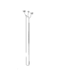
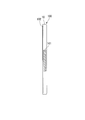
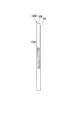
- FIG. 1A to 1C are external views of the electronic device 100 according to the first embodiment of the present invention.
- 1A is a left side view of the housing 10 of the electronic device 100
- FIG. 1B is a front view
- FIG. 1C is a right side view.
- the electronic device 100 is an electronic device with a PDA (personal digital assistant) function in addition to a telephone and mail function as an example, and is also called a multi-function mobile phone (smart phone).
- PDA personal digital assistant
- a touch panel 102 is provided on the front surface of the electronic device 100.
- the touch panel 102 is a member having a function for inputting information from the user and presenting information to the user.
- the input of information on the touch panel 102 is a part of the user's body (hereinafter sometimes referred to as an “operation body”), for example, operation information on the screen of the touch panel 102 with the index finger of either the left or right hand ( This is done by touching an icon, etc., or touching with a dedicated pen (stylus).
- Information on the touched screen position is output to the outside of the touch panel 102 as an information signal.
- a known method such as a pressure type, an electrostatic type, or a conductive type can be used.
- a pressure sensor unit 101 is provided on the right side when viewed from the front of the touch panel 102.
- the pressure sensor unit 101 detects a force (hereinafter referred to as “pressing force”) applied to the pressure sensor unit 101 by gripping the housing 10 with either the left or right hand, and determines the magnitude of the detected pressing force.
- the corresponding pressure detection value is output as an electrical signal.
- the pressure sensor unit 101 may include an external impact force that is received when the user places the electronic device 100 in a pocket of clothes or a bag that is carried with the user.
- the electrical signal is also output by the steady pressing force received by the case of packing together.
- the press sensor unit 101 provided on the side surface portion of the housing 10 detects the pressing force and outputs the detected press detection value to the outside of the press sensor unit 101 in the form of an electrical signal.
- FIG. 2 is a schematic block diagram illustrating an example of the configuration of the electronic device 100 according to the present embodiment.
- the electronic device 100 includes a press sensor unit 101, a touch panel 102, and a control unit 103.
- the control unit 103 includes a detection switching setting unit 1031, a contact detection unit 1032, an operation control unit 1033, a determination unit 1034, and a pressing information storage unit 1035.
- the electronic device 100 has other known functions of a multi-function mobile phone, but illustration and description thereof are omitted.
- the pressing sensor unit 101 detects a pressing force generated when the user grips the side surface of the housing 10 (FIGS. 1A to 1C) with either left or right hand.
- the pressure sensor unit 101 outputs a pressure detection value (electric signal) corresponding to the detected pressure level to the determination unit 1034.
- the press sensor unit 101 is a known piezoresistive sensor whose electric resistance value changes according to the magnitude of the pressing force.
- the touch panel 102 presents image information as a display device.
- the touch panel 102 generates an electrical signal representing position information of a position where a user's finger or the like has touched as an operation input device.
- the touch panel 102 outputs the generated electrical signal to the contact detection unit 1032.
- Various functions of the control unit 103 are realized by executing a program stored in a built-in storage device (not shown) by a built-in CPU (Central Processing Unit, not shown). .
- the control unit 103 for example, based on the pressure detection value input from the pressure sensor unit 101 and the information about the pressure detection value read from the pressure information storage unit 1035 included in the control unit 103, the pressure detection value is the pressure detection value. It is determined whether or not the threshold value is exceeded.
- the information regarding the pressure detection value is information regarding the threshold value of the pressure detection value, information regarding the threshold value of the transition time of the pressure detection value, and information regarding the threshold value of the duration of the pressure detection value.
- the control unit 103 validates or invalidates a signal output from the touch panel 102 based on the position coordinates of the position where the user's finger or the like contacts the touch panel 102 and the determination result of the press detection value. The operation of the control unit 103 will be described in detail later.
- the detection switching setting unit 1031 sets the input of the signal from the touch panel 102 to the contact detection unit 1032 to be invalid or valid in response to an instruction input from the determination unit 1034 via the contact detection unit 1032.
- Contact detection unit 1032 outputs a signal from touch panel 102 to operation control unit 1033.
- the contact detection unit 1032 causes the detection switching setting unit 1031 to set the input of the signal from the touch panel 102 to the contact detection unit 1032 to be invalid or valid according to the instruction input from the determination unit 1034.
- the operation control unit 1033 performs various operation processes corresponding to the signal input from the contact detection unit 1032.
- the determination unit 1034 reads information on the pressure detection value from the pressure information storage unit 1035. Specifically, the determination unit 1034 receives information about the threshold value of the pressure detection value from the pressure information storage unit 1035, and the pressure detection value reaches the threshold value of the pressure detection value from the time when the pressure sensor unit 101 starts detecting the pressure detection value. The information regarding the threshold value of the time until the detection and the information regarding the threshold value of the time when the pressure detection value continues to exceed the threshold value of the pressure detection value are read.
- the determination unit 1034 is a time until the time when the pressure detection value is detected based on the input from the pressure sensor unit 101 reaches the threshold value of the pressure detection value read from the pressure information storage unit 1035 (hereinafter referred to as a pressure transition time T1). Measured).
- the determination unit 1034 measures a continuation time (hereinafter, referred to as a pressure continuation time T2) in which the pressure detection value equal to or greater than the threshold is detected from the time when the pressure detection value reaches the threshold value of the pressure detection value.
- the determination unit 1034 includes a press determination unit 10341, a press transition time determination unit 10342, and a press duration determination unit 10343.
- the pressure determination unit 10341 determines whether or not the pressure detection value is equal to or greater than the threshold value P of the pressure detection value based on the information regarding the pressure force and the pressure detection value (first determination).
- the pressure transition time determination unit 10342 makes a determination regarding the pressure transition time T1 (second determination).
- the touch transition time determination unit 10342 determines that the signal input to the detection unit 1032 is valid. On the other hand, the pressure transition time determination unit 10342 determines to invalidate the input of the signal to the contact detection unit 1032 when the pressure detection value is less than the threshold value P of the pressure detection value or when the pressure detection value is not detected. To do.
- the press duration determination unit 10343 continues the detection of a press detection value that is equal to or greater than the threshold value P of the press detection value from the time when the press detection value reaches the threshold value P of the press detection value based on the second determination result. Is determined to be within the range of the threshold for the pressing duration time T2 (third determination). In a case where the duration for which the detected pressure value equal to or greater than the detected threshold value P is detected from the time when the detected pressure value reaches the detected threshold value P satisfies the threshold condition regarding the pressed duration T2, the pressed duration determination unit 10343 determines that the input of the signal to the contact detection unit 1032 is valid.
- the pressure continuation is continued when the threshold condition regarding the pressure duration T2 is not satisfied.
- the time determination unit 10343 determines that the input of the signal to the contact detection unit 1032 is invalidated.
- the press information storage unit 1035 includes information on the threshold value of the pressure detection value, information on the threshold value of the time during which the pressure detection value continues to exceed the threshold value of the pressure detection value, and the time when the pressure sensor unit 101 starts detecting the pressure detection value. Information regarding a threshold value of time until the pressure detection value reaches the threshold value of the pressure detection value is stored. In the present embodiment, the information related to the pressure detection value is stored in advance in the pressure information storage unit 1035. However, the user arbitrarily determines the information regarding the pressure detection value, and stores the determined information in the pressure information storage. You may memorize
- FIG. 3 is a diagram illustrating an example of a relationship among the press detection value, the press transition time T1, and the press duration time T2 according to the present embodiment.
- the horizontal axis indicates time
- the vertical axis indicates the detected pressure value.
- the time between time T1min and time T1max is the pressing transition time T1.
- the time from the time when the pressure detection value exceeds the threshold value P of the pressure detection value to the predetermined time tx is the lower limit time T2min of the threshold value of the pressing duration T2, and the pressure detection value exceeds the threshold value P of the pressure detection value.
- the time from the time to the predetermined time ty is the upper limit time T2max of the threshold value of the pressing duration T2.
- the press detection characteristic G1 will be described.
- the pressure detection characteristic G1 although the time is 0 and the pressure detection value is a non-contact value (for example, zero), the pressure detection value increases as time elapses, and the pressure detection value at time t1. Reaches the threshold value P of the pressure detection value, and continues to increase thereafter. Therefore, the press determination unit 10341 validates the first determination.
- the press determination unit 10341 validates the first determination.
- the condition, the lower limit T1min of the threshold value of the pressing transition time T1, and the upper limit T1max of the threshold value are set at the time T1.
- the pressing transition time T1 is, for example, 0.5 seconds.
- time A1 is required until the pressure detection value reaches the threshold value P of the pressure detection value.
- the time t1 which is the upper limit of the time A1
- the press transition time determination unit 10342 invalidates the second determination. In this case, it is considered that a part of the user's body or the like is temporarily in contact with the pressure sensor unit 101, and the determination unit 1034 determines to invalidate the signal input to the contact detection unit 1032.
- the press determination unit 10341 validates the first determination. Further, the time from time 0 to time t2 is within the range of the condition of the press transition time T1. That is, the press transition time determination unit 10342 performs the second determination regarding the press transition time T1, and as a result, determines that the input of the signal is valid.
- the pressure sensor unit 101 detects a pressure detection value equal to or greater than the pressure detection value threshold value P until time t6.
- the time A3 from time t2 to time t6 is the press duration time.
- the time A3 exceeds the lower limit time T2min of the threshold value of the pressing duration time T2 and satisfies the condition of the pressing duration time T1, but does not fall within the upper limit time T2max of the threshold value, and the upper limit of the pressing duration time T2.
- Time T2max is exceeded. Therefore, in this case, the electronic device 100 is regarded as being normally held by the user, and the pressing duration determination unit 10343 makes a third determination with respect to the time A3, and as a result, the touch panel 102 makes contact. It is determined that the signal input to the detection unit 1032 is invalidated.
- the press determination unit 10341 validates the first determination.
- the time from time 0 to time t3 is within the range of the press transition time T1. That is, the press transition time determination unit 10342 performs the second determination regarding the press transition time T1, and as a result, determines that the signal input from the touch panel 102 to the contact detection unit 1032 is valid.
- the pressure sensor unit 101 is equal to or greater than the pressure detection value threshold P at time A2 until time t4 when the pressure detection value reaches the pressure detection threshold value P or less. It continues to detect the pressure detection value.
- the time A2 does not satisfy the lower limit time T2min of the threshold value of the pressing duration time T2. That is, the pressing duration determination unit 10343 performs the third determination on the time A2, and as a result, determines that the input of the signal from the touch panel 102 to the contact detection unit 1032 is not valid.
- the press determination unit 10341 validates the first determination. Further, the time from time 0 to time t3 is within the range of the press transition time T1. The press transition time determination unit 10342 performs the second determination regarding the press transition time T1 and determines that the signal input from the touch panel 102 to the contact detection unit 1032 is valid.
- the pressure sensor unit 101 detects the pressure detection value at or after the threshold value P of the pressure detection value at time A4 from time t3 to time t5.
- the lower limit time of the pressing duration T2 is set as the time from time t3 to time tx when the pressure detection value in G4 reaches the pressure detection value threshold P, and the time from time t3 to time ty continues to be pressed.
- the time is the upper limit time of the threshold value of time T2
- the pressure detection characteristic G4 exceeds the lower limit time T1min of the threshold value of the press duration time T2, and is within the upper limit time T2max of the threshold value. Therefore, the pressing duration determination unit 10343 performs the third determination with respect to the time A4, and as a result, determines that the signal input from the touch panel 102 to the contact detection unit 1032 is valid.
- the determination unit 1034 performs the first determination, the second determination, and the third determination in the press detection characteristic G4, and enables input of the signal from the touch panel 102 to the contact detection unit 1032. If it is determined, the detection switching setting unit 1031 is enabled to input a signal from the touch panel 102 to the contact detection unit 1032. On the other hand, if the determination unit 1034 determines that the signal input is not validated in any of the first determination, the second determination, and the third determination, the signal from the touch panel 102 to the contact detection unit 1032 is displayed. The detection switching setting unit 1031 invalidates the input.
- the pressing transition time T1 is provided with the conditions of the lower limit T1min of the threshold and the upper limit T1max of the threshold, but only the condition of the lower limit T1min of the threshold may be used.
- the pressing duration T2 is provided with the conditions of the lower limit time T2min and the upper limit time T2max, but only the upper limit time T2max may be used.
- FIG. 4 is a flowchart illustrating an example of the operation of the determination unit 1034 according to the present embodiment.
- the determination unit 1034 determines whether or not the detection switching setting unit 1031 is invalidating the input of the signal from the touch panel 102 to the contact detection unit 1032.
- the signal input is set to be invalid (in the case of YES)
- the operation after step ST102 is performed.
- the setting is not invalid, that is, if the setting is valid (NO)
- the process returns to step ST101.
- step ST ⁇ b> 102 the press determination unit 10341 acquires a press detection value from the press sensor unit 101.
- step ST103 the pressure determination unit 10341 determines whether or not the pressure detection value detected by the pressure sensor unit 101 is greater than or equal to a non-contact value (for example, the pressure detection value is zero). If the detected pressure value is greater than or equal to the non-contact value (in the case of YES), the pressure determination unit 10341 determines that the application of the pressing force has started, and proceeds to step ST104. On the other hand, if the detected pressure value is less than the non-contact value (in the case of NO), the pressure determination unit 10341 determines that the application of the pressing force has not started, and returns to step ST102.
- a non-contact value for example, the pressure detection value is zero.
- step ST104 the press determination part 10341 determines whether a press detection value is more than the threshold value P of a press detection value.
- the process proceeds to step ST107.
- the pressure detection value is less than the threshold value P of the pressure detection value (in the case of NO)
- the press determination part 10341 determines whether a press detection value is a value at the time of non-contact.
- the pressure determination unit 10341 determines that the application of the pressing force has been released, and returns to step ST102.
- the pressure determination unit 10341 determines that the application of the pressing force is continued, proceeds to step ST106, and determines the pressure transition time.
- Unit 10342 starts measurement of pressing transition time T1, and returns to step ST104 after a certain time ⁇ t has elapsed.
- the pressing transition time determination unit 10342 determines whether or not the time from when the pressing detection value starts applying the pressing force until the pressing detection value threshold P is exceeded is within the pressing transition time T1. To do.
- step ST107 when the time during which the pressure detection value exceeds the threshold value P of the pressure detection value is within the range of the pressure transition time T1 (in the case of YES), the process proceeds to step ST109, and the pressure duration determination unit 10343 The measurement of the continuation time is started, and after a predetermined time ⁇ t has elapsed, the process proceeds to step ST110.
- step ST108 when the time during which the pressure detection value exceeds the threshold value P of the pressure detection value is not within the range of the pressure transition time T1 (in the case of NO) in step ST107, the process proceeds to step ST108, and the pressure transition time determination unit 10342 The measurement timer for the pressing transition time T1 is reset.
- step ST110 the press determination part 10341 determines whether a press detection value is less than the threshold value P of a press detection value.
- the process proceeds to step ST112.
- the process proceeds to step ST111.
- step ST111 when the time from step ST107 to step ST111 is equal to or longer than the upper limit time T2max of the pressing duration T2 (in the case of YES), the pressing duration determination unit 10343 has the pressing duration of the pressing duration T2. It determines with having exceeded the threshold value, proceeds to step ST108, resets the measurement timer, and then returns to step ST102. On the other hand, when the time from step ST107 to step ST111 is not equal to or greater than the upper limit time T2max of the pressing duration time T2 (in the case of NO), the process returns to step ST109.
- step ST112 when the time from step ST107 to step ST112 is within the range of the lower limit time T2min of the pressing duration T2 and the upper limit time T2max of the threshold (in the case of YES), the process proceeds to step ST113.
- the determination unit 1034 makes the detection switching setting unit 1031 validate the signal input from the touch panel to the contact detection unit 1032.
- the pressing duration determination unit 10343 determines that the pressing duration is the pressing duration. It determines with it being less than the threshold value of T2, progresses to step ST108, the press continuation time determination part 10343 resets a measurement timer, and returns to step ST102.
- the electronic device 100 includes a press sensor unit 101 that detects a pressing force generated by being pressed from the outside, a touch panel 102 that outputs a signal corresponding to a contact position with which the operating body contacts, and a press sensor.
- a pressing transition time from when the operating body is not in contact with the pressing sensor unit 101 to the pressing force threshold is acquired from the unit 101, and a signal output from the touch panel 102 is obtained based on the acquired pressing transition time.
- a determination unit 1034 that determines whether or not to validate. Thereby, the electronic device 100 can surely prevent malfunction and improve user convenience.
- FIG. 5A is a left side view of the electronic device 100A
- FIG. 5B is a front view
- FIG. 5C is a right side view.
- a touch panel 102 is provided on the front surface of the electronic device 100A.
- a pressure sensor unit 101 ⁇ / b> A is provided on the left side surface of the touch panel 102.
- description is abbreviate
- a touch panel 102 is provided on the front surface of the electronic device 100B.
- Press sensor units 101 and 101A are provided on both side surfaces of the touch panel 102.
- the user enables either the pressure sensor unit 101 or the pressure sensor unit 101A according to the dominant hand.
- description is abbreviate
- the user can select whether to enable the pressing sensor unit 101 or 101A, and the electronic device 100B can reliably prevent malfunctions due to the pressing force regardless of whether the user's dominant hand is left or right. It is possible to improve user convenience.
- the press sensor units 101 and 101A that detect the pressing force generated by being pressed from the outside, the touch panel 102 that outputs a signal corresponding to the contact position with which the operating body contacts, and the press sensor unit.
- 101, 101A acquires the pressing transition time from the pressing force when the operating body is not in contact with the pressing sensor unit 101, 101A to the pressing force threshold, and is output from the touch panel 102 based on the acquired pressing transition time.
- a determination unit 1034 for determining whether or not to enable the signal.
- the determination unit 1034 acquires the pressing duration time during which the pressing sensor units 101 and 101A continue to detect the pressing force equal to or greater than the pressing force threshold, and based on the acquired pressing transition time and the pressing duration time, the touch panel 102. It is determined whether or not the signal output from is valid.
- the determination unit 1034 determines whether or not to validate the signal output from the touch panel 102 based on the pressing force detected by the pressing sensor units 101 and 101A, the pressing transition time, the pressing duration time, and the information related to the pressing force.
- the information on the pressing force is information on the pressing force threshold, information on the pressing transition time threshold, and information on the pressing duration threshold.
- the determination unit 1034 validates the signal output from the touch panel 102 based on the pressing force detected by the pressing sensor units 101 and 101A, the pressing transition time T1, the pressing duration time T2, and the information regarding the pressing force. It is determined whether or not.
- the information related to the pressing force includes information related to the pressing force threshold value P, information related to the threshold value of the pressing transition time T1, and information related to the threshold value of the pressing duration time T2.
- the press sensor portions 101 and 101A are located on the side surfaces of the electronic devices 100, 100A and 100B.
- the determination unit 1034 invalidates the signal when detecting that the operating body does not contact the touch panel 102 for a predetermined time.
- the electronic device operation control method includes a detection step for detecting a pressing force generated by being pressed from the outside, an output step for outputting a signal corresponding to a contact position where the operating body contacts, and a pressing force detected in the detection step. And a determination step for determining whether or not to validate the signal output in the output step.
- the electronic device operation control program includes an electronic device 100 including press sensor units 101 and 101A that detect a pressing force generated by being pressed from the outside, and a touch panel 102 that outputs a signal corresponding to a contact position where the operating body contacts. , 100A and 100B are caused to execute a determination step of determining whether or not to validate a signal output from the touch panel 102 based on the pressing force detected by the pressing sensor units 101 and 101A.
- the portable terminal has been described as an example.
- the present invention is not limited to this, and may be a tablet terminal including a touch panel, a PDA, a personal computer, or the like as long as it is an electronic device including a touch panel.
- the program for realizing the control function may be recorded on a computer-readable recording medium, and the program recorded on the recording medium may be read by a computer system and executed.
- the “computer system” is a computer system built in the electronic devices 100, 100A, and 100B, and includes an OS and hardware such as peripheral devices.
- the “computer-readable recording medium” means a storage device such as a flexible disk, a magneto-optical disk, a portable medium such as a ROM and a CD-ROM, and a hard disk incorporated in a computer system.
- the “computer-readable recording medium” is a medium that dynamically holds a program for a short time, such as a communication line when transmitting a program via a network such as the Internet or a communication line such as a telephone line, In such a case, a volatile memory inside a computer system serving as a server or a client may be included and a program that holds a program for a certain period of time.
- the program may be a program for realizing a part of the above-described functions, and may be a program that can realize the above-described functions in combination with a program already recorded in a computer system.
- part or all of the electronic devices 100, 100A, and 100B in the above-described embodiments may be realized as an integrated circuit such as an LSI (Large Scale Integration).
- LSI Large Scale Integration
- Each functional block of the electronic devices 100, 100A, and 100B may be individually made into a processor, or a part or all of them may be integrated into a processor.
- the method of circuit integration is not limited to LSI, and may be realized by a dedicated circuit or a general-purpose processor. Further, in the case where an integrated circuit technology that replaces LSI appears due to progress in semiconductor technology, an integrated circuit based on the technology may be used.
- the present invention can be applied to an electronic device, an electronic device operation control program, and the like that need to reliably prevent malfunction of the electronic device and improve user convenience.
Landscapes
- Engineering & Computer Science (AREA)
- General Engineering & Computer Science (AREA)
- Theoretical Computer Science (AREA)
- Human Computer Interaction (AREA)
- Physics & Mathematics (AREA)
- General Physics & Mathematics (AREA)
- Position Input By Displaying (AREA)
- User Interface Of Digital Computer (AREA)
Abstract
押圧センサ部は、外部から押されることによって生じる押圧力を検出する。タッチパネルは、操作体が接触する接触位置に応じた信号を出力する。判定部は、押圧センサ部から操作体が押圧センサ部へ非接触時の押圧力から押圧力の閾値に達するまでの押圧遷移時間を取得し、取得した押圧遷移時間に基づいて、タッチパネルから出力される信号を有効とするか否かを判定する。
Description
本発明は、電子機器、および電子機器操作制御プログラムに関する。
本願は、2013年1月24日に、日本に出願された特願2013-010911号に基づき優先権を主張し、その内容をここに援用する。
本願は、2013年1月24日に、日本に出願された特願2013-010911号に基づき優先権を主張し、その内容をここに援用する。
電子機器、特にタッチセンサを筐体外部に備えた携帯電子機器においては、ユーザの指や専用ペンなどのタッチセンサに対する接触・近接によってユーザの操作を検出する。したがって、このような携帯電子機器をポケットや鞄に収容したときに、何らかの物体に触れてタッチセンサの誤動作が発生し、ユーザの意図しない操作が誤って入力される恐れがあり、また、情報の削除指示なども誤って入力されてしまう恐れがある。特許文献1に記載の技術は、タッチセンサを備えた携帯電子機器において、機械的なスライド式スイッチであるキーロックスイッチを筐体に設け、ユーザはこのキーロックスイッチをスライドしてタッチセンサ部の入力を無効にし、報知手段作動時におけるタッチセンサの誤検出/誤作動を防止するものである。
しかしながら、特許文献1に記載の技術では、電子機器の筐体のスライド式スイッチであるキーロックスイッチをスライドさせてロックし、タッチセンサ部の入力を無効にしても、ユーザの意図しない応力がキーロックスイッチのロックを解除する方向にスライドさせ、操作入力の無効を解除し、その結果、タッチセンサの望ましくない有効化を行ってしまうという欠点があった。このように、特許文献1の電子機器は、誤動作を防止できず、ユーザの利便性が十分でないという問題があった。
本発明は上記の点に鑑みてなされたものであり、ユーザの利便性を向上できる電子機器、および電子機器操作制御プログラムを提供することを課題とする。
(1)外部から押されることによって生じる押圧力を検出する押圧センサ部と、操作体が接触する接触位置に応じた信号を出力するタッチパネルと、前記押圧センサ部から前記操作体が前記押圧センサ部へ非接触時の前記押圧力から押圧力の閾値に達するまでの押圧遷移時間を取得し、取得した前記押圧遷移時間に基づいて、前記タッチパネルから出力される前記信号を有効とするか否かを判定する判定部と、を備える電子機器である。
(2)また、本発明の一態様は、前記判定部は、前記押圧センサ部から前記押圧センサ部が前記押圧力の閾値以上の前記押圧力を検出し続けている押圧継続時間を取得し、取得した前記押圧遷移時間と、前記押圧継続時間とに基づいて、前記タッチパネルから出力される前記信号を有効とするか否かを判定する電子機器である。
(3)また、本発明の一態様は、前記判定部は、前記押圧センサ部が検出した前記押圧力と、前記押圧遷移時間と、前記押圧継続時間と、押圧力に関する情報とに基づいて、前記タッチパネルから出力される前記信号を有効とするか否かを判定し、前記押圧力に関する情報は、前記押圧力の閾値に関する情報と、前記押圧遷移時間の閾値に関する情報と、前記押圧継続時間の閾値に関する情報とである電子機器である。
(4)また、本発明の一態様は、前記押圧センサ部は、前記電子機器の側面に位置する電子機器である。
(5)また、本発明の一態様は、外部から押されることによって生じる押圧力を検出する押圧センサ部と、操作体が接触する接触位置に応じた信号を出力するタッチパネルと、を備える電子機器に、前記押圧センサ部で検出された前記押圧力に基づいて、前記タッチパネルから出力される前記信号を有効とするか否かを判定する判定ステップを実行させるための電子機器操作制御プログラムである。
本発明の一態様によれば、ユーザの利便性を向上できる。
(第1の実施形態)
以下、図面を参照しながら本発明の第1の実施形態について詳述する。
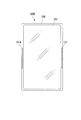
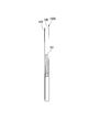
図1A~図1Cは、本発明の第1の実施形態に係る電子機器100の外観図である。図1Aは、電子機器100の筐体10の左側面図、図1Bは、正面図、図1Cは、右側面図である。
電子機器100は、一例として電話やメール機能の他にPDA(携帯情報端末)の機能が付いた電子機器であり、多機能携帯電話機(スマートフォン)とも称される。
以下、図面を参照しながら本発明の第1の実施形態について詳述する。
図1A~図1Cは、本発明の第1の実施形態に係る電子機器100の外観図である。図1Aは、電子機器100の筐体10の左側面図、図1Bは、正面図、図1Cは、右側面図である。
電子機器100は、一例として電話やメール機能の他にPDA(携帯情報端末)の機能が付いた電子機器であり、多機能携帯電話機(スマートフォン)とも称される。
電子機器100の前面には、タッチパネル102が備えられる。
タッチパネル102は、ユーザからの情報の入力およびユーザへの情報の提示を行うための機能を有する部材である。
タッチパネル102での情報の入力は、ユーザの体の一部(以下で、「操作体」と言うことがある。)、例えば、左右いずれかの手の人差し指でタッチパネル102の画面上の操作情報(アイコンなど)に触れたり、専用ペン(スタイラス)で触れたりすることで行われる。触れられた画面位置の情報は、タッチパネル102の外部へ情報信号として出力される。タッチパネル102の入力方法としては、加圧式、静電式、導電式など、公知の方法を用いることができる。
タッチパネル102は、ユーザからの情報の入力およびユーザへの情報の提示を行うための機能を有する部材である。
タッチパネル102での情報の入力は、ユーザの体の一部(以下で、「操作体」と言うことがある。)、例えば、左右いずれかの手の人差し指でタッチパネル102の画面上の操作情報(アイコンなど)に触れたり、専用ペン(スタイラス)で触れたりすることで行われる。触れられた画面位置の情報は、タッチパネル102の外部へ情報信号として出力される。タッチパネル102の入力方法としては、加圧式、静電式、導電式など、公知の方法を用いることができる。
タッチパネル102の正面から見て右側面には、押圧センサ部101が設けられる。
押圧センサ部101は、筐体10を左右いずれかの手で把持することにより押圧センサ部101に加わる力(以下、「押圧力」と称する。)を検出し、検出した押圧力の大きさに応じた押圧検出値を電気信号として出力する。その他に、押圧センサ部101は、電子機器100をユーザが洋服のポケットに入れたり、携行する鞄の中に入れたりすることで受ける外部衝撃力や、近接物(鞄の中にいろいろな物と一緒に詰め込んだりする場合の物)により受ける定常押圧力などによっても電気信号を出力する。
押圧センサ部101は、筐体10を左右いずれかの手で把持することにより押圧センサ部101に加わる力(以下、「押圧力」と称する。)を検出し、検出した押圧力の大きさに応じた押圧検出値を電気信号として出力する。その他に、押圧センサ部101は、電子機器100をユーザが洋服のポケットに入れたり、携行する鞄の中に入れたりすることで受ける外部衝撃力や、近接物(鞄の中にいろいろな物と一緒に詰め込んだりする場合の物)により受ける定常押圧力などによっても電気信号を出力する。
例えば、ユーザは、通話やタッチパネル102の操作を行う場合に、筐体10の両側面を左右いずれかの手で握り(把持し)、次に把持を緩める、または手を離すという自然な操作を行う。そのため、筐体10の側面部に設けられた押圧センサ部101は、押圧力を検出し、検出した押圧検出値を電気信号の形態で押圧センサ部101の外部に出力する。
図2は、本実施形態に係る電子機器100の構成の一例を示す概略ブロック図である。
電子機器100は、押圧センサ部101と、タッチパネル102と、制御部103とを含んで構成される。制御部103は、検出切替設定部1031と、接触検出部1032と、操作制御部1033と、判定部1034と、押圧情報記憶部1035とを含んで構成される。電子機器100は、その他に、多機能携帯電話機の公知の機能を備えるが、その図示および説明は省略する。
電子機器100は、押圧センサ部101と、タッチパネル102と、制御部103とを含んで構成される。制御部103は、検出切替設定部1031と、接触検出部1032と、操作制御部1033と、判定部1034と、押圧情報記憶部1035とを含んで構成される。電子機器100は、その他に、多機能携帯電話機の公知の機能を備えるが、その図示および説明は省略する。
押圧センサ部101は、ユーザが筐体10(図1A~図1C)の側面を左右いずれかの手で把持することによる押圧力を検出する。押圧センサ部101は、検出した押圧力の大きさに応じた押圧検出値(電気信号)を判定部1034に出力する。例えば、押圧センサ部101は、押圧力の大きさに応じて電気抵抗値が変化する公知のピエゾ抵抗方式のセンサである。
タッチパネル102は、表示デバイスとして、画像情報を提示する。また、タッチパネル102は、操作入力デバイスとして、ユーザの指などが接触した位置の位置情報を表す電気信号を生成する。タッチパネル102は、生成した電気信号を接触検出部1032に出力する。
制御部103の種々の機能は、その内蔵するCPU(Central Processing Unit、中央処理装置、図示せず)がその内蔵する記憶装置(図示せず)に格納されたプログラムを実行することより実現される。制御部103は、例えば、押圧センサ部101から入力された押圧検出値と、制御部103が有する押圧情報記憶部1035から読み出した押圧検出値に関する情報とに基づき、押圧検出値が押圧検出値の閾値以上か否かを判定する。ここで、押圧検出値に関する情報とは、押圧検出値の大きさの閾値に関する情報と、押圧検出値の遷移時間の閾値に関する情報と、押圧検出値の継続時間の閾値に関する情報である。制御部103は、タッチパネル102にユーザの指などが接触する位置の位置座標と、押圧検出値の判定結果とに基づいて、タッチパネル102が出力する信号を有効または無効にする。制御部103の動作は後に詳述する。
制御部103の種々の機能は、その内蔵するCPU(Central Processing Unit、中央処理装置、図示せず)がその内蔵する記憶装置(図示せず)に格納されたプログラムを実行することより実現される。制御部103は、例えば、押圧センサ部101から入力された押圧検出値と、制御部103が有する押圧情報記憶部1035から読み出した押圧検出値に関する情報とに基づき、押圧検出値が押圧検出値の閾値以上か否かを判定する。ここで、押圧検出値に関する情報とは、押圧検出値の大きさの閾値に関する情報と、押圧検出値の遷移時間の閾値に関する情報と、押圧検出値の継続時間の閾値に関する情報である。制御部103は、タッチパネル102にユーザの指などが接触する位置の位置座標と、押圧検出値の判定結果とに基づいて、タッチパネル102が出力する信号を有効または無効にする。制御部103の動作は後に詳述する。
検出切替設定部1031は、接触検出部1032が所定時間以上、操作体(ユーザの指など)の接触を検出しない場合、すなわち、タッチパネル102から所定時間以上信号が入力されない場合、接触検出部1032に対しタッチパネル102からの信号の入力を無効にさせる。また、検出切替設定部1031は、接触検出部1032を介し、判定部1034から入力される指示に応じて、接触検出部1032へのタッチパネル102からの信号の入力を無効または有効に設定する。
接触検出部1032は、タッチパネル102からの信号を操作制御部1033に出力する。また、接触検出部1032は、判定部1034から入力された指示に応じて、検出切替設定部1031に対しタッチパネル102から接触検出部1032への信号の入力を無効または有効に設定させる。
操作制御部1033は、接触検出部1032から入力された信号に対応した各種の操作処理を行う。
接触検出部1032は、タッチパネル102からの信号を操作制御部1033に出力する。また、接触検出部1032は、判定部1034から入力された指示に応じて、検出切替設定部1031に対しタッチパネル102から接触検出部1032への信号の入力を無効または有効に設定させる。
操作制御部1033は、接触検出部1032から入力された信号に対応した各種の操作処理を行う。
判定部1034は、押圧センサ部101から押圧検出値が入力されると、押圧情報記憶部1035から押圧検出値に関する情報を読み出す。具体的には、判定部1034は、押圧情報記憶部1035から押圧検出値の閾値に関する情報、押圧センサ部101で押圧検出値が検出され始めた時刻から押圧検出値が押圧検出値の閾値に到達するまでの時間の閾値に関する情報、押圧検出値が押圧検出値の閾値を越え続けている時間の閾値に関する情報を読み出す。
判定部1034は、押圧センサ部101からの入力に基づいて押圧検出値が検出された時刻が押圧情報記憶部1035から読み出した押圧検出値の閾値に達するまでの時間(以下、押圧遷移時間T1と称する。)を測定する。判定部1034は、押圧検出値が押圧検出値の閾値に達した時刻から、その閾値以上の押圧力検出値が検出され続ける継続時間(以下、押圧継続時間T2と称する。)を計測する。
判定部1034は、押圧判定部10341と、押圧遷移時間判定部10342と、押圧継続時間判定部10343とを含んで構成される。
押圧判定部10341は、押圧力に関する情報と、押圧検出値とに基づき、押圧検出値が押圧検出値の閾値P以上か否かを判定する(第1の判定)。押圧検出値が押圧検出値の閾値P以上である場合、押圧遷移時間判定部10342は、押圧遷移時間T1に関する判定を行う(第2の判定)。押圧遷移時間判定部10342は、押圧検出値が押圧検出値の閾値P以上であり、かつ押圧検出値の閾値Pに到達するまでの時間が押圧遷移時間T1に関する閾値の範囲内である場合、接触検出部1032への信号の入力を有効にすると判定する。一方、押圧遷移時間判定部10342は、押圧検出値が押圧検出値の閾値P未満である場合、または押圧検出値が検出されなかった場合、接触検出部1032への信号の入力を無効にすると判定する。
押圧判定部10341は、押圧力に関する情報と、押圧検出値とに基づき、押圧検出値が押圧検出値の閾値P以上か否かを判定する(第1の判定)。押圧検出値が押圧検出値の閾値P以上である場合、押圧遷移時間判定部10342は、押圧遷移時間T1に関する判定を行う(第2の判定)。押圧遷移時間判定部10342は、押圧検出値が押圧検出値の閾値P以上であり、かつ押圧検出値の閾値Pに到達するまでの時間が押圧遷移時間T1に関する閾値の範囲内である場合、接触検出部1032への信号の入力を有効にすると判定する。一方、押圧遷移時間判定部10342は、押圧検出値が押圧検出値の閾値P未満である場合、または押圧検出値が検出されなかった場合、接触検出部1032への信号の入力を無効にすると判定する。
また、押圧継続時間判定部10343は、第2の判定結果に基づき、押圧検出値が押圧検出値の閾値Pに達した時刻から押圧検出値の閾値P以上の押圧検出値が検出され続ける継続時間が押圧継続時間T2に関する閾値の範囲内であるか否かを判定する(第3の判定)。押圧検出値が押圧検出値の閾値Pに達した時刻から押圧検出値の閾値P以上の押圧検出値が検出され続ける継続時間が押圧継続時間T2に関する閾値の条件を満たす場合、押圧継続時間判定部10343は、接触検出部1032への信号の入力を有効にすると判定する。一方、押圧検出値が押圧検出値の閾値Pに達した時刻から押圧検出値の閾値P以上の押圧検出値が検出され続ける継続時間が押圧継続時間T2に関する閾値の条件を満たさない場合、押圧継続時間判定部10343は、接触検出部1032への信号の入力を無効にすると判定する。
判定部1034は、第1の判定と第2の判定と第3の判定との全ての判定において接触検出部1032への信号入力を有効にすると判定した場合、接触検出部1032を介して検出切替設定部1031に接触検出部1032への信号の入力を有効にさせる指示を出力する。
押圧情報記憶部1035は、押圧検出値の閾値に関する情報、押圧検出値が押圧検出値の閾値を越え続けている時間の閾値に関する情報、押圧センサ部101で押圧検出値が検出され始めた時刻から押圧検出値が押圧検出値の閾値に到達するまでの時間の閾値に関する情報などを記憶している。
なお、本実施形態において、押圧検出値に関する情報は、予め押圧情報記憶部1035に記憶されているとしているが、ユーザが押圧検出値に関する情報を任意に決定し、決定した該情報を押圧情報記憶部1035に記憶させてもよい。
押圧情報記憶部1035は、押圧検出値の閾値に関する情報、押圧検出値が押圧検出値の閾値を越え続けている時間の閾値に関する情報、押圧センサ部101で押圧検出値が検出され始めた時刻から押圧検出値が押圧検出値の閾値に到達するまでの時間の閾値に関する情報などを記憶している。
なお、本実施形態において、押圧検出値に関する情報は、予め押圧情報記憶部1035に記憶されているとしているが、ユーザが押圧検出値に関する情報を任意に決定し、決定した該情報を押圧情報記憶部1035に記憶させてもよい。
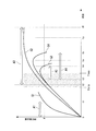
図3は、本実施形態に係る押圧検出値と押圧遷移時間T1と押圧継続時間T2との関係の一例を示す図である。図3のグラフにおいて、横軸に時刻を示し、縦軸に押圧検出値を示す。ここで、時刻T1minと時刻T1maxの間の時間が押圧遷移時間T1である。
また、押圧検出値が押圧検出値の閾値P越えた時刻から所定の時刻txまでの時間が押圧継続時間T2の閾値の下限の時間T2minであり、押圧検出値が押圧検出値の閾値P越えた時刻から所定の時刻tyまでの時間が押圧継続時間T2の閾値の上限の時間T2maxである。
最初に、押圧検出特性G1について説明する。押圧検出特性G1では、時刻が0で押圧検出値が押圧力の非接触時の値(例えば、零)であったものが、時刻の経過とともに押圧検出値が増大し、時刻t1において押圧検出値が押圧検出値の閾値Pに達し、それ以後も増大を続ける。したがって、押圧判定部10341は、第1の判定を有効とする。
本実施形態においては、押圧センサ部101への一時的なユーザの体の一部や物体の接触によるユーザの意図しないタッチパネル102への信号の入力を有効にすることを防止するために、押圧遷移時間T1に条件、押圧遷移時間T1の閾値の下限T1minと、該閾値の上限T1maxとを設定する。押圧遷移時間T1は、例えば、0.5秒である。
また、押圧検出値が押圧検出値の閾値P越えた時刻から所定の時刻txまでの時間が押圧継続時間T2の閾値の下限の時間T2minであり、押圧検出値が押圧検出値の閾値P越えた時刻から所定の時刻tyまでの時間が押圧継続時間T2の閾値の上限の時間T2maxである。
最初に、押圧検出特性G1について説明する。押圧検出特性G1では、時刻が0で押圧検出値が押圧力の非接触時の値(例えば、零)であったものが、時刻の経過とともに押圧検出値が増大し、時刻t1において押圧検出値が押圧検出値の閾値Pに達し、それ以後も増大を続ける。したがって、押圧判定部10341は、第1の判定を有効とする。
本実施形態においては、押圧センサ部101への一時的なユーザの体の一部や物体の接触によるユーザの意図しないタッチパネル102への信号の入力を有効にすることを防止するために、押圧遷移時間T1に条件、押圧遷移時間T1の閾値の下限T1minと、該閾値の上限T1maxとを設定する。押圧遷移時間T1は、例えば、0.5秒である。
押圧検出特性G1では、押圧検出値が押圧検出値の閾値Pに到達するまで、時間A1を要しているが、時間A1の上限である時刻t1は、押圧遷移時間T1の閾値の下限T1minに達していない。したがって、押圧遷移時間判定部10342は、第2の判定を無効とする。この場合、ユーザの体の一部などが押圧センサ部101に一時的に接触しているとみなし、判定部1034は、接触検出部1032への信号の入力を無効にすると判定する。
次に、押圧検出特性G2では、時刻が0で押圧検出値が零であったものが、時間の経過とともに押圧検出値が増大し、時刻t2において押圧検出値の閾値Pに達している。したがって、押圧判定部10341は、第1の判定を有効とする。また、時刻0から時刻t2までの時間は、押圧遷移時間T1の条件の範囲内である。すなわち、押圧遷移時間判定部10342は、押圧遷移時間T1に関する第2の判定を行い、その結果、信号の入力を有効にすると判定する。
また、押圧検出特性G2では、押圧検出値が押圧検出値の閾値Pに到達した時刻t2以降、時刻t6まで押圧センサ部101が押圧検出値の閾値P以上の押圧検出値を検出している。
また、押圧検出特性G2では、押圧検出値が押圧検出値の閾値Pに到達した時刻t2以降、時刻t6まで押圧センサ部101が押圧検出値の閾値P以上の押圧検出値を検出している。
押圧検出特性G2において、時刻t2から時刻t6までの時間A3が、押圧継続時間となる。しかし、時間A3は、押圧継続時間T2の閾値の下限の時間T2minを越えて、押圧継続時間T1の条件を満たすが、該閾値の上限の時間T2maxに納まらずに、押圧継続時間T2の上限の時間T2maxを越えている。したがってこの場合は、電子機器100は、ユーザによって正常に把持され続けているとみなして、押圧継続時間判定部10343は、時間A3に対して第3の判定を行い、その結果、タッチパネル102から接触検出部1032への信号の入力を無効にすると判定する。
次に、押圧検出特性G3では、時刻が0で押圧検出値が零であったものが、時刻の経過とともに押圧検出値が増大し、時刻t3において押圧検出値が押圧検出値の閾値Pに達している。したがって、押圧判定部10341は、第1の判定を有効とする。この時、時刻0から時刻t3までの時間は、押圧遷移時間T1の範囲内である。すなわち、押圧遷移時間判定部10342は、押圧遷移時間T1に関する第2の判定を行い、その結果、タッチパネル102から接触検出部1032への信号の入力を有効にすると判定する。そして、押圧センサ部101は、押圧検出値が押圧検出値の閾値Pに到達した時刻t3以降、押圧検出値の閾値P以下になる時刻t4までの時間A2において、押圧検出値の閾値P以上の押圧検出値を検出し続けている。
しかし、時間A2は、押圧継続時間T2の閾値の下限の時間T2minを満たしていない。すなわち、押圧継続時間判定部10343は、時間A2に対して第3の判定を行い、その結果、タッチパネル102から接触検出部1032への信号の入力を有効にしないと判定する。
しかし、時間A2は、押圧継続時間T2の閾値の下限の時間T2minを満たしていない。すなわち、押圧継続時間判定部10343は、時間A2に対して第3の判定を行い、その結果、タッチパネル102から接触検出部1032への信号の入力を有効にしないと判定する。
次に、押圧検出特性G4では、時刻が0で押圧検出値が零であったものが、時刻の経過とともに押圧検出値が増大し、時刻t3において押圧検出値が押圧検出値の閾値Pに達している。したがって、押圧判定部10341は、第1の判定を有効とする。また、時刻0から時刻t3までの時間は、押圧遷移時間T1の範囲内にある。押圧遷移時間判定部10342は、押圧遷移時間T1に関する第2の判定を行い、接触検出部1032へのタッチパネル102からの信号の入力を有効にすると判定する。押圧センサ部101は、押圧検出値を時刻t3以降、時刻t5までの時間A4において、押圧検出値の閾値Pであるかそれを越えて検出している。例えば、押圧継続時間T2の閾値の下限の時間をG4における押圧検出値が押圧検出値の閾値Pに達した時刻t3から時刻txまでの時間とし、該時刻t3から時刻tyまでの時間が押圧継続時間T2の閾値の上限の時間とした場合、押圧検出特性G4は、押圧継続時間T2の閾値の下限の時間T1minを越えており、かつ該閾値の上限の時間T2max以内である。ゆえに、押圧継続時間判定部10343は、時間A4に対して第3の判定を行い、その結果、接触検出部1032へのタッチパネル102からの信号の入力を有効にすると判定する。
このように、判定部1034は、押圧検出特性G4において、第1の判定、第2の判定、第3の判定を行い、いずれも接触検出部1032へのタッチパネル102からの信号の入力を有効にすると判定した場合、接触検出部1032へのタッチパネル102からの信号の入力を検出切替設定部1031に有効にさせる。一方、判定部1034は、第1の判定、第2の判定、第3の判定のうちいずれかで信号の入力を有効にしないと判定した場合、接触検出部1032へのタッチパネル102からの信号の入力を検出切替設定部1031に無効にさせる。
なお、本実施形態において、押圧遷移時間T1は、閾値の下限T1minおよび閾値の上限T1maxの条件を設けているが、該閾値の下限T1minの条件のみを用いてもよい。また、押圧継続時間T2は、閾値の下限の時間T2minおよび閾値の上限の時間T2maxの条件を設けているが、閾値の上限の時間T2maxのみを用いてもよい。
図4は、本実施形態に係る判定部1034の動作の一例を示すフローチャートである。
ステップST101において、判定部1034は、検出切替設定部1031が、接触検出部1032へのタッチパネル102からの信号の入力を無効に設定中か否かを判定する。信号の入力を無効に設定中である場合(YESの場合)、ステップST102以降の動作を行う。一方、無効に設定中でない場合、すなわち、有効に設定中の場合(NOの場合)、ステップST101に戻る。
ステップST102において、押圧判定部10341は、押圧センサ部101から押圧検出値を取得する。
ステップST103において、押圧判定部10341は、押圧センサ部101が検出した押圧検出値が非接触時の値(例えば、押圧検出値が零)以上か否かを判定する。押圧検出値が非接触時の値以上の場合(YESの場合)、押圧判定部10341は、押圧力の印加が開始されたと判定し、ステップST104に進む。一方、押圧検出値が非接触時の値未満の場合(NOの場合)、押圧判定部10341は、押圧力の印加が開始されていないと判定し、ステップST102に戻る。
ステップST101において、判定部1034は、検出切替設定部1031が、接触検出部1032へのタッチパネル102からの信号の入力を無効に設定中か否かを判定する。信号の入力を無効に設定中である場合(YESの場合)、ステップST102以降の動作を行う。一方、無効に設定中でない場合、すなわち、有効に設定中の場合(NOの場合)、ステップST101に戻る。
ステップST102において、押圧判定部10341は、押圧センサ部101から押圧検出値を取得する。
ステップST103において、押圧判定部10341は、押圧センサ部101が検出した押圧検出値が非接触時の値(例えば、押圧検出値が零)以上か否かを判定する。押圧検出値が非接触時の値以上の場合(YESの場合)、押圧判定部10341は、押圧力の印加が開始されたと判定し、ステップST104に進む。一方、押圧検出値が非接触時の値未満の場合(NOの場合)、押圧判定部10341は、押圧力の印加が開始されていないと判定し、ステップST102に戻る。
ステップST104において、押圧判定部10341は、押圧検出値が押圧検出値の閾値P以上であるか否かを判定する。押圧検出値が押圧検出値の閾値P以上である場合(YESの場合)、ステップST107へ進む。一方、押圧検出値が押圧検出値の閾値P未満である場合(NOの場合)、ステップST105に進む。
ステップST105において、押圧判定部10341は、押圧検出値が非接触時の値か否かを判定する。押圧検出値が非接触時の値の場合(YESの場合)、押圧判定部10341は、押圧力の印加が解除されたと判定して、ステップST102に戻る。一方、押圧検出値が非接触時の値を超えている場合(NOの場合)、押圧判定部10341は、押圧力の印加が継続されていると判定し、ステップST106に進み、押圧遷移時間判定部10342は、押圧遷移時間T1の計測を開始し、一定時間Δtの経過後、ステップST104に戻る。
ステップST107において、押圧遷移時間判定部10342は、押圧検出値が押圧力の印加が開始された時刻から押圧検出値の閾値Pを越えるまでの時間が押圧遷移時間T1の範囲内か否かを判定する。
ステップST105において、押圧判定部10341は、押圧検出値が非接触時の値か否かを判定する。押圧検出値が非接触時の値の場合(YESの場合)、押圧判定部10341は、押圧力の印加が解除されたと判定して、ステップST102に戻る。一方、押圧検出値が非接触時の値を超えている場合(NOの場合)、押圧判定部10341は、押圧力の印加が継続されていると判定し、ステップST106に進み、押圧遷移時間判定部10342は、押圧遷移時間T1の計測を開始し、一定時間Δtの経過後、ステップST104に戻る。
ステップST107において、押圧遷移時間判定部10342は、押圧検出値が押圧力の印加が開始された時刻から押圧検出値の閾値Pを越えるまでの時間が押圧遷移時間T1の範囲内か否かを判定する。
ステップST107において、押圧検出値が押圧検出値の閾値Pを越えている時間が押圧遷移時間T1の範囲内である場合(YESの場合)、ステップST109に進み、押圧継続時間判定部10343は、押圧継続時間の計測を開始し、一定時間Δtの経過後、ステップST110に進む。一方、ステップST107において、押圧検出値が押圧検出値の閾値Pを越えている時間が押圧遷移時間T1の範囲内でない場合(NOの場合)、ステップST108に進み、押圧遷移時間判定部10342は、押圧遷移時間T1の計測タイマをリセットする。
ステップST110において、押圧判定部10341は、押圧検出値が押圧検出値の閾値P未満であるか否かを判定する。
押圧検出値が押圧検出値の閾値P未満である場合(YESの場合)、ステップST112に進む。押圧検出値が押圧検出値の閾値P未満でない場合(NOの場合)、ステップST111に進む。
押圧検出値が押圧検出値の閾値P未満である場合(YESの場合)、ステップST112に進む。押圧検出値が押圧検出値の閾値P未満でない場合(NOの場合)、ステップST111に進む。
ステップST111において、ステップST107からステップST111の時間が押圧継続時間T2の閾値の上限の時間T2max以上である場合(YESの場合)、押圧継続時間判定部10343は、押圧継続時間が押圧継続時間T2の閾値を超えたと判定し、ステップST108に進み、計測タイマをリセットし、次いでステップST102に戻る。一方、ステップST107からステップST111の時間が押圧継続時間T2の閾値の上限の時間T2max以上でない場合(NOの場合)、ステップST109に戻る。
ステップST112において、ステップST107からステップST112の時間が押圧継続時間T2の閾値の下限の時間T2minおよび該閾値の上限の時間T2maxの範囲内である場場合(YESの場合)、ステップST113に進む。
ステップST113において、判定部1034は、検出切替設定部1031に接触検出部1032へのタッチパネルからの信号の入力を有効にさせる。一方、ステップST112において、ステップST107からステップST112の時間が押圧継続時間T2の閾値の下限T2minおよび該閾値の上限T2maxの範囲内でない場合、押圧継続時間判定部10343は、押圧継続時間が押圧継続時間T2の閾値未満であると判定し、ステップST108に進み、押圧継続時間判定部10343は、計測タイマをリセットし、ステップST102に戻る。
ステップST112において、ステップST107からステップST112の時間が押圧継続時間T2の閾値の下限の時間T2minおよび該閾値の上限の時間T2maxの範囲内である場場合(YESの場合)、ステップST113に進む。
ステップST113において、判定部1034は、検出切替設定部1031に接触検出部1032へのタッチパネルからの信号の入力を有効にさせる。一方、ステップST112において、ステップST107からステップST112の時間が押圧継続時間T2の閾値の下限T2minおよび該閾値の上限T2maxの範囲内でない場合、押圧継続時間判定部10343は、押圧継続時間が押圧継続時間T2の閾値未満であると判定し、ステップST108に進み、押圧継続時間判定部10343は、計測タイマをリセットし、ステップST102に戻る。
本実施形態によれば、電子機器100は、外部から押されることによって生じる押圧力を検出する押圧センサ部101と、操作体が接触する接触位置に応じた信号を出力するタッチパネル102と、押圧センサ部101から操作体が押圧センサ部101へ非接触時の押圧力から押圧力の閾値に達するまでの押圧遷移時間を取得し、取得した押圧遷移時間に基づいて、タッチパネル102から出力される信号を有効とするか否かを判定する判定部1034と、を備える。
これにより、電子機器100は、誤動作を確実に防止することができ、ユーザの利便性を向上できる。
これにより、電子機器100は、誤動作を確実に防止することができ、ユーザの利便性を向上できる。
(第2の実施形態)
以下、図面を参照しながら本発明の第2の実施形態について詳しく説明する。
第1の実施形態において押圧センサ部101が電子機器100の筐体10の右側面に備えられる場合について説明した。本実施形態においては、押圧センサ部101Aが電子機器100Aの筐体10Aの左側面に設けられる場合について説明する。
図5A~図5Cは、本発明の第2の実施形態に係る電子機器100Aの外観の一例を示す外観図である。図5Aは、電子機器100Aの左側面図、図5Bは、正面図、図5Cは、右側面図である。
以下、図面を参照しながら本発明の第2の実施形態について詳しく説明する。
第1の実施形態において押圧センサ部101が電子機器100の筐体10の右側面に備えられる場合について説明した。本実施形態においては、押圧センサ部101Aが電子機器100Aの筐体10Aの左側面に設けられる場合について説明する。
図5A~図5Cは、本発明の第2の実施形態に係る電子機器100Aの外観の一例を示す外観図である。図5Aは、電子機器100Aの左側面図、図5Bは、正面図、図5Cは、右側面図である。
図5A~図5Cに示すように、電子機器100Aの前面には、タッチパネル102が備えられる。
タッチパネル102の左側面には、押圧センサ部101Aが設けられる。なお、押圧センサ部101Aの設置位置以外は、第1の実施形態と同様であるため、説明は省略する。
このように、本実施形態によれば、第1の実施形態と同様の効果を得ることができる。
タッチパネル102の左側面には、押圧センサ部101Aが設けられる。なお、押圧センサ部101Aの設置位置以外は、第1の実施形態と同様であるため、説明は省略する。
このように、本実施形態によれば、第1の実施形態と同様の効果を得ることができる。
(第3の実施形態)
以下、図面を参照しながら本発明の第3の実施形態について詳しく説明する。
第1の実施形態において、押圧センサ部101が電子機器100の筐体10の右側面に備えられる場合について説明した。本実施形態においては、押圧センサ部101、101Aが電子機器100Bの筐体10Bの両側面に設けられる場合について説明する。
図6A~図6Cは、本発明の第3の実施形態に係る電子機器100Bの外観の一例を示す外観図である。図6Aは、左側面図、図6Bは、正面図、図6Cは、右側面図である。
以下、図面を参照しながら本発明の第3の実施形態について詳しく説明する。
第1の実施形態において、押圧センサ部101が電子機器100の筐体10の右側面に備えられる場合について説明した。本実施形態においては、押圧センサ部101、101Aが電子機器100Bの筐体10Bの両側面に設けられる場合について説明する。
図6A~図6Cは、本発明の第3の実施形態に係る電子機器100Bの外観の一例を示す外観図である。図6Aは、左側面図、図6Bは、正面図、図6Cは、右側面図である。
図6A~図6Cに示されるように、電子機器100Bの前面には、タッチパネル102が備えられる。タッチパネル102の両側面に押圧センサ部101、101Aが設けられる。ユーザは、例えば、押圧センサ部101または101Aのどちらかの押圧センサ部を利き手などに合わせて有効にする。なお、押圧センサ部101、101Aの設置位置以外は、第1の実施形態と同様であるため、説明は省略する。
このように、本実施形態によれば、第1の実施形態と同様の効果を得ることができる。
さらに、ユーザが押圧センサ部101または101Aのどちらかを有効にするかを選択することができ、電子機器100Bは、ユーザの利き手が左右どちらであっても押圧力によって誤動作を確実に防止することができ、ユーザの利便性を向上できる。
このように、本実施形態によれば、第1の実施形態と同様の効果を得ることができる。
さらに、ユーザが押圧センサ部101または101Aのどちらかを有効にするかを選択することができ、電子機器100Bは、ユーザの利き手が左右どちらであっても押圧力によって誤動作を確実に防止することができ、ユーザの利便性を向上できる。
このように、各実施形態において、外部から押されることによって生じる押圧力を検出する押圧センサ部101、101Aと、操作体が接触する接触位置に応じた信号を出力するタッチパネル102と、押圧センサ部101、101Aから操作体が押圧センサ部101、101Aへ非接触時の押圧力から押圧力の閾値に達するまでの押圧遷移時間を取得し、取得した押圧遷移時間に基づいて、タッチパネル102から出力される信号を有効とするか否かを判定する判定部1034と、を備える。
判定部1034は、押圧センサ部101、101Aが押圧力の閾値以上の押圧力を検出し続けている押圧継続時間を取得し、取得した押圧遷移時間と、押圧継続時間とに基づいて、タッチパネル102から出力される信号を有効とするか否かを判定する。
判定部1034は、押圧センサ部101、101Aが検出した押圧力と、押圧遷移時間と、押圧継続時間と、押圧力に関する情報とに基づいて、タッチパネル102から出力される信号を有効とするか否かを判定し、押圧力に関する情報は、押圧力の閾値に関する情報と、押圧遷移時間の閾値に関する情報と、押圧継続時間の閾値に関する情報とである。
判定部1034は、押圧センサ部101、101Aが検出した押圧力と、押圧遷移時間T1と、押圧継続時間T2と、押圧力に関する情報とに基づいて、タッチパネル102から出力される信号を有効とするか否かを判定する。
押圧力に関する情報は、押圧力の閾値Pに関する情報と、押圧遷移時間T1の閾値に関する情報と、押圧継続時間T2の閾値に関する情報と、である。
押圧センサ部101、101Aは、電子機器100、100A、100Bの側面に位置する。
判定部1034は、タッチパネル102に所定時間、操作体が接触しないことを検出すると、信号を無効とする。
電子機器操作制御方法は、外部から押されることによって生じる押圧力を検出する検出ステップと、操作体が接触する接触位置に応じた信号を出力する出力ステップと、検出ステップにおいて検出された押圧力に基づいて、出力ステップにおいて出力される信号を有効とするか否かを判定する判定ステップと、を有する。
電子機器操作制御プログラムは、外部から押されることによって生じる押圧力を検出する押圧センサ部101、101Aと、操作体が接触する接触位置に応じた信号を出力するタッチパネル102と、を備える電子機器100、100A、100Bに、押圧センサ部101、101Aで検出された押圧力に基づいて、タッチパネル102から出力される信号を有効とするか否かを判定する判定ステップを実行させる。
なお、上述した実施形態では、一例として携帯端末について説明したが、本発明はこれに限定されず、タッチパネルを備えるタブレット端末、PDA、パーソナルコンピュータなどでもよく、タッチパネルを備える電子機器であればよい。
なお、上述した実施形態における電子機器100、100A、100Bの一部、または全部をコンピュータで実現するようにしても良い。その場合、この制御機能を実現するためのプログラムをコンピュータ読み取り可能な記録媒体に記録して、この記録媒体に記録されたプログラムをコンピュータシステムに読み込ませ、実行することによって実現しても良い。なお、ここでいう「コンピュータシステム」とは、電子機器100、100A、100Bに内蔵されたコンピュータシステムであって、OSや周辺機器等のハードウェアを含むものとする。
また、「コンピュータ読み取り可能な記録媒体」とは、フレキシブルディスク、光磁気ディスク、ROM、CD-ROM等の可搬媒体、コンピュータシステムに内蔵されるハードディスク等の記憶装置のことをいう。さらに「コンピュータ読み取り可能な記録媒体」とは、インターネット等のネットワークや電話回線等の通信回線を介してプログラムを送信する場合の通信線のように、短時間、動的にプログラムを保持するもの、その場合のサーバやクライアントとなるコンピュータシステム内部の揮発性メモリのように、一定時間プログラムを保持しているものも含んでも良い。
また上記プログラムは、前述した機能の一部を実現するためのものであっても良く、さらに前述した機能をコンピュータシステムにすでに記録されているプログラムとの組み合わせで実現できるものであっても良い。
また、上述した実施形態における電子機器100、100A、100Bの一部、または全部を、LSI(Large Scale Integration)等の集積回路として実現しても良い。電子機器100、100A、100Bの各機能ブロックは個別にプロセッサ化してもよいし、一部、または全部を集積してプロセッサ化しても良い。また、集積回路化の手法はLSIに限らず専用回路、または汎用プロセッサで実現しても良い。また、半導体技術の進歩によりLSIに代替する集積回路化の技術が出現した場合、当該技術による集積回路を用いても良い。
以上、図面を参照してこの発明の一実施形態について詳しく説明してきたが、具体的な構成は上述のものに限られることはなく、この発明の要旨を逸脱しない範囲内において様々な設計変更等をすることが可能である。
本発明は、電子機器の誤動作を確実に防止し、ユーザの利便性を向上させることが必要な電子機器、および電子機器操作制御プログラムなどに適用することができる。
100、100A、100B・・・電子機器、10、10A、10B・・・筐体、101、101A・・・押圧センサ部、102・・・タッチパネル、103・・・制御部、1031・・・検出切替設定部、1032・・・接触検出部、1033・・・操作制御部、1034・・・判定部、10341・・・押圧判定部、10342・・・押圧遷移時間判定部、10343・・・押圧継続時間判定部、1035・・・押圧情報記憶部
Claims (5)
- 外部から押されることによって生じる押圧力を検出する押圧センサ部と、
操作体が接触する接触位置に応じた信号を出力するタッチパネルと、
前記押圧センサ部から前記操作体が前記押圧センサ部へ非接触時の前記押圧力から押圧力の閾値に達するまでの押圧遷移時間を取得し、取得した前記押圧遷移時間に基づいて、前記タッチパネルから出力される前記信号を有効とするか否かを判定する判定部と、
を備える電子機器。 - 前記判定部は、
前記押圧センサ部から前記押圧センサ部が前記押圧力の閾値以上の前記押圧力を検出し続けている押圧継続時間を取得し、取得した前記押圧遷移時間と、前記押圧継続時間とに基づいて、前記タッチパネルから出力される前記信号を有効とするか否かを判定する請求項1に記載の電子機器。 - 前記判定部は、
前記押圧センサ部が検出した前記押圧力と、前記押圧遷移時間と、前記押圧継続時間と、押圧力に関する情報とに基づいて、前記タッチパネルから出力される前記信号を有効とするか否かを判定し、
前記押圧力に関する情報は、
前記押圧力の閾値に関する情報と、前記押圧遷移時間の閾値に関する情報と、前記押圧継続時間の閾値に関する情報とである請求項2に記載の電子機器。 - 前記押圧センサ部は、前記電子機器の側面に位置する請求項1から請求項3のいずれか一項に記載の電子機器。
- 外部から押されることによって生じる押圧力を検出する押圧センサ部と、操作体が接触する接触位置に応じた信号を出力するタッチパネルと、を備える電子機器に、
前記押圧センサ部で検出された前記押圧力に基づいて、前記タッチパネルから出力される前記信号を有効とするか否かを判定する判定ステップを実行させるための電子機器操作制御プログラム。
Applications Claiming Priority (2)
| Application Number | Priority Date | Filing Date | Title |
|---|---|---|---|
| JP2013010911A JP6089317B2 (ja) | 2013-01-24 | 2013-01-24 | 電子機器、および電子機器操作制御プログラム |
| JP2013-010911 | 2013-01-24 |
Publications (1)
| Publication Number | Publication Date |
|---|---|
| WO2014115808A1 true WO2014115808A1 (ja) | 2014-07-31 |
Family
ID=51227597
Family Applications (1)
| Application Number | Title | Priority Date | Filing Date |
|---|---|---|---|
| PCT/JP2014/051387 Ceased WO2014115808A1 (ja) | 2013-01-24 | 2014-01-23 | 電子機器、および電子機器操作制御プログラム |
Country Status (2)
| Country | Link |
|---|---|
| JP (1) | JP6089317B2 (ja) |
| WO (1) | WO2014115808A1 (ja) |
Cited By (2)
| Publication number | Priority date | Publication date | Assignee | Title |
|---|---|---|---|---|
| CN111630479A (zh) * | 2018-01-31 | 2020-09-04 | 三菱电机株式会社 | 触摸面板装置 |
| EP3767444A1 (en) * | 2019-07-12 | 2021-01-20 | Alpine Electronics, Inc. | Input detection device and input detection method |
Families Citing this family (6)
| Publication number | Priority date | Publication date | Assignee | Title |
|---|---|---|---|---|
| JP2016081207A (ja) * | 2014-10-15 | 2016-05-16 | シャープ株式会社 | 端末装置、及びプログラム |
| DE112018003675T5 (de) | 2017-07-20 | 2020-05-14 | Sony Corporation | Informationsverarbeitungseinrichtung, informationsverarbeitungsverfahren und programm |
| KR20190027553A (ko) * | 2017-09-07 | 2019-03-15 | 주식회사 하이딥 | 측면에 터치 압력 감지부를 구비한 휴대용 단말기 |
| JP6491368B1 (ja) * | 2018-01-10 | 2019-03-27 | 東芝エレベータ株式会社 | 操作判定装置、操作判定方法およびプログラム |
| JP7305528B2 (ja) | 2019-12-04 | 2023-07-10 | アルパイン株式会社 | 押下検出装置および押下検出方法 |
| JP2023083850A (ja) * | 2021-12-06 | 2023-06-16 | 株式会社東海理化電機製作所 | 制御装置、操作装置、およびシステム |
Citations (5)
| Publication number | Priority date | Publication date | Assignee | Title |
|---|---|---|---|---|
| JPH06332607A (ja) * | 1993-05-19 | 1994-12-02 | Mitsubishi Electric Corp | 表示一体型入力装置 |
| JP2006011591A (ja) * | 2004-06-23 | 2006-01-12 | Denso Corp | 個人認証システム |
| JP2008544352A (ja) * | 2005-06-08 | 2008-12-04 | スリーエム イノベイティブ プロパティズ カンパニー | 多数のタッチ位置法を含むタッチ位置決定方法 |
| JP2010044567A (ja) * | 2008-08-12 | 2010-02-25 | Sony Corp | 情報処理装置 |
| WO2011034310A2 (en) * | 2009-09-21 | 2011-03-24 | Samsung Electronics Co., Ltd. | Input method and input device of portable terminal |
Family Cites Families (6)
| Publication number | Priority date | Publication date | Assignee | Title |
|---|---|---|---|---|
| US20080105470A1 (en) * | 2004-08-02 | 2008-05-08 | Koninklijke Philips Electronics, N.V. | Touch Screen Slider for Setting Floating Point Value |
| WO2011077525A1 (ja) * | 2009-12-24 | 2011-06-30 | 富士通株式会社 | 電子機器、操作検出方法及び操作検出プログラム |
| US8432368B2 (en) * | 2010-01-06 | 2013-04-30 | Qualcomm Incorporated | User interface methods and systems for providing force-sensitive input |
| JP5573487B2 (ja) * | 2010-08-20 | 2014-08-20 | ソニー株式会社 | 情報処理装置、プログラム及び操作制御方法 |
| US9798408B2 (en) * | 2011-05-27 | 2017-10-24 | Kyocera Corporation | Electronic device |
| WO2012164883A1 (ja) * | 2011-05-27 | 2012-12-06 | 京セラ株式会社 | 電子機器 |
-
2013
- 2013-01-24 JP JP2013010911A patent/JP6089317B2/ja not_active Expired - Fee Related
-
2014
- 2014-01-23 WO PCT/JP2014/051387 patent/WO2014115808A1/ja not_active Ceased
Patent Citations (5)
| Publication number | Priority date | Publication date | Assignee | Title |
|---|---|---|---|---|
| JPH06332607A (ja) * | 1993-05-19 | 1994-12-02 | Mitsubishi Electric Corp | 表示一体型入力装置 |
| JP2006011591A (ja) * | 2004-06-23 | 2006-01-12 | Denso Corp | 個人認証システム |
| JP2008544352A (ja) * | 2005-06-08 | 2008-12-04 | スリーエム イノベイティブ プロパティズ カンパニー | 多数のタッチ位置法を含むタッチ位置決定方法 |
| JP2010044567A (ja) * | 2008-08-12 | 2010-02-25 | Sony Corp | 情報処理装置 |
| WO2011034310A2 (en) * | 2009-09-21 | 2011-03-24 | Samsung Electronics Co., Ltd. | Input method and input device of portable terminal |
Cited By (4)
| Publication number | Priority date | Publication date | Assignee | Title |
|---|---|---|---|---|
| CN111630479A (zh) * | 2018-01-31 | 2020-09-04 | 三菱电机株式会社 | 触摸面板装置 |
| US11079891B2 (en) * | 2018-01-31 | 2021-08-03 | Mitsubishi Electric Corporation | Touch screen device |
| CN111630479B (zh) * | 2018-01-31 | 2024-03-19 | 三菱电机株式会社 | 触摸面板装置 |
| EP3767444A1 (en) * | 2019-07-12 | 2021-01-20 | Alpine Electronics, Inc. | Input detection device and input detection method |
Also Published As
| Publication number | Publication date |
|---|---|
| JP2014142813A (ja) | 2014-08-07 |
| JP6089317B2 (ja) | 2017-03-08 |
Similar Documents
| Publication | Publication Date | Title |
|---|---|---|
| JP6089317B2 (ja) | 電子機器、および電子機器操作制御プログラム | |
| JP4994489B2 (ja) | タッチパネル装置 | |
| KR101517136B1 (ko) | 터치 조작 처리 방법 및 단말 장치 | |
| CN106406904B (zh) | 一种信息处理方法、电子设备及信息处理装置 | |
| JP5730866B2 (ja) | 情報入力装置、情報入力方法及びプログラム | |
| KR20190064637A (ko) | 거짓 터치 방지 방법 및 단말 | |
| JP5222967B2 (ja) | 携帯端末 | |
| CN104364748A (zh) | 终端操作模式的切换和呈现方法及终端 | |
| CN103823624A (zh) | 信息处理的方法及电子设备 | |
| WO2009147779A1 (ja) | 携帯通信端末 | |
| US8928611B2 (en) | Touch sensor usability enhancement on clamshell notebook | |
| JP6182934B2 (ja) | 通信装置、およびプログラム | |
| JP6062519B1 (ja) | 電子機器及び電子機器の動作方法 | |
| WO2015156217A1 (ja) | 携帯端末装置 | |
| JP2017520179A5 (ja) | ||
| JP6551579B2 (ja) | 携帯端末及びプログラム | |
| JP6000035B2 (ja) | 情報処理装置、情報処理装置の制御方法、制御プログラム、および記録媒体 | |
| JP2015141595A (ja) | 電子機器および電子機器操作制御プログラム | |
| JP2015169948A (ja) | 情報処理装置、情報処理方法、及び情報処理プログラム | |
| JP2015022719A (ja) | 電子機器、制御方法および制御プログラム | |
| CN105930025B (zh) | 一种快捷截图方法及具有快捷截图功能的移动装置 | |
| JP6478094B2 (ja) | 携帯端末、切り替え方法、およびプログラム | |
| JP2017033030A (ja) | 情報処理装置 | |
| KR20190107554A (ko) | 모바일 단말을 위한 스마트 락 스크린 방법 및 모바일 단말 | |
| JP2013047864A (ja) | 情報入力装置、情報入力方法及びプログラム |
Legal Events
| Date | Code | Title | Description |
|---|---|---|---|
| 121 | Ep: the epo has been informed by wipo that ep was designated in this application |
Ref document number: 14743446 Country of ref document: EP Kind code of ref document: A1 |
|
| DPE2 | Request for preliminary examination filed before expiration of 19th month from priority date (pct application filed from 20040101) | ||
| NENP | Non-entry into the national phase |
Ref country code: DE |
|
| 122 | Ep: pct application non-entry in european phase |
Ref document number: 14743446 Country of ref document: EP Kind code of ref document: A1 |