WO2014115703A1 - Dispositif de traitement de cintrage sur chant d'un fil rectangulaire et procédé de traitement de cintrage sur chant d'un fil rectangulaire - Google Patents
Dispositif de traitement de cintrage sur chant d'un fil rectangulaire et procédé de traitement de cintrage sur chant d'un fil rectangulaire Download PDFInfo
- Publication number
- WO2014115703A1 WO2014115703A1 PCT/JP2014/051061 JP2014051061W WO2014115703A1 WO 2014115703 A1 WO2014115703 A1 WO 2014115703A1 JP 2014051061 W JP2014051061 W JP 2014051061W WO 2014115703 A1 WO2014115703 A1 WO 2014115703A1
- Authority
- WO
- WIPO (PCT)
- Prior art keywords
- bending
- flat wire
- pressing
- wire
- rectangular
- Prior art date
Links
- 238000005452 bending Methods 0.000 title claims abstract description 125
- 238000003672 processing method Methods 0.000 title 1
- 238000003825 pressing Methods 0.000 claims abstract description 109
- 230000002093 peripheral effect Effects 0.000 claims description 44
- 238000000034 method Methods 0.000 claims description 34
- 230000015572 biosynthetic process Effects 0.000 claims description 19
- 230000001105 regulatory effect Effects 0.000 claims description 9
- 238000010586 diagram Methods 0.000 description 4
- 239000011248 coating agent Substances 0.000 description 3
- 238000000576 coating method Methods 0.000 description 3
- 238000004519 manufacturing process Methods 0.000 description 3
- 230000006866 deterioration Effects 0.000 description 2
- XEEYBQQBJWHFJM-UHFFFAOYSA-N Iron Chemical group [Fe] XEEYBQQBJWHFJM-UHFFFAOYSA-N 0.000 description 1
- 238000003475 lamination Methods 0.000 description 1
- 238000003754 machining Methods 0.000 description 1
Images


Classifications
-
- H—ELECTRICITY
- H01—ELECTRIC ELEMENTS
- H01F—MAGNETS; INDUCTANCES; TRANSFORMERS; SELECTION OF MATERIALS FOR THEIR MAGNETIC PROPERTIES
- H01F41/00—Apparatus or processes specially adapted for manufacturing or assembling magnets, inductances or transformers; Apparatus or processes specially adapted for manufacturing materials characterised by their magnetic properties
- H01F41/02—Apparatus or processes specially adapted for manufacturing or assembling magnets, inductances or transformers; Apparatus or processes specially adapted for manufacturing materials characterised by their magnetic properties for manufacturing cores, coils, or magnets
- H01F41/04—Apparatus or processes specially adapted for manufacturing or assembling magnets, inductances or transformers; Apparatus or processes specially adapted for manufacturing materials characterised by their magnetic properties for manufacturing cores, coils, or magnets for manufacturing coils
- H01F41/06—Coil winding
- H01F41/071—Winding coils of special form
-
- B—PERFORMING OPERATIONS; TRANSPORTING
- B21—MECHANICAL METAL-WORKING WITHOUT ESSENTIALLY REMOVING MATERIAL; PUNCHING METAL
- B21F—WORKING OR PROCESSING OF METAL WIRE
- B21F1/00—Bending wire other than coiling; Straightening wire
-
- B—PERFORMING OPERATIONS; TRANSPORTING
- B21—MECHANICAL METAL-WORKING WITHOUT ESSENTIALLY REMOVING MATERIAL; PUNCHING METAL
- B21F—WORKING OR PROCESSING OF METAL WIRE
- B21F3/00—Coiling wire into particular forms
- B21F3/02—Coiling wire into particular forms helically
- B21F3/04—Coiling wire into particular forms helically externally on a mandrel or the like
-
- H—ELECTRICITY
- H01—ELECTRIC ELEMENTS
- H01F—MAGNETS; INDUCTANCES; TRANSFORMERS; SELECTION OF MATERIALS FOR THEIR MAGNETIC PROPERTIES
- H01F41/00—Apparatus or processes specially adapted for manufacturing or assembling magnets, inductances or transformers; Apparatus or processes specially adapted for manufacturing materials characterised by their magnetic properties
- H01F41/02—Apparatus or processes specially adapted for manufacturing or assembling magnets, inductances or transformers; Apparatus or processes specially adapted for manufacturing materials characterised by their magnetic properties for manufacturing cores, coils, or magnets
- H01F41/04—Apparatus or processes specially adapted for manufacturing or assembling magnets, inductances or transformers; Apparatus or processes specially adapted for manufacturing materials characterised by their magnetic properties for manufacturing cores, coils, or magnets for manufacturing coils
- H01F41/06—Coil winding
- H01F41/082—Devices for guiding or positioning the winding material on the former
-
- H—ELECTRICITY
- H02—GENERATION; CONVERSION OR DISTRIBUTION OF ELECTRIC POWER
- H02K—DYNAMO-ELECTRIC MACHINES
- H02K15/00—Methods or apparatus specially adapted for manufacturing, assembling, maintaining or repairing of dynamo-electric machines
- H02K15/04—Methods or apparatus specially adapted for manufacturing, assembling, maintaining or repairing of dynamo-electric machines of windings, prior to mounting into machines
- H02K15/0435—Wound windings
- H02K15/0442—Loop windings
- H02K15/045—Form wound coils
-
- H—ELECTRICITY
- H01—ELECTRIC ELEMENTS
- H01F—MAGNETS; INDUCTANCES; TRANSFORMERS; SELECTION OF MATERIALS FOR THEIR MAGNETIC PROPERTIES
- H01F17/00—Fixed inductances of the signal type
- H01F17/04—Fixed inductances of the signal type with magnetic core
- H01F17/045—Fixed inductances of the signal type with magnetic core with core of cylindric geometry and coil wound along its longitudinal axis, i.e. rod or drum core
- H01F2017/046—Fixed inductances of the signal type with magnetic core with core of cylindric geometry and coil wound along its longitudinal axis, i.e. rod or drum core helical coil made of flat wire, e.g. with smaller extension of wire cross section in the direction of the longitudinal axis
Definitions
- the present invention relates to a flat wire edgewise bending apparatus and a flat wire edgewise bending method used for a coil of a rotating electrical machine.
- the thickness of the processed portion increases compared to the strands.
- the increased portion of the plate thickness interferes with each other between the laminations, and causes a reduction in the coil space factor. Therefore, as a method of suppressing an increase in the thickness of the flat wire, after pressing the surface formed by the long side of the rectangular cross section of the flat wire with a deformation mechanism and deforming the flat wire to reduce the plate thickness in advance, A technique for bending is proposed (for example, Patent Document 1).
- Patent Document 1 the amount of increase in the thickness of the inner peripheral surface side of the bent portion is expected, and the thickness of the portion of the flat wire is reduced in advance by a deformation mechanism so as to decrease by the expected increase amount during processing. Let me. By doing so, after bending, the coil thickness of the bent part on the inner peripheral surface side when forming the coil is the same as the thickness of the strand, and the coil thickness of the inner peripheral surface side when forming the coil is kept constant Can be manufactured.
- the flat wire width is increased by the flat wire thickness reduction processing by the deformation mechanism, and the coil outer peripheral surface side is greatly extended in the longitudinal direction by the subsequent bending processing, and as a result, the insulating film of the flat wire is extended in both directions. There was a problem that the performance of the insulating film deteriorated.
- the present invention has been made to solve the above-described problems, and a flat wire edgewise bending apparatus and a flat wire edge in which the plate thickness of the edgewise bending portion of the flat wire does not swell compared to the strand.
- An object is to provide a wise bending method.
- the flat wire edgewise bending apparatus is: One surface formed by the long side of the rectangular section of the rectangular wire is the first surface, the surface opposite to the first surface is the second surface, and the surface formed by the short side of the rectangular section of the rectangular wire is formed at the time of coil formation.
- a fixing member for fixing the straight portion of the flat wire In the rectangular wire edgewise bending machine to let A fixing member for fixing the straight portion of the flat wire;
- a rotatable cylindrical shaft having a rotation axis extending in the short side direction of a rectangular cross section of the rectangular wire, wherein the third surface is on the outer peripheral surface of the shaft, and the rotation axis of the shaft and the longitudinal direction of the rectangular wire are Shafts that come into contact with each other in a vertical relationship,
- a flange plate surface that is a flange attached to the shaft and holds the first surface;
- a bending tool provided with a bending guide protruding so as to contact the fourth surface in the same direction as the shaft from the flange surface;
- a pressing tool that presses the second surface against the flange while sandwiching the flat wire between the flange plate surface of the flange;
- the flat wire edgewise bending method according to the present invention is: One surface formed by the long side of the rectangular section of the rectangular wire is the first surface, the surface opposite to the first surface is the second surface, and the surface formed by the short side of the rectangular section of the rectangular wire is formed at the time of coil formation.
- a rectangular wire having a surface corresponding to the inner peripheral surface side on the third surface, the opposite side of the third surface and having a surface corresponding to the outer peripheral surface side as the fourth surface during coil formation
- the third surface is in contact with the outer peripheral surface of a rotatable cylindrical shaft whose rotation axis extends in the short side direction of the rectangular cross section of the flat wire,
- the rectangular wire is bent so that the third surface is along the outer peripheral surface of the shaft in a state where a part on the inner peripheral surface side when the coil of the flat wire is formed is pressed.
- the flat wire edgewise bending apparatus is: A fixing member for fixing the straight portion of the flat wire; A rotatable cylindrical shaft having a rotation axis extending in the short side direction of a rectangular cross section of the rectangular wire, wherein the third surface is on the outer peripheral surface of the shaft, and the rotation axis of the shaft and the longitudinal direction of the rectangular wire are Shafts that come into contact with each other in a vertical relationship, A flange plate surface that is a flange attached to the shaft and holds the first surface; A bending tool provided with a bending guide protruding so as to contact the fourth surface in the same direction as the shaft from the flange surface; Since it has a pressing tool that presses the second surface against the flange side by sandwiching the flat wire between the flange disk surface of the flange, By performing edgewise bending while pressing the surface formed by the long side of the rectangular cross section of the flat wire, an increase in the thickness of the bent portion on the inner peripheral surface side during coil formation can be suppressed.
- the width of the flat wire is constant in the longitudinal direction of the flat wire, and the rectangular wire can be accurately positioned in the short direction in edgewise bending, and the coil shape accuracy Can be improved. Furthermore, since the elongation in the longitudinal direction of the insulating film of the rectangular wire on the outer peripheral surface side during coil formation by edgewise bending is small, it is possible to suppress deterioration of the insulating performance.
- the flat wire edgewise bending method according to the present invention is: The third surface is in contact with the outer peripheral surface of a rotatable cylindrical shaft whose rotation axis extends in the short side direction of the rectangular cross section of the flat wire, Since it is a flat wire edgewise bending method in which a flat wire is bent so that the third surface is along the outer peripheral surface of the shaft in a state where a part of the inner peripheral surface side at the time of coil formation of the flat wire is pressed, By performing edgewise bending while pressing the surface formed by the long side of the rectangular cross section of the flat wire, an increase in the thickness of the bent portion on the inner peripheral surface side during coil formation can be suppressed.
- the width of the flat wire is constant in the longitudinal direction of the flat wire, and the rectangular wire can be accurately positioned in the short direction in edgewise bending, and the coil shape accuracy Can be improved. Furthermore, since the elongation in the longitudinal direction of the insulating film of the rectangular wire on the outer peripheral surface side during coil formation by edgewise bending is small, it is possible to suppress deterioration of the insulating performance.
- FIG. It is a figure which shows the structure of the flat wire edgewise bending apparatus which concerns on this Embodiment 1.
- FIG. It is a perspective view of the coil bent using the flat wire edgewise bending apparatus which concerns on this Embodiment 1.
- FIG. It is a perspective view of the stator of the rotary electric machine to which the coil which concerns on this Embodiment 1 was applied.
- It is sectional drawing of the fixing unit which concerns on this Embodiment 1.
- FIG. It is sectional drawing of the processing unit which concerns on this Embodiment 1.
- FIG. It is a perspective view of the bending tool which concerns on this Embodiment 1.
- FIG. It is a perspective view of the press member concerning this Embodiment 1.
- FIG. 8 It is a cross-sectional schematic diagram which shows the bending process of the flat wire which concerns on this Embodiment 1.
- FIG. It is sectional drawing which shows how to transmit the load by the pressing tool which concerns on this Embodiment 1.
- FIG. It is sectional drawing of the rectangular wire before the bending process in the general bending process which concerns on this Embodiment 1, and the rectangular line after a bending process.
- FIG. 1 is a diagram showing a configuration of a rectangular wire edgewise bending apparatus 100 (hereinafter referred to as a processing apparatus 100).
- FIG. 2 is a perspective view of the coil 10 manufactured by bending.
- FIG. 3 is a perspective view of the stator 20 of the rotating electrical machine to which the coil 10 is applied.
- the processing apparatus 100 includes five elements: an uncoiler 2, a strainer 3, a feed unit 4, a fixed unit 5, and a flat wire processing unit 6 (hereinafter referred to as a processing unit 6).
- the uncoiler 2 supplies a flat wire 1 wound around a bobbin and covered with an insulating film to a strainer 3.
- the strainer 3 extends the flat wire 1 supplied from the uncoiler 2 so as to smooth the surface formed by the long side of the rectangular cross section of the flat wire 1 and the surface formed by the short side.
- the feed unit 4 feeds the flat wire 1 smoothed by the strainer 3 to the fixed unit 5 by a certain amount.
- the fixed unit 5 grips the flat wire 1 sent from the feed unit 4.
- the processing unit 6 performs a bending process on the flat wire 1.
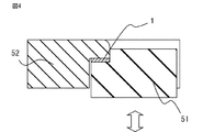
- FIG. 4 is a cross-sectional view of the fixing unit 5 taken along line AA in FIG.
- the fixed unit 5 (referred to as a fixed member in the claims) includes a fixed guide 52 and a lifting plate 51.
- the section of the fixed guide 52 that fixes the flat wire 1 has an L-shaped cross section.
- the lifting plate 51 having an L-shaped cross section rises from below, so that the flat wire 1 is surrounded and fixed. To do.
- FIG. 5 is a cross-sectional view of the processing unit 6.
- the processing unit 6 includes a bending tool 61 and a pressing tool 62.
- the bending tool 61 is a member for bending the flat wire 1 into a predetermined coil shape.
- the pressing tool 62 is a member that presses the flat wire 1 from below to above in FIG.
- FIG. 6A and 6B are perspective views of the bending tool 61.
- FIG. FIG. 6A and FIG. 6B are diagrams showing different viewpoints.
- the bending tool 61 includes a cylindrical shaft 61a extending in the short side direction of the rectangular cross section of the flat wire 1 and a flange 61b attached to the tip of the shaft 61a.
- the surface of the flange 61b in contact with the flange disk surface 61b1 is the first surface H
- the surface opposite to the first surface H is the second surface I
- the surface in contact with the shaft 61a is the third.
- the surface J and the opposite surface are the fourth surface K.
- the shaft 61a and the third surface J of the flat wire 1 are in contact with each other in a positional relationship in which the rotation axis of the shaft 61a and the longitudinal direction of the flat wire 1 are perpendicular to each other.
- the flange 61b includes a flange disk surface 61b1 that is in contact with the first surface H of the flat wire 1 and a bending guide 61b2 that protrudes in the same direction as the shaft 61a from the flange disk surface 61b1 and contacts the fourth surface K of the flat wire 1 in the surface.
- the pressing tool 62 shown in FIG. 5 includes a pressing member 62a, a wedge-shaped member 62b, a pressing guide 62c, and a rotating base 62d.
- a pressing guide 62c is placed on the rotary base 62d.
- the wedge-shaped member 62b can move forward and backward perpendicularly to the shaft 61a between the pressing member 62a and the pressing guide 62c.
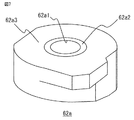
- FIG. 7 is a perspective view of the pressing member 62a.
- the pressing member 62a has a hole 62a1 into which the shaft 61a is inserted at the center, and a pressing surface 62a2 protruding in an annular shape is formed in a predetermined range around the hole 62a1.
- the pressing surface 62a2 presses the flat wire 1 with the flange surface 61b1 interposed therebetween.
- a step is provided from the pressing surface 62a2, and an out-of-plane deformation regulating surface 62a3 for regulating out-of-plane deformation generated on the outer peripheral surface side of the coil during bending of the flat wire 1 through a predetermined gap is provided.
- the relationship between the bending tool 61 and the pressing tool 62 will be described with reference to FIG.
- the shaft 61a of the bending tool 61 is inserted into the hole 62a1 of the pressing member 62a of the pressing tool 62, and is fixed to the rotary base 62d.
- the flange disk surface 61b1 of the bending tool 61 is positioned so as to face the pressing member 62a.
- a rotating device (not shown) is attached to the rotating base 62d. When the rotating device rotates, the bending tool 61 fixed to the rotating base rotates together with the rotating base 62d.
- the pressure guide 62c is placed on the rotary base 62d, and the wedge-shaped member 62b guided by the pressure guide 62c and the pressure member 62a that moves up and down along the slope of the tip of the wedge-shaped member 62b overlap. Yes. All the members of the pressing tool 62 rotate together with the bending tool 61 in accordance with the rotation of the rotating device. Since it is comprised in this way, the relative positional relationship of the bending tool 61 and the press tool 62 does not change with rotation of a rotation apparatus during a bending process.
- each step of bending the flat wire 1 will be described.
- the flat wire 1 is fed by the feed unit 4 between the cylindrical surface of the shaft 61a and the bending guide 61b2 facing the shaft 61a by a certain amount.
- the rectangular wire 1 is fixed from the periphery by the fixing unit 5 in the fixing step.
- the flat wire 1 is sandwiched between the bending tool 61 and the pressing tool 62 of the processing unit 6 by the pressing step.
- the pressing operation of the pressing tool 62 will be described with reference to FIG.
- the wedge-shaped member 62b is guided by the pressing guide 62c and inserted under the pressing member 62a, thereby pressing the flat wire 1 from the bottom to the top through the pressing member 62a.
- FIG. 8 is a cross-sectional view showing a state in which the flat wire 1 is pressed by the processing unit 6.
- FIG. 9A is an enlarged view of a portion where the flat wire 1 in FIG. 8 is pressed.
- FIG. 9B is an enlarged view of the periphery of the flat wire 1 in FIG.
- a region where the pressing tool 62 presses the flat wire 1 is a pressing surface 62 a 2 of the pressing tool 62.
- the out-of-plane deformation regulating surface 62a3 of the pressing tool 62 is stepped down from the pressing surface 62a2, and a gap is generated between the flat wire 1 and the out-of-plane deformation regulating surface 62a3. Do not press.
- the reason why only the pressing surface 62a2 is pressed by the pressing tool 62 is that if the pressing area is the entire surface of the flat wire 1, the flat wire 1 extends at the outer peripheral portion and the inner peripheral portion of the coil. This is because the ratio is greatly different, and there is a high possibility that the flat wire 1 is damaged during bending. Therefore, the area where the pressing tool 62 is pressed is set to the minimum necessary range.
- the pressing surface 62a2 applies a pressing force to the flat wire 1 such that the flat wire 1 can be rubbed to some extent. Although not shown, this pressing force can be adjusted according to the rectangular wire used.
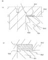
- FIG. 10 is a schematic sectional view showing a bending process of the flat wire 1.
- the processing apparatus 100 is cut so as to be parallel to the first surface H and the second surface I of the rectangular wire 1 within the range of the short side of the rectangular cross section of the rectangular wire 1, the rectangular wire 1 and the fixed unit 5 are cut.
- the cross section of the processing unit 6 is shown.
- the pressing tool 62 constituting the processing unit 6 is not actually cut, but is shown for convenience of explanation.
- FIG. 10A is a cross-sectional view showing a state before the bending process in which the flat wire 1 is fixed by the fixing unit 5 and the fourth surface K of the flat wire 1 is in contact with the bending guide 61b2.
- the flange disk surface 61b1 of the flange 61b is in contact with the first surface H of the flat wire 1.
- FIG. 10B is a cross-sectional view showing a state after the flat wire 1 is bent by the bending guide 61b2. In a state where the flat wire 1 is pressed by the pressing tool 62, the processing unit 6 rotates leftward.
- the flat wire 1 Since the area where the flat wire 1 is pressed is a small area of only the pressing surface 62a2, when the processing unit 6 rotates, the flat wire 1 slides moderately in the longitudinal direction with respect to the processing unit 6, and the processing unit 6 It is drawn toward the center of rotation.
- the flat wire 1 can be appropriately slipped to suppress unevenness in the extension in the longitudinal direction, and the reduction in the thickness of the flat wire 1 after bending can be made uniform. From the center of the flat wire 1 to the outer periphery during coil formation Damage to the insulating coating on the surface side can also be suppressed.
- the bending guide 61b2 pushes the fourth surface K of the flat wire 1 to cause plastic deformation, and the third surface J of the flat wire 1 is bent along the cylindrical surface of the shaft 61a.
- the processing apparatus 100 can form the coil 10 by bending the flat wire 1 one after another.
- FIG. 11 is a cross-sectional view showing how the load is transmitted by the pressing tool 62.
- the reaction force of the pressing load by the pressing tool 62 and the load that the flat wire 1 swells in the thickness direction are as follows: flat wire 1 ⁇ pressing member 62a ⁇ wedge member 62b ⁇ pressing guide 62c ⁇ rotating base 62d.
- FIG. 12A is a cross-sectional view showing a state of the flat wire 1 before bending in a general flat wire 1 bending process.
- the length (plate thickness) of the short side of the rectangular cross section of the flat wire 1 before bending is defined as 1a.
- FIG. 12B is a cross-sectional view showing a state of the flat wire 1 after bending in a general flat wire 1 bending process.
- the plate thickness on the inner peripheral surface side when the coil of the rectangular wire 1 after bending is formed is 1b, and the plate thickness on the outer peripheral surface side is 1c.
- FIG. 12A is a cross-sectional view showing a state of the flat wire 1 before bending in a general flat wire 1 bending process.
- the length (plate thickness) of the short side of the rectangular cross section of the flat wire 1 before bending is defined as 1a.
- FIG. 12B is a cross-sectional view showing a state of the flat wire 1 after bending in a general flat wire 1 bending process.
- FIG. 13 is a diagram showing changes in thickness of the flat wire 1 when the flat wire 1 is bent without pressing and when the flat wire 1 is pressed and bent.
- the plate thickness 1b of the flat wire 1 bent without pressing is increased by about 10% compared to the plate thickness 1a of the strand.
- the plate thickness 1c of the flat wire 1 bent without pressing is reduced by about 8% compared to the plate thickness 1a of the strand.
- the plate thickness 1b of the flat wire 1 pressed and bent in the range of the elastic region of the flat wire 1 is increased by about 8% compared to the plate thickness 1a of the strand.
- the thickness 1c of the flat wire 1 pressed and bent in the range of the elastic region of the flat wire 1 is reduced by about 8% compared to the thickness 1a of the strand.
- the plate thickness 1b of the flat wire 1 after processing is It returns to the same as the line thickness 1a.
- the plate thickness 1c of the flat wire 1 after processing is the plate of the wire. It is reduced by about 8% compared to the thickness 1a.
- the inner peripheral surface side thickness at the time of coil formation increases from the thickness of the element wire, and the outer peripheral surface side thickness at the time of coil formation is equal to the element wire. Less than the plate thickness.
- the flat wire 1 is bent while being plastically deformed by pressing the flat wire 1 by the processing unit 6 so that the plate thickness of the element wire is reduced by about 1%, the inner circumference when the coil of the flat wire 1 is formed.
- the plate thickness on the surface side is the same as the plate thickness of the strands.
- the processing apparatus 100 when the flat wire 1 is bent with the processing unit 6 pressing the inner peripheral surface side of the flat wire 1 in the plate thickness direction, the coil of the flat wire 1 is obtained. An increase in the thickness on the inner peripheral surface side during formation is suppressed.
- the processing apparatus 100 when the processing apparatus 100 is used, it is not necessary to pre-process the element wire in advance to reduce the thickness of the bent portion, and the surface formed by the long side of the rectangular cross section of the rectangular wire 1 is formed.
- the out-of-plane deformation of the rectangular wire can be regulated while suppressing an increase in the plate thickness on the inner peripheral surface side when the coil is formed by the bending process.
- the out-of-plane deformation regulating surface 62a3 of the pressing tool 62 is stepped down from the pressing surface 62a2, and the area where the flat wire 1 is pressed is a small area of only the pressing surface 62a2, so that the flat wire 1 is bent during bending.
- the unevenness of the extension in the longitudinal direction can be suppressed by sliding moderately in the longitudinal direction, and the reduction in the thickness of the flat wire 1 after bending can be made uniform.
- the damage given to the insulating film over can also be suppressed.
- Embodiment 2 the flat wire edgewise bending apparatus according to the second embodiment of the present invention will be described with reference to the drawings, focusing on the differences from the first embodiment.
- the first embodiment is different from the present embodiment in the shape of the pressing surface of the pressing member, and the other configuration is the same as that of the first embodiment.
- FIG. 14A is an enlarged view of a portion where the flat wire 1 is pressed by the processing unit 6.
- FIG. 14B is an enlarged view of the periphery of the flat wire 1 in FIG.
- a chamfer 262a21 is applied to the edge of the pressing surface 262a2 of the pressing member 62a to relax the edge of the edge of the pressing surface 262a2.
- the chamfer 262a21 is applied to the edge of the pressing surface 262a2, thereby reducing the burden on the insulating coating of the flat wire 1 and the lower surface of the flat wire 1. (Second surface I) can be pressed.
- Embodiment 3 the flat wire edgewise bending apparatus according to the third embodiment of the present invention will be described with reference to the drawings, focusing on the differences from the second embodiment.
- the second embodiment is different from the present embodiment in the pressing surface of the pressing member, and other configurations are the same as those of the second embodiment.
- FIG. 15A is an enlarged view of a portion where the flat wire 1 is pressed by the processing unit 6.
- FIG. 15B is an enlarged view of the periphery of the flat wire 1 in FIG.
- An R process 362a21 is applied to the edge of the pressing surface 362a2 of the pressing member 62a to round the edge of the pressing surface 362a2.
- the R wire 362a21 is applied to the edge of the pressing surface 362a2, thereby reducing the load on the insulating film of the flat wire 1 and reducing the flat wire 1's
- the lower surface (second surface I) can be pressed.
Landscapes
- Engineering & Computer Science (AREA)
- Power Engineering (AREA)
- Manufacturing & Machinery (AREA)
- Mechanical Engineering (AREA)
- Manufacture Of Motors, Generators (AREA)
- Wire Processing (AREA)
Abstract
Priority Applications (4)
| Application Number | Priority Date | Filing Date | Title |
|---|---|---|---|
| DE112014000504.5T DE112014000504T5 (de) | 2013-01-22 | 2014-01-21 | Kanten-Biegebearbeitungsvorrichtung für einen rechteckigen Draht und Kanten-Biegebearbeitungsverfahrenfür einen rechteckigen Draht |
| US14/646,876 US9646764B2 (en) | 2013-01-22 | 2014-01-21 | Rectangular wire edgewise-bending processing device and rectangular wire edgewise-bending processing method |
| CN201480004852.6A CN104919685B (zh) | 2013-01-22 | 2014-01-21 | 扁线沿边弯曲加工装置和扁线沿边弯曲加工方法 |
| JP2014558568A JP5944016B2 (ja) | 2013-01-22 | 2014-01-21 | 平角線エッジワイズ曲げ加工装置および平角線エッジワイズ曲げ加工方法 |
Applications Claiming Priority (2)
| Application Number | Priority Date | Filing Date | Title |
|---|---|---|---|
| JP2013008931 | 2013-01-22 | ||
| JP2013-008931 | 2013-01-22 |
Publications (1)
| Publication Number | Publication Date |
|---|---|
| WO2014115703A1 true WO2014115703A1 (fr) | 2014-07-31 |
Family
ID=51227494
Family Applications (1)
| Application Number | Title | Priority Date | Filing Date |
|---|---|---|---|
| PCT/JP2014/051061 WO2014115703A1 (fr) | 2013-01-22 | 2014-01-21 | Dispositif de traitement de cintrage sur chant d'un fil rectangulaire et procédé de traitement de cintrage sur chant d'un fil rectangulaire |
Country Status (5)
| Country | Link |
|---|---|
| US (1) | US9646764B2 (fr) |
| JP (1) | JP5944016B2 (fr) |
| CN (1) | CN104919685B (fr) |
| DE (1) | DE112014000504T5 (fr) |
| WO (1) | WO2014115703A1 (fr) |
Cited By (3)
| Publication number | Priority date | Publication date | Assignee | Title |
|---|---|---|---|---|
| JP2016076659A (ja) * | 2014-10-08 | 2016-05-12 | Dowaメタルテック株式会社 | エッジワイズコイルおよびその製造方法 |
| JP2018122311A (ja) * | 2017-01-30 | 2018-08-09 | トヨタ自動車株式会社 | 平角線曲げ装置 |
| WO2022255429A1 (fr) * | 2021-06-03 | 2022-12-08 | 株式会社オートネットワーク技術研究所 | Bobine, réacteur, convertisseur, dispositif de conversion de puissance et procédé de production d'une bobine |
Families Citing this family (11)
| Publication number | Priority date | Publication date | Assignee | Title |
|---|---|---|---|---|
| JP6471310B2 (ja) * | 2013-11-25 | 2019-02-20 | ティーディーケイ・エレクトロニクス・アクチェンゲゼルシャフトTdk Electronics Ag | 誘導性要素並びに誘導性要素用線材を巻回するための装置および方法 |
| US10840784B2 (en) * | 2014-12-26 | 2020-11-17 | Hitachi Automotive Systems, Ltd. | Coil forming device and coil of a rotating electric device |
| JP6544349B2 (ja) * | 2016-12-27 | 2019-07-17 | トヨタ自動車株式会社 | 平角線の曲げ加工装置 |
| CN107680797B (zh) * | 2017-09-28 | 2019-06-11 | 南京安盛电子有限公司 | 充电线圈缠绕装置 |
| JP6848818B2 (ja) * | 2017-11-07 | 2021-03-24 | トヨタ自動車株式会社 | 平角線成形装置 |
| JP6897582B2 (ja) * | 2018-01-17 | 2021-06-30 | トヨタ自動車株式会社 | 導線成形装置 |
| CN109065355B (zh) * | 2018-09-27 | 2020-05-05 | 银川西部大森数控技术有限公司 | 一种全自动扁平导线立绕机及扁平导线圈的绕制方法 |
| JP6947807B2 (ja) * | 2019-12-27 | 2021-10-13 | 本田技研工業株式会社 | コイル成形装置 |
| CN111653427B (zh) * | 2020-07-20 | 2021-11-23 | 中国电子科技集团公司第二十四研究所 | 一种漆包扁线同轴绕制方法 |
| CN112908684B (zh) * | 2021-01-14 | 2023-05-12 | 昆山联滔电子有限公司 | 绕线装置、绕线方法和电子设备 |
| CN113926953A (zh) * | 2021-11-02 | 2022-01-14 | 四川诚毅达建筑工程有限公司 | 一种箍筋圈绕机 |
Citations (2)
| Publication number | Priority date | Publication date | Assignee | Title |
|---|---|---|---|---|
| JP2006288025A (ja) * | 2005-03-31 | 2006-10-19 | San-Ei Electronic Industries Co Ltd | 矩形状コイル、矩形状コイルの製造方法及び矩形状コイルの製造装置 |
| JP2008178199A (ja) * | 2007-01-17 | 2008-07-31 | Toyota Motor Corp | コイル製造方法、モータのコイル、及びモータの固定子 |
Family Cites Families (5)
| Publication number | Priority date | Publication date | Assignee | Title |
|---|---|---|---|---|
| JP4462392B2 (ja) * | 2000-02-23 | 2010-05-12 | 三菱電機株式会社 | 交流発電機の固定子の製造方法 |
| JP4626623B2 (ja) * | 2007-03-12 | 2011-02-09 | トヨタ自動車株式会社 | 平角材のエッジワイズ曲げ加工方法、及び加工装置 |
| JP2009262210A (ja) * | 2008-04-25 | 2009-11-12 | Tamura Seisakusho Co Ltd | 長尺素材折曲げ装置および長尺素材折り曲げ方法 |
| JP2011018842A (ja) * | 2009-07-10 | 2011-01-27 | Sumitomo Electric Ind Ltd | コイル部材の形成方法及びその組立装置 |
| JP2011187717A (ja) * | 2010-03-09 | 2011-09-22 | Shindengen Electric Mfg Co Ltd | 平角線の巻線装置、平角線の巻線装置向け成形駒、およびエッジワイズコイル |
-
2014
- 2014-01-21 CN CN201480004852.6A patent/CN104919685B/zh active Active
- 2014-01-21 DE DE112014000504.5T patent/DE112014000504T5/de not_active Withdrawn
- 2014-01-21 WO PCT/JP2014/051061 patent/WO2014115703A1/fr active Application Filing
- 2014-01-21 JP JP2014558568A patent/JP5944016B2/ja not_active Expired - Fee Related
- 2014-01-21 US US14/646,876 patent/US9646764B2/en active Active
Patent Citations (2)
| Publication number | Priority date | Publication date | Assignee | Title |
|---|---|---|---|---|
| JP2006288025A (ja) * | 2005-03-31 | 2006-10-19 | San-Ei Electronic Industries Co Ltd | 矩形状コイル、矩形状コイルの製造方法及び矩形状コイルの製造装置 |
| JP2008178199A (ja) * | 2007-01-17 | 2008-07-31 | Toyota Motor Corp | コイル製造方法、モータのコイル、及びモータの固定子 |
Cited By (3)
| Publication number | Priority date | Publication date | Assignee | Title |
|---|---|---|---|---|
| JP2016076659A (ja) * | 2014-10-08 | 2016-05-12 | Dowaメタルテック株式会社 | エッジワイズコイルおよびその製造方法 |
| JP2018122311A (ja) * | 2017-01-30 | 2018-08-09 | トヨタ自動車株式会社 | 平角線曲げ装置 |
| WO2022255429A1 (fr) * | 2021-06-03 | 2022-12-08 | 株式会社オートネットワーク技術研究所 | Bobine, réacteur, convertisseur, dispositif de conversion de puissance et procédé de production d'une bobine |
Also Published As
| Publication number | Publication date |
|---|---|
| CN104919685B (zh) | 2017-05-31 |
| US9646764B2 (en) | 2017-05-09 |
| CN104919685A (zh) | 2015-09-16 |
| JP5944016B2 (ja) | 2016-07-05 |
| DE112014000504T5 (de) | 2015-12-03 |
| JPWO2014115703A1 (ja) | 2017-01-26 |
| US20150302988A1 (en) | 2015-10-22 |
Similar Documents
| Publication | Publication Date | Title |
|---|---|---|
| JP5944016B2 (ja) | 平角線エッジワイズ曲げ加工装置および平角線エッジワイズ曲げ加工方法 | |
| EP2052454B1 (fr) | Procédé de traitement de cintrage sur chant pour un fil rectangulaire et appareil de traitement de cintrage | |
| JP6390772B2 (ja) | ステータ組立方法及びステータ組立装置 | |
| US20100026133A1 (en) | Coil production method, coil of motor, and stator of motor | |
| US10637336B2 (en) | Stator coil forming method | |
| US10622872B2 (en) | Conductor shaping apparatus and method | |
| JP4616131B2 (ja) | エッジワイズコイル巻線方法及び装置 | |
| US9748826B2 (en) | Winding method, winding apparatus, and stator | |
| CN111512527B (zh) | 定子的制造方法以及定子 | |
| US20160294263A1 (en) | Coil end shaping apparatus and method | |
| JP2015116590A (ja) | 冷間圧接装置、コイル製造装置、コイルおよびその製造方法 | |
| JP6943753B2 (ja) | コイル曲げ装置 | |
| JP2014039455A (ja) | 平角線とコイルの形成方法 | |
| JP4432453B2 (ja) | 巻回装置および電動機 | |
| JP4092107B2 (ja) | エッジワイズコイル用巻線装置 | |
| JP2008160946A (ja) | コイル製造方法、及びモータの固定子 | |
| US20190118236A1 (en) | Winding wire manufacturing device and control method for the same | |
| JP6242306B2 (ja) | コイルの製造方法 | |
| JP7371450B2 (ja) | 巻線形成方法及び巻線形成装置 | |
| JP7384011B2 (ja) | 被覆剥離方法及び被覆剥離装置 | |
| WO2015093562A1 (fr) | Dispositif de soudage à froid, dispositif de fabrication de bobine, bobine et son procédé de fabrication | |
| JP2005354804A (ja) | 電動機用固定子及び巻線材の巻回装置 | |
| WO2021229865A1 (fr) | Stator de moteur électrique, et procédé de fabrication de stator de moteur électrique | |
| JP2018122311A (ja) | 平角線曲げ装置 | |
| JP2015023739A (ja) | 平角線の固定方法 |
Legal Events
| Date | Code | Title | Description |
|---|---|---|---|
| 121 | Ep: the epo has been informed by wipo that ep was designated in this application |
Ref document number: 14743239 Country of ref document: EP Kind code of ref document: A1 |
|
| ENP | Entry into the national phase |
Ref document number: 2014558568 Country of ref document: JP Kind code of ref document: A |
|
| WWE | Wipo information: entry into national phase |
Ref document number: 14646876 Country of ref document: US |
|
| WWE | Wipo information: entry into national phase |
Ref document number: 1120140005045 Country of ref document: DE Ref document number: 112014000504 Country of ref document: DE |
|
| 122 | Ep: pct application non-entry in european phase |
Ref document number: 14743239 Country of ref document: EP Kind code of ref document: A1 |