WO2014115587A1 - 燃料噴射装置 - Google Patents
燃料噴射装置 Download PDFInfo
- Publication number
- WO2014115587A1 WO2014115587A1 PCT/JP2014/050272 JP2014050272W WO2014115587A1 WO 2014115587 A1 WO2014115587 A1 WO 2014115587A1 JP 2014050272 W JP2014050272 W JP 2014050272W WO 2014115587 A1 WO2014115587 A1 WO 2014115587A1
- Authority
- WO
- WIPO (PCT)
- Prior art keywords
- mover
- fuel injection
- movable element
- valve body
- injection valve
- Prior art date
- Legal status (The legal status is an assumption and is not a legal conclusion. Google has not performed a legal analysis and makes no representation as to the accuracy of the status listed.)
- Ceased
Links
Images


Classifications
-
- F—MECHANICAL ENGINEERING; LIGHTING; HEATING; WEAPONS; BLASTING
- F02—COMBUSTION ENGINES; HOT-GAS OR COMBUSTION-PRODUCT ENGINE PLANTS
- F02M—SUPPLYING COMBUSTION ENGINES IN GENERAL WITH COMBUSTIBLE MIXTURES OR CONSTITUENTS THEREOF
- F02M51/00—Fuel-injection apparatus characterised by being operated electrically
- F02M51/06—Injectors peculiar thereto with means directly operating the valve needle
- F02M51/061—Injectors peculiar thereto with means directly operating the valve needle using electromagnetic operating means
- F02M51/0625—Injectors peculiar thereto with means directly operating the valve needle using electromagnetic operating means characterised by arrangement of mobile armatures
- F02M51/0635—Injectors peculiar thereto with means directly operating the valve needle using electromagnetic operating means characterised by arrangement of mobile armatures having a plate-shaped or undulated armature not entering the winding
- F02M51/0642—Injectors peculiar thereto with means directly operating the valve needle using electromagnetic operating means characterised by arrangement of mobile armatures having a plate-shaped or undulated armature not entering the winding the armature having a valve attached thereto
- F02M51/0653—Injectors peculiar thereto with means directly operating the valve needle using electromagnetic operating means characterised by arrangement of mobile armatures having a plate-shaped or undulated armature not entering the winding the armature having a valve attached thereto the valve being an elongated body, e.g. a needle valve
- F02M51/0657—Injectors peculiar thereto with means directly operating the valve needle using electromagnetic operating means characterised by arrangement of mobile armatures having a plate-shaped or undulated armature not entering the winding the armature having a valve attached thereto the valve being an elongated body, e.g. a needle valve the body being hollow and its interior communicating with the fuel flow
-
- F—MECHANICAL ENGINEERING; LIGHTING; HEATING; WEAPONS; BLASTING
- F02—COMBUSTION ENGINES; HOT-GAS OR COMBUSTION-PRODUCT ENGINE PLANTS
- F02M—SUPPLYING COMBUSTION ENGINES IN GENERAL WITH COMBUSTIBLE MIXTURES OR CONSTITUENTS THEREOF
- F02M45/00—Fuel-injection apparatus characterised by having a cyclic delivery of specific time/pressure or time/quantity relationship
- F02M45/02—Fuel-injection apparatus characterised by having a cyclic delivery of specific time/pressure or time/quantity relationship with each cyclic delivery being separated into two or more parts
- F02M45/04—Fuel-injection apparatus characterised by having a cyclic delivery of specific time/pressure or time/quantity relationship with each cyclic delivery being separated into two or more parts with a small initial part, e.g. initial part for partial load and initial and main part for full load
- F02M45/08—Injectors peculiar thereto
-
- F—MECHANICAL ENGINEERING; LIGHTING; HEATING; WEAPONS; BLASTING
- F02—COMBUSTION ENGINES; HOT-GAS OR COMBUSTION-PRODUCT ENGINE PLANTS
- F02M—SUPPLYING COMBUSTION ENGINES IN GENERAL WITH COMBUSTIBLE MIXTURES OR CONSTITUENTS THEREOF
- F02M51/00—Fuel-injection apparatus characterised by being operated electrically
- F02M51/06—Injectors peculiar thereto with means directly operating the valve needle
- F02M51/061—Injectors peculiar thereto with means directly operating the valve needle using electromagnetic operating means
- F02M51/0625—Injectors peculiar thereto with means directly operating the valve needle using electromagnetic operating means characterised by arrangement of mobile armatures
- F02M51/0635—Injectors peculiar thereto with means directly operating the valve needle using electromagnetic operating means characterised by arrangement of mobile armatures having a plate-shaped or undulated armature not entering the winding
- F02M51/066—Injectors peculiar thereto with means directly operating the valve needle using electromagnetic operating means characterised by arrangement of mobile armatures having a plate-shaped or undulated armature not entering the winding the armature and the valve being allowed to move relatively to each other or not being attached to each other
-
- F—MECHANICAL ENGINEERING; LIGHTING; HEATING; WEAPONS; BLASTING
- F02—COMBUSTION ENGINES; HOT-GAS OR COMBUSTION-PRODUCT ENGINE PLANTS
- F02M—SUPPLYING COMBUSTION ENGINES IN GENERAL WITH COMBUSTIBLE MIXTURES OR CONSTITUENTS THEREOF
- F02M61/00—Fuel-injectors not provided for in groups F02M39/00 - F02M57/00 or F02M67/00
- F02M61/04—Fuel-injectors not provided for in groups F02M39/00 - F02M57/00 or F02M67/00 having valves, e.g. having a plurality of valves in series
- F02M61/10—Other injectors with elongated valve bodies, i.e. of needle-valve type
-
- F—MECHANICAL ENGINEERING; LIGHTING; HEATING; WEAPONS; BLASTING
- F02—COMBUSTION ENGINES; HOT-GAS OR COMBUSTION-PRODUCT ENGINE PLANTS
- F02M—SUPPLYING COMBUSTION ENGINES IN GENERAL WITH COMBUSTIBLE MIXTURES OR CONSTITUENTS THEREOF
- F02M61/00—Fuel-injectors not provided for in groups F02M39/00 - F02M57/00 or F02M67/00
- F02M61/16—Details not provided for in, or of interest apart from, the apparatus of groups F02M61/02 - F02M61/14
- F02M61/20—Closing valves mechanically, e.g. arrangements of springs or weights or permanent magnets; Damping of valve lift
-
- F—MECHANICAL ENGINEERING; LIGHTING; HEATING; WEAPONS; BLASTING
- F02—COMBUSTION ENGINES; HOT-GAS OR COMBUSTION-PRODUCT ENGINE PLANTS
- F02D—CONTROLLING COMBUSTION ENGINES
- F02D41/00—Electrical control of supply of combustible mixture or its constituents
- F02D41/20—Output circuits, e.g. for controlling currents in command coils
-
- F—MECHANICAL ENGINEERING; LIGHTING; HEATING; WEAPONS; BLASTING
- F02—COMBUSTION ENGINES; HOT-GAS OR COMBUSTION-PRODUCT ENGINE PLANTS
- F02M—SUPPLYING COMBUSTION ENGINES IN GENERAL WITH COMBUSTIBLE MIXTURES OR CONSTITUENTS THEREOF
- F02M2200/00—Details of fuel-injection apparatus, not otherwise provided for
- F02M2200/08—Fuel-injection apparatus having special means for influencing magnetic flux, e.g. for shielding or guiding magnetic flux
Definitions
- the present invention relates to a fuel injection valve for supplying fuel to an internal combustion engine, and more particularly to a fuel injection valve that achieves both low fuel consumption and high output.
- Patent Document 1 As a fuel injection valve for realizing this, a configuration having two movers is disclosed in Patent Document 1.
- Patent Document 1 the object that each mover moves is different, and the stroke is not doubled.
- An object of the present invention is to make it possible to vary the stroke amount of the valve body in order to widen the control range of the fuel injection amount required for a wide operating state of the engine such as achieving both low fuel consumption and high output. It is to provide an injection valve.
- the present invention adopts the following configuration.
- a valve body slidably provided, a mover cooperating with the valve body, a fixed iron core provided at a position facing the mover, and a valve seat member formed with an annular valve seat;
- a fuel injection valve comprising: a coil for displacing the mover and detaching and seating the valve body on the valve seat, a plurality of the movers are engaged with one valve body To do.
- the control range of the fuel injection amount is widened, so that optimal fuel injection can be realized in a wide operating range of the engine.
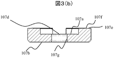
- FIG. 3B is an enlarged cross-sectional view taken along line AA of FIG. 3a. It is an expanded sectional view of the fixed iron core part concerning the embodiment of the present invention.
- FIG. 1 is a cross-sectional view showing the structure of a fuel injection valve according to an embodiment of the present invention.
- 2 to 3 are explanatory views of the mover according to the embodiment of the present invention.
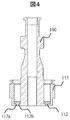
- FIG. 4 is an enlarged cross-sectional view of the fixed iron core according to the embodiment of the present invention.
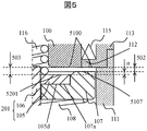
- FIG. 5 is an enlarged view of the movable part according to the embodiment of the present invention.
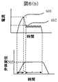
- FIG. 6 is an enlarged view of a movable part and a drive current waveform when performing a small stroke according to the embodiment of the present invention.
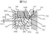
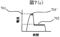
- FIG. 7 is an enlarged view of a movable part and a drive current waveform when a large stroke is performed according to the embodiment of the present invention.
- the fuel injection valve 1 is given a valve opening signal to the coil 115 through an injection hole constituting member 110 having a fuel injection hole 110 ′ for injecting fuel, a nozzle body 111 containing a valve body 106 driven up and down, and a terminal 119.
- the magnetic circuit 120 is composed of an internal fixed iron core 100, a first movable element 107, a second movable element 105, an external fixed iron core 113, and an upper fixed iron core 114. Further, when not energized, it is supported by the upper spring 116 that is supported upward by the spring retaining pin 117 and that generates force downward, which applies force to the valve body 106, and the receiving portion 111 a of the nozzle body 111. It is constituted by a lower spring 108 that applies an upward force via one movable element 107.
- the valve body 106 and the injection hole constituting member 110 pass through the fuel passage portion 109a of the guide member 109 at the tip of the fuel injection valve 1 through the directional fuel passage 106b, 111 ′ between the nozzle body 111 and the valve body 106.
- the fuel is injected from the fuel injection hole 110 ′ through the gap generated in the seat 106c when energized.
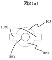
- FIG. 2 (a) is a top view of the second mover 105 as viewed from above the fuel injection valve.
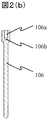
- FIG. 2B is a cross-sectional view of the valve body 106 in FIG. 1 in the orthogonal direction.
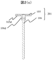
- FIG. 2C is a cross-sectional view of the movable body 201 in which the second movable element 105 and the valve body 106 are combined.
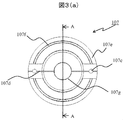
- FIG. 3A is a top view of the first movable element 107 viewed from above the fuel injection valve.
- FIG. 3B is a cross-sectional view taken along the line AA in FIG.
- the second mover 105 is characterized by having a circular portion 105a serving as a magnetic attraction surface and an outer peripheral extension portion 105b extending from the circular portion to the outer periphery.
- an inner diameter hole 105c is formed to be integrated with the outer diameter portion of the valve body 106 by press fitting or the like, and operates as an integrated movable body 201.
- the first mover 107 has an upper surface 107e that is paired with an inner peripheral side and an outer peripheral side fixed iron core, and a protrusion 107f is formed on a part thereof.
- the protrusion 107f suppresses the sticking force caused by the fuel existing between the fixed iron core and the upper surface 107e of the first mover.
- the first movable element 107 has an inner surface 107 a that comes into contact with the lower surface 105 d of the second movable element in the movable body 201.
- a hole 107g is opened at the center of the first movable element 107, and an outer peripheral portion 106d of the valve body 106 in the movable body 201 passes therethrough.
- the fuel injection valve of the present invention is characterized in that a spacer 112 is provided between the inner fixed iron core 100 and the outer fixed iron core 113.
- the spacer 112 may be joined to the inner fixed iron core 100 and the outer fixed iron core 113 by welding, or may be joined by tight bonding of metals at the crushed portions 112a and 112b due to a load from above.
- the inner fixed iron core 100 and the outer fixed iron core 113 are magnetic materials, while the spacer 112 is a nonmagnetic material. If the spacer 112 is made of a magnetic material, the magnetic circuit 120 configured in FIG. 1 includes the inner fixed iron core 100, the spacer 112, the outer fixed iron core 113, and the upper fixed iron core 114, and the first movable element 107. As a result, the magnetic attraction force is not generated in the second mover 105.
- This operation is characterized in that a large and small lift is configured using a difference in magnetic attraction force generated in the first movable element 107 and the second movable element 105 generated by a current flowing in the coil.
- FIG. 5 is a diagram of the valve closing state of the movable part according to the embodiment of the present invention.
- FIG. 6A is an enlarged view of the movable portion at the time of a small stroke according to the embodiment of the present invention
- FIG. 6B is a drive current waveform and a displacement diagram of the valve body when the small stroke is generated.
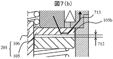
- FIGS. 7A and 7B are enlarged views of the movable portion at the time of a large stroke according to the embodiment of the present invention
- FIG. 7C is a drive current waveform when the large stroke is generated.
- 7 is set to be larger than the peak value 601 in FIG. 6B
- the holding current value 702 is set to be larger than the holding current value 602 in FIG. 6B.
- the same reference numerals as those in FIG. 1 are the same as the parts in FIG. 1, and detailed description will be omitted and will be referred to in this operation description as necessary.
- a gap 502 is formed between the lower end surface 5100 of the inner fixed iron core 100 and the outer fixed iron core 113 and the upper end surface 5107 of the first mover 107.
- a gap 503 is formed between the upper end surfaces 5201 of the movable elements 105.
- the gaps 502 and 503 are the lift amount of the fuel injection valve.
- the gap 503 is larger than the gap 502, and constitutes two lifts in the fuel injection valve in the present invention.
- the difference ⁇ between the two lift amounts is constituted by the difference in height between the upper end surfaces 5107 and 5201.
- Fa2 and Ff + Fs ⁇ Fa1 and Ff + Fs> Fa2 the valve body 106 has a small stroke.
- the second movable element 105 does not contact the inner fixed core 100 and the lower end surface 5100 of the outer fixed core 113, and the first movable element middle surface 107a and the lower surface 105d of the second movable element contact each other. It has become a state. And the magnetic flux which generate
- the displacement of the valve body 106 will be described with reference to FIG.
- the valve body 106 rises rapidly in the section a. Then, the drive current is lowered from the peak value, the ascending speed of the valve body 106 is slowed in the b section, and the holding current 602 is applied to the coil so that the valve body 106 is held in the open state as in the c section.
- the configuration when achieving a large lift amount of the two lift amounts will be described below with reference to FIGS.
- the first movable element 107 is attracted upward, and at the same time, the second movable element 105 is also attracted to the internal fixed iron core 100 and the externally fixed core.
- the lower end surface 5100 of the iron core 113, the upper end surface 5107 of the first mover, and the upper end surface 5201 of the second mover are in contact with each other to form a large stroke.
- magnetic flux generated by energization of the coil 115 passes, and main magnetic circuits 710 and 711 are configured.
- a current value 701 ′ holding the peak current is generated, and then a holding current value 702 is generated.
- a magnetic attraction force is generated so as to exceed the force applied downward by the difference between the upper spring 116 and the lower spring 108 applied to the second mover and the force received downward by the fuel. It is driven together with the mover 107. In other words, it is as follows.
- differential force between the upper spring 116 and the lower spring 108 Fs.
- the second mover 105 has the outer peripheral extension portion 105 b extending from the circular portion to the outer periphery, and is extended to the outer peripheral side for the following reason. .
- a gap 712 is formed between the first movable element 107 and the second movable element 105 during a large lift.
- the fuel injection valve has the cross section of FIG. 7A over the entire circumference, the magnetic flux that has entered the second armature 105 from the internal fixed iron core 100 is less likely to pass through the external fixed iron core 113. It is difficult to obtain the magnetic attractive force required for the second mover 105.
- the second movable element 105 is extended to the outer peripheral side so as to have the outer peripheral extension 105b extending from the circular portion to the outer periphery, a part in the circumferential direction is shown in FIG.
- the cross section has a simple cross section, the magnetic flux that has entered the second movable element 105 from the internal fixed iron core 100 passes to the external fixed iron core 113, and the magnetic attractive force required for the second movable element 105 is obtained.
- the design that takes into consideration the reduction of the total weight of the movable body 201 is achieved by the valve seat portion of the valve body that is generated when the fuel injection valve is closed. It is desirable from the viewpoint of suppressing the bounce.
- either the large lift amount or the small lift amount is determined first, and then the difference between the heights of the first movable element 107 and the second movable element 105 is determined.
- the other lift amount is to be determined. More preferably, after the small lift amount is determined first, the large lift amount is determined. The reason is that the smaller the lift amount, the larger the proportion of the variation in the injection amount of the fuel injection valve corresponding to the lift adjustment error.
- the two lifts are switched when mounted on an internal combustion engine (not shown)
- the scenes that require a small injection amount by reducing the lift amount are mainly when the rotational speed of the internal combustion engine is low, when the generated torque of the internal combustion engine is low, and when the fuel injection pressure is low.
- a certain threshold value is crossed based on the information of the air flow sensor that senses the intake air amount, the crank sensor that senses the rotation speed, and the pressure sensor that senses the fuel injection pressure, Switch to the waveform of.
- the accelerator opening is suddenly reduced in an operating state where the accelerator opening is large, the rotation speed is high, and the torque is high, it is desirable to switch to a waveform that makes a small stroke even if the fuel pressure is high.
- the intake air amount, the internal combustion engine speed, the fuel injection pressure, and the accelerator opening are sensed, and the current waveform to be supplied to the fuel injection valve is switched according to the threshold value, but other information is used. However, if the same effect can be obtained, switching can be performed.
- the second movable element 105 and the valve body 106 are originally separate members and are integrated by press-fitting or the like. However, even if the structure is originally integrated, the internally fixed core 100 As long as it is sucked into the external fixed iron core 113 and the fuel can be sealed in the valve seat portion 106c, the configuration is not questioned.
- the waveform is described as a waveform that does not hold the peak current during a small stroke and a waveform that holds a peak current during a large stroke. Even if it is the current waveform of this, the effect which concerns on this invention is not impaired.
- the spacer 112 which is a non-magnetic member, is configured as a single component, but even if it is configured by a plurality of members, the operational effects according to the present invention are not impaired.
Landscapes
- Engineering & Computer Science (AREA)
- Chemical & Material Sciences (AREA)
- Combustion & Propulsion (AREA)
- Mechanical Engineering (AREA)
- General Engineering & Computer Science (AREA)
- Physics & Mathematics (AREA)
- Electromagnetism (AREA)
- Fuel-Injection Apparatus (AREA)
Abstract
Description
本発明の第1の実施形態に係る燃料噴射弁について、図1~図7を参照しながら以下に説明する。図1は本発明の実施形態に係る燃料噴射弁の構造を示す断面図である。図2乃至3は本発明の実施形態に係る可動子の説明図である。図4は本発明の実施形態に係る固定鉄心部の拡大断面図である。図5は本発明の実施形態に係る可動部の拡大図である。図6は本発明の実施形態に係る、小ストロークをするときの可動部の拡大図及び駆動電流波形である。図7は本発明の実施形態に係る、大ストロークをするときの可動部の拡大図及び駆動電流波形である。
100・・・内部固定鉄心
105・・・第二の可動子
106・・・弁体
107・・・第一の可動子
108・・・下部バネ
110・・・噴射孔構成部材
111・・・ノズル体
112・・・スペーサ
113・・・外部固定鉄心
116・・・上部バネ
Claims (5)
- 摺動可能に設けられた弁体と、前記弁体と協働する可動子と、前記可動子と対向する位置に設けられた固定鉄心と、環状の弁座が形成された弁座部材と、前記可動子を変位させ前記弁体を前記弁座に離着座させるコイルと、
を備えてなる燃料噴射弁において、
一つの前記弁体に対して複数の前記可動子が係合していることを特徴とする燃料噴射弁。 - 前記可動子は、第一の可動子と、第二の可動子とから構成され、前記第二の可動子のリフト量が、前記第一の可動子のリフト量より大きいことを特徴とする請求項1記載の燃料噴射弁。
- 前記第二の可動子は、前記第一の可動子より前記弁体側に配置され、前記第二の可動子の一部が前記第一の可動子内へ突出していることを特徴とする請求項1乃至2に記載の燃料噴射弁。
- 前記二つの可動子と対応する、固定鉄心の面が径方向に対して内周側と外周側に分けられていることを特徴とする請求項1乃至3に記載の燃料噴射弁。
- 前記二つの可動子がリフトする際に燃料噴射弁に投入する、駆動電流波形が、リフト量に応じて異なることを特徴とする請求項1乃至4に記載の燃料噴射弁。
Priority Applications (6)
| Application Number | Priority Date | Filing Date | Title |
|---|---|---|---|
| CN201480005608.1A CN104937256B (zh) | 2013-01-24 | 2014-01-10 | 燃料喷射装置 |
| DE112014000539.8T DE112014000539T5 (de) | 2013-01-24 | 2014-01-10 | Kraftstoffeinspritzeinrichtung |
| US14/763,029 US9541046B2 (en) | 2013-01-24 | 2014-01-10 | Fuel injection device |
| US15/364,846 US9726127B2 (en) | 2013-01-24 | 2016-11-30 | Fuel injection device |
| US15/640,838 US10240567B2 (en) | 2013-01-24 | 2017-07-03 | Fuel injection device |
| US16/169,598 US20190063387A1 (en) | 2013-01-24 | 2018-10-24 | Fuel Injection Device |
Applications Claiming Priority (2)
| Application Number | Priority Date | Filing Date | Title |
|---|---|---|---|
| JP2013010731A JP6186126B2 (ja) | 2013-01-24 | 2013-01-24 | 燃料噴射装置 |
| JP2013-010731 | 2013-01-24 |
Related Child Applications (2)
| Application Number | Title | Priority Date | Filing Date |
|---|---|---|---|
| US14/763,029 A-371-Of-International US9541046B2 (en) | 2013-01-24 | 2014-01-10 | Fuel injection device |
| US15/364,846 Continuation US9726127B2 (en) | 2013-01-24 | 2016-11-30 | Fuel injection device |
Publications (1)
| Publication Number | Publication Date |
|---|---|
| WO2014115587A1 true WO2014115587A1 (ja) | 2014-07-31 |
Family
ID=51227379
Family Applications (1)
| Application Number | Title | Priority Date | Filing Date |
|---|---|---|---|
| PCT/JP2014/050272 Ceased WO2014115587A1 (ja) | 2013-01-24 | 2014-01-10 | 燃料噴射装置 |
Country Status (5)
| Country | Link |
|---|---|
| US (4) | US9541046B2 (ja) |
| JP (1) | JP6186126B2 (ja) |
| CN (2) | CN108005824B (ja) |
| DE (1) | DE112014000539T5 (ja) |
| WO (1) | WO2014115587A1 (ja) |
Cited By (1)
| Publication number | Priority date | Publication date | Assignee | Title |
|---|---|---|---|---|
| US9670251B2 (en) | 2014-07-21 | 2017-06-06 | The Arizona Board Of Regents On Behalf Of The University Of Arizona | ANG-(1-7) derivative oligopeptides and methods for using and producing the same |
Families Citing this family (14)
| Publication number | Priority date | Publication date | Assignee | Title |
|---|---|---|---|---|
| JP6186126B2 (ja) * | 2013-01-24 | 2017-08-23 | 日立オートモティブシステムズ株式会社 | 燃料噴射装置 |
| JP6277941B2 (ja) * | 2014-11-05 | 2018-02-14 | 株式会社デンソー | 燃料噴射装置 |
| EP3362669B1 (en) * | 2015-10-12 | 2019-09-18 | Continental Automotive GmbH | Electromagnetic injection valve and method for assembling an electromagnetic injection valve |
| JP6613973B2 (ja) | 2016-03-10 | 2019-12-04 | 株式会社デンソー | 燃料噴射装置 |
| WO2018021123A1 (ja) * | 2016-07-28 | 2018-02-01 | 株式会社デンソー | 燃料噴射弁 |
| JP6520983B2 (ja) * | 2016-07-28 | 2019-05-29 | 株式会社デンソー | 燃料噴射弁、および燃料噴射弁の製造方法 |
| US10883434B2 (en) | 2016-08-26 | 2021-01-05 | Hitachi Automotive Systems, Ltd. | Control device for fuel injection device |
| US20190249631A1 (en) * | 2016-08-26 | 2019-08-15 | Hitachi Automotive Systems, Ltd. | Fuel Injection Valve |
| WO2018150834A1 (ja) * | 2017-02-17 | 2018-08-23 | 日立オートモティブシステムズ株式会社 | 燃料噴射制御装置及び燃料噴射制御方法 |
| DE112018001413B4 (de) * | 2017-04-14 | 2025-08-07 | Hitachi Astemo, Ltd. | Steuervorrichtung für Kraftstoffeinspritzventil |
| JP2020204268A (ja) * | 2017-08-25 | 2020-12-24 | 日立オートモティブシステムズ株式会社 | 燃料噴射制御装置及び燃料噴射制御方法 |
| US11242830B2 (en) | 2017-10-13 | 2022-02-08 | Hitachi Astemo, Ltd. | Fuel injection valve |
| WO2019163383A1 (ja) | 2018-02-23 | 2019-08-29 | 日立オートモティブシステムズ株式会社 | 燃料噴射弁及びその組立方法 |
| JP7070069B2 (ja) * | 2018-05-14 | 2022-05-18 | 株式会社デンソー | 電磁弁およびこれを用いた燃料噴射装置 |
Citations (7)
| Publication number | Priority date | Publication date | Assignee | Title |
|---|---|---|---|---|
| JP2003511604A (ja) * | 1999-10-07 | 2003-03-25 | ローベルト ボツシユ ゲゼルシヤフト ミツト ベシユレンクテル ハフツング | 燃料噴射弁 |
| JP2003269289A (ja) * | 2002-03-14 | 2003-09-25 | Hitachi Ltd | 電磁式燃料噴射弁およびその駆動方法 |
| JP2005307751A (ja) * | 2004-04-16 | 2005-11-04 | Denso Corp | 燃料噴射弁 |
| JP2010053812A (ja) * | 2008-08-29 | 2010-03-11 | Nippon Soken Inc | 電磁アクチュエータ |
| JP2011208603A (ja) * | 2010-03-30 | 2011-10-20 | Denso Corp | 燃料噴射弁 |
| JP2013167194A (ja) * | 2012-02-15 | 2013-08-29 | Toyota Motor Corp | 燃料噴射弁 |
| JP2013227880A (ja) * | 2012-04-24 | 2013-11-07 | Nippon Soken Inc | 燃料噴射弁 |
Family Cites Families (46)
| Publication number | Priority date | Publication date | Assignee | Title |
|---|---|---|---|---|
| JP2757220B2 (ja) * | 1989-11-30 | 1998-05-25 | アイシン精機株式会社 | 燃料噴射装置 |
| DE4324781B4 (de) * | 1993-07-23 | 2005-03-24 | Robert Bosch Gmbh | Elektromagnetventil |
| US5463996A (en) * | 1994-07-29 | 1995-11-07 | Caterpillar Inc. | Hydraulically-actuated fluid injector having pre-injection pressurizable fluid storage chamber and direct-operated check |
| US5544816A (en) * | 1994-08-18 | 1996-08-13 | Siemens Automotive L.P. | Housing for coil of solenoid-operated fuel injector |
| US5709342A (en) * | 1995-11-09 | 1998-01-20 | Caterpillar Inc. | Vented armature/valve assembly and fuel injector utilizing same |
| JPH1144275A (ja) * | 1997-07-03 | 1999-02-16 | Zexel Corp | 燃料噴射装置用ソレノイドバルブ |
| US6047907A (en) * | 1997-12-23 | 2000-04-11 | Siemens Automotive Corporation | Ball valve fuel injector |
| JP2000046224A (ja) * | 1998-07-28 | 2000-02-18 | Zexel Corp | ディスク型電磁弁の製造方法 |
| DE19931822A1 (de) * | 1999-07-08 | 2001-01-11 | Bosch Gmbh Robert | Brennstoffeinspritzventil |
| US6405947B2 (en) * | 1999-08-10 | 2002-06-18 | Siemens Automotive Corporation | Gaseous fuel injector having low restriction seat for valve needle |
| DE19953788A1 (de) * | 1999-11-09 | 2001-05-10 | Bosch Gmbh Robert | Elektromagnetischer Aktuator |
| JP2001208233A (ja) * | 2000-01-31 | 2001-08-03 | Aisin Seiki Co Ltd | 電磁弁 |
| DE10004960A1 (de) * | 2000-02-04 | 2001-08-09 | Bosch Gmbh Robert | Brennstoffeinspritzventil und Verfahren zu dessen Betätigung |
| US6279843B1 (en) * | 2000-03-21 | 2001-08-28 | Caterpillar Inc. | Single pole solenoid assembly and fuel injector using same |
| US6676044B2 (en) * | 2000-04-07 | 2004-01-13 | Siemens Automotive Corporation | Modular fuel injector and method of assembling the modular fuel injector |
| US6390067B1 (en) * | 2000-08-10 | 2002-05-21 | Delphi Technologies, Inc. | Valve seat retainer for a fuel injector |
| US20020134958A1 (en) * | 2000-10-16 | 2002-09-26 | Luciano Migliori | Solenoid microvalve |
| JP3734702B2 (ja) * | 2000-10-17 | 2006-01-11 | 株式会社日立製作所 | 電磁式燃料噴射弁 |
| US6520421B2 (en) * | 2000-12-29 | 2003-02-18 | Siemens Automotive Corporation | Modular fuel injector having an integral filter and o-ring retainer |
| US6648247B2 (en) * | 2001-02-02 | 2003-11-18 | Siemens Automotive Corporation | Combined filter and adjuster for a fuel injector |
| US7093362B2 (en) * | 2001-03-30 | 2006-08-22 | Siemens Vdo Automotive Corporation | Method of connecting components of a modular fuel injector |
| US6595189B2 (en) * | 2001-08-10 | 2003-07-22 | Caterpillar Inc | Method of reducing noise in a mechanically actuated fuel injection system and engine using same |
| DE60210306T2 (de) * | 2001-09-06 | 2006-11-30 | Invensys Sensor Systems | Druckregelventil mit einstellmerkmalen |
| JP4055571B2 (ja) * | 2001-12-26 | 2008-03-05 | トヨタ自動車株式会社 | 電磁式燃料噴射弁 |
| US20030178509A1 (en) * | 2002-03-19 | 2003-09-25 | Visteon Global Technologies, Inc. | Fuel injector with flux washer |
| JP3874698B2 (ja) * | 2002-06-05 | 2007-01-31 | 株式会社デンソー | 電磁弁用ソレノイド |
| DE10226649A1 (de) * | 2002-06-14 | 2004-01-08 | Siemens Ag | Dosiervorrichtung für Fluide, insbesondere Kraftfahrzeug-Einspritzventil |
| US20040036048A1 (en) * | 2002-08-20 | 2004-02-26 | Petersen Peter Waygaard | Gaseous fuel injector |
| JP2004225659A (ja) | 2003-01-27 | 2004-08-12 | Toyota Motor Corp | インジェクタの駆動制御装置 |
| DE60307117T2 (de) * | 2003-12-22 | 2006-12-21 | Siemens Vdo Automotive S.P.A., Fauglia | Ventilkörper für einen Flüssigkeitsinjektor |
| US7407119B2 (en) * | 2004-05-19 | 2008-08-05 | Continental Automotive Systems Us, Inc. | Magnetic circuit using negative magnetic susceptibility |
| EP1670005B1 (en) * | 2004-12-13 | 2008-12-03 | Delphi Technologies, Inc. | Actuator arrangement and fuel injector incorporating an actuator arrangement |
| US7819379B2 (en) * | 2005-02-08 | 2010-10-26 | Robert Bosch Gmbh | Attachment of an armature to a valve needle in a fuel injector control valve |
| DE102005053115A1 (de) * | 2005-11-08 | 2007-05-10 | Robert Bosch Gmbh | Optimierte Ankergruppenführung für Magnetventile |
| JP2008045519A (ja) * | 2006-08-21 | 2008-02-28 | Toyota Motor Corp | 内燃機関の燃料噴射弁及び燃料噴射弁の制御装置 |
| US7926745B2 (en) * | 2006-11-27 | 2011-04-19 | Mitsubishi Electric Corporation | Fuel injection valve |
| JP4637931B2 (ja) * | 2008-05-22 | 2011-02-23 | 三菱電機株式会社 | 燃料噴射弁 |
| DE102008032133B4 (de) * | 2008-07-08 | 2015-08-20 | Continental Automotive Gmbh | Kraftstoffeinspritzvorrichtung |
| US7866301B2 (en) * | 2009-01-26 | 2011-01-11 | Caterpillar Inc. | Self-guided armature in single pole solenoid actuator assembly and fuel injector using same |
| JP2010209719A (ja) * | 2009-03-09 | 2010-09-24 | Hitachi Automotive Systems Ltd | 燃料噴射装置 |
| US7942349B1 (en) * | 2009-03-24 | 2011-05-17 | Meyer Andrew E | Fuel injector |
| DE102010002845A1 (de) * | 2010-03-15 | 2011-09-15 | Robert Bosch Gmbh | Kraftstoff-Injektor |
| JP2011208530A (ja) * | 2010-03-29 | 2011-10-20 | Keihin Corp | 電磁式燃料噴射弁及びその製造方法 |
| JP5768536B2 (ja) * | 2010-10-05 | 2015-08-26 | 株式会社デンソー | 燃料噴射弁 |
| EP2535552B1 (en) * | 2011-06-15 | 2015-02-25 | Continental Automotive GmbH | Valve assembly for an injection valve and injection valve |
| JP6186126B2 (ja) * | 2013-01-24 | 2017-08-23 | 日立オートモティブシステムズ株式会社 | 燃料噴射装置 |
-
2013
- 2013-01-24 JP JP2013010731A patent/JP6186126B2/ja not_active Expired - Fee Related
-
2014
- 2014-01-10 CN CN201711251832.0A patent/CN108005824B/zh not_active Expired - Fee Related
- 2014-01-10 DE DE112014000539.8T patent/DE112014000539T5/de active Pending
- 2014-01-10 WO PCT/JP2014/050272 patent/WO2014115587A1/ja not_active Ceased
- 2014-01-10 US US14/763,029 patent/US9541046B2/en not_active Expired - Fee Related
- 2014-01-10 CN CN201480005608.1A patent/CN104937256B/zh not_active Expired - Fee Related
-
2016
- 2016-11-30 US US15/364,846 patent/US9726127B2/en not_active Expired - Fee Related
-
2017
- 2017-07-03 US US15/640,838 patent/US10240567B2/en active Active
-
2018
- 2018-10-24 US US16/169,598 patent/US20190063387A1/en not_active Abandoned
Patent Citations (7)
| Publication number | Priority date | Publication date | Assignee | Title |
|---|---|---|---|---|
| JP2003511604A (ja) * | 1999-10-07 | 2003-03-25 | ローベルト ボツシユ ゲゼルシヤフト ミツト ベシユレンクテル ハフツング | 燃料噴射弁 |
| JP2003269289A (ja) * | 2002-03-14 | 2003-09-25 | Hitachi Ltd | 電磁式燃料噴射弁およびその駆動方法 |
| JP2005307751A (ja) * | 2004-04-16 | 2005-11-04 | Denso Corp | 燃料噴射弁 |
| JP2010053812A (ja) * | 2008-08-29 | 2010-03-11 | Nippon Soken Inc | 電磁アクチュエータ |
| JP2011208603A (ja) * | 2010-03-30 | 2011-10-20 | Denso Corp | 燃料噴射弁 |
| JP2013167194A (ja) * | 2012-02-15 | 2013-08-29 | Toyota Motor Corp | 燃料噴射弁 |
| JP2013227880A (ja) * | 2012-04-24 | 2013-11-07 | Nippon Soken Inc | 燃料噴射弁 |
Cited By (1)
| Publication number | Priority date | Publication date | Assignee | Title |
|---|---|---|---|---|
| US9670251B2 (en) | 2014-07-21 | 2017-06-06 | The Arizona Board Of Regents On Behalf Of The University Of Arizona | ANG-(1-7) derivative oligopeptides and methods for using and producing the same |
Also Published As
| Publication number | Publication date |
|---|---|
| US9541046B2 (en) | 2017-01-10 |
| CN104937256A (zh) | 2015-09-23 |
| US9726127B2 (en) | 2017-08-08 |
| CN108005824B (zh) | 2020-10-09 |
| US20190063387A1 (en) | 2019-02-28 |
| US20170298882A1 (en) | 2017-10-19 |
| JP2014141924A (ja) | 2014-08-07 |
| US10240567B2 (en) | 2019-03-26 |
| JP6186126B2 (ja) | 2017-08-23 |
| CN104937256B (zh) | 2018-01-02 |
| CN108005824A (zh) | 2018-05-08 |
| US20150354515A1 (en) | 2015-12-10 |
| US20170082078A1 (en) | 2017-03-23 |
| DE112014000539T5 (de) | 2015-10-22 |
Similar Documents
| Publication | Publication Date | Title |
|---|---|---|
| JP6186126B2 (ja) | 燃料噴射装置 | |
| KR101947298B1 (ko) | 복합 자기회로 이중 영구자석 전자석 및 복합 자기회로 이중 영구자석 고속전자밸브 | |
| US9920726B2 (en) | Fuel injection valve | |
| CN101539084B (zh) | 共轨式电控喷射器 | |
| JP4211814B2 (ja) | 電磁式燃料噴射弁 | |
| JP5537472B2 (ja) | 燃料噴射装置 | |
| KR102274061B1 (ko) | 내연 기관을 위한 연료 분사 밸브 | |
| JP6655723B2 (ja) | 燃料噴射弁 | |
| JP2010216344A (ja) | 燃料噴射弁 | |
| JP5482267B2 (ja) | 燃料噴射弁 | |
| JP2013167194A (ja) | 燃料噴射弁 | |
| JP2017207071A (ja) | 燃料噴射装置 | |
| JP2011144731A (ja) | 燃料噴射弁 | |
| JP6762393B2 (ja) | 燃料噴射装置 | |
| JP2010209719A (ja) | 燃料噴射装置 | |
| JPWO2019163383A1 (ja) | 燃料噴射弁及びその組立方法 | |
| CN107542612A (zh) | 用于喷射阀的阀组件以及喷射阀 | |
| CN107091359B (zh) | 一种直通式混合进气的内导向燃气喷射阀 | |
| JP2015121188A (ja) | 燃料噴射弁 | |
| JP2012197739A (ja) | 燃料噴射弁 | |
| JPH0552445U (ja) | 電磁弁の弁構造 | |
| CN102094736A (zh) | 燃料喷射阀 | |
| JP2017160912A (ja) | 燃料噴射装置 | |
| JP2013057262A (ja) | 燃料噴射弁 | |
| JP2014134207A (ja) | 燃料噴射装置 |
Legal Events
| Date | Code | Title | Description |
|---|---|---|---|
| 121 | Ep: the epo has been informed by wipo that ep was designated in this application |
Ref document number: 14743783 Country of ref document: EP Kind code of ref document: A1 |
|
| WWE | Wipo information: entry into national phase |
Ref document number: 14763029 Country of ref document: US |
|
| NENP | Non-entry into the national phase |
Ref country code: DE |
|
| WWE | Wipo information: entry into national phase |
Ref document number: 112014000539 Country of ref document: DE Ref document number: 1120140005398 Country of ref document: DE |
|
| 122 | Ep: pct application non-entry in european phase |
Ref document number: 14743783 Country of ref document: EP Kind code of ref document: A1 |