WO2014115565A1 - Système optique à grossissement variable, dispositif optique et procédé de fabrication d'un système optique à grossissement variable - Google Patents
Système optique à grossissement variable, dispositif optique et procédé de fabrication d'un système optique à grossissement variable Download PDFInfo
- Publication number
- WO2014115565A1 WO2014115565A1 PCT/JP2014/000396 JP2014000396W WO2014115565A1 WO 2014115565 A1 WO2014115565 A1 WO 2014115565A1 JP 2014000396 W JP2014000396 W JP 2014000396W WO 2014115565 A1 WO2014115565 A1 WO 2014115565A1
- Authority
- WO
- WIPO (PCT)
- Prior art keywords
- lens group
- focal length
- lens
- optical system
- refractive power
- Prior art date
Links
Images


Classifications
-
- G—PHYSICS
- G02—OPTICS
- G02B—OPTICAL ELEMENTS, SYSTEMS OR APPARATUS
- G02B15/00—Optical objectives with means for varying the magnification
- G02B15/14—Optical objectives with means for varying the magnification by axial movement of one or more lenses or groups of lenses relative to the image plane for continuously varying the equivalent focal length of the objective
- G02B15/145—Optical objectives with means for varying the magnification by axial movement of one or more lenses or groups of lenses relative to the image plane for continuously varying the equivalent focal length of the objective having five groups only
- G02B15/1451—Optical objectives with means for varying the magnification by axial movement of one or more lenses or groups of lenses relative to the image plane for continuously varying the equivalent focal length of the objective having five groups only the first group being positive
- G02B15/145121—Optical objectives with means for varying the magnification by axial movement of one or more lenses or groups of lenses relative to the image plane for continuously varying the equivalent focal length of the objective having five groups only the first group being positive arranged +-+-+
-
- G—PHYSICS
- G02—OPTICS
- G02B—OPTICAL ELEMENTS, SYSTEMS OR APPARATUS
- G02B1/00—Optical elements characterised by the material of which they are made; Optical coatings for optical elements
- G02B1/10—Optical coatings produced by application to, or surface treatment of, optical elements
- G02B1/11—Anti-reflection coatings
- G02B1/113—Anti-reflection coatings using inorganic layer materials only
-
- G—PHYSICS
- G02—OPTICS
- G02B—OPTICAL ELEMENTS, SYSTEMS OR APPARATUS
- G02B15/00—Optical objectives with means for varying the magnification
- G02B15/14—Optical objectives with means for varying the magnification by axial movement of one or more lenses or groups of lenses relative to the image plane for continuously varying the equivalent focal length of the objective
- G02B15/146—Optical objectives with means for varying the magnification by axial movement of one or more lenses or groups of lenses relative to the image plane for continuously varying the equivalent focal length of the objective having more than five groups
- G02B15/1461—Optical objectives with means for varying the magnification by axial movement of one or more lenses or groups of lenses relative to the image plane for continuously varying the equivalent focal length of the objective having more than five groups the first group being positive
-
- G—PHYSICS
- G02—OPTICS
- G02B—OPTICAL ELEMENTS, SYSTEMS OR APPARATUS
- G02B15/00—Optical objectives with means for varying the magnification
- G02B15/14—Optical objectives with means for varying the magnification by axial movement of one or more lenses or groups of lenses relative to the image plane for continuously varying the equivalent focal length of the objective
- G02B15/16—Optical objectives with means for varying the magnification by axial movement of one or more lenses or groups of lenses relative to the image plane for continuously varying the equivalent focal length of the objective with interdependent non-linearly related movements between one lens or lens group, and another lens or lens group
- G02B15/163—Optical objectives with means for varying the magnification by axial movement of one or more lenses or groups of lenses relative to the image plane for continuously varying the equivalent focal length of the objective with interdependent non-linearly related movements between one lens or lens group, and another lens or lens group having a first movable lens or lens group and a second movable lens or lens group, both in front of a fixed lens or lens group
- G02B15/167—Optical objectives with means for varying the magnification by axial movement of one or more lenses or groups of lenses relative to the image plane for continuously varying the equivalent focal length of the objective with interdependent non-linearly related movements between one lens or lens group, and another lens or lens group having a first movable lens or lens group and a second movable lens or lens group, both in front of a fixed lens or lens group having an additional fixed front lens or group of lenses
- G02B15/173—Optical objectives with means for varying the magnification by axial movement of one or more lenses or groups of lenses relative to the image plane for continuously varying the equivalent focal length of the objective with interdependent non-linearly related movements between one lens or lens group, and another lens or lens group having a first movable lens or lens group and a second movable lens or lens group, both in front of a fixed lens or lens group having an additional fixed front lens or group of lenses arranged +-+
-
- G—PHYSICS
- G02—OPTICS
- G02B—OPTICAL ELEMENTS, SYSTEMS OR APPARATUS
- G02B15/00—Optical objectives with means for varying the magnification
- G02B15/14—Optical objectives with means for varying the magnification by axial movement of one or more lenses or groups of lenses relative to the image plane for continuously varying the equivalent focal length of the objective
- G02B15/16—Optical objectives with means for varying the magnification by axial movement of one or more lenses or groups of lenses relative to the image plane for continuously varying the equivalent focal length of the objective with interdependent non-linearly related movements between one lens or lens group, and another lens or lens group
- G02B15/20—Optical objectives with means for varying the magnification by axial movement of one or more lenses or groups of lenses relative to the image plane for continuously varying the equivalent focal length of the objective with interdependent non-linearly related movements between one lens or lens group, and another lens or lens group having an additional movable lens or lens group for varying the objective focal length
-
- G—PHYSICS
- G02—OPTICS
- G02B—OPTICAL ELEMENTS, SYSTEMS OR APPARATUS
- G02B27/00—Optical systems or apparatus not provided for by any of the groups G02B1/00 - G02B26/00, G02B30/00
- G02B27/0018—Optical systems or apparatus not provided for by any of the groups G02B1/00 - G02B26/00, G02B30/00 with means for preventing ghost images
-
- G—PHYSICS
- G02—OPTICS
- G02B—OPTICAL ELEMENTS, SYSTEMS OR APPARATUS
- G02B27/00—Optical systems or apparatus not provided for by any of the groups G02B1/00 - G02B26/00, G02B30/00
- G02B27/0025—Optical systems or apparatus not provided for by any of the groups G02B1/00 - G02B26/00, G02B30/00 for optical correction, e.g. distorsion, aberration
-
- G—PHYSICS
- G02—OPTICS
- G02B—OPTICAL ELEMENTS, SYSTEMS OR APPARATUS
- G02B27/00—Optical systems or apparatus not provided for by any of the groups G02B1/00 - G02B26/00, G02B30/00
- G02B27/64—Imaging systems using optical elements for stabilisation of the lateral and angular position of the image
- G02B27/646—Imaging systems using optical elements for stabilisation of the lateral and angular position of the image compensating for small deviations, e.g. due to vibration or shake
Definitions
- the present invention relates to a variable magnification optical system, an optical apparatus, and a method for manufacturing the variable magnification optical system.
- variable power optical system suitable for a photographic camera, an electronic still camera, a video camera, and the like has been proposed (for example, see Patent Document 1).
- variable magnification optical systems suitable for photographic cameras, electronic still cameras, video cameras, etc. the demands for ghosts and flares, which are one of the factors that impair optical performance, have been increasing. Therefore, higher performance is required for the antireflection film applied to the lens surface, and multilayer film design technology and multilayer film formation technology continue to advance to meet the demand (see, for example, Patent Document 2). ).
- the conventional variable power optical system has a problem that the aberration fluctuation during zooming is large.
- the conventional variable power optical system also has a problem that reflected light, which is ghost or flare, which affects the optical performance from the optical surface is likely to be generated.
- the present invention has been made in view of such a problem, and an object thereof is to provide a variable magnification optical system, an optical device, and a method for manufacturing the variable magnification optical system, in which aberration fluctuation at the time of variable magnification is satisfactorily suppressed. .
- the present invention further provides a variable power optical system, an optical device, and a method for manufacturing the variable power optical system having high optical performance capable of reducing ghosts and flares while satisfactorily suppressing aberration fluctuation during zooming.
- the purpose is to do.
- a variable magnification optical system includes, in order from the object side, a first lens group having a positive refractive power, a second lens group having a negative refractive power, and a positive refraction.
- at least part of the second lens group to the fifth lens group is moved so as to include a component orthogonal to the optical axis, and the condition of the following equation is satisfied.
- f1 Focal length of the first lens group
- f2 Focal length of the second lens group
- f3 Focal length of the third lens group
- variable magnification optical system it is preferable that the following condition is satisfied. 0.18 ⁇ f3 / ( ⁇ f4) ⁇ 0.92
- f4 focal length of the fourth lens group
- variable magnification optical system it is preferable that the following condition is satisfied. 0.82 ⁇ ( ⁇ f4) / f5 ⁇ 1.58
- f4 focal length of the fourth lens group
- f5 focal length of the fifth lens group
- an aperture stop is provided on the image side with respect to the second lens group.
- variable magnification optical system preferably, an aperture stop is provided between the third lens group and the fifth lens group.
- an aperture stop is provided between the third lens group and the fourth lens group.
- At the time of focusing at least a part of the third lens group is moved along the optical axis.
- the second lens group is fixed with respect to the image plane during zooming.
- variable magnification optical system it is preferable that at least a part of the second lens group can be moved so as to include a component in a direction orthogonal to the optical axis.
- all lens surfaces are spherical surfaces.
- variable magnification optical system it is preferable that the following condition is satisfied. 0.70 ⁇ f1 / (-f4) ⁇ 2.55
- f4 focal length of the fourth lens group
- variable magnification optical system it is preferable that the following condition is satisfied. 0.11 ⁇ f2 / f4 ⁇ 0.62
- f2 Focal length of the second lens group
- f4 Focal length of the fourth lens group
- variable magnification optical system it is preferable that the following condition is satisfied. 9.6 ⁇ ft / ( ⁇ f2) ⁇ 20.0
- ft focal length of the entire system in the telephoto end state
- variable magnification optical system it is preferable that the following condition is satisfied. 3.9 ⁇ ft / ( ⁇ f4) ⁇ 8.8
- ft focal length of the entire system in the telephoto end state
- f4 focal length of the fourth lens group
- variable magnification optical system it is preferable that the following condition is satisfied. 0.8 ⁇ ( ⁇ f4) / f5 ⁇ 1.8
- f4 focal length of the fourth lens group
- f5 focal length of the fifth lens group
- variable magnification optical system it is preferable that the following condition is satisfied. 0.3 ⁇ ( ⁇ f2) / f5 ⁇ 0.8
- f5 focal length of the fifth lens group
- variable magnification optical system it is preferable that the following condition is satisfied. 1.3 ⁇ f1 / ( ⁇ f4) ⁇ 3.0
- f4 focal length of the fourth lens group
- variable magnification optical system it is preferable that the following condition is satisfied. 1.9 ⁇ f1 / f5 ⁇ 3.2
- f5 focal length of the fifth lens group
- variable magnification optical system it is preferable that the following condition is satisfied. 0.32 ⁇ ( ⁇ f4) / f5 ⁇ 1.93
- f4 focal length of the fourth lens group
- f5 focal length of the fifth lens group
- variable magnification optical system it is preferable that the following condition is satisfied. 0.74 ⁇ f1 / ( ⁇ f4) ⁇ 2.82
- f4 focal length of the fourth lens group
- variable magnification optical system it is preferable that the following condition is satisfied. 0.44 ⁇ ( ⁇ f2) / f3 ⁇ 0.86
- variable magnification optical system it is preferable that the following condition is satisfied. 0.32 ⁇ ( ⁇ f4) / f5 ⁇ 2.07
- f4 focal length of the fourth lens group
- f5 focal length of the fifth lens group
- variable magnification optical system it is preferable that the following condition is satisfied. 0.29 ⁇ f3 / ( ⁇ f4) ⁇ 0.87
- f4 focal length of the fourth lens group
- variable magnification optical system preferably, at least one of the optical surfaces is provided with an antireflection film including at least one layer formed using a wet process.
- the antireflection film is a multilayer film, and the outermost surface layer of the multilayer film is a layer formed using the wet process.
- An optical apparatus includes the above-described variable magnification optical system that forms an image of an object on a predetermined image plane.
- variable magnification optical system includes, in order from the object side, a first lens group having a positive refractive power, a second lens group having a negative refractive power, and a third lens having a positive refractive power.
- at least a part of the fifth lens group can be moved from the second lens group so as to include a component in a direction orthogonal to the optical axis, and the following condition is satisfied.
- f1 focal length of the first lens group
- f2 focal length of the second lens group
- f3 focal length of the third lens group
- f5 focal length of the fifth lens group
- variable magnification optical system it is preferable that the following condition is satisfied. 0.70 ⁇ f1 / (-f4) ⁇ 2.55 Where f4: focal length of the fourth lens group
- variable magnification optical system it is preferable that the following condition is satisfied. 0.11 ⁇ f2 / f4 ⁇ 0.62
- f4 focal length of the fourth lens group
- the optical apparatus includes the variable magnification optical system according to the second aspect of the present invention that forms an image of an object on a predetermined image plane.
- the zoom optical system includes, in order from the object side, a first lens group having a positive refractive power, a second lens group having a negative refractive power, and a third lens having a positive refractive power.
- a lens group, a fourth lens group having a negative refractive power, and a fifth lens group having a positive refractive power, and the second lens group is fixed with respect to the image plane upon zooming, The condition of the following formula is satisfied.
- ft focal length of the entire system in the telephoto end state
- f2 focal length of the second lens group
- f4 focal length of the fourth lens group
- variable magnification optical system it is preferable that the following condition is satisfied. 0.8 ⁇ ( ⁇ f4) / f5 ⁇ 1.8 Where f5: focal length of the fifth lens group
- variable magnification optical system it is preferable that the following condition is satisfied. 0.3 ⁇ ( ⁇ f2) / f5 ⁇ 0.8 Where f5: focal length of the fifth lens group
- the optical apparatus includes the variable magnification optical system according to the third aspect of the present invention that forms an image of an object on a predetermined image plane.
- a zoom optical system includes, in order from the object side, a first lens group having a positive refractive power, a second lens group having a negative refractive power, and a third lens having a positive refractive power.
- a lens group, a fourth lens group having a negative refractive power, and a fifth lens group having a positive refractive power, and the second lens group is fixed with respect to the image plane upon zooming, The condition of the following formula is satisfied.
- f1 focal length of the first lens group
- f2 focal length of the second lens group
- f4 focal length of the fourth lens group
- f5 focal length of the fifth lens group
- variable magnification optical system it is preferable that the following condition is satisfied. 0.8 ⁇ ( ⁇ f4) / f5 ⁇ 1.8
- variable magnification optical system it is preferable that the following condition is satisfied. 0.3 ⁇ ( ⁇ f2) / f5 ⁇ 0.8
- An optical device includes the zoom optical system according to the fourth aspect of the present invention, which forms an image of an object on a predetermined image plane.
- variable power optical system in order from the object side, a first lens group having a positive refractive power, a second lens group having a negative refractive power, and a third lens having a positive refractive power
- a fourth lens group having a negative refractive power and a fifth lens group having a positive refractive power, and the second lens group and the fourth lens group are placed on the image plane upon zooming.
- the condition of the following formula is satisfied.
- f1 focal length of the first lens group
- f2 focal length of the second lens group
- f4 focal length of the fourth lens group
- f5 focal length of the fifth lens group
- variable magnification optical system it is preferable that the following condition is satisfied. 0.74 ⁇ f1 / ( ⁇ f4) ⁇ 2.82
- the optical device includes the zoom optical system according to the fifth aspect of the present invention, which forms an image of an object on a predetermined image plane.
- a zoom optical system includes, in order from the object side, a first lens group having a positive refractive power, a second lens group having a negative refractive power, and a third lens having a positive refractive power. And a fourth lens group having a negative refractive power and a fifth lens group having a positive refractive power, and the second lens group and the fourth lens group are image planes during zooming. And satisfies the following condition.
- f2 focal length of the second lens group
- f3 focal length of the third lens group
- f4 focal length of the fourth lens group
- f5 focal length of the fifth lens group
- variable magnification optical system it is preferable that the following condition is satisfied. 0.29 ⁇ f3 / ( ⁇ f4) ⁇ 0.87
- An optical device includes the zoom optical system according to the sixth aspect of the present invention, which forms an image of an object on a predetermined image plane.
- variable magnification optical system manufacturing method includes, in order from the object side, a first lens group having a positive refractive power, a second lens group having a negative refractive power, and a third lens having a positive refractive power.
- a method of manufacturing a variable magnification optical system having a lens group, a fourth lens group having a negative refractive power, and a fifth lens group having a positive refractive power are arranged so as to move along the optical axis, and arranged so that at least a part of the fifth lens group from the second lens group can move including a component in a direction orthogonal to the optical axis. Arrange so that the conditions of the formula are satisfied.
- f1 focal length of the first lens group
- f2 focal length of the second lens group
- f3 focal length of the third lens group
- variable magnification optical system manufacturing method includes, in order from the object side, a first lens group having a positive refractive power, a second lens group having a negative refractive power, and a positive refractive power. And a fourth lens group having a negative refractive power, and a fifth lens group having a positive refractive power.
- One lens group is arranged so as to move along the optical axis, and at least a part of the fifth lens group from the second lens group is arranged so as to be able to move including a component perpendicular to the optical axis. And so as to satisfy the condition of the following formula.
- f1 focal length of the first lens group
- f2 focal length of the second lens group
- f3 focal length of the third lens group
- f5 focal length of the fifth lens group
- variable magnification optical system manufacturing method includes, in order from the object side, a first lens group having a positive refractive power, a second lens group having a negative refractive power, and a positive refractive power. And a fourth lens group having a negative refractive power, and a fifth lens group having a positive refractive power.
- the two lens groups are arranged so as to be fixed with respect to the image plane, and are arranged so as to satisfy the following condition.
- ft focal length of the entire system in the telephoto end state
- f2 focal length of the second lens group
- f4 focal length of the fourth lens group
- a variable magnification optical system manufacturing method comprising, in order from the object side, a first lens group having a positive refractive power, a second lens group having a negative refractive power, and a positive refractive power. And a fourth lens group having a negative refractive power, and a fifth lens group having a positive refractive power.
- the two lens groups are arranged so as to be fixed with respect to the image plane, and are arranged so as to satisfy the following condition.
- f1 focal length of the first lens group
- f2 focal length of the second lens group
- f4 focal length of the fourth lens group
- f5 focal length of the fifth lens group
- variable magnification optical system manufacturing method includes, in order from the object side, a first lens group having a positive refractive power, a second lens group having a negative refractive power, and a positive refractive power. And a fourth lens group having a negative refractive power, and a fifth lens group having a positive refractive power.
- the second lens group and the fourth lens group are disposed so as to be fixed with respect to the image plane, and are disposed so as to satisfy the following condition.
- f1 focal length of the first lens group
- f2 focal length of the second lens group
- f4 focal length of the fourth lens group
- f5 focal length of the fifth lens group
- the zoom optical system manufacturing method includes, in order from the object side, a first lens group having a positive refractive power, a second lens group having a negative refractive power, and a positive refractive power. And a fourth lens group having a negative refractive power, and a fifth lens group having a positive refractive power.
- the second lens group and the fourth lens group are disposed so as to be fixed with respect to the image plane, and are disposed so as to satisfy the following condition.
- f2 focal length of the second lens group
- f3 focal length of the third lens group
- f4 focal length of the fourth lens group
- f5 focal length of the fifth lens group
- variable magnification optical system an optical apparatus, and a method for manufacturing the variable magnification optical system that can satisfactorily suppress aberration fluctuations during variable magnification.
- variable power optical system an optical device, and a variable power optical system having high optical performance capable of further reducing ghosts and flares while satisfactorily suppressing aberration fluctuations during zooming.
- a method can be provided.
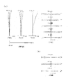
- FIG. 5A is a diagram illustrating various aberrations in the wide-angle end state of the variable magnification optical system according to the first example.
- FIG. 9A is a diagram illustrating various aberrations in the infinite focus state, and FIG. It is a coma aberration figure when correct
- FIG. 5A is a diagram illustrating various aberrations in the intermediate focal length state of the variable magnification optical system according to the first example.
- FIG. 9A is a diagram illustrating various aberrations in the infinite focus state, and FIG. It is a coma aberration figure when blurring correction is performed.
- FIG. 9A is a diagram illustrating various aberrations in the wide-angle end state of the variable magnification optical system according to the first example.
- FIG. 9A is a diagram illustrating various aberrations in the infinite focus state, and FIG. It is a coma aberration figure when blurring correction is performed.
- FIG. 9A is a diagram illustrating various aberrations in the wide-angle
- FIG. 5A is a diagram illustrating various aberrations in the telephoto end state of the variable magnification optical system according to the first example.
- FIG. 9A is a diagram illustrating various aberrations in the infinite focus state, and FIG. It is a coma aberration figure when correct
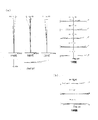
- FIG. 7A is a diagram illustrating various aberrations in the wide-angle end state of the variable magnification optical system according to the second example, where FIG.
- FIG. 9A is a diagram illustrating various aberrations in the infinite focus state, and FIG. It is a coma aberration figure when correct
- FIG. 7A is a diagram illustrating various aberrations in the intermediate focal length state of the variable magnification optical system according to the second example, where FIG. 9A is a diagram illustrating various aberrations in the infinite focus state, and FIG. It is a coma aberration figure when blurring correction is performed.
- FIG. 5A is a diagram illustrating various aberrations in the telephoto end state of the variable magnification optical system according to Example 2, wherein FIG. 9A is a diagram illustrating various aberrations in the infinite focus state, and FIG. It is a coma aberration figure when correct
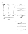
- FIG. 7A is a diagram illustrating various aberrations in the wide-angle end state of the variable magnification optical system according to the third example, where FIG. 9A is a diagram illustrating various aberrations in the infinite focus state, and FIG. It is a coma aberration figure when correct
- FIG. 7A is a diagram illustrating various aberrations in the intermediate focal length state of the variable magnification optical system according to the third example, where FIG. 9A is a diagram illustrating various aberrations in the infinite focus state, and FIG. It is a coma aberration figure when blurring correction is performed.
- FIG. 9A is a diagram illustrating various aberrations in the wide-angle end state of the variable magnification optical system according to the third example, where FIG. 9A is a diagram illustrating various aberrations in the infinite focus state, and FIG. It is a coma aberration figure when blurring correction is performed.
- FIG. 9A is a diagram illustrating various aberrations in the infinite focus state
- FIG. 7A is a diagram illustrating various aberrations in the telephoto end state of the variable magnification optical system according to the third example, where FIG. 9A is a diagram illustrating various aberrations in the infinite focus state, and FIG. It is a coma aberration figure when correct
- FIG. 7A is a diagram illustrating various aberrations in the wide-angle end state of the variable magnification optical system according to the fourth example, where FIG. 9A is a diagram illustrating all aberrations in the infinite focus state, and FIG. It is a coma aberration figure when correct
- FIG. 9A is a diagram illustrating various aberrations in the wide-angle end state of the variable magnification optical system according to the fourth example, where FIG. 9A is a diagram illustrating all aberrations in the infinite focus state, and FIG. It is a coma aberration figure when correct
- FIG. 7A is a diagram illustrating various aberrations in the intermediate focal length state of the variable magnification optical system according to the fourth example, where FIG. 9A is a diagram illustrating various aberrations in the infinite focus state, and FIG. It is a coma aberration figure when blurring correction is performed.
- FIG. 7A is a diagram illustrating various aberrations in the telephoto end state of the variable magnification optical system according to the fourth example, where FIG. 9A is a diagram illustrating various aberrations in the infinite focus state, and FIG. It is a coma aberration figure when correct
- FIG. 7A is a diagram illustrating various aberrations of the variable magnification optical system according to Example 5 in the wide-angle end state, where FIG. 9A is a diagram illustrating aberrations in an infinite focus state, and FIG. It is a coma aberration figure when correct
- FIG. 7A is a diagram illustrating various aberrations in the intermediate focal length state of the variable magnification optical system according to the fifth example, where FIG. 9A is a diagram illustrating various aberrations in the infinite focus state, and FIG. It is a coma aberration figure when blurring correction is performed.
- FIG. 6A is a diagram illustrating various aberrations of the zoom optical system according to Example 5 in the telephoto end state, where FIG.
- FIG. 5A is a diagram illustrating aberrations in the infinite focus state, and FIG. It is a coma aberration figure when correct
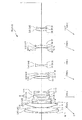
- a sectional view of a camera carrying the above-mentioned variable magnification optical system is shown.
- the variable magnification optical system ZL includes, in order from the object side, a first lens group G1 having a positive refractive power, a second lens group G2 having a negative refractive power, A third lens group G3 having a positive refractive power, a fourth lens group G4 having a negative refractive power, and a fifth lens group G5 having a positive refractive power are configured.
- the zoom optical system ZL it is desirable to move the first lens group G1 with respect to the image plane I along the optical axis during zooming. With this configuration, it is possible to reduce aberration fluctuations during zooming.
- the refractive power of the first lens group G1 can be weakened, it is possible to reduce the deterioration of aberration when decentering due to manufacturing errors occurs.
- This variable magnification optical system ZL may be at least part of the second lens group G2 to the fifth lens group G5 (a plurality of lens groups or any one lens group, It may be desirable to move the lens so as to include a component orthogonal to the optical axis. At this time, it is more desirable to move at least a part of the second lens group G2 so as to include a component orthogonal to the optical axis. With this configuration, camera shake correction can be performed with a lens having a small diameter, so that the size of the lens barrel can be reduced.
- variable magnification optical system ZL satisfies the following conditional expression (1).
- f1 Focal length of the first lens group G1
- f2 Focal length of the second lens group G2
- Conditional expression (1) defines an appropriate focal length of the first lens group G1 with respect to the focal length of the second lens group G2. By satisfying conditional expression (1), it is possible to satisfactorily correct spherical aberration and chromatic aberration in the telephoto end state. If the lower limit of conditional expression (1) is not reached, the refractive power of the first lens group G1 becomes large, and it becomes difficult to correct spherical aberration and chromatic aberration in the telephoto end state, which is not preferable. If the lower limit of conditional expression (1) is 4.45, the effect of the present application can be ensured.
- the refractive power of the first lens group G1 becomes small, which leads to an increase in the total length, which is not preferable. If the upper limit of conditional expression (1) is 5.30, the effect of the present application can be ensured.
- f1 Focal length of the first lens group G1
- f3 Focal length of the third lens group G3
- Conditional expression (2) defines an appropriate focal length of the first lens group G1 with respect to the focal length of the third lens group G3. By satisfying conditional expression (2), it is possible to satisfactorily correct spherical aberration and chromatic aberration in the telephoto end state. If the lower limit of conditional expression (2) is not reached, the refractive power of the first lens group G1 becomes large, and it becomes difficult to correct spherical aberration and chromatic aberration in the telephoto end state. If the lower limit value of conditional expression (2) is 2.20, the effect of the present application can be ensured.
- conditional expression (2) when the value exceeds the upper limit value of the conditional expression (2), the refractive power of the first lens group G1 becomes small, which leads to an increase in the total length, which is not preferable. If the upper limit of conditional expression (2) is 4.35, the effect of the present application can be ensured.
- variable magnification optical system ZL satisfies the following conditional expression (3).
- Conditional expression (3) defines an appropriate focal length of the third lens group G3 with respect to the focal length of the fourth lens group G4. By satisfying conditional expression (3), it is possible to satisfactorily correct spherical aberration and chromatic aberration in the telephoto end state. If the lower limit of conditional expression (3) is not reached, the refractive power of the third lens group G3 becomes large, and it becomes difficult to correct spherical aberration and chromatic aberration in the telephoto end state. If the lower limit value of conditional expression (3) is 0.22, the effect of the present application can be ensured.
- conditional expression (3) when the value exceeds the upper limit value of the conditional expression (3), the refractive power of the third lens group G3 becomes small, which leads to an increase in the total length, which is not preferable. If the upper limit value of conditional expression (3) is 0.85, the effect of the present application can be ensured.
- Conditional expression (4) defines an appropriate focal length of the fourth lens group G4 with respect to the focal length of the fifth lens group G5. By satisfying conditional expression (4), it is possible to satisfactorily correct curvature of field and distortion in the wide-angle end state. If the lower limit of conditional expression (4) is not reached, the refractive power of the fourth lens group G4 becomes large, and it becomes difficult to correct chromatic aberration in the telephoto end state. If the lower limit of conditional expression (4) is 0.88, the effect of the present application can be ensured. On the other hand, exceeding the upper limit value of conditional expression (4) is not preferable because the refractive power of the fifth lens group G5 becomes large and it becomes difficult to correct curvature of field and distortion in the wide-angle end state. If the upper limit of conditional expression (4) is 1.52, the effect of the present application can be ensured.
- the zoom optical system ZL preferably has an aperture stop S on the image side with respect to the second lens group G2. At this time, it is desirable to have an aperture stop S between the third lens group G3 and the fifth lens group G5. Furthermore, it is desirable to have an aperture stop S between the third lens group G3 and the fourth lens group G4. With this configuration, coma and curvature of field can be favorably corrected.
- This zoom optical system ZL desirably moves at least a part of the third lens group G3 along the optical axis during focusing.
- the zoom optical system ZL it is desirable that the second lens group G2 is fixed with respect to the image plane I during zooming.
- the configuration of the lens barrel in zooming can be simplified, and the size of the lens barrel can be reduced.
- this zoom optical system ZL it is preferable that all lens surfaces are spherical surfaces. This configuration is preferable because it facilitates lens processing and assembly adjustment, and prevents deterioration in optical performance due to errors in processing and assembly adjustment. Further, even when the image plane is deviated, it is preferable because there is little deterioration in drawing performance.
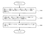
- the lenses are arranged to prepare the lens groups G1 to G5, respectively (step S100).
- the first lens group G1 is arranged to move along the optical axis (step S200).
- at least a part of the second lens group G2 to the fifth lens group G5 is arranged so as to move including a component orthogonal to the optical axis (step S300).
- the lens groups G1 to G5 are arranged so as to satisfy the conditional expressions (1) and (2) described above (step S400).
- a cemented lens in which a negative meniscus lens L11 having a convex surface facing the object side and a biconvex lens L12 are cemented, and a positive lens having a convex surface facing the object side.
- a biconcave lens L25 is arranged to form the second lens group G2, and a biconvex lens L31 and a cemented lens in which a negative meniscus lens L32 having a convex surface facing the object side and a biconvex lens L33 are arranged are arranged to form a third lens.
- a cemented lens obtained by cementing a plano-concave lens L56 having a concave surface directed toward the object side and a negative meniscus lens L57 having a concave surface directed toward the object side are disposed to form a fifth lens group G5.
- the lens groups thus prepared are arranged in the above-described procedure to manufacture the variable magnification optical system ZL.
- the variable magnification optical system ZL also has a first lens group G1 having a positive refractive power and a second lens group having a negative refractive power in order from the object side. G2, a third lens group G3 having a positive refractive power, a fourth lens group G4 having a negative refractive power, and a fifth lens group G5 having a positive refractive power. .
- the zoom optical system ZL desirably moves the first lens group G1 relative to the image plane I along the optical axis during zooming. With this configuration, it is possible to reduce aberration fluctuations during zooming. Since the refractive power of the first lens group G1 can be weakened, it is possible to reduce the deterioration of aberration when decentering due to a manufacturing error occurs.
- This variable magnification optical system ZL may be at least part of the second lens group G2 to the fifth lens group G5 (a plurality of lens groups or any one lens group, It may be desirable to move the lens so as to include a component orthogonal to the optical axis. At this time, it is more desirable to move at least a part of the second lens group G2 so as to include a component orthogonal to the optical axis. With this configuration, camera shake correction can be performed with a lens having a small diameter, so that the size of the lens barrel can be reduced.
- variable magnification optical system ZL satisfies the following conditional expression (5).
- f1 Focal length of the first lens group G1
- f2 Focal length of the second lens group G2
- Conditional expression (5) defines an appropriate focal length of the first lens group G1 with respect to the focal length of the second lens group G2. By satisfying conditional expression (5), it is possible to satisfactorily correct spherical aberration and chromatic aberration in the telephoto end state. If the lower limit of conditional expression (5) is not reached, the refractive power of the first lens group G1 becomes large, and it becomes difficult to correct spherical aberration and chromatic aberration in the telephoto end state. If the lower limit of conditional expression (5) is 4.45, the effect of the present application can be ensured.
- conditional expression (5) when the value exceeds the upper limit value of the conditional expression (5), the refractive power of the first lens group G1 becomes small, which leads to an increase in the total length. If the upper limit value of conditional expression (5) is 5.30, the effect of the present application can be ensured.
- Conditional expression (6) defines an appropriate focal length of the third lens group G3 with respect to the focal length of the fifth lens group G5. By satisfying conditional expression (6), it is possible to satisfactorily correct spherical aberration and chromatic aberration in the telephoto end state. If the lower limit of conditional expression (6) is not reached, the refractive power of the third lens group G3 becomes large, and it becomes difficult to correct spherical aberration and chromatic aberration at the telephoto end, which is not preferable. If the lower limit value of conditional expression (6) is 0.24, the effect of the present application can be ensured.
- conditional expression (6) when the value exceeds the upper limit value of the conditional expression (6), the refractive power of the third lens group G3 is reduced, which leads to an increase in the total length, which is not preferable. If the upper limit value of conditional expression (6) is 1.00, the effect of the present application can be ensured.
- variable magnification optical system ZL satisfies the following conditional expression (7).
- f1 Focal length of the first lens group G1
- f4 Focal length of the fourth lens group G4
- Conditional expression (7) defines an appropriate focal length of the first lens group G1 with respect to the focal length of the fourth lens group G4. By satisfying conditional expression (7), it is possible to satisfactorily correct spherical aberration and chromatic aberration in the telephoto end state. If the lower limit of conditional expression (7) is not reached, the refractive power of the first lens group G1 becomes large, and it becomes difficult to correct spherical aberration and chromatic aberration in the telephoto end state. If the lower limit value of conditional expression (7) is 0.77, the effect of the present application can be ensured.
- conditional expression (7) when the value exceeds the upper limit value of the conditional expression (7), the refractive power of the first lens group G1 becomes small, which leads to an increase in the total length, which is not preferable. If the upper limit of conditional expression (7) is 2.45, the effect of the present application can be ensured.
- f2 Focal length of the second lens group G2
- f4 Focal length of the fourth lens group G4
- Conditional expression (8) defines an appropriate focal length of the second lens group G2 with respect to the focal length of the fourth lens group G4.
- conditional expression (8) if the upper limit value of conditional expression (8) is exceeded, the refractive power of the fourth lens group G4 increases, and it becomes difficult to correct chromatic aberration at the telephoto end. If the upper limit of conditional expression (8) is 0.55, the effect of the present application can be ensured.
- the zoom optical system ZL preferably has an aperture stop S on the image side with respect to the second lens group G2. At this time, it is desirable to have an aperture stop S between the third lens group G3 and the fifth lens group G5. Furthermore, it is desirable to have an aperture stop S between the third lens group G3 and the fourth lens group G4. With this configuration, coma and curvature of field can be favorably corrected.
- This zoom optical system ZL desirably moves at least a part of the third lens group G3 along the optical axis during focusing.
- the zoom optical system ZL it is desirable that the second lens group G2 is fixed with respect to the image plane I during zooming.
- the configuration of the lens barrel in zooming can be simplified, and the size of the lens barrel can be reduced.
- this zoom optical system ZL it is preferable that all lens surfaces are spherical surfaces. This configuration is preferable because it facilitates lens processing and assembly adjustment, and prevents deterioration in optical performance due to errors in processing and assembly adjustment. Further, even when the image plane is deviated, it is preferable because there is little deterioration in drawing performance.
- the lenses are arranged to prepare the lens groups G1 to G5, respectively (step S100).
- the first lens group G1 is arranged to move along the optical axis (step S200).
- at least a part of the second lens group G2 to the fifth lens group G5 is arranged so as to move including a component orthogonal to the optical axis (step S300).
- the lens groups G1 to G5 are arranged so as to satisfy the conditional expressions (5) and (6) described above (step S400).
- a cemented lens in which a negative meniscus lens L11 having a convex surface facing the object side and a biconvex lens L12 are cemented, and a positive lens having a convex surface facing the object side.
- a biconcave lens L25 is arranged to form the second lens group G2, and a biconvex lens L31 and a cemented lens in which a negative meniscus lens L32 having a convex surface facing the object side and a biconvex lens L33 are arranged are arranged to form a third lens.
- a cemented lens obtained by cementing a plano-concave lens L56 having a concave surface directed toward the object side and a negative meniscus lens L57 having a concave surface directed toward the object side are disposed to form a fifth lens group G5.
- the lens groups thus prepared are arranged in the above-described procedure to manufacture the variable magnification optical system ZL.
- the variable magnification optical system ZL also has a first lens group G1 having a positive refractive power and a second lens group having a negative refractive power in order from the object side. G2, a third lens group G3 having a positive refractive power, a fourth lens group G4 having a negative refractive power, and a fifth lens group G5 having a positive refractive power. .
- the zoom optical system ZL it is desirable that the second lens group G2 is fixed with respect to the image plane during zooming. With this configuration, the amount of movement of each lens group during zooming can be reduced. By fixing the second lens group G2, it is possible to reduce the influence of eccentricity due to manufacturing errors.
- variable magnification optical system ZL satisfies the following conditional expression (9).
- Conditional expression (9) defines an appropriate focal length of the second lens group G2 with respect to the focal length of the entire variable magnification optical system ZL in the telephoto end state.
- conditional expression (9) By satisfying conditional expression (9), coma aberration in the wide-angle end state can be corrected well. If the lower limit of conditional expression (9) is not reached, the refractive power of the second lens group G2 becomes large, and it becomes difficult to correct coma in the wide-angle end state, which is not preferable. If the lower limit value of conditional expression (9) is 10.0, the effect of the present application can be ensured.
- This zoom optical system ZL preferably satisfies the following conditional expression (10).
- Conditional expression (10) defines an appropriate focal length of the fourth lens group G4 with respect to the focal length of the entire variable magnification optical system ZL in the telephoto end state.
- conditional expression (10) it is possible to satisfactorily correct spherical aberration and chromatic aberration in the telephoto end state. If the lower limit of conditional expression (10) is not reached, the refractive power of the fourth lens group G4 becomes large, and correction of chromatic aberration at the telephoto end becomes difficult, which is not preferable. If the lower limit value of conditional expression (10) is 4.0, the effect of the present application can be ensured.
- conditional expression (10) is 8.0, the effect of the present application can be ensured.
- Conditional expression (11) defines an appropriate focal length of the fourth lens group G4 with respect to the focal length of the fifth lens group G5. By satisfying conditional expression (11), it is possible to satisfactorily correct curvature of field and distortion in the wide-angle end state. If the lower limit of conditional expression (11) is not reached, the refractive power of the fourth lens group G4 becomes large, and it becomes difficult to correct chromatic aberration in the telephoto end state, which is not preferable. If the lower limit of conditional expression (11) is 0.9, the effect of the present application can be ensured.
- conditional expression (11) is 1.6, the effect of the present application can be ensured.
- Conditional expression (12) defines an appropriate focal length of the second lens group G2 with respect to the focal length of the fifth lens group G5. By satisfying conditional expression (12), it is possible to satisfactorily correct curvature of field and distortion in the wide-angle end state. If the lower limit of conditional expression (12) is not reached, the refractive power of the second lens group G2 becomes large, and it is difficult to correct coma in the wide-angle end state, which is not preferable. If the lower limit of conditional expression (12) is 0.4, the effect of the present application can be ensured.
- conditional expression (12) On the contrary, if the upper limit value of conditional expression (12) is exceeded, the refractive power of the fifth lens group G5 becomes large, and it becomes difficult to correct curvature of field and distortion in the wide-angle end state, which is not preferable. If the upper limit of conditional expression (12) is 0.7, the effect of the present application can be ensured. If the upper limit of conditional expression (12) is 0.6, the effect of the present application can be further ensured.
- the zoom optical system ZL preferably has an aperture stop S on the image side with respect to the second lens group G2. At this time, it is desirable to have an aperture stop S between the third lens group G3 and the fifth lens group G5. Furthermore, it is desirable to have an aperture stop S between the third lens group G3 and the fourth lens group G4. With this configuration, coma and curvature of field can be favorably corrected.
- This zoom optical system ZL desirably moves at least a part of the third lens group G3 along the optical axis during focusing.
- This variable magnification optical system ZL may be at least part of the second lens group G2 to the fifth lens group G5 (a plurality of lens groups or any one lens group, It may be desirable to move the lens so as to include a component orthogonal to the optical axis. At this time, it is desirable to move at least a part of the second lens group G2 so as to include a component orthogonal to the optical axis. With this configuration, camera shake correction can be performed with a lens having a small diameter, so that the size of the lens barrel can be reduced.
- this zoom optical system ZL it is preferable that all lens surfaces are spherical surfaces. This configuration is preferable because it facilitates lens processing and assembly adjustment, and prevents deterioration in optical performance due to errors in processing and assembly adjustment. Further, even when the image plane is deviated, it is preferable because there is little deterioration in drawing performance.
- the lenses are arranged to prepare the lens groups G1 to G5, respectively (step S100).
- the second lens group G2 is arranged so as to be fixed with respect to the image plane I (step S200).
- the lens groups G1 to G5 are arranged so as to satisfy the conditional expressions (9) and (10) described above (step S300).
- a cemented lens in which a negative meniscus lens L11 having a convex surface facing the object side and a biconvex lens L12 are cemented, and on the object side.
- a positive meniscus lens L13 having a convex surface is disposed to form a first lens group G1, a cemented lens in which a biconvex lens L21 and a biconcave lens L22 are cemented, a biconcave lens L23, and a positive meniscus lens L24 having a convex surface facing the object side.
- a cemented lens and a biconcave lens L25 are arranged to form the second lens group G2, and a biconvex lens L31 and a cemented lens in which a negative meniscus lens L32 having a convex surface facing the object side and a biconvex lens L33 are arranged.
- the third lens group G3 is a cemented lens in which a biconcave lens L41 and a positive meniscus lens L42 having a convex surface facing the object side are cemented.
- a fourth lens group G4 a cemented lens in which a biconvex lens L51, a plano-convex lens L52 having a convex surface facing the object side, a plano-concave lens L53 having a concave surface facing the image side, and a plano-convex lens L54 having a convex surface facing the object side are cemented
- the lens groups thus prepared are arranged in the above-described procedure to manufacture the variable magnification optical system ZL.
- the variable magnification optical system ZL also has a first lens group G1 having a positive refractive power and a second lens group having a negative refractive power in order from the object side. G2, a third lens group G3 having a positive refractive power, a fourth lens group G4 having a negative refractive power, and a fifth lens group G5 having a positive refractive power. .
- the zoom optical system ZL it is desirable that the second lens group G2 is fixed with respect to the image plane during zooming. With this configuration, the amount of movement of each lens group during zooming can be reduced. By fixing the second lens group G2, it is possible to reduce the influence of eccentricity due to manufacturing errors.
- This zoom optical system ZL preferably satisfies the following conditional expression (13).
- f1 Focal length of the first lens group G1
- f2 Focal length of the second lens group G2
- Conditional expression (13) defines an appropriate focal length of the first lens group G1 with respect to the focal length of the second lens group G2. By satisfying conditional expression (13), it is possible to satisfactorily correct spherical aberration and chromatic aberration in the telephoto end state. If the lower limit of conditional expression (13) is not reached, the refractive power of the first lens group G1 becomes large, and it becomes difficult to correct spherical aberration and chromatic aberration in the telephoto end state. If the lower limit value of conditional expression (13) is 3.0, the effect of the present application can be ensured.
- conditional expression (13) when the value exceeds the upper limit value of the conditional expression (13), the refractive power of the first lens group G1 becomes small, which leads to an increase in the total length, which is not preferable. If the upper limit of conditional expression (13) is 6.0, the effect of the present application can be ensured.
- f1 Focal length of the first lens group G1
- f4 Focal length of the fourth lens group G4
- Conditional expression (14) defines an appropriate focal length of the first lens group G1 with respect to the focal length of the fourth lens group G4. By satisfying conditional expression (14), it is possible to satisfactorily correct spherical aberration and chromatic aberration in the telephoto end state. If the lower limit of conditional expression (14) is not reached, the refractive power of the first lens group G1 becomes large, and it becomes difficult to correct spherical aberration and chromatic aberration in the telephoto end state. If the lower limit of conditional expression (14) is 1.4, the effect of the present application can be ensured.
- conditional expression (14) when the value exceeds the upper limit value of the conditional expression (14), the refractive power of the first lens group G1 becomes small, which leads to an increase in the total length, which is not preferable. If the upper limit of conditional expression (14) is 2.8, the effect of the present application can be ensured.
- f1 Focal length of the first lens group G1
- f5 Focal length of the fifth lens group G5
- Conditional expression (15) defines an appropriate focal length of the first lens group G1 with respect to the focal length of the fifth lens group G5. By satisfying conditional expression (15), it is possible to satisfactorily correct spherical aberration and chromatic aberration in the telephoto end state. If the lower limit of conditional expression (15) is not reached, the refractive power of the first lens group G1 becomes large, and it becomes difficult to correct spherical aberration and chromatic aberration in the telephoto end state. If the lower limit of conditional expression (15) is 2.0, the effect of the present application can be ensured.
- conditional expression (15) the refractive power of the fifth lens group G5 increases, and it becomes difficult to correct curvature of field and distortion at the wide angle end, which is not preferable. If the upper limit of conditional expression (15) is 3.0, the effect of the present application can be ensured.
- Conditional expression (16) defines an appropriate focal length of the fourth lens group G4 with respect to the focal length of the fifth lens group G5. By satisfying conditional expression (16), it is possible to satisfactorily correct curvature of field and distortion in the wide-angle end state. If the lower limit of conditional expression (16) is not reached, the refractive power of the fourth lens group G4 becomes large, and it becomes difficult to correct chromatic aberration in the telephoto end state, which is not preferable. If the lower limit of conditional expression (16) is 0.9, the effect of the present application can be ensured.
- conditional expression (16) exceeds the upper limit value of conditional expression (16) is not preferable because the refractive power of the fifth lens group G5 increases and it becomes difficult to correct curvature of field and distortion in the wide-angle end state. If the upper limit of conditional expression (16) is 1.6, the effect of the present application can be ensured.
- variable magnification optical system ZL satisfies the following conditional expression (17).
- Conditional expression (17) defines an appropriate focal length of the second lens group G2 with respect to the focal length of the fifth lens group G5. By satisfying conditional expression (17), it is possible to satisfactorily correct curvature of field and distortion in the wide-angle end state. If the lower limit of conditional expression (17) is not reached, the refractive power of the second lens group G2 becomes large, and it becomes difficult to correct coma in the wide-angle end state, which is not preferable. If the lower limit value of conditional expression (17) is 0.4, the effect of the present application can be ensured.
- conditional expression (17) if the upper limit value of conditional expression (17) is exceeded, the refractive power of the fifth lens group G5 becomes large, and it becomes difficult to correct field curvature and distortion in the wide-angle end state, which is not preferable. If the upper limit value of conditional expression (17) is 0.7, the effect of the present application can be ensured. If the upper limit of conditional expression (17) is 0.6, the effect of the present application can be further ensured.
- the zoom optical system ZL preferably has an aperture stop S on the image side with respect to the second lens group G2. At this time, it is desirable to have an aperture stop S between the third lens group G3 and the fifth lens group G5. Furthermore, it is desirable to have an aperture stop S between the third lens group G3 and the fourth lens group G4. With this configuration, coma and curvature of field can be favorably corrected.
- This zoom optical system ZL desirably moves at least a part of the third lens group G3 along the optical axis during focusing.
- This variable magnification optical system ZL may be at least part of the second lens group G2 to the fifth lens group G5 (a plurality of lens groups or any one lens group, It may be desirable to move the lens so as to include a component orthogonal to the optical axis. At this time, it is more desirable to move at least a part of the second lens group G2 so as to include a component orthogonal to the optical axis. With this configuration, camera shake correction can be performed with a lens having a small diameter, so that the size of the lens barrel can be reduced.
- this zoom optical system ZL it is preferable that all lens surfaces are spherical surfaces. This configuration is preferable because it facilitates lens processing and assembly adjustment, and prevents deterioration in optical performance due to errors in processing and assembly adjustment. Further, even when the image plane is deviated, it is preferable because there is little deterioration in drawing performance.
- the lenses are arranged to prepare the lens groups G1 to G5, respectively (step S100).
- the second lens group G2 is arranged so as to be fixed with respect to the image plane I (step S200).
- the lens groups G1 to G5 are arranged so as to satisfy the conditional expressions (13) and (14) (step S300).
- a cemented lens in which a negative meniscus lens L11 having a convex surface facing the object side and a biconvex lens L12 are cemented, and on the object side.
- a positive meniscus lens L13 having a convex surface is disposed to form a first lens group G1, a cemented lens in which a biconvex lens L21 and a biconcave lens L22 are cemented, a biconcave lens L23, and a positive meniscus lens L24 having a convex surface facing the object side.
- a cemented lens and a biconcave lens L25 are arranged to form the second lens group G2, and a biconvex lens L31 and a cemented lens in which a negative meniscus lens L32 having a convex surface facing the object side and a biconvex lens L33 are arranged.
- the third lens group G3 is a cemented lens in which a biconcave lens L41 and a positive meniscus lens L42 having a convex surface facing the object side are cemented.
- a fourth lens group G4 a cemented lens in which a biconvex lens L51, a plano-convex lens L52 having a convex surface facing the object side, a plano-concave lens L53 having a concave surface facing the image side, and a plano-convex lens L54 having a convex surface facing the object side are cemented
- the lens groups thus prepared are arranged in the above-described procedure to manufacture the variable magnification optical system ZL.
- the variable magnification optical system ZL also has a first lens group G1 having a positive refractive power and a second lens group having a negative refractive power in order from the object side. G2, a third lens group G3 having a positive refractive power, a fourth lens group G4 having a negative refractive power, and a fifth lens group G5 having a positive refractive power. .
- the zoom optical system ZL it is desirable that the second lens group G2 and the fourth lens group G4 are fixed with respect to the image plane during zooming. With this configuration, the configuration of the lens barrel in zooming can be simplified, and the size of the lens barrel can be reduced. In addition, it is possible to suppress degradation of optical performance due to manufacturing errors.
- variable magnification optical system ZL satisfies the following conditional expression (18).
- f1 Focal length of the first lens group G1
- f2 Focal length of the second lens group G2
- Conditional expression (18) defines an appropriate focal length of the first lens group G1 with respect to the focal length of the second lens group G2. By satisfying conditional expression (18), it is possible to satisfactorily correct spherical aberration and chromatic aberration at the telephoto end. If the lower limit of conditional expression (18) is not reached, the refractive power of the first lens group G1 becomes large, and it becomes difficult to correct spherical aberration and chromatic aberration in the telephoto end state, which is not preferable. When the lower limit value of conditional expression (18) is 2.25, the effect of the present application can be ensured.
- this zoom optical system ZL satisfies the following conditional expression (19).
- Conditional expression (19) defines an appropriate focal length of the fourth lens group G4 with respect to the focal length of the fifth lens group G5. By satisfying conditional expression (19), it is possible to satisfactorily correct field curvature and distortion in the wide-angle end state. If the lower limit of conditional expression (19) is not reached, the refractive power of the fourth lens group G4 becomes large and it becomes difficult to correct chromatic aberration at the telephoto end, which is not preferable. If the lower limit of conditional expression (19) is 0.44, the effect of the present application can be ensured.
- conditional expression (19) If the value exceeds the upper limit value of the conditional expression (19), the refractive power of the fifth lens group G5 is increased, which makes it difficult to correct curvature of field and distortion in the wide-angle end state. If the upper limit of conditional expression (19) is 1.63, the effect of the present application can be ensured.
- this zoom optical system ZL satisfies the following conditional expression (20).
- Conditional expression (20) defines an appropriate focal length of the first lens group G1 with respect to the focal length of the fourth lens group G4. By satisfying conditional expression (20), it is possible to satisfactorily correct spherical aberration and chromatic aberration in the telephoto end state. If the lower limit of conditional expression (20) is not reached, the refractive power of the first lens group G1 becomes large, and it becomes difficult to correct spherical aberration and chromatic aberration in the telephoto end state, which is not preferable. If the lower limit of conditional expression (20) is 0.79, the effect of the present application can be ensured.
- the refractive power of the first lens group G1 becomes small, which leads to an increase in the total length, which is not preferable. If the upper limit of conditional expression (20) is 2.71, the effect of the present application can be ensured.
- the zoom optical system ZL preferably has an aperture stop S on the image side with respect to the second lens group G2. At this time, it is desirable to have an aperture stop S between the third lens group G3 and the fifth lens group G5. Furthermore, it is desirable to have an aperture stop S between the third lens group G3 and the fourth lens group G4. With this configuration, coma and curvature of field can be favorably corrected.
- This zoom optical system ZL desirably moves at least a part of the third lens group G3 along the optical axis during focusing.
- This variable magnification optical system ZL may be at least part of the second lens group G2 to the fifth lens group G5 (a plurality of lens groups or any one lens group, It may be desirable to move the lens so as to include a component orthogonal to the optical axis. At this time, it is more desirable to move at least a part of the second lens group G2 so as to include a component orthogonal to the optical axis. With this configuration, camera shake correction can be performed with a lens having a small diameter, so that the size of the lens barrel can be reduced.
- this zoom optical system ZL it is preferable that all lens surfaces are spherical surfaces. This configuration is preferable because it facilitates lens processing and assembly adjustment, and prevents deterioration in optical performance due to errors in processing and assembly adjustment. Further, even when the image plane is deviated, it is preferable because there is little deterioration in drawing performance.
- the lenses are arranged to prepare the lens groups G1 to G5, respectively (step S100).
- the second lens group G2 and the fourth lens group G4 are arranged so as to be fixed with respect to the image plane I (step S200).
- the lens groups G1 to G5 are arranged so as to satisfy the conditional expressions (18) and (19) (step S300).
- a cemented lens in which a negative meniscus lens L11 having a convex surface facing the object side and a biconvex lens L12 are cemented, and on the object side.
- a positive meniscus lens L13 having a convex surface is disposed to form a first lens group G1, a cemented lens in which a biconvex lens L21 and a biconcave lens L22 are cemented, a biconcave lens L23, and a positive meniscus lens L24 having a convex surface facing the object side.
- a cemented lens and a biconcave lens L25 are arranged to form the second lens group G2, and a biconvex lens L31 and a cemented lens in which a negative meniscus lens L32 having a convex surface facing the object side and a biconvex lens L33 are arranged.
- the third lens group G3 is a cemented lens in which a biconcave lens L41 and a positive meniscus lens L42 having a convex surface facing the object side are cemented.
- a fourth lens group G4 a cemented lens in which a biconvex lens L51, a plano-convex lens L52 having a convex surface facing the object side, a plano-concave lens L53 having a concave surface facing the image side, and a plano-convex lens L54 having a convex surface facing the object side are cemented
- the lens groups thus prepared are arranged in the above-described procedure to manufacture the variable magnification optical system ZL.
- the variable magnification optical system ZL also has a first lens group G1 having a positive refractive power and a second lens group having a negative refractive power in order from the object side. G2, a third lens group G3 having a positive refractive power, a fourth lens group G4 having a negative refractive power, and a fifth lens group G5 having a positive refractive power. .
- the zoom optical system ZL it is desirable that the second lens group G2 and the fourth lens group G4 are fixed with respect to the image plane during zooming. With this configuration, the configuration of the lens barrel in zooming can be simplified, and the size of the lens barrel can be reduced. In addition, it is possible to suppress degradation of optical performance due to manufacturing errors.
- variable magnification optical system ZL satisfies the following conditional expression (21).
- Conditional expression (21) defines an appropriate focal length of the second lens group G2 with respect to the focal length of the third lens group G3. By satisfying conditional expression (21), coma aberration at the wide-angle end state, spherical aberration and chromatic aberration at the telephoto end can be corrected well. If the lower limit of conditional expression (21) is not reached, the refractive power of the second lens group G2 becomes large, and it is difficult to correct coma in the wide-angle end state, which is not preferable. If the lower limit value of conditional expression (21) is 0.47, the effect of the present application can be ensured.
- conditional expression (21) if the upper limit value of conditional expression (21) is exceeded, the refractive power of the third lens group G3 becomes large, and it becomes difficult to correct spherical aberration and chromatic aberration in the telephoto end state, which is not preferable.
- the upper limit value of conditional expression (21) is 0.76, the effect of the present application can be ensured.
- variable magnification optical system ZL satisfies the following conditional expression (22).
- Conditional expression (22) defines an appropriate focal length of the fourth lens group G4 with respect to the focal length of the fifth lens group G5. By satisfying conditional expression (22), it is possible to satisfactorily correct curvature of field and distortion in the wide-angle end state. If the lower limit of conditional expression (22) is not reached, the refractive power of the fourth lens group G4 becomes large, and it becomes difficult to correct chromatic aberration at the telephoto end, which is not preferable. If the lower limit value of conditional expression (22) is 0.44, the effect of the present application can be ensured.
- conditional expression (22) exceeds the upper limit value of conditional expression (22) because the refractive power of the fifth lens group G5 increases and it becomes difficult to correct curvature of field and distortion in the wide-angle end state. If the upper limit of conditional expression (22) is 1.63, the effect of the present application can be ensured.
- this zoom optical system ZL satisfies the following conditional expression (23).
- Conditional expression (23) defines an appropriate focal length of the third lens group G3 with respect to the focal length of the fourth lens group G4. By satisfying conditional expression (23), it is possible to satisfactorily correct spherical aberration and chromatic aberration in the telephoto end state. If the lower limit of conditional expression (23) is not reached, the refractive power of the third lens group G3 becomes large, and it becomes difficult to correct spherical aberration and chromatic aberration in the telephoto end state. If the lower limit value of conditional expression (23) is 0.31, the effect of the present application can be ensured.
- the zoom optical system ZL preferably has an aperture stop S on the image side with respect to the second lens group G2. At this time, it is desirable to have an aperture stop S between the third lens group G3 and the fifth lens group G5. Furthermore, it is desirable to have an aperture stop S between the third lens group G3 and the fourth lens group G4. With this configuration, coma and curvature of field can be favorably corrected.
- This zoom optical system ZL desirably moves at least a part of the third lens group G3 along the optical axis during focusing.
- This variable magnification optical system ZL may be at least part of the second lens group G2 to the fifth lens group G5 (a plurality of lens groups or any one lens group, It may be desirable to move the lens so as to include a component orthogonal to the optical axis. At this time, it is more desirable to move at least a part of the second lens group G2 so as to include a component orthogonal to the optical axis. With this configuration, camera shake correction can be performed with a lens having a small diameter, so that the size of the lens barrel can be reduced.
- this zoom optical system ZL it is preferable that all lens surfaces are spherical surfaces. This configuration is preferable because it facilitates lens processing and assembly adjustment, and prevents deterioration in optical performance due to errors in processing and assembly adjustment. Further, even when the image plane is deviated, it is preferable because there is little deterioration in drawing performance.
- the lenses are arranged to prepare the lens groups G1 to G5, respectively (step S100).
- the second lens group G2 and the fourth lens group G4 are arranged so as to be fixed with respect to the image plane I (step S200).
- the lens groups G1 to G5 are arranged so as to satisfy the conditional expressions (21) and (22) described above (step S300).
- a cemented lens in which a negative meniscus lens L11 having a convex surface facing the object side and a biconvex lens L12 are cemented, and on the object side.
- a positive meniscus lens L13 having a convex surface is disposed to form a first lens group G1, a cemented lens in which a biconvex lens L21 and a biconcave lens L22 are cemented, a biconcave lens L23, and a positive meniscus lens L24 having a convex surface facing the object side.
- a cemented lens and a biconcave lens L25 are arranged to form the second lens group G2, and a biconvex lens L31 and a cemented lens in which a negative meniscus lens L32 having a convex surface facing the object side and a biconvex lens L33 are arranged.
- the third lens group G3 is a cemented lens in which a biconcave lens L41 and a positive meniscus lens L42 having a convex surface facing the object side are cemented.
- a fourth lens group G4 a cemented lens in which a biconvex lens L51, a plano-convex lens L52 having a convex surface facing the object side, a plano-concave lens L53 having a concave surface facing the image side, and a plano-convex lens L54 having a convex surface facing the object side are cemented
- the lens groups thus prepared are arranged in the above-described procedure to manufacture the variable magnification optical system ZL.
- the variable magnification optical system ZL also has a first lens group G1 having a positive refractive power and a second lens group having a negative refractive power in order from the object side. G2, a third lens group G3 having a positive refractive power, a fourth lens group G4 having a negative refractive power, and a fifth lens group G5 having a positive refractive power. .
- the zoom optical system ZL it is desirable to move the first lens group G1 with respect to the image plane I along the optical axis during zooming. With this configuration, it is possible to reduce aberration fluctuations during zooming.
- the refractive power of the first lens group G1 can be weakened, it is possible to reduce the deterioration of aberration when decentering due to manufacturing errors occurs.
- This variable magnification optical system ZL may be at least part of the second lens group G2 to the fifth lens group G5 (a plurality of lens groups or any one lens group, It may be desirable to move the lens so as to include a component orthogonal to the optical axis. At this time, it is more desirable to move at least a part of the second lens group G2 so as to include a component orthogonal to the optical axis. With this configuration, camera shake correction can be performed with a lens having a small diameter, so that the size of the lens barrel can be reduced.
- variable magnification optical system ZL satisfies the following conditional expression (24).
- Conditional expression (24) defines an appropriate focal length of the first lens group G1 with respect to the focal length of the second lens group G2. By satisfying conditional expression (24), it is possible to satisfactorily correct spherical aberration and chromatic aberration in the telephoto end state. If the lower limit of conditional expression (24) is not reached, the refractive power of the first lens group G1 becomes large, and it becomes difficult to correct spherical aberration and chromatic aberration in the telephoto end state. If the lower limit value of conditional expression (24) is 4.45, the effect of the present application can be ensured.
- conditional expression (24) if the upper limit value of conditional expression (24) is exceeded, the refractive power of the first lens group G1 will decrease, leading to an increase in the overall length, which is not preferable. If the upper limit value of conditional expression (24) is 5.30, the effect of the present application can be ensured.
- variable magnification optical system ZL satisfies the following conditional expression (25).
- Conditional expression (25) defines an appropriate focal length of the first lens group G1 with respect to the focal length of the third lens group G3. By satisfying conditional expression (25), it is possible to satisfactorily correct spherical aberration and chromatic aberration in the telephoto end state. If the lower limit of conditional expression (25) is not reached, the refractive power of the first lens group G1 becomes large, and it becomes difficult to correct spherical aberration and chromatic aberration in the telephoto end state. If the lower limit value of conditional expression (25) is 2.20, the effect of the present application can be ensured.
- conditional expression (25) if the upper limit value of conditional expression (25) is exceeded, the refractive power of the first lens group G1 becomes small, leading to an increase in the total length, which is not preferable. If the upper limit of conditional expression (25) is 4.35, the effect of the present application can be ensured.
- This zoom optical system ZL preferably satisfies the following conditional expression (26).
- Conditional expression (26) defines an appropriate focal length of the third lens group G3 with respect to the focal length of the fourth lens group G4. By satisfying conditional expression (26), spherical aberration and chromatic aberration in the telephoto end state can be corrected well. If the lower limit of conditional expression (26) is not reached, the refractive power of the third lens group G3 becomes large, and it becomes difficult to correct spherical aberration and chromatic aberration in the telephoto end state. If the lower limit value of conditional expression (26) is 0.22, the effect of the present application can be ensured.
- conditional expression (26) if the upper limit value of conditional expression (26) is exceeded, the refractive power of the third lens group G3 will decrease, leading to an increase in the overall length, which is not preferable. If the upper limit value of conditional expression (26) is 0.85, the effect of the present application can be ensured.
- variable magnification optical system ZL satisfies the following conditional expression (27).
- Conditional expression (27) defines an appropriate focal length of the fourth lens group G4 with respect to the focal length of the fifth lens group G5. By satisfying conditional expression (27), it is possible to satisfactorily correct field curvature and distortion in the wide-angle end state. If the lower limit of conditional expression (27) is not reached, the refractive power of the fourth lens group G4 becomes large, and it becomes difficult to correct chromatic aberration in the telephoto end state, which is not preferable. If the lower limit value of conditional expression (27) is 0.88, the effect of the present application can be ensured.
- conditional expression (27) exceeds the upper limit value of conditional expression (27) because the refractive power of the fifth lens group G5 increases and it becomes difficult to correct curvature of field and distortion in the wide-angle end state. If the upper limit of conditional expression (27) is 1.52, the effect of the present application can be ensured.
- the zoom optical system ZL preferably has an aperture stop S on the image side with respect to the second lens group G2. At this time, it is desirable to have an aperture stop S between the third lens group G3 and the fifth lens group G5. Furthermore, it is desirable to have an aperture stop S between the third lens group G3 and the fourth lens group G4. With this configuration, coma and curvature of field can be favorably corrected.
- This zoom optical system ZL desirably moves at least a part of the third lens group G3 along the optical axis during focusing.
- the zoom optical system ZL it is desirable that the second lens group G2 is fixed with respect to the image plane I during zooming.
- the configuration of the lens barrel in zooming can be simplified, and the size of the lens barrel can be reduced.
- this zoom optical system ZL it is preferable that all lens surfaces are spherical surfaces. This configuration is preferable because it facilitates lens processing and assembly adjustment, and prevents deterioration in optical performance due to errors in processing and assembly adjustment. Further, even when the image plane is deviated, it is preferable because there is little deterioration in drawing performance.
- the variable magnification optical system ZL includes at least one layer formed by a wet process on at least one of the optical surfaces in the nth lens group Gn (the fifth lens group G5 in the present embodiment).
- a protective film is applied.
- the antireflection film applied to the variable magnification optical system ZL is a multilayer film, and the outermost surface layer of the multilayer film is preferably a layer formed using a wet process.
- variable magnification optical system ZL it is preferable to satisfy the following conditional expression (28), where nd is the refractive index of the layer formed by the wet process at the d-line (wavelength 587.6 nm).
- conditional expression 28
- nd is the refractive index of the layer formed by the wet process at the d-line (wavelength 587.6 nm).
- the antireflection film is not limited to a wet process, and may include at least one layer having a refractive index of 1.30 or less (by a dry process or the like). Even if comprised in this way, the effect similar to the case where a wet process is used can be acquired.
- the layer having a refractive index of 1.30 or less is preferably the outermost surface layer among the layers constituting the multilayer film.
- the light beam BM from the object side is incident on the variable magnification optical system ZL1
- the light is an object side lens surface (first ghost generation surface in the biconvex lens L55, and is assigned surface number 29.
- the reflected light is reflected again by the image-side lens surface of the plano-convex lens L54 (second ghost generation surface, corresponding to surface number 28) and reaches the image surface I, and the ghost is reflected. Will be generated.
- the antireflection film will be described in detail later, the antireflection film according to each example has a multilayer structure including seven layers, and the seventh layer of the outermost surface layer is formed by using a wet process and is refracted with respect to the d line. The rate is 1.26 (see Table 16 below).
- the lenses are arranged to prepare the lens groups G1 to G5, respectively (step S100).
- the first lens group G1 is arranged to move along the optical axis (step S200).
- at least a part of the second lens group G2 to the fifth lens group G5 is arranged so as to move including a component orthogonal to the optical axis (step S300).
- the lens groups G1 to G5 are arranged so as to satisfy the conditional expressions (24) and (25) described above (step S400).
- a cemented lens in which a negative meniscus lens L11 having a convex surface facing the object side and a biconvex lens L12 are cemented, and on the object side.
- a positive meniscus lens L13 having a convex surface is disposed to form a first lens group G1, a cemented lens in which a biconvex lens L21 and a biconcave lens L22 are cemented, a biconcave lens L23, and a positive meniscus lens L24 having a convex surface facing the object side.
- a cemented lens and a biconcave lens L25 are arranged to form the second lens group G2, and a biconvex lens L31 and a cemented lens in which a negative meniscus lens L32 having a convex surface facing the object side and a biconvex lens L33 are arranged.
- the third lens group G3 is a cemented lens in which a biconcave lens L41 and a positive meniscus lens L42 having a convex surface facing the object side are cemented.
- a fourth lens group G4 a cemented lens in which a biconvex lens L51, a plano-convex lens L52 having a convex surface facing the object side, a plano-concave lens L53 having a concave surface facing the image side, and a plano-convex lens L54 having a convex surface facing the object side are cemented
- the lens groups thus prepared are arranged in the above-described procedure to manufacture the variable magnification optical system ZL.
- This camera 1 is a so-called mirrorless camera of interchangeable lens provided with a variable magnification optical system ZL according to the present embodiment as a photographing lens 2.
- OLPF Optical Low Pass Filter
- a subject image is formed on the screen.
- the subject image is photoelectrically converted by the photoelectric conversion element provided in the imaging unit 3 to generate an image of the subject.
- EVF Electronic view finder
- variable power optical system ZL is applied to a single-lens reflex camera that has a quick return mirror in the camera body and observes a subject with a finder optical system. Even when the camera is mounted, the same effect as the camera 1 can be obtained.
- variable magnification optical system ZL having the 5-group and 6-group configurations is shown, but the above-described configuration conditions and the like can be applied to other group configurations such as the 7-group. Further, a configuration in which a lens or a lens group is added to the most object side, or a configuration in which a lens or a lens group is added to the most image side may be used.
- the lens group refers to a portion having at least one lens separated by an air interval that changes during zooming.
- a focusing lens group that performs focusing from an object at infinity to a short distance object by moving a single lens group, a plurality of lens groups, or a partial lens group in the optical axis direction may be used.
- the focusing lens group can be applied to autofocus, and is also suitable for driving a motor for autofocus (such as an ultrasonic motor).
- a motor for autofocus such as an ultrasonic motor
- the lens group or the partial lens group is moved so as to have a component in the direction perpendicular to the optical axis, or rotated (swinged) in the in-plane direction including the optical axis to prevent image blur caused by camera shake.
- a vibration lens group may be used.
- the lens surface may be formed as a spherical or flat surface or an aspherical surface.
- the lens surface is a spherical surface or a flat surface, as described above, lens processing and assembly adjustment are facilitated, and deterioration of optical performance due to errors in processing and assembly adjustment is prevented, which is preferable. Further, even when the image plane is deviated, it is preferable because there is little deterioration in drawing performance.
- the lens surface is an aspheric surface, the aspheric surface is an aspheric surface by grinding, a glass mold aspheric surface made of glass with an aspheric shape, or a composite aspheric surface made of resin with an aspheric shape on the glass surface. Any aspherical surface may be used.
- the lens surface may be a diffractive surface, and the lens may be a gradient index lens (GRIN lens) or a plastic lens.
- GRIN lens gradient index lens
- the aperture stop S is preferably disposed between the third lens group G3 and the fifth lens group G5.
- the aperture stop S does not have a member as an aperture stop, and plays a role in the lens frame. You may substitute.
- Each lens surface may be provided with an antireflection film having high transmittance in a wide wavelength range in order to reduce flare and ghost and achieve high optical performance with high contrast.
- the zoom optical system ZL of this embodiment has a zoom ratio of about 3.0 to 7.0.
- FIGS. 1, 6, 10, 14 and 18 are cross-sectional views showing the configuration and refractive power distribution of the variable magnification optical system ZL (ZL1 to ZL5) according to each example. Further, at the lower part of the sectional view of the variable magnification optical systems ZL1 to ZL5, the optical axis of each lens group G1 to G5 or G6 when changing magnification from the wide-angle end state (W) to the telephoto end state (T) is shown. The direction of movement along is indicated by arrows.
- the first lens group G1 is configured to move along the optical axis with respect to the image plane I during zooming.
- FIG. 1 is a diagram showing a configuration of a variable magnification optical system ZL1 according to the first example.
- the zoom optical system ZL1 shown in FIG. 1 includes, in order from the object side, a first lens group G1 having a positive refractive power, a second lens group G2 having a negative refractive power, and a first lens group having a positive refractive power.
- the third lens group G3 includes a third lens group G3, a fourth lens group G4 having a negative refractive power, and a fifth lens group G5 having a positive refractive power.
- the first lens group G1 includes, in order from the object side, a cemented lens in which a negative meniscus lens L11 having a convex surface facing the object side and a biconvex lens L12 are cemented, and a positive meniscus lens L13 having a convex surface facing the object side. It is configured.
- the second lens group G2 includes, in order from the object side, a cemented lens in which the biconvex lens L21 and the biconcave lens L22 are cemented, and a cemented lens in which the biconcave lens L23 and a positive meniscus lens L24 having a convex surface facing the object side are cemented. And it is comprised from the biconcave lens L25.
- the third lens group G3 includes, in order from the object side, a biconvex lens L31, and a cemented lens in which a negative meniscus lens L32 having a convex surface facing the object side and a biconvex lens L33 are cemented.
- the fourth lens group G4 is composed of a cemented lens in which, in order from the object side, a biconcave lens L41 and a positive meniscus lens L42 having a convex surface directed toward the object side are cemented.
- the fifth lens group G5 includes, in order from the object side, a biconvex lens L51, a planoconvex lens L52 with a convex surface facing the object side, a planoconcave lens L53 with a concave surface facing the image side, and a planoconvex lens L54 with a convex surface facing the object side.
- a biconvex lens L55 is cemented with a plano-concave lens L56 with a concave surface facing the object side, and a negative meniscus lens L57 with a concave surface facing the object side.
- the zoom optical system ZL1 when zooming from the wide-angle end state to the telephoto end state, the first lens group G1, the third lens group G3, and the fifth lens group G5 are arranged on the optical axis.
- the second lens group G2 and the fourth lens group G4 are fixed in the optical axis direction with respect to the image plane I.
- the aperture stop S is disposed on the object side of the fifth lens group G5 and moves together with the fifth lens group G5 upon zooming.
- Focusing from infinity to a close object is performed by moving the third lens group G3 to the image side.
- a cemented lens obtained by cementing the biconcave lens L23 of the second lens group G2 and the positive meniscus lens L24 having a convex surface toward the object side is used as an anti-vibration lens group. It is performed by moving so as to include a component in a direction perpendicular to the axis. It is to be noted that the focal length of the entire system is f, and the image stabilization coefficient (ratio of the amount of image movement on the imaging surface to the amount of movement of the image stabilization lens group VL in image blur correction) is K.
- the image stabilization coefficient is ⁇ 0.767 and the focal length is 81.6 (mm). Therefore, the image stabilization for correcting the rotational shake of 0.2 ° is performed.
- the moving amount of the lens group is ⁇ 0.371 (mm).
- the image stabilization coefficient is ⁇ 1.348 and the focal length is 200.0 (mm). Therefore, in order to correct 0.2 ° rotational shake.
- the amount of movement of the anti-vibration lens group is -0.518 (mm).
- the image stabilization coefficient is -2.103 and the focal length is 392.0 (mm).
- the moving amount of the anti-vibration lens group is ⁇ 0.651 (mm).
- ⁇ in the overall specifications is a zoom ratio
- f is a focal length of the entire system
- FNO is an F number
- 2 ⁇ is an angle of view
- Y is an image height
- TL is a total length.
- the total length TL represents the distance on the optical axis from the first surface of the lens surface to the image plane I when focusing on infinity.
- the first column m indicates the order (surface number) of the lens surfaces from the object side along the traveling direction of the light beam
- the second column r indicates the curvature radius of each lens surface
- d is the distance on the optical axis from each optical surface to the next optical surface (surface interval).
- the surface numbers 1 to 33 shown in Table 1 correspond to the numbers 1 to 33 shown in FIG.
- the lens group focal length indicates the start surface and focal length of each of the first to fifth lens groups G1 to G5.
- the focal length f, the radius of curvature r, the surface interval d, and other length units listed in all the following specification values are generally “mm”, but the optical system is proportionally enlarged or proportional. Since the same optical performance can be obtained even if the image is reduced, the present invention is not limited to this.
- the description of these symbols and the description of the specification table are the same in the following embodiments.
- the axial air gap D3 between the first lens group G4 and the fourth lens group G4, the axial air gap D4 between the fourth lens group G4 and the fifth lens group G5 and the aperture stop S moving together with the fourth lens group G4, and the back focus BF change during zooming.
- Table 2 below shows the values of the variable intervals D1 to D4 and the back focus BF at the respective focal lengths in the wide-angle end state, the intermediate focal length state, and the telephoto end state at the time of focusing on infinity.
- the back focus BF represents the distance on the optical axis from the most image side lens surface (the 33rd surface in FIG. 1) to the image surface I. This description is the same in the following embodiments.
- Table 3 shows values corresponding to the conditional expressions in the first embodiment.
- f1 is the focal length of the first lens group G1
- f2 is the focal length of the second lens group G2
- f4 is the focal length of the fourth lens group G4
- f5 is the fifth lens group G5.
- Each focal length is shown. The description of the above symbols is the same in the following embodiments.
- variable magnification optical system ZL1 satisfies all the conditional expressions (1) to (27).
- FIG. 2A shows an aberration diagram in the infinite focus state in the wide-angle end state of the first embodiment
- FIG. 3A shows an aberration diagram in the infinite focus state in the intermediate focal length state
- FIG. 4A shows an aberration diagram in the infinitely focused state in the telephoto end state
- FNO represents an F number
- A represents a half field angle
- the solid line shows the sagittal image plane
- the broken line shows the meridional image plane.
- the explanation of this aberration diagram is the same in the following examples.
- various aberrations are well corrected in each focal length state from the wide-angle end state to the telephoto end state, and it can be seen that the imaging performance is excellent.
- FIG. 5 shows the variable magnification optical system of the first embodiment, in which incident light rays are reflected by the first ghost generation surface and the second ghost generation surface to form ghosts and flares on the image plane I. It is a figure which shows an example of a mode to do.
- FIG. 6 is a diagram illustrating a configuration of the variable magnification optical system ZL2 according to the second example.
- the zoom optical system ZL2 shown in FIG. 6 includes, in order from the object side, a first lens group G1 having a positive refractive power, a second lens group G2 having a negative refractive power, and a first lens group having a positive refractive power.
- the third lens group G3 includes a fourth lens group G4 having a negative refractive power, a fifth lens group G5 having a positive refractive power, and a sixth lens group G6 having a negative refractive power. .
- the first lens group G1 includes, in order from the object side, a cemented lens in which a negative meniscus lens L11 having a convex surface facing the object side and a biconvex lens L12 are cemented, and a biconvex lens L13.
- the second lens group G2 includes, in order from the object side, a cemented lens in which a positive meniscus lens L21 having a concave surface facing the object side and a biconcave lens L22 are cemented, and a positive meniscus lens having a convex surface facing the biconcave lens L23 and the object side. It is composed of a cemented lens joined to L24 and a biconcave lens L25.
- the third lens group G3 includes, in order from the object side, a biconvex lens L31, and a cemented lens in which a biconvex lens L32 and a negative meniscus lens L33 having a concave surface facing the object side are cemented.
- the fourth lens group G4 includes a cemented lens in which a biconcave lens L41 and a biconvex lens L42 are cemented in order from the object side.
- the fifth lens group G5 includes, in order from the object side, a biconvex lens L51 and a cemented lens in which a biconvex lens L52 and a negative meniscus lens L53 having a concave surface facing the object side are cemented.
- the sixth lens group G6 includes a cemented lens in which a biconvex lens L61 and a biconcave lens L62 are cemented in order from the object side.
- the zoom optical system ZL2 has a first lens group G1, a third lens group G3, a fifth lens group G5, and a sixth lens group G6 during zooming from the wide-angle end state to the telephoto end state. Moves in the object direction on the optical axis, and the second lens group G2 and the fourth lens group G4 are fixed with respect to the image plane I in the optical axis direction.
- the aperture stop S is disposed on the object side of the fifth lens group G5 and moves together with the fifth lens group G5 upon zooming.
- Focusing from infinity to a close object is performed by moving the third lens group G3 to the image side.
- a cemented lens obtained by cementing the biconcave lens L23 of the second lens group G2 and the positive meniscus lens L24 having a convex surface toward the object side is used as an anti-vibration lens group. It is performed by moving so as to include a component in a direction perpendicular to the axis.
- the image stabilization coefficient is ⁇ 0.637 and the focal length is 72.0 (mm). Therefore, the image stabilization for correcting the rotational shake of 0.2 ° is performed.
- the moving amount of the lens group is ⁇ 0.395 (mm).
- the image stabilization coefficient is ⁇ 1.158 and the focal length is 200.0 (mm).
- the amount of movement of the anti-vibration lens group is ⁇ 0.603 (mm).
- the image stabilization coefficient is ⁇ 1.763 and the focal length is 390.0 (mm).
- the moving amount of the anti-vibration lens group is ⁇ 0.772 (mm).
- Table 4 below lists the values of the specifications of the second embodiment.
- the surface numbers 1 to 30 shown in Table 4 correspond to the numbers 1 to 30 shown in FIG.
- the lens group focal length indicates the start surface and focal length of each of the first to sixth lens groups G1 to G6.
- the fourth lens group G4 the axial air distance D3 between the fourth lens group G4 and the fifth lens group G5, the axial air distance D4 between the aperture stop S moving together with the fourth lens group G4, the fifth lens group G5 and the sixth lens group G6.
- the on-axis air distance D5 and the back focus BF change during zooming. Table 5 below shows the values of the variable distances D1 to D5 and the back focus BF at the respective focal lengths in the wide-angle end state, the intermediate focal length state, and the telephoto end state when focusing on infinity.
- Table 6 shows values corresponding to the conditional expressions in the second embodiment.
- variable magnification optical system ZL2 satisfies all the conditional expressions (1) to (27).
- FIG. 7A shows an aberration diagram in the infinite focus state in the wide-angle end state of the second embodiment
- FIG. 8A shows an aberration diagram in the infinite focus state in the intermediate focal length state
- FIG. 9A shows an aberration diagram in the infinitely focused state in the telephoto end state
- FIG. 8B shows a coma aberration diagram when image blur correction
- FIG. 10 is a diagram illustrating a configuration of the variable magnification optical system ZL3 according to the third example.
- the zoom optical system ZL3 shown in FIG. 10 includes, in order from the object side, a first lens group G1 having a positive refractive power, a second lens group G2 having a negative refractive power, and a first lens group having a positive refractive power.
- the third lens group G3 includes a fourth lens group G4 having a negative refractive power, a fifth lens group G5 having a positive refractive power, and a sixth lens group G6 having a negative refractive power. .
- the first lens group G1 includes, in order from the object side, a cemented lens in which a negative meniscus lens L11 having a convex surface facing the object side and a biconvex lens L12 are cemented, and a biconvex lens L13.
- the second lens group G2 includes, in order from the object side, a cemented lens in which a biconvex lens L21 and a biconcave lens L22 are cemented, and a cemented lens in which a positive meniscus lens L23 having a concave surface facing the object side and a biconcave lens L24 are cemented. And it is comprised from the biconcave lens L25.
- the third lens group G3 includes a biconvex lens L31 and a cemented lens in which the biconvex lens L32 and the biconcave lens L33 are cemented in order from the object side.
- the fourth lens group G4 is composed of a cemented lens in which, in order from the object side, a biconcave lens L41 and a positive meniscus lens L42 having a convex surface directed toward the object side are cemented.
- the fifth lens group G5 includes, in order from the object side, a cemented lens in which a negative meniscus lens L51 having a convex surface facing the object side and a biconvex lens L52 are cemented, and a negative lens having a concave surface facing the biconvex lens L53 and the object side.
- the sixth lens group G6 includes a cemented lens in which a biconvex lens L61 and a biconcave lens L62 are cemented in order from the object side.
- the zoom optical system ZL3 according to the third example has a first lens group G1, a third lens group G3, a fifth lens group G5, and a sixth lens group G6 when zooming from the wide-angle end state to the telephoto end state. Moves in the object direction on the optical axis, and the second lens group G2 and the fourth lens group G4 are fixed with respect to the image plane I in the optical axis direction.
- the aperture stop S is disposed on the object side of the fifth lens group G5 and moves together with the fifth lens group G5 upon zooming.
- Focusing from infinity to a close object is performed by moving the third lens group G3 to the image side.
- Image blur correction is performed by using the entire second lens group G2 as an anti-vibration lens group and moving the anti-vibration lens group so as to include a component in a direction perpendicular to the optical axis.
- the image stabilization coefficient in the wide-angle end state, is -1.972 and the focal length is 72.0 (mm). Therefore, the image stabilization for correcting the rotational shake of 0.2 ° is performed.
- the moving amount of the lens group is ⁇ 0.127 (mm).
- the image stabilization coefficient is ⁇ 3.534 and the focal length is 200.0 (mm). Therefore, in order to correct the 0.2 ° rotational blur.
- the amount of movement of the anti-vibration lens group is -0.198 (mm). Further, in the telephoto end state of the third embodiment, the image stabilization coefficient is ⁇ 5.379 and the focal length is 390.0 (mm). The moving amount of the anti-vibration lens group is ⁇ 0.253 (mm).
- Table 7 below lists the values of the specifications of the third example.
- the surface numbers 1 to 31 shown in Table 7 correspond to the numbers 1 to 31 shown in FIG.
- the lens group focal length indicates the start surface and focal length of each of the first to sixth lens groups G1 to G6.
- the on-axis air distance D5 and the back focus BF change during zooming. Table 8 below shows the values of the variable intervals D1 to D5 and the back focus BF at the respective focal lengths in the wide-angle end state, the intermediate focal length state, and the telephoto end state at the time of focusing on infinity.
- Table 9 shows values corresponding to the conditional expressions in the third embodiment.
- the zoom optical system ZL3 according to the third example satisfies all the conditional expressions (1) to (27).
- FIG. 11A shows an aberration diagram in the infinite focus state in the wide-angle end state of this third embodiment
- FIG. 12A shows an aberration diagram in the infinite focus state in the intermediate focal length state
- FIG. 13A shows an aberration diagram in the infinitely focused state in the telephoto end state
- FIG. 11A shows an aberration diagram in the infinite focus state in the wide-angle end state of this third embodiment
- FIG. 12A shows an aberration diagram in the infinite focus state in the intermediate focal length state.
- FIG. 11B shows a coma aberration diagram when image blur correction (shift amount of the image stabilizing lens group
- FIG. 14 is a diagram showing a configuration of a variable magnification optical system ZL4 according to the fourth example.
- the zoom optical system ZL4 shown in FIG. 14 includes, in order from the object side, a first lens group G1 having a positive refractive power, a second lens group G2 having a negative refractive power, and a first lens group having a positive refractive power.
- the third lens group G3 includes a fourth lens group G4 having a negative refractive power, a fifth lens group G5 having a positive refractive power, and a sixth lens group G6 having a negative refractive power. .
- the first lens group G1 includes, in order from the object side, a cemented lens in which a negative meniscus lens L11 having a convex surface facing the object side and a biconvex lens L12 are cemented, and a biconvex lens L13.
- the second lens group G2 includes, in order from the object side, a cemented lens in which the biconvex lens L21 and the biconcave lens L22 are cemented, and a cemented lens in which the biconcave lens L23 and a positive meniscus lens L24 having a convex surface facing the object side are cemented. And it is comprised from the biconcave lens L25.
- the third lens group G3 includes, in order from the object side, a biconvex lens L31, and a cemented lens in which a negative meniscus lens L32 having a convex surface facing the object side and a biconvex lens L33 are cemented.
- the fourth lens group G4 is composed of a cemented lens in which, in order from the object side, a biconcave lens L41 and a positive meniscus lens L42 having a convex surface directed toward the object side are cemented.
- the fifth lens group G5 includes, in order from the object side, a cemented lens in which a negative meniscus lens L51 having a convex surface facing the object side and a biconvex lens L52 are cemented, and a negative lens having a concave surface facing the biconvex lens L53 and the object side. It is composed of a cemented lens in which a meniscus lens L54 is cemented.
- the sixth lens group G6 includes a cemented lens in which a biconvex lens L61 and a biconcave lens L62 are cemented in order from the object side.
- the zoom optical system ZL4 according to the fourth example has a first lens group G1, a third lens group G3, a fifth lens group G5, and a sixth lens group G6 when zooming from the wide-angle end state to the telephoto end state. Moves in the object direction on the optical axis, and the second lens group G2 and the fourth lens group G4 are fixed with respect to the image plane I in the optical axis direction.
- the aperture stop S is disposed on the object side of the fifth lens group G5 and moves together with the fifth lens group G5 upon zooming.
- Focusing from infinity to a close object is performed by moving the third lens group G3 to the image side.
- a cemented lens obtained by cementing the biconcave lens L23 of the second lens group G2 and the positive meniscus lens L24 having a convex surface toward the object side is used as an anti-vibration lens group. It is performed by moving so as to include a component in a direction perpendicular to the axis.
- the image stabilization coefficient is ⁇ 0.888, and the focal length is 82.0 (mm). Therefore, the image stabilization for correcting the 0.2 ° rotational shake is performed.
- the moving amount of the lens group is ⁇ 0.322 (mm).
- the image stabilization coefficient is ⁇ 1.454 and the focal length is 200.0 (mm).
- the amount of movement of the anti-vibration lens group is ⁇ 0.480 (mm).
- the image stabilization coefficient is ⁇ 2.176 and the focal length is 390.0 (mm).
- the moving amount of the anti-vibration lens group is ⁇ 0.626 (mm).
- Table 10 below lists the values of the specifications of the fourth example.
- the surface numbers 1 to 31 shown in Table 10 correspond to the numbers 1 to 31 shown in FIG.
- the lens group focal length indicates the start surface and focal length of each of the first to sixth lens groups G1 to G6.
- the on-axis air distance D5 and the back focus BF change during zooming. Table 11 below shows values of the variable distances D1 to D5 and the back focus BF at the respective focal lengths in the wide-angle end state, the intermediate focal length state, and the telephoto end state at the time of focusing on infinity.
- Table 12 shows values corresponding to the conditional expressions in the fourth embodiment.
- the zoom optical system ZL4 according to the fourth example satisfies all the conditional expressions (1) to (27).
- FIG. 15A shows an aberration diagram in the infinite focus state in the wide-angle end state of the fourth embodiment
- FIG. 16A shows an aberration diagram in the infinite focus state in the intermediate focal length state
- FIG. 17A shows an aberration diagram in the infinitely focused state in the telephoto end state
- FIG. 18 is a diagram showing a configuration of the variable magnification optical system ZL5 according to the fifth example.
- the zoom optical system ZL5 shown in FIG. 18 includes, in order from the object side, a first lens group G1 having a positive refractive power, a second lens group G2 having a negative refractive power, and a first lens group having a positive refractive power.
- the third lens group G3 includes a third lens group G3, a fourth lens group G4 having a negative refractive power, and a fifth lens group G5 having a positive refractive power.
- the first lens group G1 includes, in order from the object side, a cemented lens in which a negative meniscus lens L11 having a convex surface facing the object side and a biconvex lens L12 are cemented, and a positive meniscus lens L13 having a convex surface facing the object side. It is configured.
- the second lens group G2 includes, in order from the object side, a cemented lens in which the biconvex lens L21 and the biconcave lens L22 are cemented, and a cemented lens in which the biconcave lens L23 and a positive meniscus lens L24 having a convex surface facing the object side are cemented. And it is comprised from the biconcave lens L25.
- the third lens group G3 includes, in order from the object side, a biconvex lens L31, and a cemented lens in which a negative meniscus lens L32 having a convex surface facing the object side and a biconvex lens L33 are cemented.
- the fourth lens group G4 includes a cemented lens in which a biconcave lens L41 and a biconvex lens L42 are cemented in order from the object side.
- the fifth lens group G5 includes, in order from the object side, a biconvex lens L51, a cemented lens in which a negative meniscus lens L52 having a convex surface facing the object side, and a positive meniscus lens L53 having a convex surface facing the object side, and It is composed of a cemented lens in which a biconvex lens L54 and a biconcave lens L55 are cemented.
- the zoom optical system ZL5 according to the fifth example has a first lens group G1, a third lens group G3, a fourth lens group G4, and a fifth lens group G5 during zooming from the wide-angle end state to the telephoto end state. Moves in the object direction on the optical axis, and the second lens group G2 is fixed relative to the image plane I in the optical axis direction.
- the aperture stop S is disposed on the object side of the fourth lens group G4, and moves together with the fourth lens group G4 upon zooming.
- Focusing from infinity to a close object is performed by moving the third lens group G3 to the image side.
- a cemented lens obtained by cementing the biconcave lens L23 of the second lens group G2 and the positive meniscus lens L24 having a convex surface toward the object side is used as an anti-vibration lens group. It is performed by moving so as to include a component in a direction perpendicular to the axis.
- the image stabilization coefficient is ⁇ 0.858 and the focal length is 103.0 (mm). Therefore, the image stabilization for correcting the rotational shake of 0.2 ° is performed.
- the moving amount of the lens group is ⁇ 0.419 (mm).
- the image stabilization coefficient is ⁇ 1.297 and the focal length is 200.0 (mm).
- the amount of movement of the anti-vibration lens group is -0.538 (mm).
- the image stabilization coefficient is ⁇ 1.987 and the focal length is 388.0 (mm).
- the moving amount of the anti-vibration lens group is ⁇ 0.682 (mm).
- Table 13 below lists values of specifications of the fifth example.
- the surface numbers 1 to 30 shown in Table 13 correspond to the numbers 1 to 30 shown in FIG.
- the lens group focal length indicates the start surface and focal length of each of the first to fifth lens groups G1 to G5.
- the axial air distance D3 between the aperture stop S moving with the fourth lens group G4, the axial air distance D4 between the fourth lens group G4 and the fifth lens group G5, and the back focus BF change during zooming.
- Table 14 below shows the values of the variable intervals D1 to D4 and the back focus BF at the respective focal lengths in the wide-angle end state, the intermediate focal length state, and the telephoto end state at the time of focusing on infinity.
- Table 15 shows values corresponding to the conditional expressions in the fifth embodiment.
- the zoom optical system ZL5 according to the fifth example satisfies all the conditional expressions (1) to (8) and (24) to (27).
- FIG. 19A shows an aberration diagram in the infinite focus state in the wide-angle end state of this fifth embodiment
- FIG. 20A shows an aberration diagram in the infinite focus state in the intermediate focal length state
- FIG. 21A shows an aberration diagram in the infinitely focused state in the telephoto end state
- FIG. 19A shows an aberration diagram in the infinite focus state in the wide-angle end state of this fifth embodiment
- FIG. 20A shows an aberration diagram in the infinite focus state in the intermediate focal length state
- FIG. 21A shows an aberration diagram in the infinitely focused state in the telephoto end state.
- FIG. 19B shows
- the antireflection film used in the variable magnification optical system ZL (ZL1 to ZL5) of the first to fifth examples will be described.
- the antireflection film 101 according to the present embodiment includes seven layers (first layer 101a to seventh layer 101g), and is formed on the optical surface of the optical member 102 of the variable magnification optical system ZL. ing.
- the first layer 101a is formed of aluminum oxide deposited by a vacuum deposition method.
- a second layer 101b made of a mixture of titanium oxide and zirconium oxide deposited by a vacuum deposition method is formed on the first layer 101a.
- a third layer 101c made of aluminum oxide deposited by vacuum deposition is formed on the second layer 101b, and a mixture of titanium oxide and zirconium oxide deposited by vacuum deposition on the third layer 101c.
- a fourth layer 101d made of is formed.
- a fifth layer 101e made of aluminum oxide deposited by a vacuum deposition method is formed on the fourth layer 101d, and a mixture of titanium oxide and zirconium oxide deposited by a vacuum deposition method on the fifth layer 101e.
- a sixth layer 101f is formed.
- a seventh layer 101g made of a mixture of silica and magnesium fluoride is formed on the sixth layer 101f by a wet process. In this way, the antireflection film 101 of this embodiment is formed.
- the seventh layer 101g is formed by a sol-gel method which is a kind of wet process.
- a sol which is an optical thin film material, is applied on the optical surface of an optical member, the gel film is deposited, and then immersed in a liquid.
- This is a method for producing a film by vaporizing and drying.
- the wet process is not limited to the sol-gel method, and a method of obtaining a solid film without going through a gel state may be used.
- the first layer 101a to the sixth layer 101f are formed by electron beam evaporation which is a dry process, and the seventh surface 101g which is the outermost surface layer (uppermost layer) is formed of hydrofluoric acid / It is formed by a wet process using a sol solution prepared by the magnesium acetate method.
- a sol solution prepared by the hydrofluoric acid / magnesium acetate method is added with a binder component by a spin coating method, and the silica and fluorine to form the seventh layer 101g are applied.
- a layer comprising a mixture of magnesium halide is formed.
- the reaction formula when prepared by the hydrofluoric acid / magnesium acetate method is shown in the following formula.
- the sol solution used for the film formation is used for film formation after mixing raw materials and subjecting to an autoclave at 140 ° C. for 24 hours at a high temperature and pressure.
- the optical member 102 is completed by heat treatment in the atmosphere at 160 ° C. for 1 hour. More specifically, by using the sol-gel method described above, MgF 2 particles having a size of several nanometers to several tens of nanometers can be formed, and further, secondary particles are formed by collecting several of these particles. By depositing these secondary particles, the seventh layer 101g is formed.
- FIG. 27 shows the spectral characteristics when a light ray is vertically incident when the antireflection film 101 is designed under the conditions shown in Table 16 below when the reference wavelength ⁇ is 550 nm.
- aluminum oxide is Al 2 O 3
- titanium oxide-zirconium oxide mixture is ZrO 2 + TiO 2
- silica and magnesium fluoride mixture is SiO 2 + MgF 2
- the reference wavelength ⁇ is 550 nm.
- the respective design values are shown when the refractive index of the substrate is 1.46, 1.62, 1.74, and 1.85.
- FIG. 27 shows that the reflectance is suppressed to 0.2% or less over the entire wavelength range of 420 nm to 720 nm.
- the refractive index of the plano-convex lens L54 is 1.51742, and the refractive index of the substrate on the image-side lens surface of the plano-convex lens L54 corresponds to 1.46. It is possible to use a prevention film. Further, since the refractive index of the biconvex lens L55 is 1.64769, it is possible to use an antireflection film corresponding to the refractive index of the substrate of 1.62 on the object-side lens surface of the biconvex lens L55.
- the refractive index of the negative meniscus lens L53 is 1.84666, and the refractive index of the substrate corresponds to the lens surface on the image side of the negative meniscus lens L53. It is possible to use an antireflection film. Further, since the refractive index of the biconvex lens L61 is 1.72825, it is possible to use an antireflection film corresponding to the refractive index of the substrate of 1.74 on the object-side lens surface of the biconvex lens L61.
- the refractive index of the negative meniscus lens L54 is 1.84666
- the refractive index of the substrate corresponds to the lens surface on the image side of the negative meniscus lens L54. It is possible to use an antireflection film. Further, since the refractive index of the biconvex lens L61 is 1.75520, an antireflection film corresponding to the refractive index of the substrate of 1.74 can be used on the object-side lens surface of the biconvex lens L61.
- the refractive index of the negative meniscus lens L54 is 1.84666
- the refractive index of the substrate corresponds to the lens surface on the image side of the negative meniscus lens L54. It is possible to use an antireflection film. Further, since the refractive index of the biconvex lens L61 is 1.71736, an antireflection film corresponding to the refractive index of the substrate of 1.74 can be used on the object-side lens surface of the biconvex lens L61.
- the refractive index of the positive meniscus lens L53 is 1.49782.
- the refractive index of the substrate corresponds to the lens surface on the image side of the positive meniscus lens L53. It is possible to use an antireflection film. Further, since the refractive index of the biconvex lens L54 is 1.75520, an antireflection film corresponding to the refractive index of the substrate of 1.74 can be used on the object-side lens surface of the biconvex lens L54.
- variable magnification optical systems ZL ZL1 to ZL5 of the first to fifth embodiments, respectively.
- a variable magnification optical system having performance, an optical apparatus including the variable magnification optical system, and a variable magnification method for the variable magnification optical system can be provided.
- the antireflection film 101 can be used as an optical element provided on the optical surface of a plane-parallel plate, or can be used provided on the optical surface of a lens formed in a curved surface. is there.
- the antireflection film of this modification example consists of five layers, and is configured under the conditions shown in Table 17 below. Note that the sol-gel method described above is used to form the fifth layer. Table 17 shows design values when the reference wavelength ⁇ is 550 nm and the refractive index of the substrate is 1.52.
- FIG. 28 shows the spectral characteristics when light is vertically incident on the modified antireflection film.
- FIG. 28 shows that the reflectance is suppressed to 0.2% or less over the entire wavelength range of 420 nm to 720 nm.
- FIG. 29 shows spectral characteristics when the incident angles are 30, 45, and 60 degrees.
- FIG. 30 shows the spectral characteristics at the time of vertical incidence of a multilayer broadband antireflection film formed by only a dry process such as a conventional vacuum deposition method and configured under the conditions shown in Table 18 below.
- FIG. 31 shows the spectral characteristics when the incident angles are 30, 45, and 60 degrees.
- a high-performance zoom optical system that can further reduce ghosts and flares while including a camera shake correction mechanism, an optical apparatus including the zoom optical system, and A zooming method for a zooming optical system can be provided.
Abstract
La présente invention concerne un système optique à grossissement variable comportant, en partant d'un côté objet, un premier groupe de lentilles, un deuxième groupe de lentilles, un troisième groupe de lentilles, un quatrième groupe de lentilles et un cinquième groupe de lentilles, dans l'ordre énoncé. Le premier groupe de lentilles présente une réfringence positive. Le deuxième groupe de lentilles présente une réfringence négative. Le troisième groupe de lentilles présente une réfringence positive. Le quatrième groupe de lentilles présente une réfringence négative. Le cinquième groupe de lentilles présente une réfringence positive. Lorsque le grossissement doit être modifié, le système optique à grossissement variable déplace le premier groupe de lentilles le long de l'axe optique et déplace au moins certains des deuxième à cinquième groupes de lentilles de façon à faire intervenir une composante dans une direction orthogonale à l'axe optique. Le système optique à grossissement variable est caractérisé en ce que 4,41<f1/(-f2)<5,33 et 2,15<f1/f3<4,95, f1 représentant la distance focale du premier groupe de lentilles, f2 représentant la distance focale du deuxième groupe de lentilles et f3 représentant la distance focale du troisième groupe de lentilles.
Priority Applications (3)
| Application Number | Priority Date | Filing Date | Title |
|---|---|---|---|
| CN201480006342.2A CN104956248B (zh) | 2013-01-28 | 2014-01-27 | 变倍光学系统、光学装置和变倍光学系统的制造方法 |
| US14/809,242 US10459207B2 (en) | 2013-01-28 | 2015-07-26 | Zooming optical system, optical apparatus, and manufacturing method for the zooming optical system |
| US16/656,117 US11221469B2 (en) | 2013-01-28 | 2019-10-17 | Zooming optical system, optical apparatus, and manufacturing method for the zooming optical system |
Applications Claiming Priority (14)
| Application Number | Priority Date | Filing Date | Title |
|---|---|---|---|
| JP2013012753A JP6108076B2 (ja) | 2013-01-28 | 2013-01-28 | 変倍光学系、光学装置、及び、変倍光学系の製造方法 |
| JP2013-012757 | 2013-01-28 | ||
| JP2013012752A JP6108075B2 (ja) | 2013-01-28 | 2013-01-28 | 変倍光学系、光学装置、及び、変倍光学系の製造方法 |
| JP2013012754A JP6146020B2 (ja) | 2013-01-28 | 2013-01-28 | 変倍光学系、光学装置、及び、変倍光学系の製造方法 |
| JP2013012758A JP6146021B2 (ja) | 2013-01-28 | 2013-01-28 | 変倍光学系、光学装置、及び、変倍光学系の製造方法 |
| JP2013-012752 | 2013-01-28 | ||
| JP2013-012753 | 2013-01-28 | ||
| JP2013-012756 | 2013-01-28 | ||
| JP2013012756A JP6198098B2 (ja) | 2013-01-28 | 2013-01-28 | 変倍光学系、光学装置、及び、変倍光学系の製造方法 |
| JP2013012755A JP6171358B2 (ja) | 2013-01-28 | 2013-01-28 | 変倍光学系、光学装置、及び、変倍光学系の製造方法 |
| JP2013-012758 | 2013-01-28 | ||
| JP2013-012754 | 2013-01-28 | ||
| JP2013012757A JP6198099B2 (ja) | 2013-01-28 | 2013-01-28 | 変倍光学系、光学装置、及び、変倍光学系の製造方法 |
| JP2013-012755 | 2013-01-28 |
Related Child Applications (1)
| Application Number | Title | Priority Date | Filing Date |
|---|---|---|---|
| US14/809,242 Continuation US10459207B2 (en) | 2013-01-28 | 2015-07-26 | Zooming optical system, optical apparatus, and manufacturing method for the zooming optical system |
Publications (1)
| Publication Number | Publication Date |
|---|---|
| WO2014115565A1 true WO2014115565A1 (fr) | 2014-07-31 |
Family
ID=51227357
Family Applications (1)
| Application Number | Title | Priority Date | Filing Date |
|---|---|---|---|
| PCT/JP2014/000396 WO2014115565A1 (fr) | 2013-01-28 | 2014-01-27 | Système optique à grossissement variable, dispositif optique et procédé de fabrication d'un système optique à grossissement variable |
Country Status (3)
| Country | Link |
|---|---|
| US (2) | US10459207B2 (fr) |
| CN (2) | CN104956248B (fr) |
| WO (1) | WO2014115565A1 (fr) |
Families Citing this family (10)
| Publication number | Priority date | Publication date | Assignee | Title |
|---|---|---|---|---|
| JP6357975B2 (ja) * | 2014-08-26 | 2018-07-18 | 株式会社シグマ | 防振機能を有する望遠ズームレンズ |
| JP6515480B2 (ja) * | 2014-10-15 | 2019-05-22 | 株式会社シグマ | 防振機能を備えた変倍結像光学系 |
| JP6491319B2 (ja) * | 2015-03-27 | 2019-03-27 | オリンパス株式会社 | ズームレンズ及びそれを備えた撮像装置 |
| WO2017158899A1 (fr) * | 2016-03-16 | 2017-09-21 | 富士フイルム株式会社 | Zoom et dispositif d'imagerie |
| JP6687121B2 (ja) * | 2016-10-07 | 2020-04-22 | 株式会社ニコン | 変倍光学系および光学機器 |
| JP6991706B2 (ja) * | 2016-11-30 | 2022-02-03 | キヤノン株式会社 | 光学素子およびそれを有する光学系 |
| JP6951857B2 (ja) * | 2017-03-30 | 2021-10-20 | 株式会社タムロン | ズームレンズ及び撮像装置 |
| JP6938448B2 (ja) | 2018-08-21 | 2021-09-22 | 富士フイルム株式会社 | ズームレンズ及び撮像装置 |
| JP7210245B2 (ja) * | 2018-11-29 | 2023-01-23 | キヤノン株式会社 | ズームレンズ及び撮像装置 |
| JP6977007B2 (ja) * | 2019-09-30 | 2021-12-08 | キヤノン株式会社 | ズームレンズおよびそれを有する撮像装置 |
Citations (11)
| Publication number | Priority date | Publication date | Assignee | Title |
|---|---|---|---|---|
| JPS5952215A (ja) * | 1982-09-20 | 1984-03-26 | Minolta Camera Co Ltd | オ−トフオ−カス用ズ−ムレンズ系 |
| JPS6410207A (en) * | 1987-07-02 | 1989-01-13 | Canon Kk | Rear focus type zoom lens |
| JPH1184241A (ja) * | 1997-09-02 | 1999-03-26 | Canon Inc | ズームレンズ |
| JPH11174324A (ja) * | 1997-12-10 | 1999-07-02 | Canon Inc | ズームレンズ |
| JPH11316342A (ja) * | 1998-04-30 | 1999-11-16 | Canon Inc | 防振機能を有した変倍光学系 |
| JP2003241098A (ja) * | 2002-02-21 | 2003-08-27 | Sigma Corp | 変倍光学系 |
| JP2005284097A (ja) * | 2004-03-30 | 2005-10-13 | Nikon Corp | 防振機能を有するズームレンズ |
| JP2011232543A (ja) * | 2010-04-27 | 2011-11-17 | Panasonic Corp | ズームレンズ系、撮像装置及びカメラ |
| JP2012042549A (ja) * | 2010-08-16 | 2012-03-01 | Nikon Corp | 変倍光学系、この変倍光学系を有する光学機器、及び、変倍光学系の製造方法 |
| JP2012047814A (ja) * | 2010-08-24 | 2012-03-08 | Panasonic Corp | ズームレンズ系、交換レンズ装置及びカメラシステム |
| JP2012212106A (ja) * | 2011-03-24 | 2012-11-01 | Panasonic Corp | ズームレンズ系、交換レンズ装置及びカメラシステム |
Family Cites Families (31)
| Publication number | Priority date | Publication date | Assignee | Title |
|---|---|---|---|---|
| JPS59147314A (ja) | 1983-02-12 | 1984-08-23 | Minolta Camera Co Ltd | ズ−ムレンズ系 |
| US4896950A (en) * | 1987-02-20 | 1990-01-30 | Canon Kabushiki Kaisha | Zoom lens of high power varying ratio |
| JP2744348B2 (ja) | 1990-11-20 | 1998-04-28 | キヤノン株式会社 | 高変倍ズームレンズ |
| JPH04186211A (ja) | 1990-11-20 | 1992-07-03 | Canon Inc | 高変倍ズームレンズ |
| JPH04186213A (ja) | 1990-11-20 | 1992-07-03 | Canon Inc | 高変倍ズームレンズ |
| JPH10133107A (ja) | 1996-10-29 | 1998-05-22 | Canon Inc | ズームレンズ |
| US6084722A (en) * | 1997-07-02 | 2000-07-04 | Canon Kabushiki Kaisha | Zoom lens of rear focus type and image pickup apparatus |
| JP2000356704A (ja) | 1999-06-16 | 2000-12-26 | Asahi Optical Co Ltd | 反射防止膜の形成方法および光学素子 |
| JP2004317867A (ja) | 2003-04-17 | 2004-11-11 | Canon Inc | ズームレンズ |
| US7158315B2 (en) * | 2004-03-30 | 2007-01-02 | Nikon Corporation | Zoom lens system |
| JP5074790B2 (ja) | 2007-03-07 | 2012-11-14 | キヤノン株式会社 | ズームレンズ及びそれを有する撮像装置 |
| US7839577B2 (en) * | 2007-12-25 | 2010-11-23 | Nikon Corporation | Zoom optical system, optical instrument incorporating the zoom optical system, and method of manufacturing the zoom optical system |
| JP5115848B2 (ja) * | 2008-01-30 | 2013-01-09 | 株式会社ニコン | 変倍光学系及びこの変倍光学系を備えた光学機器 |
| JP5488000B2 (ja) | 2009-02-02 | 2014-05-14 | リコーイメージング株式会社 | 高変倍ズームレンズ系 |
| JP5624377B2 (ja) | 2009-07-23 | 2014-11-12 | 富士フイルム株式会社 | ズームレンズおよび撮像装置 |
| JPWO2011102090A1 (ja) | 2010-02-16 | 2013-06-17 | パナソニック株式会社 | ズームレンズ系、撮像装置及びカメラ |
| CN105487210B (zh) * | 2010-03-08 | 2018-06-19 | 株式会社尼康 | 变焦镜头系统和光学设备 |
| US8830592B2 (en) * | 2010-06-23 | 2014-09-09 | Nikon Corporation | Zoom lens, imaging apparatus, and method for manufacturing zoom lens |
| JP2012088518A (ja) * | 2010-10-20 | 2012-05-10 | Casio Comput Co Ltd | 光学補正型ズームレンズ及びそれを用いた投射型表示装置 |
| JP5440560B2 (ja) | 2011-06-30 | 2014-03-12 | 株式会社ニコン | 変倍光学系、光学装置、変倍光学系の製造方法 |
| US8564711B2 (en) * | 2011-01-31 | 2013-10-22 | Olympus Imaging Corp. | Zoom lens and image pickup apparatus having the same |
| JP5787716B2 (ja) * | 2011-10-24 | 2015-09-30 | キヤノン株式会社 | ズームレンズ及びそれを有する撮像装置 |
| JP2013137464A (ja) | 2011-12-28 | 2013-07-11 | Olympus Imaging Corp | ズームレンズ及びそれを用いた撮像装置 |
| JP5871623B2 (ja) * | 2012-01-11 | 2016-03-01 | キヤノン株式会社 | ズームレンズ及びそれを有する撮像装置 |
| JP5858829B2 (ja) | 2012-03-13 | 2016-02-10 | キヤノン株式会社 | ズームレンズおよびこれを用いた撮像装置 |
| JP5902537B2 (ja) | 2012-03-30 | 2016-04-13 | オリンパス株式会社 | ズームレンズ及びそれを備えた撮像装置 |
| JP5948131B2 (ja) | 2012-04-27 | 2016-07-06 | オリンパス株式会社 | ズームレンズ及びそれを用いた撮像装置 |
| JP6021534B2 (ja) | 2012-09-04 | 2016-11-09 | キヤノン株式会社 | ズームレンズ及びそれを有する撮像装置 |
| JP5892020B2 (ja) | 2012-09-27 | 2016-03-23 | ソニー株式会社 | ズームレンズおよび撮像装置 |
| JP2014066946A (ja) | 2012-09-27 | 2014-04-17 | Sony Corp | ズームレンズおよび撮像装置 |
| JP5592925B2 (ja) | 2012-11-28 | 2014-09-17 | オリンパスイメージング株式会社 | ズームレンズ及びそれを備えた撮像装置 |
-
2014
- 2014-01-27 CN CN201480006342.2A patent/CN104956248B/zh active Active
- 2014-01-27 CN CN201810303730.7A patent/CN108627888B/zh active Active
- 2014-01-27 WO PCT/JP2014/000396 patent/WO2014115565A1/fr active Application Filing
-
2015
- 2015-07-26 US US14/809,242 patent/US10459207B2/en active Active
-
2019
- 2019-10-17 US US16/656,117 patent/US11221469B2/en active Active
Patent Citations (11)
| Publication number | Priority date | Publication date | Assignee | Title |
|---|---|---|---|---|
| JPS5952215A (ja) * | 1982-09-20 | 1984-03-26 | Minolta Camera Co Ltd | オ−トフオ−カス用ズ−ムレンズ系 |
| JPS6410207A (en) * | 1987-07-02 | 1989-01-13 | Canon Kk | Rear focus type zoom lens |
| JPH1184241A (ja) * | 1997-09-02 | 1999-03-26 | Canon Inc | ズームレンズ |
| JPH11174324A (ja) * | 1997-12-10 | 1999-07-02 | Canon Inc | ズームレンズ |
| JPH11316342A (ja) * | 1998-04-30 | 1999-11-16 | Canon Inc | 防振機能を有した変倍光学系 |
| JP2003241098A (ja) * | 2002-02-21 | 2003-08-27 | Sigma Corp | 変倍光学系 |
| JP2005284097A (ja) * | 2004-03-30 | 2005-10-13 | Nikon Corp | 防振機能を有するズームレンズ |
| JP2011232543A (ja) * | 2010-04-27 | 2011-11-17 | Panasonic Corp | ズームレンズ系、撮像装置及びカメラ |
| JP2012042549A (ja) * | 2010-08-16 | 2012-03-01 | Nikon Corp | 変倍光学系、この変倍光学系を有する光学機器、及び、変倍光学系の製造方法 |
| JP2012047814A (ja) * | 2010-08-24 | 2012-03-08 | Panasonic Corp | ズームレンズ系、交換レンズ装置及びカメラシステム |
| JP2012212106A (ja) * | 2011-03-24 | 2012-11-01 | Panasonic Corp | ズームレンズ系、交換レンズ装置及びカメラシステム |
Also Published As
| Publication number | Publication date |
|---|---|
| CN108627888B (zh) | 2020-06-05 |
| CN108627888A (zh) | 2018-10-09 |
| US20200049962A1 (en) | 2020-02-13 |
| US20160025955A1 (en) | 2016-01-28 |
| CN104956248B (zh) | 2018-04-24 |
| US10459207B2 (en) | 2019-10-29 |
| CN104956248A (zh) | 2015-09-30 |
| US11221469B2 (en) | 2022-01-11 |
Similar Documents
| Publication | Publication Date | Title |
|---|---|---|
| JP5636668B2 (ja) | レンズ系及び光学装置 | |
| US11221469B2 (en) | Zooming optical system, optical apparatus, and manufacturing method for the zooming optical system | |
| JP5440760B2 (ja) | 変倍光学系、この変倍光学系を有する光学機器 | |
| JP4978836B2 (ja) | ズームレンズ、光学機器、および結像方法 | |
| JP5354345B2 (ja) | 変倍光学系、この変倍光学系を備えた光学機器 | |
| JP5403411B2 (ja) | コンバータレンズ及びこれを有する光学装置 | |
| WO2014025015A1 (fr) | Système optique à grossissement variable, dispositif optique, et procédé de fabrication pour un système optique à grossissement variable | |
| JP5207121B2 (ja) | 広角レンズ及びこれを有する撮像装置 | |
| WO2016117652A1 (fr) | Système optique, appareil optique possédant ce système optique, et procédé de fabrication de ce système optique | |
| JP2009192996A (ja) | レンズ系及びこれを有する光学装置 | |
| JP2012159746A (ja) | 変倍光学系、光学装置、変倍光学系の製造方法 | |
| JP6146021B2 (ja) | 変倍光学系、光学装置、及び、変倍光学系の製造方法 | |
| JP2011215600A (ja) | 撮影レンズ、この撮影レンズを備えた光学機器、撮影レンズの製造方法 | |
| JP6531402B2 (ja) | 光学系、この光学系を有する撮像装置、及び、光学系の製造方法 | |
| JP2013109025A (ja) | 撮影レンズ、この撮影レンズを有する光学機器、及び、撮影レンズの製造方法 | |
| JP5170616B2 (ja) | 広角レンズ、撮像装置、および広角レンズの合焦方法 | |
| JP5440560B2 (ja) | 変倍光学系、光学装置、変倍光学系の製造方法 | |
| JP5333406B2 (ja) | 撮影レンズ、光学機器、撮影レンズの製造方法 | |
| JP5621562B2 (ja) | 撮影レンズ、この撮影レンズを備える光学機器 | |
| JP5218902B2 (ja) | 広角レンズおよび撮像装置 | |
| JP2009198854A (ja) | 広角レンズ、これを有する撮像装置及び結像方法 | |
| JP2012141555A (ja) | 変倍光学系、この変倍光学系を備える光学機器、及び、変倍光学系の製造方法 | |
| JP2015084038A (ja) | 変倍光学系、光学装置、変倍光学系の製造方法 | |
| JP2015084039A (ja) | 変倍光学系、光学装置、変倍光学系の製造方法 | |
| JP2012220804A (ja) | レンズ系、光学機器及びレンズ系の製造方法 |
Legal Events
| Date | Code | Title | Description |
|---|---|---|---|
| 121 | Ep: the epo has been informed by wipo that ep was designated in this application |
Ref document number: 14743378 Country of ref document: EP Kind code of ref document: A1 |
|
| NENP | Non-entry into the national phase |
Ref country code: DE |
|
| 122 | Ep: pct application non-entry in european phase |
Ref document number: 14743378 Country of ref document: EP Kind code of ref document: A1 |