WO2014115565A1 - Variable magnification optical system, optical device, and method for manufacturing variable magnification optical system - Google Patents
Variable magnification optical system, optical device, and method for manufacturing variable magnification optical system Download PDFInfo
- Publication number
- WO2014115565A1 WO2014115565A1 PCT/JP2014/000396 JP2014000396W WO2014115565A1 WO 2014115565 A1 WO2014115565 A1 WO 2014115565A1 JP 2014000396 W JP2014000396 W JP 2014000396W WO 2014115565 A1 WO2014115565 A1 WO 2014115565A1
- Authority
- WO
- WIPO (PCT)
- Prior art keywords
- lens group
- focal length
- lens
- optical system
- refractive power
- Prior art date
Links
Images


Classifications
-
- G—PHYSICS
- G02—OPTICS
- G02B—OPTICAL ELEMENTS, SYSTEMS OR APPARATUS
- G02B15/00—Optical objectives with means for varying the magnification
- G02B15/14—Optical objectives with means for varying the magnification by axial movement of one or more lenses or groups of lenses relative to the image plane for continuously varying the equivalent focal length of the objective
- G02B15/145—Optical objectives with means for varying the magnification by axial movement of one or more lenses or groups of lenses relative to the image plane for continuously varying the equivalent focal length of the objective having five groups only
- G02B15/1451—Optical objectives with means for varying the magnification by axial movement of one or more lenses or groups of lenses relative to the image plane for continuously varying the equivalent focal length of the objective having five groups only the first group being positive
- G02B15/145121—Optical objectives with means for varying the magnification by axial movement of one or more lenses or groups of lenses relative to the image plane for continuously varying the equivalent focal length of the objective having five groups only the first group being positive arranged +-+-+
-
- G—PHYSICS
- G02—OPTICS
- G02B—OPTICAL ELEMENTS, SYSTEMS OR APPARATUS
- G02B1/00—Optical elements characterised by the material of which they are made; Optical coatings for optical elements
- G02B1/10—Optical coatings produced by application to, or surface treatment of, optical elements
- G02B1/11—Anti-reflection coatings
- G02B1/113—Anti-reflection coatings using inorganic layer materials only
-
- G—PHYSICS
- G02—OPTICS
- G02B—OPTICAL ELEMENTS, SYSTEMS OR APPARATUS
- G02B15/00—Optical objectives with means for varying the magnification
- G02B15/14—Optical objectives with means for varying the magnification by axial movement of one or more lenses or groups of lenses relative to the image plane for continuously varying the equivalent focal length of the objective
- G02B15/146—Optical objectives with means for varying the magnification by axial movement of one or more lenses or groups of lenses relative to the image plane for continuously varying the equivalent focal length of the objective having more than five groups
- G02B15/1461—Optical objectives with means for varying the magnification by axial movement of one or more lenses or groups of lenses relative to the image plane for continuously varying the equivalent focal length of the objective having more than five groups the first group being positive
-
- G—PHYSICS
- G02—OPTICS
- G02B—OPTICAL ELEMENTS, SYSTEMS OR APPARATUS
- G02B15/00—Optical objectives with means for varying the magnification
- G02B15/14—Optical objectives with means for varying the magnification by axial movement of one or more lenses or groups of lenses relative to the image plane for continuously varying the equivalent focal length of the objective
- G02B15/16—Optical objectives with means for varying the magnification by axial movement of one or more lenses or groups of lenses relative to the image plane for continuously varying the equivalent focal length of the objective with interdependent non-linearly related movements between one lens or lens group, and another lens or lens group
- G02B15/163—Optical objectives with means for varying the magnification by axial movement of one or more lenses or groups of lenses relative to the image plane for continuously varying the equivalent focal length of the objective with interdependent non-linearly related movements between one lens or lens group, and another lens or lens group having a first movable lens or lens group and a second movable lens or lens group, both in front of a fixed lens or lens group
- G02B15/167—Optical objectives with means for varying the magnification by axial movement of one or more lenses or groups of lenses relative to the image plane for continuously varying the equivalent focal length of the objective with interdependent non-linearly related movements between one lens or lens group, and another lens or lens group having a first movable lens or lens group and a second movable lens or lens group, both in front of a fixed lens or lens group having an additional fixed front lens or group of lenses
- G02B15/173—Optical objectives with means for varying the magnification by axial movement of one or more lenses or groups of lenses relative to the image plane for continuously varying the equivalent focal length of the objective with interdependent non-linearly related movements between one lens or lens group, and another lens or lens group having a first movable lens or lens group and a second movable lens or lens group, both in front of a fixed lens or lens group having an additional fixed front lens or group of lenses arranged +-+
-
- G—PHYSICS
- G02—OPTICS
- G02B—OPTICAL ELEMENTS, SYSTEMS OR APPARATUS
- G02B15/00—Optical objectives with means for varying the magnification
- G02B15/14—Optical objectives with means for varying the magnification by axial movement of one or more lenses or groups of lenses relative to the image plane for continuously varying the equivalent focal length of the objective
- G02B15/16—Optical objectives with means for varying the magnification by axial movement of one or more lenses or groups of lenses relative to the image plane for continuously varying the equivalent focal length of the objective with interdependent non-linearly related movements between one lens or lens group, and another lens or lens group
- G02B15/20—Optical objectives with means for varying the magnification by axial movement of one or more lenses or groups of lenses relative to the image plane for continuously varying the equivalent focal length of the objective with interdependent non-linearly related movements between one lens or lens group, and another lens or lens group having an additional movable lens or lens group for varying the objective focal length
-
- G—PHYSICS
- G02—OPTICS
- G02B—OPTICAL ELEMENTS, SYSTEMS OR APPARATUS
- G02B27/00—Optical systems or apparatus not provided for by any of the groups G02B1/00 - G02B26/00, G02B30/00
- G02B27/0018—Optical systems or apparatus not provided for by any of the groups G02B1/00 - G02B26/00, G02B30/00 with means for preventing ghost images
-
- G—PHYSICS
- G02—OPTICS
- G02B—OPTICAL ELEMENTS, SYSTEMS OR APPARATUS
- G02B27/00—Optical systems or apparatus not provided for by any of the groups G02B1/00 - G02B26/00, G02B30/00
- G02B27/0025—Optical systems or apparatus not provided for by any of the groups G02B1/00 - G02B26/00, G02B30/00 for optical correction, e.g. distorsion, aberration
-
- G—PHYSICS
- G02—OPTICS
- G02B—OPTICAL ELEMENTS, SYSTEMS OR APPARATUS
- G02B27/00—Optical systems or apparatus not provided for by any of the groups G02B1/00 - G02B26/00, G02B30/00
- G02B27/64—Imaging systems using optical elements for stabilisation of the lateral and angular position of the image
- G02B27/646—Imaging systems using optical elements for stabilisation of the lateral and angular position of the image compensating for small deviations, e.g. due to vibration or shake
Definitions
- the present invention relates to a variable magnification optical system, an optical apparatus, and a method for manufacturing the variable magnification optical system.
- variable power optical system suitable for a photographic camera, an electronic still camera, a video camera, and the like has been proposed (for example, see Patent Document 1).
- variable magnification optical systems suitable for photographic cameras, electronic still cameras, video cameras, etc. the demands for ghosts and flares, which are one of the factors that impair optical performance, have been increasing. Therefore, higher performance is required for the antireflection film applied to the lens surface, and multilayer film design technology and multilayer film formation technology continue to advance to meet the demand (see, for example, Patent Document 2). ).
- the conventional variable power optical system has a problem that the aberration fluctuation during zooming is large.
- the conventional variable power optical system also has a problem that reflected light, which is ghost or flare, which affects the optical performance from the optical surface is likely to be generated.
- the present invention has been made in view of such a problem, and an object thereof is to provide a variable magnification optical system, an optical device, and a method for manufacturing the variable magnification optical system, in which aberration fluctuation at the time of variable magnification is satisfactorily suppressed. .
- the present invention further provides a variable power optical system, an optical device, and a method for manufacturing the variable power optical system having high optical performance capable of reducing ghosts and flares while satisfactorily suppressing aberration fluctuation during zooming.
- the purpose is to do.
- a variable magnification optical system includes, in order from the object side, a first lens group having a positive refractive power, a second lens group having a negative refractive power, and a positive refraction.
- at least part of the second lens group to the fifth lens group is moved so as to include a component orthogonal to the optical axis, and the condition of the following equation is satisfied.
- f1 Focal length of the first lens group
- f2 Focal length of the second lens group
- f3 Focal length of the third lens group
- variable magnification optical system it is preferable that the following condition is satisfied. 0.18 ⁇ f3 / ( ⁇ f4) ⁇ 0.92
- f4 focal length of the fourth lens group
- variable magnification optical system it is preferable that the following condition is satisfied. 0.82 ⁇ ( ⁇ f4) / f5 ⁇ 1.58
- f4 focal length of the fourth lens group
- f5 focal length of the fifth lens group
- an aperture stop is provided on the image side with respect to the second lens group.
- variable magnification optical system preferably, an aperture stop is provided between the third lens group and the fifth lens group.
- an aperture stop is provided between the third lens group and the fourth lens group.
- At the time of focusing at least a part of the third lens group is moved along the optical axis.
- the second lens group is fixed with respect to the image plane during zooming.
- variable magnification optical system it is preferable that at least a part of the second lens group can be moved so as to include a component in a direction orthogonal to the optical axis.
- all lens surfaces are spherical surfaces.
- variable magnification optical system it is preferable that the following condition is satisfied. 0.70 ⁇ f1 / (-f4) ⁇ 2.55
- f4 focal length of the fourth lens group
- variable magnification optical system it is preferable that the following condition is satisfied. 0.11 ⁇ f2 / f4 ⁇ 0.62
- f2 Focal length of the second lens group
- f4 Focal length of the fourth lens group
- variable magnification optical system it is preferable that the following condition is satisfied. 9.6 ⁇ ft / ( ⁇ f2) ⁇ 20.0
- ft focal length of the entire system in the telephoto end state
- variable magnification optical system it is preferable that the following condition is satisfied. 3.9 ⁇ ft / ( ⁇ f4) ⁇ 8.8
- ft focal length of the entire system in the telephoto end state
- f4 focal length of the fourth lens group
- variable magnification optical system it is preferable that the following condition is satisfied. 0.8 ⁇ ( ⁇ f4) / f5 ⁇ 1.8
- f4 focal length of the fourth lens group
- f5 focal length of the fifth lens group
- variable magnification optical system it is preferable that the following condition is satisfied. 0.3 ⁇ ( ⁇ f2) / f5 ⁇ 0.8
- f5 focal length of the fifth lens group
- variable magnification optical system it is preferable that the following condition is satisfied. 1.3 ⁇ f1 / ( ⁇ f4) ⁇ 3.0
- f4 focal length of the fourth lens group
- variable magnification optical system it is preferable that the following condition is satisfied. 1.9 ⁇ f1 / f5 ⁇ 3.2
- f5 focal length of the fifth lens group
- variable magnification optical system it is preferable that the following condition is satisfied. 0.32 ⁇ ( ⁇ f4) / f5 ⁇ 1.93
- f4 focal length of the fourth lens group
- f5 focal length of the fifth lens group
- variable magnification optical system it is preferable that the following condition is satisfied. 0.74 ⁇ f1 / ( ⁇ f4) ⁇ 2.82
- f4 focal length of the fourth lens group
- variable magnification optical system it is preferable that the following condition is satisfied. 0.44 ⁇ ( ⁇ f2) / f3 ⁇ 0.86
- variable magnification optical system it is preferable that the following condition is satisfied. 0.32 ⁇ ( ⁇ f4) / f5 ⁇ 2.07
- f4 focal length of the fourth lens group
- f5 focal length of the fifth lens group
- variable magnification optical system it is preferable that the following condition is satisfied. 0.29 ⁇ f3 / ( ⁇ f4) ⁇ 0.87
- f4 focal length of the fourth lens group
- variable magnification optical system preferably, at least one of the optical surfaces is provided with an antireflection film including at least one layer formed using a wet process.
- the antireflection film is a multilayer film, and the outermost surface layer of the multilayer film is a layer formed using the wet process.
- An optical apparatus includes the above-described variable magnification optical system that forms an image of an object on a predetermined image plane.
- variable magnification optical system includes, in order from the object side, a first lens group having a positive refractive power, a second lens group having a negative refractive power, and a third lens having a positive refractive power.
- at least a part of the fifth lens group can be moved from the second lens group so as to include a component in a direction orthogonal to the optical axis, and the following condition is satisfied.
- f1 focal length of the first lens group
- f2 focal length of the second lens group
- f3 focal length of the third lens group
- f5 focal length of the fifth lens group
- variable magnification optical system it is preferable that the following condition is satisfied. 0.70 ⁇ f1 / (-f4) ⁇ 2.55 Where f4: focal length of the fourth lens group
- variable magnification optical system it is preferable that the following condition is satisfied. 0.11 ⁇ f2 / f4 ⁇ 0.62
- f4 focal length of the fourth lens group
- the optical apparatus includes the variable magnification optical system according to the second aspect of the present invention that forms an image of an object on a predetermined image plane.
- the zoom optical system includes, in order from the object side, a first lens group having a positive refractive power, a second lens group having a negative refractive power, and a third lens having a positive refractive power.
- a lens group, a fourth lens group having a negative refractive power, and a fifth lens group having a positive refractive power, and the second lens group is fixed with respect to the image plane upon zooming, The condition of the following formula is satisfied.
- ft focal length of the entire system in the telephoto end state
- f2 focal length of the second lens group
- f4 focal length of the fourth lens group
- variable magnification optical system it is preferable that the following condition is satisfied. 0.8 ⁇ ( ⁇ f4) / f5 ⁇ 1.8 Where f5: focal length of the fifth lens group
- variable magnification optical system it is preferable that the following condition is satisfied. 0.3 ⁇ ( ⁇ f2) / f5 ⁇ 0.8 Where f5: focal length of the fifth lens group
- the optical apparatus includes the variable magnification optical system according to the third aspect of the present invention that forms an image of an object on a predetermined image plane.
- a zoom optical system includes, in order from the object side, a first lens group having a positive refractive power, a second lens group having a negative refractive power, and a third lens having a positive refractive power.
- a lens group, a fourth lens group having a negative refractive power, and a fifth lens group having a positive refractive power, and the second lens group is fixed with respect to the image plane upon zooming, The condition of the following formula is satisfied.
- f1 focal length of the first lens group
- f2 focal length of the second lens group
- f4 focal length of the fourth lens group
- f5 focal length of the fifth lens group
- variable magnification optical system it is preferable that the following condition is satisfied. 0.8 ⁇ ( ⁇ f4) / f5 ⁇ 1.8
- variable magnification optical system it is preferable that the following condition is satisfied. 0.3 ⁇ ( ⁇ f2) / f5 ⁇ 0.8
- An optical device includes the zoom optical system according to the fourth aspect of the present invention, which forms an image of an object on a predetermined image plane.
- variable power optical system in order from the object side, a first lens group having a positive refractive power, a second lens group having a negative refractive power, and a third lens having a positive refractive power
- a fourth lens group having a negative refractive power and a fifth lens group having a positive refractive power, and the second lens group and the fourth lens group are placed on the image plane upon zooming.
- the condition of the following formula is satisfied.
- f1 focal length of the first lens group
- f2 focal length of the second lens group
- f4 focal length of the fourth lens group
- f5 focal length of the fifth lens group
- variable magnification optical system it is preferable that the following condition is satisfied. 0.74 ⁇ f1 / ( ⁇ f4) ⁇ 2.82
- the optical device includes the zoom optical system according to the fifth aspect of the present invention, which forms an image of an object on a predetermined image plane.
- a zoom optical system includes, in order from the object side, a first lens group having a positive refractive power, a second lens group having a negative refractive power, and a third lens having a positive refractive power. And a fourth lens group having a negative refractive power and a fifth lens group having a positive refractive power, and the second lens group and the fourth lens group are image planes during zooming. And satisfies the following condition.
- f2 focal length of the second lens group
- f3 focal length of the third lens group
- f4 focal length of the fourth lens group
- f5 focal length of the fifth lens group
- variable magnification optical system it is preferable that the following condition is satisfied. 0.29 ⁇ f3 / ( ⁇ f4) ⁇ 0.87
- An optical device includes the zoom optical system according to the sixth aspect of the present invention, which forms an image of an object on a predetermined image plane.
- variable magnification optical system manufacturing method includes, in order from the object side, a first lens group having a positive refractive power, a second lens group having a negative refractive power, and a third lens having a positive refractive power.
- a method of manufacturing a variable magnification optical system having a lens group, a fourth lens group having a negative refractive power, and a fifth lens group having a positive refractive power are arranged so as to move along the optical axis, and arranged so that at least a part of the fifth lens group from the second lens group can move including a component in a direction orthogonal to the optical axis. Arrange so that the conditions of the formula are satisfied.
- f1 focal length of the first lens group
- f2 focal length of the second lens group
- f3 focal length of the third lens group
- variable magnification optical system manufacturing method includes, in order from the object side, a first lens group having a positive refractive power, a second lens group having a negative refractive power, and a positive refractive power. And a fourth lens group having a negative refractive power, and a fifth lens group having a positive refractive power.
- One lens group is arranged so as to move along the optical axis, and at least a part of the fifth lens group from the second lens group is arranged so as to be able to move including a component perpendicular to the optical axis. And so as to satisfy the condition of the following formula.
- f1 focal length of the first lens group
- f2 focal length of the second lens group
- f3 focal length of the third lens group
- f5 focal length of the fifth lens group
- variable magnification optical system manufacturing method includes, in order from the object side, a first lens group having a positive refractive power, a second lens group having a negative refractive power, and a positive refractive power. And a fourth lens group having a negative refractive power, and a fifth lens group having a positive refractive power.
- the two lens groups are arranged so as to be fixed with respect to the image plane, and are arranged so as to satisfy the following condition.
- ft focal length of the entire system in the telephoto end state
- f2 focal length of the second lens group
- f4 focal length of the fourth lens group
- a variable magnification optical system manufacturing method comprising, in order from the object side, a first lens group having a positive refractive power, a second lens group having a negative refractive power, and a positive refractive power. And a fourth lens group having a negative refractive power, and a fifth lens group having a positive refractive power.
- the two lens groups are arranged so as to be fixed with respect to the image plane, and are arranged so as to satisfy the following condition.
- f1 focal length of the first lens group
- f2 focal length of the second lens group
- f4 focal length of the fourth lens group
- f5 focal length of the fifth lens group
- variable magnification optical system manufacturing method includes, in order from the object side, a first lens group having a positive refractive power, a second lens group having a negative refractive power, and a positive refractive power. And a fourth lens group having a negative refractive power, and a fifth lens group having a positive refractive power.
- the second lens group and the fourth lens group are disposed so as to be fixed with respect to the image plane, and are disposed so as to satisfy the following condition.
- f1 focal length of the first lens group
- f2 focal length of the second lens group
- f4 focal length of the fourth lens group
- f5 focal length of the fifth lens group
- the zoom optical system manufacturing method includes, in order from the object side, a first lens group having a positive refractive power, a second lens group having a negative refractive power, and a positive refractive power. And a fourth lens group having a negative refractive power, and a fifth lens group having a positive refractive power.
- the second lens group and the fourth lens group are disposed so as to be fixed with respect to the image plane, and are disposed so as to satisfy the following condition.
- f2 focal length of the second lens group
- f3 focal length of the third lens group
- f4 focal length of the fourth lens group
- f5 focal length of the fifth lens group
- variable magnification optical system an optical apparatus, and a method for manufacturing the variable magnification optical system that can satisfactorily suppress aberration fluctuations during variable magnification.
- variable power optical system an optical device, and a variable power optical system having high optical performance capable of further reducing ghosts and flares while satisfactorily suppressing aberration fluctuations during zooming.
- a method can be provided.
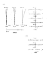
- FIG. 5A is a diagram illustrating various aberrations in the wide-angle end state of the variable magnification optical system according to the first example.
- FIG. 9A is a diagram illustrating various aberrations in the infinite focus state, and FIG. It is a coma aberration figure when correct
- FIG. 5A is a diagram illustrating various aberrations in the intermediate focal length state of the variable magnification optical system according to the first example.
- FIG. 9A is a diagram illustrating various aberrations in the infinite focus state, and FIG. It is a coma aberration figure when blurring correction is performed.
- FIG. 9A is a diagram illustrating various aberrations in the wide-angle end state of the variable magnification optical system according to the first example.
- FIG. 9A is a diagram illustrating various aberrations in the infinite focus state, and FIG. It is a coma aberration figure when blurring correction is performed.
- FIG. 9A is a diagram illustrating various aberrations in the wide-angle
- FIG. 5A is a diagram illustrating various aberrations in the telephoto end state of the variable magnification optical system according to the first example.
- FIG. 9A is a diagram illustrating various aberrations in the infinite focus state, and FIG. It is a coma aberration figure when correct
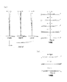
- FIG. 7A is a diagram illustrating various aberrations in the wide-angle end state of the variable magnification optical system according to the second example, where FIG.
- FIG. 9A is a diagram illustrating various aberrations in the infinite focus state, and FIG. It is a coma aberration figure when correct
- FIG. 7A is a diagram illustrating various aberrations in the intermediate focal length state of the variable magnification optical system according to the second example, where FIG. 9A is a diagram illustrating various aberrations in the infinite focus state, and FIG. It is a coma aberration figure when blurring correction is performed.
- FIG. 5A is a diagram illustrating various aberrations in the telephoto end state of the variable magnification optical system according to Example 2, wherein FIG. 9A is a diagram illustrating various aberrations in the infinite focus state, and FIG. It is a coma aberration figure when correct
- FIG. 7A is a diagram illustrating various aberrations in the wide-angle end state of the variable magnification optical system according to the third example, where FIG. 9A is a diagram illustrating various aberrations in the infinite focus state, and FIG. It is a coma aberration figure when correct
- FIG. 7A is a diagram illustrating various aberrations in the intermediate focal length state of the variable magnification optical system according to the third example, where FIG. 9A is a diagram illustrating various aberrations in the infinite focus state, and FIG. It is a coma aberration figure when blurring correction is performed.
- FIG. 9A is a diagram illustrating various aberrations in the wide-angle end state of the variable magnification optical system according to the third example, where FIG. 9A is a diagram illustrating various aberrations in the infinite focus state, and FIG. It is a coma aberration figure when blurring correction is performed.
- FIG. 9A is a diagram illustrating various aberrations in the infinite focus state
- FIG. 7A is a diagram illustrating various aberrations in the telephoto end state of the variable magnification optical system according to the third example, where FIG. 9A is a diagram illustrating various aberrations in the infinite focus state, and FIG. It is a coma aberration figure when correct
- FIG. 7A is a diagram illustrating various aberrations in the wide-angle end state of the variable magnification optical system according to the fourth example, where FIG. 9A is a diagram illustrating all aberrations in the infinite focus state, and FIG. It is a coma aberration figure when correct
- FIG. 9A is a diagram illustrating various aberrations in the wide-angle end state of the variable magnification optical system according to the fourth example, where FIG. 9A is a diagram illustrating all aberrations in the infinite focus state, and FIG. It is a coma aberration figure when correct
- FIG. 7A is a diagram illustrating various aberrations in the intermediate focal length state of the variable magnification optical system according to the fourth example, where FIG. 9A is a diagram illustrating various aberrations in the infinite focus state, and FIG. It is a coma aberration figure when blurring correction is performed.
- FIG. 7A is a diagram illustrating various aberrations in the telephoto end state of the variable magnification optical system according to the fourth example, where FIG. 9A is a diagram illustrating various aberrations in the infinite focus state, and FIG. It is a coma aberration figure when correct
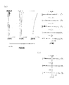
- FIG. 7A is a diagram illustrating various aberrations of the variable magnification optical system according to Example 5 in the wide-angle end state, where FIG. 9A is a diagram illustrating aberrations in an infinite focus state, and FIG. It is a coma aberration figure when correct
- FIG. 7A is a diagram illustrating various aberrations in the intermediate focal length state of the variable magnification optical system according to the fifth example, where FIG. 9A is a diagram illustrating various aberrations in the infinite focus state, and FIG. It is a coma aberration figure when blurring correction is performed.
- FIG. 6A is a diagram illustrating various aberrations of the zoom optical system according to Example 5 in the telephoto end state, where FIG.
- FIG. 5A is a diagram illustrating aberrations in the infinite focus state, and FIG. It is a coma aberration figure when correct
- a sectional view of a camera carrying the above-mentioned variable magnification optical system is shown.
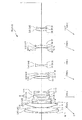
- the variable magnification optical system ZL includes, in order from the object side, a first lens group G1 having a positive refractive power, a second lens group G2 having a negative refractive power, A third lens group G3 having a positive refractive power, a fourth lens group G4 having a negative refractive power, and a fifth lens group G5 having a positive refractive power are configured.
- the zoom optical system ZL it is desirable to move the first lens group G1 with respect to the image plane I along the optical axis during zooming. With this configuration, it is possible to reduce aberration fluctuations during zooming.
- the refractive power of the first lens group G1 can be weakened, it is possible to reduce the deterioration of aberration when decentering due to manufacturing errors occurs.
- This variable magnification optical system ZL may be at least part of the second lens group G2 to the fifth lens group G5 (a plurality of lens groups or any one lens group, It may be desirable to move the lens so as to include a component orthogonal to the optical axis. At this time, it is more desirable to move at least a part of the second lens group G2 so as to include a component orthogonal to the optical axis. With this configuration, camera shake correction can be performed with a lens having a small diameter, so that the size of the lens barrel can be reduced.
- variable magnification optical system ZL satisfies the following conditional expression (1).
- f1 Focal length of the first lens group G1
- f2 Focal length of the second lens group G2
- Conditional expression (1) defines an appropriate focal length of the first lens group G1 with respect to the focal length of the second lens group G2. By satisfying conditional expression (1), it is possible to satisfactorily correct spherical aberration and chromatic aberration in the telephoto end state. If the lower limit of conditional expression (1) is not reached, the refractive power of the first lens group G1 becomes large, and it becomes difficult to correct spherical aberration and chromatic aberration in the telephoto end state, which is not preferable. If the lower limit of conditional expression (1) is 4.45, the effect of the present application can be ensured.
- the refractive power of the first lens group G1 becomes small, which leads to an increase in the total length, which is not preferable. If the upper limit of conditional expression (1) is 5.30, the effect of the present application can be ensured.
- f1 Focal length of the first lens group G1
- f3 Focal length of the third lens group G3
- Conditional expression (2) defines an appropriate focal length of the first lens group G1 with respect to the focal length of the third lens group G3. By satisfying conditional expression (2), it is possible to satisfactorily correct spherical aberration and chromatic aberration in the telephoto end state. If the lower limit of conditional expression (2) is not reached, the refractive power of the first lens group G1 becomes large, and it becomes difficult to correct spherical aberration and chromatic aberration in the telephoto end state. If the lower limit value of conditional expression (2) is 2.20, the effect of the present application can be ensured.
- conditional expression (2) when the value exceeds the upper limit value of the conditional expression (2), the refractive power of the first lens group G1 becomes small, which leads to an increase in the total length, which is not preferable. If the upper limit of conditional expression (2) is 4.35, the effect of the present application can be ensured.
- variable magnification optical system ZL satisfies the following conditional expression (3).
- Conditional expression (3) defines an appropriate focal length of the third lens group G3 with respect to the focal length of the fourth lens group G4. By satisfying conditional expression (3), it is possible to satisfactorily correct spherical aberration and chromatic aberration in the telephoto end state. If the lower limit of conditional expression (3) is not reached, the refractive power of the third lens group G3 becomes large, and it becomes difficult to correct spherical aberration and chromatic aberration in the telephoto end state. If the lower limit value of conditional expression (3) is 0.22, the effect of the present application can be ensured.
- conditional expression (3) when the value exceeds the upper limit value of the conditional expression (3), the refractive power of the third lens group G3 becomes small, which leads to an increase in the total length, which is not preferable. If the upper limit value of conditional expression (3) is 0.85, the effect of the present application can be ensured.
- Conditional expression (4) defines an appropriate focal length of the fourth lens group G4 with respect to the focal length of the fifth lens group G5. By satisfying conditional expression (4), it is possible to satisfactorily correct curvature of field and distortion in the wide-angle end state. If the lower limit of conditional expression (4) is not reached, the refractive power of the fourth lens group G4 becomes large, and it becomes difficult to correct chromatic aberration in the telephoto end state. If the lower limit of conditional expression (4) is 0.88, the effect of the present application can be ensured. On the other hand, exceeding the upper limit value of conditional expression (4) is not preferable because the refractive power of the fifth lens group G5 becomes large and it becomes difficult to correct curvature of field and distortion in the wide-angle end state. If the upper limit of conditional expression (4) is 1.52, the effect of the present application can be ensured.
- the zoom optical system ZL preferably has an aperture stop S on the image side with respect to the second lens group G2. At this time, it is desirable to have an aperture stop S between the third lens group G3 and the fifth lens group G5. Furthermore, it is desirable to have an aperture stop S between the third lens group G3 and the fourth lens group G4. With this configuration, coma and curvature of field can be favorably corrected.
- This zoom optical system ZL desirably moves at least a part of the third lens group G3 along the optical axis during focusing.
- the zoom optical system ZL it is desirable that the second lens group G2 is fixed with respect to the image plane I during zooming.
- the configuration of the lens barrel in zooming can be simplified, and the size of the lens barrel can be reduced.
- this zoom optical system ZL it is preferable that all lens surfaces are spherical surfaces. This configuration is preferable because it facilitates lens processing and assembly adjustment, and prevents deterioration in optical performance due to errors in processing and assembly adjustment. Further, even when the image plane is deviated, it is preferable because there is little deterioration in drawing performance.
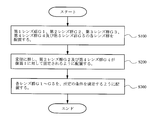
- the lenses are arranged to prepare the lens groups G1 to G5, respectively (step S100).
- the first lens group G1 is arranged to move along the optical axis (step S200).
- at least a part of the second lens group G2 to the fifth lens group G5 is arranged so as to move including a component orthogonal to the optical axis (step S300).
- the lens groups G1 to G5 are arranged so as to satisfy the conditional expressions (1) and (2) described above (step S400).
- a cemented lens in which a negative meniscus lens L11 having a convex surface facing the object side and a biconvex lens L12 are cemented, and a positive lens having a convex surface facing the object side.
- a biconcave lens L25 is arranged to form the second lens group G2, and a biconvex lens L31 and a cemented lens in which a negative meniscus lens L32 having a convex surface facing the object side and a biconvex lens L33 are arranged are arranged to form a third lens.
- a cemented lens obtained by cementing a plano-concave lens L56 having a concave surface directed toward the object side and a negative meniscus lens L57 having a concave surface directed toward the object side are disposed to form a fifth lens group G5.
- the lens groups thus prepared are arranged in the above-described procedure to manufacture the variable magnification optical system ZL.
- the variable magnification optical system ZL also has a first lens group G1 having a positive refractive power and a second lens group having a negative refractive power in order from the object side. G2, a third lens group G3 having a positive refractive power, a fourth lens group G4 having a negative refractive power, and a fifth lens group G5 having a positive refractive power. .
- the zoom optical system ZL desirably moves the first lens group G1 relative to the image plane I along the optical axis during zooming. With this configuration, it is possible to reduce aberration fluctuations during zooming. Since the refractive power of the first lens group G1 can be weakened, it is possible to reduce the deterioration of aberration when decentering due to a manufacturing error occurs.
- This variable magnification optical system ZL may be at least part of the second lens group G2 to the fifth lens group G5 (a plurality of lens groups or any one lens group, It may be desirable to move the lens so as to include a component orthogonal to the optical axis. At this time, it is more desirable to move at least a part of the second lens group G2 so as to include a component orthogonal to the optical axis. With this configuration, camera shake correction can be performed with a lens having a small diameter, so that the size of the lens barrel can be reduced.
- variable magnification optical system ZL satisfies the following conditional expression (5).
- f1 Focal length of the first lens group G1
- f2 Focal length of the second lens group G2
- Conditional expression (5) defines an appropriate focal length of the first lens group G1 with respect to the focal length of the second lens group G2. By satisfying conditional expression (5), it is possible to satisfactorily correct spherical aberration and chromatic aberration in the telephoto end state. If the lower limit of conditional expression (5) is not reached, the refractive power of the first lens group G1 becomes large, and it becomes difficult to correct spherical aberration and chromatic aberration in the telephoto end state. If the lower limit of conditional expression (5) is 4.45, the effect of the present application can be ensured.
- conditional expression (5) when the value exceeds the upper limit value of the conditional expression (5), the refractive power of the first lens group G1 becomes small, which leads to an increase in the total length. If the upper limit value of conditional expression (5) is 5.30, the effect of the present application can be ensured.
- Conditional expression (6) defines an appropriate focal length of the third lens group G3 with respect to the focal length of the fifth lens group G5. By satisfying conditional expression (6), it is possible to satisfactorily correct spherical aberration and chromatic aberration in the telephoto end state. If the lower limit of conditional expression (6) is not reached, the refractive power of the third lens group G3 becomes large, and it becomes difficult to correct spherical aberration and chromatic aberration at the telephoto end, which is not preferable. If the lower limit value of conditional expression (6) is 0.24, the effect of the present application can be ensured.
- conditional expression (6) when the value exceeds the upper limit value of the conditional expression (6), the refractive power of the third lens group G3 is reduced, which leads to an increase in the total length, which is not preferable. If the upper limit value of conditional expression (6) is 1.00, the effect of the present application can be ensured.
- variable magnification optical system ZL satisfies the following conditional expression (7).
- f1 Focal length of the first lens group G1
- f4 Focal length of the fourth lens group G4
- Conditional expression (7) defines an appropriate focal length of the first lens group G1 with respect to the focal length of the fourth lens group G4. By satisfying conditional expression (7), it is possible to satisfactorily correct spherical aberration and chromatic aberration in the telephoto end state. If the lower limit of conditional expression (7) is not reached, the refractive power of the first lens group G1 becomes large, and it becomes difficult to correct spherical aberration and chromatic aberration in the telephoto end state. If the lower limit value of conditional expression (7) is 0.77, the effect of the present application can be ensured.
- conditional expression (7) when the value exceeds the upper limit value of the conditional expression (7), the refractive power of the first lens group G1 becomes small, which leads to an increase in the total length, which is not preferable. If the upper limit of conditional expression (7) is 2.45, the effect of the present application can be ensured.
- f2 Focal length of the second lens group G2
- f4 Focal length of the fourth lens group G4
- Conditional expression (8) defines an appropriate focal length of the second lens group G2 with respect to the focal length of the fourth lens group G4.
- conditional expression (8) if the upper limit value of conditional expression (8) is exceeded, the refractive power of the fourth lens group G4 increases, and it becomes difficult to correct chromatic aberration at the telephoto end. If the upper limit of conditional expression (8) is 0.55, the effect of the present application can be ensured.
- the zoom optical system ZL preferably has an aperture stop S on the image side with respect to the second lens group G2. At this time, it is desirable to have an aperture stop S between the third lens group G3 and the fifth lens group G5. Furthermore, it is desirable to have an aperture stop S between the third lens group G3 and the fourth lens group G4. With this configuration, coma and curvature of field can be favorably corrected.
- This zoom optical system ZL desirably moves at least a part of the third lens group G3 along the optical axis during focusing.
- the zoom optical system ZL it is desirable that the second lens group G2 is fixed with respect to the image plane I during zooming.
- the configuration of the lens barrel in zooming can be simplified, and the size of the lens barrel can be reduced.
- this zoom optical system ZL it is preferable that all lens surfaces are spherical surfaces. This configuration is preferable because it facilitates lens processing and assembly adjustment, and prevents deterioration in optical performance due to errors in processing and assembly adjustment. Further, even when the image plane is deviated, it is preferable because there is little deterioration in drawing performance.
- the lenses are arranged to prepare the lens groups G1 to G5, respectively (step S100).
- the first lens group G1 is arranged to move along the optical axis (step S200).
- at least a part of the second lens group G2 to the fifth lens group G5 is arranged so as to move including a component orthogonal to the optical axis (step S300).
- the lens groups G1 to G5 are arranged so as to satisfy the conditional expressions (5) and (6) described above (step S400).
- a cemented lens in which a negative meniscus lens L11 having a convex surface facing the object side and a biconvex lens L12 are cemented, and a positive lens having a convex surface facing the object side.
- a biconcave lens L25 is arranged to form the second lens group G2, and a biconvex lens L31 and a cemented lens in which a negative meniscus lens L32 having a convex surface facing the object side and a biconvex lens L33 are arranged are arranged to form a third lens.
- a cemented lens obtained by cementing a plano-concave lens L56 having a concave surface directed toward the object side and a negative meniscus lens L57 having a concave surface directed toward the object side are disposed to form a fifth lens group G5.
- the lens groups thus prepared are arranged in the above-described procedure to manufacture the variable magnification optical system ZL.
- the variable magnification optical system ZL also has a first lens group G1 having a positive refractive power and a second lens group having a negative refractive power in order from the object side. G2, a third lens group G3 having a positive refractive power, a fourth lens group G4 having a negative refractive power, and a fifth lens group G5 having a positive refractive power. .
- the zoom optical system ZL it is desirable that the second lens group G2 is fixed with respect to the image plane during zooming. With this configuration, the amount of movement of each lens group during zooming can be reduced. By fixing the second lens group G2, it is possible to reduce the influence of eccentricity due to manufacturing errors.
- variable magnification optical system ZL satisfies the following conditional expression (9).
- Conditional expression (9) defines an appropriate focal length of the second lens group G2 with respect to the focal length of the entire variable magnification optical system ZL in the telephoto end state.
- conditional expression (9) By satisfying conditional expression (9), coma aberration in the wide-angle end state can be corrected well. If the lower limit of conditional expression (9) is not reached, the refractive power of the second lens group G2 becomes large, and it becomes difficult to correct coma in the wide-angle end state, which is not preferable. If the lower limit value of conditional expression (9) is 10.0, the effect of the present application can be ensured.
- This zoom optical system ZL preferably satisfies the following conditional expression (10).
- Conditional expression (10) defines an appropriate focal length of the fourth lens group G4 with respect to the focal length of the entire variable magnification optical system ZL in the telephoto end state.
- conditional expression (10) it is possible to satisfactorily correct spherical aberration and chromatic aberration in the telephoto end state. If the lower limit of conditional expression (10) is not reached, the refractive power of the fourth lens group G4 becomes large, and correction of chromatic aberration at the telephoto end becomes difficult, which is not preferable. If the lower limit value of conditional expression (10) is 4.0, the effect of the present application can be ensured.
- conditional expression (10) is 8.0, the effect of the present application can be ensured.
- Conditional expression (11) defines an appropriate focal length of the fourth lens group G4 with respect to the focal length of the fifth lens group G5. By satisfying conditional expression (11), it is possible to satisfactorily correct curvature of field and distortion in the wide-angle end state. If the lower limit of conditional expression (11) is not reached, the refractive power of the fourth lens group G4 becomes large, and it becomes difficult to correct chromatic aberration in the telephoto end state, which is not preferable. If the lower limit of conditional expression (11) is 0.9, the effect of the present application can be ensured.
- conditional expression (11) is 1.6, the effect of the present application can be ensured.
- Conditional expression (12) defines an appropriate focal length of the second lens group G2 with respect to the focal length of the fifth lens group G5. By satisfying conditional expression (12), it is possible to satisfactorily correct curvature of field and distortion in the wide-angle end state. If the lower limit of conditional expression (12) is not reached, the refractive power of the second lens group G2 becomes large, and it is difficult to correct coma in the wide-angle end state, which is not preferable. If the lower limit of conditional expression (12) is 0.4, the effect of the present application can be ensured.
- conditional expression (12) On the contrary, if the upper limit value of conditional expression (12) is exceeded, the refractive power of the fifth lens group G5 becomes large, and it becomes difficult to correct curvature of field and distortion in the wide-angle end state, which is not preferable. If the upper limit of conditional expression (12) is 0.7, the effect of the present application can be ensured. If the upper limit of conditional expression (12) is 0.6, the effect of the present application can be further ensured.
- the zoom optical system ZL preferably has an aperture stop S on the image side with respect to the second lens group G2. At this time, it is desirable to have an aperture stop S between the third lens group G3 and the fifth lens group G5. Furthermore, it is desirable to have an aperture stop S between the third lens group G3 and the fourth lens group G4. With this configuration, coma and curvature of field can be favorably corrected.
- This zoom optical system ZL desirably moves at least a part of the third lens group G3 along the optical axis during focusing.
- This variable magnification optical system ZL may be at least part of the second lens group G2 to the fifth lens group G5 (a plurality of lens groups or any one lens group, It may be desirable to move the lens so as to include a component orthogonal to the optical axis. At this time, it is desirable to move at least a part of the second lens group G2 so as to include a component orthogonal to the optical axis. With this configuration, camera shake correction can be performed with a lens having a small diameter, so that the size of the lens barrel can be reduced.
- this zoom optical system ZL it is preferable that all lens surfaces are spherical surfaces. This configuration is preferable because it facilitates lens processing and assembly adjustment, and prevents deterioration in optical performance due to errors in processing and assembly adjustment. Further, even when the image plane is deviated, it is preferable because there is little deterioration in drawing performance.
- the lenses are arranged to prepare the lens groups G1 to G5, respectively (step S100).
- the second lens group G2 is arranged so as to be fixed with respect to the image plane I (step S200).
- the lens groups G1 to G5 are arranged so as to satisfy the conditional expressions (9) and (10) described above (step S300).
- a cemented lens in which a negative meniscus lens L11 having a convex surface facing the object side and a biconvex lens L12 are cemented, and on the object side.
- a positive meniscus lens L13 having a convex surface is disposed to form a first lens group G1, a cemented lens in which a biconvex lens L21 and a biconcave lens L22 are cemented, a biconcave lens L23, and a positive meniscus lens L24 having a convex surface facing the object side.
- a cemented lens and a biconcave lens L25 are arranged to form the second lens group G2, and a biconvex lens L31 and a cemented lens in which a negative meniscus lens L32 having a convex surface facing the object side and a biconvex lens L33 are arranged.
- the third lens group G3 is a cemented lens in which a biconcave lens L41 and a positive meniscus lens L42 having a convex surface facing the object side are cemented.
- a fourth lens group G4 a cemented lens in which a biconvex lens L51, a plano-convex lens L52 having a convex surface facing the object side, a plano-concave lens L53 having a concave surface facing the image side, and a plano-convex lens L54 having a convex surface facing the object side are cemented
- the lens groups thus prepared are arranged in the above-described procedure to manufacture the variable magnification optical system ZL.
- the variable magnification optical system ZL also has a first lens group G1 having a positive refractive power and a second lens group having a negative refractive power in order from the object side. G2, a third lens group G3 having a positive refractive power, a fourth lens group G4 having a negative refractive power, and a fifth lens group G5 having a positive refractive power. .
- the zoom optical system ZL it is desirable that the second lens group G2 is fixed with respect to the image plane during zooming. With this configuration, the amount of movement of each lens group during zooming can be reduced. By fixing the second lens group G2, it is possible to reduce the influence of eccentricity due to manufacturing errors.
- This zoom optical system ZL preferably satisfies the following conditional expression (13).
- f1 Focal length of the first lens group G1
- f2 Focal length of the second lens group G2
- Conditional expression (13) defines an appropriate focal length of the first lens group G1 with respect to the focal length of the second lens group G2. By satisfying conditional expression (13), it is possible to satisfactorily correct spherical aberration and chromatic aberration in the telephoto end state. If the lower limit of conditional expression (13) is not reached, the refractive power of the first lens group G1 becomes large, and it becomes difficult to correct spherical aberration and chromatic aberration in the telephoto end state. If the lower limit value of conditional expression (13) is 3.0, the effect of the present application can be ensured.
- conditional expression (13) when the value exceeds the upper limit value of the conditional expression (13), the refractive power of the first lens group G1 becomes small, which leads to an increase in the total length, which is not preferable. If the upper limit of conditional expression (13) is 6.0, the effect of the present application can be ensured.
- f1 Focal length of the first lens group G1
- f4 Focal length of the fourth lens group G4
- Conditional expression (14) defines an appropriate focal length of the first lens group G1 with respect to the focal length of the fourth lens group G4. By satisfying conditional expression (14), it is possible to satisfactorily correct spherical aberration and chromatic aberration in the telephoto end state. If the lower limit of conditional expression (14) is not reached, the refractive power of the first lens group G1 becomes large, and it becomes difficult to correct spherical aberration and chromatic aberration in the telephoto end state. If the lower limit of conditional expression (14) is 1.4, the effect of the present application can be ensured.
- conditional expression (14) when the value exceeds the upper limit value of the conditional expression (14), the refractive power of the first lens group G1 becomes small, which leads to an increase in the total length, which is not preferable. If the upper limit of conditional expression (14) is 2.8, the effect of the present application can be ensured.
- f1 Focal length of the first lens group G1
- f5 Focal length of the fifth lens group G5
- Conditional expression (15) defines an appropriate focal length of the first lens group G1 with respect to the focal length of the fifth lens group G5. By satisfying conditional expression (15), it is possible to satisfactorily correct spherical aberration and chromatic aberration in the telephoto end state. If the lower limit of conditional expression (15) is not reached, the refractive power of the first lens group G1 becomes large, and it becomes difficult to correct spherical aberration and chromatic aberration in the telephoto end state. If the lower limit of conditional expression (15) is 2.0, the effect of the present application can be ensured.
- conditional expression (15) the refractive power of the fifth lens group G5 increases, and it becomes difficult to correct curvature of field and distortion at the wide angle end, which is not preferable. If the upper limit of conditional expression (15) is 3.0, the effect of the present application can be ensured.
- Conditional expression (16) defines an appropriate focal length of the fourth lens group G4 with respect to the focal length of the fifth lens group G5. By satisfying conditional expression (16), it is possible to satisfactorily correct curvature of field and distortion in the wide-angle end state. If the lower limit of conditional expression (16) is not reached, the refractive power of the fourth lens group G4 becomes large, and it becomes difficult to correct chromatic aberration in the telephoto end state, which is not preferable. If the lower limit of conditional expression (16) is 0.9, the effect of the present application can be ensured.
- conditional expression (16) exceeds the upper limit value of conditional expression (16) is not preferable because the refractive power of the fifth lens group G5 increases and it becomes difficult to correct curvature of field and distortion in the wide-angle end state. If the upper limit of conditional expression (16) is 1.6, the effect of the present application can be ensured.
- variable magnification optical system ZL satisfies the following conditional expression (17).
- Conditional expression (17) defines an appropriate focal length of the second lens group G2 with respect to the focal length of the fifth lens group G5. By satisfying conditional expression (17), it is possible to satisfactorily correct curvature of field and distortion in the wide-angle end state. If the lower limit of conditional expression (17) is not reached, the refractive power of the second lens group G2 becomes large, and it becomes difficult to correct coma in the wide-angle end state, which is not preferable. If the lower limit value of conditional expression (17) is 0.4, the effect of the present application can be ensured.
- conditional expression (17) if the upper limit value of conditional expression (17) is exceeded, the refractive power of the fifth lens group G5 becomes large, and it becomes difficult to correct field curvature and distortion in the wide-angle end state, which is not preferable. If the upper limit value of conditional expression (17) is 0.7, the effect of the present application can be ensured. If the upper limit of conditional expression (17) is 0.6, the effect of the present application can be further ensured.
- the zoom optical system ZL preferably has an aperture stop S on the image side with respect to the second lens group G2. At this time, it is desirable to have an aperture stop S between the third lens group G3 and the fifth lens group G5. Furthermore, it is desirable to have an aperture stop S between the third lens group G3 and the fourth lens group G4. With this configuration, coma and curvature of field can be favorably corrected.
- This zoom optical system ZL desirably moves at least a part of the third lens group G3 along the optical axis during focusing.
- This variable magnification optical system ZL may be at least part of the second lens group G2 to the fifth lens group G5 (a plurality of lens groups or any one lens group, It may be desirable to move the lens so as to include a component orthogonal to the optical axis. At this time, it is more desirable to move at least a part of the second lens group G2 so as to include a component orthogonal to the optical axis. With this configuration, camera shake correction can be performed with a lens having a small diameter, so that the size of the lens barrel can be reduced.
- this zoom optical system ZL it is preferable that all lens surfaces are spherical surfaces. This configuration is preferable because it facilitates lens processing and assembly adjustment, and prevents deterioration in optical performance due to errors in processing and assembly adjustment. Further, even when the image plane is deviated, it is preferable because there is little deterioration in drawing performance.
- the lenses are arranged to prepare the lens groups G1 to G5, respectively (step S100).
- the second lens group G2 is arranged so as to be fixed with respect to the image plane I (step S200).
- the lens groups G1 to G5 are arranged so as to satisfy the conditional expressions (13) and (14) (step S300).
- a cemented lens in which a negative meniscus lens L11 having a convex surface facing the object side and a biconvex lens L12 are cemented, and on the object side.
- a positive meniscus lens L13 having a convex surface is disposed to form a first lens group G1, a cemented lens in which a biconvex lens L21 and a biconcave lens L22 are cemented, a biconcave lens L23, and a positive meniscus lens L24 having a convex surface facing the object side.
- a cemented lens and a biconcave lens L25 are arranged to form the second lens group G2, and a biconvex lens L31 and a cemented lens in which a negative meniscus lens L32 having a convex surface facing the object side and a biconvex lens L33 are arranged.
- the third lens group G3 is a cemented lens in which a biconcave lens L41 and a positive meniscus lens L42 having a convex surface facing the object side are cemented.
- a fourth lens group G4 a cemented lens in which a biconvex lens L51, a plano-convex lens L52 having a convex surface facing the object side, a plano-concave lens L53 having a concave surface facing the image side, and a plano-convex lens L54 having a convex surface facing the object side are cemented
- the lens groups thus prepared are arranged in the above-described procedure to manufacture the variable magnification optical system ZL.
- the variable magnification optical system ZL also has a first lens group G1 having a positive refractive power and a second lens group having a negative refractive power in order from the object side. G2, a third lens group G3 having a positive refractive power, a fourth lens group G4 having a negative refractive power, and a fifth lens group G5 having a positive refractive power. .
- the zoom optical system ZL it is desirable that the second lens group G2 and the fourth lens group G4 are fixed with respect to the image plane during zooming. With this configuration, the configuration of the lens barrel in zooming can be simplified, and the size of the lens barrel can be reduced. In addition, it is possible to suppress degradation of optical performance due to manufacturing errors.
- variable magnification optical system ZL satisfies the following conditional expression (18).
- f1 Focal length of the first lens group G1
- f2 Focal length of the second lens group G2
- Conditional expression (18) defines an appropriate focal length of the first lens group G1 with respect to the focal length of the second lens group G2. By satisfying conditional expression (18), it is possible to satisfactorily correct spherical aberration and chromatic aberration at the telephoto end. If the lower limit of conditional expression (18) is not reached, the refractive power of the first lens group G1 becomes large, and it becomes difficult to correct spherical aberration and chromatic aberration in the telephoto end state, which is not preferable. When the lower limit value of conditional expression (18) is 2.25, the effect of the present application can be ensured.
- this zoom optical system ZL satisfies the following conditional expression (19).
- Conditional expression (19) defines an appropriate focal length of the fourth lens group G4 with respect to the focal length of the fifth lens group G5. By satisfying conditional expression (19), it is possible to satisfactorily correct field curvature and distortion in the wide-angle end state. If the lower limit of conditional expression (19) is not reached, the refractive power of the fourth lens group G4 becomes large and it becomes difficult to correct chromatic aberration at the telephoto end, which is not preferable. If the lower limit of conditional expression (19) is 0.44, the effect of the present application can be ensured.
- conditional expression (19) If the value exceeds the upper limit value of the conditional expression (19), the refractive power of the fifth lens group G5 is increased, which makes it difficult to correct curvature of field and distortion in the wide-angle end state. If the upper limit of conditional expression (19) is 1.63, the effect of the present application can be ensured.
- this zoom optical system ZL satisfies the following conditional expression (20).
- Conditional expression (20) defines an appropriate focal length of the first lens group G1 with respect to the focal length of the fourth lens group G4. By satisfying conditional expression (20), it is possible to satisfactorily correct spherical aberration and chromatic aberration in the telephoto end state. If the lower limit of conditional expression (20) is not reached, the refractive power of the first lens group G1 becomes large, and it becomes difficult to correct spherical aberration and chromatic aberration in the telephoto end state, which is not preferable. If the lower limit of conditional expression (20) is 0.79, the effect of the present application can be ensured.
- the refractive power of the first lens group G1 becomes small, which leads to an increase in the total length, which is not preferable. If the upper limit of conditional expression (20) is 2.71, the effect of the present application can be ensured.
- the zoom optical system ZL preferably has an aperture stop S on the image side with respect to the second lens group G2. At this time, it is desirable to have an aperture stop S between the third lens group G3 and the fifth lens group G5. Furthermore, it is desirable to have an aperture stop S between the third lens group G3 and the fourth lens group G4. With this configuration, coma and curvature of field can be favorably corrected.
- This zoom optical system ZL desirably moves at least a part of the third lens group G3 along the optical axis during focusing.
- This variable magnification optical system ZL may be at least part of the second lens group G2 to the fifth lens group G5 (a plurality of lens groups or any one lens group, It may be desirable to move the lens so as to include a component orthogonal to the optical axis. At this time, it is more desirable to move at least a part of the second lens group G2 so as to include a component orthogonal to the optical axis. With this configuration, camera shake correction can be performed with a lens having a small diameter, so that the size of the lens barrel can be reduced.
- this zoom optical system ZL it is preferable that all lens surfaces are spherical surfaces. This configuration is preferable because it facilitates lens processing and assembly adjustment, and prevents deterioration in optical performance due to errors in processing and assembly adjustment. Further, even when the image plane is deviated, it is preferable because there is little deterioration in drawing performance.
- the lenses are arranged to prepare the lens groups G1 to G5, respectively (step S100).
- the second lens group G2 and the fourth lens group G4 are arranged so as to be fixed with respect to the image plane I (step S200).
- the lens groups G1 to G5 are arranged so as to satisfy the conditional expressions (18) and (19) (step S300).
- a cemented lens in which a negative meniscus lens L11 having a convex surface facing the object side and a biconvex lens L12 are cemented, and on the object side.
- a positive meniscus lens L13 having a convex surface is disposed to form a first lens group G1, a cemented lens in which a biconvex lens L21 and a biconcave lens L22 are cemented, a biconcave lens L23, and a positive meniscus lens L24 having a convex surface facing the object side.
- a cemented lens and a biconcave lens L25 are arranged to form the second lens group G2, and a biconvex lens L31 and a cemented lens in which a negative meniscus lens L32 having a convex surface facing the object side and a biconvex lens L33 are arranged.
- the third lens group G3 is a cemented lens in which a biconcave lens L41 and a positive meniscus lens L42 having a convex surface facing the object side are cemented.
- a fourth lens group G4 a cemented lens in which a biconvex lens L51, a plano-convex lens L52 having a convex surface facing the object side, a plano-concave lens L53 having a concave surface facing the image side, and a plano-convex lens L54 having a convex surface facing the object side are cemented
- the lens groups thus prepared are arranged in the above-described procedure to manufacture the variable magnification optical system ZL.
- the variable magnification optical system ZL also has a first lens group G1 having a positive refractive power and a second lens group having a negative refractive power in order from the object side. G2, a third lens group G3 having a positive refractive power, a fourth lens group G4 having a negative refractive power, and a fifth lens group G5 having a positive refractive power. .
- the zoom optical system ZL it is desirable that the second lens group G2 and the fourth lens group G4 are fixed with respect to the image plane during zooming. With this configuration, the configuration of the lens barrel in zooming can be simplified, and the size of the lens barrel can be reduced. In addition, it is possible to suppress degradation of optical performance due to manufacturing errors.
- variable magnification optical system ZL satisfies the following conditional expression (21).
- Conditional expression (21) defines an appropriate focal length of the second lens group G2 with respect to the focal length of the third lens group G3. By satisfying conditional expression (21), coma aberration at the wide-angle end state, spherical aberration and chromatic aberration at the telephoto end can be corrected well. If the lower limit of conditional expression (21) is not reached, the refractive power of the second lens group G2 becomes large, and it is difficult to correct coma in the wide-angle end state, which is not preferable. If the lower limit value of conditional expression (21) is 0.47, the effect of the present application can be ensured.
- conditional expression (21) if the upper limit value of conditional expression (21) is exceeded, the refractive power of the third lens group G3 becomes large, and it becomes difficult to correct spherical aberration and chromatic aberration in the telephoto end state, which is not preferable.
- the upper limit value of conditional expression (21) is 0.76, the effect of the present application can be ensured.
- variable magnification optical system ZL satisfies the following conditional expression (22).
- Conditional expression (22) defines an appropriate focal length of the fourth lens group G4 with respect to the focal length of the fifth lens group G5. By satisfying conditional expression (22), it is possible to satisfactorily correct curvature of field and distortion in the wide-angle end state. If the lower limit of conditional expression (22) is not reached, the refractive power of the fourth lens group G4 becomes large, and it becomes difficult to correct chromatic aberration at the telephoto end, which is not preferable. If the lower limit value of conditional expression (22) is 0.44, the effect of the present application can be ensured.
- conditional expression (22) exceeds the upper limit value of conditional expression (22) because the refractive power of the fifth lens group G5 increases and it becomes difficult to correct curvature of field and distortion in the wide-angle end state. If the upper limit of conditional expression (22) is 1.63, the effect of the present application can be ensured.
- this zoom optical system ZL satisfies the following conditional expression (23).
- Conditional expression (23) defines an appropriate focal length of the third lens group G3 with respect to the focal length of the fourth lens group G4. By satisfying conditional expression (23), it is possible to satisfactorily correct spherical aberration and chromatic aberration in the telephoto end state. If the lower limit of conditional expression (23) is not reached, the refractive power of the third lens group G3 becomes large, and it becomes difficult to correct spherical aberration and chromatic aberration in the telephoto end state. If the lower limit value of conditional expression (23) is 0.31, the effect of the present application can be ensured.
- the zoom optical system ZL preferably has an aperture stop S on the image side with respect to the second lens group G2. At this time, it is desirable to have an aperture stop S between the third lens group G3 and the fifth lens group G5. Furthermore, it is desirable to have an aperture stop S between the third lens group G3 and the fourth lens group G4. With this configuration, coma and curvature of field can be favorably corrected.
- This zoom optical system ZL desirably moves at least a part of the third lens group G3 along the optical axis during focusing.
- This variable magnification optical system ZL may be at least part of the second lens group G2 to the fifth lens group G5 (a plurality of lens groups or any one lens group, It may be desirable to move the lens so as to include a component orthogonal to the optical axis. At this time, it is more desirable to move at least a part of the second lens group G2 so as to include a component orthogonal to the optical axis. With this configuration, camera shake correction can be performed with a lens having a small diameter, so that the size of the lens barrel can be reduced.
- this zoom optical system ZL it is preferable that all lens surfaces are spherical surfaces. This configuration is preferable because it facilitates lens processing and assembly adjustment, and prevents deterioration in optical performance due to errors in processing and assembly adjustment. Further, even when the image plane is deviated, it is preferable because there is little deterioration in drawing performance.
- the lenses are arranged to prepare the lens groups G1 to G5, respectively (step S100).
- the second lens group G2 and the fourth lens group G4 are arranged so as to be fixed with respect to the image plane I (step S200).
- the lens groups G1 to G5 are arranged so as to satisfy the conditional expressions (21) and (22) described above (step S300).
- a cemented lens in which a negative meniscus lens L11 having a convex surface facing the object side and a biconvex lens L12 are cemented, and on the object side.
- a positive meniscus lens L13 having a convex surface is disposed to form a first lens group G1, a cemented lens in which a biconvex lens L21 and a biconcave lens L22 are cemented, a biconcave lens L23, and a positive meniscus lens L24 having a convex surface facing the object side.
- a cemented lens and a biconcave lens L25 are arranged to form the second lens group G2, and a biconvex lens L31 and a cemented lens in which a negative meniscus lens L32 having a convex surface facing the object side and a biconvex lens L33 are arranged.
- the third lens group G3 is a cemented lens in which a biconcave lens L41 and a positive meniscus lens L42 having a convex surface facing the object side are cemented.
- a fourth lens group G4 a cemented lens in which a biconvex lens L51, a plano-convex lens L52 having a convex surface facing the object side, a plano-concave lens L53 having a concave surface facing the image side, and a plano-convex lens L54 having a convex surface facing the object side are cemented
- the lens groups thus prepared are arranged in the above-described procedure to manufacture the variable magnification optical system ZL.
- the variable magnification optical system ZL also has a first lens group G1 having a positive refractive power and a second lens group having a negative refractive power in order from the object side. G2, a third lens group G3 having a positive refractive power, a fourth lens group G4 having a negative refractive power, and a fifth lens group G5 having a positive refractive power. .
- the zoom optical system ZL it is desirable to move the first lens group G1 with respect to the image plane I along the optical axis during zooming. With this configuration, it is possible to reduce aberration fluctuations during zooming.
- the refractive power of the first lens group G1 can be weakened, it is possible to reduce the deterioration of aberration when decentering due to manufacturing errors occurs.
- This variable magnification optical system ZL may be at least part of the second lens group G2 to the fifth lens group G5 (a plurality of lens groups or any one lens group, It may be desirable to move the lens so as to include a component orthogonal to the optical axis. At this time, it is more desirable to move at least a part of the second lens group G2 so as to include a component orthogonal to the optical axis. With this configuration, camera shake correction can be performed with a lens having a small diameter, so that the size of the lens barrel can be reduced.
- variable magnification optical system ZL satisfies the following conditional expression (24).
- Conditional expression (24) defines an appropriate focal length of the first lens group G1 with respect to the focal length of the second lens group G2. By satisfying conditional expression (24), it is possible to satisfactorily correct spherical aberration and chromatic aberration in the telephoto end state. If the lower limit of conditional expression (24) is not reached, the refractive power of the first lens group G1 becomes large, and it becomes difficult to correct spherical aberration and chromatic aberration in the telephoto end state. If the lower limit value of conditional expression (24) is 4.45, the effect of the present application can be ensured.
- conditional expression (24) if the upper limit value of conditional expression (24) is exceeded, the refractive power of the first lens group G1 will decrease, leading to an increase in the overall length, which is not preferable. If the upper limit value of conditional expression (24) is 5.30, the effect of the present application can be ensured.
- variable magnification optical system ZL satisfies the following conditional expression (25).
- Conditional expression (25) defines an appropriate focal length of the first lens group G1 with respect to the focal length of the third lens group G3. By satisfying conditional expression (25), it is possible to satisfactorily correct spherical aberration and chromatic aberration in the telephoto end state. If the lower limit of conditional expression (25) is not reached, the refractive power of the first lens group G1 becomes large, and it becomes difficult to correct spherical aberration and chromatic aberration in the telephoto end state. If the lower limit value of conditional expression (25) is 2.20, the effect of the present application can be ensured.
- conditional expression (25) if the upper limit value of conditional expression (25) is exceeded, the refractive power of the first lens group G1 becomes small, leading to an increase in the total length, which is not preferable. If the upper limit of conditional expression (25) is 4.35, the effect of the present application can be ensured.
- This zoom optical system ZL preferably satisfies the following conditional expression (26).
- Conditional expression (26) defines an appropriate focal length of the third lens group G3 with respect to the focal length of the fourth lens group G4. By satisfying conditional expression (26), spherical aberration and chromatic aberration in the telephoto end state can be corrected well. If the lower limit of conditional expression (26) is not reached, the refractive power of the third lens group G3 becomes large, and it becomes difficult to correct spherical aberration and chromatic aberration in the telephoto end state. If the lower limit value of conditional expression (26) is 0.22, the effect of the present application can be ensured.
- conditional expression (26) if the upper limit value of conditional expression (26) is exceeded, the refractive power of the third lens group G3 will decrease, leading to an increase in the overall length, which is not preferable. If the upper limit value of conditional expression (26) is 0.85, the effect of the present application can be ensured.
- variable magnification optical system ZL satisfies the following conditional expression (27).
- Conditional expression (27) defines an appropriate focal length of the fourth lens group G4 with respect to the focal length of the fifth lens group G5. By satisfying conditional expression (27), it is possible to satisfactorily correct field curvature and distortion in the wide-angle end state. If the lower limit of conditional expression (27) is not reached, the refractive power of the fourth lens group G4 becomes large, and it becomes difficult to correct chromatic aberration in the telephoto end state, which is not preferable. If the lower limit value of conditional expression (27) is 0.88, the effect of the present application can be ensured.
- conditional expression (27) exceeds the upper limit value of conditional expression (27) because the refractive power of the fifth lens group G5 increases and it becomes difficult to correct curvature of field and distortion in the wide-angle end state. If the upper limit of conditional expression (27) is 1.52, the effect of the present application can be ensured.
- the zoom optical system ZL preferably has an aperture stop S on the image side with respect to the second lens group G2. At this time, it is desirable to have an aperture stop S between the third lens group G3 and the fifth lens group G5. Furthermore, it is desirable to have an aperture stop S between the third lens group G3 and the fourth lens group G4. With this configuration, coma and curvature of field can be favorably corrected.
- This zoom optical system ZL desirably moves at least a part of the third lens group G3 along the optical axis during focusing.
- the zoom optical system ZL it is desirable that the second lens group G2 is fixed with respect to the image plane I during zooming.
- the configuration of the lens barrel in zooming can be simplified, and the size of the lens barrel can be reduced.
- this zoom optical system ZL it is preferable that all lens surfaces are spherical surfaces. This configuration is preferable because it facilitates lens processing and assembly adjustment, and prevents deterioration in optical performance due to errors in processing and assembly adjustment. Further, even when the image plane is deviated, it is preferable because there is little deterioration in drawing performance.
- the variable magnification optical system ZL includes at least one layer formed by a wet process on at least one of the optical surfaces in the nth lens group Gn (the fifth lens group G5 in the present embodiment).
- a protective film is applied.
- the antireflection film applied to the variable magnification optical system ZL is a multilayer film, and the outermost surface layer of the multilayer film is preferably a layer formed using a wet process.
- variable magnification optical system ZL it is preferable to satisfy the following conditional expression (28), where nd is the refractive index of the layer formed by the wet process at the d-line (wavelength 587.6 nm).
- conditional expression 28
- nd is the refractive index of the layer formed by the wet process at the d-line (wavelength 587.6 nm).
- the antireflection film is not limited to a wet process, and may include at least one layer having a refractive index of 1.30 or less (by a dry process or the like). Even if comprised in this way, the effect similar to the case where a wet process is used can be acquired.
- the layer having a refractive index of 1.30 or less is preferably the outermost surface layer among the layers constituting the multilayer film.
- the light beam BM from the object side is incident on the variable magnification optical system ZL1
- the light is an object side lens surface (first ghost generation surface in the biconvex lens L55, and is assigned surface number 29.
- the reflected light is reflected again by the image-side lens surface of the plano-convex lens L54 (second ghost generation surface, corresponding to surface number 28) and reaches the image surface I, and the ghost is reflected. Will be generated.
- the antireflection film will be described in detail later, the antireflection film according to each example has a multilayer structure including seven layers, and the seventh layer of the outermost surface layer is formed by using a wet process and is refracted with respect to the d line. The rate is 1.26 (see Table 16 below).
- the lenses are arranged to prepare the lens groups G1 to G5, respectively (step S100).
- the first lens group G1 is arranged to move along the optical axis (step S200).
- at least a part of the second lens group G2 to the fifth lens group G5 is arranged so as to move including a component orthogonal to the optical axis (step S300).
- the lens groups G1 to G5 are arranged so as to satisfy the conditional expressions (24) and (25) described above (step S400).
- a cemented lens in which a negative meniscus lens L11 having a convex surface facing the object side and a biconvex lens L12 are cemented, and on the object side.
- a positive meniscus lens L13 having a convex surface is disposed to form a first lens group G1, a cemented lens in which a biconvex lens L21 and a biconcave lens L22 are cemented, a biconcave lens L23, and a positive meniscus lens L24 having a convex surface facing the object side.
- a cemented lens and a biconcave lens L25 are arranged to form the second lens group G2, and a biconvex lens L31 and a cemented lens in which a negative meniscus lens L32 having a convex surface facing the object side and a biconvex lens L33 are arranged.
- the third lens group G3 is a cemented lens in which a biconcave lens L41 and a positive meniscus lens L42 having a convex surface facing the object side are cemented.
- a fourth lens group G4 a cemented lens in which a biconvex lens L51, a plano-convex lens L52 having a convex surface facing the object side, a plano-concave lens L53 having a concave surface facing the image side, and a plano-convex lens L54 having a convex surface facing the object side are cemented
- the lens groups thus prepared are arranged in the above-described procedure to manufacture the variable magnification optical system ZL.
- This camera 1 is a so-called mirrorless camera of interchangeable lens provided with a variable magnification optical system ZL according to the present embodiment as a photographing lens 2.
- OLPF Optical Low Pass Filter
- a subject image is formed on the screen.
- the subject image is photoelectrically converted by the photoelectric conversion element provided in the imaging unit 3 to generate an image of the subject.
- EVF Electronic view finder
- variable power optical system ZL is applied to a single-lens reflex camera that has a quick return mirror in the camera body and observes a subject with a finder optical system. Even when the camera is mounted, the same effect as the camera 1 can be obtained.
- variable magnification optical system ZL having the 5-group and 6-group configurations is shown, but the above-described configuration conditions and the like can be applied to other group configurations such as the 7-group. Further, a configuration in which a lens or a lens group is added to the most object side, or a configuration in which a lens or a lens group is added to the most image side may be used.
- the lens group refers to a portion having at least one lens separated by an air interval that changes during zooming.
- a focusing lens group that performs focusing from an object at infinity to a short distance object by moving a single lens group, a plurality of lens groups, or a partial lens group in the optical axis direction may be used.
- the focusing lens group can be applied to autofocus, and is also suitable for driving a motor for autofocus (such as an ultrasonic motor).
- a motor for autofocus such as an ultrasonic motor
- the lens group or the partial lens group is moved so as to have a component in the direction perpendicular to the optical axis, or rotated (swinged) in the in-plane direction including the optical axis to prevent image blur caused by camera shake.
- a vibration lens group may be used.
- the lens surface may be formed as a spherical or flat surface or an aspherical surface.
- the lens surface is a spherical surface or a flat surface, as described above, lens processing and assembly adjustment are facilitated, and deterioration of optical performance due to errors in processing and assembly adjustment is prevented, which is preferable. Further, even when the image plane is deviated, it is preferable because there is little deterioration in drawing performance.
- the lens surface is an aspheric surface, the aspheric surface is an aspheric surface by grinding, a glass mold aspheric surface made of glass with an aspheric shape, or a composite aspheric surface made of resin with an aspheric shape on the glass surface. Any aspherical surface may be used.
- the lens surface may be a diffractive surface, and the lens may be a gradient index lens (GRIN lens) or a plastic lens.
- GRIN lens gradient index lens
- the aperture stop S is preferably disposed between the third lens group G3 and the fifth lens group G5.
- the aperture stop S does not have a member as an aperture stop, and plays a role in the lens frame. You may substitute.
- Each lens surface may be provided with an antireflection film having high transmittance in a wide wavelength range in order to reduce flare and ghost and achieve high optical performance with high contrast.
- the zoom optical system ZL of this embodiment has a zoom ratio of about 3.0 to 7.0.
- FIGS. 1, 6, 10, 14 and 18 are cross-sectional views showing the configuration and refractive power distribution of the variable magnification optical system ZL (ZL1 to ZL5) according to each example. Further, at the lower part of the sectional view of the variable magnification optical systems ZL1 to ZL5, the optical axis of each lens group G1 to G5 or G6 when changing magnification from the wide-angle end state (W) to the telephoto end state (T) is shown. The direction of movement along is indicated by arrows.
- the first lens group G1 is configured to move along the optical axis with respect to the image plane I during zooming.
- FIG. 1 is a diagram showing a configuration of a variable magnification optical system ZL1 according to the first example.
- the zoom optical system ZL1 shown in FIG. 1 includes, in order from the object side, a first lens group G1 having a positive refractive power, a second lens group G2 having a negative refractive power, and a first lens group having a positive refractive power.
- the third lens group G3 includes a third lens group G3, a fourth lens group G4 having a negative refractive power, and a fifth lens group G5 having a positive refractive power.
- the first lens group G1 includes, in order from the object side, a cemented lens in which a negative meniscus lens L11 having a convex surface facing the object side and a biconvex lens L12 are cemented, and a positive meniscus lens L13 having a convex surface facing the object side. It is configured.
- the second lens group G2 includes, in order from the object side, a cemented lens in which the biconvex lens L21 and the biconcave lens L22 are cemented, and a cemented lens in which the biconcave lens L23 and a positive meniscus lens L24 having a convex surface facing the object side are cemented. And it is comprised from the biconcave lens L25.
- the third lens group G3 includes, in order from the object side, a biconvex lens L31, and a cemented lens in which a negative meniscus lens L32 having a convex surface facing the object side and a biconvex lens L33 are cemented.
- the fourth lens group G4 is composed of a cemented lens in which, in order from the object side, a biconcave lens L41 and a positive meniscus lens L42 having a convex surface directed toward the object side are cemented.
- the fifth lens group G5 includes, in order from the object side, a biconvex lens L51, a planoconvex lens L52 with a convex surface facing the object side, a planoconcave lens L53 with a concave surface facing the image side, and a planoconvex lens L54 with a convex surface facing the object side.
- a biconvex lens L55 is cemented with a plano-concave lens L56 with a concave surface facing the object side, and a negative meniscus lens L57 with a concave surface facing the object side.
- the zoom optical system ZL1 when zooming from the wide-angle end state to the telephoto end state, the first lens group G1, the third lens group G3, and the fifth lens group G5 are arranged on the optical axis.
- the second lens group G2 and the fourth lens group G4 are fixed in the optical axis direction with respect to the image plane I.
- the aperture stop S is disposed on the object side of the fifth lens group G5 and moves together with the fifth lens group G5 upon zooming.
- Focusing from infinity to a close object is performed by moving the third lens group G3 to the image side.
- a cemented lens obtained by cementing the biconcave lens L23 of the second lens group G2 and the positive meniscus lens L24 having a convex surface toward the object side is used as an anti-vibration lens group. It is performed by moving so as to include a component in a direction perpendicular to the axis. It is to be noted that the focal length of the entire system is f, and the image stabilization coefficient (ratio of the amount of image movement on the imaging surface to the amount of movement of the image stabilization lens group VL in image blur correction) is K.
- the image stabilization coefficient is ⁇ 0.767 and the focal length is 81.6 (mm). Therefore, the image stabilization for correcting the rotational shake of 0.2 ° is performed.
- the moving amount of the lens group is ⁇ 0.371 (mm).
- the image stabilization coefficient is ⁇ 1.348 and the focal length is 200.0 (mm). Therefore, in order to correct 0.2 ° rotational shake.
- the amount of movement of the anti-vibration lens group is -0.518 (mm).
- the image stabilization coefficient is -2.103 and the focal length is 392.0 (mm).
- the moving amount of the anti-vibration lens group is ⁇ 0.651 (mm).
- ⁇ in the overall specifications is a zoom ratio
- f is a focal length of the entire system
- FNO is an F number
- 2 ⁇ is an angle of view
- Y is an image height
- TL is a total length.
- the total length TL represents the distance on the optical axis from the first surface of the lens surface to the image plane I when focusing on infinity.
- the first column m indicates the order (surface number) of the lens surfaces from the object side along the traveling direction of the light beam
- the second column r indicates the curvature radius of each lens surface
- d is the distance on the optical axis from each optical surface to the next optical surface (surface interval).
- the surface numbers 1 to 33 shown in Table 1 correspond to the numbers 1 to 33 shown in FIG.
- the lens group focal length indicates the start surface and focal length of each of the first to fifth lens groups G1 to G5.
- the focal length f, the radius of curvature r, the surface interval d, and other length units listed in all the following specification values are generally “mm”, but the optical system is proportionally enlarged or proportional. Since the same optical performance can be obtained even if the image is reduced, the present invention is not limited to this.
- the description of these symbols and the description of the specification table are the same in the following embodiments.
- the axial air gap D3 between the first lens group G4 and the fourth lens group G4, the axial air gap D4 between the fourth lens group G4 and the fifth lens group G5 and the aperture stop S moving together with the fourth lens group G4, and the back focus BF change during zooming.
- Table 2 below shows the values of the variable intervals D1 to D4 and the back focus BF at the respective focal lengths in the wide-angle end state, the intermediate focal length state, and the telephoto end state at the time of focusing on infinity.
- the back focus BF represents the distance on the optical axis from the most image side lens surface (the 33rd surface in FIG. 1) to the image surface I. This description is the same in the following embodiments.
- Table 3 shows values corresponding to the conditional expressions in the first embodiment.
- f1 is the focal length of the first lens group G1
- f2 is the focal length of the second lens group G2
- f4 is the focal length of the fourth lens group G4
- f5 is the fifth lens group G5.
- Each focal length is shown. The description of the above symbols is the same in the following embodiments.
- variable magnification optical system ZL1 satisfies all the conditional expressions (1) to (27).
- FIG. 2A shows an aberration diagram in the infinite focus state in the wide-angle end state of the first embodiment
- FIG. 3A shows an aberration diagram in the infinite focus state in the intermediate focal length state
- FIG. 4A shows an aberration diagram in the infinitely focused state in the telephoto end state
- FNO represents an F number
- A represents a half field angle
- the solid line shows the sagittal image plane
- the broken line shows the meridional image plane.
- the explanation of this aberration diagram is the same in the following examples.
- various aberrations are well corrected in each focal length state from the wide-angle end state to the telephoto end state, and it can be seen that the imaging performance is excellent.
- FIG. 5 shows the variable magnification optical system of the first embodiment, in which incident light rays are reflected by the first ghost generation surface and the second ghost generation surface to form ghosts and flares on the image plane I. It is a figure which shows an example of a mode to do.
- FIG. 6 is a diagram illustrating a configuration of the variable magnification optical system ZL2 according to the second example.
- the zoom optical system ZL2 shown in FIG. 6 includes, in order from the object side, a first lens group G1 having a positive refractive power, a second lens group G2 having a negative refractive power, and a first lens group having a positive refractive power.
- the third lens group G3 includes a fourth lens group G4 having a negative refractive power, a fifth lens group G5 having a positive refractive power, and a sixth lens group G6 having a negative refractive power. .
- the first lens group G1 includes, in order from the object side, a cemented lens in which a negative meniscus lens L11 having a convex surface facing the object side and a biconvex lens L12 are cemented, and a biconvex lens L13.
- the second lens group G2 includes, in order from the object side, a cemented lens in which a positive meniscus lens L21 having a concave surface facing the object side and a biconcave lens L22 are cemented, and a positive meniscus lens having a convex surface facing the biconcave lens L23 and the object side. It is composed of a cemented lens joined to L24 and a biconcave lens L25.
- the third lens group G3 includes, in order from the object side, a biconvex lens L31, and a cemented lens in which a biconvex lens L32 and a negative meniscus lens L33 having a concave surface facing the object side are cemented.
- the fourth lens group G4 includes a cemented lens in which a biconcave lens L41 and a biconvex lens L42 are cemented in order from the object side.
- the fifth lens group G5 includes, in order from the object side, a biconvex lens L51 and a cemented lens in which a biconvex lens L52 and a negative meniscus lens L53 having a concave surface facing the object side are cemented.
- the sixth lens group G6 includes a cemented lens in which a biconvex lens L61 and a biconcave lens L62 are cemented in order from the object side.
- the zoom optical system ZL2 has a first lens group G1, a third lens group G3, a fifth lens group G5, and a sixth lens group G6 during zooming from the wide-angle end state to the telephoto end state. Moves in the object direction on the optical axis, and the second lens group G2 and the fourth lens group G4 are fixed with respect to the image plane I in the optical axis direction.
- the aperture stop S is disposed on the object side of the fifth lens group G5 and moves together with the fifth lens group G5 upon zooming.
- Focusing from infinity to a close object is performed by moving the third lens group G3 to the image side.
- a cemented lens obtained by cementing the biconcave lens L23 of the second lens group G2 and the positive meniscus lens L24 having a convex surface toward the object side is used as an anti-vibration lens group. It is performed by moving so as to include a component in a direction perpendicular to the axis.
- the image stabilization coefficient is ⁇ 0.637 and the focal length is 72.0 (mm). Therefore, the image stabilization for correcting the rotational shake of 0.2 ° is performed.
- the moving amount of the lens group is ⁇ 0.395 (mm).
- the image stabilization coefficient is ⁇ 1.158 and the focal length is 200.0 (mm).
- the amount of movement of the anti-vibration lens group is ⁇ 0.603 (mm).
- the image stabilization coefficient is ⁇ 1.763 and the focal length is 390.0 (mm).
- the moving amount of the anti-vibration lens group is ⁇ 0.772 (mm).
- Table 4 below lists the values of the specifications of the second embodiment.
- the surface numbers 1 to 30 shown in Table 4 correspond to the numbers 1 to 30 shown in FIG.
- the lens group focal length indicates the start surface and focal length of each of the first to sixth lens groups G1 to G6.
- the fourth lens group G4 the axial air distance D3 between the fourth lens group G4 and the fifth lens group G5, the axial air distance D4 between the aperture stop S moving together with the fourth lens group G4, the fifth lens group G5 and the sixth lens group G6.
- the on-axis air distance D5 and the back focus BF change during zooming. Table 5 below shows the values of the variable distances D1 to D5 and the back focus BF at the respective focal lengths in the wide-angle end state, the intermediate focal length state, and the telephoto end state when focusing on infinity.
- Table 6 shows values corresponding to the conditional expressions in the second embodiment.
- variable magnification optical system ZL2 satisfies all the conditional expressions (1) to (27).
- FIG. 7A shows an aberration diagram in the infinite focus state in the wide-angle end state of the second embodiment
- FIG. 8A shows an aberration diagram in the infinite focus state in the intermediate focal length state
- FIG. 9A shows an aberration diagram in the infinitely focused state in the telephoto end state
- FIG. 8B shows a coma aberration diagram when image blur correction
- FIG. 10 is a diagram illustrating a configuration of the variable magnification optical system ZL3 according to the third example.
- the zoom optical system ZL3 shown in FIG. 10 includes, in order from the object side, a first lens group G1 having a positive refractive power, a second lens group G2 having a negative refractive power, and a first lens group having a positive refractive power.
- the third lens group G3 includes a fourth lens group G4 having a negative refractive power, a fifth lens group G5 having a positive refractive power, and a sixth lens group G6 having a negative refractive power. .
- the first lens group G1 includes, in order from the object side, a cemented lens in which a negative meniscus lens L11 having a convex surface facing the object side and a biconvex lens L12 are cemented, and a biconvex lens L13.
- the second lens group G2 includes, in order from the object side, a cemented lens in which a biconvex lens L21 and a biconcave lens L22 are cemented, and a cemented lens in which a positive meniscus lens L23 having a concave surface facing the object side and a biconcave lens L24 are cemented. And it is comprised from the biconcave lens L25.
- the third lens group G3 includes a biconvex lens L31 and a cemented lens in which the biconvex lens L32 and the biconcave lens L33 are cemented in order from the object side.
- the fourth lens group G4 is composed of a cemented lens in which, in order from the object side, a biconcave lens L41 and a positive meniscus lens L42 having a convex surface directed toward the object side are cemented.
- the fifth lens group G5 includes, in order from the object side, a cemented lens in which a negative meniscus lens L51 having a convex surface facing the object side and a biconvex lens L52 are cemented, and a negative lens having a concave surface facing the biconvex lens L53 and the object side.
- the sixth lens group G6 includes a cemented lens in which a biconvex lens L61 and a biconcave lens L62 are cemented in order from the object side.
- the zoom optical system ZL3 according to the third example has a first lens group G1, a third lens group G3, a fifth lens group G5, and a sixth lens group G6 when zooming from the wide-angle end state to the telephoto end state. Moves in the object direction on the optical axis, and the second lens group G2 and the fourth lens group G4 are fixed with respect to the image plane I in the optical axis direction.
- the aperture stop S is disposed on the object side of the fifth lens group G5 and moves together with the fifth lens group G5 upon zooming.
- Focusing from infinity to a close object is performed by moving the third lens group G3 to the image side.
- Image blur correction is performed by using the entire second lens group G2 as an anti-vibration lens group and moving the anti-vibration lens group so as to include a component in a direction perpendicular to the optical axis.
- the image stabilization coefficient in the wide-angle end state, is -1.972 and the focal length is 72.0 (mm). Therefore, the image stabilization for correcting the rotational shake of 0.2 ° is performed.
- the moving amount of the lens group is ⁇ 0.127 (mm).
- the image stabilization coefficient is ⁇ 3.534 and the focal length is 200.0 (mm). Therefore, in order to correct the 0.2 ° rotational blur.
- the amount of movement of the anti-vibration lens group is -0.198 (mm). Further, in the telephoto end state of the third embodiment, the image stabilization coefficient is ⁇ 5.379 and the focal length is 390.0 (mm). The moving amount of the anti-vibration lens group is ⁇ 0.253 (mm).
- Table 7 below lists the values of the specifications of the third example.
- the surface numbers 1 to 31 shown in Table 7 correspond to the numbers 1 to 31 shown in FIG.
- the lens group focal length indicates the start surface and focal length of each of the first to sixth lens groups G1 to G6.
- the on-axis air distance D5 and the back focus BF change during zooming. Table 8 below shows the values of the variable intervals D1 to D5 and the back focus BF at the respective focal lengths in the wide-angle end state, the intermediate focal length state, and the telephoto end state at the time of focusing on infinity.
- Table 9 shows values corresponding to the conditional expressions in the third embodiment.
- the zoom optical system ZL3 according to the third example satisfies all the conditional expressions (1) to (27).
- FIG. 11A shows an aberration diagram in the infinite focus state in the wide-angle end state of this third embodiment
- FIG. 12A shows an aberration diagram in the infinite focus state in the intermediate focal length state
- FIG. 13A shows an aberration diagram in the infinitely focused state in the telephoto end state
- FIG. 11A shows an aberration diagram in the infinite focus state in the wide-angle end state of this third embodiment
- FIG. 12A shows an aberration diagram in the infinite focus state in the intermediate focal length state.
- FIG. 11B shows a coma aberration diagram when image blur correction (shift amount of the image stabilizing lens group
- FIG. 14 is a diagram showing a configuration of a variable magnification optical system ZL4 according to the fourth example.
- the zoom optical system ZL4 shown in FIG. 14 includes, in order from the object side, a first lens group G1 having a positive refractive power, a second lens group G2 having a negative refractive power, and a first lens group having a positive refractive power.
- the third lens group G3 includes a fourth lens group G4 having a negative refractive power, a fifth lens group G5 having a positive refractive power, and a sixth lens group G6 having a negative refractive power. .
- the first lens group G1 includes, in order from the object side, a cemented lens in which a negative meniscus lens L11 having a convex surface facing the object side and a biconvex lens L12 are cemented, and a biconvex lens L13.
- the second lens group G2 includes, in order from the object side, a cemented lens in which the biconvex lens L21 and the biconcave lens L22 are cemented, and a cemented lens in which the biconcave lens L23 and a positive meniscus lens L24 having a convex surface facing the object side are cemented. And it is comprised from the biconcave lens L25.
- the third lens group G3 includes, in order from the object side, a biconvex lens L31, and a cemented lens in which a negative meniscus lens L32 having a convex surface facing the object side and a biconvex lens L33 are cemented.
- the fourth lens group G4 is composed of a cemented lens in which, in order from the object side, a biconcave lens L41 and a positive meniscus lens L42 having a convex surface directed toward the object side are cemented.
- the fifth lens group G5 includes, in order from the object side, a cemented lens in which a negative meniscus lens L51 having a convex surface facing the object side and a biconvex lens L52 are cemented, and a negative lens having a concave surface facing the biconvex lens L53 and the object side. It is composed of a cemented lens in which a meniscus lens L54 is cemented.
- the sixth lens group G6 includes a cemented lens in which a biconvex lens L61 and a biconcave lens L62 are cemented in order from the object side.
- the zoom optical system ZL4 according to the fourth example has a first lens group G1, a third lens group G3, a fifth lens group G5, and a sixth lens group G6 when zooming from the wide-angle end state to the telephoto end state. Moves in the object direction on the optical axis, and the second lens group G2 and the fourth lens group G4 are fixed with respect to the image plane I in the optical axis direction.
- the aperture stop S is disposed on the object side of the fifth lens group G5 and moves together with the fifth lens group G5 upon zooming.
- Focusing from infinity to a close object is performed by moving the third lens group G3 to the image side.
- a cemented lens obtained by cementing the biconcave lens L23 of the second lens group G2 and the positive meniscus lens L24 having a convex surface toward the object side is used as an anti-vibration lens group. It is performed by moving so as to include a component in a direction perpendicular to the axis.
- the image stabilization coefficient is ⁇ 0.888, and the focal length is 82.0 (mm). Therefore, the image stabilization for correcting the 0.2 ° rotational shake is performed.
- the moving amount of the lens group is ⁇ 0.322 (mm).
- the image stabilization coefficient is ⁇ 1.454 and the focal length is 200.0 (mm).
- the amount of movement of the anti-vibration lens group is ⁇ 0.480 (mm).
- the image stabilization coefficient is ⁇ 2.176 and the focal length is 390.0 (mm).
- the moving amount of the anti-vibration lens group is ⁇ 0.626 (mm).
- Table 10 below lists the values of the specifications of the fourth example.
- the surface numbers 1 to 31 shown in Table 10 correspond to the numbers 1 to 31 shown in FIG.
- the lens group focal length indicates the start surface and focal length of each of the first to sixth lens groups G1 to G6.
- the on-axis air distance D5 and the back focus BF change during zooming. Table 11 below shows values of the variable distances D1 to D5 and the back focus BF at the respective focal lengths in the wide-angle end state, the intermediate focal length state, and the telephoto end state at the time of focusing on infinity.
- Table 12 shows values corresponding to the conditional expressions in the fourth embodiment.
- the zoom optical system ZL4 according to the fourth example satisfies all the conditional expressions (1) to (27).
- FIG. 15A shows an aberration diagram in the infinite focus state in the wide-angle end state of the fourth embodiment
- FIG. 16A shows an aberration diagram in the infinite focus state in the intermediate focal length state
- FIG. 17A shows an aberration diagram in the infinitely focused state in the telephoto end state
- FIG. 18 is a diagram showing a configuration of the variable magnification optical system ZL5 according to the fifth example.
- the zoom optical system ZL5 shown in FIG. 18 includes, in order from the object side, a first lens group G1 having a positive refractive power, a second lens group G2 having a negative refractive power, and a first lens group having a positive refractive power.
- the third lens group G3 includes a third lens group G3, a fourth lens group G4 having a negative refractive power, and a fifth lens group G5 having a positive refractive power.
- the first lens group G1 includes, in order from the object side, a cemented lens in which a negative meniscus lens L11 having a convex surface facing the object side and a biconvex lens L12 are cemented, and a positive meniscus lens L13 having a convex surface facing the object side. It is configured.
- the second lens group G2 includes, in order from the object side, a cemented lens in which the biconvex lens L21 and the biconcave lens L22 are cemented, and a cemented lens in which the biconcave lens L23 and a positive meniscus lens L24 having a convex surface facing the object side are cemented. And it is comprised from the biconcave lens L25.
- the third lens group G3 includes, in order from the object side, a biconvex lens L31, and a cemented lens in which a negative meniscus lens L32 having a convex surface facing the object side and a biconvex lens L33 are cemented.
- the fourth lens group G4 includes a cemented lens in which a biconcave lens L41 and a biconvex lens L42 are cemented in order from the object side.
- the fifth lens group G5 includes, in order from the object side, a biconvex lens L51, a cemented lens in which a negative meniscus lens L52 having a convex surface facing the object side, and a positive meniscus lens L53 having a convex surface facing the object side, and It is composed of a cemented lens in which a biconvex lens L54 and a biconcave lens L55 are cemented.
- the zoom optical system ZL5 according to the fifth example has a first lens group G1, a third lens group G3, a fourth lens group G4, and a fifth lens group G5 during zooming from the wide-angle end state to the telephoto end state. Moves in the object direction on the optical axis, and the second lens group G2 is fixed relative to the image plane I in the optical axis direction.
- the aperture stop S is disposed on the object side of the fourth lens group G4, and moves together with the fourth lens group G4 upon zooming.
- Focusing from infinity to a close object is performed by moving the third lens group G3 to the image side.
- a cemented lens obtained by cementing the biconcave lens L23 of the second lens group G2 and the positive meniscus lens L24 having a convex surface toward the object side is used as an anti-vibration lens group. It is performed by moving so as to include a component in a direction perpendicular to the axis.
- the image stabilization coefficient is ⁇ 0.858 and the focal length is 103.0 (mm). Therefore, the image stabilization for correcting the rotational shake of 0.2 ° is performed.
- the moving amount of the lens group is ⁇ 0.419 (mm).
- the image stabilization coefficient is ⁇ 1.297 and the focal length is 200.0 (mm).
- the amount of movement of the anti-vibration lens group is -0.538 (mm).
- the image stabilization coefficient is ⁇ 1.987 and the focal length is 388.0 (mm).
- the moving amount of the anti-vibration lens group is ⁇ 0.682 (mm).
- Table 13 below lists values of specifications of the fifth example.
- the surface numbers 1 to 30 shown in Table 13 correspond to the numbers 1 to 30 shown in FIG.
- the lens group focal length indicates the start surface and focal length of each of the first to fifth lens groups G1 to G5.
- the axial air distance D3 between the aperture stop S moving with the fourth lens group G4, the axial air distance D4 between the fourth lens group G4 and the fifth lens group G5, and the back focus BF change during zooming.
- Table 14 below shows the values of the variable intervals D1 to D4 and the back focus BF at the respective focal lengths in the wide-angle end state, the intermediate focal length state, and the telephoto end state at the time of focusing on infinity.
- Table 15 shows values corresponding to the conditional expressions in the fifth embodiment.
- the zoom optical system ZL5 according to the fifth example satisfies all the conditional expressions (1) to (8) and (24) to (27).
- FIG. 19A shows an aberration diagram in the infinite focus state in the wide-angle end state of this fifth embodiment
- FIG. 20A shows an aberration diagram in the infinite focus state in the intermediate focal length state
- FIG. 21A shows an aberration diagram in the infinitely focused state in the telephoto end state
- FIG. 19A shows an aberration diagram in the infinite focus state in the wide-angle end state of this fifth embodiment
- FIG. 20A shows an aberration diagram in the infinite focus state in the intermediate focal length state
- FIG. 21A shows an aberration diagram in the infinitely focused state in the telephoto end state.
- FIG. 19B shows
- the antireflection film used in the variable magnification optical system ZL (ZL1 to ZL5) of the first to fifth examples will be described.
- the antireflection film 101 according to the present embodiment includes seven layers (first layer 101a to seventh layer 101g), and is formed on the optical surface of the optical member 102 of the variable magnification optical system ZL. ing.
- the first layer 101a is formed of aluminum oxide deposited by a vacuum deposition method.
- a second layer 101b made of a mixture of titanium oxide and zirconium oxide deposited by a vacuum deposition method is formed on the first layer 101a.
- a third layer 101c made of aluminum oxide deposited by vacuum deposition is formed on the second layer 101b, and a mixture of titanium oxide and zirconium oxide deposited by vacuum deposition on the third layer 101c.
- a fourth layer 101d made of is formed.
- a fifth layer 101e made of aluminum oxide deposited by a vacuum deposition method is formed on the fourth layer 101d, and a mixture of titanium oxide and zirconium oxide deposited by a vacuum deposition method on the fifth layer 101e.
- a sixth layer 101f is formed.
- a seventh layer 101g made of a mixture of silica and magnesium fluoride is formed on the sixth layer 101f by a wet process. In this way, the antireflection film 101 of this embodiment is formed.
- the seventh layer 101g is formed by a sol-gel method which is a kind of wet process.
- a sol which is an optical thin film material, is applied on the optical surface of an optical member, the gel film is deposited, and then immersed in a liquid.
- This is a method for producing a film by vaporizing and drying.
- the wet process is not limited to the sol-gel method, and a method of obtaining a solid film without going through a gel state may be used.
- the first layer 101a to the sixth layer 101f are formed by electron beam evaporation which is a dry process, and the seventh surface 101g which is the outermost surface layer (uppermost layer) is formed of hydrofluoric acid / It is formed by a wet process using a sol solution prepared by the magnesium acetate method.
- a sol solution prepared by the hydrofluoric acid / magnesium acetate method is added with a binder component by a spin coating method, and the silica and fluorine to form the seventh layer 101g are applied.
- a layer comprising a mixture of magnesium halide is formed.
- the reaction formula when prepared by the hydrofluoric acid / magnesium acetate method is shown in the following formula.
- the sol solution used for the film formation is used for film formation after mixing raw materials and subjecting to an autoclave at 140 ° C. for 24 hours at a high temperature and pressure.
- the optical member 102 is completed by heat treatment in the atmosphere at 160 ° C. for 1 hour. More specifically, by using the sol-gel method described above, MgF 2 particles having a size of several nanometers to several tens of nanometers can be formed, and further, secondary particles are formed by collecting several of these particles. By depositing these secondary particles, the seventh layer 101g is formed.
- FIG. 27 shows the spectral characteristics when a light ray is vertically incident when the antireflection film 101 is designed under the conditions shown in Table 16 below when the reference wavelength ⁇ is 550 nm.
- aluminum oxide is Al 2 O 3
- titanium oxide-zirconium oxide mixture is ZrO 2 + TiO 2
- silica and magnesium fluoride mixture is SiO 2 + MgF 2
- the reference wavelength ⁇ is 550 nm.
- the respective design values are shown when the refractive index of the substrate is 1.46, 1.62, 1.74, and 1.85.
- FIG. 27 shows that the reflectance is suppressed to 0.2% or less over the entire wavelength range of 420 nm to 720 nm.
- the refractive index of the plano-convex lens L54 is 1.51742, and the refractive index of the substrate on the image-side lens surface of the plano-convex lens L54 corresponds to 1.46. It is possible to use a prevention film. Further, since the refractive index of the biconvex lens L55 is 1.64769, it is possible to use an antireflection film corresponding to the refractive index of the substrate of 1.62 on the object-side lens surface of the biconvex lens L55.
- the refractive index of the negative meniscus lens L53 is 1.84666, and the refractive index of the substrate corresponds to the lens surface on the image side of the negative meniscus lens L53. It is possible to use an antireflection film. Further, since the refractive index of the biconvex lens L61 is 1.72825, it is possible to use an antireflection film corresponding to the refractive index of the substrate of 1.74 on the object-side lens surface of the biconvex lens L61.
- the refractive index of the negative meniscus lens L54 is 1.84666
- the refractive index of the substrate corresponds to the lens surface on the image side of the negative meniscus lens L54. It is possible to use an antireflection film. Further, since the refractive index of the biconvex lens L61 is 1.75520, an antireflection film corresponding to the refractive index of the substrate of 1.74 can be used on the object-side lens surface of the biconvex lens L61.
- the refractive index of the negative meniscus lens L54 is 1.84666
- the refractive index of the substrate corresponds to the lens surface on the image side of the negative meniscus lens L54. It is possible to use an antireflection film. Further, since the refractive index of the biconvex lens L61 is 1.71736, an antireflection film corresponding to the refractive index of the substrate of 1.74 can be used on the object-side lens surface of the biconvex lens L61.
- the refractive index of the positive meniscus lens L53 is 1.49782.
- the refractive index of the substrate corresponds to the lens surface on the image side of the positive meniscus lens L53. It is possible to use an antireflection film. Further, since the refractive index of the biconvex lens L54 is 1.75520, an antireflection film corresponding to the refractive index of the substrate of 1.74 can be used on the object-side lens surface of the biconvex lens L54.
- variable magnification optical systems ZL ZL1 to ZL5 of the first to fifth embodiments, respectively.
- a variable magnification optical system having performance, an optical apparatus including the variable magnification optical system, and a variable magnification method for the variable magnification optical system can be provided.
- the antireflection film 101 can be used as an optical element provided on the optical surface of a plane-parallel plate, or can be used provided on the optical surface of a lens formed in a curved surface. is there.
- the antireflection film of this modification example consists of five layers, and is configured under the conditions shown in Table 17 below. Note that the sol-gel method described above is used to form the fifth layer. Table 17 shows design values when the reference wavelength ⁇ is 550 nm and the refractive index of the substrate is 1.52.
- FIG. 28 shows the spectral characteristics when light is vertically incident on the modified antireflection film.
- FIG. 28 shows that the reflectance is suppressed to 0.2% or less over the entire wavelength range of 420 nm to 720 nm.
- FIG. 29 shows spectral characteristics when the incident angles are 30, 45, and 60 degrees.
- FIG. 30 shows the spectral characteristics at the time of vertical incidence of a multilayer broadband antireflection film formed by only a dry process such as a conventional vacuum deposition method and configured under the conditions shown in Table 18 below.
- FIG. 31 shows the spectral characteristics when the incident angles are 30, 45, and 60 degrees.
- a high-performance zoom optical system that can further reduce ghosts and flares while including a camera shake correction mechanism, an optical apparatus including the zoom optical system, and A zooming method for a zooming optical system can be provided.
Abstract
In the present invention, a variable magnification optical system comprises, from an object side, a first lens group, a second lens group, a third lens group, a fourth lens group and a fifth lens group, in the stated order. The first lens group has a positive refracting power. The second lens group has a negative refracting power. The third lens group has a positive refracting power. The fourth lens group has a negative refracting power. The fifth lens group has a positive refracting power. When the magnification is to be varied, the variable magnification optical system moves the first lens group along the optical axis, and moves at least some of the second to fifth lens groups so as to include a component in a direction orthogonal to the optical axis. The variable magnification optical system is such that 4.41<f1/(-f2)<5.33 and 2.15<f1/f3<4.95, where f1 represents the focal distance of the first lens group, f2 represents the focal distance of the second lens group, and f3 represents the focal distance of the third lens group.
Description
本発明は、変倍光学系、光学装置、及び、変倍光学系の製造方法に関する。
The present invention relates to a variable magnification optical system, an optical apparatus, and a method for manufacturing the variable magnification optical system.
従来、写真用カメラ、電子スチルカメラ、ビデオカメラ等に適した変倍光学系が提案されている(例えば、特許文献1参照)。また近年、上記のような写真用カメラ、電子スチルカメラ、ビデオカメラ等に適した変倍光学系に対しては、光学性能を損なう要因の一つであるゴーストやフレアに関する要求も厳しさを増しており、そのためレンズ面に施される反射防止膜にもより高い性能が要求され、要求に応えるべく多層膜設計技術や多層膜成膜技術も進歩を続けている(例えば、特許文献2を参照)。
Conventionally, a variable power optical system suitable for a photographic camera, an electronic still camera, a video camera, and the like has been proposed (for example, see Patent Document 1). In recent years, for variable magnification optical systems suitable for photographic cameras, electronic still cameras, video cameras, etc., the demands for ghosts and flares, which are one of the factors that impair optical performance, have been increasing. Therefore, higher performance is required for the antireflection film applied to the lens surface, and multilayer film design technology and multilayer film formation technology continue to advance to meet the demand (see, for example, Patent Document 2). ).
しかしながら従来の変倍光学系は、変倍時の収差変動が大きいという課題があった。また、これに加えて、従来の変倍光学系では、光学面から光学性能に影響を与えるゴーストやフレアとなる反射光が発生しやすいという課題もあった。
However, the conventional variable power optical system has a problem that the aberration fluctuation during zooming is large. In addition to this, the conventional variable power optical system also has a problem that reflected light, which is ghost or flare, which affects the optical performance from the optical surface is likely to be generated.
本発明はこのような課題に鑑みてなされたものであり、変倍時の収差変動を良好に抑えた変倍光学系、光学装置、変倍光学系の製造方法を提供することを目的とする。
The present invention has been made in view of such a problem, and an object thereof is to provide a variable magnification optical system, an optical device, and a method for manufacturing the variable magnification optical system, in which aberration fluctuation at the time of variable magnification is satisfactorily suppressed. .
本発明はさらに、変倍時の収差変動を良好に抑えつつ、ゴースト、フレアをより低減させることができる高い光学性能を備えた変倍光学系、光学装置、変倍光学系の製造方法を提供することを目的とする。
The present invention further provides a variable power optical system, an optical device, and a method for manufacturing the variable power optical system having high optical performance capable of reducing ghosts and flares while satisfactorily suppressing aberration fluctuation during zooming. The purpose is to do.
前記課題を解決するために、本発明に係る変倍光学系は、物体側から順に、正の屈折力を有する第1レンズ群と、負の屈折力を有する第2レンズ群と、正の屈折力を有する第3レンズ群と、負の屈折力を有する第4レンズ群と、正の屈折力を有する第5レンズ群と、を有し、変倍に際し、第1レンズ群を光軸に沿って移動させ、第2レンズ群から第5レンズ群の少なくとも一部を光軸と直交方向の成分を含むように移動させ、次式の条件を満足する。
4.41 < f1/(-f2) < 5.33
2.15 < f1/f3 < 4.95
但し、
f1:第1レンズ群の焦点距離
f2:第2レンズ群の焦点距離
f3:第3レンズ群の焦点距離 In order to solve the above problems, a variable magnification optical system according to the present invention includes, in order from the object side, a first lens group having a positive refractive power, a second lens group having a negative refractive power, and a positive refraction. A third lens group having power, a fourth lens group having negative refracting power, and a fifth lens group having positive refracting power, and the first lens group is moved along the optical axis upon zooming. And at least part of the second lens group to the fifth lens group is moved so as to include a component orthogonal to the optical axis, and the condition of the following equation is satisfied.
4.41 <f1 / (− f2) <5.33
2.15 <f1 / f3 <4.95
However,
f1: Focal length of the first lens group f2: Focal length of the second lens group f3: Focal length of the third lens group
上記変倍光学系において、好ましくは、次式の条件を満足する。
0.18 < f3/(-f4) < 0.92
但し、
f4:前記第4レンズ群の焦点距離 In the above variable magnification optical system, it is preferable that the following condition is satisfied.
0.18 <f3 / (− f4) <0.92
However,
f4: focal length of the fourth lens group
0.18 < f3/(-f4) < 0.92
但し、
f4:前記第4レンズ群の焦点距離 In the above variable magnification optical system, it is preferable that the following condition is satisfied.
0.18 <f3 / (− f4) <0.92
However,
f4: focal length of the fourth lens group
上記変倍光学系において、好ましくは、次式の条件を満足する。
0.82 < (-f4)/f5 < 1.58
但し、
f4:前記第4レンズ群の焦点距離
f5:前記第5レンズ群の焦点距離 In the above variable magnification optical system, it is preferable that the following condition is satisfied.
0.82 <(− f4) / f5 <1.58
However,
f4: focal length of the fourth lens group f5: focal length of the fifth lens group
0.82 < (-f4)/f5 < 1.58
但し、
f4:前記第4レンズ群の焦点距離
f5:前記第5レンズ群の焦点距離 In the above variable magnification optical system, it is preferable that the following condition is satisfied.
0.82 <(− f4) / f5 <1.58
However,
f4: focal length of the fourth lens group f5: focal length of the fifth lens group
上記変倍光学系において、好ましくは、前記第2レンズ群よりも像側に開口絞りを有する。
In the above variable magnification optical system, it is preferable that an aperture stop is provided on the image side with respect to the second lens group.
上記変倍光学系において、好ましくは、前記第3レンズ群から前記第5レンズ群の間に開口絞りを有する。
In the variable magnification optical system, preferably, an aperture stop is provided between the third lens group and the fifth lens group.
上記変倍光学系において、好ましくは、前記第3レンズ群と前記第4レンズ群との間に開口絞りを有する。
In the zoom optical system, it is preferable that an aperture stop is provided between the third lens group and the fourth lens group.
上記変倍光学系において、好ましくは、合焦に際し、前記第3レンズ群の少なくとも一部を光軸に沿って移動させる。
In the zoom optical system, preferably, at the time of focusing, at least a part of the third lens group is moved along the optical axis.
上記変倍光学系において、好ましくは、変倍に際し、前記第2レンズ群が像面に対して固定されている。
In the zoom optical system, it is preferable that the second lens group is fixed with respect to the image plane during zooming.
上記変倍光学系において、好ましくは、前記第2レンズ群の少なくとも一部を光軸と直交方向の成分を含むように移動させることが可能な構成である。
In the variable magnification optical system, it is preferable that at least a part of the second lens group can be moved so as to include a component in a direction orthogonal to the optical axis.
上記変倍光学系において、好ましくは、全てのレンズ面が球面で構成されている。
In the above variable magnification optical system, it is preferable that all lens surfaces are spherical surfaces.
上記変倍光学系において、好ましくは、次式の条件を満足することを特徴とする。
0.10 < f3/f5 < 1.06
但し、
f5:前記第5レンズ群の焦点距離 In the zoom optical system, it is preferable that the condition of the following formula is satisfied.
0.10 <f3 / f5 <1.06
However,
f5: focal length of the fifth lens group
0.10 < f3/f5 < 1.06
但し、
f5:前記第5レンズ群の焦点距離 In the zoom optical system, it is preferable that the condition of the following formula is satisfied.
0.10 <f3 / f5 <1.06
However,
f5: focal length of the fifth lens group
上記変倍光学系において、好ましくは、次式の条件を満足する。
0.70 < f1/(-f4) < 2.55
但し、
f4:前記第4レンズ群の焦点距離 In the above variable magnification optical system, it is preferable that the following condition is satisfied.
0.70 <f1 / (-f4) <2.55
However,
f4: focal length of the fourth lens group
0.70 < f1/(-f4) < 2.55
但し、
f4:前記第4レンズ群の焦点距離 In the above variable magnification optical system, it is preferable that the following condition is satisfied.
0.70 <f1 / (-f4) <2.55
However,
f4: focal length of the fourth lens group
上記変倍光学系において、好ましくは、次式の条件を満足する。
0.11 < f2/f4 < 0.62
但し、
f2:前記第2レンズ群の焦点距離
f4:前記第4レンズ群の焦点距離 In the above variable magnification optical system, it is preferable that the following condition is satisfied.
0.11 <f2 / f4 <0.62
However,
f2: Focal length of the second lens group f4: Focal length of the fourth lens group
0.11 < f2/f4 < 0.62
但し、
f2:前記第2レンズ群の焦点距離
f4:前記第4レンズ群の焦点距離 In the above variable magnification optical system, it is preferable that the following condition is satisfied.
0.11 <f2 / f4 <0.62
However,
f2: Focal length of the second lens group f4: Focal length of the fourth lens group
上記変倍光学系において、好ましくは、次式の条件を満足する。
9.6 < ft/(-f2) < 20.0
但し、
ft:望遠端状態における全系の焦点距離 In the above variable magnification optical system, it is preferable that the following condition is satisfied.
9.6 <ft / (− f2) <20.0
However,
ft: focal length of the entire system in the telephoto end state
9.6 < ft/(-f2) < 20.0
但し、
ft:望遠端状態における全系の焦点距離 In the above variable magnification optical system, it is preferable that the following condition is satisfied.
9.6 <ft / (− f2) <20.0
However,
ft: focal length of the entire system in the telephoto end state
上記変倍光学系において、好ましくは、次式の条件を満足する。
3.9 < ft/(-f4) < 8.8
但し、
ft:望遠端状態における全系の焦点距離
f4:前記第4レンズ群の焦点距離 In the above variable magnification optical system, it is preferable that the following condition is satisfied.
3.9 <ft / (− f4) <8.8
However,
ft: focal length of the entire system in the telephoto end state f4: focal length of the fourth lens group
上記変倍光学系において、好ましくは、次式の条件を満足する。
0.8 < (-f4)/f5 < 1.8
但し、
f4:前記第4レンズ群の焦点距離
f5:前記第5レンズ群の焦点距離 In the above variable magnification optical system, it is preferable that the following condition is satisfied.
0.8 <(− f4) / f5 <1.8
However,
f4: focal length of the fourth lens group f5: focal length of the fifth lens group
0.8 < (-f4)/f5 < 1.8
但し、
f4:前記第4レンズ群の焦点距離
f5:前記第5レンズ群の焦点距離 In the above variable magnification optical system, it is preferable that the following condition is satisfied.
0.8 <(− f4) / f5 <1.8
However,
f4: focal length of the fourth lens group f5: focal length of the fifth lens group
上記変倍光学系において、好ましくは、次式の条件を満足する。
0.3 < (-f2)/f5 < 0.8
但し、
f5:前記第5レンズ群の焦点距離 In the above variable magnification optical system, it is preferable that the following condition is satisfied.
0.3 <(− f2) / f5 <0.8
However,
f5: focal length of the fifth lens group
0.3 < (-f2)/f5 < 0.8
但し、
f5:前記第5レンズ群の焦点距離 In the above variable magnification optical system, it is preferable that the following condition is satisfied.
0.3 <(− f2) / f5 <0.8
However,
f5: focal length of the fifth lens group
上記変倍光学系において、好ましくは、次式の条件を満足する。
1.3 < f1/(-f4) < 3.0
但し、
f4:前記第4レンズ群の焦点距離 In the above variable magnification optical system, it is preferable that the following condition is satisfied.
1.3 <f1 / (− f4) <3.0
However,
f4: focal length of the fourth lens group
1.3 < f1/(-f4) < 3.0
但し、
f4:前記第4レンズ群の焦点距離 In the above variable magnification optical system, it is preferable that the following condition is satisfied.
1.3 <f1 / (− f4) <3.0
However,
f4: focal length of the fourth lens group
上記変倍光学系において、好ましくは、次式の条件を満足する。
1.9 < f1/f5 < 3.2
但し、
f5:前記第5レンズ群の焦点距離 In the above variable magnification optical system, it is preferable that the following condition is satisfied.
1.9 <f1 / f5 <3.2
However,
f5: focal length of the fifth lens group
1.9 < f1/f5 < 3.2
但し、
f5:前記第5レンズ群の焦点距離 In the above variable magnification optical system, it is preferable that the following condition is satisfied.
1.9 <f1 / f5 <3.2
However,
f5: focal length of the fifth lens group
上記変倍光学系において、好ましくは、次式の条件を満足する。
0.32 < (-f4)/f5 < 1.93
但し、
f4:前記第4レンズ群の焦点距離
f5:前記第5レンズ群の焦点距離 In the above variable magnification optical system, it is preferable that the following condition is satisfied.
0.32 <(− f4) / f5 <1.93
However,
f4: focal length of the fourth lens group f5: focal length of the fifth lens group
0.32 < (-f4)/f5 < 1.93
但し、
f4:前記第4レンズ群の焦点距離
f5:前記第5レンズ群の焦点距離 In the above variable magnification optical system, it is preferable that the following condition is satisfied.
0.32 <(− f4) / f5 <1.93
However,
f4: focal length of the fourth lens group f5: focal length of the fifth lens group
上記変倍光学系において、好ましくは、次式の条件を満足する。
0.74 < f1/(-f4) < 2.82
但し、
f4:前記第4レンズ群の焦点距離 In the above variable magnification optical system, it is preferable that the following condition is satisfied.
0.74 <f1 / (− f4) <2.82
However,
f4: focal length of the fourth lens group
0.74 < f1/(-f4) < 2.82
但し、
f4:前記第4レンズ群の焦点距離 In the above variable magnification optical system, it is preferable that the following condition is satisfied.
0.74 <f1 / (− f4) <2.82
However,
f4: focal length of the fourth lens group
上記変倍光学系において、好ましくは、次式の条件を満足する。
0.44 < (-f2)/f3 < 0.86 In the above variable magnification optical system, it is preferable that the following condition is satisfied.
0.44 <(− f2) / f3 <0.86
0.44 < (-f2)/f3 < 0.86 In the above variable magnification optical system, it is preferable that the following condition is satisfied.
0.44 <(− f2) / f3 <0.86
上記変倍光学系において、好ましくは、次式の条件を満足する。
0.32 < (-f4)/f5 < 2.07
但し、
f4:前記第4レンズ群の焦点距離
f5:前記第5レンズ群の焦点距離 In the above variable magnification optical system, it is preferable that the following condition is satisfied.
0.32 <(− f4) / f5 <2.07
However,
f4: focal length of the fourth lens group f5: focal length of the fifth lens group
0.32 < (-f4)/f5 < 2.07
但し、
f4:前記第4レンズ群の焦点距離
f5:前記第5レンズ群の焦点距離 In the above variable magnification optical system, it is preferable that the following condition is satisfied.
0.32 <(− f4) / f5 <2.07
However,
f4: focal length of the fourth lens group f5: focal length of the fifth lens group
上記変倍光学系において、好ましくは、次式の条件を満足する。
0.29 < f3/(-f4) < 0.87
但し、
f4:前記第4レンズ群の焦点距離 In the above variable magnification optical system, it is preferable that the following condition is satisfied.
0.29 <f3 / (− f4) <0.87
However,
f4: focal length of the fourth lens group
0.29 < f3/(-f4) < 0.87
但し、
f4:前記第4レンズ群の焦点距離 In the above variable magnification optical system, it is preferable that the following condition is satisfied.
0.29 <f3 / (− f4) <0.87
However,
f4: focal length of the fourth lens group
上記変倍光学系において、好ましくは、光学面のうち少なくとも1面は、ウェットプロセスを用いて形成された層を少なくとも1層含んだ反射防止膜が施されている。
In the variable magnification optical system, preferably, at least one of the optical surfaces is provided with an antireflection film including at least one layer formed using a wet process.
好ましくは、前記反射防止膜は多層膜であり、前記多層膜の最表面層は、前記ウェットプロセスを用いて形成された層である。
Preferably, the antireflection film is a multilayer film, and the outermost surface layer of the multilayer film is a layer formed using the wet process.
さらに好ましくは、前記ウェットプロセスを用いて形成された層のd線における屈折率をndとしたとき、次式
nd ≦ 1.30
の条件を満足する。 More preferably, when the refractive index at the d-line of the layer formed using the wet process is nd, the following formula nd ≦ 1.30
Satisfy the conditions.
nd ≦ 1.30
の条件を満足する。 More preferably, when the refractive index at the d-line of the layer formed using the wet process is nd, the following formula nd ≦ 1.30
Satisfy the conditions.
本発明に係る光学装置は、物体の像を所定の像面上に結像させる上記変倍光学系を有する。
An optical apparatus according to the present invention includes the above-described variable magnification optical system that forms an image of an object on a predetermined image plane.
第2の本発明に係る変倍光学系は、物体側から順に、正の屈折力を有する第1レンズ群と、負の屈折力を有する第2レンズ群と、正の屈折力を有する第3レンズ群と、負の屈折力を有する第4レンズ群と、正の屈折力を有する第5レンズ群と、を有し、変倍に際し、前記第1レンズ群を光軸に沿って移動させ、前記第2レンズ群から前記第5レンズ群の少なくとも一部を光軸と直交方向の成分を含むように移動させることが可能な構成であり、次式の条件を満足する。
4.41 < f1/(-f2) < 5.33
0.10 < f3/f5 < 1.06
但し、
f1:前記第1レンズ群の焦点距離
f2:前記第2レンズ群の焦点距離
f3:前記第3レンズ群の焦点距離
f5:前記第5レンズ群の焦点距離 The variable magnification optical system according to the second aspect of the present invention includes, in order from the object side, a first lens group having a positive refractive power, a second lens group having a negative refractive power, and a third lens having a positive refractive power. A lens group, a fourth lens group having a negative refractive power, and a fifth lens group having a positive refractive power, and moving the first lens group along the optical axis upon zooming; In this configuration, at least a part of the fifth lens group can be moved from the second lens group so as to include a component in a direction orthogonal to the optical axis, and the following condition is satisfied.
4.41 <f1 / (− f2) <5.33
0.10 <f3 / f5 <1.06
However,
f1: focal length of the first lens group f2: focal length of the second lens group f3: focal length of the third lens group f5: focal length of the fifth lens group
上記変倍光学系において、好ましくは、次式の条件を満足する。
0.70 < f1/(-f4) < 2.55
但し、 f4:前記第4レンズ群の焦点距離 In the above variable magnification optical system, it is preferable that the following condition is satisfied.
0.70 <f1 / (-f4) <2.55
Where f4: focal length of the fourth lens group
0.70 < f1/(-f4) < 2.55
但し、 f4:前記第4レンズ群の焦点距離 In the above variable magnification optical system, it is preferable that the following condition is satisfied.
0.70 <f1 / (-f4) <2.55
Where f4: focal length of the fourth lens group
上記変倍光学系において、好ましくは、次式の条件を満足する。
0.11 < f2/f4 < 0.62
但し、 f4:前記第4レンズ群の焦点距離 In the above variable magnification optical system, it is preferable that the following condition is satisfied.
0.11 <f2 / f4 <0.62
Where f4: focal length of the fourth lens group
0.11 < f2/f4 < 0.62
但し、 f4:前記第4レンズ群の焦点距離 In the above variable magnification optical system, it is preferable that the following condition is satisfied.
0.11 <f2 / f4 <0.62
Where f4: focal length of the fourth lens group
第2の本発明に係る光学装置は、物体の像を所定の像面上に結像させる上記第2の本発明に係る変倍光学系を有する。
The optical apparatus according to the second aspect of the present invention includes the variable magnification optical system according to the second aspect of the present invention that forms an image of an object on a predetermined image plane.
第3の本発明に係る変倍光学系は、物体側から順に、正の屈折力を有する第1レンズ群と、負の屈折力を有する第2レンズ群と、正の屈折力を有する第3レンズ群と、負の屈折力を有する第4レンズ群と、正の屈折力を有する第5レンズ群と、を有し、変倍に際し、前記第2レンズ群が像面に対して固定され、 次式の条件を満足する。
9.6 < ft/(-f2) < 20.0
3.9 < ft/(-f4) < 8.8
但し、
ft:望遠端状態における全系の焦点距離
f2:前記第2レンズ群の焦点距離
f4:前記第4レンズ群の焦点距離 The zoom optical system according to the third aspect of the present invention includes, in order from the object side, a first lens group having a positive refractive power, a second lens group having a negative refractive power, and a third lens having a positive refractive power. A lens group, a fourth lens group having a negative refractive power, and a fifth lens group having a positive refractive power, and the second lens group is fixed with respect to the image plane upon zooming, The condition of the following formula is satisfied.
9.6 <ft / (− f2) <20.0
3.9 <ft / (− f4) <8.8
However,
ft: focal length of the entire system in the telephoto end state f2: focal length of the second lens group f4: focal length of the fourth lens group
上記変倍光学系において、好ましくは、次式の条件を満足する。
0.8 < (-f4)/f5 < 1.8
但し、f5:前記第5レンズ群の焦点距離 In the above variable magnification optical system, it is preferable that the following condition is satisfied.
0.8 <(− f4) / f5 <1.8
Where f5: focal length of the fifth lens group
0.8 < (-f4)/f5 < 1.8
但し、f5:前記第5レンズ群の焦点距離 In the above variable magnification optical system, it is preferable that the following condition is satisfied.
0.8 <(− f4) / f5 <1.8
Where f5: focal length of the fifth lens group
上記変倍光学系において、好ましくは、次式の条件を満足する。
0.3 < (-f2)/f5 < 0.8
但し、f5:前記第5レンズ群の焦点距離 In the above variable magnification optical system, it is preferable that the following condition is satisfied.
0.3 <(− f2) / f5 <0.8
Where f5: focal length of the fifth lens group
0.3 < (-f2)/f5 < 0.8
但し、f5:前記第5レンズ群の焦点距離 In the above variable magnification optical system, it is preferable that the following condition is satisfied.
0.3 <(− f2) / f5 <0.8
Where f5: focal length of the fifth lens group
第3の本発明に係る光学装置は、物体の像を所定の像面上に結像させる上記第3の本発明に係る変倍光学系を有する。
The optical apparatus according to the third aspect of the present invention includes the variable magnification optical system according to the third aspect of the present invention that forms an image of an object on a predetermined image plane.
第4の本発明に係る変倍光学系は、物体側から順に、正の屈折力を有する第1レンズ群と、負の屈折力を有する第2レンズ群と、正の屈折力を有する第3レンズ群と、負の屈折力を有する第4レンズ群と、正の屈折力を有する第5レンズ群と、を有し、変倍に際し、前記第2レンズ群が像面に対して固定され、 次式の条件を満足する。
2.0 < f1/(-f2) < 6.1
1.3 < f1/(-f4) < 3.0
1.9 < f1/f5 < 3.2
但し、
f1:前記第1レンズ群の焦点距離
f2:前記第2レンズ群の焦点距離
f4:前記第4レンズ群の焦点距離
f5:前記第5レンズ群の焦点距離 A zoom optical system according to a fourth aspect of the present invention includes, in order from the object side, a first lens group having a positive refractive power, a second lens group having a negative refractive power, and a third lens having a positive refractive power. A lens group, a fourth lens group having a negative refractive power, and a fifth lens group having a positive refractive power, and the second lens group is fixed with respect to the image plane upon zooming, The condition of the following formula is satisfied.
2.0 <f1 / (− f2) <6.1
1.3 <f1 / (− f4) <3.0
1.9 <f1 / f5 <3.2
However,
f1: focal length of the first lens group f2: focal length of the second lens group f4: focal length of the fourth lens group f5: focal length of the fifth lens group
上記変倍光学系において、好ましくは、次式の条件を満足する。
0.8 < (-f4)/f5 < 1.8 In the above variable magnification optical system, it is preferable that the following condition is satisfied.
0.8 <(− f4) / f5 <1.8
0.8 < (-f4)/f5 < 1.8 In the above variable magnification optical system, it is preferable that the following condition is satisfied.
0.8 <(− f4) / f5 <1.8
上記変倍光学系において、好ましくは、次式の条件を満足する。
0.3 < (-f2)/f5 < 0.8 In the above variable magnification optical system, it is preferable that the following condition is satisfied.
0.3 <(− f2) / f5 <0.8
0.3 < (-f2)/f5 < 0.8 In the above variable magnification optical system, it is preferable that the following condition is satisfied.
0.3 <(− f2) / f5 <0.8
第4の本発明に係る光学装置は、物体の像を所定の像面上に結像させる上記第4の本発明に係る変倍光学系を有する。
An optical device according to a fourth aspect of the present invention includes the zoom optical system according to the fourth aspect of the present invention, which forms an image of an object on a predetermined image plane.
第5の本発明に係る変倍光学系、物体側から順に、正の屈折力を有する第1レンズ群と、負の屈折力を有する第2レンズ群と、正の屈折力を有する第3レンズ群と、負の屈折力を有する第4レンズ群と、正の屈折力を有する第5レンズ群と、を有し、変倍に際し、前記第2レンズ群及び前記第4レンズ群が像面に対して固定され、次式の条件を満足する。
1.05 < f1/(-f2) < 6.10
0.32 < (-f4)/f5 < 1.93
但し、
f1:前記第1レンズ群の焦点距離
f2:前記第2レンズ群の焦点距離
f4:前記第4レンズ群の焦点距離
f5:前記第5レンズ群の焦点距離 The variable power optical system according to the fifth aspect of the present invention, in order from the object side, a first lens group having a positive refractive power, a second lens group having a negative refractive power, and a third lens having a positive refractive power A fourth lens group having a negative refractive power and a fifth lens group having a positive refractive power, and the second lens group and the fourth lens group are placed on the image plane upon zooming. On the other hand, the condition of the following formula is satisfied.
1.05 <f1 / (− f2) <6.10
0.32 <(− f4) / f5 <1.93
However,
f1: focal length of the first lens group f2: focal length of the second lens group f4: focal length of the fourth lens group f5: focal length of the fifth lens group
上記変倍光学系において、好ましくは、次式の条件を満足する。
0.74 < f1/(-f4) < 2.82 In the above variable magnification optical system, it is preferable that the following condition is satisfied.
0.74 <f1 / (− f4) <2.82
0.74 < f1/(-f4) < 2.82 In the above variable magnification optical system, it is preferable that the following condition is satisfied.
0.74 <f1 / (− f4) <2.82
第5の本発明に係る光学装置は、物体の像を所定の像面上に結像させる上記第5の本発明に係る変倍光学系を有する。
The optical device according to the fifth aspect of the present invention includes the zoom optical system according to the fifth aspect of the present invention, which forms an image of an object on a predetermined image plane.
第6の本発明に係る変倍光学系は、物体側から順に、正の屈折力を有する第1レンズ群と、負の屈折力を有する第2レンズ群と、正の屈折力を有する第3レンズ群と、負の屈折力を有する第4レンズ群と、正の屈折力を有する第5レンズ群と、を有し、変倍に際し、前記第2レンズ群及び前記第4レンズ群が像面に対して固定され、次式の条件を満足する。
0.44 < (-f2)/f3 < 0.86
0.32 < (-f4)/f5 < 2.07
但し、
f2:前記第2レンズ群の焦点距離
f3:前記第3レンズ群の焦点距離
f4:前記第4レンズ群の焦点距離
f5:前記第5レンズ群の焦点距離 A zoom optical system according to a sixth aspect of the present invention includes, in order from the object side, a first lens group having a positive refractive power, a second lens group having a negative refractive power, and a third lens having a positive refractive power. And a fourth lens group having a negative refractive power and a fifth lens group having a positive refractive power, and the second lens group and the fourth lens group are image planes during zooming. And satisfies the following condition.
0.44 <(− f2) / f3 <0.86
0.32 <(− f4) / f5 <2.07
However,
f2: focal length of the second lens group f3: focal length of the third lens group f4: focal length of the fourth lens group f5: focal length of the fifth lens group
上記変倍光学系において、好ましくは、次式の条件を満足する。
0.29 < f3/(-f4) < 0.87 In the above variable magnification optical system, it is preferable that the following condition is satisfied.
0.29 <f3 / (− f4) <0.87
0.29 < f3/(-f4) < 0.87 In the above variable magnification optical system, it is preferable that the following condition is satisfied.
0.29 <f3 / (− f4) <0.87
第6の本発明に係る光学装置は、物体の像を所定の像面上に結像させる上記第6の本発明に係る変倍光学系を有する。
An optical device according to a sixth aspect of the present invention includes the zoom optical system according to the sixth aspect of the present invention, which forms an image of an object on a predetermined image plane.
本発明に係る変倍光学系の製造方法は、物体側から順に、正の屈折力を有する第1レンズ群と、負の屈折力を有する第2レンズ群と、正の屈折力を有する第3レンズ群と、負の屈折力を有する第4レンズ群と、正の屈折力を有する第5レンズ群と、を有する変倍光学系の製造方法であって、変倍に際し、前記第1レンズ群が光軸に沿って移動するように配置し、前記第2レンズ群から前記第5レンズ群の少なくとも一部が光軸と直交方向の成分を含んで移動することができるように配置し、次式の条件を満足するように配置する。
4.41 < f1/(-f2) < 5.33
2.15 < f1/f3 < 4.95
但し、
f1:前記第1レンズ群の焦点距離
f2:前記第2レンズ群の焦点距離
f3:前記第3レンズ群の焦点距離 The variable magnification optical system manufacturing method according to the present invention includes, in order from the object side, a first lens group having a positive refractive power, a second lens group having a negative refractive power, and a third lens having a positive refractive power. A method of manufacturing a variable magnification optical system having a lens group, a fourth lens group having a negative refractive power, and a fifth lens group having a positive refractive power. Are arranged so as to move along the optical axis, and arranged so that at least a part of the fifth lens group from the second lens group can move including a component in a direction orthogonal to the optical axis. Arrange so that the conditions of the formula are satisfied.
4.41 <f1 / (− f2) <5.33
2.15 <f1 / f3 <4.95
However,
f1: focal length of the first lens group f2: focal length of the second lens group f3: focal length of the third lens group
第2の本発明に係る変倍光学系の製造方法は、物体側から順に、正の屈折力を有する第1レンズ群と、負の屈折力を有する第2レンズ群と、正の屈折力を有する第3レンズ群と、負の屈折力を有する第4レンズ群と、正の屈折力を有する第5レンズ群と、を有する変倍光学系の製造方法であって、変倍に際し、前記第1レンズ群が光軸に沿って移動するように配置し、前記第2レンズ群から前記第5レンズ群の少なくとも一部が光軸と直交方向の成分を含んで移動することができるように配置し、次式の条件を満足するように配置する。
4.41 < f1/(-f2) < 5.33
0.10 < f3/f5 < 1.06
但し、
f1:前記第1レンズ群の焦点距離
f2:前記第2レンズ群の焦点距離
f3:前記第3レンズ群の焦点距離
f5:前記第5レンズ群の焦点距離 The variable magnification optical system manufacturing method according to the second aspect of the present invention includes, in order from the object side, a first lens group having a positive refractive power, a second lens group having a negative refractive power, and a positive refractive power. And a fourth lens group having a negative refractive power, and a fifth lens group having a positive refractive power. One lens group is arranged so as to move along the optical axis, and at least a part of the fifth lens group from the second lens group is arranged so as to be able to move including a component perpendicular to the optical axis. And so as to satisfy the condition of the following formula.
4.41 <f1 / (− f2) <5.33
0.10 <f3 / f5 <1.06
However,
f1: focal length of the first lens group f2: focal length of the second lens group f3: focal length of the third lens group f5: focal length of the fifth lens group
第3の本発明に係る変倍光学系の製造方法は、物体側から順に、正の屈折力を有する第1レンズ群と、負の屈折力を有する第2レンズ群と、正の屈折力を有する第3レンズ群と、負の屈折力を有する第4レンズ群と、正の屈折力を有する第5レンズ群と、を有する変倍光学系の製造方法であって、変倍に際し、前記第2レンズ群が像面に対して固定されるように配置し、次式の条件を満足するように配置する。
9.6 < ft/(-f2) < 20.0
3.9 < ft/(-f4) < 8.8
但し、
ft:望遠端状態における全系の焦点距離
f2:前記第2レンズ群の焦点距離
f4:前記第4レンズ群の焦点距離 The variable magnification optical system manufacturing method according to the third aspect of the present invention includes, in order from the object side, a first lens group having a positive refractive power, a second lens group having a negative refractive power, and a positive refractive power. And a fourth lens group having a negative refractive power, and a fifth lens group having a positive refractive power. The two lens groups are arranged so as to be fixed with respect to the image plane, and are arranged so as to satisfy the following condition.
9.6 <ft / (− f2) <20.0
3.9 <ft / (− f4) <8.8
However,
ft: focal length of the entire system in the telephoto end state f2: focal length of the second lens group f4: focal length of the fourth lens group
第4の本発明に係る変倍光学系の製造方法は、物体側から順に、正の屈折力を有する第1レンズ群と、負の屈折力を有する第2レンズ群と、正の屈折力を有する第3レンズ群と、負の屈折力を有する第4レンズ群と、正の屈折力を有する第5レンズ群と、を有する変倍光学系の製造方法であって、変倍に際し、前記第2レンズ群が像面に対して固定されるように配置し、次式の条件を満足するように配置する。
2.0 < f1/(-f2) < 6.1
1.3 < f1/(-f4) < 3.0
1.9 < f1/f5 < 3.2
但し、
f1:前記第1レンズ群の焦点距離
f2:前記第2レンズ群の焦点距離
f4:前記第4レンズ群の焦点距離
f5:前記第5レンズ群の焦点距離 According to a fourth aspect of the present invention, there is provided a variable magnification optical system manufacturing method comprising, in order from the object side, a first lens group having a positive refractive power, a second lens group having a negative refractive power, and a positive refractive power. And a fourth lens group having a negative refractive power, and a fifth lens group having a positive refractive power. The two lens groups are arranged so as to be fixed with respect to the image plane, and are arranged so as to satisfy the following condition.
2.0 <f1 / (− f2) <6.1
1.3 <f1 / (− f4) <3.0
1.9 <f1 / f5 <3.2
However,
f1: focal length of the first lens group f2: focal length of the second lens group f4: focal length of the fourth lens group f5: focal length of the fifth lens group
第5の本発明に係る変倍光学系の製造方法は、物体側から順に、正の屈折力を有する第1レンズ群と、負の屈折力を有する第2レンズ群と、正の屈折力を有する第3レンズ群と、負の屈折力を有する第4レンズ群と、正の屈折力を有する第5レンズ群と、を有する変倍光学系の製造方法であって、変倍に際し、前記第2レンズ群及び前記第4レンズ群が像面に対して固定されるように配置し、次式の条件を満足するように配置する。
1.05 < f1/(-f2) < 6.10
0.32 < (-f4)/f5 < 1.93
但し、
f1:前記第1レンズ群の焦点距離
f2:前記第2レンズ群の焦点距離
f4:前記第4レンズ群の焦点距離
f5:前記第5レンズ群の焦点距離 The variable magnification optical system manufacturing method according to the fifth aspect of the present invention includes, in order from the object side, a first lens group having a positive refractive power, a second lens group having a negative refractive power, and a positive refractive power. And a fourth lens group having a negative refractive power, and a fifth lens group having a positive refractive power. The second lens group and the fourth lens group are disposed so as to be fixed with respect to the image plane, and are disposed so as to satisfy the following condition.
1.05 <f1 / (− f2) <6.10
0.32 <(− f4) / f5 <1.93
However,
f1: focal length of the first lens group f2: focal length of the second lens group f4: focal length of the fourth lens group f5: focal length of the fifth lens group
第6の本発明に係る変倍光学系の製造方法は、物体側から順に、正の屈折力を有する第1レンズ群と、負の屈折力を有する第2レンズ群と、正の屈折力を有する第3レンズ群と、負の屈折力を有する第4レンズ群と、正の屈折力を有する第5レンズ群と、を有する変倍光学系の製造方法であって、変倍に際し、前記第2レンズ群及び前記第4レンズ群が像面に対して固定されるように配置し、次式の条件を満足するように配置する。
0.44 < (-f2)/f3 < 0.86
0.32 < (-f4)/f5 < 2.07
但し、
f2:前記第2レンズ群の焦点距離
f3:前記第3レンズ群の焦点距離
f4:前記第4レンズ群の焦点距離
f5:前記第5レンズ群の焦点距離 The zoom optical system manufacturing method according to the sixth aspect of the present invention includes, in order from the object side, a first lens group having a positive refractive power, a second lens group having a negative refractive power, and a positive refractive power. And a fourth lens group having a negative refractive power, and a fifth lens group having a positive refractive power. The second lens group and the fourth lens group are disposed so as to be fixed with respect to the image plane, and are disposed so as to satisfy the following condition.
0.44 <(− f2) / f3 <0.86
0.32 <(− f4) / f5 <2.07
However,
f2: focal length of the second lens group f3: focal length of the third lens group f4: focal length of the fourth lens group f5: focal length of the fifth lens group
本発明によれば、変倍時の収差変動を良好に抑えた変倍光学系、光学装置、変倍光学系の製造方法を提供することができる。
According to the present invention, it is possible to provide a variable magnification optical system, an optical apparatus, and a method for manufacturing the variable magnification optical system that can satisfactorily suppress aberration fluctuations during variable magnification.
別の本発明によれば、変倍時の収差変動を良好に抑えつつ、ゴースト、フレアをより低減させることができる高い光学性能を備えた変倍光学系、光学装置、変倍光学系の製造方法を提供することができる。
According to another aspect of the present invention, a variable power optical system, an optical device, and a variable power optical system having high optical performance capable of further reducing ghosts and flares while satisfactorily suppressing aberration fluctuations during zooming. A method can be provided.
以下、本発明の好ましい実施形態について図面を参照して説明する。図1に示すように、本実施形態に係る変倍光学系ZLは、物体側から順に、正の屈折力を有する第1レンズ群G1と、負の屈折力を有する第2レンズ群G2と、正の屈折力を有する第3レンズ群G3と、負の屈折力を有する第4レンズ群G4と、正の屈折力を有する第5レンズ群G5と、を有して構成されている。また、この変倍光学系ZLは、変倍に際し、第1レンズ群G1を像面Iに対して光軸に沿って移動させることが望ましい。この構成により、変倍における収差変動を減らすことができる。また、第1レンズ群G1の屈折力を弱くすることができるため、製造誤差による偏芯が発生したときの収差の劣化を低減することができる。
Hereinafter, preferred embodiments of the present invention will be described with reference to the drawings. As shown in FIG. 1, the variable magnification optical system ZL according to the present embodiment includes, in order from the object side, a first lens group G1 having a positive refractive power, a second lens group G2 having a negative refractive power, A third lens group G3 having a positive refractive power, a fourth lens group G4 having a negative refractive power, and a fifth lens group G5 having a positive refractive power are configured. In the zoom optical system ZL, it is desirable to move the first lens group G1 with respect to the image plane I along the optical axis during zooming. With this configuration, it is possible to reduce aberration fluctuations during zooming. In addition, since the refractive power of the first lens group G1 can be weakened, it is possible to reduce the deterioration of aberration when decentering due to manufacturing errors occurs.
この変倍光学系ZLは、第2レンズ群G2から第5レンズ群G5の少なくとも一部(複数のレンズ群、若しくは、いずれか一つのレンズ群であっても良いし、いずれかのレンズ群を構成するレンズの一部であっても良い)を光軸と直交方向の成分を含むように移動させることが望ましい。このとき、第2レンズ群G2の少なくとも一部を光軸と直交方向の成分を含むように移動させることがさらに望ましい。この構成により、径の小さいレンズで手ぶれ補正を行うことができるため、鏡筒の小型化を図ることができる。
This variable magnification optical system ZL may be at least part of the second lens group G2 to the fifth lens group G5 (a plurality of lens groups or any one lens group, It may be desirable to move the lens so as to include a component orthogonal to the optical axis. At this time, it is more desirable to move at least a part of the second lens group G2 so as to include a component orthogonal to the optical axis. With this configuration, camera shake correction can be performed with a lens having a small diameter, so that the size of the lens barrel can be reduced.
それでは、このような変倍光学系ZLを構成するための条件について説明する。まず、この変倍光学系ZLは、以下に示す条件式(1)を満足することが望ましい。
Now, conditions for configuring such a variable magnification optical system ZL will be described. First, it is desirable that the variable magnification optical system ZL satisfies the following conditional expression (1).
4.41 < f1/(-f2) < 5.33 (1)
但し、
f1:第1レンズ群G1の焦点距離
f2:第2レンズ群G2の焦点距離 4.41 <f1 / (− f2) <5.33 (1)
However,
f1: Focal length of the first lens group G1 f2: Focal length of the second lens group G2
但し、
f1:第1レンズ群G1の焦点距離
f2:第2レンズ群G2の焦点距離 4.41 <f1 / (− f2) <5.33 (1)
However,
f1: Focal length of the first lens group G1 f2: Focal length of the second lens group G2
条件式(1)は第2レンズ群G2の焦点距離に対する、適正な第1レンズ群G1の焦点距離を規定するものである。条件式(1)を満足することにより、望遠端状態における球面収差と色収差を良好に補正することができる。この条件式(1)の下限値を下回ると、第1レンズ群G1の屈折力が大きくなり、望遠端状態における球面収差と色収差の補正が困難となるため好ましくない。なお、条件式(1)の下限値を4.45とすると、本願の効果を確実なものとすることができる。反対に、条件式(1)の上限値を上回ると、第1レンズ群G1の屈折力が小さくなり、全長の増大を招いてしまうため好ましくない。なお、条件式(1)の上限値を5.30とすると、本願の効果を確実なものとすることができる。
Conditional expression (1) defines an appropriate focal length of the first lens group G1 with respect to the focal length of the second lens group G2. By satisfying conditional expression (1), it is possible to satisfactorily correct spherical aberration and chromatic aberration in the telephoto end state. If the lower limit of conditional expression (1) is not reached, the refractive power of the first lens group G1 becomes large, and it becomes difficult to correct spherical aberration and chromatic aberration in the telephoto end state, which is not preferable. If the lower limit of conditional expression (1) is 4.45, the effect of the present application can be ensured. On the contrary, when the value exceeds the upper limit value of the conditional expression (1), the refractive power of the first lens group G1 becomes small, which leads to an increase in the total length, which is not preferable. If the upper limit of conditional expression (1) is 5.30, the effect of the present application can be ensured.
この変倍光学系ZLは、以下に示す条件式(2)を満足することが望ましい。
It is desirable that this zoom optical system ZL satisfies the following conditional expression (2).
2.15 < f1/f3 < 4.95 (2)
但し、
f1:第1レンズ群G1の焦点距離
f3:第3レンズ群G3の焦点距離 2.15 <f1 / f3 <4.95 (2)
However,
f1: Focal length of the first lens group G1 f3: Focal length of the third lens group G3
但し、
f1:第1レンズ群G1の焦点距離
f3:第3レンズ群G3の焦点距離 2.15 <f1 / f3 <4.95 (2)
However,
f1: Focal length of the first lens group G1 f3: Focal length of the third lens group G3
条件式(2)は第3レンズ群G3の焦点距離に対する、適正な第1レンズ群G1の焦点距離を規定するものである。条件式(2)を満足することにより、望遠端状態における球面収差と色収差を良好に補正することができる。この条件式(2)の下限値を下回ると、第1レンズ群G1の屈折力が大きくなり、望遠端状態における球面収差と色収差の補正が困難となるため好ましくない。なお、条件式(2)の下限値を2.20とすると、本願の効果を確実なものとすることができる。反対に、条件式(2)の上限値を上回ると、第1レンズ群G1の屈折力が小さくなり、全長の増大を招いてしまうため好ましくない。なお、条件式(2)の上限値を4.35とすると、本願の効果を確実なものとすることができる。
Conditional expression (2) defines an appropriate focal length of the first lens group G1 with respect to the focal length of the third lens group G3. By satisfying conditional expression (2), it is possible to satisfactorily correct spherical aberration and chromatic aberration in the telephoto end state. If the lower limit of conditional expression (2) is not reached, the refractive power of the first lens group G1 becomes large, and it becomes difficult to correct spherical aberration and chromatic aberration in the telephoto end state. If the lower limit value of conditional expression (2) is 2.20, the effect of the present application can be ensured. On the contrary, when the value exceeds the upper limit value of the conditional expression (2), the refractive power of the first lens group G1 becomes small, which leads to an increase in the total length, which is not preferable. If the upper limit of conditional expression (2) is 4.35, the effect of the present application can be ensured.
この変倍光学系ZLは、以下に示す条件式(3)を満足することが望ましい。
It is desirable that this variable magnification optical system ZL satisfies the following conditional expression (3).
0.18 < f3/(-f4) < 0.92 (3)
但し、
f3:第3レンズ群G3の焦点距離
f4:第4レンズ群G4の焦点距離 0.18 <f3 / (− f4) <0.92 (3)
However,
f3: Focal length of the third lens group G3 f4: Focal length of the fourth lens group G4
但し、
f3:第3レンズ群G3の焦点距離
f4:第4レンズ群G4の焦点距離 0.18 <f3 / (− f4) <0.92 (3)
However,
f3: Focal length of the third lens group G3 f4: Focal length of the fourth lens group G4
条件式(3)は第4レンズ群G4の焦点距離に対する、適正な第3レンズ群G3の焦点距離を規定するものである。条件式(3)を満足することにより、望遠端状態における球面収差と色収差を良好に補正することができる。この条件式(3)の下限値を下回ると、第3レンズ群G3の屈折力が大きくなり、望遠端状態における球面収差と色収差の補正が困難となるため好ましくない。なお、条件式(3)の下限値を0.22とすると、本願の効果を確実なものとすることができる。反対に、条件式(3)の上限値を上回ると、第3レンズ群G3の屈折力が小さくなり、全長の増大を招いてしまうため好ましくない。なお、条件式(3)の上限値を0.85とすると、本願の効果を確実なものとすることができる。
Conditional expression (3) defines an appropriate focal length of the third lens group G3 with respect to the focal length of the fourth lens group G4. By satisfying conditional expression (3), it is possible to satisfactorily correct spherical aberration and chromatic aberration in the telephoto end state. If the lower limit of conditional expression (3) is not reached, the refractive power of the third lens group G3 becomes large, and it becomes difficult to correct spherical aberration and chromatic aberration in the telephoto end state. If the lower limit value of conditional expression (3) is 0.22, the effect of the present application can be ensured. On the contrary, when the value exceeds the upper limit value of the conditional expression (3), the refractive power of the third lens group G3 becomes small, which leads to an increase in the total length, which is not preferable. If the upper limit value of conditional expression (3) is 0.85, the effect of the present application can be ensured.
この変倍光学系ZLは、以下に示す条件式(4)を満足することが望ましい。
It is desirable that this zoom optical system ZL satisfies the following conditional expression (4).
0.82 < (-f4)/f5 < 1.58 (4)
但し、
f4:第4レンズ群G4の焦点距離
f5:第5レンズ群G5の焦点距離 0.82 <(− f4) / f5 <1.58 (4)
However,
f4: focal length of the fourth lens group G4 f5: focal length of the fifth lens group G5
但し、
f4:第4レンズ群G4の焦点距離
f5:第5レンズ群G5の焦点距離 0.82 <(− f4) / f5 <1.58 (4)
However,
f4: focal length of the fourth lens group G4 f5: focal length of the fifth lens group G5
条件式(4)は第5レンズ群G5の焦点距離に対する、適正な第4レンズ群G4の焦点距離を規定するものである。条件式(4)を満足することにより、広角端状態における像面湾曲と歪曲収差を良好に補正することができる。この条件式(4)の下限値を下回ると、第4レンズ群G4の屈折力が大きくなり、望遠端状態における色収差の補正が困難となるため好ましくない。なお、条件式(4)の下限値を0.88とすると、本願の効果を確実なものとすることができる。反対に、条件式(4)の上限値を上回ると、第5レンズ群G5の屈折力が大きくなり、広角端状態における像面湾曲と歪曲収差の補正が困難となるため好ましくない。なお、条件式(4)の上限値を1.52とすると、本願の効果を確実なものとすることができる。
Conditional expression (4) defines an appropriate focal length of the fourth lens group G4 with respect to the focal length of the fifth lens group G5. By satisfying conditional expression (4), it is possible to satisfactorily correct curvature of field and distortion in the wide-angle end state. If the lower limit of conditional expression (4) is not reached, the refractive power of the fourth lens group G4 becomes large, and it becomes difficult to correct chromatic aberration in the telephoto end state. If the lower limit of conditional expression (4) is 0.88, the effect of the present application can be ensured. On the other hand, exceeding the upper limit value of conditional expression (4) is not preferable because the refractive power of the fifth lens group G5 becomes large and it becomes difficult to correct curvature of field and distortion in the wide-angle end state. If the upper limit of conditional expression (4) is 1.52, the effect of the present application can be ensured.
この変倍光学系ZLは、第2レンズ群G2よりも像側に開口絞りSを有することが望ましい。このとき、第3レンズ群G3と第5レンズ群G5との間に開口絞りSを有することが望ましい。さらには、第3レンズ群G3と第4レンズ群G4との間に開口絞りSを有することが望ましい。この構成により、コマ収差と像面湾曲を良好に補正することができる。
The zoom optical system ZL preferably has an aperture stop S on the image side with respect to the second lens group G2. At this time, it is desirable to have an aperture stop S between the third lens group G3 and the fifth lens group G5. Furthermore, it is desirable to have an aperture stop S between the third lens group G3 and the fourth lens group G4. With this configuration, coma and curvature of field can be favorably corrected.
この変倍光学系ZLは、合焦に際し、第3レンズ群G3の少なくとも一部を光軸に沿って移動させることが望ましい。この構成により、迅速な合焦を行うことができ、また合焦時の画角変動と球面収差の変動を小さくすることができる。
This zoom optical system ZL desirably moves at least a part of the third lens group G3 along the optical axis during focusing. With this configuration, it is possible to perform rapid focusing, and it is possible to reduce field angle fluctuation and spherical aberration fluctuation during focusing.
この変倍光学系ZLは、変倍に際し、第2レンズ群G2が像面Iに対して固定されていることが望ましい。この構成により、変倍における鏡筒構成を簡素化でき、鏡筒の小型化を図ることができる。また、製造誤差による光学性能の劣化を抑えることができる。
In the zoom optical system ZL, it is desirable that the second lens group G2 is fixed with respect to the image plane I during zooming. With this configuration, the configuration of the lens barrel in zooming can be simplified, and the size of the lens barrel can be reduced. In addition, it is possible to suppress degradation of optical performance due to manufacturing errors.
この変倍光学系ZLは、全てのレンズ面が球面で構成されていることが好ましい。この構成により、レンズ加工及び組立調整が容易になり、加工及び組立調整の誤差による光学性能の劣化を妨げるので好ましい。また、像面がずれた場合でも描写性能の劣化が少ないので好ましい。
In this zoom optical system ZL, it is preferable that all lens surfaces are spherical surfaces. This configuration is preferable because it facilitates lens processing and assembly adjustment, and prevents deterioration in optical performance due to errors in processing and assembly adjustment. Further, even when the image plane is deviated, it is preferable because there is little deterioration in drawing performance.
本実施形態に係る変倍光学系ZLの製造方法の概略を、図23を参照して説明する。まず、各レンズを配置してレンズ群G1~G5をそれぞれ準備する(ステップS100)。また、変倍に際し、第1レンズ群G1が光軸に沿って移動するように配置する(ステップS200)。また、第2レンズ群G2から第5レンズ群G5の少なくとも一部が光軸と直交方向の成分を含んで移動するように配置する(ステップS300)。さらにまた、各レンズ群G1~G5が、前述の条件式(1)及び(2)を満足するように配置する(ステップS400)。
The outline of the manufacturing method of the variable magnification optical system ZL according to the present embodiment will be described with reference to FIG. First, the lenses are arranged to prepare the lens groups G1 to G5, respectively (step S100). In zooming, the first lens group G1 is arranged to move along the optical axis (step S200). Further, at least a part of the second lens group G2 to the fifth lens group G5 is arranged so as to move including a component orthogonal to the optical axis (step S300). Furthermore, the lens groups G1 to G5 are arranged so as to satisfy the conditional expressions (1) and (2) described above (step S400).
具体的には、例えば図1に示すように、物体側から順に、物体側に凸面を向けた負メニスカスレンズL11と両凸レンズL12とを接合した接合レンズ、及び、物体側に凸面を向けた正メニスカスレンズL13を配置して第1レンズ群G1とし、両凸レンズL21と両凹レンズL22とを接合した接合レンズ、両凹レンズL23と物体側に凸面を向けた正メニスカスレンズL24とを接合した接合レンズ、及び、両凹レンズL25を配置して第2レンズ群G2とし、両凸レンズL31、及び、物体側に凸面を向けた負メニスカスレンズL32と両凸レンズL33とを接合した接合レンズを配置して第3レンズ群G3とし、両凹レンズL41と物体側に凸面を向けた正メニスカスレンズL42とを接合した接合レンズを配置して第4レンズ群G4とし、両凸レンズL51、物体側に凸面を向けた平凸レンズL52と像側に凹面を向けた平凹レンズL53と物体側に凸面を向けた平凸レンズL54とを接合した接合レンズ、両凸レンズL55と物体側に凹面を向けた平凹レンズL56とを接合した接合レンズ、及び、物体側に凹面を向けた負メニスカスレンズL57を配置して第5レンズ群G5とする。このように準備した各レンズ群を上述の手順で配置して変倍光学系ZLを製造する。
Specifically, for example, as shown in FIG. 1, in order from the object side, a cemented lens in which a negative meniscus lens L11 having a convex surface facing the object side and a biconvex lens L12 are cemented, and a positive lens having a convex surface facing the object side. A cemented lens in which a meniscus lens L13 is arranged to form the first lens group G1, and a biconvex lens L21 and a biconcave lens L22 are cemented together; a cemented lens in which the biconcave lens L23 and a positive meniscus lens L24 with a convex surface facing the object side are cemented; In addition, a biconcave lens L25 is arranged to form the second lens group G2, and a biconvex lens L31 and a cemented lens in which a negative meniscus lens L32 having a convex surface facing the object side and a biconvex lens L33 are arranged are arranged to form a third lens. A fourth lens group in which a cemented lens is disposed as a group G3, in which a biconcave lens L41 and a positive meniscus lens L42 having a convex surface directed toward the object side are cemented. 4, a biconvex lens L51, a cemented lens in which a plano-convex lens L52 having a convex surface facing the object side, a plano-concave lens L53 having a concave surface facing the image side, and a plano-convex lens L54 having a convex surface facing the object side are cemented; A cemented lens obtained by cementing a plano-concave lens L56 having a concave surface directed toward the object side and a negative meniscus lens L57 having a concave surface directed toward the object side are disposed to form a fifth lens group G5. The lens groups thus prepared are arranged in the above-described procedure to manufacture the variable magnification optical system ZL.
次に、本発明の第2の好ましい実施形態について図面を参照して説明する。第2の好ましい本実施形態に係る変倍光学系ZLも図1に示すように、物体側から順に、正の屈折力を有する第1レンズ群G1と、負の屈折力を有する第2レンズ群G2と、正の屈折力を有する第3レンズ群G3と、負の屈折力を有する第4レンズ群G4と、正の屈折力を有する第5レンズ群G5と、を有して構成されている。この変倍光学系ZLは、変倍に際し、第1レンズ群G1を像面Iに対して光軸に沿って移動させることが望ましい。この構成により、変倍における収差変動を減らすことができる。第1レンズ群G1の屈折力を弱くすることができるため、製造誤差による偏芯が発生したときの収差の劣化を低減することができる。
Next, a second preferred embodiment of the present invention will be described with reference to the drawings. As shown in FIG. 1, the variable magnification optical system ZL according to the second preferred embodiment also has a first lens group G1 having a positive refractive power and a second lens group having a negative refractive power in order from the object side. G2, a third lens group G3 having a positive refractive power, a fourth lens group G4 having a negative refractive power, and a fifth lens group G5 having a positive refractive power. . The zoom optical system ZL desirably moves the first lens group G1 relative to the image plane I along the optical axis during zooming. With this configuration, it is possible to reduce aberration fluctuations during zooming. Since the refractive power of the first lens group G1 can be weakened, it is possible to reduce the deterioration of aberration when decentering due to a manufacturing error occurs.
この変倍光学系ZLは、第2レンズ群G2から第5レンズ群G5の少なくとも一部(複数のレンズ群、若しくは、いずれか一つのレンズ群であっても良いし、いずれかのレンズ群を構成するレンズの一部であっても良い)を光軸と直交方向の成分を含むように移動させることが望ましい。このとき、第2レンズ群G2の少なくとも一部を光軸と直交方向の成分を含むように移動させることがさらに望ましい。この構成により、径の小さいレンズで手ぶれ補正を行うことができるため、鏡筒の小型化を図ることができる。
This variable magnification optical system ZL may be at least part of the second lens group G2 to the fifth lens group G5 (a plurality of lens groups or any one lens group, It may be desirable to move the lens so as to include a component orthogonal to the optical axis. At this time, it is more desirable to move at least a part of the second lens group G2 so as to include a component orthogonal to the optical axis. With this configuration, camera shake correction can be performed with a lens having a small diameter, so that the size of the lens barrel can be reduced.
この第2の好ましい実施形態に係る変倍光学系ZLを構成するための条件について説明する。まず、この変倍光学系ZLは、以下に示す条件式(5)を満足することが望ましい。
The conditions for configuring the variable magnification optical system ZL according to the second preferred embodiment will be described. First, it is desirable that the variable magnification optical system ZL satisfies the following conditional expression (5).
4.41 < f1/(-f2) < 5.33 (5)
但し、
f1:第1レンズ群G1の焦点距離
f2:第2レンズ群G2の焦点距離 4.41 <f1 / (− f2) <5.33 (5)
However,
f1: Focal length of the first lens group G1 f2: Focal length of the second lens group G2
但し、
f1:第1レンズ群G1の焦点距離
f2:第2レンズ群G2の焦点距離 4.41 <f1 / (− f2) <5.33 (5)
However,
f1: Focal length of the first lens group G1 f2: Focal length of the second lens group G2
条件式(5)は第2レンズ群G2の焦点距離に対する、適正な第1レンズ群G1の焦点距離を規定するものである。条件式(5)を満足することにより、望遠端状態における球面収差と色収差を良好に補正することができる。この条件式(5)の下限値を下回ると、第1レンズ群G1の屈折力が大きくなり、望遠端状態における球面収差と色収差の補正が困難となるため好ましくない。なお、条件式(5)の下限値を4.45とすると、本願の効果を確実なものとすることができる。反対に、条件式(5)の上限値を上回ると、第1レンズ群G1の屈折力が小さくなり、全長の増大を招いてしまうため好ましくない。なお、条件式(5)の上限値を5.30とすると、本願の効果を確実なものとすることができる。
Conditional expression (5) defines an appropriate focal length of the first lens group G1 with respect to the focal length of the second lens group G2. By satisfying conditional expression (5), it is possible to satisfactorily correct spherical aberration and chromatic aberration in the telephoto end state. If the lower limit of conditional expression (5) is not reached, the refractive power of the first lens group G1 becomes large, and it becomes difficult to correct spherical aberration and chromatic aberration in the telephoto end state. If the lower limit of conditional expression (5) is 4.45, the effect of the present application can be ensured. On the other hand, when the value exceeds the upper limit value of the conditional expression (5), the refractive power of the first lens group G1 becomes small, which leads to an increase in the total length. If the upper limit value of conditional expression (5) is 5.30, the effect of the present application can be ensured.
この変倍光学系ZLは、以下に示す条件式(6)を満足することが望ましい。
It is desirable that this zoom optical system ZL satisfies the following conditional expression (6).
0.10 < f3/f5 < 1.06 (6)
但し、
f3:第3レンズ群G3の焦点距離
f5:第5レンズ群G5の焦点距離 0.10 <f3 / f5 <1.06 (6)
However,
f3: focal length of the third lens group G3 f5: focal length of the fifth lens group G5
但し、
f3:第3レンズ群G3の焦点距離
f5:第5レンズ群G5の焦点距離 0.10 <f3 / f5 <1.06 (6)
However,
f3: focal length of the third lens group G3 f5: focal length of the fifth lens group G5
条件式(6)は第5レンズ群G5の焦点距離に対する、適正な第3レンズ群G3の焦点距離を規定するものである。条件式(6)を満足することにより、望遠端状態における球面収差と色収差を良好に補正することができる。この条件式(6)の下限値を下回ると、第3レンズ群G3の屈折力が大きくなり、望遠端における球面収差と色収差の補正が困難となるため好ましくない。なお、条件式(6)の下限値を0.24とすると、本願の効果を確実なものとすることができる。反対に、条件式(6)の上限値を上回ると、第3レンズ群G3の屈折力が小さくなり、全長の増大を招いてしまうため好ましくない。なお、条件式(6)の上限値を1.00とすると、本願の効果を確実なものとすることができる。
Conditional expression (6) defines an appropriate focal length of the third lens group G3 with respect to the focal length of the fifth lens group G5. By satisfying conditional expression (6), it is possible to satisfactorily correct spherical aberration and chromatic aberration in the telephoto end state. If the lower limit of conditional expression (6) is not reached, the refractive power of the third lens group G3 becomes large, and it becomes difficult to correct spherical aberration and chromatic aberration at the telephoto end, which is not preferable. If the lower limit value of conditional expression (6) is 0.24, the effect of the present application can be ensured. On the contrary, when the value exceeds the upper limit value of the conditional expression (6), the refractive power of the third lens group G3 is reduced, which leads to an increase in the total length, which is not preferable. If the upper limit value of conditional expression (6) is 1.00, the effect of the present application can be ensured.
この変倍光学系ZLは、以下に示す条件式(7)を満足することが望ましい。
It is desirable that this variable magnification optical system ZL satisfies the following conditional expression (7).
0.70 < f1/(-f4) < 2.55 (7)
但し、
f1:第1レンズ群G1の焦点距離
f4:第4レンズ群G4の焦点距離 0.70 <f1 / (− f4) <2.55 (7)
However,
f1: Focal length of the first lens group G1 f4: Focal length of the fourth lens group G4
但し、
f1:第1レンズ群G1の焦点距離
f4:第4レンズ群G4の焦点距離 0.70 <f1 / (− f4) <2.55 (7)
However,
f1: Focal length of the first lens group G1 f4: Focal length of the fourth lens group G4
条件式(7)は第4レンズ群G4の焦点距離に対する、適正な第1レンズ群G1の焦点距離を規定するものである。条件式(7)を満足することにより、望遠端状態における球面収差と色収差を良好に補正することができる。この条件式(7)の下限値を下回ると、第1レンズ群G1の屈折力が大きくなり、望遠端状態における球面収差と色収差の補正が困難となるため好ましくない。なお、条件式(7)の下限値を0.77とすると、本願の効果を確実なものとすることができる。反対に、条件式(7)の上限値を上回ると、第1レンズ群G1の屈折力が小さくなり、全長の増大を招いてしまうため好ましくない。なお、条件式(7)の上限値を2.45とすると、本願の効果を確実なものとすることができる。
Conditional expression (7) defines an appropriate focal length of the first lens group G1 with respect to the focal length of the fourth lens group G4. By satisfying conditional expression (7), it is possible to satisfactorily correct spherical aberration and chromatic aberration in the telephoto end state. If the lower limit of conditional expression (7) is not reached, the refractive power of the first lens group G1 becomes large, and it becomes difficult to correct spherical aberration and chromatic aberration in the telephoto end state. If the lower limit value of conditional expression (7) is 0.77, the effect of the present application can be ensured. On the contrary, when the value exceeds the upper limit value of the conditional expression (7), the refractive power of the first lens group G1 becomes small, which leads to an increase in the total length, which is not preferable. If the upper limit of conditional expression (7) is 2.45, the effect of the present application can be ensured.
この変倍光学系ZLは、以下に示す条件式(8)を満足することが望ましい。
It is desirable that the zoom optical system ZL satisfies the following conditional expression (8).
0.11 < f2/f4 < 0.62 (8)
但し、
f2:第2レンズ群G2の焦点距離
f4:第4レンズ群G4の焦点距離 0.11 <f2 / f4 <0.62 (8)
However,
f2: Focal length of the second lens group G2 f4: Focal length of the fourth lens group G4
但し、
f2:第2レンズ群G2の焦点距離
f4:第4レンズ群G4の焦点距離 0.11 <f2 / f4 <0.62 (8)
However,
f2: Focal length of the second lens group G2 f4: Focal length of the fourth lens group G4
条件式(8)は第4レンズ群G4の焦点距離に対する、適正な第2レンズ群G2の焦点距離を規定するものである。条件式(8)を満足することにより、広角端状態におけるコマ収差と望遠端における色収差を良好に補正することができる。この条件式(8)の下限値を下回ると、第2レンズ群G2の屈折力が大きくなり、広角端状態におけるコマ収差の補正が困難となるため好ましくない。なお、条件式(8)の下限値を0.14とすると、本願の効果を確実なものとすることができる。反対に、条件式(8)の上限値を上回ると、第4レンズ群G4の屈折力が大きくなり、望遠端における色収差の補正が困難となるため好ましくない。なお、条件式(8)の上限値を0.55とすると、本願の効果を確実なものとすることができる。
Conditional expression (8) defines an appropriate focal length of the second lens group G2 with respect to the focal length of the fourth lens group G4. By satisfying conditional expression (8), coma aberration at the wide-angle end state and chromatic aberration at the telephoto end can be corrected satisfactorily. If the lower limit of conditional expression (8) is not reached, the refractive power of the second lens group G2 becomes large, and it becomes difficult to correct coma in the wide-angle end state, which is not preferable. If the lower limit of conditional expression (8) is 0.14, the effect of the present application can be ensured. On the other hand, if the upper limit value of conditional expression (8) is exceeded, the refractive power of the fourth lens group G4 increases, and it becomes difficult to correct chromatic aberration at the telephoto end. If the upper limit of conditional expression (8) is 0.55, the effect of the present application can be ensured.
この変倍光学系ZLは、第2レンズ群G2よりも像側に開口絞りSを有することが望ましい。このとき、第3レンズ群G3と第5レンズ群G5との間に開口絞りSを有することが望ましい。さらには、第3レンズ群G3と第4レンズ群G4との間に開口絞りSを有することが望ましい。この構成により、コマ収差と像面湾曲を良好に補正することができる。
The zoom optical system ZL preferably has an aperture stop S on the image side with respect to the second lens group G2. At this time, it is desirable to have an aperture stop S between the third lens group G3 and the fifth lens group G5. Furthermore, it is desirable to have an aperture stop S between the third lens group G3 and the fourth lens group G4. With this configuration, coma and curvature of field can be favorably corrected.
この変倍光学系ZLは、合焦に際し、第3レンズ群G3の少なくとも一部を光軸に沿って移動させることが望ましい。この構成により、迅速な合焦を行うことができ、また合焦時の画角変動と球面収差の変動を小さくすることができる。
This zoom optical system ZL desirably moves at least a part of the third lens group G3 along the optical axis during focusing. With this configuration, it is possible to perform rapid focusing, and it is possible to reduce field angle fluctuation and spherical aberration fluctuation during focusing.
この変倍光学系ZLは、変倍に際し、第2レンズ群G2が像面Iに対して固定されていることが望ましい。この構成により、変倍における鏡筒構成を簡素化でき、鏡筒の小型化を図ることができる。また、製造誤差による光学性能の劣化を抑えることができる。
In the zoom optical system ZL, it is desirable that the second lens group G2 is fixed with respect to the image plane I during zooming. With this configuration, the configuration of the lens barrel in zooming can be simplified, and the size of the lens barrel can be reduced. In addition, it is possible to suppress degradation of optical performance due to manufacturing errors.
この変倍光学系ZLは、全てのレンズ面が球面で構成されていることが好ましい。この構成により、レンズ加工及び組立調整が容易になり、加工及び組立調整の誤差による光学性能の劣化を妨げるので好ましい。また、像面がずれた場合でも描写性能の劣化が少ないので好ましい。
In this zoom optical system ZL, it is preferable that all lens surfaces are spherical surfaces. This configuration is preferable because it facilitates lens processing and assembly adjustment, and prevents deterioration in optical performance due to errors in processing and assembly adjustment. Further, even when the image plane is deviated, it is preferable because there is little deterioration in drawing performance.
第2の実施形態に係る変倍光学系ZLの製造方法の概略を、図23を参照して説明する。まず、各レンズを配置してレンズ群G1~G5をそれぞれ準備する(ステップS100)。また、変倍に際し、第1レンズ群G1が光軸に沿って移動するように配置する(ステップS200)。また、第2レンズ群G2から第5レンズ群G5の少なくとも一部が光軸と直交方向の成分を含んで移動するように配置する(ステップS300)。さらにまた、各レンズ群G1~G5が、前述の条件式(5)及び(6)を満足するように配置する(ステップS400)。
The outline of the manufacturing method of the variable magnification optical system ZL according to the second embodiment will be described with reference to FIG. First, the lenses are arranged to prepare the lens groups G1 to G5, respectively (step S100). In zooming, the first lens group G1 is arranged to move along the optical axis (step S200). Further, at least a part of the second lens group G2 to the fifth lens group G5 is arranged so as to move including a component orthogonal to the optical axis (step S300). Furthermore, the lens groups G1 to G5 are arranged so as to satisfy the conditional expressions (5) and (6) described above (step S400).
具体的には、例えば図1に示すように、物体側から順に、物体側に凸面を向けた負メニスカスレンズL11と両凸レンズL12とを接合した接合レンズ、及び、物体側に凸面を向けた正メニスカスレンズL13を配置して第1レンズ群G1とし、両凸レンズL21と両凹レンズL22とを接合した接合レンズ、両凹レンズL23と物体側に凸面を向けた正メニスカスレンズL24とを接合した接合レンズ、及び、両凹レンズL25を配置して第2レンズ群G2とし、両凸レンズL31、及び、物体側に凸面を向けた負メニスカスレンズL32と両凸レンズL33とを接合した接合レンズを配置して第3レンズ群G3とし、両凹レンズL41と物体側に凸面を向けた正メニスカスレンズL42とを接合した接合レンズを配置して第4レンズ群G4とし、両凸レンズL51、物体側に凸面を向けた平凸レンズL52と像側に凹面を向けた平凹レンズL53と物体側に凸面を向けた平凸レンズL54とを接合した接合レンズ、両凸レンズL55と物体側に凹面を向けた平凹レンズL56とを接合した接合レンズ、及び、物体側に凹面を向けた負メニスカスレンズL57を配置して第5レンズ群G5とする。このように準備した各レンズ群を上述の手順で配置して変倍光学系ZLを製造する。
Specifically, for example, as shown in FIG. 1, in order from the object side, a cemented lens in which a negative meniscus lens L11 having a convex surface facing the object side and a biconvex lens L12 are cemented, and a positive lens having a convex surface facing the object side. A cemented lens in which a meniscus lens L13 is arranged to form the first lens group G1, and a biconvex lens L21 and a biconcave lens L22 are cemented together; a cemented lens in which the biconcave lens L23 and a positive meniscus lens L24 with a convex surface facing the object side are cemented; In addition, a biconcave lens L25 is arranged to form the second lens group G2, and a biconvex lens L31 and a cemented lens in which a negative meniscus lens L32 having a convex surface facing the object side and a biconvex lens L33 are arranged are arranged to form a third lens. A fourth lens group in which a cemented lens is disposed as a group G3, in which a biconcave lens L41 and a positive meniscus lens L42 having a convex surface directed toward the object side are cemented. 4, a biconvex lens L51, a cemented lens in which a plano-convex lens L52 having a convex surface facing the object side, a plano-concave lens L53 having a concave surface facing the image side, and a plano-convex lens L54 having a convex surface facing the object side are cemented; A cemented lens obtained by cementing a plano-concave lens L56 having a concave surface directed toward the object side and a negative meniscus lens L57 having a concave surface directed toward the object side are disposed to form a fifth lens group G5. The lens groups thus prepared are arranged in the above-described procedure to manufacture the variable magnification optical system ZL.
次に、本発明の第3の好ましい実施形態について図面を参照して説明する。第3の好ましい本実施形態に係る変倍光学系ZLも図1に示すように、物体側から順に、正の屈折力を有する第1レンズ群G1と、負の屈折力を有する第2レンズ群G2と、正の屈折力を有する第3レンズ群G3と、負の屈折力を有する第4レンズ群G4と、正の屈折力を有する第5レンズ群G5と、を有して構成されている。この変倍光学系ZLは、変倍に際し、第2レンズ群G2が像面に対して固定されていることが望ましい。この構成により、変倍における各レンズ群の移動量を減らすことができる。第2レンズ群G2を固定することにより、製造誤差による偏心の影響を小さくすることができる。
Next, a third preferred embodiment of the present invention will be described with reference to the drawings. As shown in FIG. 1, the variable magnification optical system ZL according to the third preferred embodiment also has a first lens group G1 having a positive refractive power and a second lens group having a negative refractive power in order from the object side. G2, a third lens group G3 having a positive refractive power, a fourth lens group G4 having a negative refractive power, and a fifth lens group G5 having a positive refractive power. . In the zoom optical system ZL, it is desirable that the second lens group G2 is fixed with respect to the image plane during zooming. With this configuration, the amount of movement of each lens group during zooming can be reduced. By fixing the second lens group G2, it is possible to reduce the influence of eccentricity due to manufacturing errors.
この第3の好ましい実施形態に係る変倍光学系ZLを構成するための条件について説明する。まず、この変倍光学系ZLは、以下に示す条件式(9)を満足することが望ましい。
The conditions for configuring the variable magnification optical system ZL according to the third preferred embodiment will be described. First, it is desirable that the variable magnification optical system ZL satisfies the following conditional expression (9).
9.6 < ft/(-f2) < 20.0 (9)
但し、
ft:望遠端状態における全系の焦点距離
f2:第2レンズ群G2の焦点距離 9.6 <ft / (− f2) <20.0 (9)
However,
ft: focal length of the entire system in the telephoto end state f2: focal length of the second lens group G2
但し、
ft:望遠端状態における全系の焦点距離
f2:第2レンズ群G2の焦点距離 9.6 <ft / (− f2) <20.0 (9)
However,
ft: focal length of the entire system in the telephoto end state f2: focal length of the second lens group G2
条件式(9)は望遠端状態におけるこの変倍光学系ZLの全系の焦点距離に対する、適正な第2レンズ群G2の焦点距離を規定するものである。条件式(9)を満足することにより、広角端状態におけるコマ収差を良好に補正することができる。この条件式(9)の下限値を下回ると、第2レンズ群G2の屈折力が大きくなり、広角端状態におけるコマ収差の補正が困難となるため好ましくない。なお、条件式(9)の下限値を10.0とすると、本願の効果を確実なものとすることができる。反対に、条件式(9)の上限値を上回ると、第2レンズ群G2の屈折力が小さくなり、また、第1レンズ群G1の径が大きくなり鏡筒の小型化が困難となるため好ましくない。なお、条件式(9)の上限値を18.0とすると、本願の効果を確実なものとすることができる。
Conditional expression (9) defines an appropriate focal length of the second lens group G2 with respect to the focal length of the entire variable magnification optical system ZL in the telephoto end state. By satisfying conditional expression (9), coma aberration in the wide-angle end state can be corrected well. If the lower limit of conditional expression (9) is not reached, the refractive power of the second lens group G2 becomes large, and it becomes difficult to correct coma in the wide-angle end state, which is not preferable. If the lower limit value of conditional expression (9) is 10.0, the effect of the present application can be ensured. On the contrary, if the upper limit of conditional expression (9) is exceeded, the refractive power of the second lens group G2 becomes small, and the diameter of the first lens group G1 becomes large, making it difficult to reduce the size of the lens barrel. Absent. If the upper limit of conditional expression (9) is 18.0, the effect of the present application can be ensured.
この変倍光学系ZLは、以下に示す条件式(10)を満足することが望ましい。
This zoom optical system ZL preferably satisfies the following conditional expression (10).
3.9 < ft/(-f4) < 8.8 (10)
但し、
ft:望遠端状態における全系の焦点距離
f4:第4レンズ群G4の焦点距離 3.9 <ft / (− f4) <8.8 (10)
However,
ft: focal length of the entire system in the telephoto end state f4: focal length of the fourth lens group G4
但し、
ft:望遠端状態における全系の焦点距離
f4:第4レンズ群G4の焦点距離 3.9 <ft / (− f4) <8.8 (10)
However,
ft: focal length of the entire system in the telephoto end state f4: focal length of the fourth lens group G4
条件式(10)は望遠端状態におけるこの変倍光学系ZLの全系の焦点距離に対する、適正な第4レンズ群G4の焦点距離を規定するものである。条件式(10)を満足することにより、望遠端状態における球面収差と色収差を良好に補正することができる。この条件式(10)の下限値を下回ると、第4レンズ群G4の屈折力が大きくなり、望遠端における色収差の補正が困難となるため好ましくない。なお、条件式(10)の下限値を4.0とすると、本願の効果を確実なものとすることができる。反対に、条件式(10)の上限値を上回ると、第4レンズ群G4の屈折力が小さくなり、変倍光学系ZLの全長を短縮することが困難となるため好ましくない。なお、条件式(10)の上限値を8.0とすると、本願の効果を確実なものとすることができる。
Conditional expression (10) defines an appropriate focal length of the fourth lens group G4 with respect to the focal length of the entire variable magnification optical system ZL in the telephoto end state. By satisfying conditional expression (10), it is possible to satisfactorily correct spherical aberration and chromatic aberration in the telephoto end state. If the lower limit of conditional expression (10) is not reached, the refractive power of the fourth lens group G4 becomes large, and correction of chromatic aberration at the telephoto end becomes difficult, which is not preferable. If the lower limit value of conditional expression (10) is 4.0, the effect of the present application can be ensured. On the contrary, if the upper limit value of conditional expression (10) is exceeded, the refractive power of the fourth lens group G4 becomes small, and it becomes difficult to shorten the overall length of the variable magnification optical system ZL, which is not preferable. If the upper limit of conditional expression (10) is 8.0, the effect of the present application can be ensured.
この変倍光学系ZLは、以下に示す条件式(11)を満足することが望ましい。
It is desirable that the zoom optical system ZL satisfies the following conditional expression (11).
0.8 < (-f4)/f5 < 1.8 (11)
但し、
f4:第4レンズ群G4の焦点距離
f5:第5レンズ群G5の焦点距離 0.8 <(− f4) / f5 <1.8 (11)
However,
f4: focal length of the fourth lens group G4 f5: focal length of the fifth lens group G5
但し、
f4:第4レンズ群G4の焦点距離
f5:第5レンズ群G5の焦点距離 0.8 <(− f4) / f5 <1.8 (11)
However,
f4: focal length of the fourth lens group G4 f5: focal length of the fifth lens group G5
条件式(11)は第5レンズ群G5の焦点距離に対する、適正な第4レンズ群G4の焦点距離を規定するものである。条件式(11)を満足することにより、広角端状態における像面湾曲と歪曲収差を良好に補正することができる。この条件式(11)の下限値を下回ると、第4レンズ群G4の屈折力が大きくなり、望遠端状態における色収差の補正が困難となるため好ましくない。なお、条件式(11)の下限値を0.9とすると、本願の効果を確実なものとすることができる。反対に、条件式(11)の上限値を上回ると、第5レンズ群G5の屈折力が大きくなり、広角端状態における像面湾曲と歪曲収差の補正が困難となるため好ましくない。なお、条件式(11)の上限値を1.6とすると、本願の効果を確実なものとすることができる。
Conditional expression (11) defines an appropriate focal length of the fourth lens group G4 with respect to the focal length of the fifth lens group G5. By satisfying conditional expression (11), it is possible to satisfactorily correct curvature of field and distortion in the wide-angle end state. If the lower limit of conditional expression (11) is not reached, the refractive power of the fourth lens group G4 becomes large, and it becomes difficult to correct chromatic aberration in the telephoto end state, which is not preferable. If the lower limit of conditional expression (11) is 0.9, the effect of the present application can be ensured. On the contrary, if the value exceeds the upper limit value of the conditional expression (11), the refractive power of the fifth lens group G5 increases, and it becomes difficult to correct curvature of field and distortion in the wide-angle end state. If the upper limit of conditional expression (11) is 1.6, the effect of the present application can be ensured.
この変倍光学系ZLは、以下に示す条件式(12)を満足することが望ましい。
It is desirable that this zoom optical system ZL satisfies the following conditional expression (12).
0.3 < (-f2)/f5 < 0.8 (12)
但し、
f2:第2レンズ群G2の焦点距離
f5:第5レンズ群G5の焦点距離 0.3 <(− f2) / f5 <0.8 (12)
However,
f2: Focal length of the second lens group G2 f5: Focal length of the fifth lens group G5
但し、
f2:第2レンズ群G2の焦点距離
f5:第5レンズ群G5の焦点距離 0.3 <(− f2) / f5 <0.8 (12)
However,
f2: Focal length of the second lens group G2 f5: Focal length of the fifth lens group G5
条件式(12)は第5レンズ群G5の焦点距離に対する、適正な第2レンズ群G2の焦点距離を規定するものである。条件式(12)を満足することにより、広角端状態における像面湾曲と歪曲収差を良好に補正することができる。この条件式(12)の下限値を下回ると、第2レンズ群G2の屈折力が大きくなり、広角端状態におけるコマ収差の補正が困難となるため好ましくない。なお、条件式(12)の下限値を0.4とすると、本願の効果を確実なものとすることができる。反対に、条件式(12)の上限値を上回ると、第5レンズ群G5の屈折力が大きくなり、広角端状態における像面湾曲と歪曲収差の補正が困難となるため好ましくない。なお、条件式(12)の上限値を0.7とすると、本願の効果を確実なものとすることができる。また、条件式(12)上限値を0.6とすると、本願の効果をさらに確実なものとすることができる。
Conditional expression (12) defines an appropriate focal length of the second lens group G2 with respect to the focal length of the fifth lens group G5. By satisfying conditional expression (12), it is possible to satisfactorily correct curvature of field and distortion in the wide-angle end state. If the lower limit of conditional expression (12) is not reached, the refractive power of the second lens group G2 becomes large, and it is difficult to correct coma in the wide-angle end state, which is not preferable. If the lower limit of conditional expression (12) is 0.4, the effect of the present application can be ensured. On the contrary, if the upper limit value of conditional expression (12) is exceeded, the refractive power of the fifth lens group G5 becomes large, and it becomes difficult to correct curvature of field and distortion in the wide-angle end state, which is not preferable. If the upper limit of conditional expression (12) is 0.7, the effect of the present application can be ensured. If the upper limit of conditional expression (12) is 0.6, the effect of the present application can be further ensured.
この変倍光学系ZLは、第2レンズ群G2よりも像側に開口絞りSを有することが望ましい。このとき、第3レンズ群G3と第5レンズ群G5との間に開口絞りSを有することが望ましい。さらには、第3レンズ群G3と第4レンズ群G4との間に開口絞りSを有することが望ましい。この構成により、コマ収差と像面湾曲を良好に補正することができる。
The zoom optical system ZL preferably has an aperture stop S on the image side with respect to the second lens group G2. At this time, it is desirable to have an aperture stop S between the third lens group G3 and the fifth lens group G5. Furthermore, it is desirable to have an aperture stop S between the third lens group G3 and the fourth lens group G4. With this configuration, coma and curvature of field can be favorably corrected.
この変倍光学系ZLは、合焦に際し、第3レンズ群G3の少なくとも一部を光軸に沿って移動させることが望ましい。この構成により、迅速な合焦を行うことができ、また合焦時の画角変動と球面収差の変動を小さくすることができる。
This zoom optical system ZL desirably moves at least a part of the third lens group G3 along the optical axis during focusing. With this configuration, it is possible to perform rapid focusing, and it is possible to reduce field angle fluctuation and spherical aberration fluctuation during focusing.
この変倍光学系ZLは、第2レンズ群G2から第5レンズ群G5の少なくとも一部(複数のレンズ群、若しくは、いずれか一つのレンズ群であっても良いし、いずれかのレンズ群を構成するレンズの一部であっても良い)を光軸と直交方向の成分を含むように移動させることが望ましい。このとき、第2レンズ群G2の少なくとも一部を光軸と直交方向の成分を含むように移動させることが望ましい。この構成により、径の小さいレンズで手ぶれ補正を行うことができるため、鏡筒の小型化を図ることができる。
This variable magnification optical system ZL may be at least part of the second lens group G2 to the fifth lens group G5 (a plurality of lens groups or any one lens group, It may be desirable to move the lens so as to include a component orthogonal to the optical axis. At this time, it is desirable to move at least a part of the second lens group G2 so as to include a component orthogonal to the optical axis. With this configuration, camera shake correction can be performed with a lens having a small diameter, so that the size of the lens barrel can be reduced.
この変倍光学系ZLは、全てのレンズ面が球面で構成されていることが好ましい。この構成により、レンズ加工及び組立調整が容易になり、加工及び組立調整の誤差による光学性能の劣化を妨げるので好ましい。また、像面がずれた場合でも描写性能の劣化が少ないので好ましい。
In this zoom optical system ZL, it is preferable that all lens surfaces are spherical surfaces. This configuration is preferable because it facilitates lens processing and assembly adjustment, and prevents deterioration in optical performance due to errors in processing and assembly adjustment. Further, even when the image plane is deviated, it is preferable because there is little deterioration in drawing performance.
第3の実施形態に係る変倍光学系ZLの製造方法の概略を、図24を参照して説明する。まず、各レンズを配置してレンズ群G1~G5をそれぞれ準備する(ステップS100)。また、変倍に際し、第2レンズ群G2が像面Iに対して固定されるように配置する(ステップS200)。さらにまた、各レンズ群G1~G5が、前述の条件式(9)及び(10)を満足するように配置する(ステップS300)。
The outline of the manufacturing method of the variable magnification optical system ZL according to the third embodiment will be described with reference to FIG. First, the lenses are arranged to prepare the lens groups G1 to G5, respectively (step S100). In zooming, the second lens group G2 is arranged so as to be fixed with respect to the image plane I (step S200). Furthermore, the lens groups G1 to G5 are arranged so as to satisfy the conditional expressions (9) and (10) described above (step S300).
具体的には、本実施形態では、例えば図1に示すように、物体側から順に、物体側に凸面を向けた負メニスカスレンズL11と両凸レンズL12とを接合した接合レンズ、及び、物体側に凸面を向けた正メニスカスレンズL13を配置して第1レンズ群G1とし、両凸レンズL21と両凹レンズL22とを接合した接合レンズ、両凹レンズL23と物体側に凸面を向けた正メニスカスレンズL24とを接合した接合レンズ、及び、両凹レンズL25を配置して第2レンズ群G2とし、両凸レンズL31、及び、物体側に凸面を向けた負メニスカスレンズL32と両凸レンズL33とを接合した接合レンズを配置して第3レンズ群G3とし、両凹レンズL41と物体側に凸面を向けた正メニスカスレンズL42とを接合した接合レンズを配置して第4レンズ群G4とし、両凸レンズL51、物体側に凸面を向けた平凸レンズL52と像側に凹面を向けた平凹レンズL53と物体側に凸面を向けた平凸レンズL54とを接合した接合レンズ、両凸レンズL55と物体側に凹面を向けた平凹レンズL56とを接合した接合レンズ、及び、物体側に凹面を向けた負メニスカスレンズL57を配置して第5レンズ群G5とする。このように準備した各レンズ群を上述の手順で配置して変倍光学系ZLを製造する。
Specifically, in the present embodiment, for example, as illustrated in FIG. 1, in order from the object side, a cemented lens in which a negative meniscus lens L11 having a convex surface facing the object side and a biconvex lens L12 are cemented, and on the object side. A positive meniscus lens L13 having a convex surface is disposed to form a first lens group G1, a cemented lens in which a biconvex lens L21 and a biconcave lens L22 are cemented, a biconcave lens L23, and a positive meniscus lens L24 having a convex surface facing the object side. A cemented lens and a biconcave lens L25 are arranged to form the second lens group G2, and a biconvex lens L31 and a cemented lens in which a negative meniscus lens L32 having a convex surface facing the object side and a biconvex lens L33 are arranged. The third lens group G3 is a cemented lens in which a biconcave lens L41 and a positive meniscus lens L42 having a convex surface facing the object side are cemented. A fourth lens group G4, a cemented lens in which a biconvex lens L51, a plano-convex lens L52 having a convex surface facing the object side, a plano-concave lens L53 having a concave surface facing the image side, and a plano-convex lens L54 having a convex surface facing the object side are cemented A cemented lens in which a biconvex lens L55 and a plano-concave lens L56 having a concave surface facing the object side are cemented, and a negative meniscus lens L57 having a concave surface facing the object side are disposed to form a fifth lens group G5. The lens groups thus prepared are arranged in the above-described procedure to manufacture the variable magnification optical system ZL.
次に、本発明の第4の好ましい実施形態について図面を参照して説明する。第4の好ましい本実施形態に係る変倍光学系ZLも図1に示すように、物体側から順に、正の屈折力を有する第1レンズ群G1と、負の屈折力を有する第2レンズ群G2と、正の屈折力を有する第3レンズ群G3と、負の屈折力を有する第4レンズ群G4と、正の屈折力を有する第5レンズ群G5と、を有して構成されている。この変倍光学系ZLは、変倍に際し、第2レンズ群G2が像面に対して固定されていることが望ましい。この構成により、変倍における各レンズ群の移動量を減らすことができる。第2レンズ群G2を固定することにより、製造誤差による偏心の影響を小さくすることができる。
Next, a fourth preferred embodiment of the present invention will be described with reference to the drawings. As shown in FIG. 1, the variable magnification optical system ZL according to the fourth preferred embodiment also has a first lens group G1 having a positive refractive power and a second lens group having a negative refractive power in order from the object side. G2, a third lens group G3 having a positive refractive power, a fourth lens group G4 having a negative refractive power, and a fifth lens group G5 having a positive refractive power. . In the zoom optical system ZL, it is desirable that the second lens group G2 is fixed with respect to the image plane during zooming. With this configuration, the amount of movement of each lens group during zooming can be reduced. By fixing the second lens group G2, it is possible to reduce the influence of eccentricity due to manufacturing errors.
この第4の好ましい実施形態に係る変倍光学系ZLを構成するための条件について説明する。この変倍光学系ZLは、以下に示す条件式(13)を満足することが望ましい。
The conditions for configuring the variable magnification optical system ZL according to the fourth preferred embodiment will be described. This zoom optical system ZL preferably satisfies the following conditional expression (13).
2.0 < f1/(-f2) < 6.1 (13)
但し、
f1:第1レンズ群G1の焦点距離
f2:第2レンズ群G2の焦点距離 2.0 <f1 / (− f2) <6.1 (13)
However,
f1: Focal length of the first lens group G1 f2: Focal length of the second lens group G2
但し、
f1:第1レンズ群G1の焦点距離
f2:第2レンズ群G2の焦点距離 2.0 <f1 / (− f2) <6.1 (13)
However,
f1: Focal length of the first lens group G1 f2: Focal length of the second lens group G2
条件式(13)は第2レンズ群G2の焦点距離に対する、適正な第1レンズ群G1の焦点距離を規定するものである。条件式(13)を満足することにより、望遠端状態における球面収差と色収差を良好に補正することができる。この条件式(13)の下限値を下回ると、第1レンズ群G1の屈折力が大きくなり、望遠端状態における球面収差と色収差の補正が困難となるため好ましくない。なお、条件式(13)の下限値を3.0とすると、本願の効果を確実なものとすることができる。反対に、条件式(13)の上限値を上回ると、第1レンズ群G1の屈折力が小さくなり、全長の増大を招いてしまうため好ましくない。なお、条件式(13)の上限値を6.0とすると、本願の効果を確実なものとすることができる。
Conditional expression (13) defines an appropriate focal length of the first lens group G1 with respect to the focal length of the second lens group G2. By satisfying conditional expression (13), it is possible to satisfactorily correct spherical aberration and chromatic aberration in the telephoto end state. If the lower limit of conditional expression (13) is not reached, the refractive power of the first lens group G1 becomes large, and it becomes difficult to correct spherical aberration and chromatic aberration in the telephoto end state. If the lower limit value of conditional expression (13) is 3.0, the effect of the present application can be ensured. On the contrary, when the value exceeds the upper limit value of the conditional expression (13), the refractive power of the first lens group G1 becomes small, which leads to an increase in the total length, which is not preferable. If the upper limit of conditional expression (13) is 6.0, the effect of the present application can be ensured.
この変倍光学系ZLは、以下に示す条件式(14)を満足することが望ましい。
It is desirable that this zoom optical system ZL satisfies the following conditional expression (14).
1.3 < f1/(-f4) < 3.0 (14)
但し、
f1:第1レンズ群G1の焦点距離
f4:第4レンズ群G4の焦点距離 1.3 <f1 / (− f4) <3.0 (14)
However,
f1: Focal length of the first lens group G1 f4: Focal length of the fourth lens group G4
但し、
f1:第1レンズ群G1の焦点距離
f4:第4レンズ群G4の焦点距離 1.3 <f1 / (− f4) <3.0 (14)
However,
f1: Focal length of the first lens group G1 f4: Focal length of the fourth lens group G4
条件式(14)は第4レンズ群G4の焦点距離に対する、適正な第1レンズ群G1の焦点距離を規定するものである。条件式(14)を満足することにより、望遠端状態における球面収差と色収差を良好に補正することができる。この条件式(14)の下限値を下回ると、第1レンズ群G1の屈折力が大きくなり、望遠端状態における球面収差と色収差の補正が困難となるため好ましくない。なお、条件式(14)の下限値を1.4とすると、本願の効果を確実なものとすることができる。反対に、条件式(14)の上限値を上回ると、第1レンズ群G1の屈折力が小さくなり、全長の増大を招いてしまうため好ましくない。なお、条件式(14)の上限値を2.8とすると、本願の効果を確実なものとすることができる。
Conditional expression (14) defines an appropriate focal length of the first lens group G1 with respect to the focal length of the fourth lens group G4. By satisfying conditional expression (14), it is possible to satisfactorily correct spherical aberration and chromatic aberration in the telephoto end state. If the lower limit of conditional expression (14) is not reached, the refractive power of the first lens group G1 becomes large, and it becomes difficult to correct spherical aberration and chromatic aberration in the telephoto end state. If the lower limit of conditional expression (14) is 1.4, the effect of the present application can be ensured. On the contrary, when the value exceeds the upper limit value of the conditional expression (14), the refractive power of the first lens group G1 becomes small, which leads to an increase in the total length, which is not preferable. If the upper limit of conditional expression (14) is 2.8, the effect of the present application can be ensured.
この変倍光学系ZLは、以下に示す条件式(15)を満足することが望ましい。
It is desirable that this zoom optical system ZL satisfies the following conditional expression (15).
1.9 < f1/f5 < 3.2 (15)
但し、
f1:第1レンズ群G1の焦点距離
f5:第5レンズ群G5の焦点距離 1.9 <f1 / f5 <3.2 (15)
However,
f1: Focal length of the first lens group G1 f5: Focal length of the fifth lens group G5
但し、
f1:第1レンズ群G1の焦点距離
f5:第5レンズ群G5の焦点距離 1.9 <f1 / f5 <3.2 (15)
However,
f1: Focal length of the first lens group G1 f5: Focal length of the fifth lens group G5
条件式(15)は第5レンズ群G5の焦点距離に対する、適正な第1レンズ群G1の焦点距離を規定するものである。条件式(15)を満足することにより、望遠端状態における球面収差と色収差を良好に補正することができる。この条件式(15)の下限値を下回ると、第1レンズ群G1の屈折力が大きくなり、望遠端状態における球面収差と色収差の補正が困難となるため好ましくない。なお、条件式(15)の下限値を2.0とすると、本願の効果を確実なものとすることができる。反対に、条件式(15)の上限値を上回ると、第5レンズ群G5の屈折力が大きくなり、広角端における像面湾曲と歪曲収差の補正が困難となるため好ましくない。なお、条件式(15)の上限値を3.0とすると、本願の効果を確実なものとすることができる。
Conditional expression (15) defines an appropriate focal length of the first lens group G1 with respect to the focal length of the fifth lens group G5. By satisfying conditional expression (15), it is possible to satisfactorily correct spherical aberration and chromatic aberration in the telephoto end state. If the lower limit of conditional expression (15) is not reached, the refractive power of the first lens group G1 becomes large, and it becomes difficult to correct spherical aberration and chromatic aberration in the telephoto end state. If the lower limit of conditional expression (15) is 2.0, the effect of the present application can be ensured. On the other hand, if the value exceeds the upper limit value of conditional expression (15), the refractive power of the fifth lens group G5 increases, and it becomes difficult to correct curvature of field and distortion at the wide angle end, which is not preferable. If the upper limit of conditional expression (15) is 3.0, the effect of the present application can be ensured.
この変倍光学系ZLは、以下に示す条件式(16)を満足することが望ましい。
It is desirable that this zoom optical system ZL satisfies the following conditional expression (16).
0.8 < (-f4)/f5 < 1.8 (16)
但し、
f4:第4レンズ群G4の焦点距離
f5:第5レンズ群G5の焦点距離 0.8 <(− f4) / f5 <1.8 (16)
However,
f4: focal length of the fourth lens group G4 f5: focal length of the fifth lens group G5
但し、
f4:第4レンズ群G4の焦点距離
f5:第5レンズ群G5の焦点距離 0.8 <(− f4) / f5 <1.8 (16)
However,
f4: focal length of the fourth lens group G4 f5: focal length of the fifth lens group G5
条件式(16)は第5レンズ群G5の焦点距離に対する、適正な第4レンズ群G4の焦点距離を規定するものである。条件式(16)を満足することにより、広角端状態における像面湾曲と歪曲収差を良好に補正することができる。この条件式(16)の下限値を下回ると、第4レンズ群G4の屈折力が大きくなり、望遠端状態における色収差の補正が困難となるため好ましくない。なお、条件式(16)の下限値を0.9とすると、本願の効果を確実なものとすることができる。反対に、条件式(16)の上限値を上回ると、第5レンズ群G5の屈折力が大きくなり、広角端状態における像面湾曲と歪曲収差の補正が困難となるため好ましくない。なお、条件式(16)の上限値を1.6とすると、本願の効果を確実なものとすることができる。
Conditional expression (16) defines an appropriate focal length of the fourth lens group G4 with respect to the focal length of the fifth lens group G5. By satisfying conditional expression (16), it is possible to satisfactorily correct curvature of field and distortion in the wide-angle end state. If the lower limit of conditional expression (16) is not reached, the refractive power of the fourth lens group G4 becomes large, and it becomes difficult to correct chromatic aberration in the telephoto end state, which is not preferable. If the lower limit of conditional expression (16) is 0.9, the effect of the present application can be ensured. On the other hand, exceeding the upper limit value of conditional expression (16) is not preferable because the refractive power of the fifth lens group G5 increases and it becomes difficult to correct curvature of field and distortion in the wide-angle end state. If the upper limit of conditional expression (16) is 1.6, the effect of the present application can be ensured.
この変倍光学系ZLは、以下に示す条件式(17)を満足することが望ましい。
It is desirable that this variable magnification optical system ZL satisfies the following conditional expression (17).
0.3 < (-f2)/f5 < 0.8 (17)
但し、
f2:第2レンズ群G2の焦点距離
f5:第5レンズ群G5の焦点距離 0.3 <(− f2) / f5 <0.8 (17)
However,
f2: Focal length of the second lens group G2 f5: Focal length of the fifth lens group G5
但し、
f2:第2レンズ群G2の焦点距離
f5:第5レンズ群G5の焦点距離 0.3 <(− f2) / f5 <0.8 (17)
However,
f2: Focal length of the second lens group G2 f5: Focal length of the fifth lens group G5
条件式(17)は第5レンズ群G5の焦点距離に対する、適正な第2レンズ群G2の焦点距離を規定するものである。条件式(17)を満足することにより、広角端状態における像面湾曲と歪曲収差を良好に補正することができる。この条件式(17)の下限値を下回ると、第2レンズ群G2の屈折力が大きくなり、広角端状態におけるコマ収差の補正が困難となるため好ましくない。なお、条件式(17)の下限値を0.4とすると、本願の効果を確実なものとすることができる。反対に、条件式(17)の上限値を上回ると、第5レンズ群G5の屈折力が大きくなり、広角端状態における像面湾曲と歪曲収差の補正が困難となるため好ましくない。なお、条件式(17)の上限値を0.7とすると、本願の効果を確実なものとすることができる。また、条件式(17)上限値を0.6とすると、本願の効果をさらに確実なものとすることができる。
Conditional expression (17) defines an appropriate focal length of the second lens group G2 with respect to the focal length of the fifth lens group G5. By satisfying conditional expression (17), it is possible to satisfactorily correct curvature of field and distortion in the wide-angle end state. If the lower limit of conditional expression (17) is not reached, the refractive power of the second lens group G2 becomes large, and it becomes difficult to correct coma in the wide-angle end state, which is not preferable. If the lower limit value of conditional expression (17) is 0.4, the effect of the present application can be ensured. On the other hand, if the upper limit value of conditional expression (17) is exceeded, the refractive power of the fifth lens group G5 becomes large, and it becomes difficult to correct field curvature and distortion in the wide-angle end state, which is not preferable. If the upper limit value of conditional expression (17) is 0.7, the effect of the present application can be ensured. If the upper limit of conditional expression (17) is 0.6, the effect of the present application can be further ensured.
この変倍光学系ZLは、第2レンズ群G2よりも像側に開口絞りSを有することが望ましい。このとき、第3レンズ群G3と第5レンズ群G5との間に開口絞りSを有することが望ましい。さらには、第3レンズ群G3と第4レンズ群G4との間に開口絞りSを有することが望ましい。この構成により、コマ収差と像面湾曲を良好に補正することができる。
The zoom optical system ZL preferably has an aperture stop S on the image side with respect to the second lens group G2. At this time, it is desirable to have an aperture stop S between the third lens group G3 and the fifth lens group G5. Furthermore, it is desirable to have an aperture stop S between the third lens group G3 and the fourth lens group G4. With this configuration, coma and curvature of field can be favorably corrected.
この変倍光学系ZLは、合焦に際し、第3レンズ群G3の少なくとも一部を光軸に沿って移動させることが望ましい。この構成により、迅速な合焦を行うことができ、また合焦時の画角変動と球面収差の変動を小さくすることができる。
This zoom optical system ZL desirably moves at least a part of the third lens group G3 along the optical axis during focusing. With this configuration, it is possible to perform rapid focusing, and it is possible to reduce field angle fluctuation and spherical aberration fluctuation during focusing.
この変倍光学系ZLは、第2レンズ群G2から第5レンズ群G5の少なくとも一部(複数のレンズ群、若しくは、いずれか一つのレンズ群であっても良いし、いずれかのレンズ群を構成するレンズの一部であっても良い)を光軸と直交方向の成分を含むように移動させることが望ましい。このとき、第2レンズ群G2の少なくとも一部を光軸と直交方向の成分を含むように移動させることがさらに望ましい。この構成により、径の小さいレンズで手ぶれ補正を行うことができるため、鏡筒の小型化を図ることができる。
This variable magnification optical system ZL may be at least part of the second lens group G2 to the fifth lens group G5 (a plurality of lens groups or any one lens group, It may be desirable to move the lens so as to include a component orthogonal to the optical axis. At this time, it is more desirable to move at least a part of the second lens group G2 so as to include a component orthogonal to the optical axis. With this configuration, camera shake correction can be performed with a lens having a small diameter, so that the size of the lens barrel can be reduced.
この変倍光学系ZLは、全てのレンズ面が球面で構成されていることが好ましい。この構成により、レンズ加工及び組立調整が容易になり、加工及び組立調整の誤差による光学性能の劣化を妨げるので好ましい。また、像面がずれた場合でも描写性能の劣化が少ないので好ましい。
In this zoom optical system ZL, it is preferable that all lens surfaces are spherical surfaces. This configuration is preferable because it facilitates lens processing and assembly adjustment, and prevents deterioration in optical performance due to errors in processing and assembly adjustment. Further, even when the image plane is deviated, it is preferable because there is little deterioration in drawing performance.
第4の実施形態に係る変倍光学系ZLの製造方法の概略を、図24を参照して説明する。まず、各レンズを配置してレンズ群G1~G5をそれぞれ準備する(ステップS100)。また、変倍に際し、第2レンズ群G2が像面Iに対して固定されるように配置する(ステップS200)。さらにまた、各レンズ群G1~G5が、前述の条件式(13)及び(14)を満足するように配置する(ステップS300)。
The outline of the manufacturing method of the variable magnification optical system ZL according to the fourth embodiment will be described with reference to FIG. First, the lenses are arranged to prepare the lens groups G1 to G5, respectively (step S100). In zooming, the second lens group G2 is arranged so as to be fixed with respect to the image plane I (step S200). Furthermore, the lens groups G1 to G5 are arranged so as to satisfy the conditional expressions (13) and (14) (step S300).
具体的には、本実施形態では、例えば図1に示すように、物体側から順に、物体側に凸面を向けた負メニスカスレンズL11と両凸レンズL12とを接合した接合レンズ、及び、物体側に凸面を向けた正メニスカスレンズL13を配置して第1レンズ群G1とし、両凸レンズL21と両凹レンズL22とを接合した接合レンズ、両凹レンズL23と物体側に凸面を向けた正メニスカスレンズL24とを接合した接合レンズ、及び、両凹レンズL25を配置して第2レンズ群G2とし、両凸レンズL31、及び、物体側に凸面を向けた負メニスカスレンズL32と両凸レンズL33とを接合した接合レンズを配置して第3レンズ群G3とし、両凹レンズL41と物体側に凸面を向けた正メニスカスレンズL42とを接合した接合レンズを配置して第4レンズ群G4とし、両凸レンズL51、物体側に凸面を向けた平凸レンズL52と像側に凹面を向けた平凹レンズL53と物体側に凸面を向けた平凸レンズL54とを接合した接合レンズ、両凸レンズL55と物体側に凹面を向けた平凹レンズL56とを接合した接合レンズ、及び、物体側に凹面を向けた負メニスカスレンズL57を配置して第5レンズ群G5とする。このように準備した各レンズ群を上述の手順で配置して変倍光学系ZLを製造する。
Specifically, in the present embodiment, for example, as illustrated in FIG. 1, in order from the object side, a cemented lens in which a negative meniscus lens L11 having a convex surface facing the object side and a biconvex lens L12 are cemented, and on the object side. A positive meniscus lens L13 having a convex surface is disposed to form a first lens group G1, a cemented lens in which a biconvex lens L21 and a biconcave lens L22 are cemented, a biconcave lens L23, and a positive meniscus lens L24 having a convex surface facing the object side. A cemented lens and a biconcave lens L25 are arranged to form the second lens group G2, and a biconvex lens L31 and a cemented lens in which a negative meniscus lens L32 having a convex surface facing the object side and a biconvex lens L33 are arranged. The third lens group G3 is a cemented lens in which a biconcave lens L41 and a positive meniscus lens L42 having a convex surface facing the object side are cemented. A fourth lens group G4, a cemented lens in which a biconvex lens L51, a plano-convex lens L52 having a convex surface facing the object side, a plano-concave lens L53 having a concave surface facing the image side, and a plano-convex lens L54 having a convex surface facing the object side are cemented A cemented lens in which a biconvex lens L55 and a plano-concave lens L56 having a concave surface facing the object side are cemented, and a negative meniscus lens L57 having a concave surface facing the object side are disposed to form a fifth lens group G5. The lens groups thus prepared are arranged in the above-described procedure to manufacture the variable magnification optical system ZL.
次に、本発明の第5の好ましい実施形態について図面を参照して説明する。第5の好ましい本実施形態に係る変倍光学系ZLも図1に示すように、物体側から順に、正の屈折力を有する第1レンズ群G1と、負の屈折力を有する第2レンズ群G2と、正の屈折力を有する第3レンズ群G3と、負の屈折力を有する第4レンズ群G4と、正の屈折力を有する第5レンズ群G5と、を有して構成されている。また、この変倍光学系ZLは、変倍に際し、第2レンズ群G2及び第4レンズ群G4が像面に対して固定されていることが望ましい。この構成により、変倍における鏡筒構成を簡素化でき、鏡筒の小型化を図ることができる。また、製造誤差による光学性能の劣化を抑えることができる。
Next, a fifth preferred embodiment of the present invention will be described with reference to the drawings. As shown in FIG. 1, the variable magnification optical system ZL according to the fifth preferred embodiment also has a first lens group G1 having a positive refractive power and a second lens group having a negative refractive power in order from the object side. G2, a third lens group G3 having a positive refractive power, a fourth lens group G4 having a negative refractive power, and a fifth lens group G5 having a positive refractive power. . In the zoom optical system ZL, it is desirable that the second lens group G2 and the fourth lens group G4 are fixed with respect to the image plane during zooming. With this configuration, the configuration of the lens barrel in zooming can be simplified, and the size of the lens barrel can be reduced. In addition, it is possible to suppress degradation of optical performance due to manufacturing errors.
この第5の好ましい実施形態に係る変倍光学系ZLを構成するための条件について説明する。まず、この変倍光学系ZLは、以下に示す条件式(18)を満足することが望ましい。
The conditions for configuring the variable magnification optical system ZL according to the fifth preferred embodiment will be described. First, it is desirable that the variable magnification optical system ZL satisfies the following conditional expression (18).
1.05 < f1/(-f2) < 6.10 (18)
但し、
f1:第1レンズ群G1の焦点距離
f2:第2レンズ群G2の焦点距離 1.05 <f1 / (− f2) <6.10 (18)
However,
f1: Focal length of the first lens group G1 f2: Focal length of the second lens group G2
但し、
f1:第1レンズ群G1の焦点距離
f2:第2レンズ群G2の焦点距離 1.05 <f1 / (− f2) <6.10 (18)
However,
f1: Focal length of the first lens group G1 f2: Focal length of the second lens group G2
条件式(18)は第2レンズ群G2の焦点距離に対する、適正な第1レンズ群G1の焦点距離を規定するものである。条件式(18)を満足することにより、望遠端における球面収差と色収差を良好に補正することができる。この条件式(18)の下限値を下回ると、第1レンズ群G1の屈折力が大きくなり、望遠端状態における球面収差と色収差の補正が困難となるため好ましくない。なお、条件式(18)の下限値を2.25とすると、本願の効果を確実なものとすることができる。反対に、条件式(18)の上限値を上回ると、第1レンズ群G1の屈折力が小さくなり、全長の増大を招いてしまうため好ましくない。なお、条件式(18)の上限値を5.87とすると、本願の効果を確実なものとすることができる。
Conditional expression (18) defines an appropriate focal length of the first lens group G1 with respect to the focal length of the second lens group G2. By satisfying conditional expression (18), it is possible to satisfactorily correct spherical aberration and chromatic aberration at the telephoto end. If the lower limit of conditional expression (18) is not reached, the refractive power of the first lens group G1 becomes large, and it becomes difficult to correct spherical aberration and chromatic aberration in the telephoto end state, which is not preferable. When the lower limit value of conditional expression (18) is 2.25, the effect of the present application can be ensured. On the contrary, when the value exceeds the upper limit value of the conditional expression (18), the refractive power of the first lens group G1 becomes small, which leads to an increase in the total length, which is not preferable. If the upper limit of conditional expression (18) is 5.87, the effect of the present application can be ensured.
また、この変倍光学系ZLは、以下に示す条件式(19)を満足することが望ましい。
Further, it is desirable that this zoom optical system ZL satisfies the following conditional expression (19).
0.32 < (-f4)/f5 < 1.93 (19)
但し、
f4:第4レンズ群G4の焦点距離
f5:第5レンズ群G5の焦点距離 0.32 <(− f4) / f5 <1.93 (19)
However,
f4: focal length of the fourth lens group G4 f5: focal length of the fifth lens group G5
但し、
f4:第4レンズ群G4の焦点距離
f5:第5レンズ群G5の焦点距離 0.32 <(− f4) / f5 <1.93 (19)
However,
f4: focal length of the fourth lens group G4 f5: focal length of the fifth lens group G5
条件式(19)は第5レンズ群G5の焦点距離に対する、適正な第4レンズ群G4の焦点距離を規定するものである。条件式(19)を満足することにより、広角端状態における像面湾曲と歪曲収差を良好に補正することができる。この条件式(19)の下限値を下回ると、第4レンズ群G4の屈折力が大きくなり、望遠端における色収差の補正が困難となるため好ましくない。なお、条件式(19)の下限値を0.44とすると、本願の効果を確実なものとすることができる。反対に、条件式(19)の上限値を上回ると、第5レンズ群G5の屈折力が大きくなり、広角端状態における像面湾曲と歪曲収差の補正が困難となるため好ましくない。なお、条件式(19)の上限値を1.63とすると、本願の効果を確実なものとすることができる。
Conditional expression (19) defines an appropriate focal length of the fourth lens group G4 with respect to the focal length of the fifth lens group G5. By satisfying conditional expression (19), it is possible to satisfactorily correct field curvature and distortion in the wide-angle end state. If the lower limit of conditional expression (19) is not reached, the refractive power of the fourth lens group G4 becomes large and it becomes difficult to correct chromatic aberration at the telephoto end, which is not preferable. If the lower limit of conditional expression (19) is 0.44, the effect of the present application can be ensured. On the contrary, if the value exceeds the upper limit value of the conditional expression (19), the refractive power of the fifth lens group G5 is increased, which makes it difficult to correct curvature of field and distortion in the wide-angle end state. If the upper limit of conditional expression (19) is 1.63, the effect of the present application can be ensured.
また、この変倍光学系ZLは、以下に示す条件式(20)を満足することが望ましい。
Further, it is desirable that this zoom optical system ZL satisfies the following conditional expression (20).
0.74 < f1/(-f4) < 2.82 (20)
但し、
f1:第1レンズ群G1の焦点距離
f4:第4レンズ群G4の焦点距離 0.74 <f1 / (− f4) <2.82 (20)
However,
f1: Focal length of the first lens group G1 f4: Focal length of the fourth lens group G4
但し、
f1:第1レンズ群G1の焦点距離
f4:第4レンズ群G4の焦点距離 0.74 <f1 / (− f4) <2.82 (20)
However,
f1: Focal length of the first lens group G1 f4: Focal length of the fourth lens group G4
条件式(20)は第4レンズ群G4の焦点距離に対する、適正な第1レンズ群G1の焦点距離を規定するものである。条件式(20)を満足することにより、望遠端状態における球面収差と色収差を良好に補正することができる。この条件式(20)の下限値を下回ると、第1レンズ群G1の屈折力が大きくなり、望遠端状態における球面収差と色収差の補正が困難となるため好ましくない。なお、条件式(20)の下限値を0.79とすると、本願の効果を確実なものとすることができる。反対に、条件式(20)の上限値を上回ると、第1レンズ群G1の屈折力が小さくなり、全長の増大を招いてしまうため好ましくない。なお、条件式(20)の上限値を2.71とすると、本願の効果を確実なものとすることができる。
Conditional expression (20) defines an appropriate focal length of the first lens group G1 with respect to the focal length of the fourth lens group G4. By satisfying conditional expression (20), it is possible to satisfactorily correct spherical aberration and chromatic aberration in the telephoto end state. If the lower limit of conditional expression (20) is not reached, the refractive power of the first lens group G1 becomes large, and it becomes difficult to correct spherical aberration and chromatic aberration in the telephoto end state, which is not preferable. If the lower limit of conditional expression (20) is 0.79, the effect of the present application can be ensured. On the contrary, when the value exceeds the upper limit value of the conditional expression (20), the refractive power of the first lens group G1 becomes small, which leads to an increase in the total length, which is not preferable. If the upper limit of conditional expression (20) is 2.71, the effect of the present application can be ensured.
この変倍光学系ZLは、第2レンズ群G2よりも像側に開口絞りSを有することが望ましい。このとき、第3レンズ群G3と第5レンズ群G5との間に開口絞りSを有することが望ましい。さらには、第3レンズ群G3と第4レンズ群G4との間に開口絞りSを有することが望ましい。この構成により、コマ収差と像面湾曲を良好に補正することができる。
The zoom optical system ZL preferably has an aperture stop S on the image side with respect to the second lens group G2. At this time, it is desirable to have an aperture stop S between the third lens group G3 and the fifth lens group G5. Furthermore, it is desirable to have an aperture stop S between the third lens group G3 and the fourth lens group G4. With this configuration, coma and curvature of field can be favorably corrected.
この変倍光学系ZLは、合焦に際し、第3レンズ群G3の少なくとも一部を光軸に沿って移動させることが望ましい。この構成により、迅速な合焦を行うことができ、また合焦時の画角変動と球面収差の変動を小さくすることができる。
This zoom optical system ZL desirably moves at least a part of the third lens group G3 along the optical axis during focusing. With this configuration, it is possible to perform rapid focusing, and it is possible to reduce field angle fluctuation and spherical aberration fluctuation during focusing.
この変倍光学系ZLは、第2レンズ群G2から第5レンズ群G5の少なくとも一部(複数のレンズ群、若しくは、いずれか一つのレンズ群であっても良いし、いずれかのレンズ群を構成するレンズの一部であっても良い)を光軸と直交方向の成分を含むように移動させることが望ましい。このとき、第2レンズ群G2の少なくとも一部を光軸と直交方向の成分を含むように移動させることがさらに望ましい。この構成により、径の小さいレンズで手ぶれ補正を行うことができるため、鏡筒の小型化を図ることができる。
This variable magnification optical system ZL may be at least part of the second lens group G2 to the fifth lens group G5 (a plurality of lens groups or any one lens group, It may be desirable to move the lens so as to include a component orthogonal to the optical axis. At this time, it is more desirable to move at least a part of the second lens group G2 so as to include a component orthogonal to the optical axis. With this configuration, camera shake correction can be performed with a lens having a small diameter, so that the size of the lens barrel can be reduced.
この変倍光学系ZLは、全てのレンズ面が球面で構成されていることが好ましい。この構成により、レンズ加工及び組立調整が容易になり、加工及び組立調整の誤差による光学性能の劣化を妨げるので好ましい。また、像面がずれた場合でも描写性能の劣化が少ないので好ましい。
In this zoom optical system ZL, it is preferable that all lens surfaces are spherical surfaces. This configuration is preferable because it facilitates lens processing and assembly adjustment, and prevents deterioration in optical performance due to errors in processing and assembly adjustment. Further, even when the image plane is deviated, it is preferable because there is little deterioration in drawing performance.
第5の実施形態に係る変倍光学系ZLの製造方法の概略を、図25を参照して説明する。まず、各レンズを配置してレンズ群G1~G5をそれぞれ準備する(ステップS100)。また、変倍に際し、第2レンズ群G2及び第4レンズ群G4が像面Iに対して固定されるように配置する(ステップS200)。さらにまた、各レンズ群G1~G5が、前述の条件式(18)及び(19)を満足するように配置する(ステップS300)。
The outline of the manufacturing method of the variable magnification optical system ZL according to the fifth embodiment will be described with reference to FIG. First, the lenses are arranged to prepare the lens groups G1 to G5, respectively (step S100). In zooming, the second lens group G2 and the fourth lens group G4 are arranged so as to be fixed with respect to the image plane I (step S200). Furthermore, the lens groups G1 to G5 are arranged so as to satisfy the conditional expressions (18) and (19) (step S300).
具体的には、本実施形態では、例えば図1に示すように、物体側から順に、物体側に凸面を向けた負メニスカスレンズL11と両凸レンズL12とを接合した接合レンズ、及び、物体側に凸面を向けた正メニスカスレンズL13を配置して第1レンズ群G1とし、両凸レンズL21と両凹レンズL22とを接合した接合レンズ、両凹レンズL23と物体側に凸面を向けた正メニスカスレンズL24とを接合した接合レンズ、及び、両凹レンズL25を配置して第2レンズ群G2とし、両凸レンズL31、及び、物体側に凸面を向けた負メニスカスレンズL32と両凸レンズL33とを接合した接合レンズを配置して第3レンズ群G3とし、両凹レンズL41と物体側に凸面を向けた正メニスカスレンズL42とを接合した接合レンズを配置して第4レンズ群G4とし、両凸レンズL51、物体側に凸面を向けた平凸レンズL52と像側に凹面を向けた平凹レンズL53と物体側に凸面を向けた平凸レンズL54とを接合した接合レンズ、両凸レンズL55と物体側に凹面を向けた平凹レンズL56とを接合した接合レンズ、及び、物体側に凹面を向けた負メニスカスレンズL57を配置して第5レンズ群G5とする。このように準備した各レンズ群を上述の手順で配置して変倍光学系ZLを製造する。
Specifically, in the present embodiment, for example, as illustrated in FIG. 1, in order from the object side, a cemented lens in which a negative meniscus lens L11 having a convex surface facing the object side and a biconvex lens L12 are cemented, and on the object side. A positive meniscus lens L13 having a convex surface is disposed to form a first lens group G1, a cemented lens in which a biconvex lens L21 and a biconcave lens L22 are cemented, a biconcave lens L23, and a positive meniscus lens L24 having a convex surface facing the object side. A cemented lens and a biconcave lens L25 are arranged to form the second lens group G2, and a biconvex lens L31 and a cemented lens in which a negative meniscus lens L32 having a convex surface facing the object side and a biconvex lens L33 are arranged. The third lens group G3 is a cemented lens in which a biconcave lens L41 and a positive meniscus lens L42 having a convex surface facing the object side are cemented. A fourth lens group G4, a cemented lens in which a biconvex lens L51, a plano-convex lens L52 having a convex surface facing the object side, a plano-concave lens L53 having a concave surface facing the image side, and a plano-convex lens L54 having a convex surface facing the object side are cemented A cemented lens in which a biconvex lens L55 and a plano-concave lens L56 having a concave surface facing the object side are cemented, and a negative meniscus lens L57 having a concave surface facing the object side are disposed to form a fifth lens group G5. The lens groups thus prepared are arranged in the above-described procedure to manufacture the variable magnification optical system ZL.
次に、本発明の第6の好ましい実施形態について図面を参照して説明する。第6の好ましい本実施形態に係る変倍光学系ZLも図1に示すように、物体側から順に、正の屈折力を有する第1レンズ群G1と、負の屈折力を有する第2レンズ群G2と、正の屈折力を有する第3レンズ群G3と、負の屈折力を有する第4レンズ群G4と、正の屈折力を有する第5レンズ群G5と、を有して構成されている。また、この変倍光学系ZLは、変倍に際し、第2レンズ群G2及び第4レンズ群G4が像面に対して固定されていることが望ましい。この構成により、変倍における鏡筒構成を簡素化でき、鏡筒の小型化を図ることができる。また、製造誤差による光学性能の劣化を抑えることができる。
Next, a sixth preferred embodiment of the present invention will be described with reference to the drawings. As shown in FIG. 1, the variable magnification optical system ZL according to the sixth preferred embodiment also has a first lens group G1 having a positive refractive power and a second lens group having a negative refractive power in order from the object side. G2, a third lens group G3 having a positive refractive power, a fourth lens group G4 having a negative refractive power, and a fifth lens group G5 having a positive refractive power. . In the zoom optical system ZL, it is desirable that the second lens group G2 and the fourth lens group G4 are fixed with respect to the image plane during zooming. With this configuration, the configuration of the lens barrel in zooming can be simplified, and the size of the lens barrel can be reduced. In addition, it is possible to suppress degradation of optical performance due to manufacturing errors.
この第6の好ましい実施形態に係る変倍光学系ZLを構成するための条件について説明する。まず、この変倍光学系ZLは、以下に示す条件式(21)を満足することが望ましい。
The conditions for configuring the variable magnification optical system ZL according to the sixth preferred embodiment will be described. First, it is desirable that the variable magnification optical system ZL satisfies the following conditional expression (21).
0.44 < (-f2)/f3 < 0.86 (21)
但し、
f2:第2レンズ群G2の焦点距離
f3:第3レンズ群G3の焦点距離 0.44 <(− f2) / f3 <0.86 (21)
However,
f2: Focal length of the second lens group G2 f3: Focal length of the third lens group G3
但し、
f2:第2レンズ群G2の焦点距離
f3:第3レンズ群G3の焦点距離 0.44 <(− f2) / f3 <0.86 (21)
However,
f2: Focal length of the second lens group G2 f3: Focal length of the third lens group G3
条件式(21)は第3レンズ群G3の焦点距離に対する、適正な第2レンズ群G2の焦点距離を規定するものである。条件式(21)を満足することにより、広角端状態におけるコマ収差と望遠端における球面収差と色収差を良好に補正することができる。この条件式(21)の下限値を下回ると、第2レンズ群G2の屈折力が大きくなり、広角端状態におけるコマ収差の補正が困難となるため好ましくない。なお、条件式(21)の下限値を0.47とすると、本願の効果を確実なものとすることができる。反対に、条件式(21)の上限値を上回ると、第3レンズ群G3の屈折力が大きくなり、望遠端状態における球面収差と色収差の補正が困難となるため好ましくない。なお、条件式(21)の上限値を0.76とすると、本願の効果を確実なものとすることができる。
Conditional expression (21) defines an appropriate focal length of the second lens group G2 with respect to the focal length of the third lens group G3. By satisfying conditional expression (21), coma aberration at the wide-angle end state, spherical aberration and chromatic aberration at the telephoto end can be corrected well. If the lower limit of conditional expression (21) is not reached, the refractive power of the second lens group G2 becomes large, and it is difficult to correct coma in the wide-angle end state, which is not preferable. If the lower limit value of conditional expression (21) is 0.47, the effect of the present application can be ensured. On the contrary, if the upper limit value of conditional expression (21) is exceeded, the refractive power of the third lens group G3 becomes large, and it becomes difficult to correct spherical aberration and chromatic aberration in the telephoto end state, which is not preferable. When the upper limit value of conditional expression (21) is 0.76, the effect of the present application can be ensured.
この変倍光学系ZLは、以下に示す条件式(22)を満足することが望ましい。
It is desirable that this variable magnification optical system ZL satisfies the following conditional expression (22).
0.32 < (-f4)/f5 < 2.07 (22)
但し、
f4:第4レンズ群G4の焦点距離
f5:第5レンズ群G5の焦点距離 0.32 <(− f4) / f5 <2.07 (22)
However,
f4: focal length of the fourth lens group G4 f5: focal length of the fifth lens group G5
但し、
f4:第4レンズ群G4の焦点距離
f5:第5レンズ群G5の焦点距離 0.32 <(− f4) / f5 <2.07 (22)
However,
f4: focal length of the fourth lens group G4 f5: focal length of the fifth lens group G5
条件式(22)は第5レンズ群G5の焦点距離に対する、適正な第4レンズ群G4の焦点距離を規定するものである。条件式(22)を満足することにより、広角端状態における像面湾曲と歪曲収差を良好に補正することができる。この条件式(22)の下限値を下回ると、第4レンズ群G4の屈折力が大きくなり、望遠端における色収差の補正が困難となるため好ましくない。なお、条件式(22)の下限値を0.44とすると、本願の効果を確実なものとすることができる。反対に、条件式(22)の上限値を上回ると、第5レンズ群G5の屈折力が大きくなり、広角端状態における像面湾曲と歪曲収差の補正が困難となるため好ましくない。なお、条件式(22)の上限値を1.63とすると、本願の効果を確実なものとすることができる。
Conditional expression (22) defines an appropriate focal length of the fourth lens group G4 with respect to the focal length of the fifth lens group G5. By satisfying conditional expression (22), it is possible to satisfactorily correct curvature of field and distortion in the wide-angle end state. If the lower limit of conditional expression (22) is not reached, the refractive power of the fourth lens group G4 becomes large, and it becomes difficult to correct chromatic aberration at the telephoto end, which is not preferable. If the lower limit value of conditional expression (22) is 0.44, the effect of the present application can be ensured. On the other hand, exceeding the upper limit value of conditional expression (22) is not preferable because the refractive power of the fifth lens group G5 increases and it becomes difficult to correct curvature of field and distortion in the wide-angle end state. If the upper limit of conditional expression (22) is 1.63, the effect of the present application can be ensured.
また、この変倍光学系ZLは、以下に示す条件式(23)を満足することが望ましい。
Further, it is desirable that this zoom optical system ZL satisfies the following conditional expression (23).
0.29 < f3/(-f4) < 0.87 (23)
但し、
f3:第3レンズ群G3の焦点距離
f4:第4レンズ群G4の焦点距離 0.29 <f3 / (− f4) <0.87 (23)
However,
f3: Focal length of the third lens group G3 f4: Focal length of the fourth lens group G4
但し、
f3:第3レンズ群G3の焦点距離
f4:第4レンズ群G4の焦点距離 0.29 <f3 / (− f4) <0.87 (23)
However,
f3: Focal length of the third lens group G3 f4: Focal length of the fourth lens group G4
条件式(23)は第4レンズ群G4の焦点距離に対する、適正な第3レンズ群G3の焦点距離を規定するものである。条件式(23)を満足することにより、望遠端状態における球面収差と色収差を良好に補正することができる。この条件式(23)の下限値を下回ると、第3レンズ群G3の屈折力が大きくなり、望遠端状態における球面収差と色収差の補正が困難となるため好ましくない。なお、条件式(23)の下限値を0.31とすると、本願の効果を確実なものとすることができる。反対に、条件式(23)の上限値を上回ると、第3レンズ群G3の屈折力が小さくなり、全長の増大を招いてしまうため好ましくない。なお、条件式(23)の上限値を0.83とすると、本願の効果を確実なものとすることができる。
Conditional expression (23) defines an appropriate focal length of the third lens group G3 with respect to the focal length of the fourth lens group G4. By satisfying conditional expression (23), it is possible to satisfactorily correct spherical aberration and chromatic aberration in the telephoto end state. If the lower limit of conditional expression (23) is not reached, the refractive power of the third lens group G3 becomes large, and it becomes difficult to correct spherical aberration and chromatic aberration in the telephoto end state. If the lower limit value of conditional expression (23) is 0.31, the effect of the present application can be ensured. On the contrary, when the value exceeds the upper limit value of the conditional expression (23), the refractive power of the third lens group G3 becomes small, which leads to an increase in the total length, which is not preferable. When the upper limit value of conditional expression (23) is 0.83, the effect of the present application can be ensured.
この変倍光学系ZLは、第2レンズ群G2よりも像側に開口絞りSを有することが望ましい。このとき、第3レンズ群G3と第5レンズ群G5との間に開口絞りSを有することが望ましい。さらには、第3レンズ群G3と第4レンズ群G4との間に開口絞りSを有することが望ましい。この構成により、コマ収差と像面湾曲を良好に補正することができる。
The zoom optical system ZL preferably has an aperture stop S on the image side with respect to the second lens group G2. At this time, it is desirable to have an aperture stop S between the third lens group G3 and the fifth lens group G5. Furthermore, it is desirable to have an aperture stop S between the third lens group G3 and the fourth lens group G4. With this configuration, coma and curvature of field can be favorably corrected.
この変倍光学系ZLは、合焦に際し、第3レンズ群G3の少なくとも一部を光軸に沿って移動させることが望ましい。この構成により、迅速な合焦を行うことができ、また合焦時の画角変動と球面収差の変動を小さくすることができる。
This zoom optical system ZL desirably moves at least a part of the third lens group G3 along the optical axis during focusing. With this configuration, it is possible to perform rapid focusing, and it is possible to reduce field angle fluctuation and spherical aberration fluctuation during focusing.
この変倍光学系ZLは、第2レンズ群G2から第5レンズ群G5の少なくとも一部(複数のレンズ群、若しくは、いずれか一つのレンズ群であっても良いし、いずれかのレンズ群を構成するレンズの一部であっても良い)を光軸と直交方向の成分を含むように移動させることが望ましい。このとき、第2レンズ群G2の少なくとも一部を光軸と直交方向の成分を含むように移動させることがさらに望ましい。この構成により、径の小さいレンズで手ぶれ補正を行うことができるため、鏡筒の小型化を図ることができる。
This variable magnification optical system ZL may be at least part of the second lens group G2 to the fifth lens group G5 (a plurality of lens groups or any one lens group, It may be desirable to move the lens so as to include a component orthogonal to the optical axis. At this time, it is more desirable to move at least a part of the second lens group G2 so as to include a component orthogonal to the optical axis. With this configuration, camera shake correction can be performed with a lens having a small diameter, so that the size of the lens barrel can be reduced.
この変倍光学系ZLは、全てのレンズ面が球面で構成されていることが好ましい。この構成により、レンズ加工及び組立調整が容易になり、加工及び組立調整の誤差による光学性能の劣化を妨げるので好ましい。また、像面がずれた場合でも描写性能の劣化が少ないので好ましい。
In this zoom optical system ZL, it is preferable that all lens surfaces are spherical surfaces. This configuration is preferable because it facilitates lens processing and assembly adjustment, and prevents deterioration in optical performance due to errors in processing and assembly adjustment. Further, even when the image plane is deviated, it is preferable because there is little deterioration in drawing performance.
第6の実施形態に係る変倍光学系ZLの製造方法の概略を、図25を参照して説明する。まず、各レンズを配置してレンズ群G1~G5をそれぞれ準備する(ステップS100)。また、変倍に際し、第2レンズ群G2及び第4レンズ群G4が像面Iに対して固定されるように配置する(ステップS200)。さらにまた、各レンズ群G1~G5が、前述の条件式(21)及び(22)を満足するように配置する(ステップS300)。
The outline of the manufacturing method of the variable magnification optical system ZL according to the sixth embodiment will be described with reference to FIG. First, the lenses are arranged to prepare the lens groups G1 to G5, respectively (step S100). In zooming, the second lens group G2 and the fourth lens group G4 are arranged so as to be fixed with respect to the image plane I (step S200). Furthermore, the lens groups G1 to G5 are arranged so as to satisfy the conditional expressions (21) and (22) described above (step S300).
具体的には、本実施形態では、例えば図1に示すように、物体側から順に、物体側に凸面を向けた負メニスカスレンズL11と両凸レンズL12とを接合した接合レンズ、及び、物体側に凸面を向けた正メニスカスレンズL13を配置して第1レンズ群G1とし、両凸レンズL21と両凹レンズL22とを接合した接合レンズ、両凹レンズL23と物体側に凸面を向けた正メニスカスレンズL24とを接合した接合レンズ、及び、両凹レンズL25を配置して第2レンズ群G2とし、両凸レンズL31、及び、物体側に凸面を向けた負メニスカスレンズL32と両凸レンズL33とを接合した接合レンズを配置して第3レンズ群G3とし、両凹レンズL41と物体側に凸面を向けた正メニスカスレンズL42とを接合した接合レンズを配置して第4レンズ群G4とし、両凸レンズL51、物体側に凸面を向けた平凸レンズL52と像側に凹面を向けた平凹レンズL53と物体側に凸面を向けた平凸レンズL54とを接合した接合レンズ、両凸レンズL55と物体側に凹面を向けた平凹レンズL56とを接合した接合レンズ、及び、物体側に凹面を向けた負メニスカスレンズL57を配置して第5レンズ群G5とする。このように準備した各レンズ群を上述の手順で配置して変倍光学系ZLを製造する。
Specifically, in the present embodiment, for example, as illustrated in FIG. 1, in order from the object side, a cemented lens in which a negative meniscus lens L11 having a convex surface facing the object side and a biconvex lens L12 are cemented, and on the object side. A positive meniscus lens L13 having a convex surface is disposed to form a first lens group G1, a cemented lens in which a biconvex lens L21 and a biconcave lens L22 are cemented, a biconcave lens L23, and a positive meniscus lens L24 having a convex surface facing the object side. A cemented lens and a biconcave lens L25 are arranged to form the second lens group G2, and a biconvex lens L31 and a cemented lens in which a negative meniscus lens L32 having a convex surface facing the object side and a biconvex lens L33 are arranged. The third lens group G3 is a cemented lens in which a biconcave lens L41 and a positive meniscus lens L42 having a convex surface facing the object side are cemented. A fourth lens group G4, a cemented lens in which a biconvex lens L51, a plano-convex lens L52 having a convex surface facing the object side, a plano-concave lens L53 having a concave surface facing the image side, and a plano-convex lens L54 having a convex surface facing the object side are cemented A cemented lens in which a biconvex lens L55 and a plano-concave lens L56 having a concave surface facing the object side are cemented, and a negative meniscus lens L57 having a concave surface facing the object side are disposed to form a fifth lens group G5. The lens groups thus prepared are arranged in the above-described procedure to manufacture the variable magnification optical system ZL.
次に、本発明の第7の好ましい実施形態について図面を参照して説明する。第7の好ましい本実施形態に係る変倍光学系ZLも図1に示すように、物体側から順に、正の屈折力を有する第1レンズ群G1と、負の屈折力を有する第2レンズ群G2と、正の屈折力を有する第3レンズ群G3と、負の屈折力を有する第4レンズ群G4と、正の屈折力を有する第5レンズ群G5と、を有して構成されている。また、この変倍光学系ZLは、変倍に際し、第1レンズ群G1を像面Iに対して光軸に沿って移動させることが望ましい。この構成により、変倍における収差変動を減らすことができる。また、第1レンズ群G1の屈折力を弱くすることができるため、製造誤差による偏芯が発生したときの収差の劣化を低減することができる。
Next, a seventh preferred embodiment of the present invention will be described with reference to the drawings. As shown in FIG. 1, the variable magnification optical system ZL according to the seventh preferred embodiment also has a first lens group G1 having a positive refractive power and a second lens group having a negative refractive power in order from the object side. G2, a third lens group G3 having a positive refractive power, a fourth lens group G4 having a negative refractive power, and a fifth lens group G5 having a positive refractive power. . In the zoom optical system ZL, it is desirable to move the first lens group G1 with respect to the image plane I along the optical axis during zooming. With this configuration, it is possible to reduce aberration fluctuations during zooming. In addition, since the refractive power of the first lens group G1 can be weakened, it is possible to reduce the deterioration of aberration when decentering due to manufacturing errors occurs.
この変倍光学系ZLは、第2レンズ群G2から第5レンズ群G5の少なくとも一部(複数のレンズ群、若しくは、いずれか一つのレンズ群であっても良いし、いずれかのレンズ群を構成するレンズの一部であっても良い)を光軸と直交方向の成分を含むように移動させることが望ましい。このとき、第2レンズ群G2の少なくとも一部を光軸と直交方向の成分を含むように移動させることがさらに望ましい。この構成により、径の小さいレンズで手ぶれ補正を行うことができるため、鏡筒の小型化を図ることができる。
This variable magnification optical system ZL may be at least part of the second lens group G2 to the fifth lens group G5 (a plurality of lens groups or any one lens group, It may be desirable to move the lens so as to include a component orthogonal to the optical axis. At this time, it is more desirable to move at least a part of the second lens group G2 so as to include a component orthogonal to the optical axis. With this configuration, camera shake correction can be performed with a lens having a small diameter, so that the size of the lens barrel can be reduced.
この第7の好ましい実施形態に係る変倍光学系ZLを構成するための条件について説明する。まず、この変倍光学系ZLは、以下に示す条件式(24)を満足することが望ましい。
The conditions for configuring the variable magnification optical system ZL according to the seventh preferred embodiment will be described. First, it is desirable that the variable magnification optical system ZL satisfies the following conditional expression (24).
4.41 < f1/(-f2) < 5.33 (24)
但し、
f1:第1レンズ群G1の焦点距離
f2:第2レンズ群G2の焦点距離 4.41 <f1 / (− f2) <5.33 (24)
However,
f1: Focal length of the first lens group G1 f2: Focal length of the second lens group G2
但し、
f1:第1レンズ群G1の焦点距離
f2:第2レンズ群G2の焦点距離 4.41 <f1 / (− f2) <5.33 (24)
However,
f1: Focal length of the first lens group G1 f2: Focal length of the second lens group G2
条件式(24)は第2レンズ群G2の焦点距離に対する、適正な第1レンズ群G1の焦点距離を規定するものである。条件式(24)を満足することにより、望遠端状態における球面収差と色収差を良好に補正することができる。この条件式(24)の下限値を下回ると、第1レンズ群G1の屈折力が大きくなり、望遠端状態における球面収差と色収差の補正が困難となるため好ましくない。なお、条件式(24)の下限値を4.45とすると、本願の効果を確実なものとすることができる。反対に、条件式(24)の上限値を上回ると、第1レンズ群G1の屈折力が小さくなり、全長の増大を招いてしまうため好ましくない。なお、条件式(24)の上限値を5.30とすると、本願の効果を確実なものとすることができる。
Conditional expression (24) defines an appropriate focal length of the first lens group G1 with respect to the focal length of the second lens group G2. By satisfying conditional expression (24), it is possible to satisfactorily correct spherical aberration and chromatic aberration in the telephoto end state. If the lower limit of conditional expression (24) is not reached, the refractive power of the first lens group G1 becomes large, and it becomes difficult to correct spherical aberration and chromatic aberration in the telephoto end state. If the lower limit value of conditional expression (24) is 4.45, the effect of the present application can be ensured. On the other hand, if the upper limit value of conditional expression (24) is exceeded, the refractive power of the first lens group G1 will decrease, leading to an increase in the overall length, which is not preferable. If the upper limit value of conditional expression (24) is 5.30, the effect of the present application can be ensured.
この変倍光学系ZLは、以下に示す条件式(25)を満足することが望ましい。
It is desirable that this variable magnification optical system ZL satisfies the following conditional expression (25).
2.15 < f1/f3 < 4.95 (25)
但し、
f1:第1レンズ群G1の焦点距離
f3:第3レンズ群G3の焦点距離 2.15 <f1 / f3 <4.95 (25)
However,
f1: Focal length of the first lens group G1 f3: Focal length of the third lens group G3
但し、
f1:第1レンズ群G1の焦点距離
f3:第3レンズ群G3の焦点距離 2.15 <f1 / f3 <4.95 (25)
However,
f1: Focal length of the first lens group G1 f3: Focal length of the third lens group G3
条件式(25)は第3レンズ群G3の焦点距離に対する、適正な第1レンズ群G1の焦点距離を規定するものである。条件式(25)を満足することにより、望遠端状態における球面収差と色収差を良好に補正することができる。この条件式(25)の下限値を下回ると、第1レンズ群G1の屈折力が大きくなり、望遠端状態における球面収差と色収差の補正が困難となるため好ましくない。なお、条件式(25)の下限値を2.20とすると、本願の効果を確実なものとすることができる。反対に、条件式(25)の上限値を上回ると、第1レンズ群G1の屈折力が小さくなり、全長の増大を招いてしまうため好ましくない。なお、条件式(25)の上限値を4.35とすると、本願の効果を確実なものとすることができる。
Conditional expression (25) defines an appropriate focal length of the first lens group G1 with respect to the focal length of the third lens group G3. By satisfying conditional expression (25), it is possible to satisfactorily correct spherical aberration and chromatic aberration in the telephoto end state. If the lower limit of conditional expression (25) is not reached, the refractive power of the first lens group G1 becomes large, and it becomes difficult to correct spherical aberration and chromatic aberration in the telephoto end state. If the lower limit value of conditional expression (25) is 2.20, the effect of the present application can be ensured. On the other hand, if the upper limit value of conditional expression (25) is exceeded, the refractive power of the first lens group G1 becomes small, leading to an increase in the total length, which is not preferable. If the upper limit of conditional expression (25) is 4.35, the effect of the present application can be ensured.
この変倍光学系ZLは、以下に示す条件式(26)を満足することが望ましい。
This zoom optical system ZL preferably satisfies the following conditional expression (26).
0.18 < f3/(-f4) < 0.92 (26)
但し、
f3:第3レンズ群G3の焦点距離
f4:第4レンズ群G4の焦点距離 0.18 <f3 / (− f4) <0.92 (26)
However,
f3: Focal length of the third lens group G3 f4: Focal length of the fourth lens group G4
但し、
f3:第3レンズ群G3の焦点距離
f4:第4レンズ群G4の焦点距離 0.18 <f3 / (− f4) <0.92 (26)
However,
f3: Focal length of the third lens group G3 f4: Focal length of the fourth lens group G4
条件式(26)は第4レンズ群G4の焦点距離に対する、適正な第3レンズ群G3の焦点距離を規定するものである。条件式(26)を満足することにより、望遠端状態における球面収差と色収差を良好に補正することができる。この条件式(26)の下限値を下回ると、第3レンズ群G3の屈折力が大きくなり、望遠端状態における球面収差と色収差の補正が困難となるため好ましくない。なお、条件式(26)の下限値を0.22とすると、本願の効果を確実なものとすることができる。反対に、条件式(26)の上限値を上回ると、第3レンズ群G3の屈折力が小さくなり、全長の増大を招いてしまうため好ましくない。なお、条件式(26)の上限値を0.85とすると、本願の効果を確実なものとすることができる。
Conditional expression (26) defines an appropriate focal length of the third lens group G3 with respect to the focal length of the fourth lens group G4. By satisfying conditional expression (26), spherical aberration and chromatic aberration in the telephoto end state can be corrected well. If the lower limit of conditional expression (26) is not reached, the refractive power of the third lens group G3 becomes large, and it becomes difficult to correct spherical aberration and chromatic aberration in the telephoto end state. If the lower limit value of conditional expression (26) is 0.22, the effect of the present application can be ensured. On the other hand, if the upper limit value of conditional expression (26) is exceeded, the refractive power of the third lens group G3 will decrease, leading to an increase in the overall length, which is not preferable. If the upper limit value of conditional expression (26) is 0.85, the effect of the present application can be ensured.
この変倍光学系ZLは、以下に示す条件式(27)を満足することが望ましい。
It is desirable that this variable magnification optical system ZL satisfies the following conditional expression (27).
0.82 < (-f4)/f5 < 1.58 (27)
但し、
f4:第4レンズ群G4の焦点距離
f5:第5レンズ群G5の焦点距離 0.82 <(− f4) / f5 <1.58 (27)
However,
f4: focal length of the fourth lens group G4 f5: focal length of the fifth lens group G5
但し、
f4:第4レンズ群G4の焦点距離
f5:第5レンズ群G5の焦点距離 0.82 <(− f4) / f5 <1.58 (27)
However,
f4: focal length of the fourth lens group G4 f5: focal length of the fifth lens group G5
条件式(27)は第5レンズ群G5の焦点距離に対する、適正な第4レンズ群G4の焦点距離を規定するものである。条件式(27)を満足することにより、広角端状態における像面湾曲と歪曲収差を良好に補正することができる。この条件式(27)の下限値を下回ると、第4レンズ群G4の屈折力が大きくなり、望遠端状態における色収差の補正が困難となるため好ましくない。なお、条件式(27)の下限値を0.88とすると、本願の効果を確実なものとすることができる。反対に、条件式(27)の上限値を上回ると、第5レンズ群G5の屈折力が大きくなり、広角端状態における像面湾曲と歪曲収差の補正が困難となるため好ましくない。なお、条件式(27)の上限値を1.52とすると、本願の効果を確実なものとすることができる。
Conditional expression (27) defines an appropriate focal length of the fourth lens group G4 with respect to the focal length of the fifth lens group G5. By satisfying conditional expression (27), it is possible to satisfactorily correct field curvature and distortion in the wide-angle end state. If the lower limit of conditional expression (27) is not reached, the refractive power of the fourth lens group G4 becomes large, and it becomes difficult to correct chromatic aberration in the telephoto end state, which is not preferable. If the lower limit value of conditional expression (27) is 0.88, the effect of the present application can be ensured. On the other hand, exceeding the upper limit value of conditional expression (27) is not preferable because the refractive power of the fifth lens group G5 increases and it becomes difficult to correct curvature of field and distortion in the wide-angle end state. If the upper limit of conditional expression (27) is 1.52, the effect of the present application can be ensured.
この変倍光学系ZLは、第2レンズ群G2よりも像側に開口絞りSを有することが望ましい。このとき、第3レンズ群G3と第5レンズ群G5との間に開口絞りSを有することが望ましい。さらには、第3レンズ群G3と第4レンズ群G4との間に開口絞りSを有することが望ましい。この構成により、コマ収差と像面湾曲を良好に補正することができる。
The zoom optical system ZL preferably has an aperture stop S on the image side with respect to the second lens group G2. At this time, it is desirable to have an aperture stop S between the third lens group G3 and the fifth lens group G5. Furthermore, it is desirable to have an aperture stop S between the third lens group G3 and the fourth lens group G4. With this configuration, coma and curvature of field can be favorably corrected.
この変倍光学系ZLは、合焦に際し、第3レンズ群G3の少なくとも一部を光軸に沿って移動させることが望ましい。この構成により、迅速な合焦を行うことができ、また合焦時の画角変動と球面収差の変動を小さくすることができる。
This zoom optical system ZL desirably moves at least a part of the third lens group G3 along the optical axis during focusing. With this configuration, it is possible to perform rapid focusing, and it is possible to reduce field angle fluctuation and spherical aberration fluctuation during focusing.
この変倍光学系ZLは、変倍に際し、第2レンズ群G2が像面Iに対して固定されていることが望ましい。この構成により、変倍における鏡筒構成を簡素化でき、鏡筒の小型化を図ることができる。また、製造誤差による光学性能の劣化を抑えることができる。
In the zoom optical system ZL, it is desirable that the second lens group G2 is fixed with respect to the image plane I during zooming. With this configuration, the configuration of the lens barrel in zooming can be simplified, and the size of the lens barrel can be reduced. In addition, it is possible to suppress degradation of optical performance due to manufacturing errors.
この変倍光学系ZLは、全てのレンズ面が球面で構成されていることが好ましい。この構成により、レンズ加工及び組立調整が容易になり、加工及び組立調整の誤差による光学性能の劣化を妨げるので好ましい。また、像面がずれた場合でも描写性能の劣化が少ないので好ましい。
In this zoom optical system ZL, it is preferable that all lens surfaces are spherical surfaces. This configuration is preferable because it facilitates lens processing and assembly adjustment, and prevents deterioration in optical performance due to errors in processing and assembly adjustment. Further, even when the image plane is deviated, it is preferable because there is little deterioration in drawing performance.
変倍光学系ZLは、第nレンズ群Gn(本実施形態においては第5レンズ群G5)における光学面のうち少なくとも1面に、ウェットプロセスを用いて形成された層を少なくとも1層含んだ反射防止膜が施されている。本変倍光学系ZLに施される反射防止膜は多層膜であり、この多層膜の最表面層はウェットプロセスを用いて形成された層であることが好ましい。この構成により、空気との屈折率差を小さくすることができるため、光の反射をより小さくすることが可能になり、ゴーストやフレアをさらに低減させることができる。
The variable magnification optical system ZL includes at least one layer formed by a wet process on at least one of the optical surfaces in the nth lens group Gn (the fifth lens group G5 in the present embodiment). A protective film is applied. The antireflection film applied to the variable magnification optical system ZL is a multilayer film, and the outermost surface layer of the multilayer film is preferably a layer formed using a wet process. With this configuration, the refractive index difference with air can be reduced, so that the reflection of light can be further reduced, and ghosts and flares can be further reduced.
変倍光学系ZLでは、ウェットプロセスを用いて形成された層のd線(波長587.6nm)における屈折率をndとしたとき、以下に示す条件式(28)を満足することが好ましい。この条件式を満足することで、空気との屈折率差を小さくすることができるため、光の反射をより小さくすることが可能になり、ゴーストやフレアをさらに低減させることができる。
In the variable magnification optical system ZL, it is preferable to satisfy the following conditional expression (28), where nd is the refractive index of the layer formed by the wet process at the d-line (wavelength 587.6 nm). By satisfying this conditional expression, the difference in refractive index with air can be reduced, so that the reflection of light can be further reduced, and ghosts and flares can be further reduced.
nd ≦ 1.30 (28)
Nd ≤ 1.30 (28)
反射防止膜は、ウェットプロセスに限らず、(ドライプロセス等により)屈折率が1.30以下となる層を少なくとも1層含むようにしてもよい。このように構成しても、ウェットプロセスを用いた場合と同様の効果を得ることができる。なおこのとき、屈折率が1.30以下になる層は、多層膜を構成する層のうち最表面層であることが望ましい。
The antireflection film is not limited to a wet process, and may include at least one layer having a refractive index of 1.30 or less (by a dry process or the like). Even if comprised in this way, the effect similar to the case where a wet process is used can be acquired. At this time, the layer having a refractive index of 1.30 or less is preferably the outermost surface layer among the layers constituting the multilayer film.
図5に示すように、物体側からの光線BMが変倍光学系ZL1に入射すると、その光は両凸レンズL55における物体側のレンズ面(第1番目のゴースト発生面であり、面番号29に該当)で反射した後に、その反射光は平凸レンズL54における像側のレンズ面(第2番目のゴースト発生面であり、面番号28に該当)で再度反射して像面Iに到達し、ゴーストを発生させてしまう。なお、反射防止膜について詳細は後述するが、各実施例に係る反射防止膜は7層からなる多層構造であり、最表面層の第7層はウェットプロセスを用いて形成され、d線に対する屈折率は1.26(以下に示す、表16参照)である。
As shown in FIG. 5, when the light beam BM from the object side is incident on the variable magnification optical system ZL1, the light is an object side lens surface (first ghost generation surface in the biconvex lens L55, and is assigned surface number 29. The reflected light is reflected again by the image-side lens surface of the plano-convex lens L54 (second ghost generation surface, corresponding to surface number 28) and reaches the image surface I, and the ghost is reflected. Will be generated. Although the antireflection film will be described in detail later, the antireflection film according to each example has a multilayer structure including seven layers, and the seventh layer of the outermost surface layer is formed by using a wet process and is refracted with respect to the d line. The rate is 1.26 (see Table 16 below).
第7の実施形態に係る変倍光学系ZLの製造方法の概略を、図23を参照して説明する。まず、各レンズを配置してレンズ群G1~G5をそれぞれ準備する(ステップS100)。また、変倍に際し、第1レンズ群G1が光軸に沿って移動するように配置する(ステップS200)。また、第2レンズ群G2から第5レンズ群G5の少なくとも一部が光軸と直交方向の成分を含んで移動するように配置する(ステップS300)。さらにまた、各レンズ群G1~G5が、前述の条件式(24)及び(25)を満足するように配置する(ステップS400)。
The outline of the manufacturing method of the variable magnification optical system ZL according to the seventh embodiment will be described with reference to FIG. First, the lenses are arranged to prepare the lens groups G1 to G5, respectively (step S100). In zooming, the first lens group G1 is arranged to move along the optical axis (step S200). Further, at least a part of the second lens group G2 to the fifth lens group G5 is arranged so as to move including a component orthogonal to the optical axis (step S300). Furthermore, the lens groups G1 to G5 are arranged so as to satisfy the conditional expressions (24) and (25) described above (step S400).
具体的には、本実施形態では、例えば図1に示すように、物体側から順に、物体側に凸面を向けた負メニスカスレンズL11と両凸レンズL12とを接合した接合レンズ、及び、物体側に凸面を向けた正メニスカスレンズL13を配置して第1レンズ群G1とし、両凸レンズL21と両凹レンズL22とを接合した接合レンズ、両凹レンズL23と物体側に凸面を向けた正メニスカスレンズL24とを接合した接合レンズ、及び、両凹レンズL25を配置して第2レンズ群G2とし、両凸レンズL31、及び、物体側に凸面を向けた負メニスカスレンズL32と両凸レンズL33とを接合した接合レンズを配置して第3レンズ群G3とし、両凹レンズL41と物体側に凸面を向けた正メニスカスレンズL42とを接合した接合レンズを配置して第4レンズ群G4とし、両凸レンズL51、物体側に凸面を向けた平凸レンズL52と像側に凹面を向けた平凹レンズL53と物体側に凸面を向けた平凸レンズL54とを接合した接合レンズ、両凸レンズL55と物体側に凹面を向けた平凹レンズL56とを接合した接合レンズ、及び、物体側に凹面を向けた負メニスカスレンズL57を配置して第5レンズ群G5とする。このように準備した各レンズ群を上述の手順で配置して変倍光学系ZLを製造する。
Specifically, in the present embodiment, for example, as illustrated in FIG. 1, in order from the object side, a cemented lens in which a negative meniscus lens L11 having a convex surface facing the object side and a biconvex lens L12 are cemented, and on the object side. A positive meniscus lens L13 having a convex surface is disposed to form a first lens group G1, a cemented lens in which a biconvex lens L21 and a biconcave lens L22 are cemented, a biconcave lens L23, and a positive meniscus lens L24 having a convex surface facing the object side. A cemented lens and a biconcave lens L25 are arranged to form the second lens group G2, and a biconvex lens L31 and a cemented lens in which a negative meniscus lens L32 having a convex surface facing the object side and a biconvex lens L33 are arranged. The third lens group G3 is a cemented lens in which a biconcave lens L41 and a positive meniscus lens L42 having a convex surface facing the object side are cemented. A fourth lens group G4, a cemented lens in which a biconvex lens L51, a plano-convex lens L52 having a convex surface facing the object side, a plano-concave lens L53 having a concave surface facing the image side, and a plano-convex lens L54 having a convex surface facing the object side are cemented A cemented lens in which a biconvex lens L55 and a plano-concave lens L56 having a concave surface facing the object side are cemented, and a negative meniscus lens L57 having a concave surface facing the object side are disposed to form a fifth lens group G5. The lens groups thus prepared are arranged in the above-described procedure to manufacture the variable magnification optical system ZL.
次に、本実施形態に係る変倍光学系ZLを備えた光学装置であるカメラを図22に基づいて説明する。このカメラ1は、撮影レンズ2として本実施形態に係る変倍光学系ZLを備えたレンズ交換式の所謂ミラーレスカメラである。本カメラ1において、不図示の物体(被写体)からの光は、撮影レンズ2で集光されて、不図示のOLPF(Optical low pass filter:光学ローパスフィルタ)を介して撮像部3の撮像面上に被写体像を形成する。そして、撮像部3に設けられた光電変換素子により被写体像が光電変換されて被写体の画像が生成される。この画像は、カメラ1に設けられたEVF(Electronic view finder:電子ビューファインダ)4に表示される。これにより撮影者は、EVF4を介して被写体を観察することができる。
Next, a camera that is an optical device including the variable magnification optical system ZL according to the present embodiment will be described with reference to FIG. This camera 1 is a so-called mirrorless camera of interchangeable lens provided with a variable magnification optical system ZL according to the present embodiment as a photographing lens 2. In the present camera 1, light from an object (subject) (not shown) is collected by the photographic lens 2, and on the imaging surface of the imaging unit 3 via an OLPF (Optical Low Pass Filter) (not shown). A subject image is formed on the screen. Then, the subject image is photoelectrically converted by the photoelectric conversion element provided in the imaging unit 3 to generate an image of the subject. This image is displayed on an EVF (Electronic view finder) 4 provided in the camera 1. Thus, the photographer can observe the subject via the EVF 4.
撮影者によって不図示のレリーズボタンが押されると、撮像部3により光電変換された画像が不図示のメモリに記憶される。このようにして、撮影者は本カメラ1による被写体の撮影を行うことができる。なお、本実施形態では、ミラーレスカメラの例を説明したが、カメラ本体にクイックリターンミラーを有しファインダー光学系により被写体を観察する一眼レフタイプのカメラに本実施形態に係る変倍光学系ZLを搭載した場合でも、上記カメラ1と同様の効果を奏することができる。
When a release button (not shown) is pressed by the photographer, an image photoelectrically converted by the imaging unit 3 is stored in a memory (not shown). In this way, the photographer can shoot the subject with the camera 1. In the present embodiment, an example of a mirrorless camera has been described. However, a variable power optical system ZL according to the present embodiment is applied to a single-lens reflex camera that has a quick return mirror in the camera body and observes a subject with a finder optical system. Even when the camera is mounted, the same effect as the camera 1 can be obtained.
以下に記載の内容は、光学性能を損なわない範囲で適宜採用可能である。
The contents described below can be appropriately adopted as long as the optical performance is not impaired.
本実施形態では、5群及び6群構成の変倍光学系ZLを示したが、以上の構成条件等は、7群等の他の群構成にも適用可能である。また、最も物体側にレンズまたはレンズ群を追加した構成や、最も像側にレンズまたはレンズ群を追加した構成でも構わない。また、レンズ群とは、変倍時に変化する空気間隔で分離された、少なくとも1枚のレンズを有する部分を示す。
In the present embodiment, the variable magnification optical system ZL having the 5-group and 6-group configurations is shown, but the above-described configuration conditions and the like can be applied to other group configurations such as the 7-group. Further, a configuration in which a lens or a lens group is added to the most object side, or a configuration in which a lens or a lens group is added to the most image side may be used. The lens group refers to a portion having at least one lens separated by an air interval that changes during zooming.
単独または複数のレンズ群、または部分レンズ群を光軸方向に移動させて、無限遠物体から近距離物体への合焦を行う合焦レンズ群としても良い。この場合、合焦レンズ群はオートフォーカスにも適用でき、オートフォーカス用の(超音波モーター等の)モーター駆動にも適している。特に、前述のように第3レンズ群G3の少なくとも一部を合焦レンズ群とするのが好ましい。
A focusing lens group that performs focusing from an object at infinity to a short distance object by moving a single lens group, a plurality of lens groups, or a partial lens group in the optical axis direction may be used. In this case, the focusing lens group can be applied to autofocus, and is also suitable for driving a motor for autofocus (such as an ultrasonic motor). In particular, it is preferable that at least a part of the third lens group G3 is a focusing lens group as described above.
レンズ群または部分レンズ群を光軸に垂直な方向の成分を持つように移動させ、または、光軸を含む面内方向に回転移動(揺動)させて、手ぶれによって生じる像ぶれを補正する防振レンズ群としてもよい。特に、前述のように、第2レンズ群G2の少なくとも一部を防振レンズ群とするのが好ましい。
The lens group or the partial lens group is moved so as to have a component in the direction perpendicular to the optical axis, or rotated (swinged) in the in-plane direction including the optical axis to prevent image blur caused by camera shake. A vibration lens group may be used. In particular, as described above, it is preferable that at least a part of the second lens group G2 is a vibration-proof lens group.
レンズ面は、球面または平面で形成されても、非球面で形成されても構わない。レンズ面が球面または平面の場合、前述したように、レンズ加工及び組立調整が容易になり、加工及び組立調整の誤差による光学性能の劣化を妨げるので好ましい。また、像面がずれた場合でも描写性能の劣化が少ないので好ましい。レンズ面が非球面の場合、非球面は、研削加工による非球面、ガラスを型で非球面形状に形成したガラスモールド非球面、ガラスの表面に樹脂を非球面形状に形成した複合型非球面のいずれの非球面でも構わない。また、レンズ面は回折面としても良く、レンズを屈折率分布型レンズ(GRINレンズ)或いはプラスチックレンズとしても良い。
The lens surface may be formed as a spherical or flat surface or an aspherical surface. When the lens surface is a spherical surface or a flat surface, as described above, lens processing and assembly adjustment are facilitated, and deterioration of optical performance due to errors in processing and assembly adjustment is prevented, which is preferable. Further, even when the image plane is deviated, it is preferable because there is little deterioration in drawing performance. When the lens surface is an aspheric surface, the aspheric surface is an aspheric surface by grinding, a glass mold aspheric surface made of glass with an aspheric shape, or a composite aspheric surface made of resin with an aspheric shape on the glass surface. Any aspherical surface may be used. The lens surface may be a diffractive surface, and the lens may be a gradient index lens (GRIN lens) or a plastic lens.
開口絞りSは、前述のように、第3レンズ群G3と第5レンズ群G5との間に配置されるのが好ましいが、開口絞りとしての部材を設けずに、レンズの枠でその役割を代用しても良い。
As described above, the aperture stop S is preferably disposed between the third lens group G3 and the fifth lens group G5. However, the aperture stop S does not have a member as an aperture stop, and plays a role in the lens frame. You may substitute.
各レンズ面には、フレアやゴーストを軽減し高コントラストの高い光学性能を達成するために、広い波長域で高い透過率を有する反射防止膜を施しても良い。
Each lens surface may be provided with an antireflection film having high transmittance in a wide wavelength range in order to reduce flare and ghost and achieve high optical performance with high contrast.
本実施形態の変倍光学系ZLは、変倍比が3.0~7.0程度である。
The zoom optical system ZL of this embodiment has a zoom ratio of about 3.0 to 7.0.
以下、本願の各実施例を、図面に基づいて説明する。なお、図1、図6、図10、図14及び図18は、各実施例に係る変倍光学系ZL(ZL1~ZL5)の構成及び屈折力配分を示す断面図である。また、これの変倍光学系ZL1~ZL5の断面図の下部には、広角端状態(W)から望遠端状態(T)に変倍する際の各レンズ群G1~G5又はG6の光軸に沿った移動方向が矢印で示されている。いずれの実施例においても、変倍に際し、第1レンズ群G1が像面Iに対して光軸に沿って移動するように構成されている。
Hereinafter, each embodiment of the present application will be described with reference to the drawings. FIGS. 1, 6, 10, 14 and 18 are cross-sectional views showing the configuration and refractive power distribution of the variable magnification optical system ZL (ZL1 to ZL5) according to each example. Further, at the lower part of the sectional view of the variable magnification optical systems ZL1 to ZL5, the optical axis of each lens group G1 to G5 or G6 when changing magnification from the wide-angle end state (W) to the telephoto end state (T) is shown. The direction of movement along is indicated by arrows. In any of the embodiments, the first lens group G1 is configured to move along the optical axis with respect to the image plane I during zooming.
[第1実施例]
図1は、第1実施例に係る変倍光学系ZL1の構成を示す図である。この図1に示す変倍光学系ZL1は、物体側から順に、正の屈折力を有する第1レンズ群G1と、負の屈折力を有する第2レンズ群G2と、正の屈折力を有する第3レンズ群G3と、負の屈折力を有する第4レンズ群G4と、正の屈折力を有する第5レンズ群G5と、から構成されている。また、第1レンズ群G1は、物体側から順に、物体側に凸面を向けた負メニスカスレンズL11と両凸レンズL12とを接合した接合レンズ、及び、物体側に凸面を向けた正メニスカスレンズL13から構成されている。また、第2レンズ群G2は、物体側から順に、両凸レンズL21と両凹レンズL22とを接合した接合レンズ、両凹レンズL23と物体側に凸面を向けた正メニスカスレンズL24とを接合した接合レンズ、及び、両凹レンズL25から構成されている。また、第3レンズ群G3は、物体側から順に、両凸レンズL31、及び、物体側に凸面を向けた負メニスカスレンズL32と両凸レンズL33とを接合した接合レンズから構成されている。また、第4レンズ群G4は、物体側から順に、両凹レンズL41と物体側に凸面を向けた正メニスカスレンズL42とを接合した接合レンズで構成されている。また、第5レンズ群G5は、物体側から順に、両凸レンズL51、物体側に凸面を向けた平凸レンズL52と像側に凹面を向けた平凹レンズL53と物体側に凸面を向けた平凸レンズL54とを接合した接合レンズ、両凸レンズL55と物体側に凹面を向けた平凹レンズL56とを接合した接合レンズ、及び、物体側に凹面を向けた負メニスカスレンズL57から構成されている。 [First embodiment]
FIG. 1 is a diagram showing a configuration of a variable magnification optical system ZL1 according to the first example. The zoom optical system ZL1 shown in FIG. 1 includes, in order from the object side, a first lens group G1 having a positive refractive power, a second lens group G2 having a negative refractive power, and a first lens group having a positive refractive power. The third lens group G3 includes a third lens group G3, a fourth lens group G4 having a negative refractive power, and a fifth lens group G5 having a positive refractive power. The first lens group G1 includes, in order from the object side, a cemented lens in which a negative meniscus lens L11 having a convex surface facing the object side and a biconvex lens L12 are cemented, and a positive meniscus lens L13 having a convex surface facing the object side. It is configured. The second lens group G2 includes, in order from the object side, a cemented lens in which the biconvex lens L21 and the biconcave lens L22 are cemented, and a cemented lens in which the biconcave lens L23 and a positive meniscus lens L24 having a convex surface facing the object side are cemented. And it is comprised from the biconcave lens L25. The third lens group G3 includes, in order from the object side, a biconvex lens L31, and a cemented lens in which a negative meniscus lens L32 having a convex surface facing the object side and a biconvex lens L33 are cemented. The fourth lens group G4 is composed of a cemented lens in which, in order from the object side, a biconcave lens L41 and a positive meniscus lens L42 having a convex surface directed toward the object side are cemented. The fifth lens group G5 includes, in order from the object side, a biconvex lens L51, a planoconvex lens L52 with a convex surface facing the object side, a planoconcave lens L53 with a concave surface facing the image side, and a planoconvex lens L54 with a convex surface facing the object side. Are cemented, a biconvex lens L55 is cemented with a plano-concave lens L56 with a concave surface facing the object side, and a negative meniscus lens L57 with a concave surface facing the object side.
この第1実施例に係る変倍光学系ZL1は、広角端状態から望遠端状態への変倍に際し、第1レンズ群G1、第3レンズ群G3及び第5レンズ群G5が光軸上を物体方向に移動し、第2レンズ群G2及び第4レンズ群G4が像面Iに対して光軸方向に固定されている。また、開口絞りSは第5レンズ群G5の物体側に配置されており、変倍に際して第5レンズ群G5とともに移動する。
In the zoom optical system ZL1 according to the first example, when zooming from the wide-angle end state to the telephoto end state, the first lens group G1, the third lens group G3, and the fifth lens group G5 are arranged on the optical axis. The second lens group G2 and the fourth lens group G4 are fixed in the optical axis direction with respect to the image plane I. The aperture stop S is disposed on the object side of the fifth lens group G5 and moves together with the fifth lens group G5 upon zooming.
無限遠から近距離物体への合焦は、第3レンズ群G3を像側に移動させることにより行う。
Focusing from infinity to a close object is performed by moving the third lens group G3 to the image side.
像ぶれ補正(防振)は、第2レンズ群G2の両凹レンズL23と物体側に凸面を向けた正メニスカスレンズL24とを接合した接合レンズを防振レンズ群とし、この防振レンズ群を光軸と直交する方向の成分を含むように移動させることにより行う。なお、全系の焦点距離がfで、防振係数(像ぶれ補正での防振レンズ群VLの移動量に対する結像面での像移動量の比)がKのレンズで角度θの回転ぶれを補正するには、ぶれ補正用の防振レンズ群を(f・tanθ)/Kだけ光軸と直交方向に移動させればよい(以降の実施例においても同様である)。この第1実施例の広角端状態においては、防振係数は-0.767であり、焦点距離は81.6(mm)であるので、0.2°の回転ぶれを補正するための防振レンズ群の移動量は-0.371(mm)である。また、この第1実施例の中間焦点距離状態においては、防振係数は-1.348であり、焦点距離は200.0(mm)であるので、0.2°の回転ぶれを補正するための防振レンズ群の移動量は-0.518(mm)である。また、この第1実施例の望遠端状態においては、防振係数は-2.103であり、焦点距離は392.0(mm)であるので、0.2°の回転ぶれを補正するための防振レンズ群の移動量は-0.651(mm)である。
For image blur correction (anti-vibration), a cemented lens obtained by cementing the biconcave lens L23 of the second lens group G2 and the positive meniscus lens L24 having a convex surface toward the object side is used as an anti-vibration lens group. It is performed by moving so as to include a component in a direction perpendicular to the axis. It is to be noted that the focal length of the entire system is f, and the image stabilization coefficient (ratio of the amount of image movement on the imaging surface to the amount of movement of the image stabilization lens group VL in image blur correction) is K. Can be corrected by moving the image stabilizing lens group for shake correction by (f · tan θ) / K in the direction orthogonal to the optical axis (the same applies to the following embodiments). In the wide-angle end state of the first embodiment, the image stabilization coefficient is −0.767 and the focal length is 81.6 (mm). Therefore, the image stabilization for correcting the rotational shake of 0.2 ° is performed. The moving amount of the lens group is −0.371 (mm). In addition, in the intermediate focal length state of the first embodiment, the image stabilization coefficient is −1.348 and the focal length is 200.0 (mm). Therefore, in order to correct 0.2 ° rotational shake. The amount of movement of the anti-vibration lens group is -0.518 (mm). In the telephoto end state of the first embodiment, the image stabilization coefficient is -2.103 and the focal length is 392.0 (mm). The moving amount of the anti-vibration lens group is −0.651 (mm).
以下の表1に、第1実施例の諸元の値を掲げる。この表1において、全体諸元におけるβは変倍比、fは全系の焦点距離、FNOはFナンバー、2ωは画角、Yは像高、及び、TLは全長をそれぞれ表している。ここで、全長TLは、無限遠合焦時のレンズ面の第1面から像面Iまでの光軸上の距離を表している。また、レンズデータにおける第1欄mは、光線の進行する方向に沿った物体側からのレンズ面の順序(面番号)を、第2欄rは、各レンズ面の曲率半径を、第3欄dは、各光学面から次の光学面までの光軸上の距離(面間隔)を、第4欄νd及び第5欄ndは、d線(λ=587.6nm)に対するアッベ数及び屈折率を示している。また、曲率半径0.000は平面を示し、空気の屈折率1.00000は省略してある。なお、表1に示す面番号1~33は、図1に示す番号1~33に対応している。また、レンズ群焦点距離は第1~第5レンズ群G1~G5の各々の始面と焦点距離を示している。ここで、以下の全ての諸元値において掲載されている焦点距離f、曲率半径r、面間隔d、その他長さの単位は一般に「mm」が使われるが、光学系は、比例拡大または比例縮小しても同等の光学性能が得られるので、これに限られるものではない。また、これらの符号の説明及び諸元表の説明は以降の実施例においても同様である。
Table 1 below lists the values of the specifications of the first embodiment. In Table 1, β in the overall specifications is a zoom ratio, f is a focal length of the entire system, FNO is an F number, 2ω is an angle of view, Y is an image height, and TL is a total length. Here, the total length TL represents the distance on the optical axis from the first surface of the lens surface to the image plane I when focusing on infinity. In the lens data, the first column m indicates the order (surface number) of the lens surfaces from the object side along the traveling direction of the light beam, the second column r indicates the curvature radius of each lens surface, and the third column. d is the distance on the optical axis from each optical surface to the next optical surface (surface interval). The fourth column νd and the fifth column nd are Abbe numbers and refractive indices for the d-line (λ = 587.6 nm). Is shown. Further, the radius of curvature of 0.000 indicates a plane, and the refractive index of air of 1.0000 is omitted. The surface numbers 1 to 33 shown in Table 1 correspond to the numbers 1 to 33 shown in FIG. The lens group focal length indicates the start surface and focal length of each of the first to fifth lens groups G1 to G5. Here, the focal length f, the radius of curvature r, the surface interval d, and other length units listed in all the following specification values are generally “mm”, but the optical system is proportionally enlarged or proportional. Since the same optical performance can be obtained even if the image is reduced, the present invention is not limited to this. The description of these symbols and the description of the specification table are the same in the following embodiments.
(表1)
[全体諸元]
β=4.8
広角端状態 中間焦点距離状態 望遠端状態
f = 81.6 ~ 200.0 ~ 392.0
FNO= 4.56 ~ 5.38 ~ 5.85
2ω = 29.6 ~ 12.1 ~ 6.2
Y = 21.6 ~ 21.6 ~ 21.6
TL = 246.4 ~ 283.4 ~ 302.5
[レンズデータ]
m r d νd nd
1 182.816 2.500 35.7 1.90265
2 92.566 10.000 82.6 1.49782
3 -707.416 0.100
4 83.365 9.200 95.0 1.43700
5 1420.361 D1
6 117.082 6.400 34.9 1.80100
7 -117.044 2.200 82.6 1.49782
8 61.183 5.810
9 -265.081 2.000 46.6 1.81600
10 30.785 4.600 25.5 1.80518
11 92.264 6.200
12 -56.342 2.000 42.7 1.83481
13 158.965 D2
14 112.252 4.600 67.9 1.59319
15 -78.685 0.100
16 67.612 1.800 31.3 1.90366
17 35.499 6.400 67.9 1.59319
18 -238.177 D3
19 -58.467 1.600 54.6 1.72916
20 38.999 3.600 35.7 1.90265
21 146.900 D4
22 0.000 2.000 開口絞りS
23 124.142 3.400 44.8 1.74400
24 -124.142 0.100
25 26.615 6.800 70.3 1.48749
26 0.000 2.000 29.4 1.95000
27 26.437 4.800 52.2 1.51742
28 0.000 17.600
29 176.178 6.000 33.7 1.64769
30 -19.703 1.600 65.4 1.60300
31 0.000 11.270
32 -22.131 1.600 42.7 1.83481
33 -33.748 BF
[レンズ群焦点距離]
レンズ群 始面 焦点距離
第1レンズ群 1 161.714
第2レンズ群 6 -32.531
第3レンズ群 14 50.816
第4レンズ群 19 -70.030
第5レンズ群 23 59.673 (Table 1)
[Overall specifications]
β = 4.8
Wide-angle end state Intermediate focal length state Telephoto end state f = 81.6 to 200.0 to 392.0
FNO = 4.56 to 5.38 to 5.85
2ω = 29.6 to 12.1 to 6.2
Y = 21.6 to 21.6 to 21.6
TL = 246.4 to 283.4 to 302.5
[Lens data]
m r d νd nd
1 182.816 2.500 35.7 1.90265
2 92.566 10.000 82.6 1.49782
3 -707.416 0.100
4 83.365 9.200 95.0 1.43700
5 1420.361 D1
6 117.082 6.400 34.9 1.80 100
7 -117.044 2.200 82.6 1.49782
8 61.183 5.810
9 -265.081 2.000 46.6 1.81600
10 30.785 4.600 25.5 1.80518
11 92.264 6.200
12 -56.342 2.000 42.7 1.83481
13 158.965 D2
14 112.252 4.600 67.9 1.59319
15 -78.685 0.100
16 67.612 1.800 31.3 1.90366
17 35.499 6.400 67.9 1.59319
18 -238.177 D3
19 -58.467 1.600 54.6 1.72916
20 38.999 3.600 35.7 1.90265
21 146.900 D4
22 0.000 2.000 Aperture stop S
23 124.142 3.400 44.8 1.74400
24 -124.142 0.100
25 26.615 6.800 70.3 1.48749
26 0.000 2.000 29.4 1.95000
27 26.437 4.800 52.2 1.51742
28 0.000 17.600
29 176.178 6.000 33.7 1.64769
30 -19.703 1.600 65.4 1.60300
31 0.000 11.270
32 -22.131 1.600 42.7 1.83481
33 -33.748 BF
[Lens focal length]
Lens group Start surface Focal length1st lens group 1 161.714
Second lens group 6 -32.531
Third lens group 14 50.816
Fourth lens group 19 -70.030
5th lens group 23 59.673
[全体諸元]
β=4.8
広角端状態 中間焦点距離状態 望遠端状態
f = 81.6 ~ 200.0 ~ 392.0
FNO= 4.56 ~ 5.38 ~ 5.85
2ω = 29.6 ~ 12.1 ~ 6.2
Y = 21.6 ~ 21.6 ~ 21.6
TL = 246.4 ~ 283.4 ~ 302.5
[レンズデータ]
m r d νd nd
1 182.816 2.500 35.7 1.90265
2 92.566 10.000 82.6 1.49782
3 -707.416 0.100
4 83.365 9.200 95.0 1.43700
5 1420.361 D1
6 117.082 6.400 34.9 1.80100
7 -117.044 2.200 82.6 1.49782
8 61.183 5.810
9 -265.081 2.000 46.6 1.81600
10 30.785 4.600 25.5 1.80518
11 92.264 6.200
12 -56.342 2.000 42.7 1.83481
13 158.965 D2
14 112.252 4.600 67.9 1.59319
15 -78.685 0.100
16 67.612 1.800 31.3 1.90366
17 35.499 6.400 67.9 1.59319
18 -238.177 D3
19 -58.467 1.600 54.6 1.72916
20 38.999 3.600 35.7 1.90265
21 146.900 D4
22 0.000 2.000 開口絞りS
23 124.142 3.400 44.8 1.74400
24 -124.142 0.100
25 26.615 6.800 70.3 1.48749
26 0.000 2.000 29.4 1.95000
27 26.437 4.800 52.2 1.51742
28 0.000 17.600
29 176.178 6.000 33.7 1.64769
30 -19.703 1.600 65.4 1.60300
31 0.000 11.270
32 -22.131 1.600 42.7 1.83481
33 -33.748 BF
[レンズ群焦点距離]
レンズ群 始面 焦点距離
第1レンズ群 1 161.714
第2レンズ群 6 -32.531
第3レンズ群 14 50.816
第4レンズ群 19 -70.030
第5レンズ群 23 59.673 (Table 1)
[Overall specifications]
β = 4.8
Wide-angle end state Intermediate focal length state Telephoto end state f = 81.6 to 200.0 to 392.0
FNO = 4.56 to 5.38 to 5.85
2ω = 29.6 to 12.1 to 6.2
Y = 21.6 to 21.6 to 21.6
TL = 246.4 to 283.4 to 302.5
[Lens data]
m r d νd nd
1 182.816 2.500 35.7 1.90265
2 92.566 10.000 82.6 1.49782
3 -707.416 0.100
4 83.365 9.200 95.0 1.43700
5 1420.361 D1
6 117.082 6.400 34.9 1.80 100
7 -117.044 2.200 82.6 1.49782
8 61.183 5.810
9 -265.081 2.000 46.6 1.81600
10 30.785 4.600 25.5 1.80518
11 92.264 6.200
12 -56.342 2.000 42.7 1.83481
13 158.965 D2
14 112.252 4.600 67.9 1.59319
15 -78.685 0.100
16 67.612 1.800 31.3 1.90366
17 35.499 6.400 67.9 1.59319
18 -238.177 D3
19 -58.467 1.600 54.6 1.72916
20 38.999 3.600 35.7 1.90265
21 146.900 D4
22 0.000 2.000 Aperture stop S
23 124.142 3.400 44.8 1.74400
24 -124.142 0.100
25 26.615 6.800 70.3 1.48749
26 0.000 2.000 29.4 1.95000
27 26.437 4.800 52.2 1.51742
28 0.000 17.600
29 176.178 6.000 33.7 1.64769
30 -19.703 1.600 65.4 1.60300
31 0.000 11.270
32 -22.131 1.600 42.7 1.83481
33 -33.748 BF
[Lens focal length]
Lens group Start surface Focal length
Second lens group 6 -32.531
Fourth lens group 19 -70.030
この第1実施例において、第1レンズ群G1と第2レンズ群G2との軸上空気間隔D1、第2レンズ群G2と第3レンズ群G3との軸上空気間隔D2、第3レンズ群G3と第4レンズ群G4との軸上空気間隔D3、第4レンズ群G4と第5レンズ群G5とともに移動する開口絞りSとの軸上空気間隔D4、及び、バックフォーカスBFは、変倍に際して変化する。次の表2に、無限遠合焦時の広角端状態、中間焦点距離状態、及び、望遠端状態の各焦点距離における可変間隔D1~D4及びバックフォーカスBFの値を示す。なお、バックフォーカスBFは、最も像側のレンズ面(図1における第33面)から像面Iまでの光軸上の距離を表している。この説明は以降の実施例においても同様である。
In the first embodiment, the axial air distance D1 between the first lens group G1 and the second lens group G2, the axial air distance D2 between the second lens group G2 and the third lens group G3, and the third lens group G3. The axial air gap D3 between the first lens group G4 and the fourth lens group G4, the axial air gap D4 between the fourth lens group G4 and the fifth lens group G5 and the aperture stop S moving together with the fourth lens group G4, and the back focus BF change during zooming. To do. Table 2 below shows the values of the variable intervals D1 to D4 and the back focus BF at the respective focal lengths in the wide-angle end state, the intermediate focal length state, and the telephoto end state at the time of focusing on infinity. Note that the back focus BF represents the distance on the optical axis from the most image side lens surface (the 33rd surface in FIG. 1) to the image surface I. This description is the same in the following embodiments.
(表2)
[可変間隔データ]
広角端状態 中間焦点距離状態 望遠端状態
f 81.6 ~ 200.0 ~ 392.0
D1 8.225 ~ 45.191 ~ 64.292
D2 27.059 ~ 15.341 ~ 3.056
D3 5.388 ~ 17.106 ~ 29.391
D4 26.684 ~ 11.153 ~ 2.382
BF 52.8 ~ 68.3 ~ 77.1 (Table 2)
[Variable interval data]
Wide-angle end state Intermediate focal length state Telephoto end state f 81.6 to 200.0 to 392.0
D1 8.225 to 45.191 to 64.292
D2 27.059-15.341-3.056
D3 5.388 to 17.106 to 29.391
D4 26.684-11.153-2.382
BF 52.8-68.3-77.1
次の表3に、この第1実施例における各条件式対応値を示す。なおこの表3において、f1は第1レンズ群G1の焦点距離を、f2は第2レンズ群G2の焦点距離を、f4は第4レンズ群G4の焦点距離を、f5は第5レンズ群G5の焦点距離を、それぞれ表している。以上の符号の説明は以降の実施例においても同様である。
Table 3 below shows values corresponding to the conditional expressions in the first embodiment. In Table 3, f1 is the focal length of the first lens group G1, f2 is the focal length of the second lens group G2, f4 is the focal length of the fourth lens group G4, and f5 is the fifth lens group G5. Each focal length is shown. The description of the above symbols is the same in the following embodiments.
(表3)
(1)f1/(-f2)=4.97
(2)f1/f3 =3.18
(3)f3/(-f4)=0.73
(4)(-f4)/f5=1.17
(5)f1/(-f2)=4.97
(6)f3/f5 =0.85
(7)f1/(-f4)=2.31
(8)f2/f4 =0.46
(9)ft/(-f2)=12.1
(10)ft/(-f4)= 5.6
(11)(-f4)/f5= 1.2
(12)(-f2)/f5= 0.6
(13)f1/(-f2)=5.0
(14)f1/(-f4)=2.3
(15)f1/f5 =2.7
(16)(-f4)/f5=1.2
(17)(-f2)/f5=0.6
(18)f1/(-f2)=4.97
(19)(-f4)/f5=1.17
(20)f1/(-f4)=2.31
(21)(-f2)/f3=0.64
(22)(-f4)/f5=1.17
(23)f3/(-f4)=0.73
(24)f1/(-f2)=4.97
(25)f1/f3 =3.18
(26)f3/(-f4)=0.73
(27)(-f4)/f5=1.17 (Table 3)
(1) f1 / (− f2) = 4.97
(2) f1 / f3 = 3.18
(3) f3 / (− f4) = 0.73
(4) (−f4) /f5=1.17
(5) f1 / (− f2) = 4.97
(6) f3 / f5 = 0.85
(7) f1 / (− f4) = 2.31
(8) f2 / f4 = 0.46
(9) ft / (− f2) = 12.1
(10) ft / (− f4) = 5.6
(11) (−f4) /f5=1.2
(12) (−f2) /f5=0.6
(13) f1 / (− f2) = 5.0
(14) f1 / (− f4) = 2.3
(15) f1 / f5 = 2.7
(16) (−f4) /f5=1.2
(17) (−f2) /f5=0.6
(18) f1 / (− f2) = 4.97
(19) (−f4) /f5=1.17
(20) f1 / (− f4) = 2.31
(21) (−f2) /f3=0.64
(22) (−f4) /f5=1.17
(23) f3 / (− f4) = 0.73
(24) f1 / (− f2) = 4.97
(25) f1 / f3 = 3.18
(26) f3 / (− f4) = 0.73
(27) (−f4) /f5=1.17
このように、この第1実施例に係る変倍光学系ZL1は、上記条件式(1)~(27)を全て満足している。
Thus, the variable magnification optical system ZL1 according to the first example satisfies all the conditional expressions (1) to (27).
この第1実施例の広角端状態での無限遠合焦状態の収差図を図2(a)に示し、中間焦点距離状態での無限遠合焦状態の収差図を図3(a)に示し、望遠端状態での無限遠合焦状態の収差図を図4(a)に示す。また、第1実施例の広角端状態での無限遠合焦状態において像ぶれ補正(防振レンズ群のシフト量=-0.371)を行ったときのコマ収差図を図2(b)に示し、中間焦点距離状態での無限遠合焦状態において像ぶれ補正(防振レンズ群のシフト量=-0.518)を行ったときのコマ収差図を図3(b)に示し、望遠端状態での無限遠合焦状態において像ぶれ補正(防振レンズ群のシフト量=-0.651)を行った時のコマ収差図を図4(b)に示す。各収差図において、FNOはFナンバーを、Aは半画角を、dはd線(λ=587.6nm)を、gはg線(λ=435.6nm)を、それぞれ示している。また、非点収差を示す収差図において実線はサジタル像面を示し、破線はメリディオナル像面を示している。この収差図の説明は以降の実施例においても同様である。各収差図から明らかなように、第1実施例では、広角端状態から望遠端状態までの各焦点距離状態において諸収差が良好に補正されており、優れた結像性能を有することがわかる。
FIG. 2A shows an aberration diagram in the infinite focus state in the wide-angle end state of the first embodiment, and FIG. 3A shows an aberration diagram in the infinite focus state in the intermediate focal length state. FIG. 4A shows an aberration diagram in the infinitely focused state in the telephoto end state. FIG. 2B shows a coma aberration diagram when image blur correction (shift amount of the image stabilizing lens group = −0.371) is performed in the infinite focus state at the wide-angle end state in the first embodiment. FIG. 3B shows a coma aberration diagram when image blur correction (shift amount of the image stabilizing lens group = −0.518) is performed in the infinite focus state at the intermediate focal length state, and is shown at the telephoto end. FIG. 4B shows a coma aberration diagram when image blur correction (shift amount of the anti-vibration lens group = −0.651) is performed in an infinitely focused state. In each aberration diagram, FNO represents an F number, A represents a half field angle, d represents a d-line (λ = 587.6 nm), and g represents a g-line (λ = 435.6 nm). In the aberration diagrams showing astigmatism, the solid line shows the sagittal image plane, and the broken line shows the meridional image plane. The explanation of this aberration diagram is the same in the following examples. As is apparent from the respective aberration diagrams, in the first example, various aberrations are well corrected in each focal length state from the wide-angle end state to the telephoto end state, and it can be seen that the imaging performance is excellent.
図5は、上記第1実施例の変倍光学系であって、入射した光線が第1番目のゴースト発生面と第2番目のゴースト発生面で反射して像面Iにゴーストやフレアを形成する様子の一例を示す図である。
FIG. 5 shows the variable magnification optical system of the first embodiment, in which incident light rays are reflected by the first ghost generation surface and the second ghost generation surface to form ghosts and flares on the image plane I. It is a figure which shows an example of a mode to do.
[第2実施例]
図6は、第2実施例に係る変倍光学系ZL2の構成を示す図である。この図6に示す変倍光学系ZL2は、物体側から順に、正の屈折力を有する第1レンズ群G1と、負の屈折力を有する第2レンズ群G2と、正の屈折力を有する第3レンズ群G3と、負の屈折力を有する第4レンズ群G4と、正の屈折力を有する第5レンズ群G5と、負の屈折力を有する第6レンズ群G6と、から構成されている。また、第1レンズ群G1は、物体側から順に、物体側に凸面を向けた負メニスカスレンズL11と両凸レンズL12とを接合した接合レンズ、及び、両凸レンズL13から構成されている。また、第2レンズ群G2は、物体側から順に、物体側に凹面を向けた正メニスカスレンズL21と両凹レンズL22とを接合した接合レンズ、両凹レンズL23と物体側に凸面を向けた正メニスカスレンズL24とを接合した接合レンズ、及び、両凹レンズL25から構成されている。また、第3レンズ群G3は、物体側から順に、両凸レンズL31、及び、両凸レンズL32と物体側に凹面を向けた負メニスカスレンズL33とを接合した接合レンズから構成されている。また、第4レンズ群G4は、物体側から順に、両凹レンズL41と両凸レンズL42とを接合した接合レンズで構成されている。また、第5レンズ群G5は、物体側から順に、両凸レンズL51、及び、両凸レンズL52と物体側に凹面を向けた負メニスカスレンズL53とを接合した接合レンズで構成されている。また、第6レンズ群G6は、物体側から順に、両凸レンズL61と両凹レンズL62とを接合した接合レンズで構成されている。 [Second Embodiment]
FIG. 6 is a diagram illustrating a configuration of the variable magnification optical system ZL2 according to the second example. The zoom optical system ZL2 shown in FIG. 6 includes, in order from the object side, a first lens group G1 having a positive refractive power, a second lens group G2 having a negative refractive power, and a first lens group having a positive refractive power. The third lens group G3 includes a fourth lens group G4 having a negative refractive power, a fifth lens group G5 having a positive refractive power, and a sixth lens group G6 having a negative refractive power. . The first lens group G1 includes, in order from the object side, a cemented lens in which a negative meniscus lens L11 having a convex surface facing the object side and a biconvex lens L12 are cemented, and a biconvex lens L13. The second lens group G2 includes, in order from the object side, a cemented lens in which a positive meniscus lens L21 having a concave surface facing the object side and a biconcave lens L22 are cemented, and a positive meniscus lens having a convex surface facing the biconcave lens L23 and the object side. It is composed of a cemented lens joined to L24 and a biconcave lens L25. The third lens group G3 includes, in order from the object side, a biconvex lens L31, and a cemented lens in which a biconvex lens L32 and a negative meniscus lens L33 having a concave surface facing the object side are cemented. The fourth lens group G4 includes a cemented lens in which a biconcave lens L41 and a biconvex lens L42 are cemented in order from the object side. The fifth lens group G5 includes, in order from the object side, a biconvex lens L51 and a cemented lens in which a biconvex lens L52 and a negative meniscus lens L53 having a concave surface facing the object side are cemented. The sixth lens group G6 includes a cemented lens in which a biconvex lens L61 and a biconcave lens L62 are cemented in order from the object side.
この第2実施例に係る変倍光学系ZL2は、広角端状態から望遠端状態への変倍に際し、第1レンズ群G1、第3レンズ群G3、第5レンズ群G5及び第6レンズ群G6が光軸上を物体方向に移動し、第2レンズ群G2及び第4レンズ群G4が像面Iに対して光軸方向に固定されている。また、開口絞りSは第5レンズ群G5の物体側に配置されており、変倍に際して第5レンズ群G5とともに移動する。
The zoom optical system ZL2 according to the second example has a first lens group G1, a third lens group G3, a fifth lens group G5, and a sixth lens group G6 during zooming from the wide-angle end state to the telephoto end state. Moves in the object direction on the optical axis, and the second lens group G2 and the fourth lens group G4 are fixed with respect to the image plane I in the optical axis direction. The aperture stop S is disposed on the object side of the fifth lens group G5 and moves together with the fifth lens group G5 upon zooming.
無限遠から近距離物体への合焦は、第3レンズ群G3を像側に移動させることにより行う。
Focusing from infinity to a close object is performed by moving the third lens group G3 to the image side.
像ぶれ補正(防振)は、第2レンズ群G2の両凹レンズL23と物体側に凸面を向けた正メニスカスレンズL24とを接合した接合レンズを防振レンズ群とし、この防振レンズ群を光軸と直交する方向の成分を含むように移動させることにより行う。この第2実施例の広角端状態においては、防振係数は-0.637であり、焦点距離は72.0(mm)であるので、0.2°の回転ぶれを補正するための防振レンズ群の移動量は-0.395(mm)である。また、この第2実施例の中間焦点距離状態においては、防振係数は-1.158であり、焦点距離は200.0(mm)であるので、0.2°の回転ぶれを補正するための防振レンズ群の移動量は-0.603(mm)である。また、この第2実施例の望遠端状態においては、防振係数は-1.763であり、焦点距離は390.0(mm)であるので、0.2°の回転ぶれを補正するための防振レンズ群の移動量は-0.772(mm)である。
For image blur correction (anti-vibration), a cemented lens obtained by cementing the biconcave lens L23 of the second lens group G2 and the positive meniscus lens L24 having a convex surface toward the object side is used as an anti-vibration lens group. It is performed by moving so as to include a component in a direction perpendicular to the axis. In the wide-angle end state of the second embodiment, the image stabilization coefficient is −0.637 and the focal length is 72.0 (mm). Therefore, the image stabilization for correcting the rotational shake of 0.2 ° is performed. The moving amount of the lens group is −0.395 (mm). In the intermediate focal length state of the second embodiment, the image stabilization coefficient is −1.158 and the focal length is 200.0 (mm). The amount of movement of the anti-vibration lens group is −0.603 (mm). In the telephoto end state of the second embodiment, the image stabilization coefficient is −1.763 and the focal length is 390.0 (mm). The moving amount of the anti-vibration lens group is −0.772 (mm).
以下の表4に、第2実施例の諸元の値を掲げる。なお、表4に示す面番号1~30は、図6に示す番号1~30に対応している。また、レンズ群焦点距離は第1~第6レンズ群G1~G6の各々の始面と焦点距離を示している。
Table 4 below lists the values of the specifications of the second embodiment. The surface numbers 1 to 30 shown in Table 4 correspond to the numbers 1 to 30 shown in FIG. The lens group focal length indicates the start surface and focal length of each of the first to sixth lens groups G1 to G6.
(表4)
[全体諸元]
β=5.4
広角端状態 中間焦点距離状態 望遠端状態
f = 72.0 ~ 200.0 ~ 390.0
FNO= 4.54 ~ 5.44 ~ 5.88
2ω = 33.7 ~ 12.0 ~ 6.2
Y = 21.6 ~ 21.6 ~ 21.6
TL = 244.3 ~ 290.3 ~ 309.3
[レンズデータ]
m r d νd nd
1 218.093 1.800 40.7 1.88300
2 94.341 10.098 82.6 1.49782
3 -579.376 0.100
4 90.320 9.392 82.6 1.49782
5 -1839.350 D1
6 -1407.394 4.344 25.5 1.80518
7 -80.390 2.000 67.9 1.59319
8 128.565 4.528
9 -287.557 1.900 42.7 1.83481
10 40.640 3.951 23.8 1.84666
11 116.253 5.759
12 -69.042 1.800 42.7 1.83481
13 177.936 D2
14 102.836 4.827 60.2 1.64000
15 -70.986 0.100
16 85.954 5.583 61.2 1.58913
17 -58.889 2.000 23.8 1.84666
18 -910.681 D3
19 -57.570 1.800 47.4 1.78800
20 50.018 3.583 23.8 1.84666
21 -2308.874 D4
22 0.000 2.000 開口絞りS
23 1105.472 3.337 50.3 1.71999
24 -60.251 0.100
25 53.693 5.265 70.3 1.48749
26 -61.018 2.000 23.8 1.84666
27 -839.528 D5
28 43.363 5.139 28.4 1.72825
29 -106.243 1.500 40.7 1.88300
30 33.800 BF
[レンズ群焦点距離]
レンズ群 始面 焦点距離
第1レンズ群 1 151.809
第2レンズ群 6 -32.015
第3レンズ群 14 53.583
第4レンズ群 19 -82.521
第5レンズ群 23 58.368
第6レンズ群 28 -110.027 (Table 4)
[Overall specifications]
β = 5.4
Wide-angle end state Intermediate focal length state Telephoto end state f = 72.0 to 200.0 to 390.0
FNO = 4.54 to 5.44 to 5.88
2ω = 33.7 to 12.0 to 6.2
Y = 21.6 to 21.6 to 21.6
TL = 244.3 to 290.3 to 309.3
[Lens data]
m r d νd nd
1 218.093 1.800 40.7 1.88300
2 94.341 10.098 82.6 1.49782
3 -579.376 0.100
4 90.320 9.392 82.6 1.49782
5 -1839.350 D1
6 -1407.394 4.344 25.5 1.80518
7 -80.390 2.000 67.9 1.59319
8 128.565 4.528
9 -287.557 1.900 42.7 1.83481
10 40.640 3.951 23.8 1.84666
11 116.253 5.759
12 -69.042 1.800 42.7 1.83481
13 177.936 D2
14 102.836 4.827 60.2 1.64000
15 -70.986 0.100
16 85.954 5.583 61.2 1.58913
17 -58.889 2.000 23.8 1.84666
18 -910.681 D3
19 -57.570 1.800 47.4 1.78800
20 50.018 3.583 23.8 1.84666
21 -2308.874 D4
22 0.000 2.000 Aperture stop S
23 1105.472 3.337 50.3 1.71999
24 -60.251 0.100
25 53.693 5.265 70.3 1.48749
26 -61.018 2.000 23.8 1.84666
27 -839.528 D5
28 43.363 5.139 28.4 1.72825
29 -106.243 1.500 40.7 1.88300
30 33.800 BF
[Lens focal length]
Lens group Start surface Focal length1st lens group 1 151.809
Second lens group 6 -32.015
Third lens group 14 53.583
Fourth lens group 19 -82.521
Fifth lens group 23 58.368
6th lens group 28 -110.027
[全体諸元]
β=5.4
広角端状態 中間焦点距離状態 望遠端状態
f = 72.0 ~ 200.0 ~ 390.0
FNO= 4.54 ~ 5.44 ~ 5.88
2ω = 33.7 ~ 12.0 ~ 6.2
Y = 21.6 ~ 21.6 ~ 21.6
TL = 244.3 ~ 290.3 ~ 309.3
[レンズデータ]
m r d νd nd
1 218.093 1.800 40.7 1.88300
2 94.341 10.098 82.6 1.49782
3 -579.376 0.100
4 90.320 9.392 82.6 1.49782
5 -1839.350 D1
6 -1407.394 4.344 25.5 1.80518
7 -80.390 2.000 67.9 1.59319
8 128.565 4.528
9 -287.557 1.900 42.7 1.83481
10 40.640 3.951 23.8 1.84666
11 116.253 5.759
12 -69.042 1.800 42.7 1.83481
13 177.936 D2
14 102.836 4.827 60.2 1.64000
15 -70.986 0.100
16 85.954 5.583 61.2 1.58913
17 -58.889 2.000 23.8 1.84666
18 -910.681 D3
19 -57.570 1.800 47.4 1.78800
20 50.018 3.583 23.8 1.84666
21 -2308.874 D4
22 0.000 2.000 開口絞りS
23 1105.472 3.337 50.3 1.71999
24 -60.251 0.100
25 53.693 5.265 70.3 1.48749
26 -61.018 2.000 23.8 1.84666
27 -839.528 D5
28 43.363 5.139 28.4 1.72825
29 -106.243 1.500 40.7 1.88300
30 33.800 BF
[レンズ群焦点距離]
レンズ群 始面 焦点距離
第1レンズ群 1 151.809
第2レンズ群 6 -32.015
第3レンズ群 14 53.583
第4レンズ群 19 -82.521
第5レンズ群 23 58.368
第6レンズ群 28 -110.027 (Table 4)
[Overall specifications]
β = 5.4
Wide-angle end state Intermediate focal length state Telephoto end state f = 72.0 to 200.0 to 390.0
FNO = 4.54 to 5.44 to 5.88
2ω = 33.7 to 12.0 to 6.2
Y = 21.6 to 21.6 to 21.6
TL = 244.3 to 290.3 to 309.3
[Lens data]
m r d νd nd
1 218.093 1.800 40.7 1.88300
2 94.341 10.098 82.6 1.49782
3 -579.376 0.100
4 90.320 9.392 82.6 1.49782
5 -1839.350 D1
6 -1407.394 4.344 25.5 1.80518
7 -80.390 2.000 67.9 1.59319
8 128.565 4.528
9 -287.557 1.900 42.7 1.83481
10 40.640 3.951 23.8 1.84666
11 116.253 5.759
12 -69.042 1.800 42.7 1.83481
13 177.936 D2
14 102.836 4.827 60.2 1.64000
15 -70.986 0.100
16 85.954 5.583 61.2 1.58913
17 -58.889 2.000 23.8 1.84666
18 -910.681 D3
19 -57.570 1.800 47.4 1.78800
20 50.018 3.583 23.8 1.84666
21 -2308.874 D4
22 0.000 2.000 Aperture stop S
23 1105.472 3.337 50.3 1.71999
24 -60.251 0.100
25 53.693 5.265 70.3 1.48749
26 -61.018 2.000 23.8 1.84666
27 -839.528 D5
28 43.363 5.139 28.4 1.72825
29 -106.243 1.500 40.7 1.88300
30 33.800 BF
[Lens focal length]
Lens group Start surface Focal length
Second lens group 6 -32.015
Fourth lens group 19 -82.521
6th lens group 28 -110.027
この第2実施例において、第1レンズ群G1と第2レンズ群G2との軸上空気間隔D1、第2レンズ群G2と第3レンズ群G3との軸上空気間隔D2、第3レンズ群G3と第4レンズ群G4との軸上空気間隔D3、第4レンズ群G4と第5レンズ群G5とともに移動する開口絞りSとの軸上空気間隔D4、第5レンズ群G5と第6レンズ群G6との軸上空気間隔D5、及び、バックフォーカスBFは、変倍に際して変化する。次の表5に、無限遠合焦時の広角端状態、中間焦点距離状態、及び、望遠端状態の各焦点距離における可変間隔D1~D5及びバックフォーカスBFの値を示す。
In the second embodiment, the axial air distance D1 between the first lens group G1 and the second lens group G2, the axial air distance D2 between the second lens group G2 and the third lens group G3, and the third lens group G3. And the fourth lens group G4, the axial air distance D3 between the fourth lens group G4 and the fifth lens group G5, the axial air distance D4 between the aperture stop S moving together with the fourth lens group G4, the fifth lens group G5 and the sixth lens group G6. The on-axis air distance D5 and the back focus BF change during zooming. Table 5 below shows the values of the variable distances D1 to D5 and the back focus BF at the respective focal lengths in the wide-angle end state, the intermediate focal length state, and the telephoto end state when focusing on infinity.
(表5)
[可変間隔データ]
広角端状態 中間焦点距離状態 望遠端状態
f 72.0 ~ 200.0 ~ 390.0
D1 2.000 ~ 47.946 ~ 67.000
D2 28.700 ~ 17.520 ~ 3.000
D3 15.940 ~ 29.759 ~ 42.880
D4 29.040 ~ 8.875 ~ 2.000
D5 30.005 ~ 22.265 ~ 23.642
BF 55.7 ~ 81.0 ~ 87.9 (Table 5)
[Variable interval data]
Wide-angle end state Intermediate focal length state Telephoto end state f 72.0 to 200.0 to 390.0
D1 2.000 to 47.946 to 67.000
D2 28.700-17.520-3.000
D3 15.940 to 29.759 to 42.880
D4 29.040 to 8.875 to 2.000
D5 30.005 to 22.265 to 23.642
BF 55.7-81.0-87.9
次の表6に、この第2実施例における各条件式対応値を示す。
Table 6 below shows values corresponding to the conditional expressions in the second embodiment.
(表6)
(1)f1/(-f2)=4.74
(2)f1/f3 =2.83
(3)f3/(-f4)=0.65
(4)(-f4)/f5=1.41
(5)f1/(-f2)=4.74
(6)f3/f5 =0.92
(7)f1/(-f4)=1.84
(8)f2/f4 =0.39
(9)ft/(-f2)=12.2
(10)ft/(-f4)= 4.7
(11)(-f4)/f5= 1.4
(12)(-f2)/f5= 0.6
(13)f1/(-f2)=4.7
(14)f1/(-f4)=1.8
(15)f1/f5 =2.6
(16)(-f4)/f5=1.4
(17)(-f2)/f5=0.6
(18)f1/(-f2)=4.74
(19)(-f4)/f5=1.41
(20)f1/(-f4)=1.84
(21)(-f2)/f3=0.60
(22)(-f4)/f5=1.41
(23)f3/(-f4)=0.65
(24)f1/(-f2)=4.74
(25)f1/f3 =2.83
(26)f3/(-f4)=0.65
(27)(-f4)/f5=1.41 (Table 6)
(1) f1 / (− f2) = 4.74
(2) f1 / f3 = 2.83
(3) f3 / (− f4) = 0.65
(4) (-f4) /f5=1.41
(5) f1 / (− f2) = 4.74
(6) f3 / f5 = 0.92
(7) f1 / (− f4) = 1.84
(8) f2 / f4 = 0.39
(9) ft / (− f2) = 12.2
(10) ft / (− f4) = 4.7
(11) (−f4) /f5=1.4
(12) (−f2) /f5=0.6
(13) f1 / (− f2) = 4.7
(14) f1 / (− f4) = 1.8
(15) f1 / f5 = 2.6
(16) (−f4) /f5=1.4
(17) (−f2) /f5=0.6
(18) f1 / (− f2) = 4.74
(19) (−f4) /f5=1.41
(20) f1 / (− f4) = 1.84
(21) (−f2) /f3=0.60
(22) (−f4) /f5=1.41
(23) f3 / (− f4) = 0.65
(24) f1 / (− f2) = 4.74
(25) f1 / f3 = 2.83
(26) f3 / (− f4) = 0.65
(27) (−f4) /f5=1.41
このように、この第2実施例に係る変倍光学系ZL2は、上記条件式(1)~(27)を全て満足している。
Thus, the variable magnification optical system ZL2 according to the second example satisfies all the conditional expressions (1) to (27).
この第2実施例の広角端状態での無限遠合焦状態の収差図を図7(a)に示し、中間焦点距離状態での無限遠合焦状態の収差図を図8(a)に示し、望遠端状態での無限遠合焦状態の収差図を図9(a)に示す。また、第2実施例の広角端状態での無限遠合焦状態において像ぶれ補正(防振レンズ群のシフト量=-0.395)を行ったときのコマ収差図を図7(b)に示し、中間焦点距離状態での無限遠合焦状態において像ぶれ補正(防振レンズ群のシフト量=-0.603)を行ったときのコマ収差図を図8(b)に示し、望遠端状態での無限遠合焦状態において像ぶれ補正(防振レンズ群のシフト量=-0.772)を行った時のコマ収差図を図9(b)に示す。各収差図から明らかなように、第2実施例では、広角端状態から望遠端状態までの各焦点距離状態において諸収差が良好に補正されており、優れた結像性能を有することがわかる。
FIG. 7A shows an aberration diagram in the infinite focus state in the wide-angle end state of the second embodiment, and FIG. 8A shows an aberration diagram in the infinite focus state in the intermediate focal length state. FIG. 9A shows an aberration diagram in the infinitely focused state in the telephoto end state. FIG. 7B shows a coma aberration diagram when image blur correction (shift amount of the image stabilizing lens group = −0.395) is performed in the infinite focus state at the wide-angle end state in the second embodiment. FIG. 8B shows a coma aberration diagram when image blur correction (shift amount of the image stabilizing lens group = 0.603) is performed in the infinite focus state at the intermediate focal length state, and is shown at the telephoto end. FIG. 9B shows a coma aberration diagram when image blur correction (shift amount of the anti-vibration lens group = −0.772) is performed in an infinitely focused state. As is apparent from the respective aberration diagrams, in the second example, various aberrations are well corrected in each focal length state from the wide-angle end state to the telephoto end state, and it can be seen that the imaging performance is excellent.
[第3実施例]
図10は、第3実施例に係る変倍光学系ZL3の構成を示す図である。この図10に示す変倍光学系ZL3は、物体側から順に、正の屈折力を有する第1レンズ群G1と、負の屈折力を有する第2レンズ群G2と、正の屈折力を有する第3レンズ群G3と、負の屈折力を有する第4レンズ群G4と、正の屈折力を有する第5レンズ群G5と、負の屈折力を有する第6レンズ群G6と、から構成されている。また、第1レンズ群G1は、物体側から順に、物体側に凸面を向けた負メニスカスレンズL11と両凸レンズL12とを接合した接合レンズ、及び、両凸レンズL13から構成されている。また、第2レンズ群G2は、物体側から順に、両凸レンズL21と両凹レンズL22とを接合した接合レンズ、物体側に凹面を向けた正メニスカスレンズL23と両凹レンズL24とを接合した接合レンズ、及び、両凹レンズL25から構成されている。また、第3レンズ群G3は、物体側から順に、両凸レンズL31、及び、両凸レンズL32と両凹レンズL33とを接合した接合レンズから構成されている。また、第4レンズ群G4は、物体側から順に、両凹レンズL41と物体側に凸面を向けた正メニスカスレンズL42とを接合した接合レンズで構成されている。また、第5レンズ群G5は、物体側から順に、物体側に凸面を向けた負メニスカスレンズL51と両凸レンズL52とを接合した接合レンズ、及び、両凸レンズL53と物体側に凹面を向けた負メニスカスレンズL54とを接合した接合レンズで構成されている。また、第6レンズ群G6は、物体側から順に、両凸レンズL61と両凹レンズL62とを接合した接合レンズで構成されている。 [Third embodiment]
FIG. 10 is a diagram illustrating a configuration of the variable magnification optical system ZL3 according to the third example. The zoom optical system ZL3 shown in FIG. 10 includes, in order from the object side, a first lens group G1 having a positive refractive power, a second lens group G2 having a negative refractive power, and a first lens group having a positive refractive power. The third lens group G3 includes a fourth lens group G4 having a negative refractive power, a fifth lens group G5 having a positive refractive power, and a sixth lens group G6 having a negative refractive power. . The first lens group G1 includes, in order from the object side, a cemented lens in which a negative meniscus lens L11 having a convex surface facing the object side and a biconvex lens L12 are cemented, and a biconvex lens L13. The second lens group G2 includes, in order from the object side, a cemented lens in which a biconvex lens L21 and a biconcave lens L22 are cemented, and a cemented lens in which a positive meniscus lens L23 having a concave surface facing the object side and a biconcave lens L24 are cemented. And it is comprised from the biconcave lens L25. The third lens group G3 includes a biconvex lens L31 and a cemented lens in which the biconvex lens L32 and the biconcave lens L33 are cemented in order from the object side. The fourth lens group G4 is composed of a cemented lens in which, in order from the object side, a biconcave lens L41 and a positive meniscus lens L42 having a convex surface directed toward the object side are cemented. The fifth lens group G5 includes, in order from the object side, a cemented lens in which a negative meniscus lens L51 having a convex surface facing the object side and a biconvex lens L52 are cemented, and a negative lens having a concave surface facing the biconvex lens L53 and the object side. It is composed of a cemented lens in which a meniscus lens L54 is cemented. The sixth lens group G6 includes a cemented lens in which a biconvex lens L61 and a biconcave lens L62 are cemented in order from the object side.
この第3実施例に係る変倍光学系ZL3は、広角端状態から望遠端状態への変倍に際し、第1レンズ群G1、第3レンズ群G3、第5レンズ群G5及び第6レンズ群G6が光軸上を物体方向に移動し、第2レンズ群G2及び第4レンズ群G4が像面Iに対して光軸方向に固定されている。また、開口絞りSは第5レンズ群G5の物体側に配置されており、変倍に際して第5レンズ群G5とともに移動する。
The zoom optical system ZL3 according to the third example has a first lens group G1, a third lens group G3, a fifth lens group G5, and a sixth lens group G6 when zooming from the wide-angle end state to the telephoto end state. Moves in the object direction on the optical axis, and the second lens group G2 and the fourth lens group G4 are fixed with respect to the image plane I in the optical axis direction. The aperture stop S is disposed on the object side of the fifth lens group G5 and moves together with the fifth lens group G5 upon zooming.
無限遠から近距離物体への合焦は、第3レンズ群G3を像側に移動させることにより行う。
Focusing from infinity to a close object is performed by moving the third lens group G3 to the image side.
像ぶれ補正(防振)は、第2レンズ群G2全体を防振レンズ群とし、この防振レンズ群を光軸と直交する方向の成分を含むように移動させることにより行う。この第3実施例の広角端状態においては、防振係数は-1.972であり、焦点距離は72.0(mm)であるので、0.2°の回転ぶれを補正するための防振レンズ群の移動量は-0.127(mm)である。また、この第3実施例の中間焦点距離状態においては、防振係数は-3.534であり、焦点距離は200.0(mm)であるので、0.2°の回転ぶれを補正するための防振レンズ群の移動量は-0.198(mm)である。また、この第3実施例の望遠端状態においては、防振係数は-5.379であり、焦点距離は390.0(mm)であるので、0.2°の回転ぶれを補正するための防振レンズ群の移動量は-0.253(mm)である。
Image blur correction (anti-vibration) is performed by using the entire second lens group G2 as an anti-vibration lens group and moving the anti-vibration lens group so as to include a component in a direction perpendicular to the optical axis. In the third embodiment, in the wide-angle end state, the image stabilization coefficient is -1.972 and the focal length is 72.0 (mm). Therefore, the image stabilization for correcting the rotational shake of 0.2 ° is performed. The moving amount of the lens group is −0.127 (mm). In addition, in the intermediate focal length state of the third embodiment, the image stabilization coefficient is −3.534 and the focal length is 200.0 (mm). Therefore, in order to correct the 0.2 ° rotational blur. The amount of movement of the anti-vibration lens group is -0.198 (mm). Further, in the telephoto end state of the third embodiment, the image stabilization coefficient is −5.379 and the focal length is 390.0 (mm). The moving amount of the anti-vibration lens group is −0.253 (mm).
以下の表7に、第3実施例の諸元の値を掲げる。なお、表7に示す面番号1~31は、図10に示す番号1~31に対応している。また、レンズ群焦点距離は第1~第6レンズ群G1~G6の各々の始面と焦点距離を示している。
Table 7 below lists the values of the specifications of the third example. The surface numbers 1 to 31 shown in Table 7 correspond to the numbers 1 to 31 shown in FIG. The lens group focal length indicates the start surface and focal length of each of the first to sixth lens groups G1 to G6.
(表7)
[全体諸元]
β=5.4
広角端状態 中間焦点距離状態 望遠端状態
f = 72.0 ~ 200.0 ~ 390.0
FNO= 4.52 ~ 5.34 ~ 5.78
2ω = 34.0 ~ 12.1 ~ 6.2
Y = 21.6 ~ 21.6 ~ 21.6
TL = 239.3 ~ 285.8 ~ 304.3
[レンズデータ]
m r d νd nd
1 235.129 2.000 40.7 1.88300
2 85.937 10.435 82.6 1.49782
3 -492.987 0.100
4 81.734 9.789 82.6 1.49782
5 -2477.191 D1
6 94.480 3.279 28.7 1.79504
7 -1045.056 2.000 67.9 1.59319
8 57.468 3.373
9 -137.861 3.251 28.7 1.79504
10 -48.070 2.000 67.9 1.59319
11 69.776 3.889
12 -56.313 1.800 49.6 1.77250
13 135.256 D2
14 220.803 5.100 67.9 1.59319
15 -51.295 0.100
16 48.045 5.380 67.9 1.59319
17 -156.768 2.000 31.3 1.90366
18 209.257 D3
19 -51.770 1.500 54.6 1.72916
20 41.489 3.613 34.9 1.80100
21 331.492 D4
22 0.000 2.000 開口絞りS
23 86.564 2.000 40.7 1.88300
24 47.702 5.771 52.2 1.51742
25 -52.610 0.100
26 60.874 4.753 82.6 1.49782
27 -65.980 2.000 23.8 1.84666
28 -423.943 D5
29 43.795 3.743 27.6 1.75520
30 -80.630 1.500 40.7 1.88300
31 36.787 BF
[レンズ群焦点距離]
レンズ群 始面 焦点距離
第1レンズ群 1 151.723
第2レンズ群 6 -31.512
第3レンズ群 14 48.052
第4レンズ群 19 -67.397
第5レンズ群 23 58.111
第6レンズ群 29 -140.788 (Table 7)
[Overall specifications]
β = 5.4
Wide-angle end state Intermediate focal length state Telephoto end state f = 72.0 to 200.0 to 390.0
FNO = 4.52 to 5.34 to 5.78
2ω = 34.0 to 12.1 to 6.2
Y = 21.6 to 21.6 to 21.6
TL = 239.3 to 285.8 to 304.3
[Lens data]
m r d νd nd
1 235.129 2.000 40.7 1.88300
2 85.937 10.435 82.6 1.49782
3 -492.987 0.100
4 81.734 9.789 82.6 1.49782
5 -2477.191 D1
6 94.480 3.279 28.7 1.79504
7 -1045.056 2.000 67.9 1.59319
8 57.468 3.373
9 -137.861 3.251 28.7 1.79504
10 -48.070 2.000 67.9 1.59319
11 69.776 3.889
12 -56.313 1.800 49.6 1.77250
13 135.256 D2
14 220.803 5.100 67.9 1.59319
15 -51.295 0.100
16 48.045 5.380 67.9 1.59319
17 -156.768 2.000 31.3 1.90366
18 209.257 D3
19 -51.770 1.500 54.6 1.72916
20 41.489 3.613 34.9 1.80 100
21 331.492 D4
22 0.000 2.000 Aperture stop S
23 86.564 2.000 40.7 1.88300
24 47.702 5.771 52.2 1.51742
25 -52.610 0.100
26 60.874 4.753 82.6 1.49782
27 -65.980 2.000 23.8 1.84666
28 -423.943 D5
29 43.795 3.743 27.6 1.75520
30 -80.630 1.500 40.7 1.88300
31 36.787 BF
[Lens focal length]
Lens group Start surface Focal length1st lens group 1 151.723
Second lens group 6 -31.512
Third lens group 14 48.052
Fourth lens group 19 -67.397
5th lens group 23 58.111
6th lens group 29 -140.788
[全体諸元]
β=5.4
広角端状態 中間焦点距離状態 望遠端状態
f = 72.0 ~ 200.0 ~ 390.0
FNO= 4.52 ~ 5.34 ~ 5.78
2ω = 34.0 ~ 12.1 ~ 6.2
Y = 21.6 ~ 21.6 ~ 21.6
TL = 239.3 ~ 285.8 ~ 304.3
[レンズデータ]
m r d νd nd
1 235.129 2.000 40.7 1.88300
2 85.937 10.435 82.6 1.49782
3 -492.987 0.100
4 81.734 9.789 82.6 1.49782
5 -2477.191 D1
6 94.480 3.279 28.7 1.79504
7 -1045.056 2.000 67.9 1.59319
8 57.468 3.373
9 -137.861 3.251 28.7 1.79504
10 -48.070 2.000 67.9 1.59319
11 69.776 3.889
12 -56.313 1.800 49.6 1.77250
13 135.256 D2
14 220.803 5.100 67.9 1.59319
15 -51.295 0.100
16 48.045 5.380 67.9 1.59319
17 -156.768 2.000 31.3 1.90366
18 209.257 D3
19 -51.770 1.500 54.6 1.72916
20 41.489 3.613 34.9 1.80100
21 331.492 D4
22 0.000 2.000 開口絞りS
23 86.564 2.000 40.7 1.88300
24 47.702 5.771 52.2 1.51742
25 -52.610 0.100
26 60.874 4.753 82.6 1.49782
27 -65.980 2.000 23.8 1.84666
28 -423.943 D5
29 43.795 3.743 27.6 1.75520
30 -80.630 1.500 40.7 1.88300
31 36.787 BF
[レンズ群焦点距離]
レンズ群 始面 焦点距離
第1レンズ群 1 151.723
第2レンズ群 6 -31.512
第3レンズ群 14 48.052
第4レンズ群 19 -67.397
第5レンズ群 23 58.111
第6レンズ群 29 -140.788 (Table 7)
[Overall specifications]
β = 5.4
Wide-angle end state Intermediate focal length state Telephoto end state f = 72.0 to 200.0 to 390.0
FNO = 4.52 to 5.34 to 5.78
2ω = 34.0 to 12.1 to 6.2
Y = 21.6 to 21.6 to 21.6
TL = 239.3 to 285.8 to 304.3
[Lens data]
m r d νd nd
1 235.129 2.000 40.7 1.88300
2 85.937 10.435 82.6 1.49782
3 -492.987 0.100
4 81.734 9.789 82.6 1.49782
5 -2477.191 D1
6 94.480 3.279 28.7 1.79504
7 -1045.056 2.000 67.9 1.59319
8 57.468 3.373
9 -137.861 3.251 28.7 1.79504
10 -48.070 2.000 67.9 1.59319
11 69.776 3.889
12 -56.313 1.800 49.6 1.77250
13 135.256 D2
14 220.803 5.100 67.9 1.59319
15 -51.295 0.100
16 48.045 5.380 67.9 1.59319
17 -156.768 2.000 31.3 1.90366
18 209.257 D3
19 -51.770 1.500 54.6 1.72916
20 41.489 3.613 34.9 1.80 100
21 331.492 D4
22 0.000 2.000 Aperture stop S
23 86.564 2.000 40.7 1.88300
24 47.702 5.771 52.2 1.51742
25 -52.610 0.100
26 60.874 4.753 82.6 1.49782
27 -65.980 2.000 23.8 1.84666
28 -423.943 D5
29 43.795 3.743 27.6 1.75520
30 -80.630 1.500 40.7 1.88300
31 36.787 BF
[Lens focal length]
Lens group Start surface Focal length
Second lens group 6 -31.512
Fourth lens group 19 -67.397
6th lens group 29 -140.788
この第3実施例において、第1レンズ群G1と第2レンズ群G2との軸上空気間隔D1、第2レンズ群G2と第3レンズ群G3との軸上空気間隔D2、第3レンズ群G3と第4レンズ群G4との軸上空気間隔D3、第4レンズ群G4と第5レンズ群G5とともに移動する開口絞りSとの軸上空気間隔D4、第5レンズ群G5と第6レンズ群G6との軸上空気間隔D5、及び、バックフォーカスBFは、変倍に際して変化する。次の表8に、無限遠合焦時の広角端状態、中間焦点距離状態、及び、望遠端状態の各焦点距離における可変間隔D1~D5及びバックフォーカスBFの値を示す。
In the third embodiment, the axial air distance D1 between the first lens group G1 and the second lens group G2, the axial air distance D2 between the second lens group G2 and the third lens group G3, and the third lens group G3. And the fourth lens group G4, the axial air distance D3 between the fourth lens group G4 and the fifth lens group G5, the axial air distance D4 between the aperture stop S moving together with the fourth lens group G4, the fifth lens group G5 and the sixth lens group G6. The on-axis air distance D5 and the back focus BF change during zooming. Table 8 below shows the values of the variable intervals D1 to D5 and the back focus BF at the respective focal lengths in the wide-angle end state, the intermediate focal length state, and the telephoto end state at the time of focusing on infinity.
(表8)
[可変間隔データ]
広角端状態 中間焦点距離状態 望遠端状態
f 72.0 ~ 200.0 ~ 390.0
D1 2.000 ~ 48.459 ~ 67.000
D2 25.107 ~ 13.069 ~ 2.000
D3 6.466 ~ 18.504 ~ 29.573
D4 29.312 ~ 12.120 ~ 2.428
D5 32.947 ~ 32.202 ~ 30.353
BF 55.1 ~ 73.0 ~ 84.5 (Table 8)
[Variable interval data]
Wide-angle end state Intermediate focal length state Telephoto end state f 72.0 to 200.0 to 390.0
D1 2.000 to 48.459 to 67.000
D2 25.107 to 13.069 to 2.000
D3 6.466 to 18.504 to 29.573
D4 29.312 to 12.120 to 2.428
D5 32.947 to 32.202 to 30.353
BF 55.1-73.0-84.5
次の表9に、この第3実施例における各条件式対応値を示す。
Table 9 below shows values corresponding to the conditional expressions in the third embodiment.
(表9)
(1)f1/(-f2)=4.81
(2)f1/f3 =3.16
(3)f3/(-f4)=0.71
(4)(-f4)/f5=1.16
(5)f1/(-f2)=4.81
(6)f3/f5 =0.83
(7)f1/(-f4)=2.25
(8)f2/f4 =0.47
(9)ft/(-f2)=12.4
(10)ft/(-f4)= 5.8
(11)(-f4)/f5= 1.2
(12)(-f2)/f5= 0.5
(13)f1/(-f2)=4.8
(14)f1/(-f4)=2.3
(15)f1/f5 =2.6
(16)(-f4)/f5=1.2
(17)(-f2)/f5=0.5
(18)f1/(-f2)=4.81
(19)(-f4)/f5=1.16
(20)f1/(-f4)=2.25
(21)(-f2)/f3=0.66
(22)(-f4)/f5=1.16
(23)f3/(-f4)=0.71
(24)f1/(-f2)=4.81
(25)f1/f3 =3.16
(26)f3/(-f4)=0.71
(27)(-f4)/f5=1.16 (Table 9)
(1) f1 / (− f2) = 4.81
(2) f1 / f3 = 3.16
(3) f3 / (− f4) = 0.71
(4) (−f4) /f5=1.16
(5) f1 / (− f2) = 4.81
(6) f3 / f5 = 0.83
(7) f1 / (− f4) = 2.25
(8) f2 / f4 = 0.47
(9) ft / (− f2) = 12.4
(10) ft / (− f4) = 5.8
(11) (−f4) /f5=1.2
(12) (−f2) /f5=0.5
(13) f1 / (− f2) = 4.8
(14) f1 / (− f4) = 2.3
(15) f1 / f5 = 2.6
(16) (−f4) /f5=1.2
(17) (−f2) /f5=0.5
(18) f1 / (− f2) = 4.81
(19) (−f4) /f5=1.16
(20) f1 / (− f4) = 2.25
(21) (−f2) /f3=0.66
(22) (−f4) /f5=1.16
(23) f3 / (− f4) = 0.71
(24) f1 / (− f2) = 4.81
(25) f1 / f3 = 3.16
(26) f3 / (− f4) = 0.71
(27) (−f4) /f5=1.16
このように、この第3実施例に係る変倍光学系ZL3は、上記条件式(1)~(27)を全て満足している。
Thus, the zoom optical system ZL3 according to the third example satisfies all the conditional expressions (1) to (27).
この第3実施例の広角端状態での無限遠合焦状態の収差図を図11(a)に示し、中間焦点距離状態での無限遠合焦状態の収差図を図12(a)に示し、望遠端状態での無限遠合焦状態の収差図を図13(a)に示す。また、第3実施例の広角端状態での無限遠合焦状態において像ぶれ補正(防振レンズ群のシフト量=-0.127)を行ったときのコマ収差図を図11(b)に示し、中間焦点距離状態での無限遠合焦状態において像ぶれ補正(防振レンズ群のシフト量=-0.198)を行ったときのコマ収差図を図12(b)に示し、望遠端状態での無限遠合焦状態において像ぶれ補正(防振レンズ群のシフト量=-0.253)を行った時のコマ収差図を図13(b)に示す。各収差図から明らかなように、第3実施例では、広角端状態から望遠端状態までの各焦点距離状態において諸収差が良好に補正されており、優れた結像性能を有することがわかる。
FIG. 11A shows an aberration diagram in the infinite focus state in the wide-angle end state of this third embodiment, and FIG. 12A shows an aberration diagram in the infinite focus state in the intermediate focal length state. FIG. 13A shows an aberration diagram in the infinitely focused state in the telephoto end state. FIG. 11B shows a coma aberration diagram when image blur correction (shift amount of the image stabilizing lens group = −0.127) is performed in the infinite focus state at the wide-angle end state in the third embodiment. FIG. 12B shows a coma aberration diagram when the image blur correction (shift amount of the image stabilizing lens group = −0.198) is performed in the infinitely focused state at the intermediate focal length state. FIG. 13B shows a coma aberration diagram when image blur correction (shift amount of the anti-vibration lens group = −0.253) is performed in an infinitely focused state. As is apparent from the respective aberration diagrams, in the third example, various aberrations are well corrected in each focal length state from the wide-angle end state to the telephoto end state, and it can be seen that the imaging performance is excellent.
[第4実施例]
図14は、第4実施例に係る変倍光学系ZL4の構成を示す図である。この図14に示す変倍光学系ZL4は、物体側から順に、正の屈折力を有する第1レンズ群G1と、負の屈折力を有する第2レンズ群G2と、正の屈折力を有する第3レンズ群G3と、負の屈折力を有する第4レンズ群G4と、正の屈折力を有する第5レンズ群G5と、負の屈折力を有する第6レンズ群G6と、から構成されている。また、第1レンズ群G1は、物体側から順に、物体側に凸面を向けた負メニスカスレンズL11と両凸レンズL12とを接合した接合レンズ、及び、両凸レンズL13から構成されている。また、第2レンズ群G2は、物体側から順に、両凸レンズL21と両凹レンズL22とを接合した接合レンズ、両凹レンズL23と物体側に凸面を向けた正メニスカスレンズL24とを接合した接合レンズ、及び、両凹レンズL25から構成されている。また、第3レンズ群G3は、物体側から順に、両凸レンズL31、及び、物体側に凸面を向けた負メニスカスレンズL32と両凸レンズL33とを接合した接合レンズから構成されている。また、第4レンズ群G4は、物体側から順に、両凹レンズL41と物体側に凸面を向けた正メニスカスレンズL42とを接合した接合レンズで構成されている。また、第5レンズ群G5は、物体側から順に、物体側に凸面を向けた負メニスカスレンズL51と両凸レンズL52とを接合した接合レンズ、及び、両凸レンズL53と物体側に凹面を向けた負メニスカスレンズL54とを接合した接合レンズで構成されている。また、第6レンズ群G6は、物体側から順に、両凸レンズL61と両凹レンズL62とを接合した接合レンズで構成されている。 [Fourth embodiment]
FIG. 14 is a diagram showing a configuration of a variable magnification optical system ZL4 according to the fourth example. The zoom optical system ZL4 shown in FIG. 14 includes, in order from the object side, a first lens group G1 having a positive refractive power, a second lens group G2 having a negative refractive power, and a first lens group having a positive refractive power. The third lens group G3 includes a fourth lens group G4 having a negative refractive power, a fifth lens group G5 having a positive refractive power, and a sixth lens group G6 having a negative refractive power. . The first lens group G1 includes, in order from the object side, a cemented lens in which a negative meniscus lens L11 having a convex surface facing the object side and a biconvex lens L12 are cemented, and a biconvex lens L13. The second lens group G2 includes, in order from the object side, a cemented lens in which the biconvex lens L21 and the biconcave lens L22 are cemented, and a cemented lens in which the biconcave lens L23 and a positive meniscus lens L24 having a convex surface facing the object side are cemented. And it is comprised from the biconcave lens L25. The third lens group G3 includes, in order from the object side, a biconvex lens L31, and a cemented lens in which a negative meniscus lens L32 having a convex surface facing the object side and a biconvex lens L33 are cemented. The fourth lens group G4 is composed of a cemented lens in which, in order from the object side, a biconcave lens L41 and a positive meniscus lens L42 having a convex surface directed toward the object side are cemented. The fifth lens group G5 includes, in order from the object side, a cemented lens in which a negative meniscus lens L51 having a convex surface facing the object side and a biconvex lens L52 are cemented, and a negative lens having a concave surface facing the biconvex lens L53 and the object side. It is composed of a cemented lens in which a meniscus lens L54 is cemented. The sixth lens group G6 includes a cemented lens in which a biconvex lens L61 and a biconcave lens L62 are cemented in order from the object side.
この第4実施例に係る変倍光学系ZL4は、広角端状態から望遠端状態への変倍に際し、第1レンズ群G1、第3レンズ群G3、第5レンズ群G5及び第6レンズ群G6が光軸上を物体方向に移動し、第2レンズ群G2及び第4レンズ群G4が像面Iに対して光軸方向に固定されている。また、開口絞りSは第5レンズ群G5の物体側に配置されており、変倍に際して第5レンズ群G5とともに移動する。
The zoom optical system ZL4 according to the fourth example has a first lens group G1, a third lens group G3, a fifth lens group G5, and a sixth lens group G6 when zooming from the wide-angle end state to the telephoto end state. Moves in the object direction on the optical axis, and the second lens group G2 and the fourth lens group G4 are fixed with respect to the image plane I in the optical axis direction. The aperture stop S is disposed on the object side of the fifth lens group G5 and moves together with the fifth lens group G5 upon zooming.
無限遠から近距離物体への合焦は、第3レンズ群G3を像側に移動させることにより行う。
Focusing from infinity to a close object is performed by moving the third lens group G3 to the image side.
像ぶれ補正(防振)は、第2レンズ群G2の両凹レンズL23と物体側に凸面を向けた正メニスカスレンズL24とを接合した接合レンズを防振レンズ群とし、この防振レンズ群を光軸と直交する方向の成分を含むように移動させることにより行う。この第4実施例の広角端状態においては、防振係数は-0.888であり、焦点距離は82.0(mm)であるので、0.2°の回転ぶれを補正するための防振レンズ群の移動量は-0.322(mm)である。また、この第4実施例の中間焦点距離状態においては、防振係数は-1.454であり、焦点距離は200.0(mm)であるので、0.2°の回転ぶれを補正するための防振レンズ群の移動量は-0.480(mm)である。また、この第4実施例の望遠端状態においては、防振係数は-2.176であり、焦点距離は390.0(mm)であるので、0.2°の回転ぶれを補正するための防振レンズ群の移動量は-0.626(mm)である。
For image blur correction (anti-vibration), a cemented lens obtained by cementing the biconcave lens L23 of the second lens group G2 and the positive meniscus lens L24 having a convex surface toward the object side is used as an anti-vibration lens group. It is performed by moving so as to include a component in a direction perpendicular to the axis. In the fourth embodiment, in the wide-angle end state, the image stabilization coefficient is −0.888, and the focal length is 82.0 (mm). Therefore, the image stabilization for correcting the 0.2 ° rotational shake is performed. The moving amount of the lens group is −0.322 (mm). Further, in the intermediate focal length state of the fourth embodiment, the image stabilization coefficient is −1.454 and the focal length is 200.0 (mm). The amount of movement of the anti-vibration lens group is −0.480 (mm). In the telephoto end state of the fourth embodiment, the image stabilization coefficient is −2.176 and the focal length is 390.0 (mm). The moving amount of the anti-vibration lens group is −0.626 (mm).
以下の表10に、第4実施例の諸元の値を掲げる。なお、表10に示す面番号1~31は、図14に示す番号1~31に対応している。また、レンズ群焦点距離は第1~第6レンズ群G1~G6の各々の始面と焦点距離を示している。
Table 10 below lists the values of the specifications of the fourth example. The surface numbers 1 to 31 shown in Table 10 correspond to the numbers 1 to 31 shown in FIG. The lens group focal length indicates the start surface and focal length of each of the first to sixth lens groups G1 to G6.
(表10)
[全体諸元]
β=4.8
広角端状態 中間焦点距離状態 望遠端状態
f = 82.0 ~ 200.0 ~ 390.0
FNO= 5.05 ~ 5.61 ~ 5.82
2ω = 29.7 ~ 12.0 ~ 6.2
Y = 21.6 ~ 21.6 ~ 21.6
TL = 241.3 ~ 283.3 ~ 303.3
[レンズデータ]
m r d νd nd
1 227.795 2.000 40.7 1.88300
2 84.747 10.413 82.6 1.49782
3 -538.594 0.100
4 82.998 9.958 82.6 1.49782
5 -1048.042 D1
6 170.969 6.158 34.9 1.80100
7 -66.891 2.000 65.4 1.60300
8 82.527 5.163
9 -168.234 2.000 47.4 1.78800
10 41.763 3.001 23.8 1.84666
11 88.369 6.493
12 -43.051 1.800 46.6 1.81600
13 411.913 D2
14 137.043 4.617 63.3 1.61800
15 -72.111 0.100
16 62.009 2.000 31.3 1.90366
17 34.150 6.473 63.3 1.61800
18 -167.969 D3
19 -50.276 1.500 50.3 1.71999
20 34.293 4.000 28.7 1.79504
21 221.433 D4
22 0.000 2.000 開口絞りS
23 178.755 2.000 23.8 1.84666
24 75.314 5.063 63.9 1.51680
25 -50.146 0.107
26 72.928 4.620 58.8 1.51823
27 -62.568 2.000 23.8 1.84666
28 -197.918 D5
29 42.990 4.937 29.6 1.71736
30 -55.338 1.500 42.7 1.83481
31 37.334 BF
[レンズ群焦点距離]
レンズ群 始面 焦点距離
第1レンズ群 1 148.584
第2レンズ群 6 -29.113
第3レンズ群 14 44.313
第4レンズ群 19 -63.143
第5レンズ群 23 59.877
第6レンズ群 29 -157.384 (Table 10)
[Overall specifications]
β = 4.8
Wide-angle end state Intermediate focal length state Telephoto end state f = 82.0 to 200.0 to 390.0
FNO = 5.05 to 5.61 to 5.82
2ω = 29.7 to 12.0 to 6.2
Y = 21.6 to 21.6 to 21.6
TL = 241.3 to 283.3 to 303.3
[Lens data]
m r d νd nd
1 227.795 2.000 40.7 1.88300
2 84.747 10.413 82.6 1.49782
3 -538.594 0.100
4 82.998 9.958 82.6 1.49782
5 -1048.042 D1
6 170.969 6.158 34.9 1.80 100
7 -66.891 2.000 65.4 1.60300
8 82.527 5.163
9 -168.234 2.000 47.4 1.78800
10 41.763 3.001 23.8 1.84666
11 88.369 6.493
12 -43.051 1.800 46.6 1.81600
13 411.913 D2
14 137.043 4.617 63.3 1.61800
15 -72.111 0.100
16 62.009 2.000 31.3 1.90366
17 34.150 6.473 63.3 1.61800
18 -167.969 D3
19 -50.276 1.500 50.3 1.71999
20 34.293 4.000 28.7 1.79504
21 221.433 D4
22 0.000 2.000 Aperture stop S
23 178.755 2.000 23.8 1.84666
24 75.314 5.063 63.9 1.51680
25 -50.146 0.107
26 72.928 4.620 58.8 1.51823
27 -62.568 2.000 23.8 1.84666
28 -197.918 D5
29 42.990 4.937 29.6 1.71736
30 -55.338 1.500 42.7 1.83481
31 37.334 BF
[Lens focal length]
Lens group Start surface Focal length1st lens group 1 148.584
Second lens group 6 -29.113
Third lens group 14 44.313
Fourth lens group 19 -63.143
5th lens group 23 59.877
6th lens group 29 -157.384
[全体諸元]
β=4.8
広角端状態 中間焦点距離状態 望遠端状態
f = 82.0 ~ 200.0 ~ 390.0
FNO= 5.05 ~ 5.61 ~ 5.82
2ω = 29.7 ~ 12.0 ~ 6.2
Y = 21.6 ~ 21.6 ~ 21.6
TL = 241.3 ~ 283.3 ~ 303.3
[レンズデータ]
m r d νd nd
1 227.795 2.000 40.7 1.88300
2 84.747 10.413 82.6 1.49782
3 -538.594 0.100
4 82.998 9.958 82.6 1.49782
5 -1048.042 D1
6 170.969 6.158 34.9 1.80100
7 -66.891 2.000 65.4 1.60300
8 82.527 5.163
9 -168.234 2.000 47.4 1.78800
10 41.763 3.001 23.8 1.84666
11 88.369 6.493
12 -43.051 1.800 46.6 1.81600
13 411.913 D2
14 137.043 4.617 63.3 1.61800
15 -72.111 0.100
16 62.009 2.000 31.3 1.90366
17 34.150 6.473 63.3 1.61800
18 -167.969 D3
19 -50.276 1.500 50.3 1.71999
20 34.293 4.000 28.7 1.79504
21 221.433 D4
22 0.000 2.000 開口絞りS
23 178.755 2.000 23.8 1.84666
24 75.314 5.063 63.9 1.51680
25 -50.146 0.107
26 72.928 4.620 58.8 1.51823
27 -62.568 2.000 23.8 1.84666
28 -197.918 D5
29 42.990 4.937 29.6 1.71736
30 -55.338 1.500 42.7 1.83481
31 37.334 BF
[レンズ群焦点距離]
レンズ群 始面 焦点距離
第1レンズ群 1 148.584
第2レンズ群 6 -29.113
第3レンズ群 14 44.313
第4レンズ群 19 -63.143
第5レンズ群 23 59.877
第6レンズ群 29 -157.384 (Table 10)
[Overall specifications]
β = 4.8
Wide-angle end state Intermediate focal length state Telephoto end state f = 82.0 to 200.0 to 390.0
FNO = 5.05 to 5.61 to 5.82
2ω = 29.7 to 12.0 to 6.2
Y = 21.6 to 21.6 to 21.6
TL = 241.3 to 283.3 to 303.3
[Lens data]
m r d νd nd
1 227.795 2.000 40.7 1.88300
2 84.747 10.413 82.6 1.49782
3 -538.594 0.100
4 82.998 9.958 82.6 1.49782
5 -1048.042 D1
6 170.969 6.158 34.9 1.80 100
7 -66.891 2.000 65.4 1.60300
8 82.527 5.163
9 -168.234 2.000 47.4 1.78800
10 41.763 3.001 23.8 1.84666
11 88.369 6.493
12 -43.051 1.800 46.6 1.81600
13 411.913 D2
14 137.043 4.617 63.3 1.61800
15 -72.111 0.100
16 62.009 2.000 31.3 1.90366
17 34.150 6.473 63.3 1.61800
18 -167.969 D3
19 -50.276 1.500 50.3 1.71999
20 34.293 4.000 28.7 1.79504
21 221.433 D4
22 0.000 2.000 Aperture stop S
23 178.755 2.000 23.8 1.84666
24 75.314 5.063 63.9 1.51680
25 -50.146 0.107
26 72.928 4.620 58.8 1.51823
27 -62.568 2.000 23.8 1.84666
28 -197.918 D5
29 42.990 4.937 29.6 1.71736
30 -55.338 1.500 42.7 1.83481
31 37.334 BF
[Lens focal length]
Lens group Start surface Focal length
Second lens group 6 -29.113
Fourth lens group 19 -63.143
6th lens group 29 -157.384
この第4実施例において、第1レンズ群G1と第2レンズ群G2との軸上空気間隔D1、第2レンズ群G2と第3レンズ群G3との軸上空気間隔D2、第3レンズ群G3と第4レンズ群G4との軸上空気間隔D3、第4レンズ群G4と第5レンズ群G5とともに移動する開口絞りSとの軸上空気間隔D4、第5レンズ群G5と第6レンズ群G6との軸上空気間隔D5、及び、バックフォーカスBFは、変倍に際して変化する。次の表11に、無限遠合焦時の広角端状態、中間焦点距離状態、及び、望遠端状態の各焦点距離における可変間隔D1~D5及びバックフォーカスBFの値を示す。
In the fourth embodiment, the axial air distance D1 between the first lens group G1 and the second lens group G2, the axial air distance D2 between the second lens group G2 and the third lens group G3, and the third lens group G3. And the fourth lens group G4, the axial air distance D3 between the fourth lens group G4 and the fifth lens group G5, the axial air distance D4 between the aperture stop S moving together with the fourth lens group G4, the fifth lens group G5 and the sixth lens group G6. The on-axis air distance D5 and the back focus BF change during zooming. Table 11 below shows values of the variable distances D1 to D5 and the back focus BF at the respective focal lengths in the wide-angle end state, the intermediate focal length state, and the telephoto end state at the time of focusing on infinity.
(表11)
[可変間隔データ]
広角端状態 中間焦点距離状態 望遠端状態
f 82.0 ~ 200.0 ~ 390.0
D1 2.299 ~ 44.305 ~ 64.299
D2 24.152 ~ 13.739 ~ 2.000
D3 7.126 ~ 17.538 ~ 29.278
D4 17.672 ~ 6.713 ~ 2.399
D5 32.546 ~ 31.055 ~ 23.798
BF 58.1 ~ 70.5 ~ 82.1 (Table 11)
[Variable interval data]
Wide-angle end state Intermediate focal length state Telephoto end state f 82.0 to 200.0 to 390.0
D1 2.299 to 44.305 to 64.299
D2 24.152-13.739-2.000
D3 7.126 to 17.538 to 29.278
D4 17.672 to 6.713 to 2.399
D5 32.546 to 31.055 to 23.798
BF 58.1 to 70.5 to 82.1
次の表12に、この第4実施例における各条件式対応値を示す。
Table 12 below shows values corresponding to the conditional expressions in the fourth embodiment.
(表12)
(1)f1/(-f2)=5.10
(2)f1/f3 =3.35
(3)f3/(-f4)=0.70
(4)(-f4)/f5=1.05
(5)f1/(-f2)=5.10
(6)f3/f5 =0.74
(7)f1/(-f4)=2.35
(8)f2/f4 =0.46
(9)ft/(-f2)=13.4
(10)ft/(-f4)= 6.2
(11)(-f4)/f5= 1.1
(12)(-f2)/f5= 0.5
(13)f1/(-f2)=5.1
(14)f1/(-f4)=2.4
(15)f1/f5 =2.5
(16)(-f4)/f5=1.1
(17)(-f2)/f5=0.5
(18)f1/(-f2)=5.10
(19)(-f4)/f5=1.05
(20)f1/(-f4)=2.35
(21)(-f2)/f3=0.66
(22)(-f4)/f5=1.05
(23)f3/(-f4)=0.70
(24)f1/(-f2)=5.10
(25)f1/f3 =3.35
(26)f3/(-f4)=0.70
(27)(-f4)/f5=1.05 (Table 12)
(1) f1 / (− f2) = 5.10
(2) f1 / f3 = 3.35
(3) f3 / (− f4) = 0.70
(4) (-f4) /f5=1.05
(5) f1 / (− f2) = 5.10
(6) f3 / f5 = 0.74
(7) f1 / (− f4) = 2.35
(8) f2 / f4 = 0.46
(9) ft / (− f2) = 13.4
(10) ft / (− f4) = 6.2
(11) (−f4) /f5=1.1
(12) (−f2) /f5=0.5
(13) f1 / (− f2) = 5.1
(14) f1 / (− f4) = 2.4
(15) f1 / f5 = 2.5
(16) (−f4) /f5=1.1
(17) (−f2) /f5=0.5
(18) f1 / (− f2) = 5.10
(19) (−f4) /f5=1.05
(20) f1 / (− f4) = 2.35
(21) (−f2) /f3=0.66
(22) (−f4) /f5=1.05
(23) f3 / (− f4) = 0.70
(24) f1 / (− f2) = 5.10
(25) f1 / f3 = 3.35
(26) f3 / (− f4) = 0.70
(27) (−f4) /f5=1.05
このように、この第4実施例に係る変倍光学系ZL4は、上記条件式(1)~(27)を全て満足している。
Thus, the zoom optical system ZL4 according to the fourth example satisfies all the conditional expressions (1) to (27).
この第4実施例の広角端状態での無限遠合焦状態の収差図を図15(a)に示し、中間焦点距離状態での無限遠合焦状態の収差図を図16(a)に示し、望遠端状態での無限遠合焦状態の収差図を図17(a)に示す。また、第3実施例の広角端状態での無限遠合焦状態において像ぶれ補正(防振レンズ群のシフト量=-0.322)を行ったときのコマ収差図を図15(b)に示し、中間焦点距離状態での無限遠合焦状態において像ぶれ補正(防振レンズ群のシフト量=-0.480)を行ったときのコマ収差図を図16(b)に示し、望遠端状態での無限遠合焦状態において像ぶれ補正(防振レンズ群のシフト量=-0.626)を行った時のコマ収差図を図17(b)に示す。各収差図から明らかなように、第4実施例では、広角端状態から望遠端状態までの各焦点距離状態において諸収差が良好に補正されており、優れた結像性能を有することがわかる。
FIG. 15A shows an aberration diagram in the infinite focus state in the wide-angle end state of the fourth embodiment, and FIG. 16A shows an aberration diagram in the infinite focus state in the intermediate focal length state. FIG. 17A shows an aberration diagram in the infinitely focused state in the telephoto end state. FIG. 15B shows a coma aberration diagram when image blur correction (shift amount of the image stabilizing lens group = −0.322) is performed in the infinite focus state at the wide-angle end state in the third embodiment. FIG. 16B shows a coma aberration diagram when image blur correction (shift amount of the anti-vibration lens group = 0.480) is performed in the infinite focus state at the intermediate focal length state, and is shown at the telephoto end. FIG. 17B shows a coma aberration diagram when image blur correction (shift amount of the anti-vibration lens group = −0.626) is performed in an infinitely focused state. As is apparent from the respective aberration diagrams, in the fourth example, various aberrations are well corrected in each focal length state from the wide-angle end state to the telephoto end state, and it can be seen that the imaging performance is excellent.
[第5実施例]
図18は、第5実施例に係る変倍光学系ZL5の構成を示す図である。この図18に示す変倍光学系ZL5は、物体側から順に、正の屈折力を有する第1レンズ群G1と、負の屈折力を有する第2レンズ群G2と、正の屈折力を有する第3レンズ群G3と、負の屈折力を有する第4レンズ群G4と、正の屈折力を有する第5レンズ群G5と、から構成されている。また、第1レンズ群G1は、物体側から順に、物体側に凸面を向けた負メニスカスレンズL11と両凸レンズL12とを接合した接合レンズ、及び、物体側に凸面を向けた正メニスカスレンズL13から構成されている。また、第2レンズ群G2は、物体側から順に、両凸レンズL21と両凹レンズL22とを接合した接合レンズ、両凹レンズL23と物体側に凸面を向けた正メニスカスレンズL24とを接合した接合レンズ、及び、両凹レンズL25から構成されている。また、第3レンズ群G3は、物体側から順に、両凸レンズL31、及び、物体側に凸面を向けた負メニスカスレンズL32と両凸レンズL33とを接合した接合レンズから構成されている。また、第4レンズ群G4は、物体側から順に、両凹レンズL41と両凸レンズL42とを接合した接合レンズで構成されている。また、第5レンズ群G5は、物体側から順に、両凸レンズL51、物体側に凸面を向けた負メニスカスレンズL52と物体側に凸面を向けた正メニスカスレンズL53とを接合した接合レンズ、及び、両凸レンズL54と両凹レンズL55とを接合した接合レンズで構成されている。 [Fifth embodiment]
FIG. 18 is a diagram showing a configuration of the variable magnification optical system ZL5 according to the fifth example. The zoom optical system ZL5 shown in FIG. 18 includes, in order from the object side, a first lens group G1 having a positive refractive power, a second lens group G2 having a negative refractive power, and a first lens group having a positive refractive power. The third lens group G3 includes a third lens group G3, a fourth lens group G4 having a negative refractive power, and a fifth lens group G5 having a positive refractive power. The first lens group G1 includes, in order from the object side, a cemented lens in which a negative meniscus lens L11 having a convex surface facing the object side and a biconvex lens L12 are cemented, and a positive meniscus lens L13 having a convex surface facing the object side. It is configured. The second lens group G2 includes, in order from the object side, a cemented lens in which the biconvex lens L21 and the biconcave lens L22 are cemented, and a cemented lens in which the biconcave lens L23 and a positive meniscus lens L24 having a convex surface facing the object side are cemented. And it is comprised from the biconcave lens L25. The third lens group G3 includes, in order from the object side, a biconvex lens L31, and a cemented lens in which a negative meniscus lens L32 having a convex surface facing the object side and a biconvex lens L33 are cemented. The fourth lens group G4 includes a cemented lens in which a biconcave lens L41 and a biconvex lens L42 are cemented in order from the object side. The fifth lens group G5 includes, in order from the object side, a biconvex lens L51, a cemented lens in which a negative meniscus lens L52 having a convex surface facing the object side, and a positive meniscus lens L53 having a convex surface facing the object side, and It is composed of a cemented lens in which a biconvex lens L54 and a biconcave lens L55 are cemented.
この第5実施例に係る変倍光学系ZL5は、広角端状態から望遠端状態への変倍に際し、第1レンズ群G1、第3レンズ群G3、第4レンズ群G4及び第5レンズ群G5が光軸上を物体方向に移動し、第2レンズ群G2が像面Iに対して光軸方向に固定されている。また、開口絞りSは第4レンズ群G4の物体側に配置されており、変倍に際して第4レンズ群G4とともに移動する。
The zoom optical system ZL5 according to the fifth example has a first lens group G1, a third lens group G3, a fourth lens group G4, and a fifth lens group G5 during zooming from the wide-angle end state to the telephoto end state. Moves in the object direction on the optical axis, and the second lens group G2 is fixed relative to the image plane I in the optical axis direction. The aperture stop S is disposed on the object side of the fourth lens group G4, and moves together with the fourth lens group G4 upon zooming.
無限遠から近距離物体への合焦は、第3レンズ群G3を像側に移動させることにより行う。
Focusing from infinity to a close object is performed by moving the third lens group G3 to the image side.
像ぶれ補正(防振)は、第2レンズ群G2の両凹レンズL23と物体側に凸面を向けた正メニスカスレンズL24とを接合した接合レンズを防振レンズ群とし、この防振レンズ群を光軸と直交する方向の成分を含むように移動させることにより行う。この第5実施例の広角端状態においては、防振係数は-0.858であり、焦点距離は103.0(mm)であるので、0.2°の回転ぶれを補正するための防振レンズ群の移動量は-0.419(mm)である。また、この第4実施例の中間焦点距離状態においては、防振係数は-1.297であり、焦点距離は200.0(mm)であるので、0.2°の回転ぶれを補正するための防振レンズ群の移動量は-0.538(mm)である。また、この第4実施例の望遠端状態においては、防振係数は-1.987であり、焦点距離は388.0(mm)であるので、0.2°の回転ぶれを補正するための防振レンズ群の移動量は-0.682(mm)である。
For image blur correction (anti-vibration), a cemented lens obtained by cementing the biconcave lens L23 of the second lens group G2 and the positive meniscus lens L24 having a convex surface toward the object side is used as an anti-vibration lens group. It is performed by moving so as to include a component in a direction perpendicular to the axis. In the fifth embodiment, in the wide-angle end state, the image stabilization coefficient is −0.858 and the focal length is 103.0 (mm). Therefore, the image stabilization for correcting the rotational shake of 0.2 ° is performed. The moving amount of the lens group is −0.419 (mm). In the intermediate focal length state of the fourth embodiment, the image stabilization coefficient is −1.297 and the focal length is 200.0 (mm). The amount of movement of the anti-vibration lens group is -0.538 (mm). In the telephoto end state of the fourth embodiment, the image stabilization coefficient is −1.987 and the focal length is 388.0 (mm). The moving amount of the anti-vibration lens group is −0.682 (mm).
以下の表13に、第5実施例の諸元の値を掲げる。なお、表13に示す面番号1~30は、図18に示す番号1~30に対応している。また、レンズ群焦点距離は第1~第5レンズ群G1~G5の各々の始面と焦点距離を示している。
Table 13 below lists values of specifications of the fifth example. The surface numbers 1 to 30 shown in Table 13 correspond to the numbers 1 to 30 shown in FIG. The lens group focal length indicates the start surface and focal length of each of the first to fifth lens groups G1 to G5.
(表13)
[全体諸元]
β=3.8
広角端状態 中間焦点距離状態 望遠端状態
f = 103.0 ~ 200.0 ~ 388.0
FNO= 4.84 ~ 5.30 ~ 5.86
2ω = 23.4 ~ 12.0 ~ 6.2
Y = 21.6 ~ 21.6 ~ 21.6
TL = 257.1 ~ 280.3 ~ 297.4
[レンズデータ]
m r d νd nd
1 257.902 2.000 35.7 1.90265
2 97.659 11.000 82.6 1.49782
3 -314.680 0.100
4 79.130 10.000 82.6 1.49782
5 2088.342 D1
6 123.691 5.763 33.3 1.80610
7 -77.164 2.000 65.4 1.60300
8 69.162 5.674
9 -187.746 2.000 42.7 1.83481
10 35.095 4.370 23.8 1.84666
11 112.202 6.514
12 -44.561 1.800 42.7 1.83481
13 581.099 D2
14 97.574 4.250 60.3 1.62041
15 -88.827 0.100
16 84.452 2.000 31.3 1.90366
17 32.485 5.655 60.3 1.62041
18 -240.662 D3
19 0.000 3.000 開口絞りS
20 -57.650 1.500 50.3 1.71999
21 62.520 3.298 42.7 1.83481
22 -209.983 D4
23 91.072 5.000 70.3 1.48749
24 -99.387 2.087
25 62.240 2.000 32.4 1.85026
26 35.334 5.183 82.6 1.49782
27 602.097 17.041
28 42.594 4.263 27.6 1.75520
29 -76.745 1.500 40.7 1.88300
30 33.248 BF
[レンズ群焦点距離]
レンズ群 始面 焦点距離
第1レンズ群 1 142.392
第2レンズ群 6 -31.449
第3レンズ群 14 56.441
第4レンズ群 20 -152.964
第5レンズ群 23 117.618 (Table 13)
[Overall specifications]
β = 3.8
Wide-angle end state Intermediate focal length state Telephoto end state f = 103.0 to 200.0 to 388.0
FNO = 4.84 to 5.30 to 5.86
2ω = 23.4 to 12.0 to 6.2
Y = 21.6 to 21.6 to 21.6
TL = 257.1 to 280.3 to 297.4
[Lens data]
m r d νd nd
1 257.902 2.000 35.7 1.90265
2 97.659 11.000 82.6 1.49782
3 -314.680 0.100
4 79.130 10.000 82.6 1.49782
5 2088.342 D1
6 123.691 5.763 33.3 1.80610
7 -77.164 2.000 65.4 1.60300
8 69.162 5.674
9 -187.746 2.000 42.7 1.83481
10 35.095 4.370 23.8 1.84666
11 112.202 6.514
12 -44.561 1.800 42.7 1.83481
13 581.099 D2
14 97.574 4.250 60.3 1.62041
15 -88.827 0.100
16 84.452 2.000 31.3 1.90366
17 32.485 5.655 60.3 1.62041
18 -240.662 D3
19 0.000 3.000 Aperture stop S
20 -57.650 1.500 50.3 1.71999
21 62.520 3.298 42.7 1.83481
22 -209.983 D4
23 91.072 5.000 70.3 1.48749
24 -99.387 2.087
25 62.240 2.000 32.4 1.85026
26 35.334 5.183 82.6 1.49782
27 602.097 17.041
28 42.594 4.263 27.6 1.75520
29 -76.745 1.500 40.7 1.88300
30 33.248 BF
[Lens focal length]
Lens group Start surface Focal lengthFirst lens group 1 142.392
Second lens group 6 -31.449
Third lens group 14 56.441
Fourth lens group 20 -152.964
Fifth lens group 23 117.618
[全体諸元]
β=3.8
広角端状態 中間焦点距離状態 望遠端状態
f = 103.0 ~ 200.0 ~ 388.0
FNO= 4.84 ~ 5.30 ~ 5.86
2ω = 23.4 ~ 12.0 ~ 6.2
Y = 21.6 ~ 21.6 ~ 21.6
TL = 257.1 ~ 280.3 ~ 297.4
[レンズデータ]
m r d νd nd
1 257.902 2.000 35.7 1.90265
2 97.659 11.000 82.6 1.49782
3 -314.680 0.100
4 79.130 10.000 82.6 1.49782
5 2088.342 D1
6 123.691 5.763 33.3 1.80610
7 -77.164 2.000 65.4 1.60300
8 69.162 5.674
9 -187.746 2.000 42.7 1.83481
10 35.095 4.370 23.8 1.84666
11 112.202 6.514
12 -44.561 1.800 42.7 1.83481
13 581.099 D2
14 97.574 4.250 60.3 1.62041
15 -88.827 0.100
16 84.452 2.000 31.3 1.90366
17 32.485 5.655 60.3 1.62041
18 -240.662 D3
19 0.000 3.000 開口絞りS
20 -57.650 1.500 50.3 1.71999
21 62.520 3.298 42.7 1.83481
22 -209.983 D4
23 91.072 5.000 70.3 1.48749
24 -99.387 2.087
25 62.240 2.000 32.4 1.85026
26 35.334 5.183 82.6 1.49782
27 602.097 17.041
28 42.594 4.263 27.6 1.75520
29 -76.745 1.500 40.7 1.88300
30 33.248 BF
[レンズ群焦点距離]
レンズ群 始面 焦点距離
第1レンズ群 1 142.392
第2レンズ群 6 -31.449
第3レンズ群 14 56.441
第4レンズ群 20 -152.964
第5レンズ群 23 117.618 (Table 13)
[Overall specifications]
β = 3.8
Wide-angle end state Intermediate focal length state Telephoto end state f = 103.0 to 200.0 to 388.0
FNO = 4.84 to 5.30 to 5.86
2ω = 23.4 to 12.0 to 6.2
Y = 21.6 to 21.6 to 21.6
TL = 257.1 to 280.3 to 297.4
[Lens data]
m r d νd nd
1 257.902 2.000 35.7 1.90265
2 97.659 11.000 82.6 1.49782
3 -314.680 0.100
4 79.130 10.000 82.6 1.49782
5 2088.342 D1
6 123.691 5.763 33.3 1.80610
7 -77.164 2.000 65.4 1.60300
8 69.162 5.674
9 -187.746 2.000 42.7 1.83481
10 35.095 4.370 23.8 1.84666
11 112.202 6.514
12 -44.561 1.800 42.7 1.83481
13 581.099 D2
14 97.574 4.250 60.3 1.62041
15 -88.827 0.100
16 84.452 2.000 31.3 1.90366
17 32.485 5.655 60.3 1.62041
18 -240.662 D3
19 0.000 3.000 Aperture stop S
20 -57.650 1.500 50.3 1.71999
21 62.520 3.298 42.7 1.83481
22 -209.983 D4
23 91.072 5.000 70.3 1.48749
24 -99.387 2.087
25 62.240 2.000 32.4 1.85026
26 35.334 5.183 82.6 1.49782
27 602.097 17.041
28 42.594 4.263 27.6 1.75520
29 -76.745 1.500 40.7 1.88300
30 33.248 BF
[Lens focal length]
Lens group Start surface Focal length
Second lens group 6 -31.449
Fourth lens group 20 -152.964
この第5実施例において、第1レンズ群G1と第2レンズ群G2との軸上空気間隔D1、第2レンズ群G2と第3レンズ群G3との軸上空気間隔D2、第3レンズ群G3と第4レンズ群G4とともに移動する開口絞りSとの軸上空気間隔D3、第4レンズ群G4と第5レンズ群G5との軸上空気間隔D4、及び、バックフォーカスBFは、変倍に際して変化する。次の表14に、無限遠合焦時の広角端状態、中間焦点距離状態、及び、望遠端状態の各焦点距離における可変間隔D1~D4及びバックフォーカスBFの値を示す。
In the fifth embodiment, the axial air distance D1 between the first lens group G1 and the second lens group G2, the axial air distance D2 between the second lens group G2 and the third lens group G3, and the third lens group G3. The axial air distance D3 between the aperture stop S moving with the fourth lens group G4, the axial air distance D4 between the fourth lens group G4 and the fifth lens group G5, and the back focus BF change during zooming. To do. Table 14 below shows the values of the variable intervals D1 to D4 and the back focus BF at the respective focal lengths in the wide-angle end state, the intermediate focal length state, and the telephoto end state at the time of focusing on infinity.
(表14)
[可変間隔データ]
広角端状態 中間焦点距離状態 望遠端状態
f 103.0 ~ 200.0 ~ 388.0
D1 17.898 ~ 41.055 ~ 58.209
D2 34.045 ~ 20.108 ~ 2.000
D3 6.078 ~ 21.988 ~ 29.609
D4 20.042 ~ 8.963 ~ 8.026
BF 71.0 ~ 80.1 ~ 91.5 (Table 14)
[Variable interval data]
Wide-angle end state Intermediate focal length state Telephoto end state f 103.0 to 200.0 to 388.0
D1 17.898 to 41.055 to 58.209
D2 34.045 to 20.108 to 2.000
D3 6.078 to 21.988 to 29.609
D4 20.042-8.963-8.026
BF 71.0-80.1-91.5
次の表15に、この第5実施例における各条件式対応値を示す。
Table 15 below shows values corresponding to the conditional expressions in the fifth embodiment.
(表15)
(1)f1/(-f2)=4.53
(2)f1/f3 =2.52
(3)f3/(-f4)=0.37
(4)(-f4)/f5=1.30
(5)f1/(-f2)=4.53
(6)f3/f5 =0.48
(7)f1/(-f4)=0.93
(8)f2/f4 =0.21
(24)f1/(-f2)=4.53
(25)f1/f3 =2.52
(26)f3/(-f4)=0.37
(27)(-f4)/f5=1.30 (Table 15)
(1) f1 / (− f2) = 4.53
(2) f1 / f3 = 2.52
(3) f3 / (− f4) = 0.37
(4) (−f4) /f5=1.30
(5) f1 / (− f2) = 4.53
(6) f3 / f5 = 0.48
(7) f1 / (− f4) = 0.93
(8) f2 / f4 = 0.21
(24) f1 / (− f2) = 4.53
(25) f1 / f3 = 2.52
(26) f3 / (− f4) = 0.37
(27) (−f4) /f5=1.30
このように、この第5実施例に係る変倍光学系ZL5は、上記条件式(1)~(8)および(24)~(27)を全て満足している。
Thus, the zoom optical system ZL5 according to the fifth example satisfies all the conditional expressions (1) to (8) and (24) to (27).
この第5実施例の広角端状態での無限遠合焦状態の収差図を図19(a)に示し、中間焦点距離状態での無限遠合焦状態の収差図を図20(a)に示し、望遠端状態での無限遠合焦状態の収差図を図21(a)に示す。また、第3実施例の広角端状態での無限遠合焦状態において像ぶれ補正(防振レンズ群のシフト量=-0.419)を行ったときのコマ収差図を図19(b)に示し、中間焦点距離状態での無限遠合焦状態において像ぶれ補正(防振レンズ群のシフト量=-0.538)を行ったときのコマ収差図を図20(b)に示し、望遠端状態での無限遠合焦状態において像ぶれ補正(防振レンズ群のシフト量=-0.682)を行った時のコマ収差図を図21(b)に示す。各収差図から明らかなように、第5実施例では、広角端状態から望遠端状態までの各焦点距離状態において諸収差が良好に補正されており、優れた結像性能を有することがわかる。
FIG. 19A shows an aberration diagram in the infinite focus state in the wide-angle end state of this fifth embodiment, and FIG. 20A shows an aberration diagram in the infinite focus state in the intermediate focal length state. FIG. 21A shows an aberration diagram in the infinitely focused state in the telephoto end state. FIG. 19B shows a coma aberration diagram when image blur correction (shift amount of the image stabilizing lens group = −0.419) is performed in the infinite focus state at the wide angle end state in the third embodiment. FIG. 20B shows a coma aberration diagram when image blur correction (shift amount of the image stabilizing lens group = −0.538) is performed in the infinite focus state at the intermediate focal length state. FIG. 21B shows a coma aberration diagram when image blur correction (shift amount of the anti-vibration lens group = −0.682) is performed in the infinite focus state in the state. As is apparent from the respective aberration diagrams, in the fifth example, various aberrations are well corrected in each focal length state from the wide-angle end state to the telephoto end state, and it can be seen that the imaging performance is excellent.
ここで、第1~第5実施例の変倍光学系ZL(ZL1~ZL5)に用いられる反射防止膜について説明する。本実施例に係る反射防止膜101は、図26に示すように、7層(第1層101a~第7層101g)からなり、本変倍光学系ZLの光学部材102の光学面に形成されている。
Here, the antireflection film used in the variable magnification optical system ZL (ZL1 to ZL5) of the first to fifth examples will be described. As shown in FIG. 26, the antireflection film 101 according to the present embodiment includes seven layers (first layer 101a to seventh layer 101g), and is formed on the optical surface of the optical member 102 of the variable magnification optical system ZL. ing.
第1層101aは真空蒸着法で蒸着された酸化アルミニウムで形成されている。この第1層101aの上に真空蒸着法で蒸着された酸化チタンと酸化ジルコニウムの混合物からなる第2層101bが形成される。続いて、第2層101bの上に真空蒸着法で蒸着された酸化アルミニウムからなる第3層101cが形成され、第3層101cの上に真空蒸着法で蒸着された酸化チタンと酸化ジルコニウムの混合物からなる第4層101dが形成される。さらに、第4層101dの上に真空蒸着法で蒸着された酸化アルミニウムからなる第5層101eが形成され、第5層101eの上に真空蒸着法で蒸着された酸化チタンと酸化ジルコニウムの混合物からなる第6層101fが形成される。そして、第6層101fの上にウェットプロセスによりシリカとフッ化マグネシウムの混合物からなる第7層101gが形成される。このようにして本実施例の反射防止膜101が形成される。
The first layer 101a is formed of aluminum oxide deposited by a vacuum deposition method. A second layer 101b made of a mixture of titanium oxide and zirconium oxide deposited by a vacuum deposition method is formed on the first layer 101a. Subsequently, a third layer 101c made of aluminum oxide deposited by vacuum deposition is formed on the second layer 101b, and a mixture of titanium oxide and zirconium oxide deposited by vacuum deposition on the third layer 101c. A fourth layer 101d made of is formed. Further, a fifth layer 101e made of aluminum oxide deposited by a vacuum deposition method is formed on the fourth layer 101d, and a mixture of titanium oxide and zirconium oxide deposited by a vacuum deposition method on the fifth layer 101e. A sixth layer 101f is formed. Then, a seventh layer 101g made of a mixture of silica and magnesium fluoride is formed on the sixth layer 101f by a wet process. In this way, the antireflection film 101 of this embodiment is formed.
なお、第7層101gの形成には、ウェットプロセスの一種であるゾル-ゲル法を用いている。ゾル-ゲル法とは、光学部材の光学面上に光学薄膜材料であるゾルを塗布し、ゲル膜を堆積後、液体に浸漬し、この液体の温度及び圧力を臨界状態以上にしてその液体を気化・乾燥させることにより、膜を生成する製法である。但し、ウェットプロセスとして、ゾル-ゲル法に限らず、ゲル状態を経ることなしに固体膜を得る方法を用いてもよい。
Note that the seventh layer 101g is formed by a sol-gel method which is a kind of wet process. In the sol-gel method, a sol, which is an optical thin film material, is applied on the optical surface of an optical member, the gel film is deposited, and then immersed in a liquid. This is a method for producing a film by vaporizing and drying. However, the wet process is not limited to the sol-gel method, and a method of obtaining a solid film without going through a gel state may be used.
以上のように、反射防止膜101は、第1層101a~第6層101fまではドライプロセスである電子ビーム蒸着により形成され、最表面層(最上層)である第7層101gはフッ酸/酢酸マグネシウム法で調製したゾル液を用いるウェットプロセスにより形成されている。
As described above, in the antireflection film 101, the first layer 101a to the sixth layer 101f are formed by electron beam evaporation which is a dry process, and the seventh surface 101g which is the outermost surface layer (uppermost layer) is formed of hydrofluoric acid / It is formed by a wet process using a sol solution prepared by the magnesium acetate method.
続いて、上記構成の反射防止膜101を形成する手順を説明する。まず、予めレンズ成膜面(上述の光学部材102の光学面)に真空蒸着装置を用いて、第1層101aとなる酸化アルミニウム層、第2層101bとなる酸化チタン-酸化ジルコニウム混合層、第3層101cとなる酸化アルミニウム層、第4層101dとなる酸化チタン-酸化ジルコニウム混合層、第5層101eとなる酸化アルミニウム層、第6層101fとなる酸化チタン-酸化ジルコニウム混合層を順に形成する。そして、真空蒸着装置より光学部材102を取り出した後、フッ酸/酢酸マグネシウム法により調製したゾル液にバインダー成分を添加したものをスピンコート法により塗布して、第7層101gとなるシリカとフッ化マグネシウムの混合物からなる層を形成する。ここで、フッ酸/酢酸マグネシウム法によって調製される際の反応式を以下の次式に示す。
Subsequently, a procedure for forming the antireflection film 101 having the above configuration will be described. First, using a vacuum deposition apparatus on the lens film formation surface (the optical surface of the optical member 102 described above) in advance, an aluminum oxide layer that becomes the first layer 101a, a titanium oxide-zirconium oxide mixed layer that becomes the second layer 101b, An aluminum oxide layer to be the third layer 101c, a titanium oxide-zirconium oxide mixed layer to be the fourth layer 101d, an aluminum oxide layer to be the fifth layer 101e, and a titanium oxide-zirconium oxide mixed layer to be the sixth layer 101f are sequentially formed. . Then, after the optical member 102 is taken out from the vacuum deposition apparatus, a sol solution prepared by the hydrofluoric acid / magnesium acetate method is added with a binder component by a spin coating method, and the silica and fluorine to form the seventh layer 101g are applied. A layer comprising a mixture of magnesium halide is formed. Here, the reaction formula when prepared by the hydrofluoric acid / magnesium acetate method is shown in the following formula.
2HF+Mg(CH3COO)2 → MgF2+2CH3COOH
2HF + Mg (CH 3 COO) 2 → MgF 2 + 2CH 3 COOH
この成膜に用いたゾル液は、原料混合後、オートクレーブで140℃、24時間高温加圧熟成処理を施した後、成膜に用いられる。光学部材102は、第7層101gの成膜終了後、大気中で160℃、1時間加熱処理して完成される。より具体的には、上記のゾル-ゲル法を用いることにより、大きさが数nmから数十nmのMgF2粒子ができ、さらに、それらの粒子が数個集まって二次粒子が形成され、それら二次粒子が堆積することにより第7層101gが形成される。
The sol solution used for the film formation is used for film formation after mixing raw materials and subjecting to an autoclave at 140 ° C. for 24 hours at a high temperature and pressure. After the film formation of the seventh layer 101g is completed, the optical member 102 is completed by heat treatment in the atmosphere at 160 ° C. for 1 hour. More specifically, by using the sol-gel method described above, MgF 2 particles having a size of several nanometers to several tens of nanometers can be formed, and further, secondary particles are formed by collecting several of these particles. By depositing these secondary particles, the seventh layer 101g is formed.
上記のようにして形成された反射防止膜101の光学的性能について、図27に示す分光特性を用いて説明する。なお、図27は、基準波長λを550nmとしたときに、以下の表16で示される条件で反射防止膜101を設計した場合、光線が垂直入射するときの分光特性を表している。また、表16では、酸化アルミニウムをAl2O3、酸化チタン-酸化ジルコニウム混合物をZrO2+TiO2、シリカとフッ化マグネシウムの混合物をSiO2+MgF2を示しており、基準波長λを550nmとしたときに、基板の屈折率が1.46、1.62、1.74及び1.85の4種類であるときの各々の設計値を示している。
The optical performance of the antireflection film 101 formed as described above will be described using the spectral characteristics shown in FIG. FIG. 27 shows the spectral characteristics when a light ray is vertically incident when the antireflection film 101 is designed under the conditions shown in Table 16 below when the reference wavelength λ is 550 nm. In Table 16, aluminum oxide is Al 2 O 3 , titanium oxide-zirconium oxide mixture is ZrO 2 + TiO 2 , silica and magnesium fluoride mixture is SiO 2 + MgF 2 , and the reference wavelength λ is 550 nm. In some cases, the respective design values are shown when the refractive index of the substrate is 1.46, 1.62, 1.74, and 1.85.
(表16)
物質 屈折率 光学膜厚 光学膜厚 光学膜厚 光学膜厚
媒質 空気 1.00
第7層 SiO2+MgF2 1.26 0.275λ 0.268λ 0.271λ 0.269λ
第6層 ZrO2+TiO2 2.12 0.045λ 0.057λ 0.054λ 0.059λ
第5層 Al2O3 1.65 0.212λ 0.171λ 0.178λ 0.162λ
第4層 ZrO2+TiO2 2.12 0.077λ 0.127λ 0.130λ 0.158λ
第3層 Al2O3 1.65 0.288λ 0.122λ 0.107λ 0.080λ
第2層 ZrO2+TiO2 2.12 0 0.059λ 0.075λ 0.105λ
第1層 Al2O3 1.65 0 0.257λ 0.030λ 0.030λ
基板の屈折率 1.46 1.62 1.74 1.85 (Table 16)
Substance Refractive index Optical film thickness Optical film thickness Optical film thickness Optical film thickness Medium Air 1.00
7th layer SiO 2 + MgF 2 1.26 0.275λ 0.268λ 0.271λ 0.269λ
6th layer ZrO 2 + TiO 2 2.12 0.045λ 0.057λ 0.054λ 0.059λ
5th layer Al 2 O 3 1.65 0.212λ 0.171λ 0.178λ 0.162λ
Fourth layer ZrO 2 + TiO 2 2.12 0.077λ 0.127λ 0.130λ 0.158λ
3rd layer Al 2 O 3 1.65 0.288λ 0.122λ 0.107λ 0.080λ
Second layer ZrO 2 + TiO 2 2.12 0 0.059λ 0.075λ 0.105λ
1st layer Al 2 O 3 1.65 0 0.257λ 0.030λ 0.030λ
Substrate refractive index 1.46 1.62 1.74 1.85
図27より、波長が420nm~720nmの全域で、反射率が0.2%以下に抑えられていることが分かる。
FIG. 27 shows that the reflectance is suppressed to 0.2% or less over the entire wavelength range of 420 nm to 720 nm.
なお、第1実施例の変倍光学系ZL1において、平凸レンズL54の屈折率は1.51742であり、この平凸レンズL54における像側のレンズ面に基板の屈折率が1.46に対応する反射防止膜を用いることが可能である。また、両凸レンズL55の屈折率は1.64769であるため、この両凸レンズL55の物体側のレンズ面に基板の屈折率が1.62に対応する反射防止膜を用いることが可能である。
In the variable magnification optical system ZL1 of the first example, the refractive index of the plano-convex lens L54 is 1.51742, and the refractive index of the substrate on the image-side lens surface of the plano-convex lens L54 corresponds to 1.46. It is possible to use a prevention film. Further, since the refractive index of the biconvex lens L55 is 1.64769, it is possible to use an antireflection film corresponding to the refractive index of the substrate of 1.62 on the object-side lens surface of the biconvex lens L55.
また、第2実施例の変倍光学系ZL2において、負メニスカスレンズL53の屈折率は1.84666であり、この負メニスカスレンズL53における像側のレンズ面に基板の屈折率が1.85に対応する反射防止膜を用いることが可能である。また、両凸レンズL61の屈折率は1.72825であるため、この両凸レンズL61の物体側のレンズ面に基板の屈折率が1.74に対応する反射防止膜を用いることが可能である。
In the zoom optical system ZL2 of the second example, the refractive index of the negative meniscus lens L53 is 1.84666, and the refractive index of the substrate corresponds to the lens surface on the image side of the negative meniscus lens L53. It is possible to use an antireflection film. Further, since the refractive index of the biconvex lens L61 is 1.72825, it is possible to use an antireflection film corresponding to the refractive index of the substrate of 1.74 on the object-side lens surface of the biconvex lens L61.
また、第3実施例の変倍光学系ZL3において、負メニスカスレンズL54の屈折率は1.84666であり、この負メニスカスレンズL54における像側のレンズ面に基板の屈折率が1.85に対応する反射防止膜を用いることが可能である。また、両凸レンズL61の屈折率は1.75520であるため、この両凸レンズL61の物体側のレンズ面に基板の屈折率が1.74に対応する反射防止膜を用いることが可能である。
In the variable magnification optical system ZL3 of the third example, the refractive index of the negative meniscus lens L54 is 1.84666, and the refractive index of the substrate corresponds to the lens surface on the image side of the negative meniscus lens L54. It is possible to use an antireflection film. Further, since the refractive index of the biconvex lens L61 is 1.75520, an antireflection film corresponding to the refractive index of the substrate of 1.74 can be used on the object-side lens surface of the biconvex lens L61.
また、第4実施例の変倍光学系ZL4において、負メニスカスレンズL54の屈折率は1.84666であり、この負メニスカスレンズL54における像側のレンズ面に基板の屈折率が1.85に対応する反射防止膜を用いることが可能である。また、両凸レンズL61の屈折率は1.71736であるため、この両凸レンズL61の物体側のレンズ面に基板の屈折率が1.74に対応する反射防止膜を用いることが可能である。
In the variable magnification optical system ZL4 of the fourth example, the refractive index of the negative meniscus lens L54 is 1.84666, and the refractive index of the substrate corresponds to the lens surface on the image side of the negative meniscus lens L54. It is possible to use an antireflection film. Further, since the refractive index of the biconvex lens L61 is 1.71736, an antireflection film corresponding to the refractive index of the substrate of 1.74 can be used on the object-side lens surface of the biconvex lens L61.
また、第5実施例の変倍光学系ZL5において、正メニスカスレンズL53の屈折率は1.49782であり、この正メニスカスレンズL53における像側のレンズ面に基板の屈折率が1.46に対応する反射防止膜を用いることが可能である。また、両凸レンズL54の屈折率は1.75520であるため、この両凸レンズL54の物体側のレンズ面に基板の屈折率が1.74に対応する反射防止膜を用いることが可能である。
In the variable magnification optical system ZL5 of the fifth example, the refractive index of the positive meniscus lens L53 is 1.49782. The refractive index of the substrate corresponds to the lens surface on the image side of the positive meniscus lens L53. It is possible to use an antireflection film. Further, since the refractive index of the biconvex lens L54 is 1.75520, an antireflection film corresponding to the refractive index of the substrate of 1.74 can be used on the object-side lens surface of the biconvex lens L54.
このように、本実施例の反射防止膜101を、第1~第5実施例の変倍光学系ZL(ZL1~ZL5)にそれぞれ適用することで、ゴーストやフレアをより低減させた、高い光学性能を持つ変倍光学系、この変倍光学系を備えた光学機器、及び変倍光学系の変倍方法を提供することができる。
In this way, by applying the antireflection film 101 of the present embodiment to the variable magnification optical systems ZL (ZL1 to ZL5) of the first to fifth embodiments, respectively, a high optical performance that further reduces ghosts and flares. A variable magnification optical system having performance, an optical apparatus including the variable magnification optical system, and a variable magnification method for the variable magnification optical system can be provided.
なお、上記の反射防止膜101は、平行平面板の光学面に設けた光学素子として利用することも可能であるし、曲面状に形成されたレンズの光学面に設けて利用することも可能である。
The antireflection film 101 can be used as an optical element provided on the optical surface of a plane-parallel plate, or can be used provided on the optical surface of a lens formed in a curved surface. is there.
次に、上記反射防止膜101の変形例について説明する。この変形例の反射防止膜は5層からなり、以下の表17で示される条件で構成される。なお、第5層の形成に、前述のゾル-ゲル法を用いている。また、表17では、基準波長λを550nmとしたときに、基板の屈折率が1.52であるときの設計値を示している。
Next, a modified example of the antireflection film 101 will be described. The antireflection film of this modification example consists of five layers, and is configured under the conditions shown in Table 17 below. Note that the sol-gel method described above is used to form the fifth layer. Table 17 shows design values when the reference wavelength λ is 550 nm and the refractive index of the substrate is 1.52.
(表17)
物質 屈折率 光学膜厚
媒質 空気 1.00
第5層 シリカとフッ化マグネシウムの混合物 1.26 0.269λ
第4層 酸化チタン-酸化ジルコニウム混合物 2.12 0.043λ
第3層 酸化アルミニウム 1.65 0.217λ
第2層 酸化チタン-酸化ジルコニウム混合物 2.12 0.066λ
第1層 酸化アルミニウム 1.65 0.290λ
基板 BK7 1.52 (Table 17)
Material Refractive index Optical film thickness Medium Air 1.00
5th layer Mixture of silica and magnesium fluoride 1.26 0.269λ
4th layer Titanium oxide-zirconium oxide mixture 2.12 0.043λ
3rd layer Aluminum oxide 1.65 0.217λ
Second layer Titanium oxide-zirconium oxide mixture 2.12 0.066λ
1st layer Aluminum oxide 1.65 0.290λ
Board BK7 1.52
図28に、変形例の反射防止膜に光が垂直入射するときの分光特性を示す。図28により、波長が420nm~720nmの全域で、反射率が0.2%以下に抑えられていることが分かる。なお、図29に、入射角が30度、45度、60度の場合の分光特性を示す。
FIG. 28 shows the spectral characteristics when light is vertically incident on the modified antireflection film. FIG. 28 shows that the reflectance is suppressed to 0.2% or less over the entire wavelength range of 420 nm to 720 nm. FIG. 29 shows spectral characteristics when the incident angles are 30, 45, and 60 degrees.
比較のため、図30に、従来の真空蒸着法などのドライプロセスのみで成膜し、以下の表18で示される条件で構成される多層広帯域反射防止膜の垂直入射時の分光特性を示す。なお、図31に、入射角が30度、45度、60度の場合の分光特性を示す。
For comparison, FIG. 30 shows the spectral characteristics at the time of vertical incidence of a multilayer broadband antireflection film formed by only a dry process such as a conventional vacuum deposition method and configured under the conditions shown in Table 18 below. FIG. 31 shows the spectral characteristics when the incident angles are 30, 45, and 60 degrees.
(表18)
物質 屈折率 光学膜厚
媒質 空気 1.00
第7層 MgF2 1.39 0.243λ
第6層 酸化チタン-酸化ジルコニウム混合物 2.12 0.119λ
第5層 酸化アルミニウム 1.65 0.057λ
第4層 酸化チタン-酸化ジルコニウム混合物 2.12 0.220λ
第3層 酸化アルミニウム 1.65 0.064λ
第2層 酸化チタン-酸化ジルコニウム混合物 2.12 0.057λ
第1層 酸化アルミニウム 1.65 0.193λ
基板 BK7 1.52 (Table 18)
Material Refractive index Optical film thickness Medium Air 1.00
7th layer MgF 2 1.39 0.243λ
6th layer Titanium oxide-zirconium oxide mixture 2.12 0.119λ
5th layer Aluminum oxide 1.65 0.057λ
4th layer Titanium oxide-zirconium oxide mixture 2.12 0.220λ
3rd layer Aluminum oxide 1.65 0.064λ
Second layer Titanium oxide-zirconium oxide mixture 2.12 0.057λ
1st layer Aluminum oxide 1.65 0.193λ
Board BK7 1.52
図28及び図29で示す変形例の分光特性を、図30及び図31で示す従来例の分光特性と比較すると、変形例に係る反射防止膜の反射率の低さが良く分かる。
Comparison of the spectral characteristics of the modification shown in FIGS. 28 and 29 with the spectral characteristics of the conventional example shown in FIGS. 30 and 31 clearly shows the low reflectance of the antireflection film according to the modification.
以上のように、本実施例によれば、手ぶれ補正機構を備えつつ、ゴースト、フレアをより低減させることができる高性能な変倍光学系、この変倍光学系を備えた光学機器、及び、変倍光学系の変倍方法を提供することができる。
As described above, according to the present embodiment, a high-performance zoom optical system that can further reduce ghosts and flares while including a camera shake correction mechanism, an optical apparatus including the zoom optical system, and A zooming method for a zooming optical system can be provided.
ZL(ZL1~ZL5) 変倍光学系
G1 第1レンズ群 G2 第2レンズ群 G3 第3レンズ群
G4 第4レンズ群 G5 第5レンズ群 S 開口絞り
1 カメラ(光学装置) ZL (ZL1 to ZL5) Variable magnification optical system G1 First lens group G2 Second lens group G3 Third lens group G4 Fourth lens group G5 Fifth lens group S Aperture stop 1 Camera (optical device)
G1 第1レンズ群 G2 第2レンズ群 G3 第3レンズ群
G4 第4レンズ群 G5 第5レンズ群 S 開口絞り
1 カメラ(光学装置) ZL (ZL1 to ZL5) Variable magnification optical system G1 First lens group G2 Second lens group G3 Third lens group G4 Fourth lens group G5 Fifth lens group S Aperture stop 1 Camera (optical device)
Claims (52)
- 物体側から順に、
正の屈折力を有する第1レンズ群と、
負の屈折力を有する第2レンズ群と、
正の屈折力を有する第3レンズ群と、
負の屈折力を有する第4レンズ群と、
正の屈折力を有する第5レンズ群と、を有し、
変倍に際し、前記第1レンズ群を光軸に沿って移動させ、
前記第2レンズ群から前記第5レンズ群の少なくとも一部を光軸と直交方向の成分を含むように移動させることが可能な構成であり、
次式の条件を満足することを特徴とする変倍光学系。
4.41 < f1/(-f2) < 5.33
2.15 < f1/f3 < 4.95
但し、
f1:前記第1レンズ群の焦点距離
f2:前記第2レンズ群の焦点距離
f3:前記第3レンズ群の焦点距離 From the object side,
A first lens group having a positive refractive power;
A second lens group having negative refractive power;
A third lens group having positive refractive power;
A fourth lens group having negative refractive power;
A fifth lens group having a positive refractive power,
During zooming, the first lens group is moved along the optical axis,
A configuration capable of moving at least part of the fifth lens group from the second lens group so as to include a component in a direction orthogonal to the optical axis;
A variable magnification optical system characterized by satisfying the following condition:
4.41 <f1 / (− f2) <5.33
2.15 <f1 / f3 <4.95
However,
f1: Focal length of the first lens group f2: Focal length of the second lens group f3: Focal length of the third lens group - 次式の条件を満足することを特徴とする請求項1に記載の変倍光学系。
0.18 < f3/(-f4) < 0.92
但し、
f4:前記第4レンズ群の焦点距離 2. The variable magnification optical system according to claim 1, wherein a condition of the following formula is satisfied.
0.18 <f3 / (− f4) <0.92
However,
f4: focal length of the fourth lens group - 次式の条件を満足することを特徴とする請求項1に記載の変倍光学系。
0.82 < (-f4)/f5 < 1.58
但し、
f4:前記第4レンズ群の焦点距離
f5:前記第5レンズ群の焦点距離 2. The variable magnification optical system according to claim 1, wherein a condition of the following formula is satisfied.
0.82 <(− f4) / f5 <1.58
However,
f4: focal length of the fourth lens group f5: focal length of the fifth lens group - 前記第2レンズ群よりも像側に開口絞りを有することを特徴とする請求項1に記載の変倍光学系。 The variable magnification optical system according to claim 1, further comprising an aperture stop closer to the image side than the second lens group.
- 前記第3レンズ群から前記第5レンズ群の間に開口絞りを有することを特徴とする請求項1に記載の変倍光学系。 The variable magnification optical system according to claim 1, further comprising an aperture stop between the third lens group and the fifth lens group.
- 前記第3レンズ群と前記第4レンズ群との間に開口絞りを有することを特徴とする請求項1に記載の変倍光学系。 The variable magnification optical system according to claim 1, further comprising an aperture stop between the third lens group and the fourth lens group.
- 合焦に際し、前記第3レンズ群の少なくとも一部を光軸に沿って移動させることを特徴とする請求項1に記載の変倍光学系。 2. The zoom optical system according to claim 1, wherein at the time of focusing, at least a part of the third lens group is moved along the optical axis.
- 変倍に際し、前記第2レンズ群が像面に対して固定されていることを特徴とする請求項1に記載の変倍光学系。 The zoom optical system according to claim 1, wherein the second lens group is fixed with respect to the image plane during zooming.
- 前記第2レンズ群の少なくとも一部を光軸と直交方向の成分を含むように移動させることが可能な構成であることを特徴とする請求項1に記載の変倍光学系。 2. The zoom optical system according to claim 1, wherein at least a part of the second lens group can be moved so as to include a component in a direction orthogonal to the optical axis.
- 全てのレンズ面が球面で構成されていることを特徴とする請求項1に記載の変倍光学系。 2. The variable magnification optical system according to claim 1, wherein all lens surfaces are formed of spherical surfaces.
- 次式の条件を満足することを特徴とする請求項1に記載の変倍光学系。
0.10 < f3/f5 < 1.06
但し、
f5:前記第5レンズ群の焦点距離 2. The variable magnification optical system according to claim 1, wherein a condition of the following formula is satisfied.
0.10 <f3 / f5 <1.06
However,
f5: focal length of the fifth lens group - 次式の条件を満足することを特徴とする請求項1に記載の変倍光学系。
0.70 < f1/(-f4) < 2.55
但し、
f4:前記第4レンズ群の焦点距離 2. The variable magnification optical system according to claim 1, wherein a condition of the following formula is satisfied.
0.70 <f1 / (-f4) <2.55
However,
f4: focal length of the fourth lens group - 次式の条件を満足することを特徴とする請求項1に記載の変倍光学系。
0.11 < f2/f4 < 0.62
但し、
f4:前記第4レンズ群の焦点距離 2. The variable magnification optical system according to claim 1, wherein a condition of the following formula is satisfied.
0.11 <f2 / f4 <0.62
However,
f4: focal length of the fourth lens group - 次式の条件を満足することを特徴とする請求項1に記載の変倍光学系。
9.6 < ft/(-f2) < 20.0
但し、
ft:望遠端状態における全系の焦点距離 2. The variable magnification optical system according to claim 1, wherein a condition of the following formula is satisfied.
9.6 <ft / (− f2) <20.0
However,
ft: focal length of the entire system in the telephoto end state - 次式の条件を満足することを特徴とする請求項1に記載の変倍光学系。
3.9 < ft/(-f4) < 8.8
但し、
ft:望遠端状態における全系の焦点距離
f4:前記第4レンズ群の焦点距離 2. The variable magnification optical system according to claim 1, wherein a condition of the following formula is satisfied.
3.9 <ft / (− f4) <8.8
However,
ft: focal length of the entire system in the telephoto end state f4: focal length of the fourth lens group - 次式の条件を満足することを特徴とする請求項1に記載の変倍光学系。
0.8 < (-f4)/f5 < 1.8
但し、
f4:前記第4レンズ群の焦点距離
f5:前記第5レンズ群の焦点距離 2. The variable magnification optical system according to claim 1, wherein a condition of the following formula is satisfied.
0.8 <(− f4) / f5 <1.8
However,
f4: focal length of the fourth lens group f5: focal length of the fifth lens group - 次式の条件を満足することを特徴とする請求項1に記載の変倍光学系。
0.3 < (-f2)/f5 < 0.8
但し、
f5:前記第5レンズ群の焦点距離 2. The variable magnification optical system according to claim 1, wherein a condition of the following formula is satisfied.
0.3 <(− f2) / f5 <0.8
However,
f5: focal length of the fifth lens group - 次式の条件を満足することを特徴とする請求項1に記載の変倍光学系。
1.3 < f1/(-f4) < 3.0
但し、
f4:前記第4レンズ群の焦点距離 2. The variable magnification optical system according to claim 1, wherein a condition of the following formula is satisfied.
1.3 <f1 / (− f4) <3.0
However,
f4: focal length of the fourth lens group - 次式の条件を満足することを特徴とする請求項1に記載の変倍光学系。
1.9 < f1/f5 < 3.2
但し、
f5:前記第5レンズ群の焦点距離 2. The variable magnification optical system according to claim 1, wherein a condition of the following formula is satisfied.
1.9 <f1 / f5 <3.2
However,
f5: focal length of the fifth lens group - 次式の条件を満足することを特徴とする請求項1に記載の変倍光学系。
0.32 < (-f4)/f5 < 1.93
但し、
f4:前記第4レンズ群の焦点距離
f5:前記第5レンズ群の焦点距離 2. The variable magnification optical system according to claim 1, wherein a condition of the following formula is satisfied.
0.32 <(− f4) / f5 <1.93
However,
f4: focal length of the fourth lens group f5: focal length of the fifth lens group - 次式の条件を満足することを特徴とする請求項1に記載の変倍光学系。
0.74 < f1/(-f4) < 2.82
但し、
f4:前記第4レンズ群の焦点距離 2. The variable magnification optical system according to claim 1, wherein a condition of the following formula is satisfied.
0.74 <f1 / (− f4) <2.82
However,
f4: focal length of the fourth lens group - 次式の条件を満足することを特徴とする請求項1に記載の変倍光学系。
0.44 < (-f2)/f3 < 0.86 2. The variable magnification optical system according to claim 1, wherein a condition of the following formula is satisfied.
0.44 <(− f2) / f3 <0.86 - 次式の条件を満足することを特徴とする請求項1に記載の変倍光学系。
0.32 < (-f4)/f5 < 2.07
但し、
f4:前記第4レンズ群の焦点距離
f5:前記第5レンズ群の焦点距離 2. The variable magnification optical system according to claim 1, wherein a condition of the following formula is satisfied.
0.32 <(− f4) / f5 <2.07
However,
f4: focal length of the fourth lens group f5: focal length of the fifth lens group - 次式の条件を満足することを特徴とする請求項1に記載の変倍光学系。
0.29 < f3/(-f4) < 0.87
但し、
f4:前記第4レンズ群の焦点距離 2. The variable magnification optical system according to claim 1, wherein a condition of the following formula is satisfied.
0.29 <f3 / (− f4) <0.87
However,
f4: focal length of the fourth lens group - 光学面のうち少なくとも1面は、ウェットプロセスを用いて形成された層を少なくとも1層含んだ反射防止膜が施されていることを特徴とする請求項1に記載の変倍光学系。 2. The variable magnification optical system according to claim 1, wherein at least one of the optical surfaces is provided with an antireflection film including at least one layer formed by a wet process.
- 前記反射防止膜は多層膜であり、
前記多層膜の最表面層は、前記ウェットプロセスを用いて形成された層であることを特徴とする請求項25に記載の変倍光学系。 The antireflection film is a multilayer film,
26. The zoom optical system according to claim 25, wherein the outermost surface layer of the multilayer film is a layer formed by using the wet process. - 前記ウェットプロセスを用いて形成された層のd線における屈折率をndとしたとき、次式
nd ≦ 1.30
の条件を満足することを特徴とする請求項25に記載の変倍光学系。 When the refractive index at the d-line of the layer formed using the wet process is nd, the following formula nd ≦ 1.30
The zoom lens system according to claim 25, wherein the following condition is satisfied. - 物体の像を所定の像面上に結像させる請求項1に記載の変倍光学系を有することを特徴とする光学装置。 An optical apparatus comprising the variable magnification optical system according to claim 1, wherein an object image is formed on a predetermined image plane.
- 物体側から順に、
正の屈折力を有する第1レンズ群と、
負の屈折力を有する第2レンズ群と、
正の屈折力を有する第3レンズ群と、
負の屈折力を有する第4レンズ群と、
正の屈折力を有する第5レンズ群と、を有し、
変倍に際し、前記第1レンズ群を光軸に沿って移動させ、
前記第2レンズ群から前記第5レンズ群の少なくとも一部を光軸と直交方向の成分を含むように移動させることが可能な構成であり、
次式の条件を満足することを特徴とする変倍光学系。
4.41 < f1/(-f2) < 5.33
0.10 < f3/f5 < 1.06
但し、
f1:前記第1レンズ群の焦点距離
f2:前記第2レンズ群の焦点距離
f3:前記第3レンズ群の焦点距離
f5:前記第5レンズ群の焦点距離 From the object side,
A first lens group having a positive refractive power;
A second lens group having negative refractive power;
A third lens group having positive refractive power;
A fourth lens group having negative refractive power;
A fifth lens group having a positive refractive power,
During zooming, the first lens group is moved along the optical axis,
A configuration capable of moving at least part of the fifth lens group from the second lens group so as to include a component in a direction orthogonal to the optical axis;
A variable magnification optical system characterized by satisfying the following condition:
4.41 <f1 / (− f2) <5.33
0.10 <f3 / f5 <1.06
However,
f1: focal length of the first lens group f2: focal length of the second lens group f3: focal length of the third lens group f5: focal length of the fifth lens group - 次式の条件を満足することを特徴とする請求項29に記載の変倍光学系。
0.70 < f1/(-f4) < 2.55
但し、 f4:前記第4レンズ群の焦点距離 30. The variable magnification optical system according to claim 29, wherein a condition of the following formula is satisfied.
0.70 <f1 / (-f4) <2.55
Where f4: focal length of the fourth lens group - 次式の条件を満足することを特徴とする請求項29に記載の変倍光学系。
0.11 < f2/f4 < 0.62
但し、 f4:前記第4レンズ群の焦点距離 30. The variable magnification optical system according to claim 29, wherein a condition of the following formula is satisfied.
0.11 <f2 / f4 <0.62
Where f4: focal length of the fourth lens group - 物体の像を所定の像面上に結像させる請求項29に記載の変倍光学系を有することを特徴とする光学装置。 30. An optical apparatus comprising the variable magnification optical system according to claim 29, wherein an object image is formed on a predetermined image plane.
- 物体側から順に、
正の屈折力を有する第1レンズ群と、
負の屈折力を有する第2レンズ群と、
正の屈折力を有する第3レンズ群と、
負の屈折力を有する第4レンズ群と、
正の屈折力を有する第5レンズ群と、を有し、
変倍に際し、前記第2レンズ群が像面に対して固定され、
次式の条件を満足することを特徴とする変倍光学系。
9.6 < ft/(-f2) < 20.0
3.9 < ft/(-f4) < 8.8
但し、
ft:望遠端状態における全系の焦点距離
f2:前記第2レンズ群の焦点距離
f4:前記第4レンズ群の焦点距離 From the object side,
A first lens group having a positive refractive power;
A second lens group having negative refractive power;
A third lens group having positive refractive power;
A fourth lens group having negative refractive power;
A fifth lens group having a positive refractive power,
During zooming, the second lens group is fixed with respect to the image plane,
A variable magnification optical system characterized by satisfying the following condition:
9.6 <ft / (− f2) <20.0
3.9 <ft / (− f4) <8.8
However,
ft: focal length of the entire system in the telephoto end state f2: focal length of the second lens group f4: focal length of the fourth lens group - 次式の条件を満足することを特徴とする請求項33に記載の変倍光学系。
0.8 < (-f4)/f5 < 1.8
但し、
f5:前記第5レンズ群の焦点距離 34. The zoom optical system according to claim 33, wherein a condition of the following formula is satisfied.
0.8 <(− f4) / f5 <1.8
However,
f5: focal length of the fifth lens group - 次式の条件を満足することを特徴とする請求項33に記載の変倍光学系。
0.3 < (-f2)/f5 < 0.8
但し、
f5:前記第5レンズ群の焦点距離 34. The zoom optical system according to claim 33, wherein a condition of the following formula is satisfied.
0.3 <(− f2) / f5 <0.8
However,
f5: focal length of the fifth lens group - 物体の像を所定の像面上に結像させる請求項33に記載の変倍光学系を有することを特徴とする光学装置。 34. An optical apparatus comprising the variable magnification optical system according to claim 33, wherein an object image is formed on a predetermined image plane.
- 物体側から順に、
正の屈折力を有する第1レンズ群と、
負の屈折力を有する第2レンズ群と、
正の屈折力を有する第3レンズ群と、
負の屈折力を有する第4レンズ群と、
正の屈折力を有する第5レンズ群と、を有し、
変倍に際し、前記第2レンズ群が像面に対して固定され、
次式の条件を満足することを特徴とする変倍光学系。
2.0 < f1/(-f2) < 6.1
1.3 < f1/(-f4) < 3.0
1.9 < f1/f5 < 3.2
但し、
f1:前記第1レンズ群の焦点距離
f2:前記第2レンズ群の焦点距離
f4:前記第4レンズ群の焦点距離
f5:前記第5レンズ群の焦点距離 From the object side,
A first lens group having a positive refractive power;
A second lens group having negative refractive power;
A third lens group having positive refractive power;
A fourth lens group having negative refractive power;
A fifth lens group having a positive refractive power,
During zooming, the second lens group is fixed with respect to the image plane,
A variable magnification optical system characterized by satisfying the following condition:
2.0 <f1 / (− f2) <6.1
1.3 <f1 / (− f4) <3.0
1.9 <f1 / f5 <3.2
However,
f1: focal length of the first lens group f2: focal length of the second lens group f4: focal length of the fourth lens group f5: focal length of the fifth lens group - 次式の条件を満足することを特徴とする請求項37に記載の変倍光学系。
0.8 < (-f4)/f5 < 1.8 38. The zoom optical system according to claim 37, wherein a condition of the following formula is satisfied.
0.8 <(− f4) / f5 <1.8 - 次式の条件を満足することを特徴とする請求項37に記載の変倍光学系。
0.3 < (-f2)/f5 < 0.8 38. The zoom optical system according to claim 37, wherein a condition of the following formula is satisfied.
0.3 <(− f2) / f5 <0.8 - 物体の像を所定の像面上に結像させる請求項37に記載の変倍光学系を有することを特徴とする光学装置。 38. An optical apparatus comprising the variable magnification optical system according to claim 37, wherein an object image is formed on a predetermined image plane.
- 物体側から順に、
正の屈折力を有する第1レンズ群と、
負の屈折力を有する第2レンズ群と、
正の屈折力を有する第3レンズ群と、
負の屈折力を有する第4レンズ群と、
正の屈折力を有する第5レンズ群と、を有し、
変倍に際し、前記第2レンズ群及び前記第4レンズ群が像面に対して固定され、
次式の条件を満足することを特徴とする変倍光学系。
1.05 < f1/(-f2) < 6.10
0.32 < (-f4)/f5 < 1.93
但し、
f1:前記第1レンズ群の焦点距離
f2:前記第2レンズ群の焦点距離
f4:前記第4レンズ群の焦点距離
f5:前記第5レンズ群の焦点距離 From the object side,
A first lens group having a positive refractive power;
A second lens group having negative refractive power;
A third lens group having positive refractive power;
A fourth lens group having negative refractive power;
A fifth lens group having a positive refractive power,
During zooming, the second lens group and the fourth lens group are fixed with respect to the image plane,
A variable magnification optical system characterized by satisfying the following condition:
1.05 <f1 / (− f2) <6.10
0.32 <(− f4) / f5 <1.93
However,
f1: focal length of the first lens group f2: focal length of the second lens group f4: focal length of the fourth lens group f5: focal length of the fifth lens group - 次式の条件を満足することを特徴とする請求項41に記載の変倍光学系。
0.74 < f1/(-f4) < 2.82 42. The zoom optical system according to claim 41, wherein a condition of the following formula is satisfied.
0.74 <f1 / (− f4) <2.82 - 物体の像を所定の像面上に結像させる請求項41に記載の変倍光学系を有することを特徴とする光学装置。 42. An optical apparatus comprising the variable magnification optical system according to claim 41, wherein an object image is formed on a predetermined image plane.
- 物体側から順に、
正の屈折力を有する第1レンズ群と、
負の屈折力を有する第2レンズ群と、
正の屈折力を有する第3レンズ群と、
負の屈折力を有する第4レンズ群と、
正の屈折力を有する第5レンズ群と、を有し、
変倍に際し、前記第2レンズ群及び前記第4レンズ群が像面に対して固定され、
次式の条件を満足することを特徴とする変倍光学系。
0.44 < (-f2)/f3 < 0.86
0.32 < (-f4)/f5 < 2.07
但し、
f2:前記第2レンズ群の焦点距離
f3:前記第3レンズ群の焦点距離
f4:前記第4レンズ群の焦点距離
f5:前記第5レンズ群の焦点距離 From the object side,
A first lens group having a positive refractive power;
A second lens group having negative refractive power;
A third lens group having positive refractive power;
A fourth lens group having negative refractive power;
A fifth lens group having a positive refractive power,
During zooming, the second lens group and the fourth lens group are fixed with respect to the image plane,
A variable magnification optical system characterized by satisfying the following condition:
0.44 <(− f2) / f3 <0.86
0.32 <(− f4) / f5 <2.07
However,
f2: focal length of the second lens group f3: focal length of the third lens group f4: focal length of the fourth lens group f5: focal length of the fifth lens group - 次式の条件を満足することを特徴とする請求項44に記載の変倍光学系。
0.29 < f3/(-f4) < 0.87 45. The zoom optical system according to claim 44, wherein a condition of the following formula is satisfied.
0.29 <f3 / (− f4) <0.87 - 物体の像を所定の像面上に結像させる請求項44に記載の変倍光学系を有することを特徴とする光学装置。 45. An optical apparatus comprising the variable magnification optical system according to claim 44, wherein an object image is formed on a predetermined image plane.
- 物体側から順に、正の屈折力を有する第1レンズ群と、負の屈折力を有する第2レンズ群と、正の屈折力を有する第3レンズ群と、負の屈折力を有する第4レンズ群と、正の屈折力を有する第5レンズ群と、を有する変倍光学系の製造方法であって、
変倍に際し、前記第1レンズ群が光軸に沿って移動するように配置し、
前記第2レンズ群から前記第5レンズ群の少なくとも一部が光軸と直交方向の成分を含んで移動することができるように配置し、
次式の条件を満足するように配置することを特徴とする変倍光学系の製造方法。
4.41 < f1/(-f2) < 5.33
2.15 < f1/f3 < 4.95
但し、
f1:前記第1レンズ群の焦点距離
f2:前記第2レンズ群の焦点距離
f3:前記第3レンズ群の焦点距離 In order from the object side, a first lens group having a positive refractive power, a second lens group having a negative refractive power, a third lens group having a positive refractive power, and a fourth lens having a negative refractive power A variable magnification optical system having a group and a fifth lens group having a positive refractive power,
When zooming, the first lens group is arranged to move along the optical axis,
Arranged so that at least a part of the fifth lens group from the second lens group can move including a component perpendicular to the optical axis;
A method of manufacturing a variable magnification optical system, wherein the zoom lens is disposed so as to satisfy the condition of the following formula.
4.41 <f1 / (− f2) <5.33
2.15 <f1 / f3 <4.95
However,
f1: focal length of the first lens group f2: focal length of the second lens group f3: focal length of the third lens group - 物体側から順に、正の屈折力を有する第1レンズ群と、負の屈折力を有する第2レンズ群と、正の屈折力を有する第3レンズ群と、負の屈折力を有する第4レンズ群と、正の屈折力を有する第5レンズ群と、を有する変倍光学系の製造方法であって、
変倍に際し、前記第1レンズ群が光軸に沿って移動するように配置し、
前記第2レンズ群から前記第5レンズ群の少なくとも一部が光軸と直交方向の成分を含んで移動することができるように配置し、
次式の条件を満足するように配置することを特徴とする変倍光学系の製造方法。
4.41 < f1/(-f2) < 5.33
0.10 < f3/f5 < 1.06
但し、
f1:前記第1レンズ群の焦点距離
f2:前記第2レンズ群の焦点距離
f3:前記第3レンズ群の焦点距離
f5:前記第5レンズ群の焦点距離 In order from the object side, a first lens group having a positive refractive power, a second lens group having a negative refractive power, a third lens group having a positive refractive power, and a fourth lens having a negative refractive power A variable magnification optical system having a group and a fifth lens group having a positive refractive power,
When zooming, the first lens group is arranged to move along the optical axis,
Arranged so that at least a part of the fifth lens group from the second lens group can move including a component perpendicular to the optical axis;
A method of manufacturing a variable magnification optical system, wherein the zoom lens is disposed so as to satisfy the condition of the following formula.
4.41 <f1 / (− f2) <5.33
0.10 <f3 / f5 <1.06
However,
f1: focal length of the first lens group f2: focal length of the second lens group f3: focal length of the third lens group f5: focal length of the fifth lens group - 物体側から順に、正の屈折力を有する第1レンズ群と、負の屈折力を有する第2レンズ群と、正の屈折力を有する第3レンズ群と、負の屈折力を有する第4レンズ群と、正の屈折力を有する第5レンズ群と、を有する変倍光学系の製造方法であって、
変倍に際し、前記第2レンズ群が像面に対して固定されるように配置し、
次式の条件を満足するように配置することを特徴とする変倍光学系。
9.6 < ft/(-f2) < 20.0
3.9 < ft/(-f4) < 8.8
但し、
ft:望遠端状態における全系の焦点距離
f2:前記第2レンズ群の焦点距離
f4:前記第4レンズ群の焦点距離 In order from the object side, a first lens group having a positive refractive power, a second lens group having a negative refractive power, a third lens group having a positive refractive power, and a fourth lens having a negative refractive power A variable magnification optical system having a group and a fifth lens group having a positive refractive power,
During zooming, the second lens group is disposed so as to be fixed with respect to the image plane,
A variable magnification optical system characterized by being arranged to satisfy the condition of the following formula.
9.6 <ft / (− f2) <20.0
3.9 <ft / (− f4) <8.8
However,
ft: focal length of the entire system in the telephoto end state f2: focal length of the second lens group f4: focal length of the fourth lens group - 物体側から順に、正の屈折力を有する第1レンズ群と、負の屈折力を有する第2レンズ群と、正の屈折力を有する第3レンズ群と、負の屈折力を有する第4レンズ群と、正の屈折力を有する第5レンズ群と、を有する変倍光学系の製造方法であって、
変倍に際し、前記第2レンズ群が像面に対して固定されるように配置し、
次式の条件を満足するように配置することを特徴とする変倍光学系。
2.0 < f1/(-f2) < 6.1
1.3 < f1/(-f4) < 3.0
1.9 < f1/f5 < 3.2
但し、
f1:前記第1レンズ群の焦点距離
f2:前記第2レンズ群の焦点距離
f4:前記第4レンズ群の焦点距離
f5:前記第5レンズ群の焦点距離 In order from the object side, a first lens group having a positive refractive power, a second lens group having a negative refractive power, a third lens group having a positive refractive power, and a fourth lens having a negative refractive power A variable magnification optical system having a group and a fifth lens group having a positive refractive power,
During zooming, the second lens group is disposed so as to be fixed with respect to the image plane,
A variable magnification optical system characterized by being arranged to satisfy the condition of the following formula.
2.0 <f1 / (− f2) <6.1
1.3 <f1 / (− f4) <3.0
1.9 <f1 / f5 <3.2
However,
f1: focal length of the first lens group f2: focal length of the second lens group f4: focal length of the fourth lens group f5: focal length of the fifth lens group - 物体側から順に、正の屈折力を有する第1レンズ群と、負の屈折力を有する第2レンズ群と、正の屈折力を有する第3レンズ群と、負の屈折力を有する第4レンズ群と、正の屈折力を有する第5レンズ群と、を有する変倍光学系の製造方法であって、
変倍に際し、前記第2レンズ群及び前記第4レンズ群が像面に対して固定されるように配置し、
次式の条件を満足するように配置することを特徴とする変倍光学系。
1.05 < f1/(-f2) < 6.10
0.32 < (-f4)/f5 < 1.93
但し、
f1:前記第1レンズ群の焦点距離
f2:前記第2レンズ群の焦点距離
f4:前記第4レンズ群の焦点距離
f5:前記第5レンズ群の焦点距離 In order from the object side, a first lens group having a positive refractive power, a second lens group having a negative refractive power, a third lens group having a positive refractive power, and a fourth lens having a negative refractive power A variable magnification optical system having a group and a fifth lens group having a positive refractive power,
During zooming, the second lens group and the fourth lens group are arranged so as to be fixed with respect to the image plane,
A variable magnification optical system characterized by being arranged to satisfy the condition of the following formula.
1.05 <f1 / (− f2) <6.10
0.32 <(− f4) / f5 <1.93
However,
f1: focal length of the first lens group f2: focal length of the second lens group f4: focal length of the fourth lens group f5: focal length of the fifth lens group - 物体側から順に、正の屈折力を有する第1レンズ群と、負の屈折力を有する第2レンズ群と、正の屈折力を有する第3レンズ群と、負の屈折力を有する第4レンズ群と、正の屈折力を有する第5レンズ群と、を有する変倍光学系の製造方法であって、
変倍に際し、前記第2レンズ群及び前記第4レンズ群が像面に対して固定されるように配置し、
次式の条件を満足するように配置することを特徴とする変倍光学系。
0.44 < (-f2)/f3 < 0.86
0.32 < (-f4)/f5 < 2.07
但し、
f2:前記第2レンズ群の焦点距離
f3:前記第3レンズ群の焦点距離
f4:前記第4レンズ群の焦点距離
f5:前記第5レンズ群の焦点距離 In order from the object side, a first lens group having a positive refractive power, a second lens group having a negative refractive power, a third lens group having a positive refractive power, and a fourth lens having a negative refractive power A variable magnification optical system having a group and a fifth lens group having a positive refractive power,
During zooming, the second lens group and the fourth lens group are arranged so as to be fixed with respect to the image plane,
A variable magnification optical system characterized by being arranged to satisfy the condition of the following formula.
0.44 <(− f2) / f3 <0.86
0.32 <(− f4) / f5 <2.07
However,
f2: focal length of the second lens group f3: focal length of the third lens group f4: focal length of the fourth lens group f5: focal length of the fifth lens group
Priority Applications (3)
| Application Number | Priority Date | Filing Date | Title |
|---|---|---|---|
| CN201480006342.2A CN104956248B (en) | 2013-01-28 | 2014-01-27 | The manufacture method of variable-power optical system, Optical devices and variable-power optical system |
| US14/809,242 US10459207B2 (en) | 2013-01-28 | 2015-07-26 | Zooming optical system, optical apparatus, and manufacturing method for the zooming optical system |
| US16/656,117 US11221469B2 (en) | 2013-01-28 | 2019-10-17 | Zooming optical system, optical apparatus, and manufacturing method for the zooming optical system |
Applications Claiming Priority (14)
| Application Number | Priority Date | Filing Date | Title |
|---|---|---|---|
| JP2013-012752 | 2013-01-28 | ||
| JP2013-012757 | 2013-01-28 | ||
| JP2013012757A JP6198099B2 (en) | 2013-01-28 | 2013-01-28 | Variable magnification optical system, optical apparatus, and variable magnification optical system manufacturing method |
| JP2013012756A JP6198098B2 (en) | 2013-01-28 | 2013-01-28 | Variable magnification optical system, optical apparatus, and variable magnification optical system manufacturing method |
| JP2013-012758 | 2013-01-28 | ||
| JP2013012753A JP6108076B2 (en) | 2013-01-28 | 2013-01-28 | Variable magnification optical system, optical apparatus, and variable magnification optical system manufacturing method |
| JP2013012755A JP6171358B2 (en) | 2013-01-28 | 2013-01-28 | Variable magnification optical system, optical apparatus, and variable magnification optical system manufacturing method |
| JP2013-012754 | 2013-01-28 | ||
| JP2013-012755 | 2013-01-28 | ||
| JP2013012758A JP6146021B2 (en) | 2013-01-28 | 2013-01-28 | Variable magnification optical system, optical apparatus, and variable magnification optical system manufacturing method |
| JP2013012754A JP6146020B2 (en) | 2013-01-28 | 2013-01-28 | Variable magnification optical system, optical apparatus, and variable magnification optical system manufacturing method |
| JP2013-012756 | 2013-01-28 | ||
| JP2013012752A JP6108075B2 (en) | 2013-01-28 | 2013-01-28 | Variable magnification optical system, optical apparatus, and variable magnification optical system manufacturing method |
| JP2013-012753 | 2013-01-28 |
Related Child Applications (1)
| Application Number | Title | Priority Date | Filing Date |
|---|---|---|---|
| US14/809,242 Continuation US10459207B2 (en) | 2013-01-28 | 2015-07-26 | Zooming optical system, optical apparatus, and manufacturing method for the zooming optical system |
Publications (1)
| Publication Number | Publication Date |
|---|---|
| WO2014115565A1 true WO2014115565A1 (en) | 2014-07-31 |
Family
ID=51227357
Family Applications (1)
| Application Number | Title | Priority Date | Filing Date |
|---|---|---|---|
| PCT/JP2014/000396 WO2014115565A1 (en) | 2013-01-28 | 2014-01-27 | Variable magnification optical system, optical device, and method for manufacturing variable magnification optical system |
Country Status (3)
| Country | Link |
|---|---|
| US (2) | US10459207B2 (en) |
| CN (2) | CN108627888B (en) |
| WO (1) | WO2014115565A1 (en) |
Families Citing this family (10)
| Publication number | Priority date | Publication date | Assignee | Title |
|---|---|---|---|---|
| JP6357975B2 (en) * | 2014-08-26 | 2018-07-18 | 株式会社シグマ | Telephoto zoom lens with anti-vibration function |
| JP6515480B2 (en) * | 2014-10-15 | 2019-05-22 | 株式会社シグマ | Variable magnification imaging optical system with anti-vibration function |
| CN107407793A (en) * | 2015-03-27 | 2017-11-28 | 奥林巴斯株式会社 | Zoom lens and the camera device with the zoom lens |
| WO2017158899A1 (en) * | 2016-03-16 | 2017-09-21 | 富士フイルム株式会社 | Zoom lens and imaging device |
| JP6687121B2 (en) * | 2016-10-07 | 2020-04-22 | 株式会社ニコン | Variable magnification optical system and optical equipment |
| JP6991706B2 (en) * | 2016-11-30 | 2022-02-03 | キヤノン株式会社 | Optical element and optical system having it |
| JP6951857B2 (en) * | 2017-03-30 | 2021-10-20 | 株式会社タムロン | Zoom lens and imaging device |
| JP6938448B2 (en) * | 2018-08-21 | 2021-09-22 | 富士フイルム株式会社 | Zoom lens and imaging device |
| JP7210245B2 (en) * | 2018-11-29 | 2023-01-23 | キヤノン株式会社 | Zoom lens and imaging device |
| JP6977007B2 (en) * | 2019-09-30 | 2021-12-08 | キヤノン株式会社 | Zoom lens and image pickup device with it |
Citations (11)
| Publication number | Priority date | Publication date | Assignee | Title |
|---|---|---|---|---|
| JPS5952215A (en) * | 1982-09-20 | 1984-03-26 | Minolta Camera Co Ltd | Zoom lens system for automatic focusing |
| JPS6410207A (en) * | 1987-07-02 | 1989-01-13 | Canon Kk | Rear focus type zoom lens |
| JPH1184241A (en) * | 1997-09-02 | 1999-03-26 | Canon Inc | Zoom lens |
| JPH11174324A (en) * | 1997-12-10 | 1999-07-02 | Canon Inc | Zoom lens |
| JPH11316342A (en) * | 1998-04-30 | 1999-11-16 | Canon Inc | Variable power optical system having vibration-proof function |
| JP2003241098A (en) * | 2002-02-21 | 2003-08-27 | Sigma Corp | Variable power optical system |
| JP2005284097A (en) * | 2004-03-30 | 2005-10-13 | Nikon Corp | Zoom lens with vibration-proof function |
| JP2011232543A (en) * | 2010-04-27 | 2011-11-17 | Panasonic Corp | Zoom lens system, imaging apparatus and camera |
| JP2012042549A (en) * | 2010-08-16 | 2012-03-01 | Nikon Corp | Variable power optical system, optical apparatus having the same and method for manufacturing variable power optical system |
| JP2012047814A (en) * | 2010-08-24 | 2012-03-08 | Panasonic Corp | Zoom lens system, interchangeable lens device and camera system |
| JP2012212106A (en) * | 2011-03-24 | 2012-11-01 | Panasonic Corp | Zoom lens system, interchangeable lens apparatus, and camera system |
Family Cites Families (31)
| Publication number | Priority date | Publication date | Assignee | Title |
|---|---|---|---|---|
| JPS59147314A (en) | 1983-02-12 | 1984-08-23 | Minolta Camera Co Ltd | Zoom lens system |
| US4896950A (en) * | 1987-02-20 | 1990-01-30 | Canon Kabushiki Kaisha | Zoom lens of high power varying ratio |
| JPH04186213A (en) | 1990-11-20 | 1992-07-03 | Canon Inc | Zoom lens having high variable power |
| JPH04186211A (en) | 1990-11-20 | 1992-07-03 | Canon Inc | Zoom lens having high variable power |
| JP2744348B2 (en) | 1990-11-20 | 1998-04-28 | キヤノン株式会社 | High zoom lens |
| JPH10133107A (en) | 1996-10-29 | 1998-05-22 | Canon Inc | Zoom lens |
| US6084722A (en) * | 1997-07-02 | 2000-07-04 | Canon Kabushiki Kaisha | Zoom lens of rear focus type and image pickup apparatus |
| JP2000356704A (en) | 1999-06-16 | 2000-12-26 | Asahi Optical Co Ltd | Formation of reflection preventing film and optical device |
| JP2004317867A (en) | 2003-04-17 | 2004-11-11 | Canon Inc | Zoom lens |
| US7158315B2 (en) * | 2004-03-30 | 2007-01-02 | Nikon Corporation | Zoom lens system |
| JP5074790B2 (en) | 2007-03-07 | 2012-11-14 | キヤノン株式会社 | Zoom lens and imaging apparatus having the same |
| US7839577B2 (en) * | 2007-12-25 | 2010-11-23 | Nikon Corporation | Zoom optical system, optical instrument incorporating the zoom optical system, and method of manufacturing the zoom optical system |
| JP5115848B2 (en) | 2008-01-30 | 2013-01-09 | 株式会社ニコン | Variable magnification optical system and optical apparatus equipped with the variable magnification optical system |
| JP5488000B2 (en) | 2009-02-02 | 2014-05-14 | リコーイメージング株式会社 | High zoom ratio zoom lens system |
| JP5624377B2 (en) | 2009-07-23 | 2014-11-12 | 富士フイルム株式会社 | Zoom lens and imaging device |
| JPWO2011102090A1 (en) | 2010-02-16 | 2013-06-17 | パナソニック株式会社 | Zoom lens system, imaging device and camera |
| US8913327B2 (en) * | 2010-03-08 | 2014-12-16 | Nikon Corporation | Zoom lens system, optical apparatus and method for manufacturing zoom lens system |
| US8830592B2 (en) * | 2010-06-23 | 2014-09-09 | Nikon Corporation | Zoom lens, imaging apparatus, and method for manufacturing zoom lens |
| JP2012088518A (en) * | 2010-10-20 | 2012-05-10 | Casio Comput Co Ltd | Optical correction type zoom lens and projection type display device using the same |
| JP5440560B2 (en) | 2011-06-30 | 2014-03-12 | 株式会社ニコン | Variable-magnification optical system, optical device, and variable-magnification optical system manufacturing method |
| US8564711B2 (en) * | 2011-01-31 | 2013-10-22 | Olympus Imaging Corp. | Zoom lens and image pickup apparatus having the same |
| JP5787716B2 (en) | 2011-10-24 | 2015-09-30 | キヤノン株式会社 | Zoom lens and imaging apparatus having the same |
| JP2013137464A (en) | 2011-12-28 | 2013-07-11 | Olympus Imaging Corp | Zoom lens and imaging apparatus using the same |
| JP5871623B2 (en) * | 2012-01-11 | 2016-03-01 | キヤノン株式会社 | Zoom lens and imaging apparatus having the same |
| JP5858829B2 (en) | 2012-03-13 | 2016-02-10 | キヤノン株式会社 | Zoom lens and image pickup apparatus using the same |
| JP5902537B2 (en) | 2012-03-30 | 2016-04-13 | オリンパス株式会社 | Zoom lens and image pickup apparatus including the same |
| JP5948131B2 (en) | 2012-04-27 | 2016-07-06 | オリンパス株式会社 | Zoom lens and imaging apparatus using the same |
| JP6021534B2 (en) | 2012-09-04 | 2016-11-09 | キヤノン株式会社 | Zoom lens and imaging apparatus having the same |
| JP2014066946A (en) | 2012-09-27 | 2014-04-17 | Sony Corp | Zoom lens and imaging device |
| JP5892020B2 (en) | 2012-09-27 | 2016-03-23 | ソニー株式会社 | Zoom lens and imaging device |
| JP5592925B2 (en) | 2012-11-28 | 2014-09-17 | オリンパスイメージング株式会社 | Zoom lens and image pickup apparatus including the same |
-
2014
- 2014-01-27 CN CN201810303730.7A patent/CN108627888B/en active Active
- 2014-01-27 WO PCT/JP2014/000396 patent/WO2014115565A1/en active Application Filing
- 2014-01-27 CN CN201480006342.2A patent/CN104956248B/en active Active
-
2015
- 2015-07-26 US US14/809,242 patent/US10459207B2/en active Active
-
2019
- 2019-10-17 US US16/656,117 patent/US11221469B2/en active Active
Patent Citations (11)
| Publication number | Priority date | Publication date | Assignee | Title |
|---|---|---|---|---|
| JPS5952215A (en) * | 1982-09-20 | 1984-03-26 | Minolta Camera Co Ltd | Zoom lens system for automatic focusing |
| JPS6410207A (en) * | 1987-07-02 | 1989-01-13 | Canon Kk | Rear focus type zoom lens |
| JPH1184241A (en) * | 1997-09-02 | 1999-03-26 | Canon Inc | Zoom lens |
| JPH11174324A (en) * | 1997-12-10 | 1999-07-02 | Canon Inc | Zoom lens |
| JPH11316342A (en) * | 1998-04-30 | 1999-11-16 | Canon Inc | Variable power optical system having vibration-proof function |
| JP2003241098A (en) * | 2002-02-21 | 2003-08-27 | Sigma Corp | Variable power optical system |
| JP2005284097A (en) * | 2004-03-30 | 2005-10-13 | Nikon Corp | Zoom lens with vibration-proof function |
| JP2011232543A (en) * | 2010-04-27 | 2011-11-17 | Panasonic Corp | Zoom lens system, imaging apparatus and camera |
| JP2012042549A (en) * | 2010-08-16 | 2012-03-01 | Nikon Corp | Variable power optical system, optical apparatus having the same and method for manufacturing variable power optical system |
| JP2012047814A (en) * | 2010-08-24 | 2012-03-08 | Panasonic Corp | Zoom lens system, interchangeable lens device and camera system |
| JP2012212106A (en) * | 2011-03-24 | 2012-11-01 | Panasonic Corp | Zoom lens system, interchangeable lens apparatus, and camera system |
Also Published As
| Publication number | Publication date |
|---|---|
| CN108627888A (en) | 2018-10-09 |
| CN104956248B (en) | 2018-04-24 |
| US11221469B2 (en) | 2022-01-11 |
| US10459207B2 (en) | 2019-10-29 |
| US20200049962A1 (en) | 2020-02-13 |
| US20160025955A1 (en) | 2016-01-28 |
| CN104956248A (en) | 2015-09-30 |
| CN108627888B (en) | 2020-06-05 |
Similar Documents
| Publication | Publication Date | Title |
|---|---|---|
| JP5636668B2 (en) | Lens system and optical device | |
| US11221469B2 (en) | Zooming optical system, optical apparatus, and manufacturing method for the zooming optical system | |
| JP5440760B2 (en) | Variable magnification optical system and optical apparatus having the variable magnification optical system | |
| JP4978836B2 (en) | Zoom lens, optical apparatus, and imaging method | |
| JP5354345B2 (en) | Variable-magnification optical system, optical apparatus equipped with this variable-magnification optical system | |
| JP5403411B2 (en) | Converter lens and optical apparatus having the same | |
| WO2014025015A1 (en) | Variable magnification optical system, optical device, and production method for variable magnification optical system | |
| JP5207121B2 (en) | Wide angle lens and imaging apparatus having the same | |
| WO2016117652A1 (en) | Optical system, optical device comprising same, and method for producing optical system | |
| JP2009192996A (en) | Lens system and optical device provided therewith | |
| JP2012159746A (en) | Variable power optical system, optical apparatus, and method for manufacturing variable power optical system | |
| JP6146021B2 (en) | Variable magnification optical system, optical apparatus, and variable magnification optical system manufacturing method | |
| JP2011215600A (en) | Imaging lens, optical equipment having the same, and method for manufacturing imaging lens | |
| JP6531402B2 (en) | Optical system, imaging device having the optical system, and method of manufacturing optical system | |
| JP2013109025A (en) | Taking lens, optical apparatus having taking lens, and method for manufacturing taking lens | |
| JP5170616B2 (en) | Wide angle lens, imaging device, and focusing method of wide angle lens | |
| JP5440560B2 (en) | Variable-magnification optical system, optical device, and variable-magnification optical system manufacturing method | |
| JP5333406B2 (en) | Photographic lens, optical apparatus, and method of manufacturing photographic lens | |
| JP5621562B2 (en) | Photographic lens, optical apparatus equipped with the photographic lens | |
| JP5218902B2 (en) | Wide angle lens and imaging device | |
| JP2009198854A (en) | Wide angle lens, image pickup apparatus having the same, and image forming method | |
| JP2012141555A (en) | Variable power optical system, optical device having the variable power optical system, and manufacturing method of the variable power optical system | |
| JP2015084038A (en) | Variable power optical system, optical device, and method for manufacturing variable power optical system | |
| JP2015084039A (en) | Variable power optical system, optical device, and method for manufacturing variable power optical system | |
| JP2012220804A (en) | Lens system, optical apparatus, and method for manufacturing lens system |
Legal Events
| Date | Code | Title | Description |
|---|---|---|---|
| 121 | Ep: the epo has been informed by wipo that ep was designated in this application |
Ref document number: 14743378 Country of ref document: EP Kind code of ref document: A1 |
|
| NENP | Non-entry into the national phase |
Ref country code: DE |
|
| 122 | Ep: pct application non-entry in european phase |
Ref document number: 14743378 Country of ref document: EP Kind code of ref document: A1 |