WO2014115398A1 - 媒体収容装置及び媒体処理装置 - Google Patents
媒体収容装置及び媒体処理装置 Download PDFInfo
- Publication number
- WO2014115398A1 WO2014115398A1 PCT/JP2013/080319 JP2013080319W WO2014115398A1 WO 2014115398 A1 WO2014115398 A1 WO 2014115398A1 JP 2013080319 W JP2013080319 W JP 2013080319W WO 2014115398 A1 WO2014115398 A1 WO 2014115398A1
- Authority
- WO
- WIPO (PCT)
- Prior art keywords
- frame
- medium
- engagement
- side guide
- unit
- Prior art date
- Legal status (The legal status is an assumption and is not a legal conclusion. Google has not performed a legal analysis and makes no representation as to the accuracy of the status listed.)
- Ceased
Links
Images






Classifications
-
- B—PERFORMING OPERATIONS; TRANSPORTING
- B65—CONVEYING; PACKING; STORING; HANDLING THIN OR FILAMENTARY MATERIAL
- B65H—HANDLING THIN OR FILAMENTARY MATERIAL, e.g. SHEETS, WEBS, CABLES
- B65H1/00—Supports or magazines for piles from which articles are to be separated
- B65H1/02—Supports or magazines for piles from which articles are to be separated adapted to support articles on edge
- B65H1/025—Supports or magazines for piles from which articles are to be separated adapted to support articles on edge with controlled positively-acting mechanical devices for advancing the pile to present the articles to the separating device
-
- B—PERFORMING OPERATIONS; TRANSPORTING
- B65—CONVEYING; PACKING; STORING; HANDLING THIN OR FILAMENTARY MATERIAL
- B65H—HANDLING THIN OR FILAMENTARY MATERIAL, e.g. SHEETS, WEBS, CABLES
- B65H3/00—Separating articles from piles
- B65H3/02—Separating articles from piles using friction forces between articles and separator
- B65H3/06—Rollers or like rotary separators
- B65H3/063—Rollers or like rotary separators separating from the bottom of pile
-
- B—PERFORMING OPERATIONS; TRANSPORTING
- B65—CONVEYING; PACKING; STORING; HANDLING THIN OR FILAMENTARY MATERIAL
- B65H—HANDLING THIN OR FILAMENTARY MATERIAL, e.g. SHEETS, WEBS, CABLES
- B65H3/00—Separating articles from piles
- B65H3/02—Separating articles from piles using friction forces between articles and separator
- B65H3/06—Rollers or like rotary separators
- B65H3/0653—Rollers or like rotary separators for separating substantially vertically stacked articles
-
- B—PERFORMING OPERATIONS; TRANSPORTING
- B65—CONVEYING; PACKING; STORING; HANDLING THIN OR FILAMENTARY MATERIAL
- B65H—HANDLING THIN OR FILAMENTARY MATERIAL, e.g. SHEETS, WEBS, CABLES
- B65H31/00—Pile receivers
- B65H31/20—Pile receivers adjustable for different article sizes
-
- B—PERFORMING OPERATIONS; TRANSPORTING
- B65—CONVEYING; PACKING; STORING; HANDLING THIN OR FILAMENTARY MATERIAL
- B65H—HANDLING THIN OR FILAMENTARY MATERIAL, e.g. SHEETS, WEBS, CABLES
- B65H31/00—Pile receivers
- B65H31/34—Apparatus for squaring-up piled articles
-
- B—PERFORMING OPERATIONS; TRANSPORTING
- B65—CONVEYING; PACKING; STORING; HANDLING THIN OR FILAMENTARY MATERIAL
- B65H—HANDLING THIN OR FILAMENTARY MATERIAL, e.g. SHEETS, WEBS, CABLES
- B65H83/00—Combinations of piling and depiling operations, e.g. performed simultaneously, of interest apart from the single operation of piling or depiling as such
- B65H83/02—Combinations of piling and depiling operations, e.g. performed simultaneously, of interest apart from the single operation of piling or depiling as such performed on the same pile or stack
-
- G—PHYSICS
- G07—CHECKING-DEVICES
- G07D—HANDLING OF COINS OR VALUABLE PAPERS, e.g. TESTING, SORTING BY DENOMINATIONS, COUNTING, DISPENSING, CHANGING OR DEPOSITING
- G07D11/00—Devices accepting coins; Devices accepting, dispensing, sorting or counting valuable papers
- G07D11/10—Mechanical details
- G07D11/12—Containers for valuable papers
-
- G—PHYSICS
- G07—CHECKING-DEVICES
- G07D—HANDLING OF COINS OR VALUABLE PAPERS, e.g. TESTING, SORTING BY DENOMINATIONS, COUNTING, DISPENSING, CHANGING OR DEPOSITING
- G07D11/00—Devices accepting coins; Devices accepting, dispensing, sorting or counting valuable papers
- G07D11/10—Mechanical details
- G07D11/12—Containers for valuable papers
- G07D11/13—Containers for valuable papers with internal means for handling valuable papers
-
- G—PHYSICS
- G07—CHECKING-DEVICES
- G07D—HANDLING OF COINS OR VALUABLE PAPERS, e.g. TESTING, SORTING BY DENOMINATIONS, COUNTING, DISPENSING, CHANGING OR DEPOSITING
- G07D11/00—Devices accepting coins; Devices accepting, dispensing, sorting or counting valuable papers
- G07D11/10—Mechanical details
- G07D11/14—Inlet or outlet ports
-
- B—PERFORMING OPERATIONS; TRANSPORTING
- B65—CONVEYING; PACKING; STORING; HANDLING THIN OR FILAMENTARY MATERIAL
- B65H—HANDLING THIN OR FILAMENTARY MATERIAL, e.g. SHEETS, WEBS, CABLES
- B65H2301/00—Handling processes for sheets or webs
- B65H2301/40—Type of handling process
- B65H2301/42—Piling, depiling, handling piles
- B65H2301/421—Forming a pile
- B65H2301/4213—Forming a pile of a limited number of articles, e.g. buffering, forming bundles
-
- B—PERFORMING OPERATIONS; TRANSPORTING
- B65—CONVEYING; PACKING; STORING; HANDLING THIN OR FILAMENTARY MATERIAL
- B65H—HANDLING THIN OR FILAMENTARY MATERIAL, e.g. SHEETS, WEBS, CABLES
- B65H2301/00—Handling processes for sheets or webs
- B65H2301/40—Type of handling process
- B65H2301/42—Piling, depiling, handling piles
- B65H2301/421—Forming a pile
- B65H2301/4214—Forming a pile of articles on edge
- B65H2301/42142—Forming a pile of articles on edge by introducing articles from beneath
-
- B—PERFORMING OPERATIONS; TRANSPORTING
- B65—CONVEYING; PACKING; STORING; HANDLING THIN OR FILAMENTARY MATERIAL
- B65H—HANDLING THIN OR FILAMENTARY MATERIAL, e.g. SHEETS, WEBS, CABLES
- B65H2301/00—Handling processes for sheets or webs
- B65H2301/40—Type of handling process
- B65H2301/43—Gathering; Associating; Assembling
- B65H2301/431—Features with regard to the collection, nature, sequence and/or the making thereof
- B65H2301/4314—Making packets of bundles of banknotes or the like in correct sequence
-
- B—PERFORMING OPERATIONS; TRANSPORTING
- B65—CONVEYING; PACKING; STORING; HANDLING THIN OR FILAMENTARY MATERIAL
- B65H—HANDLING THIN OR FILAMENTARY MATERIAL, e.g. SHEETS, WEBS, CABLES
- B65H2402/00—Constructional details of the handling apparatus
- B65H2402/50—Machine elements
- B65H2402/51—Joints, e.g. riveted or magnetic joints
-
- B—PERFORMING OPERATIONS; TRANSPORTING
- B65—CONVEYING; PACKING; STORING; HANDLING THIN OR FILAMENTARY MATERIAL
- B65H—HANDLING THIN OR FILAMENTARY MATERIAL, e.g. SHEETS, WEBS, CABLES
- B65H2405/00—Parts for holding the handled material
- B65H2405/20—Cassettes, holders, bins, decks, trays, supports or magazines for sheets stacked on edge
- B65H2405/21—Parts and details thereof
- B65H2405/214—Parts and details thereof sides
-
- B—PERFORMING OPERATIONS; TRANSPORTING
- B65—CONVEYING; PACKING; STORING; HANDLING THIN OR FILAMENTARY MATERIAL
- B65H—HANDLING THIN OR FILAMENTARY MATERIAL, e.g. SHEETS, WEBS, CABLES
- B65H2511/00—Dimensions; Position; Numbers; Identification; Occurrences
- B65H2511/10—Size; Dimensions
- B65H2511/12—Width
-
- B—PERFORMING OPERATIONS; TRANSPORTING
- B65—CONVEYING; PACKING; STORING; HANDLING THIN OR FILAMENTARY MATERIAL
- B65H—HANDLING THIN OR FILAMENTARY MATERIAL, e.g. SHEETS, WEBS, CABLES
- B65H2511/00—Dimensions; Position; Numbers; Identification; Occurrences
- B65H2511/20—Location in space
-
- B—PERFORMING OPERATIONS; TRANSPORTING
- B65—CONVEYING; PACKING; STORING; HANDLING THIN OR FILAMENTARY MATERIAL
- B65H—HANDLING THIN OR FILAMENTARY MATERIAL, e.g. SHEETS, WEBS, CABLES
- B65H2701/00—Handled material; Storage means
- B65H2701/10—Handled articles or webs
- B65H2701/19—Specific article or web
- B65H2701/1912—Banknotes, bills and cheques or the like
Definitions
- the present invention relates to a medium accommodation apparatus and a medium processing apparatus, and can be applied to, for example, an automatic teller machine (ATM) that inserts a medium such as banknotes and performs a desired transaction.
- ATM automatic teller machine
- the user is allowed to deposit cash such as banknotes and coins according to the transaction content with the user, and is also configured to withdraw cash to the user Has been.
- a customer service unit that exchanges banknotes with a user
- a transport unit that transports banknotes
- a discrimination unit that discriminates denominations and authenticity of inserted banknotes What has the temporary storage part which hold
- the banknote cassette which stores a banknote for every money type is proposed.
- This automatic teller machine when a user inserts banknotes into the customer service part in a deposit transaction, conveys the inserted banknotes and discriminates them with a discrimination part, and stores the banknotes identified as normal banknotes in a temporary holding part.
- the bills identified as not to be traded are returned to the customer service department and returned to the user.
- the automatic teller machine pays out the banknotes stored in the temporary holding unit, re-discriminates the denomination by the discrimination unit, and determines each type according to the denominated type. Store in the bill cassette.
- a stacking space for storing bills in a stacked state is formed inside, and a plate-shaped partition plate is moved along a direction in which bills are stacked (hereinafter referred to as a stacking direction).
- the size of the integrated space is changed by changing the size (see, for example, Japanese Patent Application Laid-Open No. 2012-76914).
- the customer service unit moves the partition plate in a predetermined direction by moving the partition plate in a predetermined direction when the stacked banknotes are thrown into the stacking space with the longitudinal direction set to the left and right and the short direction set to the top and bottom. It is pressed against the feeding mechanism provided inside, separated one by one by the feeding mechanism, and delivered to the transport unit.
- the customer service section moves the partition plate in a predetermined direction to secure a certain amount of accumulation space on the discharge mechanism provided inside, and is delivered one by one from the transport section.
- the banknotes are discharged into the stacking space by the discharge mechanism and stacked so as to overlap each other, and are then taken out by the user.
- the size of banknotes handled by an automatic teller machine may differ depending on the denomination.
- the width direction As for the length in the direction corresponding to the longitudinal direction of banknotes in the accumulation space (hereinafter referred to as the width direction), it is necessary to be able to store the longest banknote in the longitudinal direction.
- the banknote in the accumulation space, it is desirable to place the banknote as centrally in the width direction as possible due to the relationship with the position of the roller incorporated in the feeding mechanism. That is, it is desirable to make the length of the integrated space in the width direction as short as possible.
- the customer service section it is necessary for the customer service section to appropriately set the length in the width direction of the stacking space in accordance with the longest banknote to be handled.
- the length in the width direction in the accumulation space is regulated by attaching a part called a side guide in the casing, and the mounting position of the side guide with respect to the casing is changed, or a side guide having a different size is used.
- the present invention has been made in consideration of the above points, and an object of the present invention is to propose a medium accommodation device and a medium processing device that can easily adjust the width of an accumulation space partitioned by a movable partition plate.
- the frame having an internal space for storing the medium therein, the internal space is partitioned so as to intersect the predetermined stacking direction, and the stacking is performed in the stacking direction.
- the partition plate that forms the space, the partition plate moving part that moves the partition plate along the stacking direction with respect to the frame, and the movement range of the partition plate in the frame and the location that avoids interference with the partition plate moving part are attached.
- a side guide that defines the size of the stacking space in the crossing direction that intersects the stacking direction, and an end position of the side guide that is selected from a plurality of mounting positions.
- a holding switching unit for switching between a holding state in which the end portion of the side guide is positioned and a holding releasing state in which the side guide is not positioned. It was.
- the end portion of the side guide can be unpositioned simply by switching the holding switching portion to the holding release state, and after adjusting the mounting position of the end portion of the side guide, the holding guide portion is again in the holding state. By switching, the side guide can be positioned at the adjusted mounting position.
- a transport unit that transports the medium, a frame that has an internal space that accommodates the medium transported by the transport unit or the medium to be transported by the transport unit, A partition plate that partitions the internal space so as to intersect a predetermined stacking direction, forms a stacking space in which media are stacked along the stacking direction, and a partition plate moving unit that moves the partition plate along the stacking direction with respect to the frame And a side guide that is attached to a location that avoids interference with the moving range of the partition plate and the partition plate moving portion in the frame, and that defines the size of the stacking space with respect to the intersecting direction that intersects the stacking direction, and the stacking direction of the frame A positioning portion that positions the end portion of the side guide at one mounting position selected from a plurality of mounting positions, and the end portion of the side guide is positioned.
- a holding switching unit for switching the holding release state in which the holding state not positioned that is.
- the end portion of the side guide can be unpositioned simply by switching the holding switching portion to the holding release state, and after adjusting the mounting position of the end portion of the side guide, the holding guide portion is again in the holding state. By switching, the side guide can be positioned at the adjusted mounting position.
- the end portion of the side guide not positioned by simply switching the holding switching portion to the holding release state, and after adjusting the mounting position of the end portion of the side guide, By switching to the holding state, the side guide can be positioned at the adjusted mounting position.
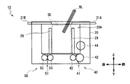
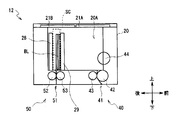
- FIG. 5 is a schematic cross-sectional view of the configuration of the customer service portion as seen from the front along the B1-B2 cross section of FIG. 4.
- FIG. 3B is a schematic cross-sectional view of the A1-A2 cross section of FIG. It is an approximate line figure showing exchange of a bill in a customer service part.
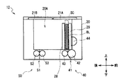
- FIG. 3B is a schematic cross-sectional view of the A1-A2 cross section of FIG. It is an approximate line figure showing exchange of a bill in a customer service part.
- the automatic teller machine 1 is configured around a box-shaped housing 2, and is installed in, for example, a financial institution or the like to perform deposit transactions and withdrawals with customers (users). Conduct transactions related to cash such as gold transactions.
- the case 2 has a shape in which a portion where it is easy to insert a bill or operate with a touch panel while the user is facing the front side, that is, a portion extending from the upper part of the front surface to the upper surface is cut off obliquely, A response portion 3 is provided at this portion.
- the reception unit 3 is provided in the front upper part of the housing 2 and directly exchanges cash, a passbook, etc. with the user, and also receives notification of transaction information and operation instructions.
- the reception unit 3 is provided with a card entry / exit 4 and a passbook entry / exit 5 so as to face the front, and a banknote deposit / withdrawal port 6, a coin deposit / withdrawal port 7 and a display operation unit 8 are provided so as to face upward. .
- Card entry / exit 4 is a portion where various cards such as cash cards are inserted or ejected.
- a card processing unit for reading account numbers and the like magnetically recorded on various cards is provided on the back side of the card slot 4.
- the bankbook entry / exit 5 is a part where the bankbook is inserted or discharged. On the back side of the bankbook entry / exit 5 is provided a bankbook processing unit for reading magnetic information recorded in the bankbook, printing transaction contents, and the like.
- the banknote deposit / withdrawal port 6 is a part where a banknote to be deposited by the user is inserted and a banknote to be dispensed to the user is discharged.
- the banknote deposit / withdrawal port 6 is opened or closed by driving a shutter described later.
- the coin deposit / withdrawal port 7 is a portion where coins to be deposited by the user are inserted and coins to be dispensed to the user are discharged. Further, the coin deposit / withdrawal port 7 is opened or closed by driving a shutter in the same manner as the bill deposit / withdrawal port 6.
- the display operation unit 8 is a touch panel in which an LCD (Liquid Crystal Display) for displaying an operation screen at the time of transaction and a touch sensor for selecting a transaction type, inputting a personal identification number, a transaction amount, and the like are integrated.
- LCD Liquid Crystal Display
- the side facing the user is the front side
- the opposite is the rear side
- the left and right sides are the left side and the right side as viewed from the user facing the front side, respectively, and the upper side and the lower side. Is defined and explained.
- a main control unit 9 that performs overall control of the entire automatic teller machine 1, a banknote depositing and dispensing machine 10 that performs various processes related to banknotes, and the like.
- the main control unit 9 is mainly configured by a CPU (Central Processing Unit) (not shown), and by reading and executing a predetermined program from a ROM, a flash memory, etc. (not shown), various transactions such as a deposit transaction and a withdrawal transaction are performed. Perform the process.
- a CPU Central Processing Unit
- ROM Read Only Memory
- flash memory etc.
- the main control unit 9 has a storage unit including a RAM (Random Access Memory), a hard disk drive, a flash memory, and the like, and stores various information in the storage unit.
- RAM Random Access Memory
- the housing 2 is constituted by a door that can be opened and closed on a part of its side such as the front side and the rear side. That is, the housing
- the housing 2 can easily perform work on each internal part by opening each door as necessary.
- the banknote depositing / dispensing machine 10 includes a plurality of parts that perform various processes related to banknotes. Each part of the bill depositing / dispensing machine 10 is controlled by the bill control unit 11.
- the banknote control unit 11 is configured around a CPU (not shown) as in the case of the main control unit 9, and determines a banknote transport destination by reading and executing a predetermined program from a ROM or flash memory (not shown). Various processing such as processing is performed.
- the banknote control part 11 has a memory
- the banknote control unit 11 is formed in the customer service unit 12 by opening a shutter after receiving a predetermined operation input via the display operation unit 8 (FIG. 1), for example, when the user performs a deposit transaction for depositing a banknote. A bill is inserted into the accumulated space SC.
- the customer service unit 12 closes the shutter, feeds the bills one by one from the accumulation space SC, and delivers them to the transport unit 13.
- the transport unit 13 is configured by a plurality of rollers, belts, and the like, and advances the banknote configured in a rectangular paper sheet shape along the short side direction and transports it to the discrimination unit 14.
- the discrimination unit 14 discriminates the denomination and authenticity of the banknote, the degree of damage, and the like using an optical element, a magnetic detection element, and the like while conveying the banknote inside the banknote control unit 11. To notify. In response to this, the banknote control unit 11 determines a transport destination of the banknote based on the acquired discrimination result.
- the transport unit 13 temporarily holds the banknote discriminated as a normal banknote in the discrimination unit 14 by, for example, transporting the banknote to the temporary storage unit 15, while holding the reject banknote identified as not to be traded. And return it to the user.
- the banknote control unit 11 allows the user to confirm the deposit amount via the display operation unit 8, transports the banknote held in the temporary storage unit 15 to the discrimination unit 14 by the transport unit 13, and denominations and damages thereof. Differentiate the degree, etc., and obtain the result of the discrimination.
- the banknote control part 11 will convey this to the rejection cassette 16 by the conveyance part 13 as a banknote which should not be reused if the degree of damage of a banknote is large, and will reuse this if the degree of damage is small. It is made to convey as a banknote which should be conveyed by the conveyance part 13, and is accommodated in the banknote cassette 17 according to the money type.
- the banknote control part 11 respond
- the banknote is fed out from the banknote cassette 17 and conveyed to the discrimination unit 14 by the conveyance unit 13.
- the banknote control unit 11 discriminates the banknotes by the discrimination unit 14, transports them to the customer service unit 12 by the transport unit 13, and accumulates them in the accumulation space SC. Open the shutter and let the user pick it up.
- the customer service unit 12 is configured to allow the user to insert banknotes into the accumulation space SC in the deposit transaction, and to collect the banknotes transported in the withdrawal transaction into the accumulation space SC and allow the user to take out. ing.
- the customer service unit 12 has a plurality of components mounted in a frame 20 that is formed in a rectangular parallelepiped shape as a whole, and an accumulation space SC for accumulating banknotes BL therein. Is forming.
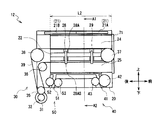
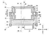
- FIG. 3A is a side view of the customer service section 12 as viewed from the left side
- FIG. 4 is a cross-sectional view of the A1-A2 cross section as viewed from the front side
- FIG. 3B is a cross section of the B1-B2 cross section as viewed from the left side. The figure is shown. For convenience of explanation, each part is simplified, and some parts are omitted or transmitted.
- the frame 20 is configured in a rectangular parallelepiped shape as a whole, and a rectangular parallelepiped internal space 20A (FIG. 3B) is formed inside.
- the inner space 20A is surrounded by the lower side portion 20B, the front side portion 20C, and the rear side portion 20D on the lower side, the front side, and the rear side, respectively, and communicates with the outside by being largely opened.
- shutters 21 ⁇ / b> A and 21 ⁇ / b> B (hereinafter collectively referred to as the shutter 21) divided into two in the front-rear direction are provided.
- the shutter 21 is slid in the front-rear direction by a driving mechanism (not shown), thereby closing the internal space 20A from the outside and opening it to the outside.
- a bill press guide 22 is provided at a height that is approximately the center of the top and bottom.
- the bill press guide part 22 is formed in a column shape elongated in the front-rear direction.
- side guides 24 and 25 are provided on the upper side and the lower side of the bill press guide unit 22, respectively.
- Side guides 24 and 25 are formed in a rectangular parallelepiped shape that is elongated in the front-rear direction, which is the stacking direction, and is slightly thin in the left-right direction. That is, the side guides 24 and 25 are both configured symmetrically. The side guides 24 and 25 form a certain gap with the bill press guide portion 22.
- a bill press guide portion 23 and side guides 26 and 27 that are configured symmetrically with the bill press guide portion 22 and side guides 24 and 25, respectively.
- the side guides 24 to 27 regulate positions in the left-right direction as the intersecting direction, that is, the width direction of the banknote in the internal space 20A (details will be described later).
- a plate-shaped bill press 28 and a pool guide 29 are provided in the internal space 20A.
- the bill press 28 as a partition plate is formed in a thin plate shape in the front-rear direction, and partitions the internal space 20A in the front-rear direction.
- the bill press arm 28 has bill press arm portions 28 ⁇ / b> A and 28 ⁇ / b> B extending outward from the upper and lower central portions on the left and right side surfaces.
- the bill press arm portion 28A is formed to be short in the vertical direction, and a slight gap is formed between each side guide 24 and 25. Further, a hole 28AH made of a round hole is formed in the vicinity of the upper and lower centers of the bill press arm 28A so as to penetrate in the front-rear direction. The bill press guide 22 is inserted through the hole 28AH.
- the bill press arm portion 28B is formed symmetrically with the bill press arm portion 28A, and the bill press guide portion 23 is inserted into the hole portion 28BH corresponding to the hole portion 28AH.
- the bill press 28 can move freely in the front-rear direction by the bill press arm portions 28A and 28B being guided by the bill press guide portions 22 and 23, respectively.
- the customer service section 12 is provided with a bill press driving section 30 as a partition plate moving section for driving the bill press 28.
- an actuator 31 is disposed on the lower side of the frame 20 on the rear side.
- the actuator 31 is provided so that the output shaft is directed in the left-right direction, and a drive gear 32 is attached to the output shaft.
- the drive gear 32 meshes with a gear 34 inserted through the shaft 33.
- the shaft 33 is formed in a long and narrow columnar shape, the central axis is disposed along the left-right direction, and a drive pulley 35 is attached to both ends thereof.
- the left and right drive pulleys 35 are located outside the side guides 24 to 27.
- an idle pulley 36 is provided on the left side surface of the frame 20 at a position almost directly above the drive pulley 35. Further, idle pulleys 37 and 38 are provided on the left side surface of the frame 20 on the left side in the vicinity of the front end and the rear end of the bill press guide portion 22, that is, outside the side guides 24 and 25.
- the mounting position of the idle pulley 37 is adjusted so that the height of the lower end portion thereof is equal to the height of the upper end of the idle pulley 36.
- the idle pulleys 36, 37 and 38 are all formed in a disk shape with the central axis directed in the left-right direction, and can rotate freely.
- a drive belt 39 is bridged between the drive pulley 35 and the idle pulleys 36, 37 and 38.
- the drive belt 39 is in contact with each pulley on the lower side of the drive pulley 35, on the rear upper side of the idle pulley 36, on the front side of the idle pulley 37, and on the rear upper side of the idle pulley 38.
- the drive belt 39 is stretched between the idle pulleys 36 and 37 substantially in parallel with the bill press guide portion 22, and the belt fixing portion 28AS of the bill press arm portion 28A is fixed at this portion.
- idle pulleys 36, 37 and 38 and a drive belt 39 are provided on the right side of the frame 20.
- the bill press drive unit 30 rotates the drive gear 32 and rotates the drive pulley 35 via the gear 34. Accordingly, the bill press drive unit 30 moves the drive belt 39 between the drive pulley 35 and the idle pulleys 36, 37, and 38, and moves the bill press 28 fixed to the drive belt 39 in the front-rear direction. Can do.
- the pool guide 29 is configured in the same plate shape as the bill press 28, and is configured to be freely movable in the front-rear direction along the bill press guide portions 22 and 23 in front of the bill press 28. .
- the pool guide 29 is moved in the front-rear direction when a driving force is transmitted from a pool guide driving unit (not shown).
- the upper and lower sides are sandwiched between the shutter 21 and the lower side portion 20B of the frame 20, and the front and rear are sandwiched between the pool guide 29 and the bill press 28. Further, a space is formed in which the left and right sides are sandwiched between the side guides 24 to 27.
- this space is referred to as an integrated space SC.
- the length in the left-right direction in the accumulation space SC is determined according to the mounting positions of the side guides 24 to 27 with respect to the frame 20.
- banknotes are stacked in the stacking space SC with the paper surface facing forward and backward and the longitudinal direction facing left and right. For this reason, the attachment positions of the side guides 24 to 27 are determined in accordance with the longest length in the longitudinal direction among the banknotes to be accommodated in the accumulation space SC.
- a feeding unit 40 that transfers the banknotes BL in the stacking space to the transport unit 13 (FIG. 2), and a stacking unit 50 that stacks the banknotes BL transported from the transport unit 13 into the stacking space. And are incorporated.
- the feeding unit 40 includes a feeding roller 42 and a driven roller 43 arranged before and after a conveyance path 41 formed along the vertical direction, and a picker roller 44 arranged on the lower side of the front side portion 20C of the frame 20. Has been.
- the conveyance path 41 is formed so as to penetrate the frame 20 up and down, and can pass the bills BL downward.
- the feeding roller 42 is opposed to the driven roller 43 with the conveying path 41 interposed therebetween, and rotates counterclockwise when viewed from the left side when a driving force is transmitted from a driving mechanism (not shown).
- the driven roller 43 is in contact with the feeding roller 42 and rotates clockwise as viewed from the left side as the feeding roller 42 rotates.
- the picker roller 44 projects a part on the rear side into the internal space 20A and, like the feeding roller 42, rotates in a counterclockwise direction when viewed from the left side when a driving force is transmitted from a driving mechanism (not shown). .
- the pool guide 29 is provided with a hole for exposing the picker roller 44 to the rear side.
- the stacking unit 50 includes a stacking roller 52 and a driven roller 53 that are disposed before and after a conveyance path 51 formed along the vertical direction.
- the conveyance path 51 is formed so as to penetrate the frame 20 up and down, and can pass the bills BL upward.
- the accumulating roller 52 is opposed to the driven roller 53 with the conveyance path 51 interposed therebetween, and rotates counterclockwise when viewed from the left side when a driving force is transmitted from a driving mechanism (not shown).
- the driven roller 53 is in contact with the stacking roller 52 and rotates in the clockwise direction when viewed from the left side as the stacking roller 52 rotates.
- the customer service unit 12 places the bill press 28 in front of the conveyance path 51 and conveys the pool guide 29 as shown in FIG. 5 when the user deposits the bill BL as a medium in a deposit transaction, for example.
- the shutter 21 is opened to allow the integrated space SC to communicate with the external space.
- the customer service unit 12 closes the shutter 21, moves the pool guide 29 to the foremost side, moves the bill press 28 forward as much as possible, and presses the bill BL against the pool guide 29. .
- the customer service unit 12 rotates the picker roller 44 of the feeding unit 40 to sequentially feed the bills BL downward, and the bills BL are sequentially moved downward along the transport path 41 by the feeding roller 42 and the driven roller 43. It is transported and delivered to the transport unit 13 (FIG. 2).
- the customer service unit 12 moves the bill press 28 to the rearmost side as shown in FIG. 7 when, for example, withdrawing the bill BL to the user in a withdrawal transaction, and moves the pool guide 29 slightly from the transport path 51.
- the integrated space SC is formed in the rear portion of the internal space 20A, positioned in front.
- the customer service unit 12 rotates the stacking roller 52 and the driven roller 53 so that the bills BL sequentially transferred from the transport unit 13 (FIG. 2) are transported upward along the transport path 51 sequentially. Accumulate in the SC.
- the customer service unit 12 gradually moves the pool guide 29 forward as the accumulated bills BL increase, and gradually expands the accumulation space SC.
- the customer service unit 12 moves the pool guide 29 and the bill press 28 forward to the positions shown in FIG. 5, and further opens the shutter 21.
- the accumulation space SC is communicated with the external space, and the bill BL is taken out by the user.
- the customer service section 12 is configured to exchange the bill BL with the user while accommodating the bill BL in the accumulation space SC whose size in the left-right direction is determined by the side guides 24 to 27.
- the engagement protrusion 24 ⁇ / b> A is formed in a rectangular parallelepiped shape that is slightly thinner than the side guide 24.
- an engaging protrusion 24B that is symmetrical with the engaging protrusion 24A protrudes rearward.
- each of the side guides 25, 26 and 27, like the side guide 24, has an engaging projection 25A, 26A and 27A protruding at the front end, and an engaging projection 25B, 26B and 27B protruding at the rear end, respectively. Has been.
- the distance L1 which is the length in the front-rear direction of the side guides 24 to 27, is substantially equal to the distance L2 (FIG. 3A) from the front surface of the rear side portion 20D to the front surface of the front side portion 20C.
- the front side portion 20C of the frame 20 is provided with insertion holes 61 and 62 penetrating in the front-rear direction.
- the insertion hole 61 is positioned in front of the side guides 24 and 25 and is formed sufficiently larger than the cross-sectional shape of the side guides 24 and 25. For this reason, the insertion hole 61 allows the side guides 24 and 25 to be inserted into the internal space 20A from the front outer side of the frame 20, respectively.
- the insertion hole 62 is located at a position in front of the side guides 26 and 27, and the side guides 26 and 27 can be inserted into the internal space 20A from the front outer side of the frame 20, respectively.
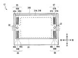
- the front side (that is, the inner surface side) of the rear side portion 20D of the frame 20 has an upper left, lower left, upper right, and lower right as positioning portions and engaged portions, respectively.
- Engagement hole groups 65, 66, 67 and 68 are provided.
- the engagement hole group 65 includes three engagement holes 65A, 65B, and 65C.
- the engagement hole 65A has a rectangular shape elongated in the vertical direction, and is slightly larger than the engagement protrusion 24B (FIG. 8) of the side guide 24.
- the engagement holes 65B and 65C are both formed in the same rectangular shape as the engagement hole 65A, and are arranged on the right side of the engagement hole 65A so as to be spaced apart from each other. That is, the engagement holes 65A, 65B, and 65C are aligned at predetermined intervals along the left-right direction.
- the side guide 24 (FIGS. 8A and 8B) is inserted into the frame 20 through the insertion hole 61, and the engagement protrusion 24B is inserted into one of the engagement holes 65A, 65B, and 65C. If it does, it will be in the state engaged with the said engaging protrusion 24B, and the rear-end side in the side guide 24 will be positioned.
- the engagement hole group 65 allows the operator to select one of the engagement holes 65A, 65B, and 65C, and then engages the engagement protrusion 24B, thereby shifting the position of the side guide 24 on the rear end side to the left and right. Can be adjusted in the direction.
- the engagement hole group 66 is configured in the same manner as the engagement hole group 65, and the three engagement holes 66A, 66B, and 66C are aligned at predetermined intervals along the left-right direction.
- the engagement hole groups 67 and 68 are formed symmetrically with the engagement hole groups 65 and 66, respectively.
- the three engagement holes 67A, 67B and 67C and the three hole portions 68A, 68B and 68C are formed. They are aligned at predetermined intervals along the left-right direction.
- the engagement hole groups 66, 67 and 68 like the engagement hole group 65, allow the operator to select one of the engagement holes and engage the engagement protrusions 25B, 26B and 27B, respectively.
- the positions of the side guides 25, 26 and 27 on the rear end side can be adjusted in the left-right direction.
- a cover plate 71 is attached to the front side of the front side portion 20C of the frame 20.
- the cover plate 71 is easily attached to or removed from the front side portion 20C of the frame 20 by a mounting screw (not shown).
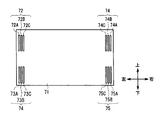
- the cover plate 71 serving as the holding switching unit and the attaching / detaching unit is positioned at the upper left, lower left, upper right, and lower right portions when attached to the front side portion 20 ⁇ / b> C of the frame 20.
- Engagement hole groups 72, 73, 74, and 75 are provided as engaging portions.
- the engagement hole group 72 includes three engagement holes 72A, 72B, and 72C, similar to the engagement hole group 65 formed in the rear side portion 20D.
- the engagement holes 72A, 72B, and 72C are each formed in an elongated rectangular shape in the vertical direction, and are slightly larger than the engagement protrusions 24A (FIGS. 8A and 8B) of the side guide 24. Further, the engagement holes 72A, 72B and 72C are aligned at a predetermined interval along the left-right direction. This interval is equal to the interval in the engagement hole group 65.
- the side guide 24 (FIG. 9) is inserted into the frame 20 through the insertion hole 61, and the engagement protrusion 24A is opposed to any one of the engagement holes 72A, 72B, and 72C.
- the cover plate 71 is attached to the front side portion 20C, the cover plate 71 is engaged with the engagement protrusion 24A, and the front end side of the side guide 24 is positioned.
- the engagement hole group 72 allows the operator to select one of the engagement holes 72A, 72B, and 72C and then engage the engagement protrusion 24A.
- the position on the front end side of the side guide 24 can be adjusted in the left-right direction.
- the engagement hole group 73 is configured in the same manner as the engagement hole group 72, and the three engagement holes 73A, 73B, and 73C are aligned at predetermined intervals along the left-right direction.
- the engagement hole groups 74 and 75 are formed symmetrically with the engagement hole groups 72 and 73, respectively.
- Three engagement holes 74A, 74B and 74C and three hole portions 75A, 75B and 75C are provided. They are aligned at predetermined intervals along the left-right direction.
- the engagement hole groups 73, 74, and 75 are engaged with the operator after selecting one of the engagement holes when the cover plate 71 is attached to the front side portion 20C, as with the engagement hole group 72.
- the positions of the side guides 25, 26, and 27 on the front end side can be adjusted in the left-right direction.
- the front and rear engagement protrusions 24B to 27B and 24A to 27A in the side guides 24 to 27 are provided at three engagement holes 65 to 68 and 72 to 75, respectively. By respectively engaging with either of these, the positions of the side guides 24 to 27 in the left-right direction can be adjusted.
- the customer service unit 12 is provided with the engagement protrusions 24A to 27A and 24B to 27B at the front ends and the rear ends of the side guides 24 to 27, respectively.
- the frame 20 of the customer service section 12 is provided with insertion holes 61 and 62 in the front side portion 20C, respectively, and three engagement holes 65A to 65C are aligned in the left-right direction on the front surface of the rear side portion 20D.
- the engaging hole groups 65 to 68 are provided.
- cover plate 71 is provided with engagement hole groups 72 to 75 each having three engagement holes 72A to 72C aligned in the left-right direction.
- the customer service unit 12 is constructed in such a manner that the bill press guide units 22 and 23 (FIGS. 3A and 3B, FIG. 4), the bill press 28, the bill press drive unit 30 and the like are assembled to the frame 20
- the side guides 24 and 25 are inserted through the insertion hole 61 of 20C, and the side guides 26 and 27 are inserted through the insertion hole 62 (FIG. 9).
- the engagement protrusions 24B to 27B provided at the rear ends of the side guides 24 to 27 correspond to the three engagement holes provided in the engagement hole groups 65 to 68, respectively, by an operator or the like.
- the bills BL are respectively engaged with the engagement holes according to the length in the longitudinal direction.
- the customer service unit 12 has a cover plate 71 attached to the front side portion 20 ⁇ / b> C of the frame 20.
- the engagement protrusions 24A to 27A provided at the front ends of the side guides 24 to 27 correspond to the three engagement holes respectively provided in the engagement hole groups 72 to 75 by the operator or the like.
- Each of the bills BL is engaged with an engagement hole that matches the length in the longitudinal direction.
- the side guide 24 is engaged with the engagement protrusions 24A and 24B after the operator selects the engagement hole 65A and the engagement hole 72A, respectively.
- the side guide 24 adjusts the space
- the service section 12 engages the engagement protrusions 24B to 27B and 24A to 27A of the side guides 24 to 27 with the engagement holes selected in the engagement hole groups 65 to 68 and 72 to 75, respectively.
- the size of the integrated space SC in the width direction can be easily changed.
- a plurality of screw holes are formed in the inner surface of the frame 20, and the side guides 24 to 27 are respectively screwed from the inner space 20A side to a desired position. There was a thing. Such a screwing operation from the inner space 20A side is a difficult operation for the operator, and the workability is poor.
- the frame guide 20 is simply attached from the outside of the frame 20 with the side guides 24 to 27 sandwiched between the frame 20 and the rear side section 20D. Since the front ends and the rear ends of the side guides 24 to 27 with respect to 20 can be positioned, the workability can be remarkably improved compared with the conventional customer service section.
- the customer service section 12 can remove the side guides 24 to 27 from the insertion holes 61 and 62 without removing the cover plate 71 from the frame 20 and performing a large disassembly work even after the manufacture. This makes it possible to change the engagement holes with which the respective engagement protrusions should be engaged.
- the side guides 24 to 27 in the inserted state can be freely moved in the left-right direction.
- the engagement protrusions 24A to 27A are simply pulled forward to such an extent that they can be removed from the respective engagement holes of the engagement hole groups 65 to 68.
- the left and right positions of the side guides 24 to 27 can be adjusted.
- the side guides 24 to 27 have a symmetrical shape, and the engagement protrusions 24A to 27A and 24B to 27B have the same shape.
- the engagement holes of the engagement hole groups 65 to 68 and the engagement holes of the engagement hole groups 72 to 75 have the same shape.
- the side guides 24 to 27 can be attached to the frame 20 even if they are reversed in the front-rear direction.
- the longitudinal direction of the side guides 24 to 27 is directed forward and backward without paying attention to the front and rear directions of the side guides 24 to 27. You just have to comply.
- the engagement protrusions 24B to 27B of the side guides 24 to 27 are given to the operator by the engagement holes selected by the engagement hole groups 65 to 68.
- the cover plate 71 is attached to the front side portion 20C of the frame 20 while the engagement protrusions 24A to 27A are engaged with the selected engagement holes of the engagement hole groups 72 to 75, respectively.
- the automatic teller machine 101 (FIG. 1) by 2nd Embodiment has the banknote depositing / withdrawing machine 110 replaced with the banknote depositing / withdrawing machine 10 compared with the automatic teller machine 1 by 1st Embodiment.
- the other parts are configured similarly.
- the banknote depositing / dispensing machine 110 (FIG. 2) is different from the banknote depositing / dispensing machine 10 in the first embodiment in that the banknote depositing / dispensing machine 110 has a customer service part 112 instead of the customer service part 12, but the other parts are the same. It is configured.
- the customer service unit 112 is configured around a frame 120 that replaces the frame 20, and side guides 124 and 125 that replace the side guides 24, 25, 26, and 27. 126 and 127, and the cover plate 71 is omitted.
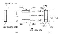
- the side guide 124 has an engagement protrusion 124B corresponding to the engagement protrusion 24B at the rear end portion, and is greatly different from the engagement protrusion 24A at the front end portion.
- An engaging portion 124A is formed.
- the side guide 124 is made of a predetermined resin material.
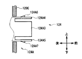
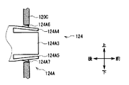
- the engaging portion 124A includes a central portion 124A3 at the center, a plate portion 124A4 at the upper end, and a plate portion at the lower end by grooves 124A1 and 124A2 formed deeply from the front end side toward the rear in the vicinity of the upper end and in the vicinity of the lower end. 124A5.
- Each of the plate-like portions 124A4 and 124A5 is formed in a plate shape that is thin in the vertical direction and long in the front-rear direction, and is connected to the main body portion of the side guide 124 at the rear end portion, and further has a space formed in the vertical direction. Yes. Therefore, the plate-like portions 124A4 and 124A5 are elastically deformed when an external force in the vertical direction is applied.
- a claw portion 124A6 is erected at a position away from the front end of the upper surface of the plate-like portion 124A4 by a predetermined distance.
- the claw portion 124A6 has an inclined surface facing obliquely upward on the rear side, and a vertical surface facing substantially frontward on the front side.
- a claw portion 124A7 formed substantially symmetrically with the claw portion 124A6 is erected downward at a position away from the front end on the lower surface of the plate-like portion 124A5 by a predetermined distance.
- the side guides 125, 126, and 127 are all configured in the same manner as the side guide 124, and have engaging portions 125A, 126A, and 127A configured similarly to the engaging portion 124A, respectively.
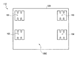
- the frame 120 is provided with insertion holes 161, 162, 163, and 164 in place of the insertion holes 61 and 62 in the front side part 120C corresponding to the front side part 20C.
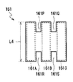
- the insertion hole 161 has a shape in which three regions 161 ⁇ / b> A, 161 ⁇ / b> B, and 161 ⁇ / b> C elongated vertically are connected in the left-right direction.
- the regions 161A, 161B, and 161C are partitioned from each other by partition portions 161P and 161Q that project downward from the upper side of the insertion hole 161 and partition portions 161R and 161S that project upward from the lower side. Yes.
- the regions 161A, 161B, and 161C are formed to be equal to or slightly larger than the projected shape ((2) in FIG. 12) when the side guide 124 is viewed from the front.
- the vertical length L4 of the insertion hole 161 is slightly larger (longer) than the vertical length L3 of the main body portion of the side guide 124 (FIG. 12).
- the length L4 is smaller (shorter) than the length L5 from the upper end of the claw portion 124A6 to the lower end of the claw portion 124A7 in the side guide 124.
- the insertion holes 162, 163, and 164 are all configured in the same manner as the insertion hole 161.
- the engagement portions 124A to 127A are formed in the side guides 124 to 127, and the insertion holes 161 to 164 are provided in the front side portion 120C.
- the customer service portion 112 is formed with insertion holes 161 to 164 having a plurality of regions partitioned from each other in the front side portion 120C of the frame 120 (FIGS. 13 and 14). .
- side guides 124 to 127 are provided with engagement protrusions 124B to 127B similar to those of the first embodiment at the rear end, and engagement portions 124A to 127A are provided at the front end, respectively.
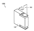
- the side guide 124 is inserted from the front of the frame 120 through the insertion hole 161 of the front side portion 120C.
- the side guide 124 is inserted into the region 161A after any one of the regions 161A to 161C of the insertion hole 161 is selected (for example, the region 161A).
- the side guide 124 is inserted into the region 161A (FIG. 14)
- the position in the vertical direction is restricted by the upper side and the lower side of the insertion hole 161
- the position in the left and right direction is restricted by the partition parts 161P and 161R. Therefore, the insertion location in the insertion hole 161 is fixed to the region 161A.
- the side guide 124 is only inserted through the selected region of the insertion hole 161, and the front mounting position is temporarily fixed.
- the side guides 124 are sequentially inserted into the frame 120, so that the engaging portion 124A reaches the vicinity of the front side portion 120C as shown in the sectional view of FIG. 16A.
- the engagement protrusion 124B (FIG. 12) on the rear end side is inserted into the engagement hole 65A (FIG. 10) of the engagement hole group 65, as in the first embodiment.
- the claw portions 124A6 and 124A7 are positioned on the rear surface side of the front side portion 120C as shown in FIG. 16C.
- the plate-like portions 124A4 and 124A5 return to the natural state by the action of the elastic force because the claw portions 124A6 and 124A7 do not contact the inner surface of the insertion hole 161 in the front side portion 120C.
- the claw portion 124A6 protrudes above the upper side of the insertion hole 161 in the front side portion 120C, and the claw portion 124A7 protrudes below the lower side of the insertion hole 161 in the front side portion 120C.
- the side guide 124 is engaged with the claw portions 124A6 and 124A7 on the rear surface side of the front side portion 120C and is attached to the frame 120.
- the side guide 124 is inserted into the frame 120 so as to pass through the region 161A of the insertion hole 161 and engages the engagement protrusion 124B by the engagement between the engagement portion 124A and the front side portion 120C.
- the state engaged with the hole 65 ⁇ / b> A can be maintained, and does not naturally come out of the frame 120 forward.
- the side guide 124 is pulled forward while the plate-like portions 124A4 and 124A5 are elastically deformed, and thus the engaging portion 124A is positioned in front of the front side portion 120C through the state shown in FIG. 16B. (FIG. 16A).
- the engagement protrusion 124B is extracted from the engagement hole 65A.
- the side guide 124 is finally pulled out from the insertion hole 161 by being pulled forward, and is completely removed from the frame 120.
- the engagement protrusions 125B to 127B are connected to the engagement hole groups 66 to 68, respectively.
- the engaging portions 125A to 127A can be engaged with the front side portion 120C while being engaged with the joint hole, and the attached state can be maintained.
- the side guides 125 to 127 are pulled out forward by disengaging the engaging portions 125A to 127A and the front side portion 120C in a state where they are attached to the frame 120. 120 can be easily removed.
- the customer service section 112 allows the operator to insert the side guides 124 to 127 into the selected regions of the insertion holes 161 to 164 and to engage the side guides 124 to 127 with the selected engagement holes of the engagement hole groups 65 to 68.
- the positions of the side guides 124 to 127 in the left-right direction can be easily adjusted by simply engaging the mating protrusions 124B to 127A.
- the customer service unit 112 can engage the engagement portion 124A and the like with the front side portion 120C of the frame 120 only by inserting the side guide 124 and the like to the farthest rear.
- the plate-like sections 124A4 and B5 of the engagement section 124A are elastically deformed so as to be close to each other in the vertical direction, and the engagement is performed simply by pulling forward. It can be released and removed from the frame 120.
- the removal work can be greatly facilitated as compared with the case where the side guide 24 is pulled out after removing the cover plate 71 as in the first embodiment.
- the customer service unit 112 makes adjustment to a desired mounting position extremely easily and quickly without causing an operator to remove or install other parts or using a tool or the like. Work can be done.
- customer service unit 112 can achieve the same operational effects as the first embodiment in other respects.
- the service portion 112 allows the side guides 124 to 127 to be inserted from the front of the frame 120 through the selected regions of the insertion holes 161 to 164 in the front side portion 120C.
- the engaging protrusions 124B to 127B are engaged with the engaging holes of the engaging hole groups 65 to 68, respectively, and the engaging portions 124A to 127A are engaged with the front side portion 120C.
- the customer service section 112 can be attached to the frame 120 with the front end portions and rear end portions of the side guides 124 to 127 adjusted to desired positions, and can be maintained in this state, and the engagement portions 124A to 124A can be maintained. It is possible to easily remove 127A by simply disengaging the front side portion 120C.
- the automatic teller machine 201 (FIG. 1) according to the third embodiment has a banknote depositing / dispensing machine 210 that replaces the banknote depositing / dispensing machine 10 as compared with the automatic teller machine 1 according to the first embodiment.
- the other parts are configured similarly.
- the banknote depositing / dispensing machine 210 (FIG. 2) is different from the banknote depositing / dispensing machine 10 in the first embodiment in that it has a banknote cassette 217 instead of the banknote cassette 17, but the customer service section 12 and the like. This part is configured similarly.
- the banknote cassette 217 is functionally similar to the customer service unit 12 in the first embodiment in that the banknotes BL are accumulated and accommodated therein, and partly similar to the customer service unit 12 in the configuration, The customer service section 12 is inverted.
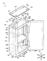
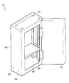
- the bill cassette 217 is configured around a frame 220 corresponding to the frame 20 as shown in FIG.
- the frame 220 is formed in a rectangular parallelepiped shape, and is closed in the vertical direction, the horizontal direction, and the rear direction, and communicates with the outside by largely opening the front surface.
- a door 221 is attached to the front of the frame 220 through a hinge 221A so as to be opened and closed.
- stage guide portions 222 and 223 corresponding to the bill press guide portions 22 and 23 are provided at positions substantially in the front and rear.
- the stage guides 222 and 223 are both formed in a column shape elongated in the vertical direction.
- Side guides 224 and 225 respectively corresponding to the side guides 24 and 25 are provided on the front side and the rear side of the stage guide unit 222, respectively.
- side guides 226 and 227 respectively corresponding to the side guides 26 and 27 are provided on the front side and the rear side of the stage guide unit 223, respectively.
- the side guides 224 to 227 are configured in a rectangular parallelepiped shape that is elongated in the vertical direction, and regulate the position of the bill BL in the left-right direction in the internal space 220A, like the side guides 24 to 27.
- the side guide 224 is provided with engagement protrusions 224A and 224B at the upper end and the lower end similarly to the engagement protrusions 24A and 24B (FIGS. 8A and B) of the side guide 24. Further, the side guides 225 to 227 are provided with engaging protrusions 225A to 227A and 225B to 227B at the lower end and the upper end, respectively.
- a stage 228 corresponding to the bill press 28 is provided in the internal space 220A.
- the stage 228 is formed in a thin plate shape in the vertical direction, and partitions the internal space 220A in the vertical direction.
- Stage arm portions are extended outward on the left and right side surfaces of the stage 228, respectively.
- the stage arm part is formed with a hole penetrating vertically, and stage guide parts 222 and 223 are inserted into the hole part, respectively.
- the stage 228 is driven by a stage drive unit 230 corresponding to the bill press drive unit 30.
- Some components constituting the stage driving unit 230 are arranged on the left side of the side guides 224 and 225 and on the right side of the side guides 226 and 227, respectively.
- the upper and lower sides are sandwiched between the upper portion 220C of the frame 220 and the stage 228, the front and rear portions are sandwiched between the rear side portion 220B of the frame 220 and the door 221, and the left and right portions are sandwiched between the side guides 224 to 227.
- the sandwiched space is defined as an integrated space SC.
- the upper portion 220C of the frame 220 is provided with a loading / unloading portion 240 that exchanges bills BL with the transport portion 13 (FIG. 2).
- the entry / exit section 240 appropriately rotates and drives a roller (not shown) to take in the bill BL into the internal space 220A through the slit 241 formed in the upper portion 220C, or to feed the bill BL out of the internal space 220A. It passes to the transport unit 13 through the slit 241.
- insertion holes 261 and 262 corresponding to the insertion holes 61 and 62, respectively, are formed on the left and right, respectively.
- the insertion hole 261 penetrates the upper portion 220C in the vertical direction, and the side guides 224 and 225 can be inserted into the internal space 220A from above the frame 220, respectively.
- the insertion hole 262 passes through the upper portion 220C in the vertical direction, and allows the side guides 226 and 227 to be inserted into the internal space 220A from above the frame 220, respectively.
- the engagement corresponding to the engagement hole groups 65, 66, 67, and 68 (FIG. 10) on the left front, left rear, right front, and right rear, respectively.
- Hole groups 265, 266, 267 and 268 are provided.
- the engagement hole groups 265 to 268 are constituted by three engagement holes arranged in the left-right direction, like the engagement hole groups 65 to 68, respectively.
- the positions on the lower end side of 224 to 227 can be adjusted in the left-right direction.
- a cover plate 271 corresponding to the cover plate 71 is attached to the upper surface side of the upper portion 220C in the frame 220.
- the cover plate 271 is provided with engagement hole groups 272, 273, 274, and 275 corresponding to the engagement hole groups 72, 73, 74, and 75, respectively.
- the engagement hole groups 272 to 275 are constituted by three engagement holes arranged in the left-right direction, like the engagement hole groups 72 to 75, respectively.
- the engagement hole groups 272 to 275 are similar to the engagement hole groups 72 to 75 in that, when the cover plate 271 is attached to the upper portion 220C, the engagement protrusions are selected after selecting one of the engagement holes.
- the positions of the side guides 224 to 227 on the upper end side can be adjusted in the left-right direction.
- a slit 276 for allowing the bill BL to pass is formed at a position corresponding to the slit 241 of the input / output unit 240.
- the upper and lower engagement protrusions 224B to 227B and 224A to 227A in the side guides 224 to 227 are provided at three engagement holes in the engagement hole groups 265 to 268 and 272 to 275, respectively. By respectively engaging with either of these, the positions of the side guides 224 to 227 in the left-right direction can be adjusted.
- the banknote cassette 217 according to the third embodiment is provided with the engaging protrusions 224A to 227A and 224B to 227B on the upper and lower ends of the side guides 224 to 227, respectively.
- the frame 220 of the banknote cassette 217 is provided with insertion holes 261 and 262 in the upper part 220C, respectively, and three engagement holes 65A to 65C are aligned in the left-right direction on the upper surface of the lower part 220D.
- the engaging hole groups 65 to 68 are provided.
- cover plate 71 is provided with engagement hole groups 72 to 75 each having three engagement holes 72A to 72C aligned in the left-right direction.
- the side guides 224 and 225 are inserted into the insertion hole 261 of the upper part 220C in a state where the stage guides 222 and 223, the stage 228, the stage drive unit 230, and the like are assembled to the frame 220 in the manufacturing process.
- the side guides 226 and 227 are inserted through the insertion hole 262.
- the engagement protrusions 224B to 227B provided at the lower ends of the side guides 224 to 227 correspond to the corresponding one of the three engagement holes provided to the engagement hole groups 265 to 268 by the operator or the like.
- Each of the bills BL is engaged with an engagement hole that matches the length in the longitudinal direction.
- the bill cassette 217 has a cover plate 271 attached to the upper portion 220 ⁇ / b> C of the frame 220.
- the engagement protrusions 224A to 227A provided at the upper ends of the side guides 224 to 227 correspond to the corresponding one of the three engagement holes provided to the engagement hole groups 272 to 275 by the operator or the like.
- Each of the bills BL is engaged with an engagement hole that matches the length in the longitudinal direction.
- the length of the side guides 224 to 227 in the left-right direction in the accumulation space SC can be adjusted to be slightly longer than the longest length of the bills BL to be handled.
- the banknote cassette 217 is engaged with the engagement of the side guides 224 to 227 in the selected engagement holes of the engagement hole groups 265 to 268 and 272 to 275 in the manufacturing process, as in the first embodiment.
- the lateral positions of the side guides 224 to 227 can be easily adjusted.
- the side guide can be easily removed by simply removing the cover plate 271 from the upper portion 220C of the frame 220.
- the engagement state between the engagement protrusions 224 to 227 and the engagement holes of the engagement hole groups can be released, and the attachment position can be changed immediately.
- the bill cassette 217 can achieve the same effects as the customer service unit 12 according to the first embodiment in other respects.
- the engaging protrusions 224B to 227B of the side guides 224 to 227 are provided to the operator by the engaging holes selected by the engaging hole groups 265 to 268.
- the cover plate 271 is attached to the upper portion 220C of the frame 220 while the engagement protrusions 224A to 227A are engaged with the selected engagement holes of the engagement hole groups 272 to 275, respectively.
- the banknote cassette 217 can be easily adjusted from the outside of the frame 220 to easily attach the side guides 224 to 227 even after the assembling.
- an engagement hole is formed in each of the rear end portions of the side guides 24 to 27, and a plurality of engagement protrusions are erected on the rear side portion 20D.
- the positions of the rear end portions of the side guides 24 to 27 with respect to the frame 20 may be fixed by engaging various shapes that are engaged with each other, such as engaging the engagement protrusions with each other. .
- the front end portions of the side guides 24 to 27 are fixed when the cover plate 71 is attached to the frame 20, and the side guide 24 is removed when the cover plate 71 is removed from the frame 20.
- the case where the fixing of the front end portions of .about.27 is released has been described.
- the embodiment is not limited thereto, and for example, the cover plate 71 may be attached to the front side of the front side portion 20C of the frame 20 via a hinge at the lower end thereof.
- the cover plate 71 is locked in a state in which the cover plate 71 is in contact with the front side portion 20C by a predetermined lock member, and the front end portions of the side guides 24 to 27 are fixed, or the lock is released and the cover plate 71 is rotated.
- the front end portions of the side guides 24 to 27 may be released by moving them.
- the side guides 24 to 27 are symmetrically shaped, and the engagement protrusions 24A to 27A and 24B to 27B are shaped to be equivalent to each other.
- the case where the 68 engaging holes and the engaging holes of the engaging hole groups 72 to 75 have the same shape has been described.
- the embodiment is not limited to this.
- the side guides 24 to 27 have asymmetrical front and rear shapes, and the engagement protrusions 24A to 27A and 24B to 27B have different shapes, and the engagement hole groups 65 to 68 have different shapes.
- the engagement holes and the engagement holes of the engagement hole groups 72 to 75 may have different shapes.
- the embodiment is not limited to this.
- the side guides 24 and 25 may have different vertical lengths.
- the side corners (ridge lines) that contact the bills BL are chamfered or rounded.
- Various shapes may be used. The same applies to the second and third embodiments.
- claw portions 124A6 and 124A7 are provided on the plate-like portions 124A4 and 124A5 that are elastically deformed in the engaging portion 124A and the like of the side guide 124, respectively, and these are engaged with the front side portion 120C. The case where it was made to let it be described.
- a plate-like portion and a claw portion are formed on the front side portion 120C, and the side guide 124 and the like are formed by various methods such as engaging the claw portion with the side guide 124 and the like. And the front side portion 120C may be engaged with each other.
- engagement projections 124B to 127A similar to those of the first embodiment are formed on the rear end portions of the side guides 124 to 127, respectively, and these are formed on the rear side portion of the frame 120.
- the case where the engagement holes 65 to 68 formed in 120D are engaged has been described.
- the embodiment is not limited to this.
- the rear end portion of the side guides 124 to 127 is provided with an engaging portion having the same configuration as the front end portion, and the rear side portion 120D of the frame 120 is similar to the front side portion 120C.
- An insertion hole having a shape may be formed.
- the side guides 124 to 127 can be inserted or pulled out from either the front or the rear of the frame 120.
- the bill press guide portions 22 and 23 are provided at approximately the center of the upper and lower ends at both the left and right ends in the frame 20, and the sides are arranged on the upper and lower sides, that is, two on the left and right sides.
- the case where the guides 24 and 25 and 26 and 27 are attached has been described.
- the embodiment is not limited to this.
- the bill press guide portions 22 and 23 are provided near the lower ends of the left and right ends in the frame 20, and the side guides are respectively provided on the upper side, that is, one on the left and right. You may make it attach.
- An arbitrary number of side guides may be attached to the left and right at positions where the position can be regulated. The same applies to the second and third embodiments.
- the embodiment is not limited to this, and the number of engagement holes provided in the engagement hole groups 65 to 68 and 72 to 75 may be 2 or 4 or more. Further, the number of engagement holes may be different for each engagement hole group. Furthermore, the alignment direction of the engagement holes is not limited to the left-right direction, and may be, for example, an oblique direction. The same applies to the second and third embodiments.
- two insertion holes 61 and 62 are formed in the front side portion 20C, the side guides 24 and 25 are inserted into the insertion hole 61, and the side guide 26 and The case where 27 is inserted is described.
- the embodiment is not limited to this.
- the front side portion 20C may be provided with four insertion holes corresponding to the side guides 24 to 27, or twelve insertion holes corresponding to the respective engagement holes. You may make it drill a hole, respectively. The same applies to the third embodiment.
- the embodiment is not limited to this, and may be applied to other parts provided in the banknote depositing / dispensing machine 10, such as the reject cassette 16 (FIG. 2).
- the bill press or stage is moved along the stacking direction of the bills BL in the space formed inside, and the bills BL are put in the stacking space SC partitioned by the bill press or stage. Any location that can be accumulated is acceptable.
- the present invention is not limited to this.
- various apparatuses that handle banknotes BL such as banknote processing apparatuses (so-called teller machines) used for counter staff at counters of financial institutions, etc. You may do it.
- the present invention may be applied to a place where various media such as securities and cash vouchers are accumulated. The same applies to the second and third embodiments.
- the embodiment is not limited to this, and the medium accommodating device is configured by a frame having various other configurations, a partition plate, a partition plate moving unit, a side guide, a positioning unit, and a holding switching unit. May be.
- the bill press driving unit 30, side guides 24 to 27 as side guides, engagement hole groups 65 to 68 and 72 to 75 as positioning units, and a cover plate 71 as a holding switching unit constitute a medium processing apparatus. The case where the automatic teller machine 1 is configured was described.
- the embodiment is not limited to this, and the medium processing apparatus is configured by a transport unit, a frame, a partition plate, a partition plate moving unit, a side guide, a positioning unit, and a holding switching unit having various other configurations. You may make it comprise.
- the present embodiment can also be used in various apparatuses that accumulate various media in an internal accumulation space.
Landscapes
- Engineering & Computer Science (AREA)
- Mechanical Engineering (AREA)
- Physics & Mathematics (AREA)
- General Physics & Mathematics (AREA)
- Pile Receivers (AREA)
- Sheets, Magazines, And Separation Thereof (AREA)
- Feeding And Guiding Record Carriers (AREA)
- Packaging Of Annular Or Rod-Shaped Articles, Wearing Apparel, Cassettes, Or The Like (AREA)
Abstract
Description
本発明は媒体収容装置及び媒体処理装置に関し、例えば紙幣等の媒体を投入して所望の取引を行う現金自動預払機(ATM)等に適用できるものである。
[1-1.現金自動預払機の全体構成]
図1に外観を示すように、現金自動預払機1は、箱状の筐体2を中心に構成されており、例えば金融機関等に設置され、顧客(ユーザ)との間で入金取引や出金取引等の現金に関する取引を行う。
次に、接客部12の構成について説明する。図3A及びB並びに図4に示すように、接客部12は、全体として直方体状に構成されたフレーム20内に複数の部品が取り付けられており、内部に紙幣BLを集積するための集積空間SCを形成している。
次に、接客部12におけるフレーム20に対するサイドガイド24~27(図3A及びB、図4)の取付について説明する。
以上の構成において、第1の実施の形態による接客部12には、サイドガイド24~27の前端及び後端に、係合突起24A~27A及び24B~27Bをそれぞれ設けた。
第2の実施の形態による現金自動預払機101(図1)は、第1の実施の形態による現金自動預払機1と比較して、紙幣入出金機10に代わる紙幣入出金機110を有する点が相違するものの、他の部分については同様に構成されている。
接客部112は、第1の実施の形態による接客部12と比較して、フレーム20に代わるフレーム120を中心に構成されており、サイドガイド24、25、26及び27に代わるサイドガイド124、125、126及び127を有すると共に、カバー板71が省略されている点が相違している。
以上の構成において、第2の実施の形態による接客部112には、フレーム120の前側部120Cに、互いに仕切られた複数の領域を有する挿通孔161~164を形成した(図13、図14)。
第3の実施の形態による現金自動預払機201(図1)は、第1の実施の形態による現金自動預払機1と比較して、紙幣入出金機10に代わる紙幣入出金機210を有する点が相違するものの、他の部分については同様に構成されている。
紙幣カセット217は、内部に紙幣BLを集積して収容する点において、第1の実施の形態における接客部12と機能的に類似しており、その構成においても接客部12と一部類似し、当該接客部12を倒立させたような形状となっている。
以上の構成において、第3の実施の形態による紙幣カセット217には、サイドガイド224~227の上端及び下端に、係合突起224A~227A及び224B~227Bをそれぞれ設けた。
なお上述した第1の実施の形態においては、サイドガイド24~27の後側端部にそれぞれ設けた係合突起24A~27Aとフレーム20の後側部20Dに形成した係合孔群65~68の各係合孔とを係合させることにより、フレーム20に対するサイドガイド24~27の後側端部の位置を固定する場合について述べた。
Claims (8)
- 媒体を収容する内部空間を内部に有するフレームと、
前記内部空間を所定の集積方向と交差するように仕切り、前記媒体が前記集積方向に沿って集積される集積空間を形成する仕切板と、
前記フレームに対し前記仕切板を前記集積方向に沿って移動させる仕切板移動部と、
前記フレーム内における前記仕切板の移動範囲及び前記仕切板移動部との干渉を回避する箇所に取り付けられ、前記集積方向と交差する交差方向に関し前記集積空間の大きさを規定するサイドガイドと、
前記フレームの前記集積方向に関する端部に設けられ、前記サイドガイドの端部を複数の取付位置から選択された一の取付位置に位置決めする位置決め部と、
前記サイドガイドの端部が位置決めされた保持状態と位置決めされていない保持解除状態とを切り替える保持切替部と
を具える媒体収容装置。 - 前記フレームの端部に設けられ、前記内部空間と外部との間で前記サイドガイドを挿通させる挿通孔
をさらに具え
前記保持切替部は、
前記フレームの端部に装着されたときに前記挿通孔の少なくとも一部を閉塞して前記保持状態となり、前記フレームの端部から離脱されたときに前記挿通孔を開放して前記保持解除状態となる着脱部である
請求項1に記載の媒体収容装置。 - 前記位置決め部は、
前記複数の取付位置に応じて前記着脱部にそれぞれ形成された複数の被係合部であり、
前記サイドガイドは、
前記複数の被係合部のいずれかと係合することにより位置決めされる係合部が端部に設けられている
請求項2に記載の媒体収容装置。 - 前記フレームの前記挿通孔が設けられた端部と反対側の反対端部に設けられ、前記サイドガイドの前記反対側の端部を複数の取付位置から選択された一の取付位置に位置決めし、前記位置決め部と同等形状の複数の被係合部でなる反対側位置決め部
をさらに具え、
前記サイドガイドは、
前記集積方向に関し対称形状でなり、前記係合部と同等の形状でなる反対側係合部が前記反対側の端部に設けられている
請求項3に記載の媒体収容装置。 - 前記位置決め部は、
前記複数の取付位置に応じて、前記フレーム又は前記フレームに取り付けられる部品にそれぞれ形成された複数の孔部であり、
前記サイドガイドは、
前記孔部に挿入されることにより位置決めされる突起が端部に形成されている
請求項1に記載の媒体収容装置。 - 前記フレームの端部に設けられ、前記内部空間と外部との間で前記サイドガイドを挿通させる挿通孔
をさらに具え、
前記位置決め部は、
前記フレームの端部における前記挿通孔の周囲部分でなり、前記交差方向に関する前記サイドガイドの位置を定める
請求項1に記載の媒体収容装置。 - 前記保持切替部は、
前記サイドガイドの端部に設けられ、前記位置決め部に対して係合したときに前記保持状態となり、その係合を解除したときに前記保持解除状態となる
請求項6に記載の媒体収容装置。 - 請求項1に記載の媒体収容装置と、
媒体を搬送する搬送部と、
を具え、
前記フレームは、前記搬送部により搬送されてきた前記媒体又は前記搬送部により搬送すべき前記媒体を内部空間に収容する媒体処理装置。
Priority Applications (4)
| Application Number | Priority Date | Filing Date | Title |
|---|---|---|---|
| RU2015129113A RU2608267C1 (ru) | 2013-01-23 | 2013-11-08 | Устройство размещения носителей и устройство обработки носителей |
| US14/761,919 US9858743B2 (en) | 2013-01-23 | 2013-11-08 | Medium housing device and medium processing device |
| CN201380070151.8A CN104919501B (zh) | 2013-01-23 | 2013-11-08 | 介质容纳装置和介质处理装置 |
| BR112015017127A BR112015017127A2 (pt) | 2013-01-23 | 2013-11-08 | dispositivo de alojamento de meio e dispositivo de processamento de meio |
Applications Claiming Priority (2)
| Application Number | Priority Date | Filing Date | Title |
|---|---|---|---|
| JP2013010346A JP6119265B2 (ja) | 2013-01-23 | 2013-01-23 | 媒体収容装置及び媒体処理装置 |
| JP2013-010346 | 2013-01-23 |
Publications (1)
| Publication Number | Publication Date |
|---|---|
| WO2014115398A1 true WO2014115398A1 (ja) | 2014-07-31 |
Family
ID=51227202
Family Applications (1)
| Application Number | Title | Priority Date | Filing Date |
|---|---|---|---|
| PCT/JP2013/080319 Ceased WO2014115398A1 (ja) | 2013-01-23 | 2013-11-08 | 媒体収容装置及び媒体処理装置 |
Country Status (6)
| Country | Link |
|---|---|
| US (1) | US9858743B2 (ja) |
| JP (1) | JP6119265B2 (ja) |
| CN (1) | CN104919501B (ja) |
| BR (1) | BR112015017127A2 (ja) |
| RU (1) | RU2608267C1 (ja) |
| WO (1) | WO2014115398A1 (ja) |
Cited By (3)
| Publication number | Priority date | Publication date | Assignee | Title |
|---|---|---|---|---|
| CN106663349A (zh) * | 2014-10-22 | 2017-05-10 | 冲电气工业株式会社 | 介质收纳装置和介质交易装置 |
| CN107438869A (zh) * | 2017-06-05 | 2017-12-05 | 深圳怡化电脑股份有限公司 | 收纳箱定位机构及金融设备 |
| CN108053549A (zh) * | 2018-02-02 | 2018-05-18 | 深圳怡化电脑股份有限公司 | 一种接客装置及金融自助终端 |
Families Citing this family (9)
| Publication number | Priority date | Publication date | Assignee | Title |
|---|---|---|---|---|
| CN104103125B (zh) * | 2014-08-08 | 2017-03-22 | 广州广电运通金融电子股份有限公司 | 钞箱及其纸币尺寸调节装置 |
| JP6459756B2 (ja) * | 2015-04-28 | 2019-01-30 | 沖電気工業株式会社 | 媒体収納装置及び媒体取引装置 |
| KR20170043190A (ko) * | 2015-10-13 | 2017-04-21 | 노틸러스효성 주식회사 | 매체 처리 장치 및 매체 처리 방법 |
| CN105354917B (zh) * | 2015-11-27 | 2018-10-19 | 深圳怡化电脑股份有限公司 | 金融自助设备的存取钞机构 |
| JP6763212B2 (ja) * | 2016-06-28 | 2020-09-30 | 沖電気工業株式会社 | 媒体集積装置及び媒体処理装置 |
| TWI601681B (zh) * | 2017-02-17 | 2017-10-11 | 鴻發國際科技股份有限公司 | 文件儲存組件 |
| JP6888394B2 (ja) * | 2017-04-24 | 2021-06-16 | 沖電気工業株式会社 | 媒体収納庫及び媒体取引装置 |
| JP6926905B2 (ja) * | 2017-09-28 | 2021-08-25 | 沖電気工業株式会社 | 媒体収納庫及び自動取引装置 |
| JP7327112B2 (ja) * | 2019-11-26 | 2023-08-16 | 沖電気工業株式会社 | 媒体処理装置及び自動取引装置 |
Citations (2)
| Publication number | Priority date | Publication date | Assignee | Title |
|---|---|---|---|---|
| JPH0712346U (ja) * | 1993-06-16 | 1995-02-28 | 沖電気工業株式会社 | 用紙カセット |
| JP2006127050A (ja) * | 2004-10-27 | 2006-05-18 | Oki Electric Ind Co Ltd | 紙幣入出金装置 |
Family Cites Families (20)
| Publication number | Priority date | Publication date | Assignee | Title |
|---|---|---|---|---|
| US3087771A (en) * | 1960-10-19 | 1963-04-30 | Jack M Pari | Adjustable drawer and shelf slide mounting assembly |
| US4022459A (en) * | 1974-07-24 | 1977-05-10 | Mather Richard A | Envelope stacker |
| US4494743A (en) * | 1981-08-31 | 1985-01-22 | Docutel Corporation | Dispenser picker apparatus |
| US4529119A (en) * | 1983-08-12 | 1985-07-16 | Ncr Corporation | Tampering-proof cassette used in a cash dispenser |
| US4593895A (en) * | 1984-04-06 | 1986-06-10 | Ncr Corporation | Automatically adjusting currency pusher plate apparatus |
| JP3168127B2 (ja) * | 1993-11-24 | 2001-05-21 | キヤノン株式会社 | シート積載装置及び画像形成装置 |
| US5624017A (en) * | 1994-04-06 | 1997-04-29 | Gap Technologies, Inc. | Multi-purpose currency validator with compact low power cassette stacker |
| DE10261995B4 (de) * | 2002-01-27 | 2005-11-24 | Kendro Laboratory Products Gmbh | Objekt-Lagervorrichtung |
| JP4294572B2 (ja) * | 2004-03-05 | 2009-07-15 | 株式会社リコー | 給紙カセット、記録媒体サイズ検知装置及び画像形成装置 |
| SE528945C8 (sv) * | 2004-07-06 | 2007-10-09 | Scan Coin Ind Ab | Kontantåteranvändningssystem innefattande en kontantmottagningsenhet och en kontantutdelningsenhet |
| KR100627557B1 (ko) * | 2004-12-24 | 2006-09-21 | 노틸러스효성 주식회사 | 지폐류 출금기용 카세트 |
| KR100754050B1 (ko) | 2006-06-30 | 2007-08-31 | 노틸러스효성 주식회사 | 금융자동화기기의 지폐가이드장치 |
| US20100052237A1 (en) * | 2006-10-18 | 2010-03-04 | Lars Karoly Herczeg | Document handling apparatus |
| JPWO2009031237A1 (ja) * | 2007-09-07 | 2010-12-09 | グローリー株式会社 | 貨幣収納カセット及び貨幣処理装置 |
| US8733634B1 (en) * | 2008-06-27 | 2014-05-27 | Diebold Self-Service Systems, Division Of Diebold, Incorporated | Banking system controlled responsive to data bearing records |
| IT1398095B1 (it) * | 2010-02-12 | 2013-02-07 | Francom Spa | Cassettiera per furgoni e metodo per il suo montaggio. |
| US7886888B1 (en) * | 2010-02-22 | 2011-02-15 | International Currency Technologies Corporation | Bill box, bill acceptor assembly with bill box |
| JP5218515B2 (ja) | 2010-10-06 | 2013-06-26 | 沖電気工業株式会社 | 紙葉類集積繰出し機構 |
| US9353546B2 (en) * | 2010-10-15 | 2016-05-31 | José Guadalupe Garza Montemayor | Snap locking coupling system for pieces or coupling members |
| KR101514390B1 (ko) * | 2011-07-26 | 2015-04-22 | 히타치 오므론 터미널 솔루션즈 가부시키가이샤 | 지엽류 처리 장치 |
-
2013
- 2013-01-23 JP JP2013010346A patent/JP6119265B2/ja not_active Expired - Fee Related
- 2013-11-08 WO PCT/JP2013/080319 patent/WO2014115398A1/ja not_active Ceased
- 2013-11-08 BR BR112015017127A patent/BR112015017127A2/pt not_active IP Right Cessation
- 2013-11-08 RU RU2015129113A patent/RU2608267C1/ru active
- 2013-11-08 US US14/761,919 patent/US9858743B2/en not_active Expired - Fee Related
- 2013-11-08 CN CN201380070151.8A patent/CN104919501B/zh not_active Expired - Fee Related
Patent Citations (2)
| Publication number | Priority date | Publication date | Assignee | Title |
|---|---|---|---|---|
| JPH0712346U (ja) * | 1993-06-16 | 1995-02-28 | 沖電気工業株式会社 | 用紙カセット |
| JP2006127050A (ja) * | 2004-10-27 | 2006-05-18 | Oki Electric Ind Co Ltd | 紙幣入出金装置 |
Cited By (6)
| Publication number | Priority date | Publication date | Assignee | Title |
|---|---|---|---|---|
| CN106663349A (zh) * | 2014-10-22 | 2017-05-10 | 冲电气工业株式会社 | 介质收纳装置和介质交易装置 |
| CN106663349B (zh) * | 2014-10-22 | 2019-04-26 | 冲电气工业株式会社 | 介质收纳装置和介质交易装置 |
| CN107438869A (zh) * | 2017-06-05 | 2017-12-05 | 深圳怡化电脑股份有限公司 | 收纳箱定位机构及金融设备 |
| CN107438869B (zh) * | 2017-06-05 | 2020-04-28 | 深圳怡化电脑股份有限公司 | 收纳箱定位机构及金融设备 |
| CN108053549A (zh) * | 2018-02-02 | 2018-05-18 | 深圳怡化电脑股份有限公司 | 一种接客装置及金融自助终端 |
| CN108053549B (zh) * | 2018-02-02 | 2024-02-06 | 深圳怡化电脑股份有限公司 | 一种接客装置及金融自助终端 |
Also Published As
| Publication number | Publication date |
|---|---|
| JP2014142779A (ja) | 2014-08-07 |
| CN104919501B (zh) | 2018-01-05 |
| US20150356807A1 (en) | 2015-12-10 |
| RU2608267C1 (ru) | 2017-01-17 |
| RU2015129113A (ru) | 2017-01-25 |
| US9858743B2 (en) | 2018-01-02 |
| BR112015017127A2 (pt) | 2017-07-11 |
| JP6119265B2 (ja) | 2017-04-26 |
| CN104919501A (zh) | 2015-09-16 |
Similar Documents
| Publication | Publication Date | Title |
|---|---|---|
| JP6119265B2 (ja) | 媒体収容装置及び媒体処理装置 | |
| KR101413893B1 (ko) | 지폐 입출금기 | |
| CN107004320B (zh) | 介质处理装置和介质交易装置 | |
| JP5500190B2 (ja) | 媒体取引装置 | |
| JP6052059B2 (ja) | 媒体集積装置及び媒体処理装置 | |
| JP5553134B2 (ja) | 媒体取引装置 | |
| CN107531438B (zh) | 介质收纳装置及介质交易装置 | |
| JP6467968B2 (ja) | 媒体引渡装置 | |
| JP6413688B2 (ja) | 自動取引装置 | |
| JP6241363B2 (ja) | 媒体処理装置及び媒体収納カセット | |
| EP3745366B1 (en) | Paper sheet processing device | |
| JP6221740B2 (ja) | 媒体処理装置及び媒体収納カセット | |
| JP6237911B2 (ja) | 媒体搬送識別装置及び媒体取引装置 | |
| JP6593150B2 (ja) | 媒体鑑別装置及び自動取引装置 | |
| JP2014191447A (ja) | 媒体収納装置及び媒体取引装置 | |
| JP6926905B2 (ja) | 媒体収納庫及び自動取引装置 | |
| JP5935624B2 (ja) | シャッタ装置 | |
| JP6409525B2 (ja) | 帯電防止機構及び媒体取引装置 | |
| JP2017228251A (ja) | 媒体処理装置及び媒体取引装置 | |
| JP6520333B2 (ja) | 媒体搬送装置及び媒体取引装置 | |
| WO2021033409A1 (ja) | 媒体取引装置 | |
| JP2020194241A (ja) | 媒体処理装置及び媒体取引装置 |
Legal Events
| Date | Code | Title | Description |
|---|---|---|---|
| 121 | Ep: the epo has been informed by wipo that ep was designated in this application |
Ref document number: 13872687 Country of ref document: EP Kind code of ref document: A1 |
|
| ENP | Entry into the national phase |
Ref document number: 2015129113 Country of ref document: RU Kind code of ref document: A |
|
| WWE | Wipo information: entry into national phase |
Ref document number: 14761919 Country of ref document: US |
|
| NENP | Non-entry into the national phase |
Ref country code: DE |
|
| REG | Reference to national code |
Ref country code: BR Ref legal event code: B01A Ref document number: 112015017127 Country of ref document: BR |
|
| 122 | Ep: pct application non-entry in european phase |
Ref document number: 13872687 Country of ref document: EP Kind code of ref document: A1 |
|
| ENP | Entry into the national phase |
Ref document number: 112015017127 Country of ref document: BR Kind code of ref document: A2 Effective date: 20150717 |