WO2014112495A1 - インプリント方法、およびインプリント装置 - Google Patents
インプリント方法、およびインプリント装置 Download PDFInfo
- Publication number
- WO2014112495A1 WO2014112495A1 PCT/JP2014/050500 JP2014050500W WO2014112495A1 WO 2014112495 A1 WO2014112495 A1 WO 2014112495A1 JP 2014050500 W JP2014050500 W JP 2014050500W WO 2014112495 A1 WO2014112495 A1 WO 2014112495A1
- Authority
- WO
- WIPO (PCT)
- Prior art keywords
- resin
- gas
- mold
- substrate
- pattern
- Prior art date
- Legal status (The legal status is an assumption and is not a legal conclusion. Google has not performed a legal analysis and makes no representation as to the accuracy of the status listed.)
- Ceased
Links
Images




Classifications
-
- G—PHYSICS
- G03—PHOTOGRAPHY; CINEMATOGRAPHY; ANALOGOUS TECHNIQUES USING WAVES OTHER THAN OPTICAL WAVES; ELECTROGRAPHY; HOLOGRAPHY
- G03F—PHOTOMECHANICAL PRODUCTION OF TEXTURED OR PATTERNED SURFACES, e.g. FOR PRINTING, FOR PROCESSING OF SEMICONDUCTOR DEVICES; MATERIALS THEREFOR; ORIGINALS THEREFOR; APPARATUS SPECIALLY ADAPTED THEREFOR
- G03F7/00—Photomechanical, e.g. photolithographic, production of textured or patterned surfaces, e.g. printing surfaces; Materials therefor, e.g. comprising photoresists; Apparatus specially adapted therefor
- G03F7/0002—Lithographic processes using patterning methods other than those involving the exposure to radiation, e.g. by stamping
Definitions
- the present invention relates to an imprint method and an imprint apparatus.
- An imprint method is known as one of lithography techniques for manufacturing devices (semiconductor integrated circuit elements, liquid crystal display elements, etc.). This is a method in which a resin on a substrate such as a wafer or a glass plate is brought into contact with a mold on which a fine pattern is formed and the pattern is transferred onto the substrate by curing the resin in a state where both are in contact with each other. is there.
- Patent Document 1 describes that in order to shorten the filling time, helium or carbon dioxide is supplied between the resin and the mold, and then the resin and the mold are brought into contact with each other. These gases are known to contribute to shortening the filling time.
- Patent Document 2 describes that for the same purpose, a resin is brought into contact with a mold after supplying a condensable gas.
- Non-Patent Document 1 and Non-Patent Document 2 describe supplying 1,1,1,3,3 pentafluoropropane (pentafluoropropane), which is a kind of condensable gas, between a resin and a mold. ing. These non-patent documents describe that by supplying pentafluoropropane, the viscosity of the resin before curing can be reduced, and further, the force for separating the mold from the cured resin (mold release force) can be reduced. Has been.
- the viscosity of the resin can be lowered to shorten the filling time, and the mold release force can be reduced to reduce pattern defects.
- pentafluoropropane is a gas that easily dissolves in a resin, and that this property brings about the above-described effects.
- the inventor has newly found a problem that when such a gas is supplied, a phenomenon occurs in which the surface roughness of the resin after curing increases as compared with a case where no gas is supplied. It is considered that the increase in surface roughness was caused by the gas dissolved in the resin volatilizing from the surface after the resin and the mold were separated.
- lithography technology for example, a pattern with a line width of 20 nm to 100 nm is transferred, and a finer pattern is required to be transferred. Therefore, even if the surface roughness is increased by several nm, the performance of the device is deteriorated or defective. There is concern about yield decline.
- the present invention has been made in view of the above-described problems, and provides an imprint method or an imprint apparatus in which the resin filling time is shortened or pattern defects are reduced and the surface roughness of the resin is reduced.
- the purpose is to do.
- the imprint method of the present invention is an imprint method for transferring the pattern onto the substrate by bringing the resin on the substrate into contact with the mold on which the pattern is formed, and between the substrate and the mold.
- Separating the resin and the mold, and the predetermined gas includes a first gas having a solubility in the resin of not less than 0.36 mol / liter at 20 ° C. and 1 atm, and the resin. It contains the 2nd gas whose solubility is less than 0.36 mol / liter.
- the imprint apparatus of the present invention is an imprint apparatus that transfers the pattern onto the substrate by bringing a resin on the substrate into contact with a mold on which the pattern is formed.
- a gas supply unit for supplying a predetermined gas; and a driving mechanism for bringing the resin on the substrate into contact with the mold; and a curing unit for curing the resin in a state where the resin and the mold are in contact with each other.
- the predetermined gas includes a first gas having a solubility in the resin of 0.36 mol / liter or more at 20 ° C. and 1 atm, and a first gas having a solubility in the resin of less than 0.36 mol / liter. It is characterized by containing 2 gases.
- FIG. 2 It is the schematic of the imprint apparatus to which this invention is applied.
- (A) is the schematic of a gas supply part
- (b) of FIG. 2 is the figure which looked at the gas supply part from the board
- FIG. 1 is a diagram illustrating an imprint apparatus according to the first embodiment.
- the imprint apparatus transfers the pattern onto the substrate 1 by bringing the resin on the substrate 1 into contact with the mold 3 on which a fine pattern is formed and curing the resin in a state where both are in contact with each other.
- Such an imprint apparatus is used, for example, for manufacturing devices (semiconductor integrated circuit elements, liquid crystal display elements, etc.).
- a silicon wafer or a glass plate is used as the substrate 1.
- an imprint apparatus there are known a method of transferring a pattern in a lump using a mold having a pattern substantially the same size as the substrate and a method of transferring a pattern multiple times using a mold having a pattern smaller than the substrate. ing.
- an example of the latter method (so-called step & repeat method) will be described, but the present invention is not limited to this.
- an area on the substrate corresponding to one transfer is referred to as a “shot area”.
- a direction perpendicular to the pattern of the mold 3 is a Z axis, and two axes orthogonal to the Z axis are an X axis and a Y axis.
- the Z axis is parallel to the vertical direction.
- the imprint apparatus includes a light source (curing unit) 5 that emits light used for curing, a mold chuck (mold holding unit) 4 for holding the mold 3, and a substrate chuck (substrate holding unit) for holding the substrate 1. 2). Further, a dispenser (application unit) 12 for applying a resin to the substrate 1 and a gas supply unit 11 for supplying a predetermined gas to a space between the mold 3 and the substrate 1 are provided.
- two dispensers 12 and two gas supply units 11 are provided, but the present invention is not limited to this, and one dispenser 12 and one gas supply unit 11 may be provided.
- the imprint apparatus includes an optical system that guides light from the light source 5 to the mold 3.
- FIG. 1 shows a mirror 6 that is a part of the optical system.
- the mold 3 is configured to be able to transmit light from the light source 5, and is formed of, for example, a material including quartz, silicon, resin, or a combination thereof.
- a convex part is formed on the mold 3, and a fine concave-convex pattern (pattern part) is formed on the surface of the convex part.
- the imprint apparatus further includes a drive mechanism 13 for adjusting the relative position between the mold chuck 4 and the substrate chuck 2.
- the drive mechanism 13 is used to bring the mold 3 into contact with the resin applied on the substrate 1, and is also used to separate the two.
- the drive mechanism 13 moves at least one of the mold chuck 4 and the substrate chuck 2 along the Z axis. In the present embodiment, as an example, only the mold chuck 4 is moved along the Z axis, and the mold 3 and the resin are brought into contact with each other.
- the driving mechanism 13 is used to adjust the relative position of the mold 3 and the substrate 1 in the direction along the X axis and the Y axis.
- the drive mechanism 13 moves at least one of the mold chuck 4 and the substrate chuck 2 along the X axis and the Y axis. In the present embodiment, as an example, only the substrate chuck 2 is moved along the X axis and the Y axis.
- the drive mechanism 13 is used to adjust the relative position of the dispenser 12 and the substrate 1 in the direction along the X axis and the Y axis.
- the drive mechanism 13 moves at least one of the dispenser 12 and the substrate chuck 2 along the X axis and the Y axis. In the present embodiment, as an example, only the substrate chuck 2 is moved along the X axis and the Y axis.
- FIG. 1 is a schematic diagram, and the arrangement and stroke of the drive mechanism 13 can be designed as appropriate.
- the imprint apparatus includes a control unit 14 including a CPU and a memory.
- the control unit 14 controls the sequence of the imprint apparatus, controls the drive mechanism 13, and controls the dispenser 12. Although one control unit is shown in the figure, a plurality of control units may be provided depending on the control target.
- FIGS. 2A and 2B are diagrams showing details of one gas supply unit 11.
- the gas supply unit 11 is used to fill a space between the substrate 1 and the mold 3 with a predetermined gas.
- the gas supply unit 11 supplies a mixture gas of an easily soluble gas and a hardly soluble gas, an easily soluble gas supply line 33 (an easily soluble gas supply portion), a hardly soluble gas supply line 34 (a hardly soluble gas supply portion), and the like. And a mixed gas supply line 20.
- the easily soluble gas supply line 33 and the hardly soluble gas supply line 34 are each provided with an adjustment valve for adjusting the flow rate.
- the flow rate control unit 37 adjusts the adjustment valve so that the concentration of each gas contained in the mixed gas can be adjusted.
- the temperature control part 36 can adjust the temperature of mixed gas.
- each unit is disposed in a chamber whose temperature is controlled to about 20 ° C., and therefore the temperature control unit 36 is adjusted to a temperature of about 20 ° C.
- the gas supply unit 11 includes an inert gas supply line 35 for supplying an inert gas and a discharge line 20 for discharging the gas.
- the inert gas supply line 35 is provided with an adjustment valve for adjusting the flow rate.
- the gas supply unit 11 includes a supply port (first supply port) 16, a discharge port 31, and a supply port (second supply port) 32.
- FIG. 2B is a view of these supply ports and discharge ports as viewed from the substrate 1 side.
- the supply port and the discharge port are constituted by one or a plurality of partition walls, and the supply port 16, the discharge port 31, and the supply port 32 are arranged in order from the inside.
- the discharge port 31 is provided so as to surround the supply port 16, and the supply port 32 is provided so as to surround the discharge port 31.
- the supply port 16 is connected to the mixed gas supply line 20
- the supply port 32 is connected to the inert gas supply line 35
- the discharge port 31 is connected to the discharge line 19.
- the structure of the gas supply part 11 is not restricted to this form.
- the discharge port 31 and the discharge line 19 are provided in order to reduce leakage of gas from the supply port 16 to the periphery of the substrate chuck 2, and it is not necessary to reduce leakage to the periphery. It is unnecessary.
- a position measuring means such as a laser interferometer is used for adjusting the position of the substrate chuck 2. Since the gas leakage described above causes a refractive index variation in the optical path of the measurement light of the laser interferometer, there is a possibility that the accuracy of the position adjustment is deteriorated. Therefore, the accuracy of position adjustment can be improved by providing a discharge port.
- the inert gas supply line 35 and the supply port 32 are also used to reduce the refractive index fluctuation.
- the gas supplied from the supply port 32 is discharged through the discharge port 31, whereby the gas supplied from the supply port 16 is sealed.
- the mixed gas of the easily soluble gas and the hardly soluble gas is supplied.
- the easily soluble gas and the hardly soluble gas may be supplied from independent supply ports.
- the “gas supply unit for supplying a predetermined gas (mixed gas)” includes such a form.
- the gas supply unit 11 is disposed between the mold chuck 4 and the dispenser 12 in the XY plane.
- the mixed gas can be supplied to the space between the mold 3 and the substrate 1 by moving the substrate chuck 2 while supplying the mixed gas from the gas supply unit 11.
- a gas supply unit that supplies a predetermined gas (mixed gas) to the space between the mold 3 and the substrate 1” supplies the mixed gas to the resin on the substrate 1, and then molds the substrate 1. 3 is included.
- the substrate 1 carried into the imprint apparatus is mounted on the substrate chuck 2 by a conveying means (not shown) and aligned by a position detection system (not shown).
- a conveying means not shown
- a position detection system not shown.
- step S110 the driving mechanism adjusts the position of the substrate 1 in the direction along the X axis and the Y axis so that the shot area on the substrate 1 to which the pattern is to be transferred and the discharge portion of the dispenser 12 face each other.
- step S120 the dispenser 12 applies resin to the shot area on the substrate 1 to which the pattern is to be transferred.
- step S ⁇ b> 130 the gas supply unit 11 supplies the mixed gas to the space between the substrate 1 and the mold 3.
- the mixed gas includes a readily soluble gas (first gas) having a solubility in resin of 0.36 mol / L (liter) or more at 20 ° C. and 1 atm, and a solubility in resin of less than 0.36 mol / L.
- first gas a readily soluble gas
- second gas a hardly soluble gas
- the mixed gas may be supplied before step S120.
- step S140 the drive mechanism adjusts the position of the substrate 1 in the direction along the X axis and the Y axis so that the shot area on the substrate 1 to which the pattern is to be transferred faces the pattern portion of the mold 3.
- the mixed gas can fill the space between the mold 3 and the substrate 1 with the mixed gas by moving the substrate chuck 2 while supplying the mixed gas from the gas supply unit 11.
- the mixed gas is dragged between the pattern portion of the mold 3 and the shot region of the substrate 1, and the mixed gas is efficiently passed between the two.
- Can be filled with Note that the “state filled with the mixed gas” does not exclude a state where a slight amount of gas other than the mixed gas exists.
- step S150 the driving mechanism brings the resin and the mold 3 into contact in a state where the mixed gas is filled in the space between the substrate 1 and the mold 3.
- step S160 the resin is cured while the resin and the mold 3 are in contact with each other. Specifically, the light source 5 irradiates the resin with light through the mold 3.
- step S170 the drive mechanism releases the resin and the mold 3.
- the pattern of the mold 3 is transferred to the shot area on the substrate 1.
- steps S110 to S170 are performed on the other shot areas.
- the amount of pentafluoropropane dissolved in 1 mL of acrylic resin at 20 ° C. and 1 atm was approximately 600 mg, that is, 4.48 mol / L.
- the amount of helium dissolved in 1 mL of acrylic resin was approximately 0.002 mg, that is, 0.0005 mol / L.
- the viscosity of the resin before curing can be reduced, and furthermore, the force (release force) for separating the mold and the resin after curing can be reduced.
- helium is easy to diffuse from the space between the resin and the mold to the surroundings, which is advantageous for shortening the filling time.
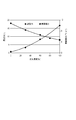
- FIG. 3 shows the evaluation results of the release force (unit: N) and the surface roughness (PV value, unit: nm) of the cured resin for each concentration of pentafluoropropane in the mixed gas.
- the mold release force is a force necessary for separating the mold and the cured resin, and can be measured by a load sensor provided in the substrate chuck 2 or in the vicinity thereof.
- the surface roughness can be measured by observing the surface of the cured resin with a microscope (for example, an atomic force microscope).
- FIG. 3 shows that when the concentration of pentafluoropropane is increased, the releasing force is reduced and the surface roughness of the resin is increased.
- lithography technology for example, a pattern with a line width of 20 nm to 100 nm is transferred, and a finer pattern is required to be transferred. Therefore, even if the surface roughness is increased by several nm, the performance of the device is deteriorated or defective. There is concern about yield decline.
- the concentration of pentafluoropropane may be adjusted to 53% or less. At this time, the amount of the mixed gas dissolved in the acrylic resin is 2.4 mol / L. Further, by setting the concentration of pentafluoropropane to 8% or more, the release force can be reduced by 10% or more compared to the case where the concentration of pentafluoropropane is 0%. At this time, the amount of the mixed gas dissolved in the acrylic resin is 0.36 mol / L.
- the solubility of the readily soluble gas in the resin at 20 ° C. and 1 atm is S mol / L
- the solubility of the hardly soluble gas is D mol / L
- the concentration of the easily soluble gas is C.
- Nitrogen has an advantage over helium in terms of cost.
- the resin filling time can be shortened, or pattern defects can be reduced, and the surface roughness of the resin can be reduced.
- FIG. 5 is a diagram illustrating an imprint apparatus according to the second embodiment.
- the imprint apparatus according to the second embodiment is different from the first embodiment in the configuration of the supply port for supplying the mixed gas.
- the second embodiment is the same as that of 1st Embodiment, and description is abbreviate
- a supply port for supplying a mixed gas is formed in the mold 3.
- a convex portion is formed on the mold 3, and a fine concavo-convex pattern (pattern portion) is formed on the surface of the convex portion.
- a supply port is disposed around the convex portion.
- the first embodiment since it takes several tens of milliseconds from the time when the shot region passes below the gas supply unit 11 until the resin on the shot region comes into contact with the mold 3, it is once dissolved in the resin during that time. There is a risk that the readily soluble gas may escape from the resin. In particular, when the alignment sequence is executed after the shot region and the pattern portion are opposed to each other, this time becomes long, and the easily soluble gas that escapes from the resin tends to increase.
- the supply port can be opposed to the space between the mold 3 and the substrate 1. Accordingly, since the mixed gas can be sprayed onto the shot region until immediately before the resin on the shot region and the mold 3 are brought into contact with each other, the easily soluble gas that escapes from the resin can be reduced.
- the mixed gas supply line 9 in the present embodiment has the same configuration as the mixed gas supply line 20 in the first embodiment, and is connected to the easily soluble gas supply line 33 and the hardly soluble gas supply line 34 via the temperature controller 36. Connected.
- FIG. 6 is a diagram illustrating an imprint apparatus according to the third embodiment.
- the imprint apparatus according to the third embodiment is different from the first embodiment in that the configuration of the supply port for supplying the mixed gas and the dispenser are not provided.
- the configuration of the supply port for supplying the mixed gas and the dispenser are not provided.
- the configuration of the supply port for supplying the mixed gas and the dispenser are not provided.
- the configuration of the supply port for supplying the mixed gas and the dispenser are not provided.
- 1st Embodiment and description is abbreviate
- the supply port 7 for supplying the mixed gas is composed of one partition wall surrounding the mold chuck 4.
- a gas mixture supply line 10 and a discharge line 8 are connected to the supply port 7.
- the mixed gas supply line 10 in the present embodiment has the same configuration as the mixed gas supply line 20 in the first embodiment, and is connected to the easily soluble gas supply line 33 and the hardly soluble gas supply line 34 via the temperature controller 36. Connected.
- the imprint apparatus does not include the dispenser 12 for applying the resin.
- a method of manufacturing a device is a step of transferring (forming) a pattern onto a substrate (wafer, glass plate, film substrate, etc.) using the above-described imprint apparatus (imprinting apparatus). including. Further, the method may include a step of etching the substrate to which the pattern has been transferred. When manufacturing other articles such as patterned media (recording media) and optical elements, other processing steps for processing the substrate to which the pattern has been transferred may be included instead of the etching step.
Landscapes
- Physics & Mathematics (AREA)
- General Physics & Mathematics (AREA)
- Shaping Of Tube Ends By Bending Or Straightening (AREA)
Abstract
樹脂の充填時間を短縮、もしくは、パターン欠損を低減するとともに、樹脂の表面粗さを低減させたインプリント方法もしくはインプリント装置を提供することを目的とする。基板上の樹脂と、パターンが形成されたモールドとを接触させることによって前記基板上に前記パターンを転写するインプリント方法であって、前記基板と前記モールドとの間の空間に所定の気体が満たされている状態で、前記基板上の樹脂と前記モールドとを接触させる工程と、前記樹脂と前記モールドとが接触している状態で前記樹脂を硬化させる工程と、前記樹脂と前記モールドとを離す工程と、を備え、前記所定の気体は、20℃、1気圧において前記樹脂への溶解度が0.36モル/リットル以上である第1の気体と、前記樹脂への溶解度が0.36モル/リットル未満である第2の気体を含むことを特徴とする。
Description
本発明は、インプリント方法、およびインプリント装置に関する。
デバイス(半導体集積回路素子、液晶表示素子等)を製造するためのリソグラフィ技術の一つとして、インプリント方法が知られている。これは、ウェハやガラスプレートなどの基板上の樹脂と、微細なパターンが形成されたモールドとを接触させ、両者を接触させた状態で樹脂を硬化させることによって基板上にパターンを転写する方法である。
このようなインプリント方法において、生産性を向上させるために、パターンの凹部に樹脂が充填されるまでの時間(充填時間)を短縮することや、歩留まりを向上させるために、パターン欠損を低減することが要求されている。
特に、大気中で樹脂とモールドとを接触させる場合には、樹脂とモールドとの間に気体が残りやすいため、充填時間が長くなってしまう。
特許文献1には、充填時間を短縮するために、樹脂とモールドとの間にヘリウムまたは二酸化炭素を供給した後に、樹脂とモールドとを接触させることが記載されている。これらの気体は、充填時間の短縮に寄与することが知られている。
特許文献2には、同様の目的で、凝縮性のガスを供給した後に、樹脂とモールドとを接触させることが記載されている。
非特許文献1、非特許文献2には、樹脂とモールドとの間に凝縮性ガスの一種である1,1,1,3,3ペンタフルオロプロパン(ペンタフルオロプロパン)を供給することが記載されている。これらの非特許文献には、ペンタフルオロプロパンの供給により、硬化前の樹脂の粘性を低下できること、さらに、モールドと硬化後の樹脂とを引き離す力(離型力)を低減させることができることが記載されている。
Hiroshima,Journal of Vacuum Science and Technology B 27(6)(2009)2862-2865
Hiroshima,Journal of Photopolymer Science and Technology Volume23,Number1(2010)45-50
上述のように、ペンタフルオロプロパンを供給することによって、樹脂の粘性を低下させて充填時間を短縮することができ、離型力を低減させてパターン欠損を低減することができる。
本願の発明者が検討した結果、ペンタフルオロプロパンは樹脂に溶解しやすい性質の気体であり、この性質が上述の作用効果をもたらすという知見を得た。
また発明者は、このような気体を供給した場合に、気体を供給しない場合に比べて、硬化後の樹脂の表面粗さが大きくなる現象が生じるという課題を新たに見出した。表面粗さの増大は、樹脂とモールドとを引き離した後に、樹脂中に溶解していた気体が表面から揮発することによって起こったと考えられる。
リソグラフィ技術において、例えば20nm~100nmの線幅のパターンが転写され、さらに微細なパターンの転写が求められているため、数nmの表面粗さの増大であってもデバイスの性能劣化や不良品による歩留まり低下が懸念される。
本願発明は、上述の課題に鑑みてなされたものであり、樹脂の充填時間を短縮、もしくは、パターン欠損を低減するとともに、樹脂の表面粗さを低減させたインプリント方法もしくはインプリント装置を提供することを目的としている。
本発明のインプリント方法は、基板上の樹脂と、パターンが形成されたモールドとを接触させることによって前記基板上に前記パターンを転写するインプリント方法であって、前記基板と前記モールドとの間の空間に所定の気体が満たされている状態で、前記基板上の樹脂と前記モールドとを接触させる工程と、前記樹脂と前記モールドとが接触している状態で前記樹脂を硬化させる工程と、前記樹脂と前記モールドとを離す工程と、を備え、前記所定の気体は、20℃、1気圧において前記樹脂への溶解度が0.36モル/リットル以上である第1の気体と、前記樹脂への溶解度が0.36モル/リットル未満である第2の気体を含むことを特徴としている。
また本発明のインプリント装置は、基板上の樹脂と、パターンが形成されたモールドとを接触させることによって前記基板上に前記パターンを転写するインプリント装置であって、前記基板上の樹脂に対して所定の気体を供給する気体供給部と、前記基板上の樹脂と前記モールドとを接触させる駆動機構前記樹脂と前記モールドとが接触している状態で前記樹脂を硬化させる硬化手段と、を備え、前記所定の気体は、20℃、1気圧において前記樹脂への溶解度が0.36モル/リットル以上である第1の気体と、前記樹脂への溶解度が0.36モル/リットル未満である第2の気体を含むことを特徴としている。
本願発明によれば、樹脂の充填時間を短縮、もしくは、パターン欠損を低減するとともに、樹脂の表面粗さを低減させたインプリント方法もしくはインプリント装置を提供することができる。
以下に、本発明の好ましい実施形態を添付の図面に基づいて詳細に説明する。
(第1実施形態)
図1は、第1実施形態におけるインプリント装置を示す図である。
図1は、第1実施形態におけるインプリント装置を示す図である。
インプリント装置は、基板1上の樹脂と、微細なパターンが形成されたモールド3とを接触させ、両者を接触させた状態で樹脂を硬化させることによって基板1上にパターンを転写する。このようなインプリント装置は、例えば、デバイス(半導体集積回路素子、液晶表示素子等)を製造するために用いられる。基板1として、例えば、シリコンウェハやガラスプレートが用いられる。
インプリント装置として、基板とほぼ同じ大きさのパターンを有するモールドを用いてパターンを一括で転写する方式と、基板よりも小さなパターンを有するモールドを用いて複数回パターンを転写する方式とが知られている。本実施形態では、後者の方式(いわゆる、ステップ&リピート方式)の例について説明するが、これに限られるものではない。後者の方式において、1回の転写に対応する基板上の領域を「ショット領域」と称する。
図1において、モールド3のパターンに垂直な方向をZ軸、Z軸に直交する2軸をX軸、Y軸としている。典型的には、Z軸は鉛直方向と平行である。
インプリント装置は、硬化に用いる光を発光する光源(硬化手段)5と、モールド3を保持するためのモールドチャック(モールド保持部)4と、基板1を保持するための基板チャック(基板保持部)2と、を備える。また、基板1に樹脂を塗布するためのディスペンサ(塗布部)12と、モールド3と基板1との間の空間に所定の気体を供給する気体供給部11とを備える。
本実施形態において、ディスペンサ12と気体供給部11が2つずつ設けられているが、これに限られず、1つずつ設けられていてもよい。
硬化に用いる光として、例えば、紫外光が用いられるが、光の波長はこれに限定されない。また、インプリント装置は、光源5からの光をモールド3に導く光学系を備える。図1において、光学系の一部であるミラー6を示す。
モールド3は、光源5からの光を透過可能に構成され、例えば、石英、シリコン、樹脂、あるいはこれらの組み合わせを含む材料で形成される。本実施形態において、モールド3には凸部が形成され、凸部の表面に微細な凹凸パターン(パターン部)が形成されている。
インプリント装置は、さらに、モールドチャック4と基板チャック2との相対位置を調整するための駆動機構13を備える。
駆動機構13は、モールド3と、基板1上に塗布された樹脂とを接触させるために用いられ、両者を離すためにも用いられる。駆動機構13は、モールドチャック4及び基板チャック2の少なくとも一方をZ軸に沿って移動させる。本実施形態では、一例として、モールドチャック4のみをZ軸に沿って移動させて、モールド3と樹脂とを接触させている。
また、駆動機構13は、モールド3と、基板1とのX軸およびY軸に沿う方向の相対位置を調整するために用いられる。駆動機構13は、モールドチャック4及び基板チャック2の少なくとも一方をX軸およびY軸に沿って移動させる。本実施形態では、一例として、基板チャック2のみをX軸およびY軸に沿って移動させている。
さらに、駆動機構13は、ディスペンサ12と、基板1とのX軸およびY軸に沿う方向の相対位置を調整するために用いられる。駆動機構13は、ディスペンサ12及び基板チャック2の少なくとも一方をX軸およびY軸に沿って移動させる。本実施形態では、一例として、基板チャック2のみをX軸およびY軸に沿って移動させている。
駆動機構13として、例えばリニアモータが好適に用いられる。図1は模式的な図であり、駆動機構13の配置やストロークは適宜設計可能である。
また、インプリント装置は、CPU、メモリを含む制御部14を備える。制御部14は、インプリント装置のシーケンスを制御し、駆動機構13を制御し、ディスペンサ12を制御する。図において1つの制御部が示されているが、制御対象に応じて複数の制御部が設けられていてもよい。
図2(a)、(b)は、1つの気体供給部11の細部を示す図である。
気体供給部11は、基板1とモールド3との間の空間を所定の気体で満たすために用いられる。
気体供給部11は、易溶性気体供給ライン33(易溶性気体供給部)と、難溶性気体供給ライン34(難溶性気体供給部)と、易溶性気体と難溶性気体との混合気体を供給するための混合気体供給ライン20とを含む。
易溶性気体供給ライン33と難溶性気体供給ライン34には、それぞれ、流量を調整するための調整弁が設けられる。流量制御部37が調整弁を調整することによって、混合気体に含まれる各気体の濃度を調整することができる。また、温度制御部36は、混合気体の温度を調整することができる。典型的には、各ユニットは、温度が20℃程度に管理されたチャンバー内に配置されるため、温度制御部36は、20℃程度の温度になるように調整される。
気体供給部11は、不活性気体を供給するための不活性気体供給ライン35と、気体を排出するための排出ライン20と、を含む。不活性気体供給ライン35には、流量を調整するための調整弁が設けられる。
気体供給部11は、供給口(第1の供給口)16と、排出口31と、供給口(第2の供給口)32とを含む。
図2(b)は、これらの供給口および排出口を基板1側から見た図である。図示されるように、供給口および排出口は、1つもしくは複数の隔壁により構成され、内側から順に供給口16、排出口31、供給口32が配置される。また、排出口31は供給口16の周囲を囲むように設けられ、供給口32は排出口31の周囲を囲むように設けられる。
供給口16は混合気体供給ライン20に接続され、供給口32は不活性気体供給ライン35に接続され、排出口31は排出ライン19に接続される。
なお、気体供給部11の構成は、この形態に限られるものではない。例えば、排出口31及び排出ライン19は、供給口16からの気体が基板チャック2の周囲への漏れを低減するために設けられるものであり、周囲への漏れを低減する必要がない場合には不要である。
リソグラフィ装置では、例えば20nm~100nmの線幅のパターンを転写するため、基板チャック2を高い精度で位置調整する必要がある。そのため、典型的には、基板チャック2の位置調整にはレーザー干渉計などの位置計測手段が用いられる。上述の気体の漏れは、レーザー干渉計の計測光の光路において屈折率変動をもたらすため、位置調整の精度を悪化させる可能性がある。したがって、排出口を設けることによって、位置調整の精度を向上させることができる。
不活性気体供給ライン35及び供給口32も、屈折率変動を低減するために用いられる。供給口32から供給される気体は、排出口31を介して排出され、これにより、供給口16から供給される気体はシールされる。
また、本実施形態において、易溶性気体と難溶性気体との混合気体を供給する形態としているが、易溶性気体と難溶性気体をそれぞれ独立の供給口から供給するようにしてもよい。「所定の気体(混合気体)を供給する気体供給部」は、このような形態を含むものとする。 気体供給部11は、XY平面において、モールドチャック4とディスペンサ12の間に配置される。気体供給部11から混合気体を供給しながら基板チャック2を移動させることによって、モールド3と基板1との間の空間に混合気体を供給することができる。
つまり、「モールド3と基板1との間の空間に所定の気体(混合気体)を供給する気体供給部」は、基板1上の樹脂に対して混合気体を供給し、その後、基板1をモールド3の下方に移動させる形態を含む。
つづいて、本実施形態のインプリント方法について説明する。
インプリント装置に搬入された基板1は、不図示の搬送手段により基板チャック2上に搭載され、不図示の位置検出系により位置合わせされる。基板1の搬送シーケンスおよび位置合わせシーケンスについては、公知の技術を適用可能であるものとして、説明を省略する。
ステップS110において、駆動機構は、パターンを転写すべき基板1上のショット領域とディスペンサ12の吐出部とを対向させるように、基板1のX軸およびY軸に沿う方向の位置を調整する。
ステップS120において、ディスペンサ12は、パターンを転写すべき基板1上のショット領域に樹脂を塗布する。
ステップS130において、気体供給部11は、基板1とモールド3との間の空間に混合気体を供給する。混合気体は、20℃、1気圧において樹脂への溶解度が0.36モル/L(リットル)以上である易溶性気体(第1の気体)と、樹脂への溶解度が0.36モル/L未満である難溶性気体(第2の気体)を含む。易溶性気体と難溶性気体の詳細については、後述する。
混合気体は、ステップS120よりも以前から供給されていてもよい。
ステップS140において、駆動機構は、パターンを転写すべき基板1上のショット領域とモールド3のパターン部とを対向させるように、基板1のX軸およびY軸に沿う方向の位置を調整する。
気体供給部11から混合気体を供給しながら基板チャック2を移動させることによって、混合気体がモールド3と基板1との間を混合気体で満たすことができる。混合気体の供給と基板チャック2の移動とを並行して行うことで、混合気体はモールド3のパターン部と基板1のショット領域との間に引きずり込まれ、効率的に両者の間を混合気体で満たすことができる。なお、「混合気体で満たされている状態」とは、混合気体以外の気体がわずかに存在している状態を除外するものではない。
ステップS150において、駆動機構は、基板1とモールド3との間の空間に混合気体が満たされている状態で、樹脂とモールド3とを接触させる。
ステップS160において、樹脂とモールド3とが接触している状態で樹脂を硬化させる。具体的には、光源5が、モールド3を介して、樹脂に光を照射する。
ステップS170において、駆動機構は、樹脂とモールド3とを離す。
以上のステップにより、基板1上のショット領域にモールド3のパターンが転写される。
基板上に転写すべきショット領域が存在する場合には、他のショット領域に対して、ステップS110~S170を行う。
易溶性気体と難溶性気体について説明する。
本実施形態において、樹脂として、光硬化性を有するアクリル系樹脂を使用し、易溶性気体としてペンタフルオロプロパンを使用し、難溶性気体としてヘリウムを使用した例を説明する。
ペンタフルオロプロパンは、20℃、1気圧において、アクリル系樹脂1mLへの溶解量はおよそ600mg、すなわち4.48モル/Lであった。ヘリウムは、20℃、1気圧において、アクリル系樹脂1mLへのヘリウムの溶解量はおよそ0.002mg、すなわち0.0005モル/Lであった。
ペンタフルオロプロパンの供給により、硬化前の樹脂の粘性を低下させることができ、さらに、モールドと硬化後の樹脂とを引き離す力(離型力)を低減させることができる。また、ヘリウムは、樹脂とモールドとの間の空間から周囲に拡散しやすいため、充填時間の短縮に有利である。
図3は、混合気体におけるペンタフルオロプロパンの濃度毎の、離型力(単位はN)および硬化後の樹脂の表面粗さ(PV値、単位はnm)の評価結果である。離型力は、モールドと硬化後の樹脂とを離すために必要な力であり、基板チャック2もしくはその近傍に設けた荷重センサにより計測することができる。また、表面粗さは、硬化後の樹脂の表面を顕微鏡(例えば、原子間力顕微鏡)で観察することで計測できる。
図3から、ペンタフルオロプロパンの濃度を高くすると、離型力が小さくなり、樹脂の表面粗さが大きくなることが分かる。
リソグラフィ技術において、例えば20nm~100nmの線幅のパターンが転写され、さらに微細なパターンの転写が求められているため、数nmの表面粗さの増大であってもデバイスの性能劣化や不良品による歩留まり低下が懸念される。
許容できる表面粗さが例えば4nmである場合には、ペンタフルオロプロパンの濃度を53%以下に調整すればよい。このとき、混合気体のアクリル樹脂への溶解量は2.4モル/Lである。また、ペンタフルオロプロパンの濃度を8%以上にすることで、ペンタフルオロプロパンの濃度が0%の場合に比べて離型力を10%以上低減できる。このとき、混合気体のアクリル樹脂への溶解量は0.36モル/Lである。
線幅が25nmのパターンが形成されたマスクを用いて実験を行ったところ、ペンタフルオロプロパンの濃度を0%にした場合に10%前後のパターン欠損が確認され、ペンタフルオロプロパンの濃度を53%にした場合にパターン欠損が確認されなかった。
上記について、より一般化すると、20℃、1気圧における樹脂への易溶性気体の溶解度をSモル/Lとし、難溶性気体の溶解度をDモル/Lとし、易溶性気体の濃度をCとした場合に、次の式を満たす場合に良好なパターンが得られるという知見を得た。
0.36 ≦ {S・C+D・(1-C)} ≦ 2.4 (式1)
{S・C+D・(1-C)}が0.2よりも小さい場合には、離型力を低減させる効果が小さく、{S・C+D・(1-C)}が1.2を超える場合には、樹脂に溶解される気体が多くなり過ぎて表面粗さが大きくなってしまう。
0.36 ≦ {S・C+D・(1-C)} ≦ 2.4 (式1)
{S・C+D・(1-C)}が0.2よりも小さい場合には、離型力を低減させる効果が小さく、{S・C+D・(1-C)}が1.2を超える場合には、樹脂に溶解される気体が多くなり過ぎて表面粗さが大きくなってしまう。
例えば、ヘリウムの代わりに窒素(窒素のアクリル系樹脂1mLへの溶解量は約0.088mg、すなわち約0.00314モル/L)を用いた場合であっても、式1から適切な濃度を決定できる。窒素はコストの面でヘリウムよりも有利である。
以上のように、本実施形態によれば、樹脂の充填時間を短縮、もしくは、パターン欠損を低減するとともに、樹脂の表面粗さを低減させることが可能となる。
(第2実施形態)
図5は、第2実施形態のインプリント装置を示す図である。第2実施形態のインプリント装置は、混合気体を供給する供給口の構成が第1実施形態とは異なる。それ以外の構成については、第1実施形態と同様であるものとして、説明を省略する。
図5は、第2実施形態のインプリント装置を示す図である。第2実施形態のインプリント装置は、混合気体を供給する供給口の構成が第1実施形態とは異なる。それ以外の構成については、第1実施形態と同様であるものとして、説明を省略する。
本実施形態において、混合気体を供給するための供給口がモールド3に形成されている。モールド3には凸部が形成され、凸部の表面に微細な凹凸パターン(パターン部)が形成されている。この凸部の周辺に供給口が配置されている。
第1実施形態において、ショット領域が気体供給部11の下方を通過してからショット領域上の樹脂とモールド3とを接触させるまでに数十ミリ秒の時間がかかるため、その間に一度樹脂に溶解した易溶性気体が樹脂から抜けてしまう恐れがある。特に、ショット領域とパターン部とを対向させた後に、位置合わせのシーケンスを実行する場合にはこの時間が長くなり、樹脂から抜ける易溶性気体は増加しやすい。
本実施形態によれば、供給口をモールド3と基板1との間の空間に対向させることができる。これにより、ショット領域上の樹脂とモールド3とを接触させる直前までショット領域に混合気体を吹き付けることが可能となるため、樹脂から抜ける易溶性気体を低減することができる。
本実施形態における混合気体供給ライン9は、第1実施形態における混合気体供給ライン20と同様の構成であり、温度制御部36を介して、易溶性気体供給ライン33と難溶性気体供給ライン34に接続される。
なお、本実施形態において、第1実施形態と同様に不活性気体を供給するための供給口と、気体を排出するための排出口を設けてもよい。
(第3実施形態)
図6は、第3実施形態のインプリント装置を示す図である。第3実施形態のインプリント装置は、混合気体を供給する供給口の構成と、ディスペンサを備えない点が第1実施形態とは異なる。それ以外の構成については、第1実施形態と同様であるものとして、説明を省略する。
図6は、第3実施形態のインプリント装置を示す図である。第3実施形態のインプリント装置は、混合気体を供給する供給口の構成と、ディスペンサを備えない点が第1実施形態とは異なる。それ以外の構成については、第1実施形態と同様であるものとして、説明を省略する。
本実施形態において、混合気体を供給する供給口7は、モールドチャック4の周囲を囲む1つの隔壁から構成される。供給口7には、混合気体供給ライン10と、排出ライン8が接続される。
本実施形態における混合気体供給ライン10は、第1実施形態における混合気体供給ライン20と同様の構成であり、温度制御部36を介して、易溶性気体供給ライン33と難溶性気体供給ライン34に接続される。
なお、本実施形態において、第1実施形態と同様に不活性気体を供給するための供給口を設けても良い。
本実施形態において、基板1をインプリント装置に搬入する前に、基板の全面に樹脂を塗布する。したがって、インプリント装置は、樹脂を塗布するためのディスペンサ12を備えていない。
(デバイスの製造方法)
デバイス(半導体集積回路素子、液晶表示素子等)の製造方法は、前述したインプリント装置(押印装置)を用いて基板(ウェハ、ガラスプレート、フィルム状基板等)にパターンを転写(形成)するステップを含む。さらに、パターンを転写された前記基板をエッチングするステップを含みうる。なお、パターンドメディア(記録媒体)や光学素子などの他の物品を製造する場合には、エッチングステップの代わりに、パターンを転写された前記基板を加工する他の加工ステップを含みうる。
デバイス(半導体集積回路素子、液晶表示素子等)の製造方法は、前述したインプリント装置(押印装置)を用いて基板(ウェハ、ガラスプレート、フィルム状基板等)にパターンを転写(形成)するステップを含む。さらに、パターンを転写された前記基板をエッチングするステップを含みうる。なお、パターンドメディア(記録媒体)や光学素子などの他の物品を製造する場合には、エッチングステップの代わりに、パターンを転写された前記基板を加工する他の加工ステップを含みうる。
以上、本発明の実施の形態を説明してきたが、本発明はこれらの実施の形態に限定されず、その要旨の範囲内において様々な変形及び変更が可能である。
本願は、2013年01月17日提出の日本国特許出願特願2013-006316を基礎として優先権を主張するものであり、その記載内容の全てをここに援用する。
1 基板
2 基板チャック
3 モールド
4 モールドチャック
5 光源
11 気体供給部
12 ディスペンサ
13 駆動機構
20 混合気体供給ライン
2 基板チャック
3 モールド
4 モールドチャック
5 光源
11 気体供給部
12 ディスペンサ
13 駆動機構
20 混合気体供給ライン
Claims (6)
- 基板上の樹脂と、パターンが形成されたモールドとを接触させることによって前記基板上に前記パターンを転写するインプリント方法であって、
前記基板と前記モールドとの間の空間に所定の気体が満たされている状態で、前記基板上の樹脂と前記モールドとを接触させる工程と、
前記樹脂と前記モールドとが接触している状態で前記樹脂を硬化させる工程と、
前記樹脂と前記モールドとを離す工程と、を備え、
前記所定の気体は、20℃、1気圧において前記樹脂への溶解度が0.36モル/リットル以上である第1の気体と、前記樹脂への溶解度が0.36モル/リットル未満である第2の気体を含むことを特徴とするインプリント方法。 - 20℃、1気圧における樹脂への第1の気体の溶解度をSモル/Lとし、第2の気体の溶解度をDモル/Lとし、第1の気体の濃度をCとした場合に、前記所定の気体は、
0.36 ≦ {S・C+D・(1-C)} ≦ 2.4
を満たすことを特徴とする請求項1に記載のインプリント方法。 - 前記第1の気体と前記第2の気体を混合させた混合気体を供給する工程を備えることを特徴とする請求項1または2に記載のインプリント方法。
- 前記第2の気体がヘリウムまたは窒素を含むことを特徴とする請求項1乃至3のいずれか1項に記載のインプリント方法。
- 前記第1の気体がペンタフルオロプロパンを含むことを特徴とする請求項1乃至4のいずれか1項に記載のインプリント方法。
- 基板上の樹脂と、パターンが形成されたモールドとを接触させることによって前記基板上に前記パターンを転写するインプリント装置であって、
前記基板上の樹脂に対して所定の気体を供給する気体供給部と、
前記基板上の樹脂と前記モールドとを接触させる駆動機構と、
前記樹脂と前記モールドとが接触している状態で前記樹脂を硬化させる硬化手段と、
を備え、
前記所定の気体は、20℃、1気圧において前記樹脂への溶解度が0.36モル/リットル以上である第1の気体と、前記樹脂への溶解度が0.36モル/リットル未満である第2の気体を含むことを特徴とするインプリント装置。
Priority Applications (2)
| Application Number | Priority Date | Filing Date | Title |
|---|---|---|---|
| KR1020157021933A KR20150109399A (ko) | 2013-01-17 | 2014-01-15 | 임프린트 방법 및 임프린트 장치 |
| US14/333,226 US20140327183A1 (en) | 2012-01-19 | 2014-07-16 | Imprint method and imprint apparatus |
Applications Claiming Priority (2)
| Application Number | Priority Date | Filing Date | Title |
|---|---|---|---|
| JP2013006316A JP5882922B2 (ja) | 2012-01-19 | 2013-01-17 | インプリント方法、およびインプリント装置 |
| JP2013-006316 | 2013-01-17 |
Related Child Applications (1)
| Application Number | Title | Priority Date | Filing Date |
|---|---|---|---|
| US14/333,226 Continuation US20140327183A1 (en) | 2012-01-19 | 2014-07-16 | Imprint method and imprint apparatus |
Publications (1)
| Publication Number | Publication Date |
|---|---|
| WO2014112495A1 true WO2014112495A1 (ja) | 2014-07-24 |
Family
ID=51210865
Family Applications (1)
| Application Number | Title | Priority Date | Filing Date |
|---|---|---|---|
| PCT/JP2014/050500 Ceased WO2014112495A1 (ja) | 2012-01-19 | 2014-01-15 | インプリント方法、およびインプリント装置 |
Country Status (2)
| Country | Link |
|---|---|
| KR (1) | KR20150109399A (ja) |
| WO (1) | WO2014112495A1 (ja) |
Cited By (1)
| Publication number | Priority date | Publication date | Assignee | Title |
|---|---|---|---|---|
| WO2016052473A1 (ja) * | 2014-09-30 | 2016-04-07 | 富士フイルム株式会社 | 多孔質体の製造方法、多孔質体、デバイスの製造方法、デバイス、配線構造の製造方法、配線構造 |
Families Citing this family (2)
| Publication number | Priority date | Publication date | Assignee | Title |
|---|---|---|---|---|
| JP6808386B2 (ja) * | 2016-07-12 | 2021-01-06 | キヤノン株式会社 | インプリント装置および物品製造方法 |
| JP6978853B2 (ja) * | 2017-05-15 | 2021-12-08 | キヤノン株式会社 | インプリント装置、及び物品製造方法 |
Citations (3)
| Publication number | Priority date | Publication date | Assignee | Title |
|---|---|---|---|---|
| JP2006352121A (ja) * | 2005-06-13 | 2006-12-28 | Asml Netherlands Bv | インプリント・リソグラフィ |
| JP2012164785A (ja) * | 2011-02-07 | 2012-08-30 | Canon Inc | インプリント装置、および、物品の製造方法 |
| JP2013254782A (ja) * | 2012-06-05 | 2013-12-19 | Canon Inc | インプリント方法およびインプリント装置、それを用いた物品の製造方法 |
-
2014
- 2014-01-15 KR KR1020157021933A patent/KR20150109399A/ko not_active Ceased
- 2014-01-15 WO PCT/JP2014/050500 patent/WO2014112495A1/ja not_active Ceased
Patent Citations (3)
| Publication number | Priority date | Publication date | Assignee | Title |
|---|---|---|---|---|
| JP2006352121A (ja) * | 2005-06-13 | 2006-12-28 | Asml Netherlands Bv | インプリント・リソグラフィ |
| JP2012164785A (ja) * | 2011-02-07 | 2012-08-30 | Canon Inc | インプリント装置、および、物品の製造方法 |
| JP2013254782A (ja) * | 2012-06-05 | 2013-12-19 | Canon Inc | インプリント方法およびインプリント装置、それを用いた物品の製造方法 |
Cited By (5)
| Publication number | Priority date | Publication date | Assignee | Title |
|---|---|---|---|---|
| WO2016052473A1 (ja) * | 2014-09-30 | 2016-04-07 | 富士フイルム株式会社 | 多孔質体の製造方法、多孔質体、デバイスの製造方法、デバイス、配線構造の製造方法、配線構造 |
| KR20170048465A (ko) * | 2014-09-30 | 2017-05-08 | 후지필름 가부시키가이샤 | 다공질체의 제조 방법, 다공질체, 디바이스의 제조 방법, 디바이스, 배선 구조의 제조 방법, 배선 구조 |
| JPWO2016052473A1 (ja) * | 2014-09-30 | 2017-08-31 | 富士フイルム株式会社 | 多孔質体の製造方法、多孔質体、デバイスの製造方法、デバイス、配線構造の製造方法、配線構造 |
| KR101885096B1 (ko) | 2014-09-30 | 2018-08-03 | 후지필름 가부시키가이샤 | 다공질체의 제조 방법, 다공질체, 디바이스의 제조 방법, 디바이스, 배선 구조의 제조 방법, 배선 구조 |
| US10373863B2 (en) | 2014-09-30 | 2019-08-06 | Fujifilm Corporation | Method of manufacturing porous body, porous body, method of manufacturing device, device, method of manufacturing wiring structure, and wiring structure |
Also Published As
| Publication number | Publication date |
|---|---|
| KR20150109399A (ko) | 2015-10-01 |
Similar Documents
| Publication | Publication Date | Title |
|---|---|---|
| JP6184538B2 (ja) | インプリント方法、およびインプリント装置 | |
| JP5364533B2 (ja) | インプリントシステムおよびインプリント方法 | |
| US9770850B2 (en) | Imprint apparatus and article manufacturing method | |
| JP2012164785A (ja) | インプリント装置、および、物品の製造方法 | |
| JP6525628B2 (ja) | インプリント装置及び物品の製造方法 | |
| KR102011558B1 (ko) | 임프린트 장치, 임프린트 방법, 및 물품 제조 방법 | |
| KR102809595B1 (ko) | 성형 장치, 결정 방법 및 물품 제조 방법 | |
| JP2019186477A (ja) | インプリント装置、インプリント方法、および物品製造方法 | |
| JP5932500B2 (ja) | インプリント方法およびインプリント装置、それを用いた物品の製造方法 | |
| JP2016054232A (ja) | インプリント装置 | |
| US11584048B2 (en) | Molding apparatus, molding method, and manufacturing method of article | |
| WO2014112495A1 (ja) | インプリント方法、およびインプリント装置 | |
| US20260061691A1 (en) | Imprint device, imprint method, storage medium, and article manufacturing method | |
| TW200938960A (en) | Immersion lithographic apparatus and device manufacturing method | |
| JP2017208424A (ja) | インプリント装置、及び物品の製造方法 | |
| JP7262930B2 (ja) | 型を用いて基板上の組成物を成形する成形装置、成形方法、および物品の製造方法 | |
| JP7071089B2 (ja) | 保持装置、保持方法、リソグラフィ装置および、物品の製造方法 | |
| KR20220027764A (ko) | 기판 처리 방법, 기판 보유지지 장치, 성형 장치, 및 물품 제조 방법 | |
| JP2022163679A (ja) | インプリント装置、インプリント方法及び物品の製造方法 | |
| JP6304921B2 (ja) | インプリント方法およびインプリント装置、それを用いた物品の製造方法 | |
| JP7064310B2 (ja) | インプリント装置、および物品製造方法 | |
| US12228855B2 (en) | Imprint apparatus, imprint method, article manufacturing method, and storage medium | |
| US20220334471A1 (en) | Imprint apparatus, imprint method and article manufacturing method | |
| JP6250022B2 (ja) | インプリント装置、物品の製造方法、及びインプリント方法 | |
| WO2018025756A1 (ja) | インプリント装置、及び物品製造方法 |
Legal Events
| Date | Code | Title | Description |
|---|---|---|---|
| 121 | Ep: the epo has been informed by wipo that ep was designated in this application |
Ref document number: 14740725 Country of ref document: EP Kind code of ref document: A1 |
|
| NENP | Non-entry into the national phase |
Ref country code: DE |
|
| ENP | Entry into the national phase |
Ref document number: 20157021933 Country of ref document: KR Kind code of ref document: A |
|
| 122 | Ep: pct application non-entry in european phase |
Ref document number: 14740725 Country of ref document: EP Kind code of ref document: A1 |