WO2014104253A1 - 車両用操舵装置 - Google Patents
車両用操舵装置 Download PDFInfo
- Publication number
- WO2014104253A1 WO2014104253A1 PCT/JP2013/085002 JP2013085002W WO2014104253A1 WO 2014104253 A1 WO2014104253 A1 WO 2014104253A1 JP 2013085002 W JP2013085002 W JP 2013085002W WO 2014104253 A1 WO2014104253 A1 WO 2014104253A1
- Authority
- WO
- WIPO (PCT)
- Prior art keywords
- steering
- motor
- control
- abnormality diagnosis
- sensor
- Prior art date
Links
- 230000005856 abnormality Effects 0.000 claims abstract description 163
- 238000003745 diagnosis Methods 0.000 claims abstract description 143
- 230000002159 abnormal effect Effects 0.000 claims abstract description 81
- 238000001514 detection method Methods 0.000 claims abstract description 49
- 238000012545 processing Methods 0.000 claims description 85
- 238000006243 chemical reaction Methods 0.000 claims description 54
- 210000000078 claw Anatomy 0.000 claims description 45
- 230000008878 coupling Effects 0.000 claims description 42
- 238000010168 coupling process Methods 0.000 claims description 42
- 238000005859 coupling reaction Methods 0.000 claims description 42
- 230000004044 response Effects 0.000 claims description 22
- 230000007246 mechanism Effects 0.000 claims description 8
- 230000005540 biological transmission Effects 0.000 claims description 7
- 230000006870 function Effects 0.000 description 108
- 230000001133 acceleration Effects 0.000 description 33
- 238000000034 method Methods 0.000 description 21
- 230000008569 process Effects 0.000 description 19
- 238000004891 communication Methods 0.000 description 13
- 230000002093 peripheral effect Effects 0.000 description 13
- 230000008859 change Effects 0.000 description 10
- 230000033001 locomotion Effects 0.000 description 9
- 230000000694 effects Effects 0.000 description 7
- 238000012544 monitoring process Methods 0.000 description 5
- 238000010586 diagram Methods 0.000 description 4
- 230000004913 activation Effects 0.000 description 3
- 230000009118 appropriate response Effects 0.000 description 3
- 230000009471 action Effects 0.000 description 2
- 238000013461 design Methods 0.000 description 2
- 230000006872 improvement Effects 0.000 description 2
- 238000012423 maintenance Methods 0.000 description 2
- 239000002184 metal Substances 0.000 description 2
- 230000004043 responsiveness Effects 0.000 description 2
- 230000007704 transition Effects 0.000 description 2
- 206010000117 Abnormal behaviour Diseases 0.000 description 1
- 230000003321 amplification Effects 0.000 description 1
- 230000002547 anomalous effect Effects 0.000 description 1
- 239000010426 asphalt Substances 0.000 description 1
- 230000000903 blocking effect Effects 0.000 description 1
- 239000002131 composite material Substances 0.000 description 1
- 239000000428 dust Substances 0.000 description 1
- 238000001914 filtration Methods 0.000 description 1
- 239000012530 fluid Substances 0.000 description 1
- 239000000446 fuel Substances 0.000 description 1
- 238000002347 injection Methods 0.000 description 1
- 239000007924 injection Substances 0.000 description 1
- 238000003780 insertion Methods 0.000 description 1
- 230000037431 insertion Effects 0.000 description 1
- 239000007788 liquid Substances 0.000 description 1
- 239000000696 magnetic material Substances 0.000 description 1
- 238000003199 nucleic acid amplification method Methods 0.000 description 1
- 230000035699 permeability Effects 0.000 description 1
- 230000009467 reduction Effects 0.000 description 1
- 238000000926 separation method Methods 0.000 description 1
- 238000007493 shaping process Methods 0.000 description 1
- 238000012546 transfer Methods 0.000 description 1
- 238000004804 winding Methods 0.000 description 1
Images


Classifications
-
- B—PERFORMING OPERATIONS; TRANSPORTING
- B62—LAND VEHICLES FOR TRAVELLING OTHERWISE THAN ON RAILS
- B62D—MOTOR VEHICLES; TRAILERS
- B62D5/00—Power-assisted or power-driven steering
- B62D5/04—Power-assisted or power-driven steering electrical, e.g. using an electric servo-motor connected to, or forming part of, the steering gear
- B62D5/0457—Power-assisted or power-driven steering electrical, e.g. using an electric servo-motor connected to, or forming part of, the steering gear characterised by control features of the drive means as such
- B62D5/0481—Power-assisted or power-driven steering electrical, e.g. using an electric servo-motor connected to, or forming part of, the steering gear characterised by control features of the drive means as such monitoring the steering system, e.g. failures
- B62D5/0487—Power-assisted or power-driven steering electrical, e.g. using an electric servo-motor connected to, or forming part of, the steering gear characterised by control features of the drive means as such monitoring the steering system, e.g. failures detecting motor faults
-
- B—PERFORMING OPERATIONS; TRANSPORTING
- B62—LAND VEHICLES FOR TRAVELLING OTHERWISE THAN ON RAILS
- B62D—MOTOR VEHICLES; TRAILERS
- B62D5/00—Power-assisted or power-driven steering
- B62D5/001—Mechanical components or aspects of steer-by-wire systems, not otherwise provided for in this maingroup
-
- B—PERFORMING OPERATIONS; TRANSPORTING
- B62—LAND VEHICLES FOR TRAVELLING OTHERWISE THAN ON RAILS
- B62D—MOTOR VEHICLES; TRAILERS
- B62D5/00—Power-assisted or power-driven steering
- B62D5/001—Mechanical components or aspects of steer-by-wire systems, not otherwise provided for in this maingroup
- B62D5/003—Backup systems, e.g. for manual steering
-
- B—PERFORMING OPERATIONS; TRANSPORTING
- B62—LAND VEHICLES FOR TRAVELLING OTHERWISE THAN ON RAILS
- B62D—MOTOR VEHICLES; TRAILERS
- B62D5/00—Power-assisted or power-driven steering
- B62D5/04—Power-assisted or power-driven steering electrical, e.g. using an electric servo-motor connected to, or forming part of, the steering gear
- B62D5/0457—Power-assisted or power-driven steering electrical, e.g. using an electric servo-motor connected to, or forming part of, the steering gear characterised by control features of the drive means as such
- B62D5/046—Controlling the motor
-
- B—PERFORMING OPERATIONS; TRANSPORTING
- B62—LAND VEHICLES FOR TRAVELLING OTHERWISE THAN ON RAILS
- B62D—MOTOR VEHICLES; TRAILERS
- B62D5/00—Power-assisted or power-driven steering
- B62D5/04—Power-assisted or power-driven steering electrical, e.g. using an electric servo-motor connected to, or forming part of, the steering gear
- B62D5/0457—Power-assisted or power-driven steering electrical, e.g. using an electric servo-motor connected to, or forming part of, the steering gear characterised by control features of the drive means as such
- B62D5/0481—Power-assisted or power-driven steering electrical, e.g. using an electric servo-motor connected to, or forming part of, the steering gear characterised by control features of the drive means as such monitoring the steering system, e.g. failures
- B62D5/0484—Power-assisted or power-driven steering electrical, e.g. using an electric servo-motor connected to, or forming part of, the steering gear characterised by control features of the drive means as such monitoring the steering system, e.g. failures for reaction to failures, e.g. limp home
-
- F—MECHANICAL ENGINEERING; LIGHTING; HEATING; WEAPONS; BLASTING
- F16—ENGINEERING ELEMENTS AND UNITS; GENERAL MEASURES FOR PRODUCING AND MAINTAINING EFFECTIVE FUNCTIONING OF MACHINES OR INSTALLATIONS; THERMAL INSULATION IN GENERAL
- F16D—COUPLINGS FOR TRANSMITTING ROTATION; CLUTCHES; BRAKES
- F16D27/00—Magnetically- or electrically- actuated clutches; Control or electric circuits therefor
-
- F—MECHANICAL ENGINEERING; LIGHTING; HEATING; WEAPONS; BLASTING
- F16—ENGINEERING ELEMENTS AND UNITS; GENERAL MEASURES FOR PRODUCING AND MAINTAINING EFFECTIVE FUNCTIONING OF MACHINES OR INSTALLATIONS; THERMAL INSULATION IN GENERAL
- F16D—COUPLINGS FOR TRANSMITTING ROTATION; CLUTCHES; BRAKES
- F16D41/00—Freewheels or freewheel clutches
- F16D41/06—Freewheels or freewheel clutches with intermediate wedging coupling members between an inner and an outer surface
- F16D41/064—Freewheels or freewheel clutches with intermediate wedging coupling members between an inner and an outer surface the intermediate members wedging by rolling and having a circular cross-section, e.g. balls
-
- F—MECHANICAL ENGINEERING; LIGHTING; HEATING; WEAPONS; BLASTING
- F16—ENGINEERING ELEMENTS AND UNITS; GENERAL MEASURES FOR PRODUCING AND MAINTAINING EFFECTIVE FUNCTIONING OF MACHINES OR INSTALLATIONS; THERMAL INSULATION IN GENERAL
- F16D—COUPLINGS FOR TRANSMITTING ROTATION; CLUTCHES; BRAKES
- F16D41/00—Freewheels or freewheel clutches
- F16D41/06—Freewheels or freewheel clutches with intermediate wedging coupling members between an inner and an outer surface
- F16D41/08—Freewheels or freewheel clutches with intermediate wedging coupling members between an inner and an outer surface with provision for altering the freewheeling action
- F16D41/086—Freewheels or freewheel clutches with intermediate wedging coupling members between an inner and an outer surface with provision for altering the freewheeling action the intermediate members being of circular cross-section and wedging by rolling
- F16D41/088—Freewheels or freewheel clutches with intermediate wedging coupling members between an inner and an outer surface with provision for altering the freewheeling action the intermediate members being of circular cross-section and wedging by rolling the intermediate members being of only one size and wedging by a movement not having an axial component, between inner and outer races, one of which is cylindrical
-
- F—MECHANICAL ENGINEERING; LIGHTING; HEATING; WEAPONS; BLASTING
- F16—ENGINEERING ELEMENTS AND UNITS; GENERAL MEASURES FOR PRODUCING AND MAINTAINING EFFECTIVE FUNCTIONING OF MACHINES OR INSTALLATIONS; THERMAL INSULATION IN GENERAL
- F16D—COUPLINGS FOR TRANSMITTING ROTATION; CLUTCHES; BRAKES
- F16D41/00—Freewheels or freewheel clutches
- F16D41/06—Freewheels or freewheel clutches with intermediate wedging coupling members between an inner and an outer surface
- F16D2041/0601—Freewheels or freewheel clutches with intermediate wedging coupling members between an inner and an outer surface with a sliding bearing or spacer
Definitions
- the present invention relates to a steering apparatus for a vehicle, which is used to change a traveling direction of a vehicle to a desired direction.
- Some recent vehicles employ a By Wire type steering device, which converts a driver's steering intention into an electric signal through an electric wire and transmits the electric signal to a steering wheel.
- a bi-wire type steering device converts a driver's steering intention into an electric signal through an electric wire and transmits the electric signal to a steering wheel.
- the operation direction and the operation amount of the steering wheel by the driver are converted into an electric signal, and the electric signal is supplied to the steering device including the steering motor. Then, the steering device operates to steer the steered wheels according to the driver's steering intention by driving the steering motor according to the electric signal (see, for example, Patent Document 1).
- the bi-wire type steering device for example, while traveling on a rough road surface like a rut, one of a pair of steered wheels in the vehicle width direction is located on the road surface portion with the rough surface. Even if it gets stuck, it is possible to suppress a situation where a yaw moment is generated in the vehicle and the steering wheel is taken. As a result, the operation load on the steering wheel by the driver can be reduced.
- the steering device has a main steering motor and a sub steering motor, and is obtained by calculation from the steering wheel angle sensor and the vehicle speed sensor
- the turning current command value of both motors is calculated from the turning command angle and the signal from the motor angle sensor, and whether the sign of the command value is different or not, and the absolute value of the difference between the two is the abnormality judgment threshold value Based on whether or not it is the above, abnormality diagnosis of the steering device is performed.
- abnormality diagnosis of the steering motor is performed using the first steering command angle and the first steering command angle without using the magnitude of the current flowing through the steering motor.
- Difference between the first steering current command value determined from the steering motor angle sensor and the steering current command value for the rudder 2 determined from the second steering command angle and the second steering motor angle sensor On the basis of Therefore, for example, when the steering motor falls into some abnormal state, as a result of the diagnosis of the abnormality occurrence being made in response to the abnormal state of the steering motor, while the diagnosis of the abnormality occurrence is being performed, There is a concern that the behavior may fall into an abnormal state.
- the present invention is made in order to solve the above-mentioned subject, for example, when the turning motor falls into some abnormal state, in the electric current detection section which detects the size of the electric current which flows to this turning motor
- An object of the present invention is to make it possible to promptly diagnose the occurrence of such an abnormality while keeping the behavior of the vehicle in a normal state even when a signal is generated.
- the invention according to (1) is a first motor and a first motor for turning, which are mutually connected via a steering force transmission mechanism and whose electrical characteristics are mutually set in common.
- a steering apparatus having two motors, which steers the steered wheels in accordance with the operation of the steering member, a first current detection unit detecting a first current value flowing to the first motor, and A second current detection unit that detects a second current value flowing to a second motor, and deviations of first and second current values detected by the first and second current detection units are predetermined.
- the abnormality diagnosis unit for making a diagnosis that the steering apparatus is abnormal when the vehicle speed exceeds the threshold value.
- the abnormality diagnosis unit turns It was decided to make a diagnosis that it was abnormal.
- currents of equal magnitude flow through the first motor and the second motor. This is because the first motor and the second motor are set such that their electrical characteristics are common to each other, and are mutually connected via the steering force transmission mechanism.
- the abnormality diagnosis unit monitors the deviation of the first current value and the second current value without requiring a standby time due to complicated arithmetic processing or diagnostic processing. Or, it is possible to diagnose abnormality of the second current sensor). Therefore, according to the invention according to (1), for example, even when an abnormality signal is generated in the first or second current detection unit due to failure of the steering motor or the like, diagnosis of such abnormality occurrence is It can be done promptly.
- the abnormality diagnosis unit is based on the first and second current values detected directly by the first and second current detection units, respectively, the currents flowing through the first and second motors for steering. Since the abnormality diagnosis is performed, it is possible to make a diagnosis of the occurrence of abnormality before the malfunctioning motor rotates abnormally at the time of the abnormality diagnosis and to suppress the abnormal behavior of the vehicle which may appear due to the malfunctioning motor rotating abnormally. can do. Regarding this, for example, temporarily, a three-phase motor is adopted as the first motor and the second motor for steering, and an example of a failure example in which one phase of the three-phase motor is shorted and a large current flows is described. Do.
- abnormality diagnosis can be performed instantaneously.
- the first motor and the second motor are set such that their electrical characteristics are common to each other, the magnitude of the output of a normal motor is equal to the magnitude of the output of an abnormal motor. Therefore, there is no case where the magnitude of the abnormal motor output overcomes the magnitude of the normal motor output and the steered wheels are steered until the abnormal state is reached.
- the turning function can be maintained by the other motor.
- the abnormality reverse rotation
- the abnormality reverse rotation
- the effect of maintaining the turning function as much as possible can be expected.
- the 1st and 2nd motor for the steering whose electric characteristic was mutually set common are mutually connected via the steering force transmission mechanism,
- the output characteristics of the individual motors can be suppressed to a low level as compared to the case of steering drive with a single motor. Therefore, for example, it is possible to operate by receiving power supply from an existing 12 volt capacity battery, and a new 24 volt capacity or 48 volt capacity booster circuit is not required. As a result, the size of each motor can be reduced, and the freedom of layout design can be secured.
- the invention according to (2) is the steering apparatus for a vehicle according to (1), further including: a reaction force application apparatus having a third motor and applying a reaction force to the operation of the steering member; A first control device mainly performing drive control of a first motor, a second control device mainly performing drive control of the second motor, and third control mainly performing drive control of the third motor A device, and the first to third control devices include the abnormality diagnosis unit and a function to execute common processing at least a part of which is the same, and the abnormality diagnosis unit further includes: The first to third control devices compare the three processing results obtained by executing the common processing, and based on the comparison results, two or more of the three processing results are determined in advance. If it falls within the permitted tolerance range, While controller corresponding to the above as the result of a diagnosis to the effect that normal, a diagnosis to the effect controller corresponding to the processing result deviating from the two or more is abnormal, characterized in that.
- the abnormality diagnosis unit diagnoses an abnormality according to the principle of majority decision. That is, the abnormality diagnosis unit compares three processing results obtained by the first to third control devices respectively executing the common processing, and based on the comparison results, two or more of the three processing results are compared. If the control result corresponding to the two or more processing results is normal when the processing result falls within the predetermined allowable range, the control device corresponding to the processing result deviated from the two or more It was decided to make a diagnosis that it was abnormal.
- abnormality diagnosis concerning the first to third control devices can be carried out properly and appropriately.
- the control action may be continued about the control apparatus in which the diagnosis that it is normal was made, it can contribute to possible maintenance of a steering function.
- the invention according to (3) is the vehicle steering apparatus according to (2), which is provided between the steering apparatus and the reaction force applying apparatus, and is a first of the steering apparatus side.
- the coupling device further includes a coupling device for switching the mechanical connection between the rotation shaft and the second rotation shaft on the side of the reaction force application device to either the disconnection state or the coupling state;
- a cylindrical member provided on any one of the rotary shaft or the second rotary shaft, and the cylindrical member provided on the other of the first rotary shaft or the second rotary shaft different from the one, Provided between the pair of rollers so as to bias in a direction in which the pair of rollers provided in the gap between the cylindrical member and the cam member can be accommodated, and the pair of rollers.
- Spring members, the cylindrical member and the cam member A switching claw provided so as to be freely inserted into and removed from the gap, and a switching device for switching the switching claw to any one of a separated state in which the switching claw is inserted in the space or a coupled state extracted from the space
- the switching device of the connection device switches the switching claw portion from the separated state to the coupled state by the abnormality diagnosis by the abnormality diagnosis unit
- the plurality of spring members are pressed from the pressing force by the switching claw portion.
- the plurality of paired rollers engage in a wedge shape in the gap between the cylindrical member and the cam member, thereby mechanically connecting the first rotation shaft and the second rotation shaft. Thereby mechanically coupling the steering member and the steering wheel.
- the plurality of spring members are released from the pressing force by the switching claw when the switching device of the coupling device switches the switching claw from the disconnection state to the coupling state by the abnormality diagnosis by the abnormality diagnosis unit.
- a plurality of paired rollers engage in a wedge shape in the gap between the cylindrical member and the cam member, thereby mechanically connecting the first rotation shaft and the second rotation shaft with the steering member The steering wheel is mechanically connected.
- the function of the switching device of the coupling device that is, the claw portion loosely fitted with the pair of rollers is the first rotation shaft or
- the steering member and the steering wheel can be mechanically connected instantaneously.
- this mechanical connection does not depend on the operating position of the steering member, the steering function can be maintained instantaneously and reliably at any operating position.
- the invention according to (4) is the vehicle steering apparatus according to (3), wherein the first to third control devices receive the abnormality diagnosis by the abnormality diagnosis unit, and It is characterized by switching the said switching claw part from the said disconnection state to the said connection state by performing control which shuts off the power supply with respect to a switching apparatus.
- the first to third control devices turn off the switching claws by performing control to shut off the power supply to the switching device of the connecting device in response to the abnormality diagnosis by the abnormality diagnosis unit. It was decided to switch from the separated state to the coupled state.
- a preferred embodiment from the viewpoint of fail-safe that is, a diagnosis that one control device out of the first to third control devices is abnormal is made, and the control thereof Even if the power supply to the device is interrupted, the steering function can be reliably maintained by the embodiment in which the other two control devices operate complementarily.
- the invention according to (5) is the vehicle steering apparatus according to any one of (2) to (4), wherein the first to third control devices are configured to connect the switching claws to the connection.
- control is performed to drive at least one or more of the first motor, the second motor, or the third motor.
- the switching claw portion of the coupling device is in the coupled state.
- This coupled portion a cylindrical member, a cam member, and a portion where three members of a plurality of paired rollers abut on each other bites each other to form a fixed state.
- the first to third control devices are configured to change the switching claws from the coupled state to the separated state by using the first motor, the second motor, or the first motor. It was decided to perform control to drive at least one or more of the three motors.
- the said coupling part can be loosened reliably and rapidly. As a result, the original steering function can be reliably exhibited.
- the invention according to (6) is the vehicle steering apparatus according to any one of (1) to (5), wherein the first to third control devices are provided for each of a plurality of abnormal points.
- the apparatus further includes a storage unit that stores correspondence information in which the type of the appropriate steering function mode is described in association, and the abnormality is referred to with reference to an abnormal part related to abnormality diagnosis by the abnormality diagnosis unit and the correspondence information.
- the appropriate steering function mode corresponding to the abnormal point related to diagnosis, the first steering function mode (active variable gear ratio steering: active VGS), the second steering function mode (variable gear ratio steering: VGS), the third steering function It is characterized in that control is performed to set one of the mode (electric power steering: EPS) or the fourth steering function mode (manual steering).
- the first to third control devices refer to the abnormal part related to the abnormality diagnosis by the abnormality diagnosis unit and the correspondence information, and correspond to the abnormal part related to the abnormality diagnosis.
- the first steering function mode active VGS
- the second steering function mode VGS
- the third steering function mode EPS
- the fourth steering function mode manual steering
- the stage of transition to manual steering which is the final measure when an abnormality occurs in the steering system, is set to four stages, and the steering system is implemented using the functions left at each stage.
- the steering control In order to perform the steering control by setting the appropriate steering function mode and performing the steering control, it is possible to suppress the switching frequency to the final means, that is, the manual steering, and to contribute to the qualitative improvement of the steering function.
- the steering apparatus for a vehicle for example, when the steering motor is in an abnormal state, and an abnormality signal is generated in the current detection unit that detects the magnitude of the current flowing in the steering motor Even in such a case, it is possible to promptly diagnose the occurrence of such an abnormality while maintaining the behavior of the vehicle in a normal state.
- FIG. 2 is an internal configuration diagram of first to third control devices included in the vehicle steering system.
- FIG. 7 is a cross-sectional view taken along the line AA, which shows the separated state of the connecting device. It is a longitudinal cross-sectional view showing the disconnection state of a connection apparatus.
- FIG. 7 is a cross-sectional view taken along the line AA showing the coupling state of the coupling device. It is a longitudinal cross-sectional view showing the connection state of a connection apparatus.
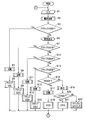
- FIG. 2 is a flowchart for explaining the operation of the vehicle steering system according to the embodiment of the present invention.
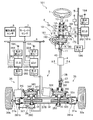
- FIG. 1A is a configuration diagram showing an outline of a vehicle steering system 101 according to an embodiment of the present invention.
- FIG. 1B is an internal configuration diagram of the first to third control devices 354, 363, and 393 which the vehicle steering system 101 has.
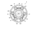
- FIG. 2 is an arrow cross-sectional view taken along the line AA, which shows the separated state of the coupling device 4.
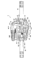
- FIG. 3 is a longitudinal cross-sectional view showing the disconnection state of the connection device 4.
- FIG. 4 is a cross-sectional view taken along line AA showing the coupled state of the coupling device 4.
- FIG. 5 is a longitudinal sectional view showing the coupled state of the coupling device 4.
- a vehicle steering apparatus 101 includes a steering wheel (steering wheel) 1, a reaction force application device 2, a steering device 3, and a coupling device 4, for example CAN (Controller Area).
- a communication medium 5 such as a network
- a vehicle speed sensor 6 for detecting the speed (vehicle speed) of a vehicle
- a yaw rate sensor 7 for detecting the speed (vehicle speed) of a vehicle
- a yaw rate sensor 7 for detecting the speed (vehicle speed) of a vehicle
- a yaw rate sensor 7 for detecting the speed (vehicle speed) of a vehicle
- a yaw rate sensor 7 for detecting the speed (vehicle speed) of a vehicle
- a yaw rate sensor 7 for detecting the speed (vehicle speed) of a vehicle
- a yaw rate sensor 7 for detecting the speed (vehicle speed) of a vehicle
- a yaw rate sensor 7
- the steering handle 1 corresponding to the "steering member" of the present invention is used to change the traveling direction of the vehicle (not shown) into a desired direction.
- a steering shaft 10 is connected to a central portion of the steering handle 1.
- the reaction force application device 2 has a function of applying a reaction force in the rotational direction of the steering shaft 10.
- the steering shaft 10 is connected to a second rotation shaft 40 of a connecting device 4 described later via a first universal joint 11.
- the steering shaft 10 is rotatably supported by first to third bearings 13, 14 and 15 provided at intervals in the interior of the case 12. The inside of the case 12 is kept liquid tight.
- the steering shaft 10 is provided with a steering torque sensor 16, a steering angle sensor 17, and a reaction force generator 18.
- the steering torque sensor 16 has a function of detecting the magnitude and direction of the steering torque input from the steering wheel 1 using, for example, solenoid type coils 12a and 12b.
- the steering torque signals SA and SB detected as changes in magnetic permeability by the coils 12a and 12b have mutually opposite characteristics (the added value of the steering torque signals SA and SB is constant).
- the steering torque signals SA and SB are input to the interface circuit 164.
- the waveforms of the steering torque signals SA and SB are shaped by amplification and filtering.
- the steering torque signals SA and SB after waveform shaping are input to a first control device 353, a second control device 363, and a third control device 393, which will be described later, via the communication medium 5.
- the first to third control devices 353, 363, and 393 calculate the sum of the steering torque signals SA and SB.
- the addition value of the steering torque signals SA and SB always takes a constant value when the steering torque sensor 16 is normal. This is because the steering torque signals SA and SB detected by the steering torque sensor 16 have mutually opposite characteristics. This means that the abnormality diagnosis of the steering torque sensor 16 can be performed based on whether or not the addition value of the steering torque signals SA and SB takes a constant value.
- any one of the steering torque signals SA and SB fluctuates rapidly, there is a high probability that coil breakage or circuit component abnormality has occurred.
- the first to third control devices 353, 363, and 393 monitor the torque torque sensor 16 for abnormality diagnosis by monitoring the time change of the added value of the steering torque signals SA and SB or the individual value of each. An abnormality diagnosis related to whether or not a break in the coil or an abnormality in a circuit component has occurred can be performed.
- the steering angle sensor 17 has a function of detecting a steering angle and a direction input from the steering wheel 1 using, for example, a pair of rotation angle sensors (not shown) such as two potentiometers. More specifically, the steering shaft 10 is provided with a small gear 174 rotatably around the steering shaft 10, as shown in FIG. 1A. In the small gear 174, a large gear 175 meshing with the small gear 174 is provided side by side.
- the pair of rotation angle sensors housed in the case 173 detect the rotation angles of the large gear 175, respectively, to thereby reduce the rotation angle signals SC and SD (both equivalent signals) related to the steering of the steering handle 1 decelerated. Output.
- the rotation angle signals SC and SD are input to a first control device 353, a second control device 363, and a third control device 393 described later via the communication medium 5, respectively.
- the first to third control devices 353, 363, and 393 have a function of performing an abnormality diagnosis related to whether or not the steering angle sensor 17 is abnormal by monitoring the comparison result of the rotation angle signals SC and SD.
- the rotation angle signals SC and SD have a common characteristic. This means that an abnormality diagnosis relating to whether or not the steering angle sensor 17 is abnormal can be performed based on whether or not the comparison results of the rotation angle signals SC and SD coincide with each other.
- the first to third control devices 353, 363, and 393 may perform an abnormality diagnosis related to whether or not the steering angle sensor 17 is abnormal by monitoring the comparison result of the rotation angle signals SC and SD. it can.
- the reaction force generator 18 has a function of generating a reaction force in the rotation direction of the steering shaft 10 of the steering wheel 1.
- the reaction force generating device 18 is provided on the third worm wheel 180 provided to be shared with the steering shaft 10 and on the rotation shaft of the third motor 181, and is engaged with the third worm wheel 180.
- the third control device 393 is provided with a third current sensor (third current detection unit) 181A that detects a third current value flowing to the third motor 181.
- the third current value detected by the third current sensor 181A is sent by the third control device 393 to the first control device 353 and the second control device 363 via the communication medium 5, respectively.
- the third control device 393 will be described in detail later, the third control device 393 for steering described later based on the steering torque signals SA and SB of the steering torque sensor 16 and the rotation angle signals SC and SD of the steering angle sensor 17. It has a function of generating control signals for driving and controlling the first motor 332, the second motor 342, and the third motor 181 for applying a steering reaction force.
- the third control device 393 may be configured without the function of generating a control signal for driving and controlling the first motor 332 or the second motor 342.
- the steering device 3 meshes with a rack shaft 32 connected to a pair of steered wheels 30a and 30b in the vehicle width direction via tie rods 31a and 31b, and a first rack tooth 320 provided on the rack shaft 32.
- the first gear shaft 330 is connected via a second universal joint 37 to one first rotation shaft 38 extending from the connecting device 4.
- the other second rotary shaft 40 extending from the coupling device 4 is connected to the steering shaft 10 via a first universal joint 11. Details of the configuration of the coupling device 4 will be described later.
- a pair of rack position sensors 39 for detecting the position of the rack shaft 32 in the axial direction is provided between one side of the rack shaft 32 (left side as viewed in the drawing) and the housing 380 covering components such as the rack shaft 32. It is provided.
- the rack position sensor 39 is configured by providing a pair of sensors (not shown) such as two potentiometers in a case 390, for example. Position detection signals of the pair of rack position sensors 39 are directly sent to the first to third control devices 353, 363, and 393 via the communication medium 5, respectively. Further, the first control device 353 sends the position detection signal of one of the pair of rack position sensors 39 to the second control device 353 and the third control device 363 via the communication medium 5, respectively. It is also good.
- the second control device 363 sends the other position detection signal of the pair of rack position sensors 39 to the first control device 353 and the third control device 393 via the communication medium 5. It is also good.
- the opening of the housing 380 is held fluid tight by the combination of the dust seals 381 a and 381 b and the oil seal 382.
- the first drive device 35 includes a first worm wheel 331 and a first worm (not shown) engaged with the first worm wheel 331.
- the first gear shaft 330 provided with the first worm wheel 331 and the first pinion gear 33 is rotatably supported at three points with respect to the housing 380 via bearings 350, 351, 352.
- the first worm is provided on the rotation shaft of the first motor 332.
- the second drive device 36 is configured to include a second worm wheel 341 and a second worm (not shown) engaged with the second worm wheel 341.
- a second gear shaft 340 provided with a second worm wheel 341 and a second pinion gear 34 is rotatably supported at three points relative to the housing 380 via bearings 360, 361, 362.
- the second worm is provided on the rotation shaft of the second motor 342.
- the rack shaft 32, the first pinion gear 33, the second pinion gear 34, the first drive device 35, and the second drive device 36 are the "steering force transfer mechanism" according to the present invention (claim 1). Equivalent to.
- the first control device 353 is provided with a first current sensor (first current detection unit) 332A that detects a first current value flowing to the first motor 332.
- the first current value detected by the first current sensor 332A is sent by the first controller 353 to the first controller 353 and the third controller 393 via the communication medium 5, respectively.
- the first controller 353 includes an interface circuit for data input / output, a computer for control calculation, a watchdog timer circuit for abnormality diagnosis, and an FET bridge circuit for driving the first motor 332 (all are not It is comprised including illustration etc.
- the first controller 353 is also connected to the power supply 184 through a series circuit of a fuse (not shown) and a first parent relay 354. Further, the first control device 353 is connected to the first motor 332 via the first slave relay 355. Therefore, the first control device 353 performs control to open the contacts of the first parent relay 354 and the first child relay 355, for example, at the time of abnormality diagnosis of the first current sensor 332A.
- the power supply to the first motor 332, the first control device 353, and the coupling device 4 is reliably cut off.
- the first control device 353 calculates the target position of the rack shaft 32, and the current position of the rack shaft 32 detected by the rack position sensor 39. Feedback control is performed so that the position matches the target position of the rack shaft 32 obtained by calculation.
- the first control device 353 (and the second control device 363 and the third control device 393) having the “abnormality diagnosis unit” of the present invention is detected by the first current sensor 332A.
- First current value and a second current value detected by a second current sensor 342A described later, and whether or not the deviation between the first and second current values exceeds a predetermined threshold value. Determine if
- the first motor 332 and the second motor 342 have their electrical characteristics set to be common to each other, in other words, the reduction ratio or the like so that the electrical characteristics are the same in the normal operating range.
- the processing in the control device is appropriately set, and the rotation shafts of the first motor 332 and the second motor 342 are mutually connected via the above-mentioned “steering force transmission mechanism”. .
- the first control device 353 does not require complicated diagnosis processing or waiting time, and the first motor 332 or the second motor Abnormality diagnosis of the motor 342 and their drive circuits (the first control device 353 and the second control device 363) can be promptly performed.
- the rack position sensor 39 is abnormal (when one of the pair of sensors 39 fails)
- the deviation of the first current value and the second current value does not occur without moving the rack shaft 32. Since this value becomes large, abnormality diagnosis of the rack position sensor 39 can be performed by monitoring this value. In short, the abnormality diagnosis of the rack position sensor 39 can be performed promptly without moving the steering wheels 30a and 30b.
- the abnormality diagnosis function of the first current sensor 332A or the second current sensor 342A included in the first control device 353 also includes the second control device 363 and the third control device 393 as well. It is configured.
- the first control device 353 When it is determined that at least one of the first current sensor 332A and the second current sensor 342A is abnormal, the first control device 353 performs control to cut off the power supply to the connecting device 4. Do. Thereby, the pair of first rotating shaft 38 and the second rotating shaft 40 extending from the connecting device 4 are mechanically connected, thereby mechanically connecting the steering shaft 10 and the first rotating shaft 38. .
- the first control device 353 does not energize the connecting device 4 when it is judged that at least one of the first current sensor 332A and the second current sensor 342A is abnormal.
- the second control device 363 determines that the second parent relay 364 is diagnosed when it is determined that at least one of the first current sensor 332A and the second current sensor 342A is abnormal.
- the power supply to the second motor 342 and the second control device 363 is reliably cut off by performing control to open the contacts of the second child relay 365 and the connection to the connection device 4.
- the power supply is interrupted by a relay (not shown) and the first rotary shaft 38 and the second rotary shaft 40 are connected.
- the third control device 393 functioning as a part of the reaction force generating device 18 in the normal state operates the steering function mode representing the setting state of the steering function as the electric power steering (Electric Power Steering: hereinafter) Control is performed so as to execute (continue) EPS assist control that reduces the steering torque of the steering wheel 1 (refer to Table 1).
- the second control device 363 is provided with a second current sensor (second current detection unit) 342A that detects a second current value flowing to the second motor 342. It is done.
- the second current value detected by the second current sensor 342A is sent by the second controller 363 to the first controller 353 and the third controller 393 via the communication medium 5, respectively.
- the second controller 363 drives an interface circuit for data input / output, a computer for control calculation, a watchdog timer circuit for abnormality diagnosis, and a second motor 342. In order to do that, it includes an FET bridge circuit (not shown).
- the second controller 363 is also connected to the power supply 184 via a series circuit of a fuse (not shown) and a second parent relay 364. Further, the second controller 363 is connected to the second motor 342 via the second slave relay 365. Therefore, the second control device 363 is, for example, at the time of abnormality diagnosis at the time when the deviation of the signals of the first current sensor 332A and the second current sensor 342A exceeds the predetermined threshold value due to the failure of the second motor 342. Power supply to the second motor 342, the second control device 363, and the connecting device 4 by performing control to open the contacts of the second parent relay 364 and the second child relay 365. The relay is operated by a relay (not shown) to connect the first rotating shaft 38 and the second rotating shaft 40.
- the second control device 363 calculates the target position of the rack shaft 32, and the current position of the rack shaft 32 detected by the rack position sensor 39. Feedback control is performed so that the position matches the target position of the rack shaft 32 obtained by calculation.
- the second control device 363 determines the difference between the first current value detected by the first current sensor 332A and the second current value detected by the second current sensor 342A. Is determined by calculation, and it is determined whether or not the difference between the determined first and second current values exceeds a predetermined threshold value.
- a predetermined threshold value For the premise that the characteristics of the first motor 332 and the second motor 342 are commonly set, when the required steering processing is normally performed, the first motor 332 and the second motor 332 are used. A substantially balanced current flows through each of the motors 342 in FIG. The reason is the same as above.
- the second control device 363 Based on the determination result regarding whether the difference between the first and second current values exceeds the threshold value, the second control device 363 generates a signal of the first current sensor 332A or a second current sensor. It can be understood that an abnormality diagnosis relating to whether or not at least one of the signals 342A is abnormal can be performed.
- the second control device 363 monitors the determination result as to whether or not the difference between the first and second current values exceeds the threshold value, thereby the signal of the first current sensor 332A or the second An abnormality diagnosis relating to whether or not at least one of the signals of the current sensor 342A is abnormal can be performed.
- the second control device 363 determines that a relay (not shown) is used. Thus, control is performed to cut off the power supply to the connecting device 4. Thereby, the pair of first rotating shafts 38 and the second rotating shaft 40 extending from the connecting device 4 are connected, and thereby the steering shaft 10 and the first rotating shaft 38 are connected.
- the second control device 363 is configured to determine whether at least one of the signal of the first current sensor 332A or the signal of the second current sensor 342A is abnormal. By performing control to open the respective contacts of the 2nd parent relay 364 and the 2nd child relay 365, power supply to the 2nd motor 342 and the 2nd control device 363 is cut off surely. Operate.
- the first control device 353 diagnoses that at least one of the signal of the first current sensor 332A or the signal of the second current sensor 342A is abnormal. , And performs control to open the respective contacts of the first parent relay 354 and the first child relay 355, thereby reliably interrupting the power supply to the first motor 332 and the first control device 353. To work.
- the third control device 393 functioning as a part of the reaction force generating device 18 in the normal state reconstructs the steering function mode representing the setting state of the steering function into the EPS function and steers it.
- Control is performed to execute (continue) EPS assist control that reduces the steering torque of the steering wheel 1 (see Table 1).
- ⁇ indicates a steering function mode (VGS1 in this example) set by rebuilding the steering system when there is a single failure, for example, when only the steering torque sensor 16 fails.
- “o” in Table 1 is set by rebuilding the steering system at the time of multiple failures, that is, for example, when the third current sensor 181A or the yaw rate sensor 7 fails after the steering torque sensor 16 fails.
- Steering function mode in this example, VGS.
- x of Table 1 shows various sensors 6, 7, 8, 16, 17, 39, 332A, 342A, 181A, or the 1st-3rd motors 332, 342, 181, the 1st-the 3rd
- a steering function mode which can not be set is shown by rebuilding of the steering system.
- the third control device 393 is a vehicle speed signal of the vehicle speed sensor 6, a signal of the yaw rate sensor 7, a signal of the lateral acceleration sensor 8, a signal of the steering torque sensor 16, a signal of the steering angle sensor 17, a signal of the rack position sensor 39, etc. , And mainly functions to drive and control the third motor 181.
- the third control device 393 makes an abnormality diagnosis by comparing the control signals generated by the first to third control devices 353, 363, and 393, identifies an abnormality diagnosis location, and identifies it.
- the steering system is rebuilt in consideration of eliminating the need for the abnormality diagnosis point, and as described in detail later, it operates to select an appropriate steering function mode and perform necessary control.
- the third control device 393 includes an interface circuit for data input / output, a computer for control calculation, a watchdog timer circuit for abnormality diagnosis, and an FET bridge circuit for driving the third motor 181. (All are not shown) etc. are comprised.
- the third controller 393 is connected to the power supply 184 via a series circuit of a fuse (not shown) and a third parent relay 185. Furthermore, the third control device 393 is connected to the third motor 181 via the third slave relay 186. Therefore, for example, in the case where it is determined that both the steering torque sensor 16 and the steering angle sensor 17 are abnormal, the third control device 393 determines that the third parent relay 185 and the third child relay 186 By performing control to open the respective contacts, power supply to the third motor 181, the third control device 393, and the connecting device 4 is reliably cut off. In this case, the third control device 393 couples the first rotating shaft 38 and the second rotating shaft 40 by the connecting device 4 and connects the steering shaft 10 and the first rotating shaft 38 to perform steering. Set the function mode to manual steering. However, when the third control device 393 is made to function as a general control device for the entire steering system, the configurations of the third parent relay 185 and the third child relay 186 can be omitted.
- the third control device 393 responds to the steering angle and the direction based on the rotation angle signals SC and SD of the steering angle sensor 17 Control is performed to cause the third motor 181 to generate a steering reaction force.
- a warning is displayed, and control is performed to make the steering torque larger (heavy) compared to that in the normal state.
- the third control device 393 calculates the third target current value to be supplied to the third motor 181, and the third current value detected by the third current sensor 181A is determined by calculation. The feedback control is performed to match the third target current value.
- the third control device 393 determines the third target current value obtained by the calculation as the terminal voltage signal of the third motor 181. And control is performed using the voltage signal after the conversion. During this control, a warning is displayed to notify the driver that an abnormality occurs in the signal of the third current sensor 181A, and the steering torque is made larger (heavy) compared to the normal time. Take control.
- the steering angle and direction based on the rotation angle signals SC and SD of the steering angle sensor 17 And while referring to the current position of the rack shaft 32 detected by the rack position sensor 39, a warning display is provided to notify the driver that an abnormality has occurred, and this is larger than in normal steering (
- the first control device 353 and the second control device 363 are used to perform drive control of the first motor 332 and the second motor 342 so as to obtain the (slow response) gear ratio.
- the third control device 393 performs control to open the contacts of the third parent relay 185 and the third child relay 186 so that the third motor 181 and the third motor 181 The power supply to the control device 393 of 3 is cut off surely.
- the connecting device 4 has a first rotating shaft 38 (see FIGS. 3 and 5) connected to the side of the turning device 3 and a second rotating shaft 40 connected to the side of the reaction force applying device 2 (see FIG. And 2) switching between either the coupled state or the disconnected state).
- the first rotation shaft 38 is rotatably supported by the case 45 via a four-point contact bearing (which may be a double-row angular bearing) 381 as shown in FIGS. 3 and 5.
- the second rotation shaft 40 is rotatably supported by the case 45 via the bearing 401 and is also rotatably supported by the first rotation shaft 38 via the bearing 405.
- a substantially cylindrical recess 383 is provided on the side of the reaction force application device 2 in the first rotation shaft 38.
- a substantially cylindrical shaft portion 403 is provided on the tip end side of the second rotation shaft 40 facing the steering device 3.
- the shaft portion 403 of the second rotation shaft 40 is rotatably supported with respect to the first rotation shaft 38 via a bearing 405 provided in the recess 383 of the first rotation shaft 38.
- the coupling device 4 includes a cylindrical member 380 provided on the tip side of the first rotation shaft 38 toward the reaction force applying device 2 and a plurality of rollers 41 provided around the second rotation shaft 40 at intervals.
- a plurality of spring members 42 provided between the plurality of rollers 41 and a cam member 401 provided on the outer peripheral side of the second rotation shaft 40 are configured.
- the cylindrical member 380 is configured to have a substantially hat-shaped cross section that opens toward the side of the reaction force application device 2.
- the hat-shaped portion of the cylindrical member 380 has an inner diameter larger than the outer diameter of the second rotation shaft 40.
- the plurality of rollers 41 are provided on the inner peripheral side of the cylindrical member 380 and in contact with the outer peripheral side of the cam member 401.
- the plurality of rollers 41 are provided in pairs of three pairs of rollers (sometimes referred to as “pair rollers”) 41, in three sets (six).
- the plurality of spring members 42 are provided between the pair of rollers 41 so as to bias the pair of rollers 41 in a direction to separate them.
- the cam member 401 is formed in a substantially triangular prism shape with its apex portion chamfered so as to have three cam surfaces 407 orthogonal to the radial direction of the second rotation shaft 40. On each of the three cam surfaces 407 of the cam member 401, a pair of rollers 41 are provided in close contact from three sides.
- the coupling device 4 is provided with a switching device 44 (FIG. 3, FIG. See FIG. 5).
- the switching device 44 reciprocates the switching claw portion 43 along the axial direction of the second rotation shaft 40 with respect to the cylindrical member 380 to obtain a combination of the cam member 401 and the three pairs of paired rollers 41 and a cylinder. It has a function of mechanically controlling the wedge-shaped engagement with the member 380.
- the switching device 44 urges a sleeve-like slider portion 440 capable of reciprocating along the axial direction on the outer peripheral portion of the second rotary shaft 40 and a direction for moving the slider portion 440 away from the cam member 401.
- an annular slider ring 442 rotatably supported on the outer peripheral portion of the slider portion 440.
- the movement of the slider ring 442 in the direction along the axial direction of the second rotation shaft 40 is restricted.
- three switching claw portions 43 are provided so as to be integrally extended toward the side of the steering device 3 at equal intervals in the circumferential direction. .
- the three switching claws 43 face the chamfered apex portions of the cam member 401 in a state in which the three switching claws 43 are inserted into the inner side of the cylindrical member 380 (see FIG. 2). It is arranged to fill the
- the slider ring 442 is integrally provided with a pair of pin members 443 along the radial direction of the second rotation shaft 40 at positions opposed to each other with the second rotation shaft 40 interposed therebetween.
- a lever member 444 having an annular portion is provided on the outer peripheral side of the slider ring 442.
- the metal case 45 is provided with a fulcrum 446 of a lever member 444.
- a rod member 447A is linked to a power point 447 of the lever member 444.
- the rod member 447A made of a magnetic material is detachably provided to the coil of the electromagnetic solenoid 448.
- a pair of elongated holes 445 extending in a direction orthogonal to the axial direction of the second rotation shaft 40 are provided at mutually opposing positions across the second rotation shaft 40. It has been established.
- a pair of pin members 443 are provided in the pair of long holes 445 of the lever member 444 so as to engage with each other. Thereby, the rotational movement of the lever member 444 about the fulcrum 446 is performed in the axial direction of the second rotation shaft 40 in the slider ring 442 via the pair of pin members 443 engaged with the pair of elongated holes 445. It is configured to act as a motion.
- a plurality of splines 449 extending in the axial direction of the second rotation shaft 40 are formed on the inner peripheral portion of the slider portion 440.
- a plurality of splines 450 extending along the axial direction is also formed on the second rotation shaft 40 facing the inner circumferential portion of the slider portion 440.
- the switching device 44 configured as described above operates as follows. That is, in the state where the coil of the electromagnetic solenoid 448 is magnetized by energization, as shown in FIG. 3, the rod member 447A is positioned in the insertion direction with respect to the coil of the electromagnetic solenoid 448. At this time, the lever member 444 rotates counterclockwise in accordance with the movement of the force point 447 connected to the rod member 447A. Then, the counterclockwise rotation movement of the lever member 444 about the fulcrum 446 moves toward the steering device 3 via the pair of pin members 443 engaged with the pair of elongated holes 445. Converted into an axial motion of 440.
- the slider portion 440 moves to the side of the steering device 3 against the elastic force of the spring member 441.
- the plurality of switching claw portions 43 are inserted into the inner side of the cylindrical member 380 so as to fill the gaps of the three pairs of paired rollers 41 (see FIG. 2).
- each of the three pairs of rollers 41 is pushed in the circumferential direction by the wedge-shaped side portions of the three switching claws 43.
- the plurality of spring members 42 respectively provided between the plurality of paired rollers 41 are in a state of being compressed.
- the first rotating shaft 38 and the second rotating shaft 40 are separated. Maintained. In this separated state, the first rotation shaft 38 and the second rotation shaft 40 are capable of relative rotation.
- the rod member 447A is positioned by the spring member 441 in the removal direction with respect to the coil of the electromagnetic solenoid 448.
- the lever member 444 rotates clockwise as the force point 447 connected to the rod member 447A moves.
- the clockwise rotation of the lever member 444 about the fulcrum 446 moves toward the side of the steering device 3 via the pair of pin members 443 engaged with the pair of elongated holes 445. Converted into axial motion of As a result, the slider portion 440 receives the elastic force of the spring member 441 and moves toward the reaction force application device 2.
- the electromagnetic solenoid 448 is magnetized only when all the drive signals of the electromagnetic solenoid 448 output from the first to third control devices 353, 363, and 393 are on (energized), but It operates to be demagnetized otherwise.
- each of the three pairs of rollers 41 functions as a resilient force of the plurality of spring members 42 respectively provided between the plurality of rollers 41.
- the distance between the pair of rollers 41 is greatly expanded to the set length of the spring member 42.
- each of the three pairs of pair rollers 41 is in close contact with the three cam surfaces 407 of the cam member 401.
- the third control device 393 for example, the locations of the steering torque sensor 16 etc.
- the diagnosis multiple failure
- the EPS is selected as the steering function mode
- the power supply to the connecting device 4 is cut off.
- the coil of the electromagnetic solenoid 448 is de-energized.
- the first rotary shaft 38 and the second rotary shaft 40 are switched from the disconnected state to the coupled state.
- the limit switch see FIGS. 3 and 5) 451, and the first to third via the communication medium 5. It is transmitted to the control devices 353, 363, and 393.
- the first to third control devices 353, 363, 393 diagnose, for example, an event that the switching claw 43 does not enter the inside of the cylindrical member 380 or the like by the signal of the limit switch 451, According to the result of the abnormality diagnosis, as shown in Table 1, the steering system is rebuilt. For example, when an abnormality diagnosis result indicating that the switching claw portion 43 does not enter the inside of the cylindrical member 380 is made, the first to third control devices 353, 363, 393 set the steering function mode to the EPS mode. And perform steering control.
- the switching claw portion of the connecting device is in the coupled state.
- an excessive load torque can be transmitted to the coupling portion of the coupling device 4 by setting the steering handle 1 stationary.
- the switching device 44 can not insert the plurality of switching claws 43 inward of the cylindrical member 380, and the connecting device 4 is disconnected from the coupled state It may not be possible to switch to the state.
- the switching device 44 smoothly smoothes the plurality of switching claws 43 inward of the cylindrical member 380. It corresponds so that it can be inserted. That is, the first to third control devices 353, 363, 393 drive the third motor 181 by driving at least one of the first motor 332 or the second motor 342 to achieve the coupling. The part is controlled to release the fixed state of the roller 41 and the cam surface 407. At the time of this drive control, by performing drive control in which the rotational directions of the first to third motors 332, 342, 181 are switched in an oscillating manner with an appropriate cycle, the above-mentioned coupled portion can be loosened. Good.
- FIG. 6 is a flowchart for explaining the operation of the vehicle steering system 101 according to the embodiment of the present invention.
- Table 1 shows various sensors 6, 7, 8, 16, 17, 39, 332A, 342A, 181A, and the first to third motors 332, 342, which are components of the vehicle steering system 101 according to the present invention.
- This map (as well as the map referred to below) is stored in the storage units 77a, 77b, 77c (see FIG. 1B) of the first to third control devices 353, 363, 393, respectively.
- step S1 the first to third control devices 353, 363, and 393 are connected via the communication medium 5 to the vehicle speed sensor 6, the yaw rate sensor 7, the lateral acceleration sensor 8, the steering torque sensor 16, the steering angle sensor 17, and the rack. Signals from various sensors including the position sensor 39 and the first to third current sensors 332A, 342A, and 181A are input.
- the first to third control devices 353, 363, and 393 execute abnormality diagnosis processing.
- the first to third control devices 353, 363, and 393 include various sensors 6, 7, 8, 16, 17, 39, 332A, 342A, 181A, and the first to third motors 332,
- Various functional units including 342, 181, and first to third control devices 353, 363, 393 diagnose whether or not there is an abnormality.
- abnormality diagnosis relating to the various sensors 6, 7, 8, 16, 17, 39, 332A, 342A, 181A, and the first to third motors 332, 342, 181, and the first to third Each diagnosis procedure will be specifically described separately from the abnormality diagnosis related to the control devices 353, 363, and 393.
- the first to third control devices 353, 363, 393 are respectively multiplexed (duplexed) Based on whether or not a pair of detection signals from various sensors being compared are matched with each other and they match (including the case where they converge within a predetermined tolerance range. The same applies hereinafter). Make a diagnosis as to whether the species is abnormal.
- the first to third control devices 353, 363, and 393 exemplarily illustrate a pair of vehicle speed detection signals from the multiplexed (duplexed) pair of vehicle speed sensors 6 as an example. Based on whether they are compared and match each other, it is diagnosed whether the vehicle speed sensor 6 is abnormal or not.
- the abnormality diagnosis of the vehicle speed sensor 6 is performed by taking in the signal of the engine rotational speed from another system (for example, PGM-FI: ProGraMmed Fuel Injection) other than the vehicle steering device 101 via the communication medium 5 and comparing. You may
- the first to third control devices 353, 363, and 393 each include a pair of first current sensors 332A that are multiplexed (duplexed) from the pair of first current sensors 332A.
- the current detection signals of 1 are compared with each other, and it is diagnosed whether or not the first current sensor 332A is abnormal based on whether or not they match.
- the first to third control devices 353, 363, and 393 receive the pair of second current detection signals from the second current sensor 342A and the pair of third current detection signals from the third current sensor 181A. Also perform the same abnormality diagnosis as described above.
- the first to third control devices 353, 363, and 393 may diagnose that one of the first current sensor 332A and the second current sensor 342A is abnormal.
- the first to third control devices 353, 363, and 393 compare the detection signal from the first current sensor 332A with the detection signal from the second current sensor 342A, and A configuration may be adopted in which a diagnosis that either one of the first current sensor 332A or the second current sensor 342A is abnormal is made based on whether or not they match. According to this configuration, since the abnormality diagnosis can be performed without multiplexing the current sensors 332A and 342A, the system configuration can be simplified.
- the abnormality diagnosis relating to the first to third motors 332, 342, 181 is, for example, the first motor based on the abnormality diagnosis result based on the binary comparison of the first and second current sensors 332A, 342A. Based on the result of comparing the drive command current value of the third motor and the signal of the third current sensor 181A, the third motor 181 has an abnormality while making a diagnosis that the motor 332 or the second motor is abnormal. It is sufficient to adopt a configuration that makes a diagnosis to that effect.
- the first to third control devices 353, 363, and 393 mutually execute results for processing contents common to each other in input and output.
- the control device having a high probability of occurrence of an abnormality is identified by comparing the three values. For example, in the case where the result for the common processing content is the same among all three (including the case where the convergence is within a predetermined tolerance range, the same applies hereinafter), all the first to third controls are performed according to the majority rule.
- the devices 353, 363, 393 are diagnosed as correct.
- the majority decision According to the principle, while the two diagnoses as correct, the other one diagnoses as wrong. And when the result with respect to the said common processing content differs between three parties, it diagnoses that all three parties are wrong.
- the first to third control devices 353, 363, and 393 refer to the map (Table 1) based on the diagnosis result as to whether or not all the sensors or functional parts in step S2 are normal. Select the steering function mode according to the result.
- the map (Table 1) an appropriate steering function mode for the type of abnormal point is described in association.
- the first to third control devices 353, 363, 393 operate the steering function mode Active Variable Gear ratio Steering (hereinafter referred to as "Active VGS") Set to).
- Active VGS Active Variable Gear ratio Steering
- the first to third control devices 353, 363, 393 refer to the map (Table 1) and perform appropriate steering function for the type of the abnormal place. Set the mode appropriately.
- step S3 when all the sensors or functional units are normal (Yes) in response to the diagnosis result of whether all the sensors or functional units in step S2 are normal (Yes), the first to third The controller 353, 363, 393 advances the process flow to the next step S4.
- step S3 if it is determined that the steering function mode should not be set to the active VGS mode as a result of the determination in step S3 (No), that is, any one or more of the sensors or functional units is abnormal.
- the first to third control devices 353, 363, and 393 cause the flow of processing to jump from the flow of processing to step S6.
- step S4 the first to third control devices 353, 363, and 393 supply the power to the electromagnetic solenoid 448 of the connecting device 4 to control the connecting device 4 to be in the disconnected state.
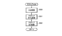
- step S5 the first to third control devices 353, 363, and 393 set the active VGS control to set the steering function mode to the active VGS mode (corresponding to the "first steering function mode" of the present invention). Then, the process flow is returned to step S1. The details of the active VGS control will be described later.
- step S6 If it is determined in step S6 that one or more of the sensors or the functional unit is abnormal as a result of the determination in step S3, the first to third control devices 353, 363, and 393 Control is performed to turn on an alarm lamp provided on an instrument panel (not shown) of the vehicle and to display an abnormality diagnosis point.
- the first to third control devices 353, 363, and 393 reconstruct the steering system in accordance with the result of the abnormality diagnosis in step S2, as will be described next, and perform appropriate steering function mode. Perform steering control by setting.
- step S7 the first to third control devices 353, 363, and 393 generate the abnormality diagnosis result (indicating that the steering torque sensor 16 is abnormal) in step S2 and the steering function mode map of Table 1 Referring to it, it is determined whether the steering function mode should be set to the active VGS1 mode. If it is determined that the steering function mode should be set to the active VGS 1 mode as a result of the determination in step S 7 (Yes), the first to third control devices 353 363 393 follow the flow of processing. Proceed to step S8 of.
- step S10 if it is determined that the steering function mode should not be set to the active VGS1 mode as a result of the determination in step S7 (No), the first to third control devices 353, 363, and 393 perform the processing of The flow jumps to step S10.
- step S8 the first to third control devices 353, 363, and 393 control the connection device 4 to be in the disconnected state by continuing the power supply to the connection device 4.
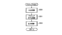
- step S9 the first to third control devices 353, 363, and 393 set the active VGS1 control to set the steering function mode to the active VGS1 mode (corresponding to the "first steering function mode" of the present invention). Then, the process flow is returned to step S1. The details of the active VGS1 control will be described later.
- step S10 the first to third control devices 353, 363, 393 activate the steering function mode with reference to the result of the abnormality diagnosis (indicating that the third current sensor 181A is abnormal) in step S2 VGS2 It is determined whether the mode should be set. If it is determined that the steering function mode should be set to the active VGS 2 mode as a result of the determination in step S10 (Yes), the first to third control devices 353, 363, and 393 follow the flow of the process. The process proceeds to step S11.
- step S10 determines that the steering function mode should not be set to the active VGS2 mode as a result of the determination in step S10 (No)
- the first to third control devices 353, 363, and 393 perform the processing of The flow is jumped to step S13.
- step S11 the first to third control devices 353, 363, and 393 control the connection device 4 to be in the disconnected state by continuing the power supply to the connection device 4.
- step S12 the first to third control devices 353, 363, 393 set the active VGS 2 control to set the steering function mode to the active VGS 2 mode (corresponding to the "first steering function mode" of the present invention). Then, the process flow is returned to step S1. The details of the active VGS2 control will be described later.
- step S13 the first to third control devices 353, 363, 393 diagnose the abnormality in step S2 (indicating that the third motor 181 or the third control device (third ECU) 393 is abnormal). With reference to the result, it is determined whether or not the steering function mode should be set to the active VGS3 mode. If it is determined that the steering function mode should be set to the active VGS 3 mode as a result of the determination in step S13 (Yes), the first to third control devices 353, 363, and 393 follow the flow of the process. Proceed to step S14 of.
- step S13 if it is determined that the steering function mode should not be set to the active VGS 3 mode as a result of the determination in step S13 (No), the first to third control devices 353, 363, and 393 perform the processing of The flow is jumped to step S16.
- step S14 the first to third control devices 353, 363, and 393 control the connection device 4 to be in the disconnected state by continuing the power supply to the connection device 4.
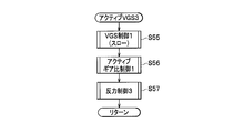
- step S15 the first to third control devices 353, 363, and 393 set the active VGS 3 control to set the steering function mode to the active VGS 3 mode (corresponding to the "first steering function mode" of the present invention). Then, the process flow is returned to step S1.
- the active VGS 3 control will be described later in detail.
- step S16 the first to third control devices 353, 363, 393 refer to the abnormality diagnosis result (indicating that the yaw rate sensor 7 or the lateral acceleration sensor 8 is abnormal) in step S2 to select the steering function mode. It is determined whether the VGS mode should be set. If it is determined that the steering function mode should be set to the VGS mode as a result of the determination in step S16 (Yes), the first to third control devices 353, 363, and 393 follow the flow of processing. Proceed to step S17.
- step S16 if it is determined that the steering function mode should not be set to the VGS mode as a result of the determination in step S16 (No), the first to third control devices 353, 363, and 393 perform the process flow Is jumped to step S19.
- step S17 the first to third control devices 353, 363, and 393 control the connection device 4 to be in the disconnected state by continuing the power supply to the connection device 4.
- step S18 the first to third control devices 353, 363, and 393 perform VGS control to set the steering function mode to the VGS mode (corresponding to the "second steering function mode" of the present invention), Thereafter, the process flow is returned to step S1.
- VGS control The details of the VGS control will be described later.
- step S19 the first to third control devices 353, 363, and 393 control the switching of the connecting device 4 from the disconnected state to the connected state by interrupting the power supply to the electromagnetic solenoid 448 of the connecting device 4. I do.
- step S20 the first to third control devices 353, 363, 393 perform the operations in step S2 (steering angle sensor 17, rack position sensor 39, first current sensor 332A, second current sensor 342A, first The motor 332, the first control unit (first ECU) 353, the second motor 342, the second control unit (second ECU) 363, or the connection device 4 is abnormal
- it is determined whether the steering function mode should be set to the EPS mode it is determined whether the steering function mode should be set to the EPS mode.
- the normal control device among the first to third control devices 353, 363, and 393 is The process flow proceeds to the next step S21.
- step S20 determines that the steering function mode should not be set to the EPS mode as a result of the determination in step S20 (No)
- the first to third control devices 353, 363, and 393 perform the process flow Is jumped to step S22.
- step S21 the normal control device among the first to third control devices 353, 363, 393 corresponds to the electric power steering (EPS) mode (the "third steering function mode" of the present invention) in the steering function mode.
- EPS electric power steering
- step S22 the first to third control devices 353, 363, and 393 set the steering function mode to the manual steering mode (corresponding to the "fourth steering function mode" of the present invention). Then, the process flow is returned to step S1.
- the manual steering control will be described later in detail.
- FIG. 7 is a flowchart showing the flow of processing of a subroutine program related to the active VGS.
- step S50 the first to third control devices 353, 363, and 393 use the signals of the steering angle sensor 17, the rack position sensor 39, and the vehicle speed sensor 6 to determine the steering angles based on the signals of the steering angle sensor 17.
- the gear ratio between the steering wheel turning angle based on the signal of the rack position sensor 39 is variably set according to the vehicle speed signal of the vehicle speed sensor 6, and the steering wheel turning angle realizing the thus set gear ratio
- the drive control of the first and second motors 332 and 342 is performed so that the current position of the rack shaft 32 follows.
- Such drive control of the first and second motors 332 and 342 is referred to as "VGS control".
- the first to third control devices 353, 363, and 393 refer to a map in which an appropriate gear ratio is set in advance according to a change in the vehicle speed. Read out and set the gear ratio (VGS ratio) according to your requirements.
- VGS ratio is set to, for example, a quick ratio which becomes 1 or less in the low vehicle speed region, that is, a gear ratio in which the steered wheel turning angle becomes larger than the actual steering angle.
- the steering wheel turning angle is set to a slow ratio which becomes a value of 1 or more, that is, a gear ratio in which the steering wheel turning angle becomes smaller than the actual steering angle.
- the first to third controls are made so that the current position of the rack shaft 32 follows the position of the rack shaft 32 corresponding to the steered wheel turning angle that achieves the gear ratio (VGS ratio) thus set.
- the devices 353, 363, and 393 perform drive control of the first and second motors 332, 342.
- the gear ratio (VGS ratio) is appropriately set in consideration of the fact that the yaw rate of the vehicle matches a predetermined steady state value and that the lateral acceleration of the vehicle body does not exceed a predetermined limit value.
- the first and second current values respectively flowing through the first and second motors 332 and 342 correspond to the first and second motors 332 and 342, and
- the first and second control devices 353 and 363 and the first and second drive devices 35 and 36 are normal, they are determined mainly based on the load (friction coefficient) of the road surface.
- the first and second motors 332 and 342, the first and second control devices 353 and 363, the first and second drive devices 35 and 36, etc. are abnormal, specifically, for example, When the one-phase winding of the first motor 332 is shorted, the current of the first motor 332 is increased. Therefore, each of the first to third control devices 353, 363, and 393 monitors, via the communication medium 5, whether such an event (current increase of the first motor 332) has occurred. The first and second current values thus monitored are used when making an abnormality diagnosis of the first and second current sensors 332A, 342A, or when making an abnormality diagnosis of the first and second control devices 353, 363. And so on.
- step S51 the first to third control devices 353, 363, and 393 use the signals from the steering angle sensor 17, the rack position sensor 39, the yaw rate sensor 7, and the lateral acceleration sensor 8 to output signals from the yaw rate sensor 7.
- Active gear ratio control that actively controls the gear ratio (VGS ratio) independently of the steering angle, based on the vehicle yaw rate based on the vehicle and the lateral acceleration of the vehicle body based on the signal of the lateral acceleration sensor 8 I do. This stabilizes the behavior of the vehicle.
- the first to third control devices 353, 363, and 393 are appropriate in accordance with the steering angle based on the signal of the steering angle sensor 17 and the change of the steering angle.
- the reference (target) yaw rate and reference (target) lateral acceleration according to the current steering angle are read out and set by referring to a map in which the yaw rate and the lateral acceleration are preset, and the reference (target) value thus set is set.
- the first and second motors 332 and 342 are feedback-controlled so that the yaw rate of the vehicle and the lateral acceleration of the vehicle follow.
- the first to third control devices 353, 363, 393 control the vehicle to travel straight by automatically correcting the turning angles of the steering wheels 30a, 30b.
- the first to third control devices 353, 363, 393 mechanically perform gear ratio control in VGS control, but in active gear ratio control, the driver's operation is automatically corrected finely for external disturbance factors.
- a steering intention from the directional steering wheel 1 is designated as a steering wheel command (Handle Command), and control is performed to appropriately steer the steered wheel turning angle independently of the steering angle by the steering wheel 1.
- the first to third control devices 353, 363, and 393 are signals of the steering torque sensor 16, the steering angle sensor 17, the vehicle speed sensor 6, the yaw rate sensor 7, and the lateral acceleration sensor 8, and the steering torque.
- the setting table a table in which an appropriate steering torque is set in advance corresponding to each detection signal of the steering torque sensor 16, the steering angle sensor 17, the vehicle speed sensor 6, the yaw rate sensor 7, and the lateral acceleration sensor 8)
- the steering torque becomes large (heavy) according to the increase of the steering angle sensor detection signal, the yaw rate detection signal and the lateral acceleration detection signal, and the steering torque becomes large (heavy) according to the increase of the vehicle speed.
- the current steering torque based on the signal of the steering torque sensor 16 is set to the above-mentioned target steering torque.
- Such feedback control is called "active reaction force control”.
- active reaction force control By providing an appropriate response when operating the steering handle 1, the self aligning torque of the vehicle can be increased, and the vehicle can be guided in the stable direction.
- the steering wheel 30a and 30b are returned as if the driver naturally steers in the stable direction by simply putting the hand on the steering wheel 1 as a result (self-aligning torque). The operability of can be improved.
- the first to third control devices 353, 363, and 393 set in advance appropriate steering torque in accordance with the vehicle speed signal of the vehicle speed sensor 6 and changes in the vehicle speed.
- the map it is controlled to set the response of the steering wheel 1 small in the low vehicle speed region, and set the response of the steering wheel 1 large in the high vehicle speed region. Therefore, according to the steering angle of the steering wheel 1, or according to the yaw rate or the lateral acceleration, the response of the steering wheel 1 is appropriately set by taking into consideration the vehicle speed signal of the vehicle speed sensor 6, Thus, the operability of the steering handle 1 can be improved.
- the detection signal of the yaw rate sensor 7 increases and the steering reaction force is large, that is, the response is controlled to be heavy, so the self aligning torque is increased to stop the spin.
- the steering handle 1 is made easy to operate. As described above, by changing the response related to the operation direction of the steering handle 1, the driver can be urged to operate the steering handle 1 appropriately. Furthermore, in principle, there is no mechanical connection between the steering wheel 1 and the steering wheels 30a, 30b, so that the kickback due to the vibration of the traveling road surface or the step difference, the driving power difference between the steering wheels 30a, 30b Torque steer based on (front wheel drive vehicle) can be eliminated.
- step S52 When the active reaction force control in step S52 ends, the first to third control devices 353, 363, and 393 return the flow of processing to step S1 in FIG. 6, and sequentially execute the following processing.
- FIG. 8 is a flowchart showing the flow of processing of a subroutine program related to the active VGS 1.
- Common processing steps S50 and S51
- Common processing steps S50 and S51
- the description of these common processing steps S50 and S51
- the difference between the two step S53
- the first to third control devices 353, 363, and 393 that have made an abnormality diagnosis that the steering torque sensor 16 has an abnormality in step S53 are the steering angle sensor 17, the vehicle speed sensor 6, the yaw rate sensor 7, and , And appropriate steering torque corresponding to each signal detected by the steering acceleration setting table (steering angle sensor 17, vehicle speed sensor 6, yaw rate sensor 7, and lateral acceleration sensor 8) are set in advance.
- the steering torque on the steering wheel 1 becomes large (heavy) according to the increase of the steering angle sensor detection signal, the yaw rate detection signal, and the lateral acceleration detection signal with reference to the table).
- the steered vehicle that is the target according to the increase of the steering angle sensor detection signal, the yaw rate detection signal and the lateral acceleration detection signal
- the voltage is called "reaction force control 1”.
- the steered wheels 30a, 30b would be returned as if they were naturally steered in the stable direction (self-aligning torque) as a result of the self-alignment of the vehicle
- the lining torque can be increased, the stability of the vehicle can be imparted, and the operability of the steering handle 1 can be improved.
- the first to third control devices 353, 363, and 393 set in advance appropriate steering torque in accordance with the vehicle speed signal of the vehicle speed sensor 6 and the change of the vehicle speed.
- the response of the steering wheel 1 is set small in the low vehicle speed range, while the response of the steering wheel 1 is set large in the high vehicle speed range. Therefore, according to the steering angle of the steering wheel 1, or according to the yaw rate or the lateral acceleration, the response of the steering wheel 1 is appropriately set by taking into consideration the vehicle speed signal of the vehicle speed sensor 6, Thus, the operability of the steering handle 1 can be improved.
- the first to third control devices 353, 363, and 393 perform warning display notifying that the steering torque sensor 16 is abnormal, and make the steering torque larger than that in the normal state ( Do heavy control. As a result, the driver is notified in a timely manner that an abnormality has occurred in the steering system.
- step S53 When the reaction force control 1 in step S53 ends, the first to third control devices 353, 363, and 393 return the flow of processing to step S1 in FIG. 6, and sequentially execute the following processing.
- FIG. 9 is a flowchart showing the flow of processing of a subroutine program related to the active VGS 2.
- Common processing steps S50 and S51
- Common processing steps S50 and S51
- the description of these common processing steps S50 and S51
- the difference between the two step S54
- the first to third control devices 353, 363, and 393 that have made an abnormality diagnosis that the third current sensor 181A is abnormal in step S54 are the steering torque sensor 16, the steering angle sensor 17, and the vehicle speed sensor 6, the signals of the yaw rate sensor 7 and the lateral acceleration sensor 8, and the steering torque setting table (for each of the detection signals of the steering torque sensor 16, the steering angle sensor 17, the vehicle speed sensor 6, the yaw rate sensor 7 and the lateral acceleration sensor 8)
- the steering torque increases (the response is heavy) according to the increase of the steering angle sensor detection signal, the yaw rate detection signal, and the lateral acceleration detection signal with reference to a table in which an appropriate steering torque is preset.
- the target steering torque is set so that the steering torque becomes large (the response becomes heavy) as the vehicle speed increases, and the current steering Torque as to follow the steering torque becomes the set target, using a differential signal of the steering angle sensor 17, controls the inter-terminal voltage of the third motor 181.
- Such control is called "reaction force control 2".
- the self aligning torque of the vehicle can be increased, and the vehicle can be guided in the stable direction.
- the steering wheels 30a, 30b would be returned as if they were naturally steered in the stable direction (as a result of the self aligning torque)
- the vehicle self The aligning torque can be increased, the stability of the vehicle can be provided, and the operability of the steering handle 1 can be improved.
- the first to third control devices 353, 363, and 393 set in advance appropriate steering torque in accordance with the vehicle speed signal of the vehicle speed sensor 6 and changes in the vehicle speed.
- the map it is controlled to set the response of the steering wheel 1 small in the low vehicle speed region, and set the response of the steering wheel 1 large in the high vehicle speed region. Therefore, according to the steering angle of the steering wheel 1, or according to the yaw rate or the lateral acceleration, the response of the steering wheel 1 is appropriately set by taking into consideration the vehicle speed signal of the vehicle speed sensor 6, Thus, the operability of the steering handle 1 can be improved.
- the first to third control devices 353, 363, and 393 display a warning to notify the abnormality of the third current sensor 181A, and also compare the steering torque with that in the normal state. Control to make large (weighted response). As a result, the driver is notified in a timely manner that an abnormality has occurred in the steering system.
- step S54 When the reaction force control 2 in step S54 ends, the first to third control devices 353, 363, and 393 return the flow of processing to step S1 in FIG. 6, and sequentially execute the following processing.
- FIG. 10 is a flowchart showing the flow of processing of a subroutine program related to the active VGS 3.
- the active VGS3 (step S15 in FIG. 6) indicates that the third motor 181 or the third control device (third ECU) 393 is abnormal, and the steering function mode is active in step S13 in FIG. This process is executed when it is determined that the mode should be set.
- the first or second control device 353 or 363 may appropriately control the response of the steering handle 1 Have difficulty. This is because the third motor 181 and the third control device (third ECU) 393 mainly play the role of providing a reaction force to the steering torque.
- the first or second control device 353 or 363 which has made an abnormality diagnosis that the third motor 181 or the third control device 393 has an abnormality in step S55 is shown in FIG.
- the VGS control 1 is performed according to the VGS control in step S50 shown in FIG. That is, in the VGS control 1 of step S55, the first or second control device 353, 363 uses the signals of the steering angle sensor 17, the rack position sensor 39, and the vehicle speed sensor 6 to obtain the gear ratio (VGS).
- the ratio is variably set to be a slow ratio as compared to the example of the VGS control in step S50, and a rack is set at the steering wheel turning angle that achieves the set gear ratio.
- the drive control of the first and second motors 332 and 342 is performed so that the current position of the shaft 32 follows.
- the responsiveness of the steered wheel turning angle to the operation amount of the steering handle 1 is reduced as compared to the example of the VGS control at step S50.
- the driver does not feel particularly uncomfortable despite the fact that the third motor 181 or the third control device (third ECU) 393 is abnormal.
- the vehicle's behavior as a whole can be controlled slowly.
- the first or second control device 353 or 363 which has made an abnormality diagnosis indicating that the third motor 181 or the third control device (third ECU) 393 is abnormal in step S56 is shown in FIG.
- Active gear ratio control 1 is performed according to the active gear ratio control of step S51. That is, in the active gear ratio control 1 in step S56, the first or second control device 353 or 363 uses signals of the steering angle sensor 17, the rack position sensor 39, the yaw rate sensor 7, and the lateral acceleration sensor 8. , Based on the yaw rate of the vehicle based on the signal of the yaw rate sensor 7 and the lateral acceleration of the vehicle based on the signal of the lateral acceleration sensor 8, independently of the steering angle, compared with the example of active gear ratio control in step S51. The above-mentioned gear ratio (VGS ratio) is actively controlled to achieve the slow ratio. This stabilizes the behavior of the vehicle.
- the first or second control device 353 or 363 determines a steering angle based on the signal of the steering angle sensor 17 and an appropriate yaw rate according to a change in the steering angle.
- the reference (target) yaw rate and the reference (target) lateral acceleration according to the current steering angle are read out and set by referring to a map in which the lateral acceleration is preset.
- the respective reference (target) values are set smaller (more gently) than in the example of the active gear ratio control at step S51.
- the first and second motors 332 and 342 are feedback-controlled so that the yaw rate of the vehicle and the lateral acceleration of the vehicle follow the reference (target) value set in this manner (mildly).
- the active gear ratio control 1 in step S56 the responsiveness of the steering wheel turning angle to the operation amount of the steering wheel 1 is reduced as compared with the example of the active gear ratio control in step S51.
- the driver has a particular feeling of strangeness despite the fact that the third motor 181 or the third control device (third ECU) 393 is abnormal. The behavior of the vehicle as a whole can be stabilized without causing
- the first or second control device 353 or 363 which has made an abnormality diagnosis indicating that the third motor 181 or the third control device (third ECU) 393 is abnormal in step S57 is shown in FIG.
- the reaction force control 3 is performed according to the active reaction force control of step S52. That is, in the reaction force control 3 of step S57, the first or second control device 353, 363 performs control to open the contacts of the third parent relay 185 and the third child relay 186, respectively.
- the power supply to the third motor 181 and the third controller 393 is shut off.
- the first or second control device 353 or 363 returns the flow of processing to step S1 in FIG. 6, and sequentially executes the following processing.
- FIG. 11 is a flowchart showing the flow of processing of a subroutine program related to VGS.
- a common processing step (S50) exists between the active VGS control shown in FIG. 7 and the VGS control shown in FIG. Therefore, the description of the common processing step (S50) will be omitted, and the processing of step S58 having only the VGS control shown in FIG. 11 will be described.
- the yaw rate sensor 7 or the lateral acceleration sensor 8 is abnormal, and it is determined in step S18 in FIG. 6 that the steering function mode should be set to the VGS mode. It is a process that is executed in the case.
- the first to third control devices 353, 363, and 393 that have made an abnormality diagnosis that the yaw rate sensor 7 or the lateral acceleration sensor 8 is abnormal in step S58 are reaction forces generally performed in the electric power steering (EPS).
- a reaction force control 4 similar to the control is performed. That is, in the reaction force control 4 in step S58, the first to third control devices 353, 363, and 393 control the steering torque based on the signal of the steering torque sensor 16 and an appropriate target current according to the change of the steering torque.
- the target current value given to each of the first to third control devices 353, 363, and 393 is set according to the current steering torque by referring to the map set in advance, and the target current value thus set is set.
- drive control of the first to third motors 332, 342 and 181 is performed so that the detection values of the first to third current sensors 332A, 342A and 181A follow.
- the first to third control devices 353, 363, 393 perform warning display indicating that the yaw rate sensor 7 or the lateral acceleration sensor 8 is abnormal, and Control is performed to make the steering torque larger (heavy) in comparison. As a result, the driver is notified in a timely manner that an abnormality has occurred in the steering system.
- step S58 When the reaction force control 4 in step S58 ends, the first to third control devices 353, 363, and 393 return the flow of processing to step S1 in FIG. 6, and sequentially execute the following processing.
- FIG. 12 is a flowchart showing the flow of processing of a subroutine program related to EPS.
- EPS (step S21 in FIG. 6) is the steering angle sensor 17, the rack position sensor 39, the first current sensor 332A, the second current sensor 342A, the first motor 332, the first control device (first ECU 353, second motor 342, second control device (second ECU) 363, or clutch (not shown) is abnormal, and the steering function mode is set in step S 21 of FIG. This process is executed when it is determined that the EPS mode should be set.
- step S59 the steering angle sensor 17, the rack position sensor 39, the first current sensor 332A, the second current sensor 342A, the first motor 332, the first control device (first ECU) 353, the second The first to third control devices 353, 363, and 393 that have made an abnormality diagnosis that any of the motor 342, the second control device (second ECU) 363, or the clutch is abnormal are electric power steering A reaction force control 5 similar to reaction force control generally performed in (EPS) is performed.
- EPS reaction force control 5 similar to reaction force control generally performed in
- the first to third control devices 353, 363, and 393 issue, for example, a signal of the limit switch 451 and a command signal for setting the connecting device 4 in the coupled state.
- the abnormality diagnosis of the coupling device 4 for example, although the command signal for putting the coupling device 4 in the coupled state is issued, the signal of the limit switch 451 is off (see FIG. 3) If it is determined that the time t) is lowered, the reaction force control 4 of step S58 is performed.
- the third control device 393 refers to a map in which a steering torque based on the signal of the steering torque sensor 16 and an appropriate target current corresponding to a change in the steering torque are preset. Then, the target current value of the third motor 181 according to the current steering torque is set, and the third motor 81 follows the detection value of the third current sensor 181 with respect to the target current value thus set. The drive control of 181 is performed.
- the third control device 393 performs a warning display to notify an abnormal part and performs control to make the steering torque larger (heavy) as compared with that in the normal state. As a result, the driver is notified in a timely manner that an abnormality has occurred in the steering system.
- step S59 When the reaction force control 5 in step S59 ends, the third control device 393 returns the flow of processing to step S1 in FIG. 6, and sequentially executes the following processing.
- FIG. 13 is a flowchart showing the flow of processing of a subroutine program related to manual steering.
- the steering function mode is the EPS mode shown in FIG. 12
- the manual steering is performed to either the third motor 3181 or the third control device (third ECU) 393.
- This processing is executed when it is determined in step S22 of FIG. 6 that the steering function mode should be set to the manual steering mode when an abnormality occurs.
- step S59 when the steering function mode is the EPS mode, an abnormality diagnosis is made that an abnormality has occurred in either the third motor 3181 or the third control device (third ECU) 393
- the second control devices 353 and 363 may include the first parent relay 354 and the first child relay 355, the second parent relay 364 and the second child relay 365, and the third parent relay 185 and the third relay.
- the power supply to the control device 393 of 3 and the connection device 4 is shut off, and all control functions of the first to third control devices 353, 363, and 393 are turned off. Thereby, the steering function mode is returned to the manual steering mode.
- the abnormality diagnosis units 79a, 79b, 79c included in the first to third control devices 353, 363, 393 are the first and second When the deviation of the first and second current values respectively detected by the current sensors 332A and 342A exceeds a predetermined threshold value, it is determined to make a diagnosis that the steering device 3 is abnormal.
- the abnormality diagnosis units 79a, 79b, and 79c of the first to third control devices 353, 363, and 393 only monitor deviations of the first current value and the second current value, which results in complicated arithmetic processing.
- the abnormality diagnosis of the steering device 3 can be performed without requiring the standby time due to the diagnosis processing. Therefore, according to the vehicle steering apparatus 101 according to the embodiment of the present invention, for example, when the steering motor or the like breaks down, an abnormal signal is generated in the first or second current detection unit. Also, the diagnosis of the occurrence of such an abnormality can be made promptly.
- the abnormality diagnosis units 79a, 79b, 79c directly detect the currents flowing through the first motor 332 and the second motor 342 for turning by the first and second current sensors 332A, 342A, respectively. Since the abnormality diagnosis is performed based on the first and second current values, the abnormality diagnosis can be made before the malfunctioning motor rotates abnormally at the time of the abnormality diagnosis, and the malfunctioning motor may appear due to the malfunctioning rotation. Anomalous behavior of a certain vehicle can be suppressed in advance. Regarding this, for example, temporarily, a three-phase motor is adopted as the first motor 332 and the second motor 342 for steering, and a failure example in which one of the three-phase motors is shorted and a large current flows is taken up. Explain.
- abnormality diagnosis can be performed instantaneously.
- the first motor 332 and the second motor 342 are set such that their electrical characteristics are common to each other. Therefore, the magnitude of the output of the normal motor is equal to the magnitude of the output of the abnormal motor, and the magnitude of the output of the abnormal motor overcomes the magnitude of the output of the normal motor. Will not be steered until an abnormal condition is reached.
- the other motor can maintain the turning function. Furthermore, even if an abnormality (reverse rotation) occurs in one of the first and second motors 332 and 342, the abnormality (reverse rotation) can be offset by the other motor. As a result, the effect of maintaining the turning function as much as possible can be expected.
- the first and second motors 332 and 342 for steering whose electric characteristics are set to be common to each other via the steering force transmission mechanism. Since they are connected to each other, the output characteristics of the individual motors can be suppressed to a low level as compared with the case of steering drive with a single motor. Therefore, for example, it is possible to operate by receiving power supply from an existing 12 volt capacity battery, and a new 24 volt capacity or 48 volt capacity booster circuit is not required. As a result, the size of each motor can be reduced, and the freedom of layout design can be secured.
- the abnormality diagnosis units 79a, 79b, 79c perform abnormality diagnosis in accordance with the principle of majority decision. That is, the abnormality diagnosis units 79a, 79b, and 79c of the first to third control devices 353, 363, and 393 are obtained by the first to third control devices 353, 363, and 393 executing common processing, respectively. Control device corresponding to the two or more processing results when two or more processing results among the three processing results fall within a predetermined allowable range based on the comparison result While making a diagnosis that the controller is normal, while making a diagnosis that the controller corresponding to the processing result deviated from the two or more is abnormal.
- the common processing executed by each of the first to third control devices 353, 363, and 393 means, for example, processing in which the operation content for the input value and the input value is common. If all of the first to third control devices 353, 363, and 393 are normal, the processing result when the common processing is performed side by side should be a common value for the three parties. Further, temporarily, the processing results of two control devices which is a majority among the three control devices 353, 363, 393 are the same, and the processing results of the remaining one control device are different from the processing results of the two control devices. In this case, the two control devices are more likely to be normal than the one remaining control device.
- abnormality diagnosis relating to the first to third control devices 353, 363, and 393 can be performed in a timely and accurate manner.
- the control action may be continued about the control apparatus in which the diagnosis that it is normal was made, it can contribute to possible maintenance of a steering function.
- the switching device 44 of the connecting device 4 is the switching claw portion by the abnormality diagnosis by the abnormality diagnosis unit of the first to third control devices 353, 363, and 393.
- the plurality of spring members 42 are released from the pressing force by the switching claw portion 43, whereby the plurality of paired rollers 41 are wedged in the gap between the cylindrical member 380 and the cam member 401.
- the manual steering is configured by engaging and mechanically connecting the first rotation shaft 38 and the second rotation shaft 40.
- the coupling device Since the manual steering can be quickly configured by mechanically connecting the first rotation shaft 38 and the second rotation shaft 40 by the operation of the switching device 44, the steering function can be reliably maintained. Can.
- the first to third control devices 353, 363, and 393 receive the abnormality diagnosis by the abnormality diagnosis units 79a, 79b, and 79c, and By performing control to shut off the power supply to the switching device 44, the switching claw portion 43 is switched from the disconnected state to the coupled state.
- the steering function can be reliably maintained using a preferred embodiment from the viewpoint of fail safe.
- the switching claw portion 43 of the coupling device 4 is in the coupled state.
- the steering wheel (steering member) 1 is turned off to prevent excessive load torque of the connecting device 4.
- this joint portion (the cylindrical member 380, the cam member 401, and a portion where the three members of the pair of rollers 41 abut on each other) bites each other to form a fixed state.
- the switching claws 43 can not be inserted into the gap between the cylindrical member 380 and the cam member 401 inside the cylindrical member 380. There is a possibility that the coupling device 4 can not be switched from the coupled state to the disconnected state.
- the first to third control devices 353, 363, and 393 are configured to switch the switching claw portion 43 from the coupled state to the disconnected state. Control is performed to drive at least one or more of the first motor 332, the second motor 342, and the third motor 181.
- the connecting portions of the connecting device 4 are in a fixed state where they are bitten each other, the connecting portions are reliably and quickly loosened. Can. As a result, the original steering function can be reliably exhibited.
- the first to third control devices 353, 363, and 393 include an abnormal part related to the abnormality diagnosis by the abnormality diagnosis units 79a, 79b, and 79c, and a plurality of With reference to a map in which the type of the appropriate steering function mode is described in association with each of the abnormal points, an appropriate steering function mode corresponding to the abnormal point related to the abnormality diagnosis is set to the first steering function mode (active Control to be set to any one of the VGS), the second steering function mode (VGS), the third steering function mode (EPS), and the fourth steering function mode (manual steering) is performed.
- the manual steering (the first rotation shaft 38 and the second rotation shaft 40 are connected) which is the final means when an abnormality occurs in the steering system
- the manual is the final means. It is possible to suppress the switching frequency to the steering and contribute to the quality improvement of the steering function.
- the first controller 353 mainly controls the driving of the first motor 332, and the second controller 363 mainly controls the driving of the second motor 342, and the third controller
- the control device 393 mainly performs the drive control of the third motor 181
- the present invention is not limited to this example.
- the second control device 363 also controls the driving of the first motor 332 in addition to the second motor 342.
- the configuration may be adopted mainly.
- the third control device 393 also mainly performs drive control of the first motor 332 when an abnormality occurs in the first control device 353. May be Furthermore, when an abnormality occurs in the first control device 353 and the second control device 363, the third control device 393 adds the third motor 181 to the first motor 332 and the second motor.
- a configuration may also be adopted in which drive control of 342 is also mainly performed.
- each of the first to third control devices 353, 363, and 393 complementarily cooperate with each other to adopt the configuration for performing drive control of the first to third motors 332, 342, and 181. Good. According to this structure, even if one or two of the first to third control devices 353, 363, 393 have an abnormality, the first control device is used to perform the first operation. Since the drive control of the third motor 332, 342 and 181 can be performed, a sound steering function can be maintained as much as possible.
- Steering handle (steering member) DESCRIPTION OF SYMBOLS 2 Reaction force provision apparatus 3 Steering apparatus 4 Coupling apparatus 30a, 30b Steering wheel 38 1st rotating shaft 40 2nd rotating shaft 41 Several paired rollers 42 Several spring members 43 Switching claw part 44 Switching apparatus 101 Steering apparatus for vehicles 181 Third motor 181A Third current sensor 332 First motor 332A First current sensor (first current detection unit) 342 second motor 342A second current sensor (second current detection unit) 353 1st control unit (ECU1) 363 Second control unit (ECU 2) 380 Cylindrical member 393 Third control device (ECU 3) 401 cam member
Landscapes
- Engineering & Computer Science (AREA)
- Mechanical Engineering (AREA)
- General Engineering & Computer Science (AREA)
- Chemical & Material Sciences (AREA)
- Combustion & Propulsion (AREA)
- Transportation (AREA)
- Power Steering Mechanism (AREA)
- Steering Control In Accordance With Driving Conditions (AREA)
Priority Applications (4)
| Application Number | Priority Date | Filing Date | Title |
|---|---|---|---|
| US14/655,611 US9533703B2 (en) | 2012-12-28 | 2013-12-26 | Vehicle steering device |
| CN201380067795.1A CN104884333B (zh) | 2012-12-28 | 2013-12-26 | 车辆用转向装置 |
| DE112013006263.1T DE112013006263T5 (de) | 2012-12-28 | 2013-12-26 | Fahrzeuglenkvorrichtung |
| JP2014554573A JP6017588B2 (ja) | 2012-12-28 | 2013-12-26 | 車両用操舵装置 |
Applications Claiming Priority (2)
| Application Number | Priority Date | Filing Date | Title |
|---|---|---|---|
| JP2012287173 | 2012-12-28 | ||
| JP2012-287173 | 2012-12-28 |
Publications (1)
| Publication Number | Publication Date |
|---|---|
| WO2014104253A1 true WO2014104253A1 (ja) | 2014-07-03 |
Family
ID=51021327
Family Applications (1)
| Application Number | Title | Priority Date | Filing Date |
|---|---|---|---|
| PCT/JP2013/085002 WO2014104253A1 (ja) | 2012-12-28 | 2013-12-26 | 車両用操舵装置 |
Country Status (5)
| Country | Link |
|---|---|
| US (1) | US9533703B2 (zh) |
| JP (1) | JP6017588B2 (zh) |
| CN (1) | CN104884333B (zh) |
| DE (1) | DE112013006263T5 (zh) |
| WO (1) | WO2014104253A1 (zh) |
Cited By (3)
| Publication number | Priority date | Publication date | Assignee | Title |
|---|---|---|---|---|
| JP2020040437A (ja) * | 2018-09-06 | 2020-03-19 | 株式会社デンソー | パワーステアリング装置 |
| US20220135116A1 (en) * | 2019-01-23 | 2022-05-05 | Mando Corporation | Redundancy circuit of electric power steering system |
| JP7380438B2 (ja) | 2019-08-22 | 2023-11-15 | 株式会社ジェイテクト | 転舵装置 |
Families Citing this family (37)
| Publication number | Priority date | Publication date | Assignee | Title |
|---|---|---|---|---|
| JP2015160504A (ja) * | 2014-02-27 | 2015-09-07 | 株式会社ジェイテクト | 車両用操舵装置、当該装置の故障判定方法、及び転舵モータの制御方法 |
| JP5981509B2 (ja) | 2014-09-26 | 2016-08-31 | 富士重工業株式会社 | 電動パワーステアリング装置 |
| DE102015201032B4 (de) * | 2015-01-22 | 2018-12-20 | Volkswagen Aktiengesellschaft | Lenksystem für ein automatisiertes Fahren eines Kraftfahrzeuges |
| JP6122068B2 (ja) * | 2015-07-03 | 2017-04-26 | 本田技研工業株式会社 | 車速検出装置の故障判定装置 |
| DE102015116937B4 (de) * | 2015-10-06 | 2018-10-31 | Robert Bosch Automotive Steering Gmbh | Verfahren zum Betreiben eines Lenksystems eines Kraftfahrzeugs |
| US9889876B2 (en) * | 2015-11-23 | 2018-02-13 | Ford Global Technologies, Llc | Methods and systems for controlling steering response and steering torque feedback based on steering position |
| US10583859B2 (en) * | 2015-12-02 | 2020-03-10 | Mitsubishi Electric Corporation | Electric power steering apparatus |
| KR20170085633A (ko) * | 2016-01-14 | 2017-07-25 | 주식회사 만도 | 전동식 파워 스티어링 제어 방법 및 그 장치 |
| JP6494860B2 (ja) * | 2016-03-14 | 2019-04-03 | 三菱電機株式会社 | 電動パワーステアリング装置用の3相2重化モータ装置 |
| CN108778901B (zh) * | 2016-03-15 | 2021-11-26 | 日立安斯泰莫株式会社 | 动力转向装置的控制装置 |
| CN105679171B (zh) * | 2016-04-15 | 2018-06-12 | 重庆工商职业学院 | 一种eps示教板 |
| KR102455835B1 (ko) * | 2016-07-20 | 2022-10-18 | 현대모비스 주식회사 | 차량의 휠 얼라인먼트 틀어짐 판단 장치 및 방법 |
| DE102016225140B3 (de) * | 2016-12-15 | 2017-12-07 | Audi Ag | Verfahren zum Bestimmen einer relativen Position eines Kraftfahrzeugs, Positionsbestimmungssystem für ein Kraftfahrzeug und Kraftfahrzeug |
| US10232873B2 (en) | 2017-03-30 | 2019-03-19 | Ford Global Technologies, Llc | Methods and apparatus to identify non-uniformity in a vehicle steering system |
| US10315691B2 (en) | 2017-03-30 | 2019-06-11 | Ford Global Technologies, Llc | Methods and apparatus to correct clear vision errors in a vehicle steering system |
| US10787192B1 (en) | 2017-04-11 | 2020-09-29 | Apple Inc. | Steer-by-wire system with multiple steering actuators |
| DE102017209720A1 (de) * | 2017-06-08 | 2019-01-10 | Volkswagen Aktiengesellschaft | Vorrichtung und Verfahren zum pilotierten Fahren eines Kraftfahrzeugs |
| JP2019023038A (ja) * | 2017-07-24 | 2019-02-14 | 株式会社ジェイテクト | 操舵制御装置 |
| JP6802126B2 (ja) * | 2017-08-25 | 2020-12-16 | アイシン・エィ・ダブリュ株式会社 | インバータ制御装置 |
| DE102017215593A1 (de) * | 2017-09-05 | 2019-03-07 | Volkswagen Aktiengesellschaft | Steer-by-wire-System und Verfahren zum Betreiben eines steer-by-wire-Systems |
| DE102017217100B4 (de) * | 2017-09-26 | 2022-11-10 | Robert Bosch Gmbh | Verfahren und Vorrichtung zum Betreiben eines Stellmotors eines Lenksystems |
| CN109591879A (zh) * | 2017-09-30 | 2019-04-09 | 比亚迪股份有限公司 | 后轮转向系统、方法及车辆 |
| JP6852668B2 (ja) * | 2017-12-28 | 2021-03-31 | トヨタ自動車株式会社 | ステアバイワイヤシステム |
| US10578173B2 (en) * | 2018-03-09 | 2020-03-03 | Schaeffler Technologies AG & Co. KG | Switchable cylindrical wedge clutch |
| DE102018215640A1 (de) * | 2018-09-14 | 2020-03-19 | Audi Ag | System und Verfahren zum Ermitteln eines Lenkungseingriffs durch einen Fahrer |
| SE542588C2 (en) | 2018-10-17 | 2020-06-09 | Scania Cv Ab | Method and control device for controlling steering of a vehicle |
| DE102018126705A1 (de) * | 2018-10-25 | 2020-04-30 | Ebm-Papst St. Georgen Gmbh & Co. Kg | Verfahren zur Ermittlung tatsächlicher Zustandswerte |
| CN112996713B (zh) * | 2018-11-06 | 2023-03-31 | 克诺尔转向系统日本有限公司 | 转向装置 |
| JP7315364B2 (ja) * | 2019-04-17 | 2023-07-26 | トヨタ自動車株式会社 | 操舵制御システム |
| CN112537365A (zh) * | 2019-09-20 | 2021-03-23 | 舍弗勒技术股份两合公司 | 用于检测机电式转向系统的方向盘的转向运动的方向盘单元 |
| JP2021070431A (ja) * | 2019-10-31 | 2021-05-06 | 株式会社デンソー | モータ駆動システム |
| JP7322725B2 (ja) * | 2020-01-29 | 2023-08-08 | 株式会社ジェイテクト | 転舵装置 |
| CN111497930A (zh) * | 2020-03-31 | 2020-08-07 | 联创汽车电子有限公司 | 安全控制模块及安全控制方法 |
| DE102020209836A1 (de) | 2020-08-05 | 2022-02-10 | Volkswagen Aktiengesellschaft | Verfahren zur Erfassung mechanischer Anomalien der Lenkung und/oder des Fahrwerks eines autonom betreibbaren Kraftfahrzeugs sowie autonom betreibbares Kraftfahrzeug |
| DE102020125258A1 (de) | 2020-09-28 | 2022-03-31 | Knorr-Bremse Systeme für Nutzfahrzeuge GmbH | Lenksystem für ein Fahrzeug, insbesondere Nutzfahrzeug |
| DE102021131083A1 (de) * | 2020-11-30 | 2022-06-02 | Steering Solutions Ip Holding Corporation | Diagnose eines zustands einer eingangsenergie für eine elektrische servolenkung |
| DE102021102616A1 (de) | 2021-02-04 | 2022-08-04 | Knorr-Bremse Systeme für Nutzfahrzeuge GmbH | Lenksystem für Fahrzeug, insbesondere Nutzfahrzeug |
Citations (8)
| Publication number | Priority date | Publication date | Assignee | Title |
|---|---|---|---|---|
| JP2002225733A (ja) * | 2001-01-29 | 2002-08-14 | Koyo Seiko Co Ltd | 車両用操舵装置 |
| JP2005008073A (ja) * | 2003-06-19 | 2005-01-13 | Ntn Corp | バイワイヤステアリングシステムのフェールセーフ機構およびバイワイヤステアリングシステム |
| JP2005082057A (ja) * | 2003-09-10 | 2005-03-31 | Hitachi Unisia Automotive Ltd | 車両の操舵制御装置 |
| JP2008221916A (ja) * | 2007-03-09 | 2008-09-25 | Nissan Motor Co Ltd | 駆動制御装置およびそれを用いた操舵制御装置 |
| JP2008273419A (ja) * | 2007-05-01 | 2008-11-13 | Toyota Motor Corp | 車両の操舵制御装置 |
| JP2010076692A (ja) * | 2008-09-29 | 2010-04-08 | Nissan Motor Co Ltd | 車両用操舵制御装置 |
| JP2010149678A (ja) * | 2008-12-25 | 2010-07-08 | Nissan Motor Co Ltd | 車両用操舵制御装置及び車両用操舵制御方法 |
| JP2010195251A (ja) * | 2009-02-26 | 2010-09-09 | Nissan Motor Co Ltd | 車両用操舵装置、車両用操舵方法、車両用操舵装置付き車両 |
Family Cites Families (9)
| Publication number | Priority date | Publication date | Assignee | Title |
|---|---|---|---|---|
| JP3838546B2 (ja) | 2001-12-03 | 2006-10-25 | 本田技研工業株式会社 | 車両のステアバイワイヤ装置 |
| JP3839358B2 (ja) * | 2002-06-12 | 2006-11-01 | 株式会社ジェイテクト | 車両の操舵制御装置及び車両の操舵制御方法 |
| JP3989351B2 (ja) * | 2002-10-03 | 2007-10-10 | 本田技研工業株式会社 | 操舵装置の故障検出方法 |
| JP4020013B2 (ja) | 2003-05-20 | 2007-12-12 | 株式会社ジェイテクト | 車両用操舵装置 |
| CN100436227C (zh) | 2003-10-02 | 2008-11-26 | 日产自动车株式会社 | 车辆转向装置 |
| JP4319112B2 (ja) * | 2004-08-27 | 2009-08-26 | 三菱電機株式会社 | 電動パワーステアリング装置 |
| JP2010030368A (ja) * | 2008-07-25 | 2010-02-12 | Nsk Ltd | 車両用操舵装置 |
| KR20120029084A (ko) * | 2010-09-16 | 2012-03-26 | 주식회사 만도 | 전동식 파워 스티어링 장치 |
| CN102320325B (zh) | 2011-06-24 | 2013-03-13 | 吉林大学 | 应用于双电机线控转向系统的冗余容错控制方法 |
-
2013
- 2013-12-26 JP JP2014554573A patent/JP6017588B2/ja not_active Expired - Fee Related
- 2013-12-26 DE DE112013006263.1T patent/DE112013006263T5/de not_active Withdrawn
- 2013-12-26 WO PCT/JP2013/085002 patent/WO2014104253A1/ja active Application Filing
- 2013-12-26 CN CN201380067795.1A patent/CN104884333B/zh active Active
- 2013-12-26 US US14/655,611 patent/US9533703B2/en active Active
Patent Citations (8)
| Publication number | Priority date | Publication date | Assignee | Title |
|---|---|---|---|---|
| JP2002225733A (ja) * | 2001-01-29 | 2002-08-14 | Koyo Seiko Co Ltd | 車両用操舵装置 |
| JP2005008073A (ja) * | 2003-06-19 | 2005-01-13 | Ntn Corp | バイワイヤステアリングシステムのフェールセーフ機構およびバイワイヤステアリングシステム |
| JP2005082057A (ja) * | 2003-09-10 | 2005-03-31 | Hitachi Unisia Automotive Ltd | 車両の操舵制御装置 |
| JP2008221916A (ja) * | 2007-03-09 | 2008-09-25 | Nissan Motor Co Ltd | 駆動制御装置およびそれを用いた操舵制御装置 |
| JP2008273419A (ja) * | 2007-05-01 | 2008-11-13 | Toyota Motor Corp | 車両の操舵制御装置 |
| JP2010076692A (ja) * | 2008-09-29 | 2010-04-08 | Nissan Motor Co Ltd | 車両用操舵制御装置 |
| JP2010149678A (ja) * | 2008-12-25 | 2010-07-08 | Nissan Motor Co Ltd | 車両用操舵制御装置及び車両用操舵制御方法 |
| JP2010195251A (ja) * | 2009-02-26 | 2010-09-09 | Nissan Motor Co Ltd | 車両用操舵装置、車両用操舵方法、車両用操舵装置付き車両 |
Cited By (5)
| Publication number | Priority date | Publication date | Assignee | Title |
|---|---|---|---|---|
| JP2020040437A (ja) * | 2018-09-06 | 2020-03-19 | 株式会社デンソー | パワーステアリング装置 |
| JP7103090B2 (ja) | 2018-09-06 | 2022-07-20 | 株式会社デンソー | パワーステアリング装置 |
| US20220135116A1 (en) * | 2019-01-23 | 2022-05-05 | Mando Corporation | Redundancy circuit of electric power steering system |
| US11820442B2 (en) * | 2019-01-23 | 2023-11-21 | Hl Mando Corporation | Redundancy circuit of electric power steering system |
| JP7380438B2 (ja) | 2019-08-22 | 2023-11-15 | 株式会社ジェイテクト | 転舵装置 |
Also Published As
| Publication number | Publication date |
|---|---|
| JP6017588B2 (ja) | 2016-11-02 |
| CN104884333B (zh) | 2017-06-30 |
| DE112013006263T5 (de) | 2015-10-08 |
| JPWO2014104253A1 (ja) | 2017-01-19 |
| US9533703B2 (en) | 2017-01-03 |
| CN104884333A (zh) | 2015-09-02 |
| US20150360715A1 (en) | 2015-12-17 |
Similar Documents
| Publication | Publication Date | Title |
|---|---|---|
| WO2014104253A1 (ja) | 車両用操舵装置 | |
| JP5835275B2 (ja) | 車両の操舵装置 | |
| JP4525621B2 (ja) | 車両の操舵装置 | |
| JP5840168B2 (ja) | 車両用操舵装置 | |
| JP6383353B2 (ja) | 車両用操舵装置 | |
| JP5756491B2 (ja) | 車両用操舵装置 | |
| JP6437238B2 (ja) | 後輪転舵制御装置 | |
| JP2013256276A (ja) | 電動式パワーステアリングシステムの故障制御方法及び装置 | |
| JP2009248660A (ja) | 車両用電動式操舵装置 | |
| JP4696919B2 (ja) | 車両の操舵装置 | |
| JP6523720B2 (ja) | 後輪転舵制御装置 | |
| JP4719901B2 (ja) | 後輪操舵角制御装置 | |
| WO2015182431A1 (ja) | 後輪転舵制御装置 | |
| JP5239245B2 (ja) | 車両用操舵制御装置 | |
| JP2017043338A (ja) | 車両操舵装置 | |
| JP6116104B2 (ja) | 車両用操舵装置 | |
| JP2011025857A (ja) | 操舵制御装置 | |
| JP4243146B2 (ja) | 電動ステアリング装置におけるバッテリ状態判定装置 | |
| JP2014205442A (ja) | 車両用操舵装置 | |
| JP3955026B2 (ja) | 電動ステアリング装置におけるバッテリ状態判定装置 | |
| JP2019151327A (ja) | アクチュエータ制御装置 | |
| JP6313060B2 (ja) | ステアバイワイヤ式操舵装置 | |
| JP2004276834A (ja) | 車両用操舵装置 | |
| JP5175115B2 (ja) | 倍力操舵装置 | |
| JP2005178461A (ja) | 車両用操舵装置 |
Legal Events
| Date | Code | Title | Description |
|---|---|---|---|
| 121 | Ep: the epo has been informed by wipo that ep was designated in this application |
Ref document number: 13868370 Country of ref document: EP Kind code of ref document: A1 |
|
| ENP | Entry into the national phase |
Ref document number: 2014554573 Country of ref document: JP Kind code of ref document: A |
|
| WWE | Wipo information: entry into national phase |
Ref document number: 14655611 Country of ref document: US |
|
| WWE | Wipo information: entry into national phase |
Ref document number: 112013006263 Country of ref document: DE Ref document number: 1120130062631 Country of ref document: DE |
|
| 122 | Ep: pct application non-entry in european phase |
Ref document number: 13868370 Country of ref document: EP Kind code of ref document: A1 |