WO2014103295A1 - ハードディスク用ガラス基板の製造方法 - Google Patents
ハードディスク用ガラス基板の製造方法 Download PDFInfo
- Publication number
- WO2014103295A1 WO2014103295A1 PCT/JP2013/007570 JP2013007570W WO2014103295A1 WO 2014103295 A1 WO2014103295 A1 WO 2014103295A1 JP 2013007570 W JP2013007570 W JP 2013007570W WO 2014103295 A1 WO2014103295 A1 WO 2014103295A1
- Authority
- WO
- WIPO (PCT)
- Prior art keywords
- glass
- glass substrate
- polishing
- grinding
- roughening
- Prior art date
- Legal status (The legal status is an assumption and is not a legal conclusion. Google has not performed a legal analysis and makes no representation as to the accuracy of the status listed.)
- Ceased
Links
Images


Classifications
-
- C—CHEMISTRY; METALLURGY
- C03—GLASS; MINERAL OR SLAG WOOL
- C03C—CHEMICAL COMPOSITION OF GLASSES, GLAZES OR VITREOUS ENAMELS; SURFACE TREATMENT OF GLASS; SURFACE TREATMENT OF FIBRES OR FILAMENTS MADE FROM GLASS, MINERALS OR SLAGS; JOINING GLASS TO GLASS OR OTHER MATERIALS
- C03C15/00—Surface treatment of glass, not in the form of fibres or filaments, by etching
-
- B—PERFORMING OPERATIONS; TRANSPORTING
- B24—GRINDING; POLISHING
- B24C—ABRASIVE OR RELATED BLASTING WITH PARTICULATE MATERIAL
- B24C1/00—Methods for use of abrasive blasting for producing particular effects; Use of auxiliary equipment in connection with such methods
- B24C1/06—Methods for use of abrasive blasting for producing particular effects; Use of auxiliary equipment in connection with such methods for producing matt surfaces, e.g. on plastic materials, on glass
-
- C—CHEMISTRY; METALLURGY
- C03—GLASS; MINERAL OR SLAG WOOL
- C03C—CHEMICAL COMPOSITION OF GLASSES, GLAZES OR VITREOUS ENAMELS; SURFACE TREATMENT OF GLASS; SURFACE TREATMENT OF FIBRES OR FILAMENTS MADE FROM GLASS, MINERALS OR SLAGS; JOINING GLASS TO GLASS OR OTHER MATERIALS
- C03C19/00—Surface treatment of glass, not in the form of fibres or filaments, by mechanical means
-
- C—CHEMISTRY; METALLURGY
- C03—GLASS; MINERAL OR SLAG WOOL
- C03C—CHEMICAL COMPOSITION OF GLASSES, GLAZES OR VITREOUS ENAMELS; SURFACE TREATMENT OF GLASS; SURFACE TREATMENT OF FIBRES OR FILAMENTS MADE FROM GLASS, MINERALS OR SLAGS; JOINING GLASS TO GLASS OR OTHER MATERIALS
- C03C21/00—Treatment of glass, not in the form of fibres or filaments, by diffusing ions or metals in the surface
- C03C21/001—Treatment of glass, not in the form of fibres or filaments, by diffusing ions or metals in the surface in liquid phase, e.g. molten salts, solutions
- C03C21/002—Treatment of glass, not in the form of fibres or filaments, by diffusing ions or metals in the surface in liquid phase, e.g. molten salts, solutions to perform ion-exchange between alkali ions
-
- C—CHEMISTRY; METALLURGY
- C03—GLASS; MINERAL OR SLAG WOOL
- C03C—CHEMICAL COMPOSITION OF GLASSES, GLAZES OR VITREOUS ENAMELS; SURFACE TREATMENT OF GLASS; SURFACE TREATMENT OF FIBRES OR FILAMENTS MADE FROM GLASS, MINERALS OR SLAGS; JOINING GLASS TO GLASS OR OTHER MATERIALS
- C03C23/00—Other surface treatment of glass not in the form of fibres or filaments
- C03C23/0075—Cleaning of glass
-
- C—CHEMISTRY; METALLURGY
- C03—GLASS; MINERAL OR SLAG WOOL
- C03C—CHEMICAL COMPOSITION OF GLASSES, GLAZES OR VITREOUS ENAMELS; SURFACE TREATMENT OF GLASS; SURFACE TREATMENT OF FIBRES OR FILAMENTS MADE FROM GLASS, MINERALS OR SLAGS; JOINING GLASS TO GLASS OR OTHER MATERIALS
- C03C3/00—Glass compositions
- C03C3/04—Glass compositions containing silica
- C03C3/076—Glass compositions containing silica with 40% to 90% silica, by weight
- C03C3/083—Glass compositions containing silica with 40% to 90% silica, by weight containing aluminium oxide or an iron compound
-
- C—CHEMISTRY; METALLURGY
- C03—GLASS; MINERAL OR SLAG WOOL
- C03C—CHEMICAL COMPOSITION OF GLASSES, GLAZES OR VITREOUS ENAMELS; SURFACE TREATMENT OF GLASS; SURFACE TREATMENT OF FIBRES OR FILAMENTS MADE FROM GLASS, MINERALS OR SLAGS; JOINING GLASS TO GLASS OR OTHER MATERIALS
- C03C3/00—Glass compositions
- C03C3/04—Glass compositions containing silica
- C03C3/076—Glass compositions containing silica with 40% to 90% silica, by weight
- C03C3/083—Glass compositions containing silica with 40% to 90% silica, by weight containing aluminium oxide or an iron compound
- C03C3/085—Glass compositions containing silica with 40% to 90% silica, by weight containing aluminium oxide or an iron compound containing an oxide of a divalent metal
- C03C3/087—Glass compositions containing silica with 40% to 90% silica, by weight containing aluminium oxide or an iron compound containing an oxide of a divalent metal containing calcium oxide, e.g. common sheet or container glass
-
- G—PHYSICS
- G11—INFORMATION STORAGE
- G11B—INFORMATION STORAGE BASED ON RELATIVE MOVEMENT BETWEEN RECORD CARRIER AND TRANSDUCER
- G11B5/00—Recording by magnetisation or demagnetisation of a record carrier; Reproducing by magnetic means; Record carriers therefor
- G11B5/84—Processes or apparatus specially adapted for manufacturing record carriers
- G11B5/8404—Processes or apparatus specially adapted for manufacturing record carriers manufacturing base layers
Definitions
- the present invention relates to a method for manufacturing a glass substrate for a hard disk (magnetic information recording medium) used as a magnetic disk mounted on a hard disk (HDD).
- a hard disk magnetic information recording medium
- HDD hard disk
- Glass substrates for magnetic information recording media such as HDDs are usually produced by performing a grinding process, a polishing process, a chemical strengthening process, etc. on a flat glass base plate obtained by a float method or a direct press method.
- the direct press method is a production method suitable for a glass composition group having a high glass transition point and high strength, and a glass substrate having a high Young's modulus and strength that is difficult to obtain by the float method can be obtained.
- a glass intermediate formed body called glass blanks is made by pressurizing molten glass with a mold, but this glass blanks has problems such as adhesion for the purpose of improving productivity.
- the mold shape and molding conditions at the time of molding are adjusted so as not to be present. However, there may be a difference in roughness between the upper and lower surfaces of the glass blanks.
- glass blanks made by the direct press method have a rough surface difference between the upper and lower surfaces, as described above.
- the surface quality is lowered as the surface difference expands the variation in the workability between the upper and lower sides and the precision is aimed at high quality.
- the present invention has been made in view of such circumstances, can be processed with high accuracy even when using glass blanks obtained by the direct press method, can ensure the quality that can meet the demand for higher density, It aims at providing the method of manufacturing the glass substrate for hard disks.
- the method of manufacturing a glass substrate for hard disk according to one aspect of the present invention includes a roughening step of roughening a surface of glass blanks formed by a press method after melting glass, and surface grinding performed thereafter. And a ratio of the upper surface roughness Ra1 and the lower surface roughness Ra2 (Ra1 / Ra2) of the glass blanks before the roughening step is 0.2 to 0.7, and the roughening step The Ra1 / Ra2 is adjusted to 0.9 to 1.1.
- FIG. 1 is a view showing an example of a molding die for glass blanks and a press machine.
- FIG. 2 is a perspective view of a rotary table on which a glass blank forming press is disposed.
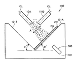
- FIG. 3 is a schematic diagram showing the implementation status (first step) of the blast treatment for the glass substrate in the present embodiment.
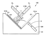
- FIG. 4 is a schematic diagram showing the implementation status (second step) of the blast treatment for the glass substrate in the present embodiment.
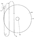
- Drawing 5 is a mimetic diagram showing the spraying situation of the particle to the glass substrate of the blast process with respect to the glass substrate in an embodiment.
- the manufacturing method of the glass substrate for hard disks which concerns on this embodiment is equipped with the roughening process which roughens the surface of the glass blanks shape
- the ratio (Ra1 / Ra2) of the upper surface roughness Ra1 and the lower surface roughness Ra2 of the glass blanks before the roughening step is 0.2 to 0.7, and the Ra1 / Ra2 is adjusted to 0.9 to 1.1.
- the surface roughness can be adjusted on the upper and lower surfaces of the glass blanks, followed by grinding. Precision control is possible in processing and polishing. Thereby, a glass substrate of very high quality (low Ra, low underi, low defect, etc.) can be obtained. Further, high quality can be achieved even in a thin plate substrate. As described above, the method for producing a glass substrate for hard disk of the present invention is extremely useful for industrial use.
- Glass blanks obtained by a normal method generally have a surface roughness ratio Ra1 / Ra2 of 0.2 to 0.7.
- the surface grinding step is a step for processing the surface of the glass blanks to have the necessary flatness and surface roughness, but before that, the surface roughness of the glass blanks is made somewhat equal on the upper and lower surfaces. By roughening the surface, it becomes possible to perform precise control in the subsequent grinding process and eventually in the polishing process.
- the Ra ratio (Ra1 / Ra2) of the upper and lower surfaces can be adjusted to 0.9 to 1.1, and precise control in the subsequent steps is possible. Specifically, Ra1 / Ra2 after the roughening process is adjusted to 0.9 to 1.1, so that the uneven grinding of the upper and lower surfaces in the grinding process of the next process is eliminated, and uniform grinding is achieved. This makes it possible to eliminate the difference in machining allowance between the upper and lower surfaces and the variation in machining allowance, and greatly improve the flatness. Further, since processing damage due to uneven polishing pressure (load) can be greatly suppressed, a processing surface that is uniform, has little damage, and has low roughness can be achieved on both the upper and lower surfaces.
- load uneven polishing pressure
- the Ra1 range before the roughening step is 0.5 ⁇ m to 1.5 ⁇ m, and the Ra2 range is about 2.0 ⁇ m to 4.0 ⁇ m, which is used in glass blank manufacturing. Although the value varies depending on the mold and the molding use elapsed time of the mold, the Ra1 / Ra2 ratio is 0.2 to 0.7.
- Ra1 and Ra2 after the roughening process can be set according to the processing conditions and time of the roughening process, and only the upper surface side with low roughness is matched to the lower surface. Rough surface formation can also be performed, and even after approximating the roughness of the lower surface, the roughening can be continued and the roughness can be added.
- Ra1 and Ra2 after roughening are preferably about 3 ⁇ m to 6 ⁇ m, but are not particularly limited.
- the surface roughness (Ra) can be measured according to Japanese Industrial Standards using, for example, a surf coder SEF3500 manufactured by Kosaka Corporation.
- the definition of the surface roughness (Ra) is based on JIS B00601: 2001 (based on ISO 4287: 1996).
- the surface grinding process which is an essential process in the present embodiment, is improved in dimensional accuracy and shape accuracy with respect to both main surfaces of the formed glass blanks, which is generally called a first grinding process. It is a process of performing a grinding process for the purpose. Details will be described later.
- the second grinding step is used for the purpose of removing damage and scratches received near the end face in the first grinding step and the previous shape processing step, and improving the accuracy of the subsequent rough polishing step and precision polishing step. You can also.
- the method for manufacturing a glass substrate for hard disk according to the present embodiment is not particularly limited with respect to the other steps as long as it includes at least the roughening step and the surface grinding step, and is used in a conventionally known manufacturing method.
- the process of obtaining can be used suitably.
- a melting process glass blanks manufacturing process
- a disk processing process a rough grinding process (first grinding process), a fine grinding process (second grinding process), and a rough polishing process
- Primary polishing step cleaning step, chemical strengthening step, mirror polishing step (secondary polishing step), and a method including a final cleaning step.
- each said process may be performed in this order, and the order of a chemical strengthening process and a mirror polishing process (secondary polishing process) may be replaced.
- a method including steps other than these may be used.
- a heat treatment step, a shape processing step, a coring step, an end surface polishing step, and an inspection step may be performed.
- a glass material for example, a general aluminosilicate glass is used.
- the aluminosilicate glass is composed of 58 mass% to 75 mass% SiO 2 , 5 mass% to 23 mass% Al 2 O 3 , 3 mass% to 10 mass% Li 2 O, and 4 mass% to 13 mass. % Na 2 O as a main component.
- the glass material is not limited to aluminosilicate glass, and may be any material such as soda lime glass or borosilicate glass.
- glass blanks which are intermediate molded bodies of glass substrates for hard disks, are produced by the direct press method. These glass blanks are generally manufactured by supplying molten glass and press-molding while cooling the molten glass.
- heat treatment may be applied to correct the flatness of the glass blank and remove internal strain.
- a coring process may be provided in order to obtain a donut-shaped substrate.
- FIG. 1 is a schematic view of a mold and a press for producing the glass blanks of the present embodiment by press molding.
- each symbol is 1 molding press machine, 2 upper part of the press machine, 3 upper mold, 4 first molding surface, 5 lower mold, 6 second molding surface, 7 lower press machine, 8 rotations.
- a press 1 for forming glass blanks includes a lower mold 5 and a lower press 7 having a first molding surface 6 to which molten glass is supplied and the supplied molten glass is pressed. It has the upper mold
- FIG. 2 is a perspective view showing a mechanism in which glass blanks are press-formed by the lower press 7 and the upper press 2 arranged on the rotary table.
- the press machine lower part 7 is embedded in the rotary table 9 side by side in the circumferential direction.
- the rotary table 9 is provided so as to be able to be driven to rotate around the rotary shaft 8 at a specific speed v (m / s).
- the molten glass 23 is supplied to the lower mold 5 by the outflow nozzle 21 at a predetermined position on the turntable.
- the lower mold 5 supplied with the molten glass 23 is transported by the rotary table together with the lower part 7 of the press machine, and the upper mold 3 installed on the upper part 2 of the press machine at another position is lowered to the position of the lower mold 5 to be melted. Pressurize the glass.
- a plurality of heaters are installed inside the mold.
- the heater is preferably arranged in one or more rounds and concentrically so as to be arranged at a uniform angle in the circumferential direction in terms of easy temperature control of the mold.
- a plurality of heaters may or may not be arranged in the press machine lower part 7 in the same manner as the press machine upper part 2, but depending on the pressurizing time to be pressed, It is preferable that they are arranged.
- the manufacture of the glass blanks in the present embodiment is mainly performed by a molten glass supply step for supplying molten glass to the first molding surface 6 formed on the lower mold 5 and a second molding surface formed on the upper mold 3. 4 and a pressurizing step of obtaining glass blanks by cooling the molten glass supplied to the first molding surface 6 while pressurizing it.
- a predetermined rough surface is formed on the molding surface 6 of the lower die 5 and the molding surface 4 of the upper die 3 for the purpose of improving the grinding rate in the next grinding step and suppressing grinding variation, and pressurizes the glass blank surface.
- the rough surface shape of the molding surface of each mold is transferred during the process.
- the molten glass In pressure molding, the molten glass first comes into contact with the molding surface of the lower mold, and after cutting with a blade, the molten glass contacts the upper molding surface and is pressed. A difference in contact time with glass occurs, and a difference occurs in the transfer ability between the molding surface of the upper mold and the molding surface of the lower mold. Therefore, the roughness of the rough surface is high on the lower surface of the glass blank that is easily transferred, and the roughness of the rough surface is low on the upper surface on which transfer is further suppressed.
- the surface roughness ratio Ra1 / Ra2 is controlled to 0.2 to 0.7. If it is less than 0.2, the difference in roughness is too great, which may hinder the blank forming speed and reduce the productivity.
- the heat treatment step is not an essential step in the present embodiment, but is a step aimed at correcting the flatness of glass blanks and removing internal distortion.
- a method of heat processing For example, the method of using a setter (alumina, zirconia, etc.) and stacking alternately with glass blanks, putting into a heat processing furnace, and applying heat can be employ
- the temperature during the heat treatment can be performed in a temperature range from Tg to Tg + 100 (° C.) of the glass blank.
- a coring process is a process of forming an inner hole (center hole) in the center part of the surface of the obtained glass blanks using a diamond core drill.
- the center of the glass blanks is determined by this coring process.
- a glass blank means the glass molding before finishing the coring process and performing the grinding process (1st grinding process) of the main plane mentioned later.
- the glass blanks that have been subjected to the coring (inner peripheral cut) process are ground with a diamond grindstone on the inner peripheral end face and the outer peripheral end face that face the hole in the center portion.
- chamfering is also performed. For example, in the case of a 2.5 inch hard disk, a predetermined chamfering process is performed after setting the outer diameter to 65 mm and the inner diameter (diameter of the circular hole 1H in the center) to 20 mm.
- the surface roughness of the end face of the glass blanks at this time is about 2 ⁇ m in Rmax.
- the roughening step is an essential step in the manufacturing method of the present embodiment.
- the Ra1 / Ra2 is set to 0.9 so that the doughnut-shaped glass blanks having different upper and lower surface roughness obtained as described above can be precisely controlled in the subsequent steps. Adjust to the range of ⁇ 1.1. This adjustment can be performed, for example, by roughening the surface by mechanical or chemical methods.
- a mechanical method for roughening for example, it can be performed by using free abrasive polishing in a flat polishing machine.
- Free abrasive polishing is a method in which a glass substrate is sandwiched between an upper surface plate and a lower surface plate while flowing high hardness alumina particles or silicon carbide particles, and the surface is shaved and roughened while applying pressure and rotating the surface plate. Is the method.
- roughening can be performed using blasting.
- the blasting process is a process of spraying a plurality of particles (abrasive grains) (for example, about 100 to 300 g) onto the main surface (upper and lower surfaces) of the glass blank formed by the above-described process. This is a process for roughening the surface.
- FIGS. 3 and 4 are schematic views showing the configuration of a blasting apparatus used for blasting for glass blanks
- FIG. 5 is a schematic view showing an implementation status of blasting for glass blanks.
- a blasting process is performed on the main surface of the glass blanks by using a blasting apparatus 100 as shown in FIGS.
- the blasting apparatus includes a support base 101 that supports the glass blanks 201 and a nozzle 110 that sprays particles (abrasive grains) onto the main surface of the glass blanks 201 supported by the support base 101.
- the blasting apparatus can perform the blasting process substantially uniformly on the entire main surfaces 202 and 203 of the glass blanks 1 by moving the support base 101 or the nozzle 110.
- the blasting apparatus 100 performs blasting of the main surface 202 of the glass blanks 201 held on the support base 101A using the nozzle 110A (first step) (FIG. 3).
- an ejection hole is formed at the tip of the nozzle 110, and particles (abrasive grains) are ejected from the ejection hole. Particles (abrasive grains) ejected from the nozzle 110 are sprayed onto the glass blank 201 while spreading in the range of the spray opening angle A ° around the center line CL.
- the nozzle 110 is arranged so that the center line CL is substantially perpendicular to the main surfaces 2 and 3.
- FIG. 5 is a schematic plan view showing the glass blanks (glass substrate precursor) 201 before the blasting process is performed by the blasting apparatus 100.
- R30 in FIG. 5 indicates a region (blast region) to be blasted (polished) by particles (abrasive grains) ejected from the nozzle 110.
- the nozzle 110 moves so as to scan the surface of the glass blank 201 in a zigzag manner (line P in the figure), for example. Thereby, the particles (abrasive grains) ejected from the nozzle 110 can be subjected to a blasting process on the entire surface of the glass blank 201.
- the nozzle 110 may be fixed and the glass blank 201 side may be moved.
- the size of the particles (abrasive grains) affects the grinding speed and the grinding amount efficiency. If the diameter of the particles (abrasive grains) is too large, the glass blanks 1 are damaged. If the diameter is too small, the glass blanks 1 cannot be ground.
- the particles (abrasive grains) those having sufficient hardness such as alumina particles, ceramic particles, SiC and the like are preferably used. It is preferable to use particles (abrasive grains) having a maximum particle size of 50 ⁇ m to 150 ⁇ m.
- the glass blanks 201 When the spray pressure of the particles (abrasive grains) is low, the glass blanks 201 may not be roughened. If the spraying pressure is too high, the glass blanks 201 may be lost.
- the machining allowance (grinding thickness) of the glass blanks 201 has a correlation with the diameter of the particles (abrasive grains). When the diameter of the particles (abrasive grains) is large, it is necessary to relatively roughen the surface. This is because cracks occur depending on the particle diameter at the initial stage of grinding.
- the spray pressure of the particles (abrasive grains) is preferably about 0.1 MPa to 1 MPa.
- the blasting process may be performed by spraying the glass blanks 201 with a plurality of particles (abrasive grains) dispersed in water. By dispersing the particles in water, there is an effect that glass waste generated by grinding can be removed at the same time. By this blasting treatment, glass blanks having a predetermined main surface roughness are obtained.
- the roughening step can be performed by a chemical method.
- a chemical method for roughening in this embodiment there is a method using an etching action by immersing glass blanks in a chemical solution.
- Examples of the chemical solution used for the chemical method include a mixture of acidic ammonium fluoride, hydrogen fluoride and the like with water. By roughening the surface by etching with acidic ammonium fluoride or hydrogen fluoride, there is an advantage that cracks do not occur.
- frost processing is also preferably used as another chemical method.
- Frost processing is processing which processes the glass surface using the chemical
- the roughening agent HF 2 - supplies are preferred. For example HF, NaF, KF 2, CaF 2 and the like. Further, the roughened state can be adjusted by adjusting the concentration and temperature of the chemical solution.
- the surface roughness ratio Ra1 / Ra2 between the upper and lower surfaces of the glass blanks is adjusted to 0.9 to 11 through the roughening step by the mechanical method or the chemical method as described above. Further, as described above, Ra1 and Ra2 after roughening are preferably about 3 to 6 ⁇ m, but are not particularly limited.
- the grinding process is performed using, for example, a double-side grinding (lapping) device using a planetary gear mechanism. Specifically, the lapping platen is pressed from above and below on both main surfaces of the glass blanks obtained above, the grinding liquid is supplied onto both main surfaces, and the glass blanks and lapping platen are relatively moved. Thus, a grinding process is performed. By the grinding process, the approximate parallelism, flatness, thickness and the like of the glass substrate are preliminarily adjusted, and a glass substrate (glass base material) having a substantially flat main surface is obtained.
- the grinding liquid for example, a grinding liquid containing alumina abrasive grains having a particle size of # 400 (particle size of about 40 to 60 ⁇ m) is used. By setting the upper surface plate load to about 100 kg, both surfaces of the glass blanks are faced. It may be finished to an accuracy of 0 ⁇ m to 1 ⁇ m and a surface roughness Rmax of about 6 ⁇ m.
- grinding may be performed using a fixed abrasive type grinding pad in which diamond particles are supported on a resin, ceramic, or metal, which has the advantage of improving the balance between grinding speed and quality after grinding.
- the particle diameter of diamond can be appropriately changed depending on the purpose, but the average particle diameter used in the first grinding is preferably 2 ⁇ m to 10 ⁇ m. If the diamond particle size is less than 2 ⁇ m for the first lapping, the processing speed is insufficient and the flatness is deteriorated, and cracks caused by the previous process on the main surface (upper and lower surfaces) of the glass substrate cannot be removed. There is a case. If the particle diameter of diamond exceeds 10 ⁇ m, there is a risk that cracks may occur on the main surfaces 2 and 3 of the glass substrate 1 due to diamond.
- the flatness of the glass substrate is measured using a white light interference surface shape measuring device Optiflat (manufactured by Phase Shift Technology).
- Optiflat manufactured by Phase Shift Technology
- a diamond pad having a particle size smaller than that of the diamond particles used in the first grinding it is preferable to use a diamond pad having a particle size smaller than that of the diamond particles used in the first grinding, so that a surface suitable for polishing in the next step is used. Properties can be formed.
- diamond particles having an average particle diameter of 1 ⁇ m to 5 ⁇ m are used. With the recent increase in density, the diamond particle diameter is becoming smaller, but a balance of workability is required, so 1.5 ⁇ m to 4 ⁇ m is more preferable.
- the glass substrate main surface (upper and lower surfaces) is ground to a thickness of about 50 ⁇ m to 2300 ⁇ m.
- mirror polishing by brush polishing may be performed on the inner peripheral end surface of the glass substrate. Specifically, by supplying a polishing liquid containing an abrasive to the polishing brush, placing the polishing brush in contact with the inner peripheral end surface of the glass substrate, and applying the polishing brush while rotating the glass substrate The inner peripheral end face of the glass substrate is polished.
- abrasive cerium oxide is usually selected and supplied as a polishing liquid at an appropriate concentration.
- the polishing brush a brush having an appropriate hardness and diameter is selected so that the polishing can be performed softly without damaging the end face.
- an outer peripheral polishing step may be further performed.
- mirror polishing by brush polishing is performed on the outer peripheral end surface of the glass substrate.
- a polishing liquid containing an abrasive to the polishing brush, placing the polishing brush in contact with the outer peripheral end surface of the glass substrate, and applying the polishing brush while rotating the glass substrate, The outer peripheral end surface of the glass substrate is polished.
- the abrasive and the polishing brush are selected in the same manner as the abrasive and the polishing brush used for polishing the inner peripheral end face of the glass substrate.
- the rough polishing step is a step of polishing both main surfaces of the glass substrate with an abrasive slurry so that the surface roughness finally required in the subsequent mirror polishing step can be efficiently obtained. It does not specifically limit as a grinding
- the polishing pad to be used when the hardness of the polishing pad decreases due to heat generated by polishing, the shape change of the polishing surface becomes large. Therefore, it is preferable to use a hard pad, for example, urethane foam.
- a hard pad for example, urethane foam.
- cerium oxide having an average primary particle size of 0.6 to 2.5 ⁇ m is used, and cerium oxide is dispersed in a solvent to form a slurry. It does not specifically limit as a solvent, Neutral water and acidic / alkaline aqueous solution are employable. Moreover, a dispersing agent can be added to these solvents. The mixing ratio of the solvent and cerium oxide is about 1: 9 to 3: 7.
- the polishing pad tends to fail to polish both main surfaces well.
- the polishing pad may deteriorate the flatness of the end face or generate scratches.
- the supply amount of the abrasive slurry is not particularly limited and is, for example, 5 to 10 L / min.
- the polishing amount of the glass substrate in the rough polishing step is preferably about 20 to 40 ⁇ m.
- the polishing amount of the glass substrate is less than 20 ⁇ m, there is a tendency that scratches and defects are not sufficiently removed.
- the polishing amount of the glass substrate exceeds 40 ⁇ m, the glass substrate is polished more than necessary, and the production efficiency tends to decrease.
- the glass substrate after the rough polishing step is preferably washed with a neutral detergent, pure water, IPA or the like.
- a cleaning step may be provided, and the surface of the glass substrate is cleaned with a cleaning solution containing sulfuric acid and / or hydrofluoric acid for the purpose of removing any of the cerium oxide, zirconium oxide, or zirconium silicate in the previous step. Clean while etching.
- a polishing slurry such as cerium oxide, zirconium oxide, or zirconium silicate adhering to the surface of the glass substrate is appropriately removed by a strongly acidic cleaning liquid such as sulfuric acid and / or hydrofluoric acid. Thereafter, the glass substrate is cleaned using an acidic cleaning solution.
- the cleaning liquid used in the cleaning step varies depending on the chemical resistance of the glass substrate, but a concentration of about 1% to 30% is preferable for sulfuric acid, and about 0.2% to 5% for hydrofluoric acid. Concentration is preferred. Cleaning using these cleaning liquids may be performed while applying ultrasonic waves in a cleaning machine in which an aqueous solution is stored.
- the frequency of the ultrasonic wave used at this time is preferably 78 kHz or higher.
- the chemical strengthening step is a step of immersing the glass substrate in a strengthening treatment liquid to improve the impact resistance, vibration resistance, heat resistance, and the like of the glass substrate.
- the chemical strengthening step is a step of chemically strengthening the glass substrate.
- the strengthening treatment liquid used for chemical strengthening include a mixed solution of potassium nitrate (60%) and sodium nitrate (40%).
- Chemical strengthening can be performed by heating the strengthening treatment liquid to 300 to 400 ° C., preheating the glass substrate to 200 to 300 ° C., and immersing in the strengthening treatment liquid for 3 to 4 hours. In this immersion, it is preferable that the immersion is performed in a state of being housed in a holder that holds the end faces of the plurality of glass substrates so that both main surfaces of the glass substrate are chemically strengthened.
- a standby process for waiting the glass substrate in the air and a water immersion process are adopted to remove the strengthening treatment liquid adhering to the surface of the glass substrate and to homogenize the surface of the glass substrate. It is preferable.
- the chemically strengthened layer is formed uniformly, the compressive strain is uniform, deformation is difficult to occur, the flatness is good, and the mechanical strength is also good.
- the waiting time and the water temperature in the water immersing step are not particularly limited. For example, it may be kept in the air for 1 to 60 seconds and immersed in water at about 35 to 100 ° C., and may be determined appropriately in consideration of production efficiency.
- the mirror polishing process is a process of polishing both main surfaces of the glass substrate more precisely.
- a double-side polishing machine similar to the double-side polishing machine used in the rough polishing process can be used.
- the polishing pad is preferably a soft pad having a lower hardness than the polishing pad used in the rough polishing step.
- urethane foam or suede is preferably used.
- a slurry containing cerium oxide or the like similar to the coarse polishing step can be used.
- an abrasive slurry having a finer grain size and less variation it is preferable to use a slurry obtained by dispersing colloidal silica having an average particle diameter of 40 to 70 nm in a solvent to form a slurry. It does not specifically limit as a solvent, Neutral water and acidic / alkaline aqueous solution are employable.
- a dispersing agent can be added to these solvents.
- the mixing ratio of the solvent and colloidal silica is preferably about 1: 9 to 3: 7.
- the supply amount of the abrasive slurry is not particularly limited, and is, for example, 0.5 to 1 L / min.
- the polishing amount in the mirror polishing step is preferably about 2 to 5 ⁇ m.
- the obtained glass substrate can remove fine defects such as minute roughness and waviness generated on the surface of the glass substrate, or minute scratches generated in the previous process. Is done.
- the glass substrate manufacturing method of the present invention can improve the flatness of the obtained glass substrate, and can produce a glass substrate on which the magnetic head can float more stably in the end region.
- the flatness of both main surfaces of the glass substrate is reduced to 3 ⁇ m or less, and the surface roughness Ra of both main surfaces of the glass substrate is reduced to 0.1 nm. be able to.
- the final cleaning step is a step of cleaning and cleaning the glass substrate. It does not specifically limit as a washing
- a cleaning liquid such as a detergent or pure water is used.
- the pH of the cleaning solution used for scrub cleaning is preferably 9.0 or more and 12.2 or less. Within this range, the ⁇ potential can be easily adjusted and scrub cleaning can be performed efficiently.
- both scrub cleaning with a detergent and scrub cleaning with pure water may be performed.
- the glass substrate 1 can be more appropriately cleaned.
- the glass substrate 1 may be further rinsed with pure water between scrub cleaning with a detergent and scrub cleaning with pure water.
- the glass substrate may be further subjected to ultrasonic cleaning.
- ultrasonic cleaning with chemical solution such as sulfuric acid aqueous solution, ultrasonic cleaning with pure water, ultrasonic cleaning with detergent, ultrasonic cleaning with IPA, and / or steam drying with IPA, etc. Further, it may be performed.
- the cleaned glass substrate is subjected to ultrasonic cleaning and drying steps as necessary.
- the drying step is a step of drying the surface of the glass substrate after removing the cleaning liquid remaining on the surface of the glass substrate with isopropyl alcohol (IPA) or the like.
- IPA isopropyl alcohol
- a water rinse cleaning process is performed on the glass substrate after scrub cleaning for 2 minutes to remove the cleaning liquid residue.
- an IPA cleaning process is performed for 2 minutes, and water remaining on the surface of the glass substrate is removed by IPA.
- the IPA vapor drying step is performed for 2 minutes, and the liquid IPA adhering to the surface of the glass substrate is dried while being removed by the IPA vapor.
- the drying process of the glass substrate is not particularly limited, and for example, a known drying method such as spin drying or air knife drying can be employed.
- the glass substrate that has undergone the final cleaning step may be further subjected to an inspection step before shipment.
- the inspection step is a step of inspecting the glass substrate that has undergone the above-described steps for the presence or absence of scratches, cracks, foreign matters, and the like.
- the inspection is performed visually or using an optical surface analyzer (for example, “OSA6100” manufactured by KLA-TENCOL).
- OSA6100 manufactured by KLA-TENCOL
- the method for producing a glass substrate for hard disk includes a roughening step for roughening a surface of glass blanks formed by a press method after melting glass, and a surface grinding step performed thereafter. And the ratio (Ra1 / Ra2) of the upper surface roughness Ra1 and the lower surface roughness Ra2 of the glass blank before the roughening step is 0.2 to 0.7, and the surface roughening step Ra1 / Ra2 is adjusted to 0.9 to 1.1.
- Such a configuration makes it possible to adjust the surface roughness on the upper and lower surfaces of the glass blanks and to perform precise control in the subsequent grinding and polishing processes. Thereby, a glass substrate of very high quality (low Ra, low underi, low defect, etc.) can be obtained. Further, high quality can be achieved even in a thin plate substrate.
- the roughening step is performed by a mechanical method or a chemical method. Thereby, it is thought that the rough surface property which this invention aims at can be arranged more reliably in the upper and lower surfaces of glass blanks.
- the glass blanks that have undergone the roughening step are ground using a pad having diamond particles as fixed abrasive grains in the surface grinding step.
- the grinding speed is high and the grinding process can be performed more precisely.
- the free abrasive method a problem of cleanability due to abrasive contamination is likely to occur.
- an average particle diameter of the diamond particles is 4 ⁇ m or less. Therefore, the grinding process can be performed more precisely.
- blasting is performed as the mechanical method in the roughening step.
- the rough surface property desired in the present invention can be accurately adjusted on the upper and lower surfaces of the glass blank.
- the roughening step it is also preferable to use an etching action with a chemical as the chemical method. Thereby, it is considered that the surface roughness can be adjusted more reliably on the upper and lower surfaces of the glass blanks.
- the chemical solution preferably has a pH in the range of 7.0 to 3.0.
- the glass blanks preferably have a thickness of 1 mm or less. This is because the manufacturing method of the present invention can exert an effect even on such a thin plate substrate.
- Glass melting process As the glass material, SiO 2 of 61 wt%, 3 wt% of Al 2 O 3, 2.7 wt% of Na 2 O, 6.9 wt% K 2 O, 5.7 wt% of MgO, 11. In order to obtain an aluminosilicate glass containing 5% by mass of CaO and 9% by mass of ZrO 2 , each raw material was prepared and melted at 1500 ° C. using a platinum crucible.
- a glass gob supplied to the center of the lower mold forming surface was used with an upper mold facing the lower mold, and a tungsten-based material was used for the upper mold and the lower mold.
- the pressing time was 1 second, and butt molding was performed so that the thickness of the blanks after molding was uniform.
- the plate thickness after molding was 1.1 mm on average.
- the glass blanks were roughened by spraying particles (abrasive grains) using the blasting apparatus shown in FIGS.
- Alumina particles were used as particles (abrasive grains), the alumina particles were 110 ⁇ m, and the opening diameter of the nozzle 110 was 6.5 mm.
- the spraying pressure and the spraying time were changed to change to Ra1 / Ra2 described in Table 1 (Examples 1 to 3 and Comparative Examples 4 to 5). ).
- the glass substrates of Comparative Examples 1 to 3 were subjected to a post process without performing a roughening process.
- the main surface (upper and lower surfaces) of the glass substrate was processed by using diamond grains made of acrylic resin as abrasive grains.
- the diamond particle diameter was 4 ⁇ m.
- the flatness after the first grinding was measured using FT-11 (flatness measuring machine) manufactured by NiDEK and listed in Table 1.
- the main surface (upper and lower surfaces) of the glass substrate was processed using a diamond-shaped diamond resin sheet.
- a diamond particle diameter of 1.5 ⁇ m was used.
- the glass substrate 1 main surface (upper and lower surfaces) was ground to about 250 ⁇ m.
- the main surface of the glass substrate was polished with a polishing slurry (made by Hamai Co., Ltd.) using a polishing slurry containing 10% cerium oxide and a suede-shaped polishing pad made of foamed polyurethane.
- the polishing conditions, and a load 120 g / cm 2, and the rotation rate of the upper stool 15 rpm, the rotational speed 50rpm of the lower stool were performed while changing as appropriate during these processes.
- the substrate was washed to remove the attached abrasive.
- chemical strengthening process chemical strengthening was performed on the glass substrate after the above steps. Specifically, first, a mixed melt obtained by melting a solid of potassium nitrate and sodium nitrate was prepared. In addition, this mixed melt is mixed so that the mixing ratio of potassium nitrate and sodium nitrate is 8: 2 by mass ratio. Then, this mixed melt was heated to 400 ° C., and the washed glass base plate was immersed in the heated mixed melt for 60 minutes.
- the glass substrate was scrubbed.
- a cleaning liquid a liquid obtained by diluting KOH and NaOH mixed at a mass ratio of 1: 1 with ultrapure water (DI water) and adding a nonionic surfactant to enhance the cleaning performance is obtained.
- DI water ultrapure water
- the cleaning liquid was supplied by spraying. After scrub cleaning, in order to remove the cleaning liquid remaining on the surface of the glass substrate, a water rinse cleaning process is performed in an ultrasonic bath for 2 minutes, an IPA cleaning process is performed in an ultrasonic bath for 2 minutes, and finally the glass substrate is cleaned with IPA vapor. The surface of was dried.
- the surface roughness Ra of the glass substrate was an average value obtained by measuring 5 sheets each ⁇ 3 points in the plane within a range of 1 ⁇ m square using AFM of Veeco.
- the minute seaweed ⁇ Wa was measured using a non-contact surface shape measuring device (New View 5000) of “Zygo Corporation”.
- the minute undulation ⁇ Wa is measured by optical interference (Newton ring), and the amount of deviation between the reference plane and the actual plane is measured as interference fringes.
- the measurement principle is a method of measuring a subtle shape change of the surface by irradiating the surface of the substrate with white light and measuring an intensity change of interference between the reference light and the measurement light having different phases.
- An average value of the surface waviness height obtained by extracting irregularities with a period of 30 to 200 ⁇ m from the obtained measurement data is defined as minute undulation ⁇ Wa.
- a total of 100 glass substrates processed in each example and each comparative example are inspected, and a substrate determined to have a deposit of 10 or less and a scratch of 2 or less is determined to be a non-defective product.
- Test Example 2 Same as Examples 1 to 3 and Comparative Examples 1 to 5 of Test Example 1 except that the thickness after the glass blank forming step is 0.90 mm and the final thickness of the substrate is 0.65 mm. Each process was performed on the conditions of this, and the thin glass substrate was created.
- the glass substrate obtained by the production method of the present invention was far superior to the comparative example in any evaluation.
- Test Example 3 A substrate was prepared in the same manner as in Test Example 1 except that the glass blank roughening step was performed by a chemical etching method.
- the glass substrate was immersed in a treatment solution containing ammonium acid fluoride.
- a treatment solution containing ammonium acid fluoride By changing the conditions such as the immersion time, treatment solution temperature, ammonium fluoride concentration, etc., the conditions were changed to Ra1 / Ra2 shown in Table 2 (Examples 7 to 9 and Comparative Examples 11 to 12).
- the glass substrate obtained by the production method of the present invention was far superior to the comparative example in any evaluation. Since the chemical etching method has the effect of reducing processing damage and scratches occurring in the glass blank molding, the defect count is smaller than the glass substrate that has been subjected to the roughening process by the blast method of Test Example 1, It was shown that it was superior in the non-defective product judgment.
- the present invention has wide industrial applicability in the technical field of glass substrates for hard disks and their manufacturing methods.
Landscapes
- Chemical & Material Sciences (AREA)
- Engineering & Computer Science (AREA)
- Geochemistry & Mineralogy (AREA)
- Life Sciences & Earth Sciences (AREA)
- Chemical Kinetics & Catalysis (AREA)
- General Chemical & Material Sciences (AREA)
- Materials Engineering (AREA)
- Organic Chemistry (AREA)
- Mechanical Engineering (AREA)
- Manufacturing & Machinery (AREA)
- Manufacturing Of Magnetic Record Carriers (AREA)
- Grinding Of Cylindrical And Plane Surfaces (AREA)
- Surface Treatment Of Glass (AREA)
Abstract
本発明は、ハードディスク用ガラス基板の製造方法であって、ガラスを溶融した後にプレス法で成形したガラスブランクスの表面を粗面化する粗面化工程、及び、その後に行われる表面研削工程を備えること、並びに前記粗面化工程前のガラスブランクスの上面粗さRa1と下面表面粗さRa2の比(Ra1/Ra2)が0.2~0.7であり、前記粗面化工程によって前記Ra1/Ra2を0.9~1.1に調整することを特徴とする、ハードディスク用ガラス基板の製造方法に関する。
Description
本発明は、ハードディスク(HDD)に搭載する磁気ディスクとして用いられるハードディスク(磁気情報記録媒体)用ガラス基板の製造方法に関する。
HDD等の磁気情報記録媒体用のガラス基板は、通常、フロート法やダイレクトプレス法により得られた平板状のガラス素板に対し、研削工程、研磨工程、化学強化工程などを行うことによって作製される。
ダイレクトプレス法は高いガラス転移点をもち、高い強度を有するガラス組成群に適する製法であり、フロート法では得られにくい高いヤング率・強度のガラス基板を得ることができる。しかしながら、ダイレクトプレス法においては、溶融されたガラスを金型で加圧することによりガラスブランクスといわれるガラス製の中間成形体を作るが、このガラスブランクスでは生産性向上を狙いとして付着などの問題が生じないように、成型時の金型形状及び成形条件が調整される。ところが、それ故にガラスブランクスの上下面において粗面性に差が生じてしまうことがある。
一方、HDDの高密度化の要求によりガラス基板も高清澄化、平坦化が望まれており、ガラスブランクスの表面粗さ(Ra)、ウネリなどの品質の向上が、これまで以上に必要とされている。この品質要求に応えるには、高精度な加工技術が必須であり、精密なコントロールに基づく研削、研磨法が必要になると考えられる。
これまでに、ガラス基板の製造方法における研削の加工レートを上げるために、研削工程前にガラス基板表面を粗面化する方法が知られている(例えば、特許文献1および2参照)。
しかしながら、これまでに知られている、研削工程前に粗面化する手法はいずれもフロート法によって得られる、表面が鏡面化したガラス素板に対して行われるものであり、その目的も粗面化することで研削時の砥粒剤とガラス素板との摩擦力を上げ、滑りを抑えることで加工レートの向上を主とするものであった。
フロート法と異なり、ダイレクトプレス法で作られたガラスブランクスは、上述したようにその上下面において粗面差があるために、高密度化の品質に応える加工を施すと、上面、下面での粗面差が上下の加工性のばらつきを拡大させ、高品質を狙い精密に仕上げようとする程、品質を下げてしまうという問題があった。
また、HDDドライブの負荷軽減や磁性メディアのフラッタリング軽減に優位に作用する基板の薄板化によって、薄板であるために平坦度を整えるためのひずみや欠陥除去するための取り代の制限が大きくなったり、ダイレクトプレス法によるガラスブランクスの上下面の粗面性の差によって片面平坦度の不足、平坦度バラツキ、強いては品質低下の問題も生じていた。
本発明はかかる事情に鑑みてなされたものであって、ダイレクトプレス法で得られるガラスブランクスを用いた場合でも高精度に加工でき、高密度化の要求に応えうる品質を確保することができる、ハードディスク用ガラス基板を製造する方法を提供することを目的とする。
本発明者は、鋭意検討した結果、下記構成を有する製造方法によって、前記課題が解決することを見出し、かかる知見に基づいて更に検討を重ねることによって本発明を完成した。
すなわち、本発明の一局面に係るハードディスク用ガラス基板の製造方法は、ガラスを溶融した後にプレス法で成形したガラスブランクスの表面を粗面化する粗面化工程、及び、その後に行われる表面研削工程を備えること、並びに、前記粗面化工程前のガラスブランクスの上面粗さRa1と下面表面粗さRa2の比(Ra1/Ra2)が0.2~0.7であり、前記粗面化工程によって前記Ra1/Ra2を0.9~1.1に調整することを特徴とする。
本実施形態に係るハードディスク用ガラス基板の製造方法は、ガラスを溶融した後にプレス法で成形したガラスブランクスの表面を粗面化する粗面化工程、及び、その後に行われる表面研削工程を備えること、並びに、前記粗面化工程前のガラスブランクスの上面粗さRa1と下面表面粗さRa2の比(Ra1/Ra2)が0.2~0.7であり、前記粗面化工程によって前記Ra1/Ra2を0.9~1.1に調整することを特徴とする。
このような構成によれば、ハードディスク用ガラス基板の製造方法において、ダイレクトプレス法によって得られるガラスブランクスを用いた場合でも、ガラスブランクスの上下面において粗面性を整えることができ、その後に続く研削加工および研磨加工において精密制御が可能となる。それにより、非常に高い品質(低Ra、低ウネリ、低ディフェクトなど)のガラス基板を得ることができる。また、薄板基板においても高品質を達成することができる。以上のように、本発明のハードディスク用ガラス基板の製造方法は産業利用上きわめて有用である。
以下、本発明に係る実施形態についてより具体的に説明するが、本発明はこれらに限定されるものではない。
通常の方法(例えば、後述するブランクス製造工程)により得られるガラスブランクスは、概ね上下面の表面粗さの比:Ra1/Ra2が0.2~0.7となっている。
前記表面研削工程とは、ガラスブランクスの表面を必要な平坦度および表面粗さにするために加工する工程であるが、その前にガラスブランクスの表面粗さが、上下面である程度同等となるように粗面化を施すことにより、その後の研削工程、ひいては研磨工程において精密なコントロールを行うことが可能となる。
なお、粗面化工程前のガラスブランクスの上下面の表面粗さの比:Ra1/Ra2が0.2未満であると、上下面におけるRaの差が乖離しすぎているので、ある程度のRaやウネリなどの低下は達成することができるが、十分な効果が発揮されないおそれもある。一方、ガラスブランクスの上面粗さRa1と下面表面粗さRa2の比(Ra1/Ra2)が0.2~0.7であれば、上述したような本発明の効果は存分に発揮される。
本実施形態の粗面化工程を経ることにより、上下面のRa比(Ra1/Ra2)が0.9~1.1に調整でき、その後の工程における精密なコントロールを可能にする。具体的には、粗面化工程後のRa1/Ra2が0.9~1.1に調整されたことにより、次工程の研削加工での上下面の研削の偏りが解消し、均一な研削が可能となり上下面の取り代差、取り代のばらつきが解消され、平坦度が大幅に向上する。また、研磨圧(負荷)の偏りによる加工ダメージを大きく抑制できるため、均質でダメージが少なく粗さも抑えた加工面が上下面の両方において達成される。更に研削加工で良好な面質が上下面で提供されたことにより、次工程の研磨(仕上げ)工程での加工負荷が大幅に減少し精密でソフトな加工が可能となるめ、非常に高品質(低Ra、低ウネリ、低ディフェクト)のガラス基板を実現できる。
粗面化工程前(後述の形状加工工程後に測定したもの)のRa1の範囲は0.5μm~1.5μm、Ra2の範囲は2.0μm~4.0μm程度であり、ガラスブランクス製造において使われる型や型の成形使用経過時間により値は変わるが、Ra1/Ra2比は0.2~0.7になる。
粗面化工程の詳細については後述するが、粗面化工程後のRa1、Ra2の範囲は粗面化工程の加工条件・時間により設定でき、粗さの低い上面側だけを下面に合わせるように粗面形成を行うこともできるし、下面の粗さに近似したあとも粗面化を継続し粗さを上乗せすることもできる。粗面化後のRa1、Ra2は3μm~6μm程度であることが好ましいが、特に限定はされない。
なお、前記表面粗さ(Ra)測定は、例えば、株式会社小坂製のサーフコーダーSEF3500を用いて日本工業規格にのっとり行うことができる。また、本実施形態において、表面粗さ(Ra)の定義については、JIS B00601:2001(ISO 4287:1996に準拠)に基づいている。
また、本実施形態において必須の工程である、前記表面研削工程は、一般に第1研削工程と呼ばれている、成形されたガラスブランクスの両方の主表面に対して、寸法精度および形状精度の向上を目的として研削処理を行う工程である。詳細については後述する。本発明においては、第1研削工程やその前の形状加工工程で端面付近において受けたダメージ・傷を取り払い、後続の粗研磨工程、精密研磨工程の精度を高める目的において第2研削工程を用いることもできる。
本実施形態に係るハードディスク用ガラス基板の製造方法は、前記粗面化工程と前記表面研削工程とを少なくとも備えている限り、その他の工程については特に限定されず、従来公知の製造方法で用いられ得る工程を適宜使用することができる。
ハードディスク用ガラス基板の製造方法としては、通常、例えば、溶融工程(ガラスブランクス製造工程)、円盤加工工程、粗研削工程(第1研削工程)、精研削工程(第2研削工程)、粗研磨工程(1次研磨工程)、洗浄工程、化学強化工程、鏡面研磨工程(2次研磨工程)、及び最終洗浄工程等を備える方法等が挙げられる。そして、前記各工程を、この順番で行うものであってもよいし、化学強化工程と鏡面研磨工程(2次研磨工程)との順番が入れ替わったものであってもよい。さらに、これら以外の工程を備える方法であってもよい。例えば、上記以外に、熱処理工程、形状加工工程、コアリング工程、端面研磨工程や検査工程を行ってもよい。
以下に、本実施形態に係るハードディスク用ガラス基板の製造方法の一実施態様について説明する。
<ガラスブランクス製造工程>
まず、ガラス素材としては、たとえば一般的なアルミノシリケートガラスが用いられる。アルミノシリケートガラスは、58質量%~75質量%のSiO2と、5質量%~23質量%のAl2O3と、3質量%~10質量%のLi2Oと、4質量%~13質量%のNa2Oと、を主成分として含有する。ガラス素材は、アルミノシリケートガラスに限られるものではなく、ソーダライムガラス、ホウケイ酸ガラスなど、任意の素材であってもよい。
まず、ガラス素材としては、たとえば一般的なアルミノシリケートガラスが用いられる。アルミノシリケートガラスは、58質量%~75質量%のSiO2と、5質量%~23質量%のAl2O3と、3質量%~10質量%のLi2Oと、4質量%~13質量%のNa2Oと、を主成分として含有する。ガラス素材は、アルミノシリケートガラスに限られるものではなく、ソーダライムガラス、ホウケイ酸ガラスなど、任意の素材であってもよい。
次に、ダイレクトプレス法により、ハードディスク用ガラス基板の中間成形体であるガラスブランクスを製造する。このガラスブランクスは、溶融ガラスを供給し、その溶融ガラスを冷却しながら加圧成形して製造されるのが一般的である。本実施形態のガラスブランクスの製造においては、上記の工程の他に、前記ガラスブランクスの平坦度を修正し、内部歪みを除去するために熱処理が施してもよい。また、ドーナツ状基板にするためにコアリング工程が設けてもよい。
図1は、本実施形態のガラスブランクスをプレス成形で作成するための金型及びプレス機の模式図である。
なお、以下の図面において各符号は、1 成型用プレス機、2 プレス機上部、3 上型、4 第1の成形面、5 下型、6 第2の成形面、7 プレス機下部、8 回転軸、9 回転テーブル、21 流出ノズル、23 溶融ガラス、201 ガラスブランクス、202、3 主表面、100 ブラスト装置、101A,101B 支持台、110A,110B ノズル、300 エアーノズルを示す。
図1において、ガラスブランクス成形用のプレス機1は、溶融ガラスが供給され、供給された該溶融ガラスを加圧するための第1の成形面6を備える下型5及びプレス機下部7と、下型5の第1の成形面6との間で溶融ガラスを加圧するための第2の成形面4を備える上型3及びプレス機上部2とを有している。
図2は、回転テーブルに並べられたプレス機下部7とプレス機上部2によってガラスブランクスをプレス成形される機構を表した斜視図である。プレス機下部7は、回転テーブル9に円周方向に並べて埋設されている。該回転テーブル9は、回転軸8の周りを特定の速度v(m/s)にて回転駆動可能となるように設けられている。
またプレス機下部7の上に金型の下型5が設置されているが、回転台上の所定の位置において溶融ガラス23が流出ノズル21によって下型5へ供給される。溶融ガラス23が供給された下型5は、プレス機下部7とともに回転テーブルによって移送され、別の位置においてプレス機上部2に設置された上型3を、下型5の位置まで下降させて溶融ガラスを加圧する。
金型の内部には、複数のヒーターが埋め込まれるように設置されている。該ヒーターは、周方向に均一角度で配置されるように、一周又は複数周状であって同心円状に埋め込まれていることが、金型の温度制御をしやすいという点で好ましい。なお、プレス機下部7には、前記プレス機上部2と同様に複数のヒーターを配置されていてもよいし配置されていなくてもよいが、プレスされる加圧時間によってはプレス機下部7に配置されていた方が好ましい。
よって、本実施形態におけるガラスブランクスの製造は、主として下型5に形成された第1の成形面6に溶融ガラスを供給する溶融ガラス供給工程と、上型3に形成された第2の成形面4で、第1の成形面6に供給された溶融ガラスを加圧しながら冷却してガラスブランクスを得る加圧工程とを備えるものである。
下型5の成形面6、上型3の成形面4には次工程の研削工程の研削レート向上及び研削バラツキの抑制の目的で所定の粗面を形成しており、ガラスブランクス表面に加圧工程時に各型の成形面の粗面形状が転写されるようにしている。
このガラスブランクスの上下面の粗面形状に関して既に述べたように上下面の表面粗さに差が生じてしまう。それは以下の理由によると考えられる。
加圧成形はまず下型の成形面に溶融ガラスが接触し、ブレードで切断した後に上型の成形面と接触し加圧されるという順次工程を経るために、どうしても下型と上型の溶融ガラスへの接触時間の差が生じてしまい、上型の成形面と下型の成形面の転写能に差が生じることとなる。従って、転写されやすいガラスブランクスの下面は粗面の粗さが高く、転写がより抑制されてしまう上面は粗面の粗さが低くなる。本実施形態ではその表面粗さの比Ra1/Ra2は0.2~0.7に制御されている。0.2未満だと粗さの差があまりにも大きく、ブランクス成形速度に支障を来し、生産性を落としてしまう懸念がある。また0.7より大きくすることは本発明の効果の発揮という面においては有効であるが、0.7以上にするために上型の転写性をよくする手段をとる必要がでてくるため、プレス時間を長くしたり、粗面を粗くする手段が上げられるが、生産性下落やプレス型へのブランクスの付着を招き、大きな問題となるおそれがある。
<熱処理工程>
熱処理工程は、本実施形態において必須の工程ではないが、ガラスブランクスの平坦度の修正および内部歪みの除去を目的とする工程である。熱処理の方法としては特に限定されないが、たとえばセッター(アルミナ、ジルコニア等)を用いて、ガラスブランクスと交互に積み重ねて熱処理炉に入れて熱を加える方法を採用することができる。
熱処理工程は、本実施形態において必須の工程ではないが、ガラスブランクスの平坦度の修正および内部歪みの除去を目的とする工程である。熱処理の方法としては特に限定されないが、たとえばセッター(アルミナ、ジルコニア等)を用いて、ガラスブランクスと交互に積み重ねて熱処理炉に入れて熱を加える方法を採用することができる。
熱処理の条件としては特に制限されない。たとえば、熱処理時の温度としては、ガラスブランクスのTgからTg+100(℃)の温度範囲で行うことができる。当該温度範囲内で熱処理を行うことにより、ガラスブランクスの平坦度を充分に修正することができるとともに、ガラスブランクスの形状の悪化を低減し、さらにセッターとの間の融着に起因する粘着痕の発生する可能性を低減することができる。
<コアリング工程>
コアリング工程は、得られたガラスブランクスの表面の中心部にダイヤモンドコアドリルを用いて内孔(中心孔)を形成する工程である。このコアリング工程によって、ガラスブランクスの中心が決定される。なお、本実施形態において、ガラスブランクスとは、コアリング工程を終え、後述する主平面の研削工程(第1研削工程)が行われる前のガラス成形物をいう。
コアリング工程は、得られたガラスブランクスの表面の中心部にダイヤモンドコアドリルを用いて内孔(中心孔)を形成する工程である。このコアリング工程によって、ガラスブランクスの中心が決定される。なお、本実施形態において、ガラスブランクスとは、コアリング工程を終え、後述する主平面の研削工程(第1研削工程)が行われる前のガラス成形物をいう。
<形状加工工程>
次に、形状加工工程においては、コアリング(内周カット)処理が施されたガラスブランクスを、中心部の孔に対向する内周端面、および、外周端面を、ダイヤモンド砥石によって研削し、所定の寸法に調整された後、面取り加工も実施される。例えば2.5インチ型ハードィスクの場合は外径を65mm、内径(中心部の円孔1Hの直径)を20mmとした後、所定の面取り加工が実施される。このときのガラスブランクスの端面の面粗さは、Rmaxで2μm程度である。
次に、形状加工工程においては、コアリング(内周カット)処理が施されたガラスブランクスを、中心部の孔に対向する内周端面、および、外周端面を、ダイヤモンド砥石によって研削し、所定の寸法に調整された後、面取り加工も実施される。例えば2.5インチ型ハードィスクの場合は外径を65mm、内径(中心部の円孔1Hの直径)を20mmとした後、所定の面取り加工が実施される。このときのガラスブランクスの端面の面粗さは、Rmaxで2μm程度である。
<粗面化工程>
粗面化工程は、本実施形態の製造方法において必須の工程である。
粗面化工程は、本実施形態の製造方法において必須の工程である。
本工程では、上述にようにして得られた、上下の面の粗さが異なるドーナツ状のガラスブランクスを、後続の工程において精密制御加工が可能となるように、前記Ra1/Ra2を0.9~1.1の範囲に調整する。この調整は、例えば、機械的方法又は化学的方法によって表面を粗面化することによって行うことができる。
(機械的方法)
粗面化する機械的方法としては、例えば、平面研磨機において遊離砥粒研磨を用いて行うことができる。遊離砥粒研磨とは硬度の高いアルミナ粒子もしくは炭化ケイ素粒子などを流動させながら上定盤と下定盤間にガラス基板を、挟み圧をかけ、定盤を回転させながら表面を削り粗面化する方法である。
粗面化する機械的方法としては、例えば、平面研磨機において遊離砥粒研磨を用いて行うことができる。遊離砥粒研磨とは硬度の高いアルミナ粒子もしくは炭化ケイ素粒子などを流動させながら上定盤と下定盤間にガラス基板を、挟み圧をかけ、定盤を回転させながら表面を削り粗面化する方法である。
あるいは、その他の機械的方法として、好ましくは、ブラスト処理を用いて粗面化を行うことができる。
本実施形態においてブラスト処理とは、上述した工程によって形成されたガラスブランクスの主表面(上下面)に複数の粒子(砥粒)(例えば、100~300g程度)を吹き付けることによって、ガラスブランクスの主表面の粗面化を行なう処理である。
図3~図5を参照して、ブラスト処理について説明する。図3および4は、ガラスブランクスに対するブラスト処理に用いられるブラスト装置の構成を示す模式図、図5は、ガラスブランクスに対するブラスト処理の実施状況を示す模式図である。
図3~図4に参照されるようなブラスト装置100を用いて、ガラスブランクスの主表面にブラスト処理を施す。ブラスト装置は、ガラスブランクス201を支持する支持台101と、支持台101によって支持されたガラスブランクス201の主表面に粒子(砥粒)を吹きつけるノズル110とを含む。ブラスト装置は、支持台101を動かすこと、または、ノズル110を動かすことで、ガラスブランクス1の主表面202,203の全面に略均等にブラスト処理を施すことができる。
まず、ブラスト装置100は、ノズル110Aを用いて、支持台101Aに保持されたガラスブランクス201の主表面202のブラスト処理を行う(第1工程)(図3)。
次に、主表面202のブラスト処理が終了すると、エアーノズル300からエアーをガラスブランクス201に対して吹き付けて、支持台101A側に載置されたガラスブランクス1を、反対側の支持台101B側に反転させる。その後、ガラスブランクス201の他方の主表面203に対して、ノズル110Bを用いて、粒子を吹き付ける工程(第2工程)を実施する。この第2工程におけるガラスブランクス1の主表面203に対する粒子(砥粒)の吹き付け条件は、第1工程と同じである。
前記第1工程においても第2工程においても、ノズル110の先端部には、噴出孔が形成されており、この噴出孔から粒子(砥粒)が噴出される。ノズル110から噴出された粒子(砥粒)は、中心線CLを中心として、吹き付け開口角A°の範囲で広がりながらガラスブランクス201に吹き付けられる。ガラスブランクス201にブラスト処理を施す際には、ノズル110は、中心線CLが主表面2,3に対して略垂直となるように配置される。
図5は、ブラスト装置100によってブラスト処理が施される前のガラスブランクス(ガラス基板前駆体)201を示す模式的な平面図である。図5中のR30は、ノズル110から噴出された粒子(砥粒)によって、ブラスト処理(研磨)される領域(ブラスト領域)を示している。
図5に示すように、ノズル110は、ガラスブランクス201の表面を、たとえばジグザグ状に走査(図中ラインP)するように移動する。これにより、ノズル110から噴出された粒子(砥粒)は、ガラスブランクス201の表面の全面に対してブラスト処理を行なうことができる。なお、ノズル110を固定し、ガラスブランクス201側を移動させてもよい。
粒子(砥粒)の大きさは研削速度と研削量効率に影響を与える。粒子(砥粒)の径が大きすぎるとガラスブランクス1にダメージを与え、径が小さすぎるとガラスブランクス1を研削することができない。粒子(砥粒)としては、アルミナ粒子、セラミック粒子、SiC等、硬度が十分であるものを使用するのがよい。粒子(砥粒)には、最大粒子径が50μm~150μmのものを用いることが好ましい。
粒子(砥粒)の吹き付け圧が低い場合、ガラスブランクス201を粗面化することができないおそれがある。吹き付け圧が高すぎるとガラスブランクス201が欠ける場合がある。ガラスブランクス201の取り代(研削厚さ)は、粒子(砥粒)の径と相関がある。粒子(砥粒)の径が大きい場合、比較的に多めに粗面化を行なう必要がある。これは研削初期時に、粒子径によってクラックが発生するためである。粒子(砥粒)の吹き付け圧は、0.1MPa~1MPa程度であることが好ましい。
ブラスト処理は、ガラスブランクス201に対して複数の粒子(砥粒)を水に分散させた状態にて吹き付けを行なってもよい。粒子を水に分散させて行なうことで、研削で発生したガラスくずを同時に除去できるなどの効果がある。このブラスト処理により、所定の主表面粗さを有するガラスブランクスが得られる。
(化学的手法)
機械的手法以外にも、化学的手法によって粗面化工程を行うこともできる。本実施形態における粗面化する化学的方法として、ガラスブランクスを薬液に浸漬することによるエッチング作用を用いる方法が挙げられる。
化学的方法に用いる薬液として酸性フッ化アンモニウム、フッ化水素等を水と混合したものが挙げられる。酸性フッ化アンモニウム又はフッ化水素等によるエッチング作用で粗面化することにより、クラックが生じないといった利点がある。
また、その他の化学的方法としてフロスト加工も好ましく用いられる。フロスト加工とは粗面化剤を加えたエッチング用の薬液を用いてガラス表面を処理する加工をいう。粗面化剤によりガラス表面が局所的にマスクされた状態でエッチングが進行するので、効率的にガラス表面を粗面化できる。粗面化剤としてはHF2 -を供給するものが好ましい。例えばHF、NaF、KF2、CaF2等が挙げられる。また薬液の濃度や温度を調整することで粗面化状態を調整できる。
上述したような機械的手法または化学的手法による粗面化工程を経ることにより、ガラスブランクスの上下面の表面粗さの比Ra1/Ra2が0.9~11に調整される。また、上述したように、粗面化後のRa1、Ra2は3μm~6μm程度であることが好ましいが、特に限定はされない。
<表面研削(第1研削)工程>
次に、第1研削工程においては、成形されたガラスブランクスの両方の主表面に対して、寸法精度および形状精度の向上を目的として、表面研削処理が施される。
研削処理は、例えば、遊星歯車機構を利用した両面研削(ラッピング)装置を用いて行なわれる。具体的には、上記で得られたガラスブランクスの両主表面に上下からラップ定盤を押圧させ、研削液を両主表面上に供給し、ガラスブランクスとラップ定盤とを相対的に移動させて、研削処理が行なわれる。研削処理によって、ガラス基板としてのおおよその平行度、平坦度および厚みなどが予備調整され、おおよそ平坦な主表面を有するガラス基板(ガラス母材)が得られる。研削液としては、例えば、粒度#400のアルミナ砥粒(粒径約40~60μm)を含有する研削液を用い、上定盤の荷重を100kg程度に設定することによって、ガラスブランクスの両面を面精度0μm~1μm、表面粗さRmaxで6μm程度に仕上げてもよい。
好ましくは、ダイヤモンド粒子を樹脂もしくはセラミック、金属に担持させた固定砥粒式の研削パッドを用いて研削を行ってもよく、それにより研削速度と研削後の品質のバランスが良くなるという利点がある。ダイヤモンドの粒子径は目的よって適宜変更可能であるが、第1研削で使用する平均粒径は2μm~10μmが好ましい。ダイヤモンドの粒子径が、第1ラッピングには2μm未満は加工速度が不足し、平坦度が悪化するばかりか、ガラス基板の主表面(上下面)に生じた前工程起因のクラックの除去を行なえない場合がある。ダイヤモンドの粒子径が10μmを超えると、逆にダイヤモンドによってガラス基板1の主表面2,3にクラックが発生するおそれがある。
第1研削工程後に白色光干渉式表面形状測定機Optiflat(Phase Shift Technology社製)を用いてガラス基板の平坦度を測定する。平坦度のレベルにより本発明の粗面化工程を実施することで研削が精密に行われていることの指標の一つとなる。
<第2研削(ラッピング)工程>
次に、第2研削工程においては、ガラス基板の両主表面について、第1研削工程と同様に、研削処理が施される。この第2研削工程を行なうことにより、前工程の第1ラッピングまたは端面加工においてガラス基板の両主表面に形成された微細なキズや突起物などの、微細な凹凸形状及び加工ダメージを予め除去しておくことができ、後工程の主表面の研磨時間を精密に制御が可能となり、その短縮化も可能となる。
第2研削工程にダイヤモンド粒子を担持させた研削パッドを用いる場合は第1研削で用いたダイヤモンド粒子の粒径より小さいものを用いることが好ましく、そうすることにより、次工程である研磨にふさわしい表面性状を形成出来る。好ましくは、平均粒径の1μm~5μmのダイヤモンド粒子が用いられる。近年の高密度化に伴い、ダイヤモンド粒子径は小さくなりつつあるが、加工性のバランスが必要であることから、1.5μm~4μmがさらに好ましい。
なお、この第1、第2研削工程では、ガラス基板主表面(上下面)で50μm~2300μm程度の研削を行なう。
<内周研磨工程>
次に、内周研磨工程においては、ガラス基板の内周端面について、ブラシ研磨による鏡面研磨が行なってもよい。具体的には、研磨ブラシに研磨剤を含む研磨液を供給し、ガラス基板の内周端面に接触するように研磨ブラシを配置した上で、ガラス基板を回転させながら、研磨ブラシをあてることにより、ガラス基板の内周端面を研磨する。上記の研磨材は通常、酸化セリウムが選択され適度な濃度で研磨液として供給される。また研磨ブラシは、端面に傷をつけることなく軟らかい研磨できるように適度な硬さと直径をもつブラシが選定される。
<外周研磨工程>
次に、さらに外周研磨工程を行ってもよく、この工程においては、ガラス基板の外周端面について、ブラシ研磨による鏡面研磨が行なわれる。具体的には、研磨ブラシに研磨剤を含む研磨液を供給し、ガラス基板の外周端面に接触するように研磨ブラシを配置した上で、ガラス基板を回転させながら、研磨ブラシをあてることにより、ガラス基板の外周端面を研磨する。上記の研磨材および研磨ブラシは、ガラス基板の内周端面の研磨の際に使用される研磨材および研磨ブラシと同様に選定される。
<粗研磨工程>
粗研磨工程は、後続する鏡面研磨工程において最終的に必要とされる面粗さが効率よく得られるように、ガラス基板の両主表面を、研磨剤スラリーを用いて研磨加工する工程である。この工程で採用される研磨方法としては特に限定されず、両面研磨機を用いて研磨することが可能である。
使用する研磨パッドは、研磨パッドの硬度が研磨による発熱により低下すると研磨面の形状変化が大きくなるため、硬質パッドを使用することが好ましく、たとえば発泡ウレタンを使用することが好ましい。研磨液は、平均一次粒子径が0.6~2.5μmの酸化セリウムを使用し、酸化セリウムを溶媒に分散させてスラリー状にしたものが好ましい。溶媒としては特に限定されず、中性の水や、酸性・アルカリ性の水溶液を採用することができる。また、これら溶媒には、分散剤を添加することができる。溶媒と酸化セリウムとの混合比率は、1:9~3:7程度である。平均一次粒子径が0.6μm未満の場合には、研磨パッドは、両主表面を良好に研磨できない傾向がある。一方、平均一次粒子径が2.5μmを超える場合には、研磨パッドは、端面の平坦度を悪化させたり、傷を発生する可能性がある。
研磨剤スラリーの供給量としては特に限定されず、たとえば、5~10L/分である。
粗研磨工程におけるガラス基板の研磨量は、20~40μm程度とするのが好ましい。ガラス基板の研磨量が20μm未満の場合には、キズや欠陥が充分に除去されない傾向がある。一方、ガラス基板の研磨量が40μmを超える場合には、ガラス基板は、必要以上に研磨されることになり、製造効率が低下する傾向がある。
粗研磨工程を終えたガラス基板は、中性洗剤、純水、IPA等で洗浄することが好ましい。洗浄工程を設けても良く、前工程の研磨剤酸化セリウム、酸化ジルコニウム、またはケイ酸ジルコニウムのいずれかを除去する目的で硫酸およびまたはフッ化水素酸などを含む洗浄液を用いてガラス基板の表面をエッチングしながら洗浄する。ガラス基板の表面に付着していた酸化セリウム、酸化ジルコニウム、またはケイ酸ジルコニウムなどの研磨スラリーは、硫酸およびまたはフッ化水素酸などの強酸性の洗浄液によって適切に除去される。その後、ガラス基板は酸性の洗浄液を用いて洗浄される。
洗浄工程において用いられる洗浄液は、ガラス基板の耐化学性によっても異なるが、硫酸であれば1%~30%程度の濃度が好ましく、フッ化水素酸であれば0.2%~5%程度の濃度が好ましい。これらの洗浄液を用いた洗浄は、水溶液が貯留された洗浄機の中で超音波を印加しながら行なわれるとよい。この際に用いられる超音波の周波数は、78kHz以上であることが好ましい。
<化学強化工程>
化学強化工程は、ガラス基板を強化処理液に浸漬し、ガラス基板の耐衝撃性、耐振動性及び耐熱性等を向上させる工程である。
化学強化工程は、ガラス基板に化学強化を施す工程である。化学強化に用いる強化処理液としては、たとえば、硝酸カリウム(60%)と硝酸ナトリウム(40%)の混合溶液などを挙げることができる。化学強化においては、強化処理液を300℃~400℃に加熱し、ガラス基板を200~300℃に予熱し、強化処理液中に3~4時間浸漬することによって行うことができる。この浸漬の際に、ガラス基板の両主表面全体が化学強化されるように、複数のガラス基板の端面を保持するホルダに収納した状態で行うことが好ましい。
なお、化学強化工程後に、ガラス基板を大気中に待機させる待機工程や、水浸漬工程を採用して、ガラス基板の表面に付着した強化処理液を除去するとともに、ガラス基板の表面を均質化することが好ましい。このような工程を採用することにより、化学強化層が均質に形成され圧縮歪が均質となり変形が生じ難く平坦度が良好で、機械的強度も良好となる。待機時間や水浸漬工程の水温は特に限定されず、たとえば大気中に1~60秒待機させ、35~100℃程度の水に浸漬させるとよく、製造効率を考慮して適宜決めればよい。
<鏡面研磨工程>
鏡面研磨工程は、ガラス基板の両主表面をさらに精密に研磨加工する工程である。鏡面研磨工程では、粗研磨工程で使用する両面研磨機と同様の両面研磨機を使用することができる。
研磨パッドは、粗研磨工程で使用する研磨パッドよりも低硬度の軟質パッドを使用することが好ましく、例えば発泡ウレタンやスウェードを使用するのが好ましい。
研磨剤スラリーとしては、粗研磨工程と同様の酸化セリウム等を含有するスラリーを用いることができる。ただし、ガラス基板の表面をより滑らかにするために、砥粒の粒径がより細かくバラツキが少ない研磨剤スラリーを用いるのが好ましい。たとえば、平均粒径が40~70nmのコロイダルシリカを溶媒に分散させてスラリー状にしたものを研磨剤スラリーとして用いることが好ましい。溶媒としては特に限定されず、中性の水や、酸性・アルカリ性の水溶液を採用することができる。また、これら溶媒には、分散剤を添加することができる。溶媒とコロイダルシリカとの混合比率は、1:9~3:7程度が好ましい。
研磨剤スラリーの供給量としては特に限定されず、たとえば、0.5~1L/分である。
鏡面研磨工程での研磨量は、2~5μm程度とするのが好ましい。研磨量をこのような範囲とすることにより、得られるガラス基板は、ガラス基板の表面に発生した微小な荒れやうねり、あるいはこれまでの工程で発生した微小なキズ痕といった微小欠陥が良好に除去される。その結果、本発明のガラス基板の製造方法は、得られるガラス基板の平坦度を向上させることができ、端部領域において磁気ヘッドがより安定して浮上し得るガラス基板を作製することができる。
また、本工程では、鏡面研磨工程の研磨条件を適宜調整することにより、ガラス基板の両主表面の平坦度を3μm以下、ガラス基板の両主表面の面粗さRaを0.1nmまで小さくすることができる。
<最終洗浄工程>
最終洗浄工程は、ガラス基板を洗浄し、清浄にする工程である。洗浄方法としては特に限定されず、鏡面研磨工程後のガラス基板の表面を清浄にできる洗浄方法であればよい。本発明では、スクラブ洗浄を採用する。
スクラブ洗浄としては、たとえば、洗剤または純水等の洗浄液が用いられる。スクラブ洗浄に用いられる洗浄液のpHは、9.0以上12.2以下であるとよい。この範囲内であれば、ζ電位を容易に調整でき、効率的にスクラブ洗浄を行なうことが可能となる。スクラブ洗浄としては、洗剤によるスクラブ洗浄と、純水によるスクラブ洗浄との双方を行なってもよい。洗剤および純水を用いることによって、より適切にガラス基板1を洗浄できる。洗剤によるスクラブ洗浄と純水によるスクラブ洗浄との間に、ガラス基板1を純水でさらにリンス処理してもよい。
スクラブ洗浄を行なった後に、ガラス基板に対して超音波洗浄をさらに行なってもよい。洗剤および純水によるスクラブ洗浄を行なった後に、硫酸水溶液等の薬液による超音波洗浄、純水による超音波洗浄、洗剤による超音波洗浄、IPAによる超音波洗浄、およびまたは、IPAによる蒸気乾燥等を更に行なってもよい。
洗浄されたガラス基板は、必要に応じて超音波による洗浄および乾燥工程を行う。乾燥工程は、ガラス基板の表面に残る洗浄液をイソプロピルアルコール(IPA)等により除去した後、ガラス基板の表面を乾燥させる工程である。たとえば、スクラブ洗浄後のガラス基板に水リンス洗浄工程を2分間行ない、洗浄液の残渣を除去する。次いで、IPA洗浄工程を2分間行い、ガラス基板の表面に残る水をIPAにより除去する。最後に、IPA蒸気乾燥工程を2分間行い、ガラス基板の表面に付着している液状のIPAをIPA蒸気により除去しつつ乾燥させる。ガラス基板の乾燥工程としては特に限定されず、たとえばスピン乾燥、エアーナイフ乾燥などの、ガラス基板の乾燥方法として公知の乾燥方法を採用することができる。
<検査工程>
最終洗浄工程を経たガラス基板をさらに出荷前に検査工程に供してもよい。検査工程は、上記工程を経たガラス基板に対して、キズ、割れ、異物の付着等の有無を検査する工程である。検査は、目視や光学表面アナライザ(たとえば、KLA-TENCOL社製の「OSA6100」)を用いて行う。検査後、ガラス基板は、異物等が表面に付着しないように、清浄な環境中で、専用収納カセットに収納され、真空パックされた後、出荷される。
本明細書は、上述したように様々な態様の技術を開示しているが、そのうち主な技術を以下に纏める。
本発明の一局面に係るハードディスク用ガラス基板の製造方法は、ガラスを溶融した後にプレス法で成形したガラスブランクスの表面を粗面化する粗面化工程、及び、その後に行われる表面研削工程を備えること、並びに、前記粗面化工程前のガラスブランクスの上面粗さRa1と下面表面粗さRa2の比(Ra1/Ra2)が0.2~0.7であり、前記粗面化工程によって前記Ra1/Ra2を0.9~1.1に調整することを特徴とする。
このような構成によって、ガラスブランクスの上下面において粗面性を整え、その後に続く研削加工および研磨加工において精密制御が可能となる。それにより、非常に高い品質(低Ra、低ウネリ、低ディフェクトなど)のガラス基板を得ることができる。また、薄板基板においても高品質を達成することができる。
また、前記ガラス基板の製造方法において、前記粗面化工程が、機械的方法又は化学的方法で行われることが好ましい。それにより、より確実にガラスブランクスの上下面において本発明の目指す粗面性を整えることができると考えられる。
また、前記ガラス基板の製造方法では、前記表面研削工程において、ダイヤモンド粒子を固定砥粒としたパッドを用いて前記粗面化工程を経たガラスブランクスを研削することが好ましい。それにより、研削速度が高いうえに、より精密に研削工程を行うことができる。また遊離砥粒方式の場合、砥粒の汚染による洗浄性の課題が生じやすい。
さらに前記表面研削工程において、前記ダイヤモンド粒子の平均粒径が4μm以下であることが好ましい。それにより、さらに精密に研削工程を行うことができる。
また、前記ガラス基板の製造方法では、前記粗面化工程において、前記機械的方法としてブラスト処理を行うことが好ましい。それにより、より確実にガラスブランクスの上下面において本発明で所望する粗面性を精度よく整えることができると考えられる。
また、前記粗面化工程において、前記化学的方法として薬液によるエッチング作用を使用することも好ましい。それにより、より確実にガラスブランクスの上下面において粗面性を整えることができると考えられる。
さらに、前記化学的方法において、前記薬液のpHが7.0~3.0の範囲であることが好ましい。
また、前記ガラス基板の製造方法において、前記ガラスブランクスの厚みが1mm以下であることが好ましい。このような薄板基板においても、本発明の製造方法は効果を発揮しうるからである。
以下に、実施例により本発明をさらに具体的に説明するが、本発明は実施例により何ら限定されるものではない。
(試験例1)
[ガラス溶融工程]
ガラス素材として、61質量%のSiO2、3質量%のAl2O3、2.7質量%のNa2O、6.9質量%のK2O、5.7質量%のMgO、11.5質量%のCaO、9質量%のZrO2を含むアルミノシリケートガラスを得る為、各原料を調合し白金るつぼを用いて1500℃で溶融した。
[ガラス溶融工程]
ガラス素材として、61質量%のSiO2、3質量%のAl2O3、2.7質量%のNa2O、6.9質量%のK2O、5.7質量%のMgO、11.5質量%のCaO、9質量%のZrO2を含むアルミノシリケートガラスを得る為、各原料を調合し白金るつぼを用いて1500℃で溶融した。
[ガラスブランクス製造工程]
溶融ガラスを1300℃の溶融ノズルより流出させた。流出したガラスを一対のブレードで、10gごとに溶融ガラスを切断し、ガラスブランクスを得た。ブレードは平面視形状がV字形状となっているものを選択し、V字の内角を80°とした。V字が交わる部分の平面視形状は円弧形状のものを用いた。
溶融ガラスを1300℃の溶融ノズルより流出させた。流出したガラスを一対のブレードで、10gごとに溶融ガラスを切断し、ガラスブランクスを得た。ブレードは平面視形状がV字形状となっているものを選択し、V字の内角を80°とした。V字が交わる部分の平面視形状は円弧形状のものを用いた。
プレス成型は、下型成形面の中央に供給したガラスゴブを下型に対向する上型を用い、上型および下型の金型にはタングステン系材料を用いた。またプレス時間は1秒間とし、成形後のブランクスの板厚が均等となるように突き当て成形を行った。成形後の板厚は平均1.1mmであった。
[熱処理工程]
得られたガラスブランクス(Tg:670℃)に対して、内部歪みを除去するために670℃にて3時間の熱処理を行った。
得られたガラスブランクス(Tg:670℃)に対して、内部歪みを除去するために670℃にて3時間の熱処理を行った。
[コアリング・形状加工工程]
円筒状のダイヤモンド砥石を備えたコアドリルを用いてブランクスの中心部に直径が約18.7mmの円形の中心孔を開けた。鼓状のダイヤモンド砥石を用いて、ブランクスの外周端面および内周端面を、外径65mm、内径20mmに内・外径加工した。
円筒状のダイヤモンド砥石を備えたコアドリルを用いてブランクスの中心部に直径が約18.7mmの円形の中心孔を開けた。鼓状のダイヤモンド砥石を用いて、ブランクスの外周端面および内周端面を、外径65mm、内径20mmに内・外径加工した。
この後、株式会社小坂製のサーフコーダーSEF3500を用いて日本工業規格に則り、ガラスブランクスの上下面の粗さ測定を行った。なお、粗さの定義については、JIS B00601:2001(ISO 4287:1996に準拠)に基づいて測定した。カットオフ値は0.8mm、スタイラス先端半径は5μmとした。Ra1/Ra2の測定結果は表1に示した。
[粗面化工程]
粗面化工程において、図3~5に示したブラスト装置を用いて、粒子(砥粒)を吹き付けることによりガラスブランクスの粗面化を行なった。粒子(砥粒)としてアルミナ粒子を用い、アルミナ粒子110μm、ノズル110の開口径6.5mmとした。表面粗さを制御するために、吹き付け圧および吹きつけ時間(研削取り代)を変化させて、それぞれ表1に記載のRa1/Ra2に変化させた(実施例1~3および比較例4~5)。比較例1~3のガラス基板は、粗面化工程を行なわずに、後工程を実施した。
粗面化工程において、図3~5に示したブラスト装置を用いて、粒子(砥粒)を吹き付けることによりガラスブランクスの粗面化を行なった。粒子(砥粒)としてアルミナ粒子を用い、アルミナ粒子110μm、ノズル110の開口径6.5mmとした。表面粗さを制御するために、吹き付け圧および吹きつけ時間(研削取り代)を変化させて、それぞれ表1に記載のRa1/Ra2に変化させた(実施例1~3および比較例4~5)。比較例1~3のガラス基板は、粗面化工程を行なわずに、後工程を実施した。
[表面研削(第1研削)工程]
第1研削工程においては、砥粒としてダイヤモンドをアクリル樹脂でシート状にしたものを用いて、ガラス基板の主表面(上下面)の加工を行なった。ダイヤモンドの粒子径は4μmのものを用いた。
第1研削工程においては、砥粒としてダイヤモンドをアクリル樹脂でシート状にしたものを用いて、ガラス基板の主表面(上下面)の加工を行なった。ダイヤモンドの粒子径は4μmのものを用いた。
第1研削後の平坦度をNiDEK社製 FT-11(平坦度測定機)を用いて測定し表1に記載した。
[第2研削工程]
第2研削工程では、砥粒としてダイヤモンドをアクリル樹脂でシート状にしたものを用いて、ガラス基板の主表面(上下面)の加工を行なった。ダイヤモンドの粒子径は1.5μmのものを用いた。
第2研削工程では、砥粒としてダイヤモンドをアクリル樹脂でシート状にしたものを用いて、ガラス基板の主表面(上下面)の加工を行なった。ダイヤモンドの粒子径は1.5μmのものを用いた。
この第1、第2研削工程では、ガラス基板1主表面(上下面)で250μm程度の研削を行なった。
[内外周研磨工程]
端面研磨工程においては、ブラシ研磨方法により、ガラス基板を回転させながらガラス基板の外周端面及び内周端面の表面の粗さを、Rmaxで30nm以下、Raで10nm以下になるように研磨した。そして、このような端面研磨を終えたガラス基板の表面を水洗浄した。
端面研磨工程においては、ブラシ研磨方法により、ガラス基板を回転させながらガラス基板の外周端面及び内周端面の表面の粗さを、Rmaxで30nm以下、Raで10nm以下になるように研磨した。そして、このような端面研磨を終えたガラス基板の表面を水洗浄した。
[粗研磨工程]
粗研磨工程においては、研磨装置(ハマイ社製)で、酸化セリウムを10%濃度で含む研磨スラリーと、発泡ポリウレタンからなるスエード状研磨パッドを用いて、ガラス基板の主表面の研磨を行った。
粗研磨工程においては、研磨装置(ハマイ社製)で、酸化セリウムを10%濃度で含む研磨スラリーと、発泡ポリウレタンからなるスエード状研磨パッドを用いて、ガラス基板の主表面の研磨を行った。
研磨条件としては、荷重120g/cm2とし、上定盤の回転数15rpm、下定盤の回転数50rpmとした。ただし、これら加工中に適宜変更しながら行った。
次に、上記基板を洗浄し付着している研磨材を除去した。
[化学強化工程]
化学強化工程においては、上記工程を終えたガラス基板に化学強化を施した。具体的には、まず、硝酸カリウムと硝酸ナトリウムの固体を溶融させた混合溶融液を用意した。なお、この混合溶融液は、硝酸カリウムと硝酸ナトリウムとの混合比が質量比で8:2となるように混合させたものである。そして、この混合溶融液を、400℃まで加熱して、その加熱した混合溶融液に、洗浄したガラス素板を、60分間浸漬させた。
化学強化工程においては、上記工程を終えたガラス基板に化学強化を施した。具体的には、まず、硝酸カリウムと硝酸ナトリウムの固体を溶融させた混合溶融液を用意した。なお、この混合溶融液は、硝酸カリウムと硝酸ナトリウムとの混合比が質量比で8:2となるように混合させたものである。そして、この混合溶融液を、400℃まで加熱して、その加熱した混合溶融液に、洗浄したガラス素板を、60分間浸漬させた。
[鏡面研磨工程]
続いて研磨装置(ハマイ社製)を用いて鏡面研磨工程を行った。この鏡面研磨工程においても発泡ポリウレタン製のスエード状の研磨パッドに替えてガラス基板の主表面の研磨を行った。なお、研磨剤としては、pH2の酸性液の12%濃度のコロイダルシリカ液を用いた。研磨条件としては、荷重110g/cm2とし、上定盤の回転数5rpm、下定盤の回転数15rpmとした。ただし、これら加工中に適宜変更しながら行った。
続いて研磨装置(ハマイ社製)を用いて鏡面研磨工程を行った。この鏡面研磨工程においても発泡ポリウレタン製のスエード状の研磨パッドに替えてガラス基板の主表面の研磨を行った。なお、研磨剤としては、pH2の酸性液の12%濃度のコロイダルシリカ液を用いた。研磨条件としては、荷重110g/cm2とし、上定盤の回転数5rpm、下定盤の回転数15rpmとした。ただし、これら加工中に適宜変更しながら行った。
[最終洗浄工程]
ガラス基板をスクラブ洗浄した。洗浄液として、KOHとNaOHとを質量比で1:1に混合したものを超純水(DI水)で希釈し、洗浄能力を高めるために非イオン界面活性剤を添加して得られた液体を用いた。洗浄液の供給は、スプレー噴霧によって行った。スクラブ洗浄後、ガラス基板の表面に残る洗浄液を除去するために、水リンス洗浄工程を超音波槽で2分間行い、IPA洗浄工程を超音波槽で2分間行い、最後に、IPA蒸気によりガラス基板の表面を乾燥させた。
ガラス基板をスクラブ洗浄した。洗浄液として、KOHとNaOHとを質量比で1:1に混合したものを超純水(DI水)で希釈し、洗浄能力を高めるために非イオン界面活性剤を添加して得られた液体を用いた。洗浄液の供給は、スプレー噴霧によって行った。スクラブ洗浄後、ガラス基板の表面に残る洗浄液を除去するために、水リンス洗浄工程を超音波槽で2分間行い、IPA洗浄工程を超音波槽で2分間行い、最後に、IPA蒸気によりガラス基板の表面を乾燥させた。
(評価方法)
(表面粗さ、Ra)
ガラス基板の表面粗さRaは、Veeco社のAFMを用いて1μm平方の範囲で各5枚×面内3点を測定した平均値とした。
(表面粗さ、Ra)
ガラス基板の表面粗さRaは、Veeco社のAFMを用いて1μm平方の範囲で各5枚×面内3点を測定した平均値とした。
(微小ウネリ)
微小ウネリμWaは、「Zygo Corporation」の非接触表面形状測定機(New View 5000)を用いて測定した。微小ウネリμWaとは、光学的な干渉(ニュートンリング)によって測定され、基準平面と実際の平面とのずれ量を干渉縞として計測する。測定原理は、基板の表面に白色光を照射し、位相の異なる参照光と測定光の干渉の強度変化を測定することで、表面の微妙な形状変化を測定する方法である。得られた測定データから、30~200μmの周期の凹凸を抽出した表面うねり高さの平均値を微小ウネリμWaと定義する。
微小ウネリμWaは、「Zygo Corporation」の非接触表面形状測定機(New View 5000)を用いて測定した。微小ウネリμWaとは、光学的な干渉(ニュートンリング)によって測定され、基準平面と実際の平面とのずれ量を干渉縞として計測する。測定原理は、基板の表面に白色光を照射し、位相の異なる参照光と測定光の干渉の強度変化を測定することで、表面の微妙な形状変化を測定する方法である。得られた測定データから、30~200μmの周期の凹凸を抽出した表面うねり高さの平均値を微小ウネリμWaと定義する。
(ディフェクトカウント)
欠陥(ディフェクト)検査は、試験装置として、KLA-Tencor社製光学式欠陥検査装置Candela-OSA6100を使用した。
欠陥(ディフェクト)検査は、試験装置として、KLA-Tencor社製光学式欠陥検査装置Candela-OSA6100を使用した。
欠陥検査では、各実施例および各比較例で100枚ずつ加工したガラス基板を全数検査し、付着物が10以下で、スクラッチが2以下と判定された基板を良品と判定し、良品数が95枚以上の場合をA(優良)、95枚未満90枚以上の場合をB(良)、90枚未満85枚以上の場合をC(可)、85枚未満の場合をD(不良)と評価した。
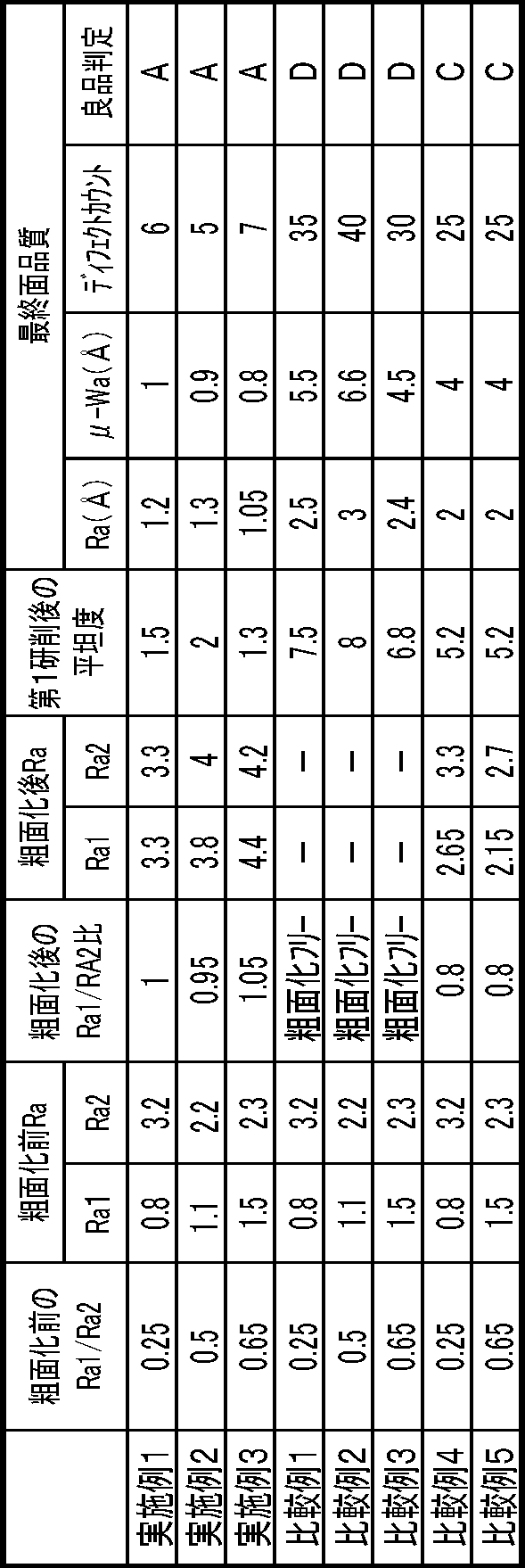
表1に示すように、本発明にかかる製造方法により得られたガラス基板はいずれも第1研削後の平坦度に優れ、バラツキも減少していた。さらに、最終品質においても、表面粗さ(Ra)、ウネリ特性に優れ、欠陥も大幅に減少されていることを示し、ディフェクトカウントも大きく減少していた。よって、本発明の製造方法によれば、非常に優れた品質のガラス基板が得られることが示された。
これに対し、表面研削工程前の粗面化工程を経なかった比較例1~3や、粗面化工程後のRa1/Ra2が0.9未満であった比較例4および5では、第1研削後の平坦度、最終品質の表面粗さ(Ra)、ウネリ特性においていずれも実施例よりも劣っており、ディフェクトカウントが多かった。
(試験例2)
ガラスブランクス成形工程後の板厚を0.90mmとし、最終的に得られた基板の厚みを0.65mmとする以外は、前記試験例1の実施例1~3および比較例1~5と同様の条件で各工程を行い、薄板ガラス基板を作成した。
ガラスブランクス成形工程後の板厚を0.90mmとし、最終的に得られた基板の厚みを0.65mmとする以外は、前記試験例1の実施例1~3および比較例1~5と同様の条件で各工程を行い、薄板ガラス基板を作成した。
得られた実施例4~6および比較例6~10のガラス基板に対し、試験例1と同じ評価方法にて各評価を行った。その評価結果を表2に示す。
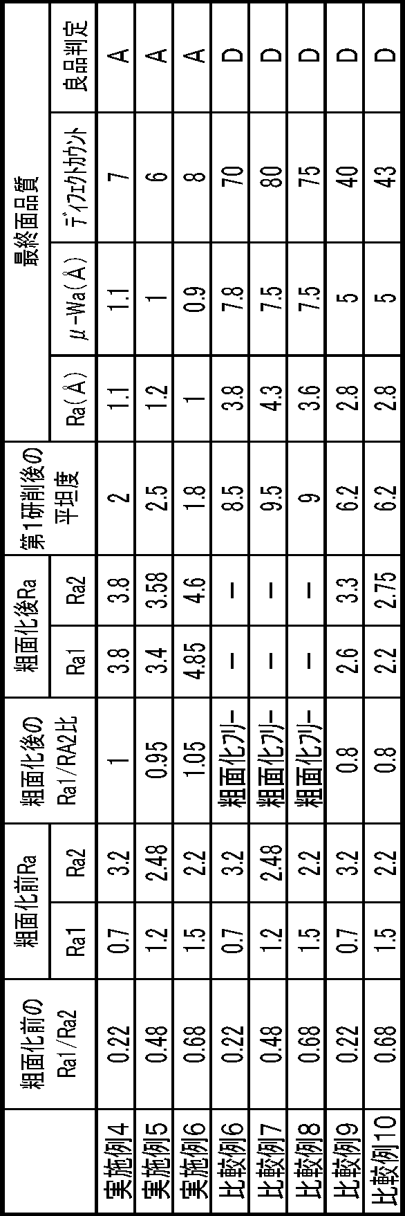
表2に示すように、試験例1と同じく、本発明の製造方法によって得られたガラス基板は、いずれの評価においても比較例よりもはるかに優れていた。
特に、実施例1~3と実施例4~6とを比較すると、ガラスブランクス厚みが1.1mmから0.9mmとなり仕上げの厚みも0.80mmから0.60mmと薄板化し、研削、研磨による取り代が減少したにもかかわらずガラス基板の品質は試験例1同様にきわめて良好であった。これに対し、比較例6~10のガラス基板は薄板化によりいずれの評価品質も試験例1の各比較例に対してさらに悪化していることを考え合わせると、本発明がいかに優れた効果を発揮するかが理解されるであろう。
(試験例3)
ガラスブランクスの粗面化工程を化学的エッチング方法で行う以外は試験例1と同様に行い基板を作成した。
ガラスブランクスの粗面化工程を化学的エッチング方法で行う以外は試験例1と同様に行い基板を作成した。
なお、化学的エッチング方法としては、酸性フッ化アンモニウムを含む処理液にガラス基板を浸漬させた。その浸漬時間、処理液温度、フッ化アンモニウム濃度等の条件を変更することにより、それぞれ表2に記載のRa1/Ra2に変化させた(実施例7~9および比較例11~12)。
得られた実施例7~9および比較例11~12のガラス基板に対し、試験例1と同じ評価方法にて各評価を行った。その評価結果を表3に示す。

表3に示すように、試験例1と同じく、本発明の製造方法によって得られたガラス基板は、いずれの評価においても比較例よりもはるかに優れていた。化学的エッチング方法はガラスブランクス成形で生じている加工ダメージ、傷を削減できる効果をもつため、試験例1のブラスト法により粗面化工程を経たガラス基板と比較すると、ディフェクトカウントがより少なくなり、良品判定においてより優れることが示された。
この出願は、2012年12月27日に出願された日本国特許出願特願2012-284731を基礎とするものであり、その内容は、本願に含まれるものである。
本発明を表現するために、前述において図面等を参照しながら実施形態を通して本発明を適切かつ十分に説明したが、当業者であれば前述の実施形態を変更及び/又は改良することは容易になし得ることであると認識すべきである。したがって、当業者が実施する変更形態又は改良形態が、請求の範囲に記載された請求項の権利範囲を離脱するレベルのものでない限り、当該変更形態又は当該改良形態は、当該請求項の権利範囲に包括されると解釈される。
本発明は、ハードディスク用ガラス基板およびその製造方法の技術分野において、広範な産業上の利用可能性を有する。
Claims (8)
- ハードディスク用ガラス基板の製造方法であって、
ガラスを溶融した後にプレス法で成形したガラスブランクスの表面を粗面化する粗面化工程、及び、その後に行われる表面研削工程を備えること、並びに
前記粗面化工程前のガラスブランクスの上面粗さRa1と下面表面粗さRa2の比(Ra1/Ra2)が0.2~0.7であり、前記粗面化工程によって前記Ra1/Ra2を0.9~1.1に調整することを特徴とする、ハードディスク用ガラス基板の製造方法。 - 前記粗面化工程は、機械的方法又は化学的方法で行われることを特徴とする、請求項1に記載のハードディスク用ガラス基板の製造方法。
- 前記表面研削工程において、ダイヤモンド粒子を固定砥粒としたパッドを用いて前記粗面化工程を経たガラスブランクスを研削することを特徴とする、請求項1又は2に記載のハードディスク用ガラス基板の製造方法。
- 前記表面研削工程において、前記ダイヤモンド粒子の平均粒径が4μm以下であることを特徴とする、請求項3記載のハードディスク用ガラス基板の製造方法。
- 前記粗面化工程において、前記機械的方法としてブラスト処理を行うことを特徴とする請求項2~4のいずれかに記載のハードディスク用ガラス基板の製造方法。
- 前記粗面化工程において、前記化学的方法として薬液によるエッチング作用を使用することを特徴とする請求項2~4のいずれかに記載のハードディスク用ガラス基板の製造方法。
- 前記薬液のpHが7.0~3.0の範囲であることを特徴とする、請求6に記載のハードディスク用ガラス基板の製造方法。
- 前記ガラスブランクスの厚みが1mm以下であることを特徴とする、請求項1~7のいずれかに記載のハードディスク用ガラス基板の製造方法。
Priority Applications (1)
| Application Number | Priority Date | Filing Date | Title |
|---|---|---|---|
| JP2014554137A JP6059739B2 (ja) | 2012-12-27 | 2013-12-25 | ハードディスク用ガラス基板の製造方法 |
Applications Claiming Priority (2)
| Application Number | Priority Date | Filing Date | Title |
|---|---|---|---|
| JP2012-284731 | 2012-12-27 | ||
| JP2012284731 | 2012-12-27 |
Publications (1)
| Publication Number | Publication Date |
|---|---|
| WO2014103295A1 true WO2014103295A1 (ja) | 2014-07-03 |
Family
ID=51020411
Family Applications (1)
| Application Number | Title | Priority Date | Filing Date |
|---|---|---|---|
| PCT/JP2013/007570 Ceased WO2014103295A1 (ja) | 2012-12-27 | 2013-12-25 | ハードディスク用ガラス基板の製造方法 |
Country Status (2)
| Country | Link |
|---|---|
| JP (1) | JP6059739B2 (ja) |
| WO (1) | WO2014103295A1 (ja) |
Cited By (2)
| Publication number | Priority date | Publication date | Assignee | Title |
|---|---|---|---|---|
| WO2019189567A1 (ja) * | 2018-03-30 | 2019-10-03 | Hoya株式会社 | アニール処理用板材、アニール処理用板材の製造方法、及び基板の製造方法 |
| TWI709459B (zh) * | 2019-11-06 | 2020-11-11 | 大陸商福暘技術開發有限公司 | 玻璃基板表面粗糙化的方法 |
Citations (4)
| Publication number | Priority date | Publication date | Assignee | Title |
|---|---|---|---|---|
| JP2008208012A (ja) * | 2007-02-28 | 2008-09-11 | Konica Minolta Opto Inc | ガラス成形体、ガラス基板の製造方法及び情報記録媒体の製造方法 |
| WO2011122303A1 (ja) * | 2010-03-31 | 2011-10-06 | Hoya株式会社 | ガラスブランクの製造方法、磁気記録媒体基板の製造方法および磁気記録媒体の製造方法 |
| WO2012043214A1 (ja) * | 2010-09-30 | 2012-04-05 | コニカミノルタオプト株式会社 | 情報記録媒体用ガラス基板の製造方法および情報記録媒体 |
| JP2012203941A (ja) * | 2011-03-24 | 2012-10-22 | Konica Minolta Advanced Layers Inc | 情報記録媒体用ガラス基板の製造方法 |
-
2013
- 2013-12-25 JP JP2014554137A patent/JP6059739B2/ja active Active
- 2013-12-25 WO PCT/JP2013/007570 patent/WO2014103295A1/ja not_active Ceased
Patent Citations (4)
| Publication number | Priority date | Publication date | Assignee | Title |
|---|---|---|---|---|
| JP2008208012A (ja) * | 2007-02-28 | 2008-09-11 | Konica Minolta Opto Inc | ガラス成形体、ガラス基板の製造方法及び情報記録媒体の製造方法 |
| WO2011122303A1 (ja) * | 2010-03-31 | 2011-10-06 | Hoya株式会社 | ガラスブランクの製造方法、磁気記録媒体基板の製造方法および磁気記録媒体の製造方法 |
| WO2012043214A1 (ja) * | 2010-09-30 | 2012-04-05 | コニカミノルタオプト株式会社 | 情報記録媒体用ガラス基板の製造方法および情報記録媒体 |
| JP2012203941A (ja) * | 2011-03-24 | 2012-10-22 | Konica Minolta Advanced Layers Inc | 情報記録媒体用ガラス基板の製造方法 |
Cited By (7)
| Publication number | Priority date | Publication date | Assignee | Title |
|---|---|---|---|---|
| WO2019189567A1 (ja) * | 2018-03-30 | 2019-10-03 | Hoya株式会社 | アニール処理用板材、アニール処理用板材の製造方法、及び基板の製造方法 |
| CN111886649A (zh) * | 2018-03-30 | 2020-11-03 | Hoya株式会社 | 退火处理用板材、退火处理用板材的制造方法以及基板的制造方法 |
| JPWO2019189567A1 (ja) * | 2018-03-30 | 2021-04-08 | Hoya株式会社 | アニール処理用板材、アニール処理用板材の製造方法、及び基板の製造方法 |
| JP2021177440A (ja) * | 2018-03-30 | 2021-11-11 | Hoya株式会社 | アニール処理用板材、アニール処理用板材の製造方法、及び基板の製造方法 |
| CN111886649B (zh) * | 2018-03-30 | 2022-08-05 | Hoya株式会社 | 退火处理用板材、退火处理用板材的制造方法以及基板的制造方法 |
| JP7228007B2 (ja) | 2018-03-30 | 2023-02-22 | Hoya株式会社 | アニール処理用板材、アニール処理用板材の製造方法、及び基板の製造方法 |
| TWI709459B (zh) * | 2019-11-06 | 2020-11-11 | 大陸商福暘技術開發有限公司 | 玻璃基板表面粗糙化的方法 |
Also Published As
| Publication number | Publication date |
|---|---|
| JP6059739B2 (ja) | 2017-01-11 |
| JPWO2014103295A1 (ja) | 2017-01-12 |
Similar Documents
| Publication | Publication Date | Title |
|---|---|---|
| JP4185266B2 (ja) | 情報記録媒体用基板の製造方法 | |
| CN101950565B (zh) | 信息记录介质用玻璃基板及其制造方法以及磁记录介质 | |
| JP5454180B2 (ja) | 磁気記録媒体用ガラス基板の製造方法及び磁気記録媒体用ガラス基板 | |
| JP5297549B2 (ja) | 磁気ディスク用ガラス基板の製造方法及び磁気ディスクの製造方法 | |
| JP2009099250A (ja) | 磁気ディスク用ガラス基板の製造方法及び磁気ディスクの製造方法 | |
| CN102754152A (zh) | 信息记录媒体用玻璃基板及其制造方法和磁记录媒体 | |
| JP5321594B2 (ja) | ガラス基板の製造方法、および磁気記録媒体の製造方法 | |
| JP2012230748A (ja) | 磁気ディスク用ガラス基板の製造方法 | |
| WO2013145503A1 (ja) | Hdd用ガラス基板の製造方法 | |
| JP6059739B2 (ja) | ハードディスク用ガラス基板の製造方法 | |
| JPWO2010041537A1 (ja) | ガラス基板の製造方法、および磁気記録媒体の製造方法 | |
| WO2010041536A1 (ja) | ガラス基板の製造方法、および磁気記録媒体の製造方法 | |
| JP5297281B2 (ja) | 磁気ディスク用ガラス基板の製造方法 | |
| JP2012216255A (ja) | 磁気ディスク用ガラス基板の製造方法 | |
| WO2014208270A1 (ja) | 情報記録媒体用ガラス基板の製造方法 | |
| JP3156265U (ja) | 研磨用ブラシ、ブラシ調整用治具、磁気ディスク用ガラス基板、および磁気ディスク | |
| WO2011021478A1 (ja) | ガラス基板の製造方法、ガラス基板、磁気記録媒体の製造方法および磁気記録媒体 | |
| JP2007118172A (ja) | 研磨装置、研磨方法、磁気ディスク用ガラス基板および磁気ディスクの製造方法 | |
| JP2007098483A (ja) | 磁気ディスク用ガラス基板および磁気ディスクの製造方法および端面研削装置 | |
| JP2007118173A (ja) | 研磨用ブラシ、ブラシ調整用治具、および研磨用ブラシの調整方法 | |
| JP2007102843A (ja) | 磁気記録媒体用ガラス基板および磁気ディスク | |
| WO2013099083A1 (ja) | Hdd用ガラス基板の製造方法 | |
| JP4723341B2 (ja) | 磁気記録媒体用ガラス基板および磁気ディスクの製造方法 | |
| WO2014156189A1 (ja) | ハードディスク用ガラス基板及びその製造方法 | |
| JP5719030B2 (ja) | 研磨パッドおよび該研磨パッドを用いたガラス基板の製造方法 |
Legal Events
| Date | Code | Title | Description |
|---|---|---|---|
| 121 | Ep: the epo has been informed by wipo that ep was designated in this application |
Ref document number: 13868585 Country of ref document: EP Kind code of ref document: A1 |
|
| ENP | Entry into the national phase |
Ref document number: 2014554137 Country of ref document: JP Kind code of ref document: A |
|
| NENP | Non-entry into the national phase |
Ref country code: DE |
|
| 122 | Ep: pct application non-entry in european phase |
Ref document number: 13868585 Country of ref document: EP Kind code of ref document: A1 |