WO2014097840A1 - 不織布 - Google Patents
不織布 Download PDFInfo
- Publication number
- WO2014097840A1 WO2014097840A1 PCT/JP2013/081996 JP2013081996W WO2014097840A1 WO 2014097840 A1 WO2014097840 A1 WO 2014097840A1 JP 2013081996 W JP2013081996 W JP 2013081996W WO 2014097840 A1 WO2014097840 A1 WO 2014097840A1
- Authority
- WO
- WIPO (PCT)
- Prior art keywords
- nonwoven fabric
- fiber
- fibers
- less
- free end
- Prior art date
- Legal status (The legal status is an assumption and is not a legal conclusion. Google has not performed a legal analysis and makes no representation as to the accuracy of the status listed.)
- Ceased
Links
Images




Classifications
-
- D—TEXTILES; PAPER
- D04—BRAIDING; LACE-MAKING; KNITTING; TRIMMINGS; NON-WOVEN FABRICS
- D04H—MAKING TEXTILE FABRICS, e.g. FROM FIBRES OR FILAMENTARY MATERIAL; FABRICS MADE BY SUCH PROCESSES OR APPARATUS, e.g. FELTS, NON-WOVEN FABRICS; COTTON-WOOL; WADDING ; NON-WOVEN FABRICS FROM STAPLE FIBRES, FILAMENTS OR YARNS, BONDED WITH AT LEAST ONE WEB-LIKE MATERIAL DURING THEIR CONSOLIDATION
- D04H3/00—Non-woven fabrics formed wholly or mainly of yarns or like filamentary material of substantial length
- D04H3/08—Non-woven fabrics formed wholly or mainly of yarns or like filamentary material of substantial length characterised by the method of strengthening or consolidating
- D04H3/14—Non-woven fabrics formed wholly or mainly of yarns or like filamentary material of substantial length characterised by the method of strengthening or consolidating with bonds between thermoplastic yarns or filaments produced by welding
-
- D—TEXTILES; PAPER
- D06—TREATMENT OF TEXTILES OR THE LIKE; LAUNDERING; FLEXIBLE MATERIALS NOT OTHERWISE PROVIDED FOR
- D06C—FINISHING, DRESSING, TENTERING OR STRETCHING TEXTILE FABRICS
- D06C11/00—Teasing, napping or otherwise roughening or raising pile of textile fabrics
-
- D—TEXTILES; PAPER
- D06—TREATMENT OF TEXTILES OR THE LIKE; LAUNDERING; FLEXIBLE MATERIALS NOT OTHERWISE PROVIDED FOR
- D06C—FINISHING, DRESSING, TENTERING OR STRETCHING TEXTILE FABRICS
- D06C3/00—Stretching, tentering or spreading textile fabrics; Producing elasticity in textile fabrics
- D06C3/06—Stretching, tentering or spreading textile fabrics; Producing elasticity in textile fabrics by rotary disc, roller, or like apparatus
Definitions
- the present invention relates to a nonwoven fabric containing long fibers.
- spunbond nonwoven fabrics and nonwoven fabrics with low weights are frequently used because they have high breaking strength, excellent processing suitability, and are economical. Yes.
- the spunbonded nonwoven fabric and the like have a lack of plumpness due to its manufacturing method, and it has been difficult to improve the touch.
- the present applicant has previously proposed a non-woven fabric comprising fibers in which a part of a long fiber is broken, only one end is fixed by a heat-sealed portion, and the free end on the other end is thickened.
- Patent Document 1 According to the nonwoven fabric described in Patent Document 1, although the breaking strength is high, there is a feeling of plumpness as a whole, cushioning properties are improved, and touch is improved.
- Patent Document 2 a surfactant is applied to the back side of the sheet without changing the density of the constituent fibers of the liquid-permeable top sheet, and the back side is more than the front side.
- An absorbent article provided with a liquid-permeable surface sheet imparted with high hydrophilicity on the side is described.
- JP 2012-92475 A Japanese Patent Laying-Open No. 2005-87659
- Patent Document 1 when the nonwoven fabric described in Patent Document 1 is used for a surface sheet of an absorbent article such as a disposable diaper, for example, the viewpoint of quickly transferring the body fluid absorbed by the surface sheet to the absorber side, There is no description regarding the viewpoint that the bodily fluid once absorbed by the absorbent body is difficult to reverse through the surface sheet.
- the improvement in liquid permeability for quickly transferring the absorbed body fluid to the absorber side and the difficulty in returning the fluid that has been absorbed at once and it is difficult to achieve both.
- Patent Document 2 does not describe anything about raising of fibers, and the liquid-permeable surface sheet described in Patent Document 2 is a sheet having poor overall cushioning properties. Moreover, since the liquid-permeable surface sheet described in Patent Document 2 is simply applied with a surfactant without physically changing the density of the constituent fibers, the liquid permeability allows the body fluid to move to the absorber side. It is difficult to improve.
- an object of the present invention is to provide a nonwoven fabric that has improved cushioning properties and is difficult to reverse the liquid while improving the liquid permeability.
- the present invention relates to a hydrophilic nonwoven fabric including a fiber assembly in which long fibers are fixed by a heat-sealing portion.
- a part of the long fiber is broken, one end is fixed by the heat fusion part, and the other end is a free end, and is standing apart from the fiber assembly.
- a fiber having the free end is provided.
- the hydrophilicity of the fiber having the free end is lower than the hydrophilicity of the fiber constituting the fiber assembly.
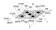
- FIG. 1 is a perspective view showing a nonwoven fabric according to this embodiment of the present invention.
- FIG. 2 is a perspective view showing a fiber having a thick free end portion of the nonwoven fabric shown in FIG.
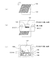
- FIG. 3 is a schematic view showing a method of measuring the tip fiber diameter of the nonwoven fabric shown in FIG.
- FIG. 4 is a schematic view showing a method for measuring the number of fibers raised in the nonwoven fabric shown in FIG.
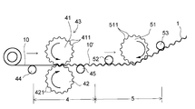
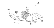
- FIG. 5 is a schematic view showing a preferred production apparatus used in the method for producing a nonwoven fabric of the present invention.
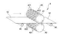
- FIG. 6 is a schematic diagram showing a partially stretched portion provided in the manufacturing apparatus shown in FIG.
- FIG. 7 is an enlarged cross-sectional view of a main part of the partially stretched portion shown in FIG. FIG.
- FIG. 8 is a schematic diagram illustrating a raised processing portion provided in the manufacturing apparatus illustrated in FIG. 5.
- FIG. 9 is a diagram for explaining an example of a usage pattern of the nonwoven fabric of the present invention, and is a developed plan view showing a state in which a pants-type disposable diaper is developed and extended.
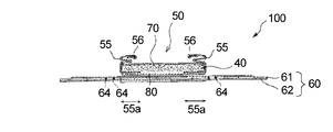
- 10 is a cross-sectional view taken along the line II of FIG.
- the non-woven fabric 1 of the present embodiment (hereinafter also simply referred to as “non-woven fabric 1”) is a hydrophilic non-woven fabric comprising a fiber assembly 11 in which long fibers 2 are fixed by a heat fusion part 3 as shown in FIG. It is.
- a part of the long fiber 2 is broken, and one end portion 20a is fixed by the heat-sealing portion 3 and the other end portion is a free end portion 20b, and is erected away from the fiber assembly 11.
- a fiber 20 (hereinafter also referred to as a fiber 20 having a free end 20b) is provided.
- the nonwoven fabric 1 will be described below with the longitudinal direction of the nonwoven fabric 1 as the Y direction and the width direction of the nonwoven fabric 1 as the X direction, as shown in FIG.
- the MD direction along the fiber orientation direction corresponds to the longitudinal direction (Y direction) depending on the orientation direction of the constituent fibers
- the CD direction perpendicular to the MD direction corresponds to the width direction (X direction).
- the Y direction and the MD direction mean the same direction
- the X direction and the CD direction mean the same direction.
- the nonwoven fabric 1 includes a fiber 20 having a free end portion 20b standing from the fiber assembly 11, and a loop-like fiber 23 (fiber 20) standing up in a loop shape between the heat fusion portions 3 and 3 described later.
- Fiber 23 is referred to as “raising fiber”) and fiber assembly 11 composed of non-raising fibers other than “raising fiber”.
- the fiber assembly 11 includes a fiber 20 having a free end 20b standing from the fiber assembly 11, and a loop-like fiber 23 standing in a loop between the heat-sealing portions 3 and 3 described later. Except for brushed fibers.
- the non-woven fabric 1 of the present embodiment will be described in detail.
- the non-woven fabric 1 is formed based on a hydrophilic non-woven fabric 10 in which a web made of long fibers 2 is intermittently fixed by a heat fusion part 3.
- the original nonwoven fabric (raw material nonwoven fabric) 10 is a nonwoven fabric before breaking a part of the long fibers 2.
- the “long fiber” has a fiber length of 30 mm or more, and the raw nonwoven fabric 10 is preferably a so-called continuous long fiber having a fiber length of 150 mm or more because a nonwoven fabric 1 having high breaking strength can be obtained. .
- Examples of the raw material nonwoven fabric 10 include a spunbond nonwoven fabric, a laminated nonwoven fabric of a spunbond layer and a meltblown layer, a heat roll nonwoven fabric by a card method, and the like.
- Examples of the laminated nonwoven fabric include spunbond-spunbond laminated nonwoven fabric, spunbond-spunbond-spunbond laminated nonwoven fabric, spunbond-meltblown-spunbond laminated nonwoven fabric, spunbond-spunbond-meltblown-spunbond laminated nonwoven fabric, etc. Can be mentioned.
- the hydrophilic raw material nonwoven fabric 10 is obtained by performing a hydrophilization treatment by attaching a hydrophilizing agent to the surface of the constituent fiber of the non-woven fabric or kneading the hydrophilizing agent into the constituent fiber. That is, the hydrophilic raw material nonwoven fabric 10 is formed by hydrophilizing the hydrophobic long fibers 2.
- Hydrophilic agents include anionic, cationic, amphoteric and nonionic surfactants such as carboxylate anionic surfactants, sulfonate anionic surfactants, and sulfate ester salts.
- Anionic surfactants such as phosphate anionic surfactants (especially alkyl phosphate salts); sorbitan fatty acid esters, diethylene glycol monostearate, diethylene glycol monooleate, glyceryl monostearate, Polyhydric alcohol monofatty acid esters such as glyceryl monooleate and propylene glycol monostearate, fatty acid amides such as oleic acid amide, stearic acid amide and erucic acid amide, N- (3-oleyloxy-2-hydroxypropyl) diethanolamine, polyoxy Ethylene hydrogenated castor oil, polyoxyethylene sorbit beeswax, polyoxyethylene sorbitan sesquistearate, polyoxyethylene monooleate, polyoxy
- the amount of the hydrophilizing agent in the nonwoven fabric 1 is preferably 0.1% by weight or more and 20% by weight or less with respect to the weight of the nonwoven fabric 1 from the viewpoint of achieving both the liquid passing time and the liquid return amount. More preferably, it is at least 5% by weight.
- additives such as a fiber colorant, an antistatic property agent, and a softening agent may be added to the raw material nonwoven fabric 10.
- a softening agent for example, a wax emulsion, a reactive softening agent, a silicone compound, a surfactant and the like can be used.
- medical agent can be added to a softening agent as a secondary additive (small component) as needed.
- the nonwoven fabric 1 formed based on the nonwoven fabric 10 has a good touch, little fluff loss, low surface friction on the surface, and high breaking strength.
- the softener is preferable in terms of increasing the effect when used in combination with a random copolymer, which will be described later, as a resin of the constituent fibers of the raw nonwoven fabric 10, and the slime feeling due to the random copolymer in the nonwoven fabric 1 formed from the raw nonwoven fabric 10. This is particularly preferable in that a softening agent can be used to reduce the occurrence of water and a smooth skin can be obtained.
- the raw material nonwoven fabric 10 is formed of a laminated nonwoven fabric of a spunbond layer and a meltblown layer
- the spunbond layer of the laminated nonwoven fabric comprises a plurality of layers, for example, a spunbond-meltblown-spunbond laminated nonwoven fabric.
- a spunbond-spunbond-meltblown-spunbond laminated nonwoven fabric etc., it is preferable to knead the above softener only in one spunbond layer, and knead all spunbond layers. Also good.
- the non-woven fabric 1 When a softening agent is kneaded into a single layer of spunbond, if the layer is subjected to the processing described below, the non-woven fabric 1 having a good touch when touching the skin and having a high breaking strength can be obtained. preferable. As described above, the nonwoven fabric 1 is more suitable than the raw material nonwoven fabric 10 formed of the laminated nonwoven fabric of the spunbond layer and the meltblown layer, in terms of the feel when contacting the skin and the amount of wetback. It is preferable to form based on the raw material nonwoven fabric 10 which consists of a bond nonwoven fabric simple substance.
- the constituent fibers of the raw material nonwoven fabric 10 mainly contain a thermoplastic resin, and examples of the thermoplastic resin include polyolefin resins, polyester resins, polyamide resins, acrylonitrile resins, vinyl resins, and vinylidene resins.
- the polyolefin resin include polyethylene, polypropylene, and polybuden.
- the polyester resin include polyethylene terephthalate and polybutylene terephthalate. Nylon etc. are mentioned as a polyamide-type resin.
- the vinyl resin include polyvinyl chloride.
- the vinylidene resin include polyvinylidene chloride.
- a composite fiber can also be used as the long fibers constituting the raw material nonwoven fabric 10. Side-by-side fibers, core-sheath fibers, core-sheath fibers having eccentric crimps, split fibers, and the like can be used as the composite fibers.
- a composite fiber it is preferable that a core-sheath fiber having a core made of polypropylene and a sheath made of polyethylene is used because a soft nonwoven fabric 1 can be obtained.
- the fiber diameter of the long fibers 2 is preferably 5 ⁇ m or more and 30 ⁇ m or less, and more preferably 10 ⁇ m or more and 20 ⁇ m or less before processing described later.
- the raw material nonwoven fabric 10 is preferably formed from a polypropylene resin which is a polyolefin resin from the viewpoint of spinnability.
- the polypropylene resin is smooth, and from the viewpoint of improving the touch when it comes into contact with the skin, and from the viewpoint of easy breakage, at least 5% by mass of any one of random copolymer, homopolymer and block copolymer is 100 It is preferable that the resin contains no more than 25% by mass, more preferably no less than 25% and no more than 80% by mass. Further, these copolymers and homopolymers may be mixed, or other resins may be mixed. However, it is difficult to break the yarn during molding, and mixing of polypropylene homopolymer and random copolymer is preferable.
- a copolymer obtained by copolymerizing ethylene or ⁇ -olefin as a random copolymer based on a propylene component is preferable, and an ethylene-propylene copolymer resin is particularly preferable.
- the polypropylene resin is preferably a resin containing 5% by mass or more of an ethylene propylene copolymer resin, and more preferably a resin containing 25% by mass or more.
- the ethylene / propylene copolymer resin preferably contains an ethylene concentration of 1% by mass or more and 20% by mass or less, and particularly has no stickiness, is easy to stretch when stretched, has little fluff loss, and maintains the breaking strength.
- the ethylene concentration is 3% or more and 8% or less.
- a polypropylene resin it is preferable that it is resin containing 50 mass% or more of recycled polypropylene resins from an environmental viewpoint, and it is still more preferable that it is resin containing 70 mass% or more. The same applies when the nonwoven fabric 1 is formed based on a laminated nonwoven fabric of a spunbond layer and a meltblown layer.
- the nonwoven fabric 1 formed from the raw material nonwoven fabric 10 is inexpensive and provides a good feel when touched to the skin, and has a basis weight of 5 g / m 2 or more and 100 g / m from the viewpoint of processing suitability. It is preferably 2 or less, and more preferably 5 g / m 2 or more and 25 g / m 2 or less.
- the nonwoven fabric 1 configured as described above has a bulk softness of preferably 10 cN or less, more preferably 5.9 cN or less, and 0.5 cN or more from the viewpoint of excellent touch.
- the raw material nonwoven fabric 10 has a bulk softness of preferably 15 cN or less, more preferably 10 cN or less, and preferably 3 cN or more, from the viewpoint that a soft material is obtained and the touch is excellent. More preferably, it is 5 cN or more. Specifically, it is preferably 3 cN or more and 15 cN or less, and more preferably 5 cN or more and 10 cN or less. Bulk softness is measured by the following measurement method.
- the bulk softness of the nonwoven fabric 1 is obtained by cutting the nonwoven fabric 1 in the Y direction (longitudinal direction) 150 mm and the X direction (width direction) 30 mm in a 22 ° C. and 65% RH environment, and using a stapler in a ring shape with a diameter of 45 mm. Stop the edges at the top and bottom. At this time, the stapler core is elongated in the Y direction (longitudinal direction).
- the ring is placed in a cylindrical shape on the sample stage, and the compression speed is 10 mm on a flat plate substantially parallel to the stage from above. Measure the maximum load when compressed at a speed of / min, and use it as bulk softness.
- a tensile tester for example, Tensilon tensile tester “RTA-100” manufactured by Orientec Co., Ltd.
- the fiber 20 having the free end 20b standing upright away from the fiber assembly 11 has a lower hydrophilicity than the fibers constituting the fiber assembly 11. ing.
- the fiber 20 having the free end portion 20b is more hydrophobic than the fiber constituting the fiber assembly 11, and the contact angle with respect to pure water is the fiber 20 constituting the fiber assembly 11. It is higher than the fiber.
- the contact angle with respect to the pure water of the fiber 20 having the free end 20b is preferably higher than 80 °, and more preferably higher than 85 °, from the viewpoint of making it difficult to reverse the body fluid once absorbed. 90 ° or more is particularly preferable.
- the contact angle of the fibers constituting the fiber assembly 11 with respect to pure water is preferably lower than 90 °, more preferably lower than 85 °, and more preferably 80 ° or less from the viewpoint of quickly transferring body fluid to the absorber side. Particularly preferred.
- the contact angle of the fiber 20 having the free end portion 20b is different from the contact angle of the fiber constituting the fiber assembly 11 by 5 ° or more from the viewpoint of achieving both liquid permeability and liquid return difficulty. It is preferably high, and more preferably a difference of 10 ° or more.
- there is a difference in the contact angle value that is, the difference in hydrophilicity means that the contact angle value measured by the measurement method has an opening of 3 ° or more.
- the specific method for measuring the contact angle is as follows.
- a contact angle meter MCA-J manufactured by Kyowa Interface Science Co., Ltd. is used for the measurement of the contact angle.
- the contact angle is measured immediately using the contact angle meter.
- the contact angle of the fiber 20 having the free end portion 20b is measured at a portion where the fiber 20 having the free end portion 20b is cut, and the contact angle of the non-raised fiber constituting the fiber assembly 11 is determined in the nonwoven fabric 1.
- the fiber 20 having the free end and the fiber 23 on the loop standing in a loop shape between the heat fusion parts 3 and 3 are removed, that is, the part of the fiber assembly 11 cut out is measured.
- Each measurement is performed at five or more locations, and the average value thereof is taken as the contact angle.
- the measurement is performed in an environment of 22 ° C. and 65% RH.
- the nonwoven fabric 1 is preferably 30% or more, in terms of the ratio of fibers having a fiber-to-fiber distance of 150 ⁇ m or more and 300 ⁇ m or less among the fibers constituting the nonwoven fabric 1, from the viewpoint of quickly transferring body fluid to the absorbent side. More preferably, it is more preferably 40% or more.
- the interfiber distance of the nonwoven fabric 1 is measured using a mercury porosimeter (Shimadzu Corporation) in accordance with the mercury intrusion method (JIS R 1655).
- the mercury intrusion method is a method for obtaining information on the physical shape of the fiber assembly 11 by measuring the size and the volume between the fibers constituting the fiber assembly 11 (interfiber distance).
- the principle of the mercury intrusion method is to apply pressure to mercury and inject it into the constituent fibers of the nonwoven fabric 1, which is the object to be measured, and measure the relationship between the pressure applied at that time and the volume of mercury that has been pushed in (intruded) It is in.
- the measuring method of the interfiber distance of the nonwoven fabric 1 using a mercury porosimeter is demonstrated.
- the nonwoven fabric 1 is cut into 24 mm ⁇ 15 mm. A total of three sheets are cut, and these cut samples are set in a sample cell of a mercury porosimeter (Shimadzu Corporation) so as not to overlap each other, and the pore volume is measured.
- the pore volume measurement method by mercury porosimetry is as follows. That is, the pressure applied to mercury is gradually changed, the volume of mercury pushed into the pores at that time, in other words, the pore volume is measured, and the pore diameter (interfiber distance) D converted according to the following equation (1): Draw the relationship between and the pore volume.
- the hole diameter ( ⁇ m) at this time is defined as the interfiber distance ( ⁇ m).
- D ⁇ 4 ⁇ cos ⁇ / P (1)
- the hole diameter (distance between fibers) is D
- the surface tension of mercury is ⁇
- the contact angle is ⁇
- the pressure is P.
- the surface tension of mercury is 482.536 dyn / cm
- the contact angle is 130 °
- the mercury pressure is 0 to 60000 psia.
- the total pore diameter (interfiber distance) over which the pore diameter (interfiber distance) ranges from 0 ⁇ m to 500 ⁇ m is defined as the total capacity.
- the ratio of the capacity of the pore diameter (interfiber distance) of 150 ⁇ m or more and 300 ⁇ m or less to the total capacity is determined.
- the measurement is performed three times, and the average value thereof is set to a ratio (%) in which the interfiber distance is 150 ⁇ m or more and 300 ⁇ m or less.
- the measurement is performed in an environment of 22 ° C. and 65% RH.
- the nonwoven fabric 1 preferably has a breaking strength value of 5.0 N / 50 mm or more and 8.0 N / 50 mm or more and 30.0 N / 50 mm or less from the viewpoint of prevention of breakage during use and processing suitability. More preferably it is.
- the value of the breaking strength of the raw material nonwoven fabric 10 is preferably 7.0 N / 50 mm or more from the viewpoint of setting the breaking strength in the nonwoven fabric 1 to the above value, and is 10.0 N / 50 mm or more and 50.0 N / 50 mm or less. More preferably it is.
- the value of the breaking strength of the produced nonwoven fabric 1 is less likely to be lower than the value of the breaking strength of the raw material nonwoven fabric 10 as compared with other raising methods. It is preferable that the breaking strength of the nonwoven fabric 1 and the original raw material nonwoven fabric 10 satisfy the above range in the CD direction.
- the ratio of the breaking strength between the nonwoven fabric 1 and the original raw material nonwoven fabric 10 is preferably 0.5 or more and 1.0 or less, 0.7 More preferably, it is 1.0 or less.
- the breaking strength is measured by the following method.
- a rectangular measurement piece having a size of 200 mm in the CD direction and 50 mm in the MD direction is cut out from the nonwoven fabric 1 or the raw material nonwoven fabric 10 (for example, spunbond nonwoven fabric).
- the cut out rectangular measurement piece is used as a measurement sample.
- the measurement sample is attached to a chuck of a tensile tester (for example, Tensilon tensile tester “RTA-100” manufactured by Orientec Co., Ltd.) so that the CD direction is the tensile direction.
- the distance between chucks is 150 mm.
- the measurement sample is pulled at 300 mm / min, and the maximum load point until the sample breaks is defined as the breaking strength in the CD direction. Further, a rectangular measurement piece having a size of 200 mm in the MD direction and 50 mm in the CD direction is cut out and used as a measurement sample. The measurement sample is attached to a chuck of a tensile tester so that the MD direction is the tensile direction. The breaking strength in the MD direction is obtained by the same procedure as the method for measuring the breaking strength in the CD direction described above.
- the non-woven fabric 1 is also characterized by a good touch (texture) when the surface provided with the fibers 20 having the free ends 20b comes into contact with the skin.
- a good touch texture
- many characteristic values representing the touch are known, and in particular, the characteristic values in KES manufactured by Kato Tech Co., Ltd. are generally known (reference: texture evaluation standardization and analysis (second edition), author) Issued by Katsuo Kawabata, July 10, 1980).
- LC linearity of compression load-compression strain curve
- WC compression work
- RC compression resilience
- the load when a human touches the absorbent article is about 0.98 cN / cm 2 (1.00 gf / cm 2 ), which is very light and feels the touch.
- the characteristic value in a small range is considered useful, and the load is between 0.29 cN / cm 2 (0.3 gf / cm 2 ) and 0.98 cN / cm 2 (1 gf / cm 2 ) and at that time A new characteristic value was found from the amount of deformation.
- This characteristic value is shown as a numerical value that clearly represents the difference in feel between the spunbonded nonwoven fabric and the air-through nonwoven fabric, and the nonwoven fabric can be expressed as a new characteristic value that represents the feel of the spunbonded nonwoven fabric.
- the compression characteristic value at the time of a minute load is defined as a new characteristic value representing the touch.
- the measurement was performed in an environment of 22 ° C. and 65% RH.
- KES FB3-AUTO-A (trade name) manufactured by Kato Tech Co., Ltd. was used for the measurement of the data used as the basis for calculating the compression characteristic value under a minute load.
- Three pieces of nonwoven fabric 1 are cut into 20 cm ⁇ 20 cm to prepare measurement samples. Next, one of the measurement samples is placed on the test stand with the raised surface (the surface provided with the fiber 20 having the free end 20b) facing upward (if not raised or both surfaces are raised) If so, measure both and use the smaller one).
- compression is performed between steel plates having a circular plane with an area of 2 cm 2 .
- the compression rate is 20 ⁇ m / sec
- the maximum compression load is 9.80 cN / cm 2 (10.0 gf / cm 2 )
- the recovery process is also measured at the same rate.
- the amount of displacement between the steel plates is x (mm)
- the load is y (cN / cm 2 )
- the value of x increases as it is compressed.
- the compression characteristic value at the minute load is calculated by extracting the deformation amount of the thickness at the minute load from the measured data (x, y).
- the first load that is not a recovery process is a load between 0.29 cN / cm 2 (0.30 gf / cm 2 ) and 0.98 cN / cm 2 (1.00 gf / cm 2 ), and at that time
- the amount of deformation data is extracted, an approximate straight line is obtained for the relationship between x and y by the least square method, and the slope at that time is defined as the characteristic value (unit (cN / cm 2 ) / mm).
- Three points are measured with one measurement sample. A total of 9 points of 3 samples are measured.
- the characteristic values at each of the nine locations are calculated, and the average value is set as the compression characteristic value when the nonwoven fabric is subjected to a minute load.
- the compression characteristic value at the time of a minute load has a correlation with the touch, and particularly has a strong correlation when the original raw material nonwoven fabric 10 is the same.
- the compression characteristic value of the original raw material nonwoven fabric 10 (for example, spunbonded nonwoven fabric) having a normal basis weight of 5 g / m 2 or more and 25 g / m 2 or less, which is not subjected to the processing described later, is 19.6 (cN / cm 2 ) / mm (20.0 (gf / cm 2 ) / mm) to 29.4 (cN / cm 2 ) / mm (30.0 (gf / cm 2 ) / mm)
- the non-woven fabric 1 obtained by subjecting the original raw material nonwoven fabric 10 (for example, spunbonded nonwoven fabric) to the processing described below is easily crushed and the surface is less than 17.6 (cN / cm 2 ) / mm (18.0 (gf / cm 2 ) / mm) or less.
- the compression characteristic value of the nonwoven fabric 1 obtained by processing the original raw material nonwoven fabric 10 (for example, spunbond nonwoven fabric) of 5 g / m 2 or more and 25 g / m 2 or less is 17.6 (cN / cm 2 ) / mm (18.0 (gf / cm 2 ) / mm) or less and 14.7 (cN / cm 2 ) / mm (15.0 (gf / cm 2 ) / mm or less) are preferred, from the viewpoint becomes soft near fluffy air-through nonwoven fabric, 9.80 (cN / cm 2) / mm (10.0 (gf / cm 2) / mm) it is further preferred to be less.
- the lower limit of the compression characteristic value of the nonwoven fabric 1 obtained by processing the original raw material nonwoven fabric 10 for example, spunbond nonwoven fabric
- the raw material nonwoven fabric 10 for example, spunbond nonwoven fabric
- the raw material nonwoven fabric 10 having a low basis weight of 5 g / m 2 or more and 25 g / m 2 or less is used in this way without significantly reducing the breaking strength. It has been difficult to perform processing so as to have various characteristic values.
- the area of each heat-fused portion 3 is preferably 0.05 mm 2 or more and 10 mm 2 or less from the viewpoint of touch and processing suitability, and 0.1 mm 2 or more and 1 mm 2. More preferably, it is as follows.
- the number of heat-sealing portions 3 is preferably 10 / cm 2 or more and 250 / cm 2 or less, and more preferably 35 / cm 2 or more and 65 / cm 2 or less.
- the distance between the centers of the heat fusion parts 3 adjacent in the CD direction is preferably 0.5 mm or more and 10 mm or less, more preferably 1 mm or more and 3 mm or less, and the heat fusion part adjacent in the MD direction.
- the distance between the centers of the three is preferably 0.5 mm or more and 10 mm or less, and more preferably 1 mm or more and 3 mm or less.
- the heat fusion part 3 was intermittently formed by thermocompression bonding using embossing (with an embossed convex roller and a flat roll), ultrasonic fusion, or intermittent fusion by applying hot air intermittently. Things. Among these, the thermocompression bonding is preferable in that the fiber is easily broken.
- fusion part 3 is not restrict
- the ratio of the total area of the heat fusion part 3 to the surface area of one surface of the nonwoven fabric 1 is preferably 5% or more and 30% or less, and it is 10% or more and 20% or less because it is difficult to produce pills. Further preferred.
- the nonwoven fabric 1 is formed based on, for example, a spunbonded nonwoven fabric composed of long fibers 2, and a fiber 20 (a part of the fiber 2 is broken and only one end portion 20 a is fixed by the heat-sealed portion 3 ( A fiber 20) having a free end 20b is formed, and the fiber 20 includes a fiber 21 having a thick free end 20b (see FIG. 1). It is preferable that the tip is thick, and that the cross section at the tip is flat (ellipse or crushed shape). Thereby, the fiber which has raised the soft tip is obtained, and the nonwoven fabric with little irritation
- the fiber 20 in which only one end portion 20a is fixed by the heat-sealing portion 3 has a thick fiber 21 and free end portion 20b in which the free end portion 20b on the other end side is thick. It consists of fibers 22 that are not.
- the “free end portion” means the “other end portion” of the fiber 20 in which only one end portion 20 a is fixed by the heat fusion portion 3, in other words, the “tip portion”. Whether or not the free end portion 20b is thick is determined by measuring the fiber diameter by the following measurement method and calculating the increasing rate of the tip fiber diameter.
- the fiber diameter of the fiber 21 (the diameter 21b of the fiber 21 at the free end 20b) at the thickest position in the region is measured.
- the tip When the tip is flat, the tip may not appear thick depending on the observation angle, but even in that case, the obtained photograph is measured as it is.
- the fiber 20 (only the one end part 20b is fixed by the heat sealing
- the ratio of the fibers 21 having the thick free ends 20b in the thick fibers 21 and the fibers 22) in which the free ends 20b are not thick is preferably 20% or more, more preferably 30% or more. Is more preferable, and 40% or more is particularly preferable.
- the ratio of the fibers 21 in which the free end portion 20b is thick is determined from the SEM image obtained by enlarging the randomly selected ten fibers 20 by about 750 times in the fiber diameter measurement method described above. Each is calculated, and the ratio of the fibers 21 whose free ends 20b are thick is calculated.
- the nonwoven fabric 1 has loop-like fibers 23 that stand in a loop between the heat-sealing portions 3 and 3.
- the standing “loop-like fiber 23” means that when the fiber diameter measurement method described above is observed as shown in FIG. 3C, the other end portion does not have the free end portion 20b and the folded line It means a fiber standing up from Z by 0.5 mm or more.
- the loop-like fiber 23 refers to the standing loop-like fiber.
- the fiber constituting the nonwoven fabric 1 is composed of a fiber 21 having a thick free end 20b and a fiber 22 having a thick free end 20b, and only one end 20a is a heat-sealed portion.
- the fiber assembly 11 is mainly formed of the fibers that are not raised. The average fiber diameter of the constituent fibers of the fiber assembly 11 is selected and cut out at random from 10 fibers that are not raised, and the average value is determined in the same manner based on the above-described [Fiber Diameter Measurement Method].
- the nonwoven fabric 1 does not get caught on the skin when it comes into contact with the skin. From the viewpoint of reducing discomfort and improving the touch, only the one end portion 20a of the fibers constituting the nonwoven fabric 1 is formed by the heat fusion portion 3.
- the ratio of the loop-like fibers 23 to the total number of the fixed fibers 20 (fibers 20 having the free ends 20b) and the loop-like fibers 23 is preferably less than 50%, and 45% or less. More preferably, it is particularly preferably 40% or less.
- the ratio of the loop-like fibers 23 is determined by randomly selecting 10 fibers from the SEM image enlarged approximately 50 times in the above-described fiber diameter measurement method, and from the 10 fibers randomly selected, the free end portion 20b.
- Fiber 20 (fiber 21 having a thick free end 20b, fiber 22 having a free free end 20b) and loop-like fiber 23 are extracted, and the total number of fibers 21, 22 and 23
- the ratio of the fibers 23 (loop-like fibers) is calculated and obtained.
- a measured value calculates
- the loop-like fiber 23 is counted as one.
- the nonwoven fabric 1 from the viewpoint of including a fiber having a relatively high degree of freedom, the gap between the fibers is filled, the surface roughness is small and smooth, and the touch when touching the skin is improved.
- the fiber diameter distribution (dispersion degree) is preferably as wide as possible, but from the viewpoint of the touch, a satisfactory effect can be obtained if it is 0.33 or more, and it is more satisfactory if it is 0.35 or more. The effect to be obtained is obtained.
- the fiber diameter distribution (dispersion degree) is not particularly limited, but is preferably 100 or less. More preferably, the fiber diameter distribution (dispersion degree) is preferably 0.35 or more and 0.9 or less.
- the fiber diameter distribution (dispersion degree) here means the fiber diameter distribution (dispersion degree) of all the fibers constituting the nonwoven fabric 1, and only one end portion 20 a is fixed by the heat-sealing portion 3.
- the fiber 20, the loop-shaped fiber 23, and both ends thereof are fixed by the heat-sealing portion 3, and the entire distribution of fibers that are not raised in a loop shape (fibers that are not affected by processing described later).
- the fiber diameter distribution (dispersion degree) is measured by the following method.
- the fiber of the meltblown layer is not selected, and only the fiber of the spunbond layer is selected.
- Ten fiber diameters are measured on one aluminum sample stage as described above, the average value d ave is obtained from the measured ten fiber diameters d 1 to d 10 , and the obtained ten fiber diameters are obtained. From the d 1 to d 10 and the average value d ave , the fiber diameter distribution of 10 randomly selected fibers is obtained by the following equation (3).
- the measurement unit is ⁇ m, and measurement is performed with a resolution of 0.1 ⁇ m.
- the distribution of the fiber diameters of 10 fibers is made for the above-mentioned aluminum sample stage for each nonwoven fabric 1 and the average value of the distributions of the fiber diameters of the 10 fibers obtained at each position (the following formula) (See (4)) is the fiber diameter distribution in the nonwoven fabric 1.
- the VARPA function in spreadsheet software excel2003 of Microsoft Corporation is used for calculation of the fiber diameter distribution of 10 fibers.
- Fiber diameter distribution of 10 fibers [(d 1 ⁇ d ave ) 2 + (d 2 ⁇ d ave ) 2 +... (D 10 ⁇ d ave ) 2 )] / 10
- Fiber diameter distribution (dispersion degree) in the nonwoven fabric 1 (total sum of fiber diameter distributions of 10 fibers obtained by the above formula (3)) / 6 (4)
- the nonwoven fabric 1 is preferably 8 fibers / cm or more, more preferably 12 fibers / cm or more from the viewpoint of improving cushioning properties and improving the touch when in contact with the skin. It is more preferable.
- the raised fibers in the nonwoven fabric 1 are fibers 20 having free ends 20b (fibers 21 having free ends 20b are thick, fibers 22 having free ends 20b are not thick), And the loop-like fiber 23 is included.
- the upper limit of the raised fibers is 100 fibers / cm or less from the viewpoint of obtaining sufficient breaking strength, and more preferably 40 fibers / cm or less from the point of appearance that they are not fluffy.
- the raised fibers are measured by the following measurement method.
- the “nonwoven fabric provided with raised fibers” refers to a nonwoven fabric in which the number of raised fibers is 5 / cm or more in the following measurement method.
- FIG. 4 is a schematic view showing a method for measuring the number of fibers raised among the fibers constituting the nonwoven fabric 1 in an environment of 22 ° C. and 65% RH.
- a measurement piece of 20 cm ⁇ 20 cm is cut out from the nonwoven fabric to be measured with a sharp razor, and as shown in FIG. 4A, the measurement sample 104 is formed by mountain folding on the raised surface of the measurement piece.
- this measurement sample 104 is placed on an A4 size black mount, and as shown in FIG. 4B, an A4 size black mount in which holes 107 of 1 cm in length and 1 cm in width are further formed. Put on.
- FIG. 4 an A4 size black mount in which holes 107 of 1 cm in length and 1 cm in width are further formed.
- the fold 105 of the measurement sample 104 is arranged so that it can be seen from the hole 107 of the upper black mount.
- “Kenran (black) continuous weight 265 g” of Fuji Kyowa Paper Co., Ltd. was used for both mounts. Thereafter, a weight of 50 g is placed on each side of the upper mount hole 107 at a position spaced 5 cm outward along the fold line 105 so that the measurement sample 104 is completely folded.
- FIG. 4 (c) the inside of the mount hole 107 is observed at a magnification of 30 times using a microscope (VHX-900 manufactured by KEYENCE), and the measurement sample 104 has a fold 105 to 0.
- the number of raised fibers for example, there is a fiber that crosses the virtual line 108 that is 0.2 mm above the fold 105 twice, such as a fiber 106a shown in FIG.
- the fiber counts as two.
- the number of raised fibers is 6.
- the nonwoven fabric 1 is a fiber that is raised (a fiber that crosses the imaginary line 108 and includes a fiber 20 having a free end 20b and a loop-like fiber 23 from the viewpoint of improving the touch when touching the skin. ) Of the surface fibers of the same surface that are not brushed (fibers that do not cross the imaginary line 108 and do not reach the imaginary line 108, that is, fibers that are not brushed that constitute the fiber assembly 11). It is preferably smaller than the average fiber diameter.
- the average fiber diameter refers to a fiber diameter obtained by measuring the fiber diameters of 12 raised fibers and 12 non-raised fibers with a microscope (such as an optical microscope or SEM).
- the average fiber diameter of the raised fibers is preferably 98% or less and 40% or more of the average fiber diameter of the non-raised fibers, and more preferably 96% or less and 70% or more because it is excellent in the touch.
- the average fiber diameter of the fibers 20 having the free end portion 20b and the average fiber diameter of the loop-shaped fibers 23 are both larger than the average fiber diameter of the fibers constituting the fiber assembly 11 (fibers not raised). It is preferably small, and preferably 98% or less and 40% or more of the fiber diameter of the non-raised fiber, more preferably 96% or less and 70% or more, because it is excellent in the touch.
- the nonwoven fabric 1 has a number of raised fibers (fibers including free ends 20b and fibers including loop-like fibers 23) of 8 / cm or more and is raised. It is preferable that the raised height of the fibers is 1.5 mm or less. Thereby, cushioning property improves and the absorbent article which the touch improved is obtained. From the viewpoint of being less prone to fluff and difficult to remove, it is more preferable that the raised height of the raised fiber is 1.0 mm or less. On the other hand, if it is 0.2 mm or more, a good touch can be obtained. Furthermore, the raised height is preferably 0.5 mm or more in that the amount of wetback in the absorption characteristics of body fluid is reduced.
- the raised height is more preferably 1.0 mm or less from the viewpoint that it is difficult to cling to the skin and feel is preferable. Moreover, it is good at the point that the thing of the improvement of cushioning property and a quick absorption speed of a bodily fluid is obtained that the fiber which has fluffed is 15 pieces / cm or more. Further, if the height of the raised fiber exceeds 5 mm, it becomes a fuzzy appearance, and if it is rubbed during use, it becomes fuzzy or fluffy, which is not preferable.
- the raised height means the height of the fiber in the natural state without pulling the fiber during measurement, unlike the length of the fiber. When the value of the length of the raised fiber is large or the rigidity of the fiber is high, the raised height of the raised fiber tends to increase. The raised height of the raised fiber is measured by the following measuring method.
- the raising height of the raised fibers is measured at the same time as measuring the number of raised fibers (fibers having free ends 20b and fibers including loop-like fibers 23). Specifically, as shown in FIG. 4C, the inside of the hole 107 of the mount is observed, and a line is drawn in parallel from the crease 105 to a point where fibers that are raised every 0.05 mm do not intersect. Next, compared to the number of raised fibers measured as described above (determined from the imaginary line 108 above 0.2 mm), select a parallel line that halves the fibers that intersect the parallel line, and from there The distance to the crease is the raised height. The above-mentioned operation is measured for three sheets of the nonwoven fabric to be measured, and the average of three places per sheet and three places in total is taken as the raised height of the raised fibers.
- the bulk softness of the non-woven fabric 1 is 8.0 cN or less, so that a flexible material can be obtained when it comes into contact with the skin. It is preferable at the point which is excellent in the touch. Furthermore, it is preferable that it is 0.5 cN or more and 3.0 cN or less from the point which becomes a supple thing like a baby's or infant's vestibule. Bulk softness is measured by the following measurement method.
- the bulk softness of the nonwoven fabric 1 is 150 mm in the MD direction and 30 mm in the CD direction, and is stapled into a ring shape with a diameter of 45 mm at two upper and lower ends. At this time, the stapler core is elongated in the MD direction.
- a tensile tester for example, Tensilon tensile tester “RTA-100” manufactured by Orientec Co., Ltd.
- the ring is placed in a cylindrical shape on the sample stage, and the compression speed is 10 mm on a flat plate substantially parallel to the stage from above. Measure the maximum load when compressing at a speed of / min.
- a ring is produced by changing the MD direction and the CD direction, and the bulk softness in the MD direction is similarly measured.
- Two rings each in the MD direction and the CD direction are prepared and measured, and the average value of the CD direction and the MD direction is defined as the bulk degree of the nonwoven fabric 1.
- the manufacturing apparatus preferably used in the method for manufacturing the nonwoven fabric 12 is roughly divided into a pre-processing section 4 and a raised processing section 5 disposed on the downstream side of the pre-processing section 4.
- This pre-processed portion is also referred to as a partially stretched processed portion.
- the pre-processing unit 4 includes a steel matching embossing roller 43 including a pair of rollers 41 and 42 as shown in FIGS.
- the steel matching embossing roller 43 has a cylindrical shape made of metal such as aluminum alloy or steel, and one roller 41 has a plurality of convex portions 411 on its peripheral surface,
- the roller 42 has a concave portion 422 into which the convex portion 411 enters at a position corresponding to the convex portion 411 of the one roller 41 on the peripheral surface.
- FIG. 6 the steel matching embossing roller 43 including a pair of rollers 41 and 42 as shown in FIGS.
- the steel matching embossing roller 43 has a cylindrical shape made of metal such as aluminum alloy or steel
- one roller 41 has a plurality of convex portions 411 on its peripheral surface
- the roller 42 has a concave portion 422 into which the convex portion 411 enters at a position corresponding to the convex portion 411 of the one roller 41
- the other roller 42 has a plurality of convex portions 421 on the peripheral surface, and one roller 41 protrudes at a position corresponding to the convex portion 421 of the other roller 42 on the peripheral surface. It has a recess 412 into which the part 421 enters.
- the pair of concave and convex rollers 41 and 42 has convex portions 411 and 421 and concave portions 412 and 422 arranged in a staggered manner on the respective peripheral surfaces.
- the pair of rollers 41 and 42 mesh with each other and rotate when a driving force from a driving means (not shown) is transmitted to at least one rotating shaft.
- the one uneven roller 41 and the other uneven roller 42 are the same except that the convex portions 411 and 421 are provided at positions corresponding to the concave portions 422 and 412. Same roller. Therefore, in the following description, the convex portion 411 of the one concave / convex roller 41 will be mainly described for similar portions.
- the pre-processing part 4 is equipped with the conveyance rollers 44 and 45 used when conveying the raw material nonwoven fabric 10 in the upstream and downstream of the steel matching embossing roller 43, as shown, for example in FIG.5 and FIG.6. .
- the rotation speed of the steel matching embossing roller 43 is controlled by a control unit (not shown) provided in the manufacturing apparatus.
- each of the convex portions 411 of the roller 41 preferably has a height h from the circumferential surface of the roller 41 to the top of the convex portion 411 of 1 mm or more and 10 mm or less, and 2 mm or more and 7 mm or less. More preferably.
- the distance (pitch) between the protrusions 411 adjacent in the rotation axis direction is preferably 0.01 mm or more and 20 mm or less, more preferably 1 mm or more and 10 mm or less, and the distance between the protrusions 411 adjacent in the circumferential direction.
- the distance (pitch) P 1 is preferably 0.01 mm or more and 20 mm or less, and more preferably 1 mm or more and 10 mm or less.
- each convex section 411 of the roller 41 there is no particular limitation on the shape of the top surface of each convex section 411 of the roller 41, for example, circular, polygonal, elliptical or the like is used, the area of the top surface of each convex section 411, 0.01 mm 2 or more 500 mm 2 Or less, more preferably 0.1 mm 2 or more and 10 mm 2 or less.
- Each concave portion 422 of the roller 42 is disposed at a position corresponding to each convex portion 411 of the roller 41.
- the depth D of engagement between the convex portions 411 of the roller 41 and the convex portions 421 of the roller 42 (the length of the portion where the convex portions 411 and the convex portions 421 overlap) (see FIG.
- 7) is 3 0.5 mm or more, preferably 3.7 mm or more, more preferably 4 mm or more, and 5 mm or less, preferably 4.8 mm or less, further 4.5 mm or less. Specifically, it is 3.5 mm or more and 5 mm or less, preferably 3.7 mm or more and 4.8 mm or less, more preferably 4 mm or more and 4.5 mm or less.
- the raised portion 5 includes a convex roller 51 having a convex portion 511 provided on the peripheral surface, and conveys the pre-processed nonwoven fabric 10 ′ to the upstream side and the downstream side of the convex roller 51.
- Conveying rollers 52 and 53 are provided.
- the convex roller 51 rotates when a driving force from a driving means (not shown) is transmitted to its rotating shaft.
- Each convex portion 511 of the convex roller 51 has a height from the peripheral surface of the convex roller 51 to the apex of the convex portion 511 of preferably 0.001 mm or more and 3 mm or less, and 0.001 mm or more and 0.1 mm or less. More preferably. Since the convex roller 51 includes such a minute height, the convex roller 51 includes a so-called sand blast roller.
- the distance (pitch) between the protrusions 511 adjacent to each other in the rotation axis direction is preferably 0.1 mm or more and 50 mm or less, more preferably 0.1 mm or more and 3 mm or less, and the protrusions 511 adjacent in the circumferential direction.
- the distance (pitch) between them is preferably from 0.1 mm to 50 mm, and more preferably from 0.1 mm to 3 mm.
- the shape of the top surface of each convex portion 511 of the convex roller 51 is not particularly limited, and for example, a circle, a polygon, an ellipse or the like is used, and the area of the top surface of each convex portion 511 is 0.001 mm 2 or more and 20 mm. preferably 2 or less, still more preferably 0.01 mm 2 or more 1 mm 2 or less.
- the density of the convex portions 511 is preferably 1000 / cm 2 or more and 3000 / cm 2 or less, and preferably 1200 / cm 2 or more and 2500 / cm 2. More preferably, it is as follows.
- the raw material of the nonwoven fabric 1 for example, the hydrophilic raw material nonwoven fabric 10 subjected to the hydrophilization treatment is unwound from the roll.
- the hydrophilic raw material nonwoven fabric 10 is supplied between the pair of concave and convex rollers 41 and 42 of the steel matching embossing roller 43 by the conveying rollers 44 and 45, and partially stretched at each of a plurality of locations of the raw material nonwoven fabric 10.
- the raw material nonwoven fabric 10 is sandwiched between a pair of rollers 41 and 42 to damage the raw material nonwoven fabric 10.
- the pair of rollers 41 and 42 of the steel matching embossing roller 43 is not actively heated, or the fibers constituting the raw material nonwoven fabric 10
- the steel match embossing is preferably performed at a temperature equal to or lower than the melting point of the component having the lowest melting point among these components, particularly at a temperature lower by 70 ° C. or more than the melting point.
- the raw material nonwoven fabric 10 ′ subjected to the partial stretching process is supplied to the convex roller 51 provided with the convex portion 511 on the peripheral surface by the conveying rollers 52 and 53.
- the raising process part 5 it supplies to a convex roller, and it extends
- a fiber 20 having a free end 20b that is stretched more than the fiber is formed, and a nonwoven fabric 1 is formed in which the hydrophilicity of the fiber 20 having the free end 20b is lower than the hydrophilicity of the fibers constituting the fiber assembly 11. To do.
- the surface of the raw material nonwoven fabric 10 ′ subjected to the partial stretching process is processed by the convex roller 51, a part of the long fiber 2 is broken, and only the one end portion 20 a is formed by the heat fusion portion 3 of the nonwoven fabric.
- a fixed fiber 20 is formed.
- the fiber 20 having the free end 20b is stretched more than the fibers constituting the fiber assembly 11 of the base portion that is not raised. By stretching in this way, the hydrophilicity of the fiber 20 having the free end portion 20b is lower than the hydrophilicity of the fiber constituting the fiber assembly 11. From the viewpoint of efficiently forming the fiber 20 shown in FIG.
- the rotation direction of the convex roller 51 in the opposite direction to the conveyance direction of the raw material nonwoven fabric 10 ′.
- the convex roller 51 is preferably rotated at a speed of 0.3 to 10 times. Further, when rotating in the circumferential direction (forward direction with respect to the conveying direction), it is preferable to rotate the convex roller 51 at a speed of 1.5 times or more and 20 times or less.
- the speed of the convex roller 51 means the peripheral speed on the peripheral surface of the convex roller 51.
- the position of the conveying roller 53 is set higher than the convex roller 51 as shown in FIG. Is preferably in contact with the contact surface of the convex roller 51 at a holding angle ⁇ of 10 ° or more and 180 ° or less, and at a holding angle ⁇ of 30 ° or more and 120 ° or less. It is more preferable that the width reduction due to neck-in of the nonwoven fabric 1 is suppressed.
- the surface (back surface) different from the surface of the raw material nonwoven fabric 10 'processed with the convex roller 51 is further provided with another convex roller 51. Can be obtained by processing.
- the fiber 21 having a thick free end 20b is partially stretched by the steel matching embossing roller 43 so that the raw nonwoven fabric 10 is partially stretched to form a weakening point in the heat-sealed portion 3 of the raw nonwoven fabric 10, and then the convex roller 51.
- the long fiber 2 is broken and formed from the weakening point of the very surface portion of the raw material nonwoven fabric 10 ′ of the heat fusion part 3.
- the surface of the fiber 22 which is not thick at the free end portion 20 b is processed by the convex roller 51, the long fiber 2 is broken between the heat fusion portions 3 and 3.
- the long fiber 2 peels from the weakening point of the heat-fusion part 3 by the convex roller 51, and the fiber peeled from the heat-fusion part 3 is looped between the heat-fusion parts 3 and 3.
- the nonwoven fabric manufactured by the suitable manufacturing method of the nonwoven fabric 1 mentioned above is characterized in that the proportion of the loop-like fibers 23 and the fibers 22 that are not thick is smaller than the nonwoven fabric manufactured by the conventional raising method. . Since the nonwoven fabric manufactured with the suitable manufacturing method of the nonwoven fabric 1 mentioned above has few ratios of the fiber 22 which is not thick, it can hold
- hydrophilicity of the fiber 20 having the free end portion 20b is lower than the hydrophilicity of the fiber constituting the fiber assembly 11 is that the hydrophilic raw material nonwoven fabric 10 is stretched by the pre-processing portion 4 and the raised processing portion 5. This is because the fiber 20 is stretched more than the fibers constituting the fiber assembly 11.
- the hydrophilic raw material nonwoven fabric 10 formed by hydrophilizing the amount of the hydrophilizing agent in the range of 0.1% by weight to 20% by weight with respect to the weight of the nonwoven fabric 1 is pre-processed.
- the draw ratio of the fiber represented by the following formula (8) is preferably 3% or more and 100% or less, and preferably 5% or more and 50%. More preferably, it is as follows.
- the draw ratio of the fiber is determined as follows.
- the fiber draw ratio is calculated from the fiber diameter of the non-woven fabric 1 before processing (equal to the fiber diameter of the fibers constituting the fiber assembly 11) and the fiber diameter of the fibers 20 having the free end 20b after processing.
- the deformation due to fiber drawing is assumed to be plastic deformation, and the volume before and after processing is assumed to be constant.
- the fiber diameter before processing is D ⁇ m
- the fiber length before processing is A mm
- the fiber diameter after processing is D ′ ⁇ m
- the fiber length after processing is A ′ mm
- the draw ratio after processing can be expressed by the following formula (6) from the fiber length before and after processing.
- Fiber draw ratio (%) [ ⁇ (A ′ / A) ⁇ 1 ⁇ ⁇ 100] (6)
- the fiber lengths A and A ′ can be expressed by the following formula (7) using the fiber diameters D and D ′.
- the fiber draw ratio Can be expressed as the following formula (8).
- a ′ / A (D / D ′) 2 (7)
- Fiber draw ratio (%) [ ⁇ (D ′ / D) 2 ⁇ 1 ⁇ ⁇ 100] (8)
- the nonwoven fabric 1 of the present embodiment has a part of the long fibers 2 broken, only one end portion 20 a is fixed by the heat fusion portion 3, and the free end portion at the other end portion. 20b, which has the fibers 20 standing away from the fiber assembly 11 of the base portion. Therefore, there is a feeling of plumpness as a whole, cushioning properties are improved, and touch is improved. Moreover, since the nonwoven fabric 1 is formed from the hydrophilic raw material nonwoven fabric 10, since it is hydrophilic and a part of the surface long fiber 2 is fractured
- the nonwoven fabric 1 is a nonwoven fabric that has good cushioning properties, good body fluid permeability, and is difficult to reverse the liquid.
- the above effect is further achieved if the contact angle of the fiber 20 having the free end 20b with respect to pure water is higher than 80 °, and the nonwoven fabric 1 has a fiber-to-fiber distance of 150 ⁇ m or more among the fibers constituting the nonwoven fabric 1. If the proportion of fibers of 300 ⁇ m or less is 40% or more, the effect is further enhanced. Moreover, if the fiber 20 having the free end portion 20b includes the fiber 21 in which the free end portion 20b is thick, the overall plump feeling is further improved, and the touch is further improved.
- the range of use of the nonwoven fabric 1 is suitably used mainly for components in absorbent articles such as disposable diapers and sanitary napkins.
- the constituent member include a surface sheet, a back sheet, a sheet constituting an outer packaging material of the disposable diaper, and the nonwoven fabric 1 is particularly suitable for a surface sheet of an absorbent article used for a wearer's skin contact surface. Used for.
- the use range of the nonwoven fabric 1 is also suitably used for a cleaning sheet.
- the disposable diaper using the nonwoven fabric 1 will be described as an example.
- the pants-type disposable diaper 100 is positioned on the non-skin contact surface side of the absorbent main body 50 including the absorbent body 40 and fixes the absorbent main body 50.
- the outer packaging material 60 is provided.
- the absorbent main body 50 includes a liquid-permeable top sheet 70, a liquid-impermeable (including water-repellent) back sheet 80, and a liquid-retaining property interposed between both sheets 70 and 80. It has the absorber 40 and is substantially long as shown in FIG.
- the outer packaging material 60 includes a back side portion A disposed on the back side of the wearer, an abdominal side portion B disposed on the abdomen side, and an inseam located between the crotch portions.
- the outer packaging material 60 includes an outer layer sheet 62 that forms the outer surface of the diaper, and an inner layer sheet 61 that is located on the skin contact surface side and is partially joined to the outer layer sheet 62.
- the waist elastic member 63 and the leg elastic member 64 for gathering are disposed between the sheets 61 and 62 in the waist and leg 6d that form the leg opening.
- the absorbent main body 50 is disposed across the back side portion A and the abdominal side portion B of the outer packaging material 60, and both end portions in the longitudinal direction of the absorbent main body 50 are disposed on the outer packaging material 60. It is in the position retreated inward in the longitudinal direction from both ends in the longitudinal direction.
- the non-skin contact surface of the back sheet 80 of the absorbent main body 50 is an inner layer sheet 61 of the outer packaging material 60 by a bonding method using an adhesive, heat seal, ultrasonic seal or the like. It is joined to the skin contact surface.
- FIG. 10 in the absorbent main body 50, the non-skin contact surface of the back sheet 80 of the absorbent main body 50 is an inner layer sheet 61 of the outer packaging material 60 by a bonding method using an adhesive, heat seal, ultrasonic seal or the like. It is joined to the skin contact surface.
- side cuffs 55, 55 made of a liquid-impermeable or water-repellent and breathable material are provided on both sides along the longitudinal direction of the absorbent main body 50.
- an elastic member 56 for forming the side cuff is disposed and fixed in an extended state.
- the side cuff 55 can stand on the free end side when the diaper is worn, and can prevent excrement from flowing out in the width direction of the absorbent main body 50.
- the side cuff 55 forming sheet has a portion 55 a having a predetermined width on the outer side in the width direction of the absorbent main body 50 wound around the non-skin contact surface side of the absorbent body 40. 40 and the back sheet 80 are fixed. Note that the portion 55 a having a predetermined width may be fixed between the back sheet 30 and the outer packaging material 60.
- the nonwoven fabric 1 of this embodiment is preferably used as the top sheet 70 of the pants-type disposable diaper 100 used on the skin contact surface of the wearer. Moreover, it can also be used as the outer layer sheet 62 and the inner layer sheet 61 of the outer packaging material 60, the back sheet 80, and the side cuff 55 forming sheet. As the member of each part when the nonwoven fabric 1 is not used, those used for absorbent articles such as disposable diapers can be used without particular limitation. For example, as the top sheet 70, a liquid-permeable nonwoven fabric, a perforated film, or a laminate thereof can be used, and as the back sheet 80, a resin film or a laminate of the resin film and the nonwoven fabric can be used. Can do.
- a stretchable film, a nonwoven fabric, a woven fabric, or a laminated sheet thereof can be used.
- a nonwoven fabric a nonwoven fabric, or a laminated sheet thereof
- a water-repellent nonwoven fabric or the like can be used.
- the absorber 40 those conventionally used for absorbent articles such as disposable diapers can be used without particular limitation.
- the absorbent body 40 a fiber aggregate of a fiber material such as pulp or a material in which a superabsorbent polymer is supported and wrapped with a covering material such as tissue paper or a water-permeable nonwoven fabric is used.
- a covering material such as tissue paper or a water-permeable nonwoven fabric.
- the elastic member 56 for forming side cuffs, the waist elastic member 63, and the leg elastic member 64 those normally used for absorbent articles such as disposable diapers can be used without particular limitation.
- a stretchable material made of natural rubber, polyurethane, polystyrene-polyisoprene copolymer, polystyrene-polybutadiene copolymer, polyethylene- ⁇ -olefin copolymer such as ethyl acrylate-ethylene, or the like can be used.
- the nonwoven fabric 1 of this embodiment is used for the surface sheet 70 so that the surface with the fibers 20 having the free ends 20b becomes the skin contact surface of the wearer of the pants-type disposable diaper 100, the disposable diaper The feeling of plumpness of the entire 100 surface sheet 70 is improved, the cushioning property is also improved, and the touch is improved.
- the nonwoven fabric 1 is hydrophilic, a wearer's bodily fluid passes through the nonwoven fabric 1 and is easy to transfer to the absorber 40, and the hydrophilicity of the fiber 20 having the free end portion 20b determines the fiber assembly 11. Since it is lower than the hydrophilicity of the non-raised fiber which comprises, the bodily fluid which transferred to the absorber 40 cannot return to the surface of the said fiber assembly 11 from the fiber assembly 11 easily.
- the nonwoven fabric of this invention is not restrict
- the manufacturing method of the nonwoven fabric of this invention is not restrict
- the raw material nonwoven fabric 10 is subjected to a partial stretching process, other than using the raw material nonwoven fabric 10 that is heat-treated at a temperature lower than the melting point of the fiber that is configured in a separate step.
- the heat treatment may be performed at a temperature lower than the melting point of the fibers constituting the raw material nonwoven fabric 10.
- a hot air treatment unit is provided on the upstream side of the partial stretching unit 4, and the raw nonwoven fabric 10 heat-treated by the hot air processing unit is continuously steel-matched in the partial stretching unit 4. It may be conveyed between the pair of rollers 41 and 42 of the embossing roller 43 and subjected to partial stretching.
- a hydrophilic nonwoven fabric comprising a fiber assembly in which long fibers are fixed by a heat-sealing part, A part of the long fiber is broken, one end is fixed by the heat-sealing part, and the other end is a free end and stands up away from the fiber assembly.
- the fiber which has the said free end part is a nonwoven fabric as described in said ⁇ 1> whose contact angle with respect to a pure water is higher than 80 degrees.
- the contact angle of the fiber having the free end 20b with respect to pure water is preferably higher than 80 °, more preferably higher than 85 °, and particularly preferably 90 ° or more.
- the nonwoven fabric described in 1. ⁇ 4> The contact angle of the fibers constituting the fiber assembly with respect to pure water is preferably lower than 90 °, more preferably lower than 85 °, and particularly preferably 80 ° or less as described in ⁇ 1> to ⁇ 3>.
- the contact angle of the fiber having the free end portion 20b is preferably higher by a difference of 5 ° or more and more preferably by a difference of 10 ° or more with respect to the contact angle of the fibers constituting the fiber assembly.
- the proportion of fibers having an interfiber distance of 150 ⁇ m or more and 300 ⁇ m or less is preferably 30% or more, more preferably 35% or more, and particularly preferably 40% or more.
- ⁇ 9> The nonwoven fabric according to any one of ⁇ 1> to ⁇ 8>, wherein the number of the raised fibers is 8 / cm or more and the raised height is 1.5 mm or less.
- the number of the raised fibers is preferably 8 / cm or more, more preferably 12 / cm or more, 100 / cm or less, more preferably 40 / cm or less, The nonwoven fabric as described in ⁇ 9>.
- ⁇ 12> The non-woven fabric according to any one of ⁇ 1> to ⁇ 11>, wherein the fiber having the free end includes a fiber in which the free end on the other end side is thick.
- ⁇ 13> The non-woven fabric according to ⁇ 12>, wherein the ratio of the fibers having a thick free end is preferably 20% or more, more preferably 30% or more, and particularly preferably 40% or more.
- ⁇ 14> The nonwoven fabric according to any one of ⁇ 1> to ⁇ 13>, wherein the fiber having the free end has an average fiber diameter smaller than an average fiber diameter of the fibers constituting the fiber assembly.
- the average fiber diameter of the fibers having free ends is preferably 98% or less and 40% or more, and 97% or less and 70% or more of the average fiber diameter of the fibers constituting the fiber assembly.
- the nonwoven fabric according to any one of 1. ⁇ 16> The nonwoven fabric according to any one of ⁇ 8> to ⁇ 15>, wherein the raised fibers have an average fiber diameter smaller than an average fiber diameter of the non-raised fibers. ⁇ 17>
- the average fiber diameter of the raised fibers is preferably 98% or less and 40% or more of the average fiber diameter of non-raised fibers, and any one of ⁇ 8> to ⁇ 16>, which is 97% or less and 70% or more
- the non-woven fabric has a compression characteristic value at a minute load of 17.6 (cN / cm 2 ) / mm or less, and a breaking strength in a direction perpendicular to the orientation direction of the long fibers is 5.00 N / 5 cm or more,
- the nonwoven fabric according to any one of ⁇ 1> to ⁇ 17>, wherein the basis weight is 5 g / m 2 or more and 100 g / m 2 or less.
- the compression characteristic value is 17.6 (cN / cm 2 ) / mm or less, preferably 14.7 (cN / cm 2 ) / mm or less, 9.80 (cN / cm 2 ) / mm.
- the non-woven fabric according to ⁇ 18> which is more preferably as follows.
- the nonwoven fabric preferably has a breaking strength value of 5.0 N / 50 mm or more, more preferably 8.0 N / 50 mm or more and 30.0 N / 50 mm or less, ⁇ 1> to ⁇
- the raw material nonwoven fabric is hydrophilized with a hydrophilizing agent, and the amount of the hydrophilizing agent is preferably 0.1% by weight or more and 20% by weight or less based on the weight of the raw material nonwoven fabric.
- the non-woven fabric has a fiber assembly composed of fibers having the free ends, the loop-shaped fibers, and non-raised fibers other than the raised fibers, ⁇ 1> to ⁇ 22.
- the nonwoven fabric according to any one of 22>.
- the nonwoven fabric preferably has a bulk softness of 10 cN or less, more preferably 5.9 cN or less, and preferably 0.5 cN or more, any one of ⁇ 1> to ⁇ 23> Or the nonwoven fabric according to 1.
- the raw nonwoven fabric preferably has a bulk softness of 15 cN or less, more preferably 10 cN or less, more preferably 3 cN or more, and even more preferably 5 cN or more ⁇ 1> to The nonwoven fabric according to any one of ⁇ 24>.
- a hydrophilic non-woven fabric that has been subjected to a hydrophilic treatment comprising a fiber assembly in which long fibers are fixed by a heat-sealing part is supplied between a pair of concavo-convex rollers, and subjected to partial stretching processing at each of a plurality of locations of the non-woven fabric,
- the non-woven fabric that has been partially stretched is supplied to a convex roller having a convex portion on the peripheral surface, and is stretched while breaking a part of the long fiber to raise the fiber aggregate,
- a non-woven fabric which forms a fiber having a free end stretched more than the constituent fiber, and lowers the hydrophilicity of the fiber having the free end lower than the non-raised fiber constituting the fiber assembly
- the partial stretching process is performed using a pair of concave and convex rollers, One roller has a plurality of convex portions on the peripheral surface, and the other roller has a concave portion into which the convex portion enters the peripheral surface at a position corresponding to the convex portion of the one roller.
- a meshing depth between the convex portion of one of the rollers and the convex portion of the other roller is 3.5 mm or more and 10 mm or less.
- the meshing depth is 3.5 mm or more, preferably 3.7 mm or more, more preferably 4 mm or more, and 5 mm or less, preferably 4.8 mm or less. It is still more preferable that it is 5 mm or less.
- the manufacturing method of the nonwoven fabric as described in said ⁇ 26> or ⁇ 27>. ⁇ 29> The napping process uses any one of the above items ⁇ 26> to ⁇ 28>, wherein a sand blast roller is used as the convex roller, and the density of the convex portions of the sand blast roller is 1000 / cm 2 or more and 3000 / cm 2 or less. Manufacturing method of non-woven fabric.
- the density of the convex portions of the sandblast roller is preferably 1000 / cm 2 or more and 3000 / cm 2 or less, more preferably 1200 / cm 2 or more and 2500 / cm 2 or less, ⁇ 29
- ⁇ 31> The method for producing a nonwoven fabric according to any one of ⁇ 26> to ⁇ 30>, wherein the draw ratio of the fiber is preferably 3% or more and 100% or less, more preferably 5% or more and 50% or less.
- a disposable diaper comprising a top sheet, a back sheet, and an absorbent body sandwiched between both sheets, wherein the non-woven fabric according to ⁇ 1> to ⁇ 25> is used for the top sheet.
- Example 1 As a raw material non-woven fabric, it has three layers of spunbond non-woven fabric made of polypropylene homopolymer resin, basis weight 18 g / m 2 , fiber diameter 16 ⁇ m, area ratio of thermocompression bonding part (heat fusion part by embossing), hydrophilizing agent A spunbonded nonwoven fabric (SSS nonwoven fabric) that was hydrophilized by adding 1% by weight was used. The bulk softness of this nonwoven fabric is 9.6 cN. Using this non-woven fabric, a non-woven fabric was produced by performing partial stretching and raising. A steel matching embossing roller 43 was used as a partial stretching process.
- SSS nonwoven fabric spunbonded nonwoven fabric
- the convex portions 411 and 421 in the roller 43 have a height of 5.0 mm, and the depth D of engagement between the convex portions 411 of the roller 41 and the convex portions 421 of the roller 42 is 4.0 mm. there were. Further, the distance (pitch P 2 ) between the convex portions 411; 421 adjacent in the rotation axis direction is 7 mm, and the distance (pitch P 1 ) between the convex portions 411 and 421 adjacent in the circumferential direction is 7 mm. It was.
- the temperature of the steel matching embossing roller 43 was 26 ° C.
- the peripheral speed of the steel matching embossing roller 43 was 20 m / min
- the conveying speed of the raw material nonwoven fabric was 20 m / min.
- a sand blast roller in which the height of each projection 511 was 0.2 mm and the density of the projections was about 2000 pieces / cm 2 was used.
- the conveyance speed of the raw material nonwoven fabric was 20 m / min, and the convex roller 51 was rotated at a circumferential speed twice as high as the reverse direction of the nonwoven fabric conveyance direction.
- the hugging angle was 60 degrees.
- the surface sheet is removed from the product of “Mary's (registered trademark) Mary's Pants” manufactured by Kao Corporation, and the non-woven fabric produced as described above is used instead, and the surface having raised fibers is used on the skin side of the wearer.
- the disposable diaper of Example 1 was produced so that it might become the side which contact
- Example 2 In Example 1, after the partial stretching process, the convex roller 51 was rotated at a peripheral speed four times the sandblast roller, which is the convex roller 51 used for the raising process, in the direction opposite to the conveyance direction of the nonwoven fabric. Other than that was carried out similarly to Example 1, and produced the disposable diaper of Example 2.
- FIG. 1 shows that after the partial stretching process, the convex roller 51 was rotated at a peripheral speed four times the sandblast roller, which is the convex roller 51 used for the raising process, in the direction opposite to the conveyance direction of the nonwoven fabric.
- Example 3 In Example 1, in the steel matching embossing roller 43 used for the partial stretching process, the depth D of engagement between each convex portion 411 of the roller 41 and each convex portion 421 of the roller 42 is 3.5 mm, and the convex used for raising The convex roller 51 was rotated at a circumferential speed twice that of the sandblast roller, which is the roller 51, in the direction opposite to the conveyance direction of the nonwoven fabric. Other than that was carried out similarly to Example 1, and produced the disposable diaper of Example 3. FIG.
- Example 4 In Example 1, in the steel matching embossing roller 43 used for the partial stretching process, the engagement depth D of each convex portion 411 of the roller 41 and each convex portion 421 of the roller 42 is 4.5 mm, and the convex used for raising The convex roller 51 was rotated at a circumferential speed twice that of the sandblast roller, which is the roller 51, in the direction opposite to the conveyance direction of the nonwoven fabric. Other than that was carried out similarly to Example 1, and produced the disposable diaper of Example 4. FIG.
- Example 5 It has three layers of spunbond nonwoven fabric made of polypropylene homopolymer resin, weight per unit of 17 g / m 2 , fiber diameter 15 ⁇ m, area ratio of thermocompression bonding part (heat fusion part by embossing) 17%, hydrophilizing agent 1% by weight A spunbonded non-woven fabric (SSS non-woven fabric) which was added and subjected to a hydrophilic treatment was used. The bulk softness of this nonwoven fabric is 5.0 cN.
- Example 6 It has 3 layers of spunbond nonwoven fabric made of polypropylene homopolymer resin, weight per unit of 17g / m 2 , fiber diameter 16 ⁇ m, area ratio of thermocompression bonding part (heat fusion part by embossing) 17%, hydrophilizing agent 1% by weight A spunbonded non-woven fabric (SSS non-woven fabric) which was added and subjected to a hydrophilic treatment was used. The bulk softness of this nonwoven fabric is 12 cN.
- Example 1 In Example 1, in the steel matching embossing roller 43 used for partial stretching, the depth D of engagement between the convex portions 411 of the roller 41 and the convex portions 421 of the roller 42 is 2.7 mm, and the convexity used for raising The convex roller 51 was rotated at a circumferential speed twice that of the sandblast roller, which is the roller 51, in the direction opposite to the conveyance direction of the nonwoven fabric. Other than that was carried out similarly to Example 1, and produced the disposable diaper of the reference example 1. FIG.
- Comparative Example 2 3 layers of spunbond nonwoven fabric made of polypropylene homopolymer resin, basis weight 18g / m 2 , fiber diameter 16 ⁇ m, area ratio of thermocompression bonding part (heat fusion part by embossing) 9%, not hydrophilized
- the spunbonded nonwoven fabric (nonwoven fabric that has not been subjected to hydrophilic treatment of the raw material nonwoven fabric used in Example 1) is used in place of the surface sheet removed from the product of “Mary's (registered trademark) Mary's Pants” manufactured by Kao Corporation.
- a disposable diaper of Comparative Example 2 was produced.
- the non-woven fabrics used for the surface sheets of the disposable diapers of Examples 1 to 6, Reference Example 1 and Comparative Examples 1 to 2 were evaluated for the touch according to the following method.
- the evaluation environment was a room temperature of 22 ° C. and a humidity of 65% RH.
- the results are shown in Table 1 below.
- the disposable diapers of Examples 1 to 6, Reference Example 1 and Comparative Examples 1 to 2 were evaluated for absorbability and liquid returnability according to the following methods.
- the evaluation environment was a room temperature of 22 ° C. and a humidity of 65% RH. The results are shown in Table 1 below.
- the waistline gathers and the leg gathers were removed from the disposable diapers of Examples 1 to 6, Reference Example 1 and Comparative Examples 1 to 2, and fixed horizontally with the topsheet side up in the unfolded state.
- An acrylic plate with a cylindrical inlet was placed on the top sheet, and a load of 2 kg was placed on the back side and ventral side of the diaper on the acrylic plate.
- the injection port provided in the acrylic plate has a cylindrical shape (height 53 mm) with an inner diameter of 36 mm, and the acrylic plate has a cylindrical shape at a position 1/3 in the longitudinal direction and at the center in the width direction.
- a through hole having an inner diameter of 36 mm is formed, the axis of which coincides with the center of the inlet and communicates between the inside of the cylindrical inlet and the surface sheet facing surface of the acrylic plate.
- a total of 160 g of water was injected.
- Physiological saline was injected in four portions of 40 g at 10 minute intervals. The time until the entire amount of 160 g was absorbed by the diaper was measured. The average value of three times for each disposable diaper was rounded to the nearest whole number, and the absorption time was measured. The results are shown in Table 1 below.
- the cushioning property is improved, the liquid permeability is improved, and the liquid is difficult to reverse.
Landscapes
- Engineering & Computer Science (AREA)
- Textile Engineering (AREA)
- Nonwoven Fabrics (AREA)
- Treatment Of Fiber Materials (AREA)
- Absorbent Articles And Supports Therefor (AREA)
Abstract
Description
本実施形態の不織布1(以下、単に「不織布1」ともいう。)は、図1に示すように、長繊維2を熱融着部3により固定した繊維集合体11を具備する親水性の不織布である。不織布1は、長繊維2の一部が破断されて、一端部20aが熱融着部3により固定され他端部が自由端部20bとなって繊維集合体11から離間して起立している繊維20(以下、自由端部20bを有する繊維20ともいう)を備えている。不織布1については、図1に示すように、不織布1の長手方向をY方向、不織布1の幅方向をX方向として、以下説明する。尚、不織布1に関し、構成繊維の配向方向により繊維の配向方向に沿うMD方向は長手方向(Y方向)と一致し、それと直交するCD方向は幅方向(X方向)と一致しており、以下の説明では、Y方向とMD方向とは同じ方向を意味し、X方向とCD方向は同じ方向を意味している。また、不織布1は、繊維集合体11から起立している自由端部20bを有する繊維20、後述する熱融着部3,3同士の間でループ状に起立するループ状の繊維23(繊維20、繊維23をあわせて「起毛している繊維」という)及び「起毛している繊維」以外の起毛していない繊維で構成された繊維集合体11を有している。また、繊維集合体11は、繊維集合体11から起立している自由端部20bを有する繊維20、後述する熱融着部3,3同士の間でループ状に起立するループ状の繊維23を除く、起毛していない繊維で構成されている。
不織布1における親水化剤の量は、通液時間と液戻り量を両立させる観点から、該不織布1の重量に対して0.1重量%以上20重量%以下であることが好ましく、0.3重量%以上5重量%以下であることが更に好ましい。
柔軟剤を含むことにより、不織布10を元に形成される不織布1は、肌触りがよく、毛羽抜けが少なく、表面の肌摩擦も低く、破断強度も高くなる。
柔軟剤は、原料不織布10の構成繊維の樹脂として、後述するランダムコポリマーと併用した場合に、よりその効果を増す点で好ましく、原料不織布10を元に形成される不織布1においてランダムコポリマーによるぬめり感が生じるのを、柔軟剤により低減させることができ、さらりとした肌触りのものが得られる点で特に好ましい。
尚、原料不織布10は、柔軟なものが得られ肌触りに優れる観点から、そのバルクソフトネスが、15cN以下であることが好ましく、10cN以下であることが更に好ましく、そして3cN以上であることが好ましく、5cN以上であることが更に好ましい。具体的には、3cN以上15cN以下であることが好ましく、5cN以上10cN以下であることが更に好ましい。
バルクソフトネスは、以下の測定法により測定する。
不織布1のバルクソフトネスは、22℃65%RH環境下にて、不織布1をY方向(長手方向)に150mm、X方向(幅方向)に30mm切り出し、直径45mmのリング状に、ホッチキスを用いて端部を上下2箇所で止める。このときステープラーの芯はY方向(長手方向)に長くなるようにする。引張試験機(例えば、オリエンテック社製テンシロン引張り試験機「RTA-100」)を用いて、試料台の上に前記リングを筒状に立て、上方から台とほぼ平行な平板にて圧縮速度10mm/分の速度で圧縮していった際の最大荷重を測定し、バルクソフトネスとする。
先ず、不織布1を24mm×15mmにカットする。計3枚カットし、それらのカットサンプルを、水銀ポロシメーター(島津製作所(株))のサンプルセルに、互いに重なり合わないようにしてセットして、細孔容量を測定する。具体的には、水銀圧入法による細孔容量の測定方法は次の通りである。すなわち、水銀に加える圧力を徐々に変化させ、その時に孔内に押し込まれた水銀の体積、言い換えれば、細孔容量を測定し、下記の式(1)に従って換算した孔径(繊維間距離)Dと細孔容量との関係を描く。このときの孔径(μm)を繊維間距離(μm)とする。
D=-4γcosθ/P・・・(1)
ただし、孔径(繊維間距離)をD、水銀の表面張力をγ、接触角をθ、圧力をPとする。上記の式(1)における測定条件として、水銀の表面張力は482.536dyn/cm、接触角は130°、水銀圧力は0~60000psiaである。
得られる不織布1の孔径(繊維間距離)の分布曲線(微分・積分曲線)に基づいて、孔径(繊維間距離)が0μm以上500μm以下に亘る孔径(繊維間距離)のトータルを全容量とし、150μm以上300μm以下の孔径(繊維間距離)の容量の前記全容量に対する割合を求める。測定は、3回行い、それらの平均値を繊維間距離が150μm以上300μm以下の割合(%)とする。測定は22℃65%RH環境下にて行う。
22℃65%RH環境下にて、不織布1、又は原料不織布10(例えば、スパンボンド不織布)から、CD方向に200mm、MD方向に50mmの寸法の長方形形状の測定片を切り出す。この切り出された長方形形状の測定片を測定サンプルとする。この測定サンプルを、CD方向が引張方向となるように、引張試験機(例えば、オリエンテック社製テンシロン引張り試験機「RTA-100」)のチャックに取り付ける。チャック間距離は150mmとする。測定サンプルを300mm/分で引っ張り、サンプル破断までの最大荷重点をCD方向の破断強度とする。また、MD方向に200mm、CD方向に50mmの寸法の長方形形状の測定片を切り出し、これを測定サンプルとする。この測定サンプルを、そのMD方向が引張方向となるように引張試験機のチャックに取り付ける。上述したCD方向の破断強度の測定方法と同様の手順によってMD方向の破断強度を求める。
従来肌触りを表す特性値は多く知られており、特にカトーテック株式会社製のKESでの特性値が一般的に知られている(参考文献:風合い評価の標準化と解析(第2版)、著者 川端季雄、発行 昭和55年7月10日)。特にふっくら感を示すにはその中でも圧縮特性と呼ばれる三つの特性値のLC(圧縮荷重―圧縮ひずみ曲線の直線性)、WC(圧縮仕事量)、RC(圧縮レジリエンス)が知られている。これらの圧縮特性は荷重を0.49cN/cm2(0.50gf/cm2)以上49.0cN/cm2(50.0gf/cm2)以下(高感度測定では0.49cN/cm2以上9.80cN/cm2以下(0.50gf/cm2以上10.0gf/cm2以下))かけたときの変形量から特性値を算出している。しかし目付けの小さい(5g/m2以上25g/m2以下)不織布などの大変薄い布では大きな差が出ず、肌触りとの相関は大きくなかった。さらに人間が吸収性物品を触る際の荷重は0.98cN/cm2(1.00gf/cm2)前後と大変軽い荷重で肌触りを感じており、本来の肌触りを表すためには従来の荷重よりも小さい範囲での特性値が有用であると考え、荷重が0.29cN/cm2(0.3gf/cm2)から0.98cN/cm2(1gf/cm2)の間の荷重とそのときの変形量から新しい特性値を見出した。この特性値はスパンボンド不織布とエアースル不織布との肌触りの違いを如実に表す数値として示され、スパンボンド不織布の肌触りを表す新しい特性値として不織布を表すことができる。
本明細書では微小荷重時の圧縮特性値を、肌触りを表す新しい特性値として定義している。測定は22℃65%RH環境下にて行った。微小荷重時の圧縮特性値の算出の元となるデータの測定はカトーテック株式会社製のKES FB3-AUTO-A(商品名)を用いた。不織布1を20cm×20cmに3枚カットして測定サンプルを準備する。次にそのうちの1枚の測定サンプルを試験台に起毛面(自由端部20bを有する繊維20を備えた面)を上に向けて設置する(起毛してない場合、または両面が起毛している場合は両方測定して小さいほうを採用する)。次に、面積2cm2の円形平面をもつ鋼板間で圧縮する。圧縮速度20μm/sec、最大圧縮荷重9.80cN/cm2(10.0gf/cm2)、回復過程も同一速度で測定する。このとき、鋼板間の変位量をx(mm)とし、荷重をy(cN/cm2)とし、荷重を検知した点の位置をx=0として圧縮方向に測定する。xの値は圧縮されるほど大きくなる。
先ず、22℃65%RH環境下にて、図3(a)に示すように、測定する不織布1から、鋭利なかみそりで、CD方向に2cm、MD方向に2cmの大きさの測定片を切り出して、図3(b)に示すように、複数個の熱融着部3を通るCD方向に延びる折り返し線Zにて山折りした測定サンプルを、図3(c)に示すように、カーボンテープを載せた走査型電子顕微鏡(SEM)用アルミ製試料台に載せて固定する。次に、およそ750倍に拡大したSEM画像から、一端部20aのみが熱融着部3により固定されている繊維20をランダムに10本選出し、それら繊維の自由端部の先端付近の写真撮影を行なう。得られた写真(図2参照)から、自由端部20bの先端から120μm離れた位置での繊維20の繊維径(自由端部20bを除く部位での繊維20の径21a)をそれぞれ測定する。自由端部20bを除く部位での繊維20の径21aの測定時における傾きを、そのまま自由端部20b側に平行移動し、自由端部20bの先端と先端から20μm離れた位置との間に挟まれた領域において最も太くなっている位置での繊維21の繊維径(自由端部20bでの繊維21の径21b)を測定する。尚、先端部が扁平状である場合は観察角度によっては先端が太く見えない場合もあるが、その場合でも得られた写真でそのまま測定する。
先端繊維径の増加割合(%)=[((21b-21a)÷21a)×100]・・・(2)
先ず、22℃65%RH環境下にて、測定する不織布1から、鋭利なかみそりで、CD方向に2cm、MD方向に2cmの大きさの測定片を切り出して、カーボンテープを載せた走査型電子顕微鏡(SEM)用アルミ製試料台に折り曲げずにそのまま載せて固定する。次に、およそ750倍に拡大したSEM画像から、ランダムに繊維を10本抽出し、自由端部20bを除く部位においてそれぞれの繊維径を測定する(尚、測定する不織布1が、スパンボンドの層とメルトブローンの層との積層不織布を元に形成されている場合には、メルトブローンの層の繊維は選ばず、スパンボンドの層の繊維のみを選択する。)。1つの前記アルミ製試料台で10本の繊維径を上述のように測定し、測定された10本の繊維径d1~d10から平均値daveを求め、得られた10本の繊維径d1~d10と平均値daveとから、下記の式(3)で、ランダムに選んだ10本の繊維の繊維径の分布を求める。測定単位はμmとし、0.1μmの分解能で計測する。10本の繊維の繊維径の分布を、1つの不織布1につき、6箇所前記アルミ製試料台を作成し、各箇所で得られた10本の繊維の繊維径の分布の平均値(下記の式(4)参照)を、不織布1における繊維径の分布とする。尚、10本の繊維の繊維径の分布の算出には、マイクロソフト社の表計算ソフトexcel2003におけるVARPA関数を使用する。
10本の繊維の繊維径の分布=[(d1-dave)2+(d2-dave)2+・・・(d10-dave)2)]/10・・・(3)
不織布1における繊維径の分布(分散度)=(上記式(3)で得られた10本の繊維の繊維径の分布の総和)/6・・・(4)
図4は、22℃65%RH環境下にて、不織布1を構成する繊維の中で起毛している繊維の本数を測定する方法を示した模式図である。先ず、測定する不織布から、鋭利なかみそりで、20cm×20cmの測定片を切り出し、図4(a)に示すように、測定片の起毛した面において山折りして測定サンプル104を形成する。次に、この測定サンプル104を、A4サイズの黒い台紙の上に載せ、図4(b)に示すように、さらにその上に、縦1cm×横1cmの穴107をあけたA4サイズの黒い台紙を載せる。このとき、図4(b)に示すように、測定サンプル104の折り目105が、上側の黒い台紙の穴107から見えるように配置する。両台紙には、富士共和製紙株式会社の「ケンラン(黒)連量265g」を用いた。その後、上側の台紙の穴107の両側それぞれから、折り目105に沿って外方に5cmはなれた位置に、50gのおもりをそれぞれ載せ、測定サンプル104が完全に折りたたまれた状態を作る。次に、図4(c)に示すように、マイクロスコープ(KEYENCE社製VHX-900)を用いて、30倍の倍率で、台紙の穴107内を観察し、測定サンプル104の折り目105から0.2mm上方に平行移動した位置に形成される仮想線108よりも上方に存在している1cmあたりの繊維の本数を計測する。9箇所計測し、平均値(小数第二位を四捨五入)を起毛している繊維の本数とする。
起毛している繊維の起毛高さは、起毛している繊維(自由端部20bを有する繊維20及びループ状の繊維23を含んでいる繊維)の本数を測定する際に、同時に測定する。具体的には、図4(c)に示すように、台紙の穴107内を観察し、折り目105から平行に線を0.05mmごとに起毛している繊維が交わらなくなるところまで引く。次に、上述のように測定した起毛している繊維の本数(0.2mm上方にある仮想線108より判断)に比べて、平行な線に交わる繊維が半分になる平行線を選び、そこから折り目までの距離を起毛高さとする。以上の操作を測定する不織布に対して3枚分計測し、1枚につき3箇所、3枚で計9箇所の平均をとり、起毛している繊維の起毛高さとする。
不織布1のバルクソフトネスは、不織布1をMD方向に150mm、CD方向に30mm切り出し、直径45mmのリング状に、ホッチキスを用いて端部を上下2箇所で止める。このときステープラーの芯はMD方向に長くなるようにする。引張試験機(例えば、オリエンテック社製テンシロン引張り試験機「RTA-100」)を用いて、試料台の上に前記リングを筒状に立て、上方から台とほぼ平行な平板にて圧縮速度10mm/分の速度で圧縮していった際の最大荷重を測定し、CD方向のバルクスフトネスとする。次に、MD方向とCD方向を変えてリングを作製し、同様にMD方向のバルクソフトネスを測定する。MD方向及びCD方向それぞれ2本ずつリングを作製して測定し、これらのCD方向とMD方向の平均値を、不織布1のバルクスフトネスとする。
繊維の延伸倍率は、加工前の不織布1の繊維径(繊維集合体11を構成する繊維の繊維径と等しい)及び加工後の自由端部20bを有する繊維20の繊維径から算出する。繊維の延伸による変形は塑性変形であると仮定し、加工前後の体積は一定であるものと仮定する。加工前の繊維径をDμm、加工前の繊維長をAmm、加工後の繊維径をD’μm、加工後の繊維長をA’mmとすると、下記の式(5)が成り立つ。
(π/4)×D2×A=(π/4)×(D’)2×A’・・・(5)
加工後の延伸倍率は、加工前後の繊維長から下記の式(6)により表すことができる。
繊維の延伸倍率(%)=[{(A’/A)-1}×100]・・・(6)
上記の式(5)から、繊維長A、A’を繊維径D、D’を用いて下記の式(7)で表すことができ、式(5)、(7)より、繊維の延伸倍率は下記の式(8)のように表すことができる。
A’/A=(D/D’)2・・・(7)
繊維の延伸倍率(%)=[{(D’/D)2-1}×100]・・・(8)
本実施形態の不織布1は、図1及び図2に示すように、長繊維2の一部が破断されて、一端部20aのみが熱融着部3により固定され、他端部の自由端部20bとなって、ベース部分の繊維集合体11から離間して起立している繊維20を有している。その為、全体にふっくら感があり、クッション性が向上し、肌触りが向上する。また、不織布1は、親水性の原料不織布10から形成されているので、親水性であり、表面の長繊維2の一部が破断されているので、液の通液性が向上する。そして、自由端部20bを有する繊維20の親水度が、繊維集合体11を構成する繊維の親水度よりも低いので、自由端部20bを有する繊維20のある繊維集合体11の表面から繊維集合体11を通過した液が、繊維集合体11から前記繊維集合体11の表面に液戻りし難い。このように不織布1は、クッション性が良好で、体の通液性が良好であると共に液を逆戻りさせ難い不織布である。
吸収性本体50は、図10に示すように、液透過性の表面シート70、液不透過性(撥水性も含む)の裏面シート80及び両シート70,80間に介在された液保持性の吸収体40を有しており、図9に示すように、実質的に縦長である。
外包材60は、図9に示すように、着用者の背側に配される背側部A、腹側に配される腹側部B、それらの間に位置し股間部に配される股下部Cを有しており、背側部Aと腹側部Bの両側縁部6a,6b同士が接合されて、一対のサイドシール部(図示せず)、一対のレッグ開口部(図示せず)及びウエスト開口部(図示せず)が形成される。また、外包材60は、おむつの外面を形成する外層シート62、その肌当接面側に位置して部分的に該外層シート62と接合された内層シート61を有しており、ウエスト開口部及びレッグ開口部を形成するウエスト部及びレッグ部6dにおける両シート61,62間に、ギャザー形成用のウエスト部弾性部材63及びレッグ部弾性部材64が配されている。
吸収性本体50の長手方向に沿う両側部には、図10に示すように、液不透過性又は撥水性で且つ通気性の素材から構成された側方カフス55,55が設けられている。各側方カフス55の自由端部近傍には、側方カフス形成用の弾性部材56が伸長状態で配設固定されている。側方カフス55は、おむつの装着時に自由端部側が起立し、吸収性本体50の幅方向への排泄物の流出を阻止することができる。側方カフス55形成用シートは、図10に示すように、吸収性本体50の幅方向外方の所定幅の部分55aが、吸収体40の非肌当接面側に巻き込まれて、吸収体40と裏面シート80との間に固定されている。尚、所定幅の部分55aが、裏面シート30と外包材60との間に固定されていてもよい。
側方カフス形成用の弾性部材56、ウエスト部弾性部材63及びレッグ部弾性部材64としては、通常、使い捨ておむつ等の吸収性物品に用いられるもの等を、特に制限なく用いることができる。例えば、天然ゴム、ポリウレタン、ポリスチレン-ポリイソプレン共重合体、ポリスチレン-ポリブタジエン共重合体、アクリル酸エチル-エチレン等のポリエチレン-αオレフィン共重合体等からなる伸縮性の材料等を用いることができる。
また、本発明の不織布の製造方法は、上述の実施態様の製造方法に何ら制限されるものではなく、適宜変更可能である。
<1>
長繊維を熱融着部により固定した繊維集合体を具備する親水性の不織布であって、
前記長繊維の一部が破断されて、一端部が前記熱融着部により固定され、他端部が自由端部となって前記繊維集合体から離間して起立している、該自由端部を有する繊維を備え、
前記自由端部を有する繊維の親水度が、前記繊維集合体を構成する繊維の親水度よりも低い不織布。
<2>
前記自由端部を有する繊維は、純水に対する接触角が80°より高い前記<1>に記載の不織布。
<3>
前記自由端部20bを有する繊維の純水に対する接触角は、80°より高いことが好ましく、85°より高いことが更に好ましく、90°以上であれば特に好ましい、前記<1>又は<2>に記載の不織布。
<4>
前記繊維集合体を構成する繊維の純水に対する接触角は、90°より低いことが好ましく、85°より低いことが更に好ましく、80°以下であれば特に好ましい前記<1>~<3>のいずれか1に記載の不織布。
<5>
前記自由端部20bを有する繊維の接触角は、前記繊維集合体を構成する繊維の接触角に対して、5°以上の差で高いことが好ましく、10°以上の差で高いことがより好ましい、前記<1>~<4>のいずれか1に記載の不織布。
<6>
前記不織布は、該不織布を構成する繊維の内、繊維間距離が150μm以上300μm以下の繊維の割合が30%以上である前記<1>~<5>のいずれか1に記載の不織布。
<7>
前記不織布を構成する繊維の内、繊維間距離が150μm以上300μm以下の繊維の割合が、30%以上であることが好ましく、35%以上であることが更に好ましく、40%以上であることが特に好ましい、前記<1>~<6>のいずれか1に記載の不織布。
<8>
前記不織布は、前記自由端部を有する繊維と、前記熱融着部同士の間でループ状に起立するループ状の繊維とを含む、起毛している繊維を具備している前記<1>~<7>のいずれか1に記載の不織布。
<9>
前記不織布は、起毛している繊維の本数が8本/cm以上であり且つ起毛高さが1.5mm以下である前記<1>~<8>のいずれか1に記載の不織布。
<10>
前記起毛している繊維の本数が8本/cm以上であることが好ましく、12本/cm以上であることがより好ましく、100本/cm以下、より好ましくは40本/cm以下である、前記<9>に記載の不織布。
<11>
前記起毛している繊維の起毛高さが好ましくは0.2mm以上、さらに好ましくは0.5mm以上であり、1.0mm以下が好ましい<9>又は<10>に記載の不織布。
<12>
前記自由端部を有する繊維は、前記他端部側の前記自由端部が太くなっている繊維を含んでいる前記<1>~<11>のいずれか1に記載の不織布。
<13>
前記自由端部が太くなっている繊維の割合が、20%以上であることが好ましく、30%以上であることが更に好ましく、40%以上であることが特に好ましい前記<12>に記載の不織布。
<14>
前記自由端部を有する繊維は、その平均繊維径が、前記繊維集合体を構成する繊維の平均繊維径よりも小さい前記<1>~<13>のいずれか1に記載の不織布。
<15>
前記自由端部を有する繊維の平均繊維径は、繊維集合体を構成する繊維の平均繊維径の98%以下40%以上が好ましく、97%以下70%以上である前記<1>~<14>のいずれか1に記載の不織布。
<16>
前記起毛している繊維は、その平均繊維径が、前記起毛していない繊維の平均繊維径よりも小さい前記<8>~<15>のいずれか1に記載の不織布。
<17>
前記起毛している繊維の平均繊維径は、起毛していない繊維の平均繊維径の98%以下40%以上が好ましく、97%以下70%以上である前記<8>~<16>のいずれか1に記載の不織布。
<18>
前記不織布は、微小荷重時の圧縮特性値が17.6(cN/cm2)/mm以下であり、前記長繊維の配向方向に直交する方向の破断強度が5.00N/5cm以上であり、目付が5g/m2以上100g/m2以下である前記<1>~<17>のいずれか1に記載の不織布。
<19>
前記圧縮特性値は、17.6(cN/cm2)/mm以下であり、14.7(cN/cm2)/mm以下であることが好ましく、9.80(cN/cm2)/mm以下になることがさらに好ましい、前記<18>に記載の不織布。
<20>
前記不織布は、該不織布の破断強度の値が、5.0N/50mm以上であることが好ましく、8.0N/50mm以上30.0N/50mm以下であることが更に好ましい、前記<1>~<19>のいずれか1に記載の不織布。
<21>
前記不織布の原料不織布は、疎水性の長繊維を親水化処理して形成されている、前記<1>~<20>のいずれか1に記載の不織布。
<22>
前記原料不織布は親水化剤により親水化されており、該親水化剤の量は、前記原料不織布の重量に対して0.1重量%以上20重量%以下であることが好ましい前記<21>に記載の不織布。
<23>
前記不織布は、前記自由端部を有する繊維、前記ループ状の繊維、及び起毛している繊維以外の起毛していない繊維で構成された繊維集合体を有している、前記<1>~<22>のいずれか1に記載の不織布。
<24>
前記不織布は、そのバルクソフトネスが、10cN以下であることが好ましく、5.9cN以下であることが更に好ましく、そして0.5cN以上であることが好ましい、前記<1>~<23>のいずれか1に記載の不織布。
<25>
前記原料不織布は、そのバルクソフトネスが、15cN以下であることが好ましく、10cN以下であることが更に好ましく、そして3cN以上であることが好ましく、5cN以上であることが更に好ましい前記<1>~<24>のいずれか1に記載の不織布。
前記<1>~<25>の何れか1に記載の不織布の製造方法であって、
長繊維を熱融着部により固定した繊維集合体を具備する親水化処理した親水性の不織布を、一対の凹凸ローラ間に供給して、該不織布の複数箇所それぞれに部分延伸加工を施し、
部分延伸加工が施された不織布を、周面に凸部を有する凸ローラに供給して、前記長繊維の一部を破断しながら延伸して前記繊維集合体から起毛し、前記繊維集合体を構成する繊維よりも延伸された自由端部を有する繊維を形成して、該自由端部を有する繊維の親水度を該繊維集合体を構成する起毛していない繊維の親水度よりも低くする不織布の製造方法。
<27>
前記部分延伸加工は、一対の凹凸ローラを用いて行い、
一方のローラが周面に複数個の凸部を有し、他方のローラが周面に一方の前記ローラの前記凸部に対応する位置に該凸部が入り込む凹部を有しており、
一方の前記ローラの凸部と他方の前記ローラの凸部との噛み合い深さが、3.5mm以上10mm以下である前記<26>に記載の不織布の製造方法。
<28>
前記噛み合い深さが、3.5mm以上であり、3.7mm以上であることが好ましく、4mm以上であることが更に好ましく、そして5mm以下であり、4.8mm以下であることが好ましく、4.5mm以下であることが更に好ましい、前記<26>又は<27>に記載の不織布の製造方法。
<29>
前記起毛加工が、凸ローラにサンドブラストローラを用い、サンドブラストローラの凸部の密度は、1000個/cm2以上3000個/cm2以下である前記<26>~<28>のいずれか1に記載の不織布の製造方法。
<30>
前記サンドブラストローラの凸部の密度は、1000個/cm2以上3000個/cm2以下であることが好ましく、1200個/cm2以上2500個/cm2以下であることがさらに好ましい、前記<29>に記載の不織布の製造方法。
<31>
繊維の延伸倍率が、3%以上100%以下であることが好ましく、5%以上50%以下であることが更に好ましい、前記<26>~<30>のいずれか1に記載の不織布の製造方法。
<32>
前記<1>~<25>の何れか1に記載の不織布を、表面シートに用いた吸収性物品。
<33>
表面シート、裏面シート及び両シートに挟持された吸収体を具備する使い捨ておむつであって、前記表面シートに前記<1>~<25>に記載の不織布を用いた、使い捨ておむつ。
原料不織布として、ポリプロピレンホモポリマー樹脂からなるスパンボンド不織布の層を3層有する、目付け18g/m2、繊維直径16μm、熱圧着部(エンボスによる熱融着部)の面積率9%、親水化剤を1重量%添加して親水化処理を行ったスパンボンド不織布(SSS不織布)を用いた。この不織布のバルクソフトネスは9.6cNである。この不織布を用い、部分延伸加工と起毛加工を行って不織布を製造した。部分延伸加工として、スチールマッチングエンボスローラ43を用いた。このローラ43における各凸部411,421は、その高さが5.0mmであり、ローラ41の各凸部411とローラ42の各凸部421との噛み合いの深さDは、4.0mmであった。また、回転軸方向に隣り合う凸部411;421同士の距離(ピッチP2)は、7mmであり、周方向に隣り合う凸部411,421同士の距離(ピッチP1)は、7mmであった。スチールマッチングエンボスローラ43の温度は26℃で行い、スチールマッチングエンボスローラ43の周速度は20m/minであり、原料不織布の搬送速度は20m/minであった。次に、起毛加工の凸ローラ51には、各凸部511の高さが0.2mmであり、凸部の密度が約2000個/cm2のサンドブラストローラを用いた。原料不織布の搬送速度は20m/minであり、不織布の搬送方向に対して逆方向に2倍の周速度で凸ローラ51を回転させた。抱き角は60度であった。花王株式会社製の「メリーズ(登録商標) メリーズパンツ」の製品から表面シートを取り除き、上述のようにして製造された不織布を代わりに用い、起毛している繊維を有する面を着用者の肌側と当接する側になるようにして実施例1の使い捨ておむつを作製した。
実施例1において、部分延伸加工後、起毛加工に用いた凸ローラ51であるサンドブラストローラを不織布の搬送方向に対して逆方向に4倍の周速度で凸ローラ51を回転させた。それ以外は実施例1と同様にして、実施例2の使い捨ておむつを作製した。
実施例1において、部分延伸加工に用いたスチールマッチングエンボスローラ43におけるローラ41の各凸部411とローラ42の各凸部421との噛み合いの深さDを3.5mmとし、起毛に用いた凸ローラ51であるサンドブラストローラを不織布の搬送方向に対して逆方向に2倍の周速度で凸ローラ51を回転させた。それ以外は実施例1と同様にして、実施例3の使い捨ておむつを作製した。
実施例1において、部分延伸加工に用いたスチールマッチングエンボスローラ43におけるローラ41の各凸部411とローラ42の各凸部421との噛み合いの深さDを4.5mmとし、起毛に用いた凸ローラ51であるサンドブラストローラを不織布の搬送方向に対して逆方向に2倍の周速度で凸ローラ51を回転させた。それ以外は実施例1と同様にして、実施例4の使い捨ておむつを作製した。
ポリプロピレンホモポリマー樹脂からなるスパンボンド不織布の層を3層有する、目付け17g/m2、繊維直径15μm、熱圧着部(エンボスによる熱融着部)の面積率17%、親水化剤を1重量%添加して親水化処理を行ったスパンボンド不織布(SSS不織布)を用いた。この不織布のバルクソフトネスは5.0cNである。この不織布を用い、部分延伸加工に用いたスチールマッチングエンボスローラ43におけるローラ41の各凸部411とローラ42の各凸部421との噛み合いの深さDを4.5mmとし、起毛に用いた凸ローラ51であるサンドブラストローラを不織布の搬送方向に対して逆方向に4倍の周速度で凸ローラ51を回転させた。それ以外は実施例1と同様にして、実施例5の使い捨ておむつを作製した。
ポリプロピレンホモポリマー樹脂からなるスパンボンド不織布の層を3層有する、目付け17g/m2、繊維直径16μm、熱圧着部(エンボスによる熱融着部)の面積率17%、親水化剤を1重量%添加して親水化処理を行ったスパンボンド不織布(SSS不織布)を用いた。この不織布のバルクソフトネスは12cNである。この不織布を用い、部分延伸加工に用いたスチールマッチングエンボスローラ43におけるローラ41の各凸部411とローラ42の各凸部421との噛み合いの深さDを4.5mmとし、起毛に用いた凸ローラ51であるサンドブラストローラを不織布の搬送方向に対して逆方向に4倍の周速度で凸ローラ51を回転させた。それ以外は実施例1と同様にして、実施例5の使い捨ておむつを作製した。
実施例1において、部分延伸加工に用いたスチールマッチングエンボスローラ43におけるローラ41の各凸部411とローラ42の各凸部421との噛み合いの深さDを2.7mmとし、起毛に用いた凸ローラ51であるサンドブラストローラを不織布の搬送方向に対して逆方向に2倍の周速度で凸ローラ51を回転させた。それ以外は実施例1と同様にして、参考例1の使い捨ておむつを作製した。
実施例1に用いた原料不織布を、花王株式会社製の「メリーズ(登録商標) メリーズパンツ」の製品から取り除いた表面シートの代わりに使用して、比較例1の使い捨ておむつを作製した。
ポリプロピレンホモポリマー樹脂からなるスパンボンド不織布の層を3層有する、目付け18g/m2、繊維直径16μm、熱圧着部(エンボスによる熱融着部)の面積率9%、親水化処理を行っていないスパンボンド不織布(実施例1に用いた原料不織布の親水化処理を行っていない不織布)を、花王株式会社製の「メリーズ(登録商標) メリーズパンツ」の製品から取り除いた表面シートの代わりに使用して、比較例2の使い捨ておむつを作製した。
実施例1~6,参考例1,比較例1~2の使い捨ておむつの表面シートに用いた不織布について、前述したバルクソフトネスの測定法、前述した接触角の測定法、前述した繊維間距離の測定法、前述した破断強度の測定法、前述した微小荷重時の測定法、前述した繊維径の測定法、前述した繊維径の分布の測定法、前述した起毛している繊維の本数の測定法に基づいて、それぞれ測定した。それらの結果を下記表1に示す。
また、実施例1~6,参考例1,比較例1~2の使い捨ておむつについて、下記方法に従って、吸収性、液戻り性をそれぞれ評価した。評価環境は室温22℃、湿度65%RHであった。それらの結果を下記表1に示す。
実施例1~6,参考例1,比較例1~2の使い捨ておむつの表面シートに用いた不織布について、専門パネラー10人による、比較例1の不織布を基準(5点)としたときの10段階の(10点に近づく程より良い肌触り)不織布表面の肌触り(なめらかさ)の官能評価を行い、各不織布について3枚の平均値を、整数桁に四捨五入して求めた。
実施例1~6,参考例1,比較例1~2の使い捨ておむつから胴回りギャザーとレッグギャザーを取り除き、展開状態で表面シート側を上にして水平に固定した。表面シートの上に円筒状の注入口の付いたアクリル板をのせ、更にアクリル板上に、おむつの背側部側及び腹側部側それぞれに、2kgの錘をのせて荷重を加えた。アクリル板に設けられた注入口は内径36mmの円筒(高さ53mm)状をなしており、アクリル板には、長手方向の1/3の位置で且つ幅方向の中心の位置に、該円筒状の注入口の中心と軸線が一致する、該円筒状注入口の内部とアクリル板の表面シート対向面との間を連通する内径36mmの貫通孔が形成されている。アクリル板を、おむつの吸収性コアを覆っている被覆シートの長手方向腹側部側の端部の先端から125mmの位置にアクリルの円筒状注入口の中心軸がくるように配置し、生理食塩水を総量160g注入した。生理食塩水は、10分間間隔で40gずつ4回に分けて注入した。160gの全量がおむつに吸収されるまでの時間を計測した。各使い捨ておむつについて3回の平均値を、整数桁に四捨五入して、吸収時間を測定した。それらの結果を下記表1に示す。
上述した吸収性の評価に引き続き、実施例1~6,参考例1,比較例1~2の使い捨ておむつに生理食塩水を総量160g注入した状態から10分間静置した。その後、アクリル板を取り外し、生理食塩水の吸収部位上にToyo Roshi Kaisha,Ltd製の5Cのろ紙を16枚重ね、更にその上に荷重を2分間加えて生理食塩水をろ紙に吸収させた。荷重は10cm×10cmの面積に3.5kgが加わるようにした。2分経過後荷重を取り除き、生理食塩水を吸収したろ紙の重量を測定した。この重量から吸収前のろ紙の重量を差し引き、その値を各おむつの液戻り量として求めた。各使い捨ておむつについて3回の平均値を、整数桁に四捨五入して、液戻り量を測定した。それらの結果を下記表1に示す。

Claims (33)
- 長繊維を熱融着部により固定した繊維集合体を具備する親水性の不織布であって、
前記長繊維の一部が破断されて、一端部が前記熱融着部により固定され、他端部が自由端部となって前記繊維集合体から離間して起立している、該自由端部を有する繊維を備え、
前記自由端部を有する繊維の親水度が、前記繊維集合体を構成する繊維の親水度よりも低い不織布。 - 前記自由端部を有する繊維は、純水に対する接触角が80°より高い請求項1に記載の不織布。
- 前記自由端部20bを有する繊維の純水に対する接触角は、80°より高いか、85°より高いか、又は90°以上である請求項1又は2に記載の不織布。
- 前記繊維集合体を構成する繊維の純水に対する接触角は、90°より低いか、85°より低いか、又は80°以下である請求項1~3の何れか1項に記載の不織布。
- 前記自由端部20bを有する繊維の接触角は、前記繊維集合体を構成する繊維の接触角に対して、5°以上の差で高いか、又は10°以上の差で高い請求項1~4の何れか1項に記載の不織布。
- 前記不織布は、該不織布を構成する繊維の内、繊維間距離が150μm以上300μm以下の繊維の割合が30%以上である請求項1~5の何れか1項に記載の不織布。
- 前記不織布を構成する繊維の内、繊維間距離が150μm以上300μm以下の繊維の割合が、30%以上、35%以上、又は40%以上である請求項1~6の何れか1項に記載の不織布。
- 前記不織布は、前記自由端部を有する繊維と、前記熱融着部同士の間でループ状に起立するループ状の繊維とを含む、起毛している繊維を具備している請求項1~7の何れか1項に記載の不織布。
- 前記不織布は、起毛している繊維の本数が8本/cm以上であり且つ起毛高さが1.5mm以下である請求項1~8の何れか1項に記載の不織布。
- 前記起毛している繊維の本数が8本/cm以上、又は12本/cm以上であり、そして、100本/cm以下、又は40本/cm以下である請求項9に記載の不織布。
- 前記起毛している繊維の起毛高さが、0.2mm以上、又は0.5mm以上であり、そして、1.0mm以下である請求項9又は10に記載の不織布。
- 前記自由端部を有する繊維は、前記他端部側の前記自由端部が太くなっている繊維を含んでいる請求項1~11の何れか1項に記載の不織布。
- 前記自由端部が太くなっている繊維の割合が、20%以上、30%以上、又は40%以上である請求項12に記載の不織布。
- 前記自由端部を有する繊維は、その平均繊維径が、前記繊維集合体を構成する繊維の平均繊維径よりも小さい請求項1~13の何れか1項に記載の不織布。
- 前記自由端部を有する繊維の平均繊維径は、繊維集合体を構成する繊維の平均繊維径の98%以下40%以上、又は97%以下70%以上である請求項1~14の何れか1項に記載の不織布。
- 前記起毛している繊維は、その平均繊維径が、前記起毛していない繊維の平均繊維径よりも小さい請求項8に記載の不織布。
- 前記起毛している繊維の平均繊維径は、起毛していない繊維の平均繊維径の98%以下40%以上、又は97%以下70%以上である請求項8に記載の不織布。
- 前記不織布は、微小荷重時の圧縮特性値が17.6(cN/cm2)/mm以下であり、前記長繊維の配向方向に直交する方向の破断強度が5.00N/5cm以上であり、目付が5g/m2以上100g/m2以下である請求項1~17の何れか1項に記載の不織布。
- 前記圧縮特性値は、17.6(cN/cm2)/mm以下、14.7(cN/cm2)/mm以下、又は9.80(cN/cm2)/mm以下である請求項18に記載の不織布。
- 前記不織布は、該不織布の破断強度の値が、5.0N/50mm以上であり、また、8.0N/50mm以上30.0N/50mm以下である請求項1~19の何れか1項に記載の不織布。
- 前記不織布の原料不織布は、疎水性の長繊維を親水化処理して形成されている請求項1~20の何れか1項に記載の不織布。
- 前記原料不織布は親水化剤により親水化されており、該親水化剤の量は、前記原料不織布の重量に対して0.1重量%以上20重量%以下である請求項21に記載の不織布。
- 前記不織布は、前記自由端部を有する繊維、前記ループ状の繊維、及び起毛している繊維以外の起毛していない繊維で構成された繊維集合体を有している請求項1~22の何れか1項に記載の不織布。
- 前記不織布は、そのバルクソフトネスが、10cN以下、又は5.9cN以下であり、そして、0.5cN以上である請求項1~23の何れか1項に記載の不織布。
- 前記原料不織布は、そのバルクソフトネスが、15cN以下、又は10cN以下であり、そして、3cN以上、又は5cN以上である請求項1~24の何れか1項に記載の不織布。
- 請求項1~25の何れか1項に記載の不織布の製造方法であって、
長繊維を熱融着部により固定した繊維集合体を具備する親水化処理した親水性の不織布を、一対の凹凸ローラ間に供給して、該不織布の複数箇所それぞれに部分延伸加工を施し、
部分延伸加工が施された不織布を、周面に凸部を有する凸ローラに供給して、前記長繊維の一部を破断しながら延伸して前記繊維集合体から起毛し、前記繊維集合体を構成する繊維よりも延伸された自由端部を有する繊維を形成して、該自由端部を有する繊維の親水度を該繊維集合体を構成する起毛していない繊維の親水度よりも低くする不織布の製造方法。 - 前記部分延伸加工は、一対の凹凸ローラを用いて行い、
一方のローラが周面に複数個の凸部を有し、他方のローラが周面に一方の前記ローラの前記凸部に対応する位置に該凸部が入り込む凹部を有しており、
一方の前記ローラの凸部と他方の前記ローラの凸部との噛み合い深さが、3.5mm以上10mm以下である請求項26に記載の不織布の製造方法。 - 前記噛み合い深さが、3.5mm以上であり、3.7mm以上、又は4mm以上であり、そして、5mm以下、4.8mm以下、又は4.5mm以下である請求項26又は27に記載の不織布の製造方法。
- 前記起毛加工が、凸ローラにサンドブラストローラを用い、サンドブラストローラの凸部の密度は、1000個/cm2以上3000個/cm2以下である請求項26~28の何れか1項に記載の不織布の製造方法。
- 前記サンドブラストローラの凸部の密度は、1000個/cm2以上3000個/cm2以下、又は1200個/cm2以上2500個/cm2以下である請求項29に記載の不織布の製造方法。
- 繊維の延伸倍率が、3%以上100%以下、又は5%以上50%以下である請求項26~30の何れか1項に記載の不織布の製造方法。
- 請求項1~25の何れか1項に記載の不織布を、表面シートに用いた吸収性物品。
- 表面シート、裏面シート及び両シートに挟持された吸収体を具備する使い捨ておむつであって、前記表面シートに請求項1~25の何れか1項に記載の不織布を用いた、使い捨ておむつ。
Priority Applications (1)
| Application Number | Priority Date | Filing Date | Title |
|---|---|---|---|
| CN201380026230.9A CN104334784B (zh) | 2012-12-19 | 2013-11-28 | 无纺布 |
Applications Claiming Priority (4)
| Application Number | Priority Date | Filing Date | Title |
|---|---|---|---|
| JP2012276680 | 2012-12-19 | ||
| JP2012-276680 | 2012-12-19 | ||
| JP2013-235918 | 2013-11-14 | ||
| JP2013235918A JP5530023B1 (ja) | 2012-12-19 | 2013-11-14 | 不織布 |
Publications (1)
| Publication Number | Publication Date |
|---|---|
| WO2014097840A1 true WO2014097840A1 (ja) | 2014-06-26 |
Family
ID=50978181
Family Applications (1)
| Application Number | Title | Priority Date | Filing Date |
|---|---|---|---|
| PCT/JP2013/081996 Ceased WO2014097840A1 (ja) | 2012-12-19 | 2013-11-28 | 不織布 |
Country Status (3)
| Country | Link |
|---|---|
| JP (1) | JP5530023B1 (ja) |
| CN (1) | CN104334784B (ja) |
| WO (1) | WO2014097840A1 (ja) |
Families Citing this family (5)
| Publication number | Priority date | Publication date | Assignee | Title |
|---|---|---|---|---|
| CN109196163B (zh) * | 2016-05-31 | 2022-03-11 | 花王株式会社 | 长纤维无纺布 |
| JP6960284B2 (ja) * | 2016-11-15 | 2021-11-05 | 花王株式会社 | 吸収性物品 |
| WO2018092541A1 (ja) * | 2016-11-15 | 2018-05-24 | 花王株式会社 | 吸収性物品 |
| JP2018094217A (ja) * | 2016-12-15 | 2018-06-21 | 花王株式会社 | パンツ型使い捨ておむつ |
| JP7226659B1 (ja) * | 2021-09-15 | 2023-02-21 | 東レ株式会社 | スパンボンド不織布および衛生材料 |
Citations (3)
| Publication number | Priority date | Publication date | Assignee | Title |
|---|---|---|---|---|
| WO2009145105A1 (ja) * | 2008-05-29 | 2009-12-03 | 三井化学株式会社 | 混繊スパンボンド不織布及びその用途 |
| WO2012042972A1 (ja) * | 2010-09-30 | 2012-04-05 | 花王株式会社 | 不織布及び不織布の製造方法 |
| JP2012528955A (ja) * | 2009-06-03 | 2012-11-15 | ザ プロクター アンド ギャンブル カンパニー | 構造化繊維ウェブ |
Family Cites Families (1)
| Publication number | Priority date | Publication date | Assignee | Title |
|---|---|---|---|---|
| KR20070110024A (ko) * | 2005-03-10 | 2007-11-15 | 메사추세츠 인스티튜트 오브 테크놀로지 | 초소수성 섬유, 그의 제조 방법 및 용도 |
-
2013
- 2013-11-14 JP JP2013235918A patent/JP5530023B1/ja active Active
- 2013-11-28 CN CN201380026230.9A patent/CN104334784B/zh active Active
- 2013-11-28 WO PCT/JP2013/081996 patent/WO2014097840A1/ja not_active Ceased
Patent Citations (3)
| Publication number | Priority date | Publication date | Assignee | Title |
|---|---|---|---|---|
| WO2009145105A1 (ja) * | 2008-05-29 | 2009-12-03 | 三井化学株式会社 | 混繊スパンボンド不織布及びその用途 |
| JP2012528955A (ja) * | 2009-06-03 | 2012-11-15 | ザ プロクター アンド ギャンブル カンパニー | 構造化繊維ウェブ |
| WO2012042972A1 (ja) * | 2010-09-30 | 2012-04-05 | 花王株式会社 | 不織布及び不織布の製造方法 |
Also Published As
| Publication number | Publication date |
|---|---|
| CN104334784A (zh) | 2015-02-04 |
| CN104334784B (zh) | 2016-04-20 |
| JP5530023B1 (ja) | 2014-06-25 |
| JP2014139359A (ja) | 2014-07-31 |
Similar Documents
| Publication | Publication Date | Title |
|---|---|---|
| JP6099030B2 (ja) | 吸収性物品 | |
| JP5622921B2 (ja) | 不織布 | |
| JP4982615B2 (ja) | 不織布 | |
| JP5898421B2 (ja) | 吸収体及びそれを用いた吸収性物品 | |
| EP2623657B1 (en) | Non-woven fabric | |
| JP5529524B2 (ja) | 起毛不織布及びその製造方法 | |
| JP5530023B1 (ja) | 不織布 | |
| JP6442181B2 (ja) | パンツ型使い捨ておむつ | |
| JP2015104608A (ja) | 使い捨てパンツ型おむつ | |
| JP5514948B1 (ja) | 不織布及びその製造方法 | |
| JP5779011B2 (ja) | 吸収性物品 | |
| JP6170822B2 (ja) | 不織布及びその製造方法 | |
| JP2005052186A (ja) | 吸収性物品及びその製造方法 | |
| JP7188959B2 (ja) | 吸収性物品 | |
| JP2023021832A (ja) | パンツ型使い捨ておむつ | |
| JP6538410B2 (ja) | 不織布及びその製造方法 | |
| JP6317143B2 (ja) | 吸収性物品 | |
| JP6546435B2 (ja) | 不織布の製造方法 | |
| RU2575448C1 (ru) | Нетканое полотно |
Legal Events
| Date | Code | Title | Description |
|---|---|---|---|
| WWE | Wipo information: entry into national phase |
Ref document number: 201380026230.9 Country of ref document: CN |
|
| 121 | Ep: the epo has been informed by wipo that ep was designated in this application |
Ref document number: 13864749 Country of ref document: EP Kind code of ref document: A1 |
|
| WWE | Wipo information: entry into national phase |
Ref document number: IDP00201407901 Country of ref document: ID |
|
| ENP | Entry into the national phase |
Ref document number: 2014152986 Country of ref document: RU Kind code of ref document: A |
|
| NENP | Non-entry into the national phase |
Ref country code: DE |
|
| 122 | Ep: pct application non-entry in european phase |
Ref document number: 13864749 Country of ref document: EP Kind code of ref document: A1 |