WO2014097545A1 - 基材搬送ローラ - Google Patents
基材搬送ローラ Download PDFInfo
- Publication number
- WO2014097545A1 WO2014097545A1 PCT/JP2013/006903 JP2013006903W WO2014097545A1 WO 2014097545 A1 WO2014097545 A1 WO 2014097545A1 JP 2013006903 W JP2013006903 W JP 2013006903W WO 2014097545 A1 WO2014097545 A1 WO 2014097545A1
- Authority
- WO
- WIPO (PCT)
- Prior art keywords
- segment
- film forming
- temperature
- film
- base material
- Prior art date
- Legal status (The legal status is an assumption and is not a legal conclusion. Google has not performed a legal analysis and makes no representation as to the accuracy of the status listed.)
- Ceased
Links
Images



Classifications
-
- C—CHEMISTRY; METALLURGY
- C23—COATING METALLIC MATERIAL; COATING MATERIAL WITH METALLIC MATERIAL; CHEMICAL SURFACE TREATMENT; DIFFUSION TREATMENT OF METALLIC MATERIAL; COATING BY VACUUM EVAPORATION, BY SPUTTERING, BY ION IMPLANTATION OR BY CHEMICAL VAPOUR DEPOSITION, IN GENERAL; INHIBITING CORROSION OF METALLIC MATERIAL OR INCRUSTATION IN GENERAL
- C23C—COATING METALLIC MATERIAL; COATING MATERIAL WITH METALLIC MATERIAL; SURFACE TREATMENT OF METALLIC MATERIAL BY DIFFUSION INTO THE SURFACE, BY CHEMICAL CONVERSION OR SUBSTITUTION; COATING BY VACUUM EVAPORATION, BY SPUTTERING, BY ION IMPLANTATION OR BY CHEMICAL VAPOUR DEPOSITION, IN GENERAL
- C23C14/00—Coating by vacuum evaporation, by sputtering or by ion implantation of the coating forming material
- C23C14/22—Coating by vacuum evaporation, by sputtering or by ion implantation of the coating forming material characterised by the process of coating
- C23C14/56—Apparatus specially adapted for continuous coating; Arrangements for maintaining the vacuum, e.g. vacuum locks
- C23C14/562—Apparatus specially adapted for continuous coating; Arrangements for maintaining the vacuum, e.g. vacuum locks for coating elongated substrates
-
- B—PERFORMING OPERATIONS; TRANSPORTING
- B05—SPRAYING OR ATOMISING IN GENERAL; APPLYING FLUENT MATERIALS TO SURFACES, IN GENERAL
- B05C—APPARATUS FOR APPLYING FLUENT MATERIALS TO SURFACES, IN GENERAL
- B05C1/00—Apparatus in which liquid or other fluent material is applied to the surface of the work by contact with a member carrying the liquid or other fluent material, e.g. a porous member loaded with a liquid to be applied as a coating
- B05C1/003—Apparatus in which liquid or other fluent material is applied to the surface of the work by contact with a member carrying the liquid or other fluent material, e.g. a porous member loaded with a liquid to be applied as a coating incorporating means for heating or cooling the liquid or other fluent material
-
- B—PERFORMING OPERATIONS; TRANSPORTING
- B05—SPRAYING OR ATOMISING IN GENERAL; APPLYING FLUENT MATERIALS TO SURFACES, IN GENERAL
- B05C—APPARATUS FOR APPLYING FLUENT MATERIALS TO SURFACES, IN GENERAL
- B05C1/00—Apparatus in which liquid or other fluent material is applied to the surface of the work by contact with a member carrying the liquid or other fluent material, e.g. a porous member loaded with a liquid to be applied as a coating
- B05C1/04—Apparatus in which liquid or other fluent material is applied to the surface of the work by contact with a member carrying the liquid or other fluent material, e.g. a porous member loaded with a liquid to be applied as a coating for applying liquid or other fluent material to work of indefinite length
- B05C1/08—Apparatus in which liquid or other fluent material is applied to the surface of the work by contact with a member carrying the liquid or other fluent material, e.g. a porous member loaded with a liquid to be applied as a coating for applying liquid or other fluent material to work of indefinite length using a roller or other rotating member which contacts the work along a generating line
- B05C1/10—Apparatus in which liquid or other fluent material is applied to the surface of the work by contact with a member carrying the liquid or other fluent material, e.g. a porous member loaded with a liquid to be applied as a coating for applying liquid or other fluent material to work of indefinite length using a roller or other rotating member which contacts the work along a generating line the liquid or other fluent material being supplied from inside the roller
-
- B—PERFORMING OPERATIONS; TRANSPORTING
- B05—SPRAYING OR ATOMISING IN GENERAL; APPLYING FLUENT MATERIALS TO SURFACES, IN GENERAL
- B05C—APPARATUS FOR APPLYING FLUENT MATERIALS TO SURFACES, IN GENERAL
- B05C1/00—Apparatus in which liquid or other fluent material is applied to the surface of the work by contact with a member carrying the liquid or other fluent material, e.g. a porous member loaded with a liquid to be applied as a coating
- B05C1/04—Apparatus in which liquid or other fluent material is applied to the surface of the work by contact with a member carrying the liquid or other fluent material, e.g. a porous member loaded with a liquid to be applied as a coating for applying liquid or other fluent material to work of indefinite length
- B05C1/08—Apparatus in which liquid or other fluent material is applied to the surface of the work by contact with a member carrying the liquid or other fluent material, e.g. a porous member loaded with a liquid to be applied as a coating for applying liquid or other fluent material to work of indefinite length using a roller or other rotating member which contacts the work along a generating line
- B05C1/12—Apparatus in which liquid or other fluent material is applied to the surface of the work by contact with a member carrying the liquid or other fluent material, e.g. a porous member loaded with a liquid to be applied as a coating for applying liquid or other fluent material to work of indefinite length using a roller or other rotating member which contacts the work along a generating line the work being fed round the roller
-
- C—CHEMISTRY; METALLURGY
- C23—COATING METALLIC MATERIAL; COATING MATERIAL WITH METALLIC MATERIAL; CHEMICAL SURFACE TREATMENT; DIFFUSION TREATMENT OF METALLIC MATERIAL; COATING BY VACUUM EVAPORATION, BY SPUTTERING, BY ION IMPLANTATION OR BY CHEMICAL VAPOUR DEPOSITION, IN GENERAL; INHIBITING CORROSION OF METALLIC MATERIAL OR INCRUSTATION IN GENERAL
- C23C—COATING METALLIC MATERIAL; COATING MATERIAL WITH METALLIC MATERIAL; SURFACE TREATMENT OF METALLIC MATERIAL BY DIFFUSION INTO THE SURFACE, BY CHEMICAL CONVERSION OR SUBSTITUTION; COATING BY VACUUM EVAPORATION, BY SPUTTERING, BY ION IMPLANTATION OR BY CHEMICAL VAPOUR DEPOSITION, IN GENERAL
- C23C14/00—Coating by vacuum evaporation, by sputtering or by ion implantation of the coating forming material
- C23C14/22—Coating by vacuum evaporation, by sputtering or by ion implantation of the coating forming material characterised by the process of coating
- C23C14/54—Controlling or regulating the coating process
- C23C14/541—Heating or cooling of the substrates
-
- C—CHEMISTRY; METALLURGY
- C23—COATING METALLIC MATERIAL; COATING MATERIAL WITH METALLIC MATERIAL; CHEMICAL SURFACE TREATMENT; DIFFUSION TREATMENT OF METALLIC MATERIAL; COATING BY VACUUM EVAPORATION, BY SPUTTERING, BY ION IMPLANTATION OR BY CHEMICAL VAPOUR DEPOSITION, IN GENERAL; INHIBITING CORROSION OF METALLIC MATERIAL OR INCRUSTATION IN GENERAL
- C23C—COATING METALLIC MATERIAL; COATING MATERIAL WITH METALLIC MATERIAL; SURFACE TREATMENT OF METALLIC MATERIAL BY DIFFUSION INTO THE SURFACE, BY CHEMICAL CONVERSION OR SUBSTITUTION; COATING BY VACUUM EVAPORATION, BY SPUTTERING, BY ION IMPLANTATION OR BY CHEMICAL VAPOUR DEPOSITION, IN GENERAL
- C23C14/00—Coating by vacuum evaporation, by sputtering or by ion implantation of the coating forming material
- C23C14/22—Coating by vacuum evaporation, by sputtering or by ion implantation of the coating forming material characterised by the process of coating
- C23C14/54—Controlling or regulating the coating process
- C23C14/542—Controlling the film thickness or evaporation rate
- C23C14/545—Controlling the film thickness or evaporation rate using measurement on deposited material
-
- C—CHEMISTRY; METALLURGY
- C23—COATING METALLIC MATERIAL; COATING MATERIAL WITH METALLIC MATERIAL; CHEMICAL SURFACE TREATMENT; DIFFUSION TREATMENT OF METALLIC MATERIAL; COATING BY VACUUM EVAPORATION, BY SPUTTERING, BY ION IMPLANTATION OR BY CHEMICAL VAPOUR DEPOSITION, IN GENERAL; INHIBITING CORROSION OF METALLIC MATERIAL OR INCRUSTATION IN GENERAL
- C23C—COATING METALLIC MATERIAL; COATING MATERIAL WITH METALLIC MATERIAL; SURFACE TREATMENT OF METALLIC MATERIAL BY DIFFUSION INTO THE SURFACE, BY CHEMICAL CONVERSION OR SUBSTITUTION; COATING BY VACUUM EVAPORATION, BY SPUTTERING, BY ION IMPLANTATION OR BY CHEMICAL VAPOUR DEPOSITION, IN GENERAL
- C23C16/00—Chemical coating by decomposition of gaseous compounds, without leaving reaction products of surface material in the coating, i.e. chemical vapour deposition [CVD] processes
- C23C16/44—Chemical coating by decomposition of gaseous compounds, without leaving reaction products of surface material in the coating, i.e. chemical vapour deposition [CVD] processes characterised by the method of coating
- C23C16/46—Chemical coating by decomposition of gaseous compounds, without leaving reaction products of surface material in the coating, i.e. chemical vapour deposition [CVD] processes characterised by the method of coating characterised by the method used for heating the substrate
-
- C—CHEMISTRY; METALLURGY
- C23—COATING METALLIC MATERIAL; COATING MATERIAL WITH METALLIC MATERIAL; CHEMICAL SURFACE TREATMENT; DIFFUSION TREATMENT OF METALLIC MATERIAL; COATING BY VACUUM EVAPORATION, BY SPUTTERING, BY ION IMPLANTATION OR BY CHEMICAL VAPOUR DEPOSITION, IN GENERAL; INHIBITING CORROSION OF METALLIC MATERIAL OR INCRUSTATION IN GENERAL
- C23C—COATING METALLIC MATERIAL; COATING MATERIAL WITH METALLIC MATERIAL; SURFACE TREATMENT OF METALLIC MATERIAL BY DIFFUSION INTO THE SURFACE, BY CHEMICAL CONVERSION OR SUBSTITUTION; COATING BY VACUUM EVAPORATION, BY SPUTTERING, BY ION IMPLANTATION OR BY CHEMICAL VAPOUR DEPOSITION, IN GENERAL
- C23C16/00—Chemical coating by decomposition of gaseous compounds, without leaving reaction products of surface material in the coating, i.e. chemical vapour deposition [CVD] processes
- C23C16/44—Chemical coating by decomposition of gaseous compounds, without leaving reaction products of surface material in the coating, i.e. chemical vapour deposition [CVD] processes characterised by the method of coating
- C23C16/54—Apparatus specially adapted for continuous coating
- C23C16/545—Apparatus specially adapted for continuous coating for coating elongated substrates
-
- H—ELECTRICITY
- H05—ELECTRIC TECHNIQUES NOT OTHERWISE PROVIDED FOR
- H05B—ELECTRIC HEATING; ELECTRIC LIGHT SOURCES NOT OTHERWISE PROVIDED FOR; CIRCUIT ARRANGEMENTS FOR ELECTRIC LIGHT SOURCES, IN GENERAL
- H05B3/00—Ohmic-resistance heating
- H05B3/0095—Heating devices in the form of rollers
-
- D—TEXTILES; PAPER
- D21—PAPER-MAKING; PRODUCTION OF CELLULOSE
- D21F—PAPER-MAKING MACHINES; METHODS OF PRODUCING PAPER THEREON
- D21F5/00—Dryer section of machines for making continuous webs of paper
- D21F5/02—Drying on cylinders
- D21F5/022—Heating the cylinders
Definitions
- the present invention relates to a base material transport roller such as a film forming roller provided in a film forming apparatus for performing a film forming process on the surface of the base material.
- Patent Document 1 As an example of an apparatus adopting a roll-to-roll system, there is a sputtering apparatus disclosed in Patent Document 1 (see FIG. 1), for example.
- This sputtering apparatus has a delivery / winding chamber and a film forming roller (coating drum).
- the film is unwound from the film roll in the delivery / winding chamber and conveyed while being wound around the film forming roller. After the film is sputtered on the film, it is again wound on a roll in a feed / windup chamber.
- a plurality of coating chambers are provided around the film forming roller, and a sputter evaporation source is disposed in each chamber, so that a multilayer film can be formed by one film run.
- Each chamber has a vacuum pump.
- Partition walls are provided between the coating chambers and between the coating chambers and the delivery / winding chamber. These partition walls are arranged close to the front of the film forming roller. This partition wall is close to the film forming roller (interval of about several mm), thereby maintaining the independence of the atmosphere between the coating chambers, and enabling different films to be formed in adjacent rooms.
- roll-to-roll continuous processing is generally performed on a resin film having low heat resistance, and the film forming roller is often cooled to protect the resin film from thermal damage.
- the film forming roller is temperature-controlled so that the base material has a temperature required for the film forming process, and this temperature control ensures the accuracy of the outer diameter and the cylindricity by machining. This is done by uniformly raising and lowering the outer cylinder surface of the cylindrical roll.
- the temperature control range of temperature increase and temperature decrease is expanded, the following problems 1) to 3) occur.
- the distance between the film forming roller and each partition wall is the outer diameter of the film forming roller.
- the partition wall performance fluctuates due to changes. In the worst case, the film forming roller and the partition wall may come into contact with each other.
- the present invention has been made in view of the above-described problems, and provides a base material transport roller that makes it possible to control the temperature of a base material over a wide region without deteriorating the transport quality of the base material. With the goal.
- the present invention provides a substrate transport roller that is provided in a film forming apparatus for performing a film forming process on the surface of a substrate so as to be rotatable around a specific central axis and transports the substrate.
- the base material transport roller is provided at a central portion in the axial direction along the central axis, and is positioned on both outer sides in the axial direction of the central segment, the central segment having the first outer peripheral surface,
- the cylindrical second outer peripheral surface and the third outer peripheral surface are coaxial with the central axis, and the second outer peripheral surface and the third outer peripheral surface are the second outer peripheral surface and the third outer peripheral surface, respectively.
- a pair of end segments, a central heating / cooling mechanism for changing the temperature of the central segment, and both end portions for changing the temperature of each end segment independently of the central segment A temperature raising and lowering mechanism.
- FIG. 1 is a cross-sectional front view of a film forming apparatus according to a first embodiment of the present invention. It is a cross-sectional side view of the film-forming roller of the film-forming apparatus according to the first embodiment. It is a cross-sectional side view which shows the modification of the film-forming roller by 1st Embodiment.
- FIG. 4A is a cross-sectional side view of a film forming roller of a film forming apparatus according to a second embodiment of the present invention
- FIG. 4B is a cross-sectional view taken along line IVB-IVB in FIG.
- FIG. 5A is a cross-sectional side view of a film forming roller of a film forming apparatus according to a third embodiment of the present invention
- FIG. 5B is a cross-sectional view taken along line VB-VB in FIG.
- FIG. 1 is a sectional front view of the film forming apparatus 1 according to the present embodiment.
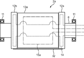
- FIG. 2 is a cross-sectional side view showing a film forming roller 2 a which is a base material transport roller provided in the film forming apparatus 1.
- the film forming apparatus 1 includes an unwinding unit 3, a film base material transporting unit 4, and a winding unit 5.
- the winding unit 3 unwinds the film substrate W that is a film-like substrate from the substrate roll.
- the base material roll is obtained by winding the film base material W into a roll shape.
- the film base W has a width of about 1 meter and a small thickness of about several tens to several hundreds of ⁇ m, for example, and is made of, for example, resin or glass.
- the film base material transport unit 4 transports the unwound film base material W to the surface treatment process. In this surface treatment step, the film substrate W is subjected to a surface treatment by a sputtering method, a CVD method, or the like.
- the said winding part 5 winds up the film base material W in which the surface treatment was given again as a roll-shaped base material roll. That is, the film forming apparatus 1 conveys a long film substrate W of, for example, 100 m or more from the substrate roll of the unwinding unit 3 to the substrate roll of the winding unit 5 by a so-called roll-to-roll method. However, it is an apparatus for performing a surface treatment on the film substrate W.
- the up-down direction toward the paper surface of FIG. 1 is the up-down direction of the film forming apparatus 1, and the left-right direction toward the paper surface is also the left-right direction of the film forming apparatus 1.
- the paper surface penetration direction of FIG. 1 is called the front-back direction.
- the film forming apparatus 1 further includes a vacuum chamber 6.
- the vacuum chamber 6 accommodates the unwinding unit 3, the film base material transport unit 4, and the winding unit 5.
- the vacuum chamber 6 has, for example, a box shape and is formed in a bowl shape with a hollow inside. Further, the vacuum chamber 6 has a function of keeping the inside airtight with respect to the outside of the vacuum chamber 6.
- a vacuum pump (not shown) is provided below the vacuum chamber 6. By this vacuum pump, the inside of the vacuum chamber 6 is depressurized to a low pressure state or a vacuum state.
- the unwinding part 3 is arranged on the upper left side of the central part in the vertical direction in the vacuum chamber 6 shown in FIG.
- the unwinding unit 3 has an unwinding core that is a winding core.
- the unwinding core has, for example, a cylindrical shape or a columnar shape slightly longer than the width of the film base W.
- a base material roll is formed by winding the film base material W around the unwinding core.
- the unwinding unit 3 is configured by attaching the base material roll to the film forming apparatus 1.
- the unwinding portion 3 is disposed in the vacuum chamber 6 so that the rotation center axis given thereto is perpendicular to the paper surface of FIG.
- the film forming apparatus 1 includes a film forming unit.
- the film forming unit is provided at a position below the center in the vertical direction in the vacuum chamber 6 shown in FIG.
- the film forming unit performs a surface treatment (surface treatment step) on the surface of the film substrate W unwound from the unwinding unit 3 by, for example, sputtering or plasma CVD.
- a sputtering film forming unit 7 by a sputtering method is disclosed as an example of the film forming unit.
- the film base material transport unit 4 includes a base material transport roller for transporting the film base material W in the sputtering film forming unit 7 that performs the surface treatment process.
- FIG. 1 shows a film forming roller 2a and a pair of sputter evaporation sources T, which are a part of the configuration of a general sputtering film forming unit and are examples of the substrate transport roller.
- the film forming roller 2a has a cylindrical outer peripheral surface, and conveys the film substrate W wound around the film forming roller 2a.
- the film forming roller 2 a has a rotation shaft 8 and rotates around a rotation center axis that is a center axis of the rotation shaft 8.
- the film forming roller 2 a is arranged so that the rotation center axis is substantially parallel to the rotation center axis of the unwinding unit 3.
- the film forming roller 2a In the film forming roller 2a, temperature control for appropriately raising and lowering the temperature of the substrate in accordance with the sputtering conditions is performed.
- the film forming roller 2a according to the present embodiment has a unique configuration for enabling the temperature control as a feature thereof. The detailed configuration of the film forming roller 2a will be described later.
- the sputter evaporation source T is disposed on each of the left and right sides of the film forming roller 2a so as to face the film substrate W conveyed by the film forming roller 2a.
- the sputter evaporation source T is an evaporation source containing a component to be deposited on the surface of the film substrate W. As is well known, this component is sputtered (evaporated) by glow discharge, guided to the surface of the film substrate W, and deposited on the surface.
- the winding unit 5 is arranged on the right side of the unwinding unit 3 in the vacuum chamber 6 shown in FIG.
- the winding unit 5 winds the film substrate W that has been surface-treated through the film substrate transport unit 4 as a roll-shaped substrate roll, and has the same configuration as the unwinding unit 3. And they are arranged in the same way.
- the film forming apparatus 1 further includes a first guide roller 9 and a second guide roller 10 as shown in FIG.
- the first guide roller 9 is provided near the film forming roller 2a between the unwinding portion 3 and the film forming roller 2a.
- the first guide roller 9 is arranged in the left-right direction of the vacuum chamber 6 closer to the center of the vacuum chamber 6 than the left end of the film-forming roller 2a, that is, closer to the rotation shaft 8 of the film-forming roller 2a.
- the first guide roller 9 is disposed so as to be rotatable about a rotation center axis provided thereto, and the rotation center axis is parallel to the rotation center axes of the unwinding unit 3 and the film forming roller 2a.
- the first guide roller 9 can always convey the substrate W from the film forming roller 2a from a certain angle and direction.
- the second guide roller 10 is disposed on the right side of the first guide roller 9 between the winding unit 5 and the film forming roller 2a.
- the second guide roller 10 has the same configuration as the first guide roller 9 and has an outer diameter that is substantially the same as the outer diameter of the first guide roller 9.
- FIG. 2 is a cross-sectional side view of the film forming roller 2a, and shows the configuration of the film forming roller 2a when viewed from the right or left side of the film forming apparatus 1 shown in FIG.
- the vertical direction toward the paper surface of FIG. 2 matches the vertical direction of the film forming apparatus 1 shown in FIG.
- the rotation center axis of the film forming roller 2a extending in the direction perpendicular to the paper surface (through direction), that is, the center axis of the rotation axis 8 is shown along the left-right direction in FIG.
- the film forming roller 2a includes a pair of bearings 11, a pair of end segments 12a and 12b, a center segment 13a, both end heating / cooling mechanisms, and a center heating / cooling mechanism.
- the bearings 11 are arranged at positions separated from each other in the front-rear direction in the vacuum chamber 6 and hold the end portions of the rotating shaft 8 at the positions so as to be rotatable. That is, the rotating shaft 8 can rotate around its central axis while being held by both bearings 11.
- the both end segments 12 a and 12 b are provided around the rotary shaft 8 at positions spaced apart from each other in the axial direction of the rotary shaft 8, and rotate integrally with the rotary shaft 8.
- the center segment 13a is provided around the rotary shaft 8 at a position sandwiched between the both end segments 12a and 12b.
- the both end temperature increasing / decreasing mechanism has both end temperature increasing / decreasing medium paths 14 which are medium paths indicated by broken lines in FIG. 2, and the both end temperature increasing / decreasing medium paths 14 are provided inside the end segments 12a and 12b.
- the central heating / cooling mechanism has a central heating / cooling medium path 15a which is a medium path indicated by a broken line in FIG. 2, and the central heating / warming medium path 15a is provided inside the central segment 13a. .
- the rotary shaft 8 is a columnar or cylindrical member having a constant outer diameter, and portions near both ends thereof are held by the bearings 11. In this way, the rotation shaft 8 can be rotated around the longitudinal direction, that is, the central axis along the axial direction, that is, the rotation center axis of the film forming roller 2a, and is rotated at a predetermined rotation speed by a driving device (not shown). Driven.
- the end segment 12 a is provided at a position close to the bearing 11 on the right side of the center in the longitudinal direction of the rotary shaft 8, and the end segment 12 b is arranged in the longitudinal direction of the rotary shaft 8. It is provided at a position near the bearing 11 on the left side from the center.
- Both end segments 12a and 12b are disk-shaped and have a predetermined thickness sufficient to wrap the end (side) side in the width direction of the film substrate W.
- Both end segments 12a and 12b each have a cylindrical second outer peripheral surface and a third outer peripheral surface that are coaxial with the rotation center axis of the film forming roller 2a.
- the diameters of the second and third outer peripheral surfaces, that is, the outer diameters of both end segments 12 a and 12 b are arbitrarily determined according to the desired performance of the film forming apparatus 1, but are at least larger than the outer diameter of the rotating shaft 8. large.
- Both end segments 12a and 12b are provided so as to be coaxial with the rotary shaft 8 at a position with a sufficient gap therebetween.
- the spacing is sufficient for both ends (both sides) in the width direction of the film substrate W to be wound around the both end segments 12a and 12b, and has a size smaller than the width of the film substrate W.
- Both end segments 12a and 12b are provided at positions that are substantially symmetrical with respect to the center position in the longitudinal direction of the rotating shaft 8.
- Both end segments 12a and 12b may be formed integrally with the rotary shaft 8, or may be formed as a member different from the rotary shaft 8 and fixed to the rotary shaft 8 using a fixture. In any case, the both end segments 12 a and 12 b can be rotated in accordance with the rotation of the rotary shaft 8.
- FIG. 2 shows a state in which the film base W is wound around the both end segments 12a and 12b.
- the center position in the width direction of the film substrate W substantially coincides with the longitudinal direction of the rotating shaft 8, that is, the center position in the axial direction, and both ends (both sides) in the width direction of the film substrate W are both ends. It exists on the 2nd and 3rd outer peripheral surface of part segment 12a, 12b.
- the film base W wound around the both end segments 12a and 12b is conveyed by the rotation of the both end segments 12a and 12b.
- the center segment 13a has an outer diameter that is smaller than the outer diameter of the end segments 12a, 12b. That is, the central segment 13a has a first outer peripheral surface having a diameter smaller than the diameters of the second and third outer peripheral surfaces of the end segment 12a, 12b.
- the center segment 13a is provided so as to be spaced from the both end segments 12a and 12b inside by a predetermined distance and to be coaxial with the both end segments 12a and 12b and the rotary shaft 8.
- the central segment 13a may be formed integrally with the rotating shaft 8, or may be formed as a member different from the rotating shaft 8 and fixed to the rotating shaft 8 using a fixture. In any case, the central segment 13a can be rotated in accordance with the rotation of the rotary shaft 8.
- the outer diameter of the central segment 13a that is, the diameter of the first outer peripheral surface is smaller than the outer diameters of the end segments 12a, 12b, that is, the diameters of the second and third outer peripheral surfaces.
- the contact between the inner surface of the film base W wound on the second and third outer peripheral surfaces of 12a and 12b and the first outer peripheral surface of the central segment 13a is prevented, and a space between both surfaces is prevented. (Gap) is formed.
- the diameter of the central segment 13a is arbitrarily determined so that a space suitable for the desired performance of the film forming apparatus 1 is formed between the first outer peripheral surface of the central segment 13a and the film substrate W.
- the length along the axial center of the central segment 13a also matches the performance of the film forming apparatus 1 where the distance (gap) between the end segments 12a and 12b and the central segment 13a is desired. It is arbitrarily determined so as to be an interval. Further, it is desirable that the central segment 13a is provided so that two intervals formed between the end segments 12a and 12b on both ends of the central segment 13a are substantially equal to each other. As a result, in the longitudinal direction of the rotating shaft 8, that is, in the axial direction, the center position in the longitudinal direction of the central segment 13a, the intermediate position between the end segments 12a and 12b, and the central position of the rotating shaft 8 are substantially equal. As a result, the film forming roller 2a has a substantially symmetrical outer shape with respect to the center position in the longitudinal direction of the rotating shaft 8.
- the central segment 13a and the end segments 12a and 12b are separated from each other with an interval in the axial direction, and the rotating shaft 8 rotates.
- the central segment 13a and the end segments 12a, 12b that are formed integrally with the rotary shaft 8 or fixed to the rotary shaft 8 rotate in synchronization with each other.
- the both end temperature raising / lowering mechanism has the both end temperature raising / lowering medium path 14 provided in the end segments 12a and 12b as described above, and the both end temperature raising / lowering medium path 14 includes, for example, heat medium oil or water.
- the fluid is circulated as a heating / cooling medium.
- route 14 is comprised by pipes and other tubular members, for example.
- the both end temperature raising / lowering mechanism may be configured by a sheath heater embedded in the end segments 12a and 12b.
- the both end temperature raising / lowering medium path 14 passes the temperature raising / lowering medium from the outside of the film forming roller 2a to the right end segment 12a and further through the rotating shaft 8 to the left end segment 12b. After being introduced into the interior, it is arranged so as to be folded back within the end segment 12b and led out to the outside in the reverse order.
- the both end temperature raising / lowering medium path 14 includes a portion embedded in each of both end segments 12a and 12b, an intermediate portion that relays these portions via the rotary shaft 8, and a right end segment 12a. And a portion connecting the heat medium supply source outside the film forming roller 2a.
- the portions embedded in the end segments 12a and 12b are arranged along the second and third outer peripheral surfaces of the end segments 12a and 12b and facing the substrate W. .
- the heated and cooled heating / cooling medium circulates in the tubular both ends heating / warming medium path 14 arranged in this manner, so that the second and third outer peripheral surfaces of the end segments 12a, 12b, that is, the upper and lower surfaces thereof.
- the temperature of the surface around which the film substrate W is wound increases or decreases, and thereby the temperature of the film substrate W wound around the end segments 12a and 12b increases or decreases.
- a sheath heater having a similar shape is embedded in the end segments 12a and 12b instead of the both end heating and cooling medium paths 14, the end segments 12a and 12b can be obtained by changing the heat generation amount of the sheath heater.
- both end part temperature raising / lowering mechanism changes the temperature of the end segment 12a, 12b by changing the temperature of the 2nd and 3rd outer peripheral surface of the end segment 12a, 12b, ie, the surface around which the film base material W is wound. It is possible to control the temperature of the film substrate W wound around the film.
- the central heating / cooling mechanism has the central heating / cooling medium path 15a provided inside the central segment 13a as described above, and fluid such as heat medium oil or water is supplied to the central heating / cooling medium path 15a. It is circulated as a heating / cooling medium.
- the central heating / cooling medium path 15a is constituted by, for example, a pipe or other tubular member.
- the central temperature raising / lowering mechanism may be configured by a sheath heater embedded in the central segment 13a.
- the central heating / cooling medium path 15a introduces the heating / warming medium from the outside of the film forming roller 2a into the central segment 13a, and the first in the central segment 13a.
- the film is arranged so as to be guided to the outside of the film forming roller 2a. That is, the central heating / cooling medium path 15a has a portion embedded inside the central segment 13a and a portion connecting this portion and a heat medium supply source outside the film forming roller 2a.
- the portion embedded in the center segment 13a is arranged along the surface that is the first outer peripheral surface of the center segment 13a and faces the substrate W.
- the heated or cooled heating / cooling medium circulates in the tubular central heating / cooling medium path 15a arranged in this manner, so that the film base W is the first outer peripheral surface of the central segment 13a.
- the temperature of the surface facing the substrate rises or falls, whereby the temperature of the film substrate W facing the first outer peripheral surface rises or falls.
- a sheath heater having a similar shape is embedded in the central segment 13a instead of the central heating / cooling medium path 15a
- the first segment of the central segment 13a is changed by changing the amount of heat generated by the sheath heater.
- the temperature of the outer peripheral surface of the film and the temperature of the film substrate W facing this can be raised.
- the central temperature raising / lowering mechanism changes the temperature of the first outer peripheral surface of the central segment 13a and faces the film substrate W, so that the film facing the first outer peripheral surface is changed.
- the temperature of the base material W can be controlled.
- the both end temperature raising and lowering mechanism for raising and lowering the temperature of the both end segments 12a and 12b and the center temperature raising and lowering mechanism for raising and lowering the temperature of the center segment 13a operate independently of each other. Therefore, the both end temperature raising / lowering mechanism and the central temperature raising / lowering mechanism have the both end temperature raising / lowering medium path 14 and the center part heating / warming medium path 15a, respectively, and these paths 14, 15a have different temperatures.
- the temperature of the central segment 13a and the end segment 12a are controlled by separately controlling the temperatures of the sheath heaters. , 12b can be controlled independently of each other.
- the temperatures of the central segment 13a and the end segments 12a and 12b that are spaced apart from each other can be controlled independently of each other, the temperature of the central segment 13a is greatly increased or decreased.
- the temperature of the end segments 12a and 12b (temperature control range) is controlled while the temperature of the film substrate W is sufficiently controlled to the required temperature, and the end segments 12a and 12b are thermally expanded and deformed. Can be suppressed to a range that does not cause any problems. For example, maintaining the end segments 12a and 12b in contact with the film substrate W at a low temperature while keeping the center segment 13a at a high temperature in order to raise the temperature of the substrate W to a temperature required for the sputtering process.
- FIG. 3 shows a schematic configuration of the film forming roller 2b of this modification.
- the film forming roller 2b further includes a pair of temperature gradient portions 16 in addition to the components of the film forming roller 2a shown in FIG. Therefore, only the temperature gradient portion 16 will be described below.
- Each temperature gradient portion 16 is made of a heat insulating material, and is preferably made of a heat insulating material having a low thermal conductivity such as ceramic.
- Each temperature gradient part 16 is each arrange
- the temperature gradient portion 16 has, for example, a substantially disk shape having a thickness corresponding to the interval formed between the center segment 13a and the end segments 12a and 12b, and is coaxial with the rotation shaft 8 of the film forming roller 2b. It is provided to become.
- both temperature gradient portions 16 insulate between the central segment 13a and the end segments 12a, 12b while being in close contact with the central segment 13a and the end segments 12a, 12b.
- a sufficient temperature gradient is created between the end segments 12a, 12b. Therefore, even when the temperature change of the central segment 13a is large, the end segments 12a and 12b are not easily affected by the temperature change.
- the film forming roller 2b of this modification a wider temperature control range of the film base W can be ensured.
- the film substrate transport unit of the present embodiment and the above-described modified example is not shown in FIGS. 1 to 3, but in addition to the above-described configuration, the pressure bulkhead and the film substrate W between the film segment W and the central segment 13a. It has a gas introduction mechanism for introducing gas into the formed space (gas introduction space).
- gas introduction space gas introduction space
- the pressure bulkhead is provided at a position facing the surface of the first outer peripheral surface of the central segment 13a that does not face the substrate W.
- the first partition roller 9 shown in FIG. 1 is provided so that the pressure partition covers the surface of the film forming roller (center segment 13a and end segments 12a, 12b) 2a or 2b that does not face the film base W.
- the second guide roller 10 is closed.
- the pressure partition provided in this way is between the film base W and the central segment 13a together with the film base W, the central segment 13a, and the end segments 12a and 12b that are in contact with the end segments 12a and 12b.
- a closed space including a gas introduction space formed in the space is formed. Therefore, when the gas is introduced into the closed space by the gas introduction mechanism, the pressure inside the closed space is sufficiently maintained.
- the problem that the pressure in the gas introduction space does not sufficiently increase in a vacuum environment can be avoided by including the gas introduction space in the closed space. That is, the gas introduction space can be maintained at a predetermined pressure, and the heat transfer efficiency between the film substrate W and the central segment 13a can be improved via the gas in the gas introduction space. .
- the gas introduction mechanism includes, for example, a tubular pipe having a hollow inside, and the pipe has a hole along the longitudinal direction for allowing the gas supplied to the cavity in the pipe to flow out of the pipe. Are formed.
- a pipe-like gas introduction mechanism is disposed along the longitudinal direction of the film forming roller 2a or 2b between the pressure partition and the central segment 13a.
- An introduction gas source is connected to the gas introduction mechanism via a gas supply pipe, and an adjustment valve such as a needle valve is provided in the gas supply pipe. This regulating valve changes the flow rate of the gas supplied to the gas introduction mechanism.
- the gas supplied into the gas introduction space by the gas introduction mechanism is an inert gas that does not adversely affect the film formation by the sputtering method.
- the two-stage substrate having the end segments 12a and 12b that are the large-diameter portions at both ends and the central segment 13a that is the small-diameter portion at the center.
- the pressure in the vacuum chamber is maintained at a vacuum required for sputtering, and the non-contact portion between the base material W and the base material transport roller, that is, the first segment 13a.
- Gas can be supplied to a location between the outer peripheral surface and the substrate W. Therefore, the contribution of heat transfer using gas molecules as a medium in addition to radiant heat can be increased, and the efficiency of heat transfer from the substrate W, whose temperature has risen due to heat entering through the film formation process, to the substrate transport roller is improved. To do.
- FIG. 4A is a cross-sectional side view of the film forming roller 2c of the film forming apparatus 1 according to the second embodiment, and is a view of the film forming roller 2c viewed from the right side or the left side of the film forming apparatus 1.
- FIG. . 4B is a cross-sectional view taken along the line IVB-IVB in FIG. 4A, and shows a cross section of the film forming roller 2c when the film forming roller 2c is viewed along the axial direction. .
- the film forming roller 2c of the present embodiment includes a rotating shaft 8, end segments 12a and 12b, a central segment 13b, an end heating / cooling mechanism, and a center heating / cooling mechanism.
- the rotating shaft 8, the end segments 12a and 12b, and the end heating / cooling mechanism are the same as those of the film forming roller 2a of the first embodiment, but the center segment 13b and the center heating / cooling temperature are the same.
- the mechanism is different from the central segment 13a of the film forming roller 2a of the first embodiment and its central temperature raising / lowering mechanism.
- the structure of the center part segment 13b and the center part temperature raising / lowering mechanism which are the differences will be described.
- the center segment 13b has a cylindrical shape having the same outer shape and outer diameter as the center segment 13a of the first embodiment. That is, it has a cylindrical shape having a first outer peripheral surface.
- the central segment 13b has a cylindrical shape that surrounds the through hole along the axis at the center.
- the through hole has a larger hole diameter than the outer diameter of the rotary shaft 8, and the rotary shaft 8 does not contact the inner peripheral surface of the central segment 13b surrounding the through hole over the entire circumference and substantially. It is inserted inside the central segment 13b so as to be coaxial. That is, it is loosely fitted to the central segment 13b. Therefore, the central segment 13 b is not fixed to the rotating shaft 8.
- the central segment 13b is also spaced apart from the end segments 12a and 12b in the axial direction at a predetermined interval, and is not fixed to the end segments 12a and 12b. Therefore, as the rotation shaft 8 rotates, the end segments 12a and 12b that come into contact with the film substrate W rotate integrally with the rotation shaft 8, but the center segment 13b that does not contact the film substrate W does not rotate. .
- Such a non-rotating central segment 13b has a rotational axis by providing a fixture on the surface of the first outer peripheral surface that does not face the film substrate W wound around the end segments 12a and 12b. 8 is fixed to the vacuum chamber 6 so that the relative position to 8 does not change.
- the central heating / cooling mechanism has a central heating / cooling medium path 15b provided inside the central segment 13b, and a fluid such as heat medium oil or water is used as the heating / cooling medium in the central heating / cooling medium path 15b. It will be circulated.
- the central heating / cooling medium path 15b is constituted by, for example, a pipe or other tubular member.
- the central temperature raising / lowering mechanism may be configured by a sheath heater embedded in the central segment 13b.
- the central heating / cooling medium path 15b has a central segment 13b from the surface of the first outer peripheral surface that does not face the film substrate W.
- the center segment 13b is arranged so as to be guided to the outside of the film forming roller 2c after making a round along the surface of the first outer peripheral surface that faces the film base W. That is, the central heating / cooling medium path 15b is a portion connecting the portion embedded in the central segment 13b and the heat medium supply source outside the film forming roller 2c across the first outer peripheral surface. And having.
- the portion embedded in the center segment 13b is arranged along the first outer peripheral surface of the center segment 13b that faces the substrate W.
- the central heating / cooling medium path 15b in the present embodiment is directly introduced into the central segment 13b without passing through the rotary shaft 8 and the end segments 12a and 12b, as in the first embodiment. It is also led directly to the outside.
- the heated / cooled heating / cooling medium circulates in the tubular central heating / cooling medium path 15b arranged in this manner, so that it is the first outer peripheral surface of the central segment 13b and faces the film substrate W. The temperature of the surface rises or falls, and the temperature of the film substrate W facing the central segment 13b can be raised or lowered.
- the film base is formed on the first outer peripheral surface of the central segment 13b by changing the heat generation amount of the sheath heater.
- the temperature of the surface facing the material W can be increased, and the temperature of the film substrate W facing the center segment 13b can be increased.
- the central heating / cooling medium path 15b in the present embodiment also operates independently without being interlocked with the both-ends heating / cooling mechanism, similarly to the central heating / warming medium path 15a in the first embodiment. Therefore, the both end temperature raising / lowering mechanism and the central temperature raising / lowering mechanism have the both end temperature raising / lowering medium path 14 and the center part heating / warming medium path 15b, respectively. Circulates, or both end temperature raising / lowering mechanisms and the central temperature raising / lowering mechanism have sheath heaters, and the temperature of these sheath heaters is individually controlled, so that the temperature of the central segment 13b and the end segment 12a are controlled. , 12b can be controlled independently of each other.
- the film forming apparatus 1 that performs surface treatment (film forming process) such as sputtering or plasma CVD is exemplified, and the characteristics of the film forming rollers 2a to 2c used in the film forming apparatus 1 are exemplified.
- the film forming rollers 2a to 2c having the configuration described in the present embodiment are limited to the film forming apparatus 1 as long as the temperature of the base material needs to be controlled when the film-like base material is transported. Obviously, it can be applied to various devices.
- the film forming apparatus 1 according to the second embodiment can also include a pressure partition and a gas introduction mechanism similar to those of the first embodiment. These pressure partition walls and the gas introduction mechanism make it possible to maintain the gas introduction space at a predetermined pressure, and improve the heat transfer efficiency between the film substrate W and the central segment 13b via the gas in the gas introduction space. Make it possible to improve.
- FIG. 5A is a cross-sectional side view of the base material transport device 2d of the film forming apparatus 1 according to the third embodiment, that is, a view of the base material transport device 2d viewed from the right or left side of the film forming device 1.
- FIG. 5B is a cross-sectional view taken along the line VB-VB in FIG.
- the base material transport device 2 d includes a film forming roller 17, a pressure partition wall 19, and a gas introduction mechanism 20.
- the film forming roller 17 has substantially the same configuration as that of the film forming roller 2a of the first embodiment, but instead of the center segment 13a and the end segments 12a and 12b according to the first embodiment, a central portion is provided.
- a segment 13c and end segments 12c and 12d are provided.
- both end heating / heating medium paths equivalent to the both end heating / warming medium paths 14 according to the first embodiment are provided.
- the inside of the central segment 13c is divided into a plurality of regions (zones) aligned in the circumferential direction, and the central heating / cooling mechanism of the film forming roller 17 can change the temperature of each zone independently of each other. Provided with a plurality of heating and cooling units.
- the configuration of the central temperature raising / lowering mechanism will be described in detail.
- the central temperature raising / lowering mechanism has a plurality of temperature raising / lowering medium paths 18 as the respective temperature raising / lowering parts.
- a fluid such as heat medium oil or water is circulated as a temperature raising / lowering medium in the temperature raising / lowering medium path 18 and circulated.
- Each heating / warming medium path 18a is constituted by, for example, a pipe or other tubular member.
- the central temperature raising / lowering mechanism may include a plurality of sheath heaters embedded in the central segment 13c.
- each of the heating / cooling medium paths 18 is arranged so as to introduce the heating / cooling medium from the outside of the film forming roller 17 into the central segment 13c.
- the first outer peripheral surface 13c is disposed along the surface facing the substrate W.
- Three regions ZONE1, ZONE2, and ZONE3 are set inside the central segment 13c.
- Each of the heating / warming medium paths 18 is provided in each of the zones ZONE1 to ZONE3 independently of each other. That is, the heating / cooling medium path 18 provided in each of the zones ZONE1 to ZONE3 is formed after making a round along the first outer peripheral surface facing the substrate W in each zone ZONE1 to ZONE3.
- FIG. 17 In the film forming roller 17 in this embodiment, the end segments 12c and 12d rotate, but the central segment 13c does not rotate. That is, the base material W is transported by the rotation of the end segments 12c and 12d without rotating the central segment 13c.
- the heated / cooled heating / cooling medium circulates independently through the plurality of tubular heating / cooling medium paths 18 arranged independently from each other, so that each of the zones ZONE1 to ZONE3 in the central segment 13c has a base.
- the temperature of the surface facing the material W rises or falls independently of each other. Thereby, the temperature of the base material W facing the surface existing in each of the regions ZONE1 to ZONE3 in the first outer peripheral surface of the central segment 13c can be increased or decreased.
- the number of regions set in the central segment 13c is not limited to three. Two regions or four or more regions may be set in the central segment 13c. The number of regions to be set can be arbitrarily selected according to characteristics desired for the substrate transport apparatus 2d.
- the central temperature increasing / decreasing mechanism having the plurality of temperature increasing / decreasing medium paths 18 independently determines the temperature of the surface of the first outer peripheral surface of the central segment 13c facing the substrate W for each region.
- the temperature of the substrate W facing the first outer peripheral surface of the central segment 13c can be adjusted to a temperature corresponding to each of a plurality of film forming processes on the single film forming roller 17. It is to realize that.
- the substrate transport apparatus 2d of the present embodiment since it is not necessary to use a plurality of film forming rollers for each temperature of the film forming process, the capacity of the vacuum chamber can be reduced, and consequently the film forming apparatus 1 Can be miniaturized. Furthermore, if the heat insulation between the zones ZONE1 to ZONE3 can be ensured, the temperature of each zone can be controlled almost accurately and independently. If the number of regions provided in the central segment 13c can be increased by further subdividing the regions, a plurality of processes can be realized on one film forming roller 17, and the film forming apparatus can be further downsized. It becomes possible to do.
- the pressure partition wall 19 is provided at a position facing the surface of the first outer peripheral surface of the central segment 13c that does not face the substrate W.
- the pressure partition wall 19 is a surface of the film forming roller 17 that does not oppose the film substrate W among the first outer peripheral surface of the central segment 13c and the second and third outer peripheral surfaces of the end segments 12c and 12d. It is provided so as to cover and to close the opening between the first guide roller 9 and the second guide roller 10.
- the pressure partition wall 19 thus provided is almost sealed together with the base material W, the central segment 13c, and the end segments 12c, 12d that are in contact with the second and third outer peripheral surfaces of the end segments 12c, 12d.
- a closed space that includes a gas introduction space formed between the film substrate W and the central segment 13c, so that when the gas is introduced by the gas introduction mechanism 20, the closed space is closed. It allows the pressure inside the space to be sufficiently retained.
- the inclusion of the gas introduction space in the almost closed space as described above makes it possible to avoid the problem that the pressure in the gas introduction space does not rise sufficiently in a vacuum environment. That is, the gas introduction space can be maintained at a predetermined pressure, and the heat transfer efficiency between the film substrate W and the central segment 13c can be improved via the gas in the gas introduction space. .
- the pressure partition wall 19 includes a first airtight portion 19 a facing the base material W wound around the first guide roller 9, and a base material W wound around the second guide roller 10. It has a second airtight portion 19b facing each other, a connecting portion 19c that connects the first airtight portion 19a and the second airtight portion 19b to each other, a first wall portion 19d, and a second wall portion 19e.
- the first and second wall portions 19d and 19e are respectively provided on both sides of the pressure partition wall 19 in the left-right direction (the left-right direction in FIG. 5A), and the first air-tight portion 19a, the second air-tight portion 19b, and the connection portion 19c. Cover the sides.
- the first hermetic portion 19 a is a columnar member having substantially the same length as the film forming roller 17 along the longitudinal direction of the first guide roller 9.
- This curved surface has a concave shape corresponding to the curvature of the substrate W wound around the first guide roller 9, and this curved surface is formed from, for example, the substrate W wound around the first guide roller 9. It is arranged at a position separated by a minute distance of about 1 mm.
- the second hermetic portion 19 b has the same configuration and shape as the first hermetic portion 19 a and has a curved surface facing the second guide roller 10.
- the curved surface is arranged at a position separated from the base material W wound around the second guide roller 10 by a minute distance of about 1 mm, for example.
- the connecting portion 19c has a flat plate shape and has approximately the same length as the length along the longitudinal direction of the first airtight portion 19a and the second airtight portion 19b.
- the connecting portion 19c integrally connects the first airtight portion 19a and the second airtight portion 19b arranged as described above along the longitudinal direction of the first airtight portion 19a and the second airtight portion 19b.
- the connection portion 19c covers a surface of the film forming roller 17 that does not oppose the film substrate W among the first outer peripheral surface of the central segment 13c and the second and third outer peripheral surfaces of the end segments 12c and 12d. Thus, the opening between the first guide roller 9 and the second guide roller 10 is closed.
- the first hermetic portion 19a, the second hermetic portion 19b, and the connecting portion 19c are connected together so that the first guide roller 9 and the second guide roller 10 are connected to each other.
- a lid that closes the opening is constructed. Openings are formed in one end side and the other end side of the first hermetic part 19a, the second hermetic part 19b, and the connection part 19c integrated as described above.
- the first wall portion 19d closes the opening on the one end side
- the second wall portion 19e closes the opening on the other end side.
- the first wall portion 19d is a flat plate having substantially the same width as the distance between the first guide roller 9 and the second guide roller 10, and the first airtight portion 19a, the second airtight portion 19b, The opening formed between the connecting portion 19c and the end segments 12c and 12d is closed.
- 19 d of 1st wall parts have a surface which opposes the surface which does not contact the base material W among the 2nd outer peripheral surfaces of one edge part segment 12c. This opposing surface is a curved surface that curves along the outer peripheral surface of the end segment 12c.
- the first wall portion 19d includes a first facing surface facing the substrate W conveyed from the first guide roller 9 to the film forming roller 17, and a substrate conveyed from the film forming roller 17 to the second guide roller 10. And a second facing surface that faces W, and the first and second facing surfaces extend along the conveyance direction of the substrate W. These first and second opposing surfaces extend along the conveyance direction of the substrate W between the first guide roller 9 and the second guide roller 10 and the film forming roller 17. In the first wall portion 19d, the first and second opposing surfaces are separated from the substrate W by a minute distance of about 1 mm, for example, and the curved surface facing the end segment 12c is the second end segment 12c.
- the second wall portion 19e has the same configuration and shape as the first wall portion 19d, and is provided on the other end side of the integrated first airtight portion 19a, second airtight portion 19b, and connection portion 19c. It has been.
- the pressure partition wall 19 forms a space between the pressure partition wall 19 and the film forming roller 17, and the space is formed between the base material W wound around the end segments 12c and 12d and the first segment 13c.
- a continuous space surrounding the entire outer periphery of the central segment 13c of the film forming roller 17 is formed by being continuous with the gas introducing space formed between the outer peripheral surface of the first film forming roller 17 and the outer peripheral surface.
- the pressure partition wall 19 can substantially isolate the space surrounding the entire outer periphery of the central segment 13c from the space inside the vacuum chamber 6 outside the space.
- the mechanism 20 makes it possible to adjust the pressure of the gas introduction space to a pressure different from the pressure in the vacuum chamber 6.
- the gas introduction mechanism 20 has, for example, a member constituted by a tubular pipe having a hollow inside.
- the pipe is formed with a plurality of holes along the longitudinal direction for allowing the gas supplied to the cavity to flow out of the pipe.
- the pipe-shaped member constituting such a gas introduction mechanism 20 is disposed so as to extend along the longitudinal direction of the film forming roller 17 between the pressure partition wall 19 and the central segment 13c.
- an introduction gas source 21 is connected to the gas introduction mechanism 20 via a gas supply pipe.
- An adjustment valve 22 is provided in the gas supply pipe.
- the adjustment valve 22 includes a needle valve and adjusts the flow rate of the gas supplied from the introduction gas source 21 to the gas introduction mechanism 20.
- the gas supplied through the gas introduction mechanism 20 is an inert gas that does not adversely affect the film formation by the sputtering method.
- the gas supplied through the gas introduction mechanism 20 fills the space formed between the pressure partition wall 19 and the film forming roller 17, and the base material W and the central segment 13c wound around the end segments 12c and 12d. Into the gas introduction space formed between the two. As a result, the integral space surrounding the entire outer periphery of the central segment 13c of the film forming roller 17 is filled with the gas, and the pressure of the gas introduction space filled with the gas is reduced with respect to the pressure in the vacuum chamber 6 which has been decompressed. Becomes higher. Due to this pressure difference, gas flows out from a gap of about 1 mm provided between the pressure partition wall 19 and the base material W and the end segments 12c and 12d. The pressure of the gas introduction space filled with gas is determined by the balance with the supply amount of gas.
- the surface pressure (contact pressure) that the substrate W receives from the cylindrical surface of the film forming roller 17 is about 140 Pa.
- the tension of the substrate W changes, the surface pressure changes in proportion to the tension. Therefore, when the gas is introduced (supplied) into the gas introduction space between the substrate W and the central segment 13 c of the film forming roller 17, the surface on which the substrate W receives the pressure in the gas introduction space from the film forming roller 17.
- the flow rate of the supply gas from the introduction gas source 21 is adjusted by the adjustment valve 22 so that the pressure is lower than the pressure, the substrate W and the first outer peripheral surface of the central segment 13c of the film forming roller 17 through the gas introduction mechanism It becomes possible to seal the gas supplied in the gas introduction space between the gas introduction space by the contact pressure of the substrate W.
- the film forming process by the sputtering method is performed under a pressure of the order of 0.1 Pa.
- the mean free path of the inert gas argon (Ar) at 0.1 Pa is about 7 cm.
- the mean free path is sufficiently larger than the size of the gap space of the gas introduction space, and may be regarded as a molecular flow.
- the mean free path is inversely proportional to the pressure, and in the pressure range of 10 to 100 Pa, the mean free path is 0.07 to 0.7 mm, which is equivalent to the size of the gap space. Therefore, this region can be regarded as a region where a transition is made from a molecular flow to a viscous flow.
- the number of gas molecules increases in proportion to the pressure, and the number of gas molecules colliding with the wall surface surrounding the gas introduction space also increases.
- the heat balance due to convection between the wall surfaces is an exchange of energy due to collisions of gas molecules when viewed microscopically, and the amount of heat transferred increases as the number of collisions increases. Therefore, the heat transfer coefficient is proportional to the pressure.
- the diameter of the first guide roller 9 and the second guide roller 10 is 74 mm
- the width of the first guide roller 9 and the second guide roller 10 is 370 mm
- the first guide roller 9 and the second guide roller 10 If the gap with the pressure partition wall 19 is 1 mm, and the holding angle (wrapping angle) of the substrate W in the first guide roller 9 and the second guide roller 10 is 90 degrees, the first guide roller 9 and the second guide roller 10
- the gas outlet gap formed by the gap between the pressure partition wall 19 and the pressure partition wall 19 can be modeled as a rectangular slit having an opening of 1 mm ⁇ width of 370 mm and a depth of 60 mm (1/4 of the circumferential length of 74 mm in diameter).
- the influence of the curvatures of the first guide roller 9 and the second guide roller 10 and the influence of the gap between the side surfaces of the first guide roller 9 and the second guide roller 10 occur, but they are not considered here.
- the conductance in this case is estimated to be about 0.003 [m 3 / s] from the modeled rectangular slit equation, and the pressure in the gas introduction space is 100 Pa and the external pressure in the gas introduction space is 0 Pa.
- the amount of gas leakage from the partition wall 19 can be estimated to be about 180 sccm.
- a high vacuum exhaust pump having a sufficient exhaust capability such as a turbo molecular pump (TMP) as a pump for constantly introducing a gas corresponding to the gas leakage amount through the gas introduction mechanism 20 and exhausting the inside of the vacuum chamber 6.
- TMP turbo molecular pump
- the pressure in the gas introduction space can be increased to about 100 to 1000 times the process pressure at the time of sputtering, and the corresponding heat transfer coefficient (which is proportional to the pressure for molecular flow) We can expect a rise.
- the film forming roller 17 includes both end segments 12c and 12d that are large-diameter portions at both ends and a central segment 13c that is a small-diameter portion at the center.
- the gas in the non-contact portion between the base material W and the base material transport roller is maintained while maintaining the pressure in the vacuum chamber 6 at a vacuum required for sputtering. Can be supplied. Therefore, the contribution of heat transfer using gas molecules as a medium in addition to radiant heat can be increased, and the heat transfer efficiency from the substrate W, whose temperature has risen due to heat penetration by the film forming process, to the film forming roller 17 is improved. To do.
- the heat that has entered the base material W by a film forming process such as sputtering can be sufficiently released, and the occurrence of wrinkles and creases in the base material W transported to the base material transport roller having a two-stage shape is prevented. be able to.
- the temperature change of the end segments 12c and 12d that are in contact with the base material W is suppressed to a small level, so that the end segments 12c and 12d
- the substrate W is brought to a temperature necessary for the film forming process by largely changing the temperature of the central segment 13c while suppressing a change in the outer diameter of the second and third outer peripheral surfaces and a decrease in cylindricity. Can do.
- the substrate transport apparatus capable of suppressing the temperature change of the end segments 12c and 12d can transport a glass substrate with an edge tab or the like as an object of the film forming process.
- the glass substrate with an edge tab has, for example, a glass substrate and protective members called edge tabs attached to both ends along the longitudinal direction, and most of the edge tabs are formed of a heat-sensitive resin or the like. . Since the glass substrate has a higher melting point than the resin film substrate, when the glass substrate is the object of the film formation process, the resin film substrate with low heat resistance is the object of the film formation process.
- the temperature of the end segment in contact with the edge tab having low heat resistance is kept low, and the temperature of the central segment is increased to increase the heat resistant glass. Since the substrate can be heated, it is possible to perform film formation making the best use of the high heat resistance of the glass substrate while suppressing the deformation of the edge tab.
- the film forming apparatus 1 that performs surface treatment (film forming process) such as sputtering or plasma CVD is exemplified, and the characteristics of the substrate transport roller used in the film forming apparatus 1 are described.
- the base material transport roller having the configuration described in each embodiment is not limited to the film forming device 1 as long as it is a device that needs to control the temperature of the base material W when transporting the film-shaped base material W. Obviously, it can be applied to various devices.
- the present invention provides a base material transport roller that makes it possible to control the temperature of a base material over a wide region without deteriorating the transport quality of the base material.
- the base material transport roller is provided in a film forming apparatus for performing a film forming process on the surface of the base material so as to be rotatable around a specific central axis, and transports the base material.
- a central segment provided at a central portion in the axial direction and having a cylindrical first outer peripheral surface coaxial with the central axis, and positioned on both outer sides in the axial direction of the central segment and coaxial with the central axis
- Each of the cylindrical second outer peripheral surface and the third outer peripheral surface, and the second outer peripheral surface and the third outer peripheral surface are formed on the second outer peripheral surface and the third outer peripheral surface, respectively.
- the temperature of the central segment and the temperature of the end segment can be controlled independently of each other. Therefore, for example, while controlling the temperature of the film substrate to the required temperature by greatly increasing or decreasing the temperature of the central segment, the end segment has a temperature control range (temperature control range). It can suppress to the range which does not cause thermal expansion and thermal deformation.
- the center segment and the end segment may be separated from each other or may be rotated in synchronization with each other. In the latter case, it is possible to convey the substrate by rotating the end segment while the central segment is not rotated.
- a temperature gradient portion that generates a temperature gradient between the central segment and the end segment.
- the temperature gradient portion suppresses the influence of the change in the temperature of the central segment on the temperature of the end segment, thereby enabling the accuracy of temperature control of the end segment to be increased.
- the temperature gradient portion for example, one including a heat insulating material provided between the central segment and the end segment to insulate between the segments is suitable.
Landscapes
- Chemical & Material Sciences (AREA)
- Chemical Kinetics & Catalysis (AREA)
- Engineering & Computer Science (AREA)
- Materials Engineering (AREA)
- Mechanical Engineering (AREA)
- Metallurgy (AREA)
- Organic Chemistry (AREA)
- General Chemical & Material Sciences (AREA)
- Physical Vapour Deposition (AREA)
Abstract
Description
図1及び図2を参照しながら、本発明の第1実施形態による成膜装置1について説明する。図1は、本実施形態による成膜装置1の断面正面図である。図2は、前記成膜装置1に設けられる基材搬送ローラである成膜ローラ2aを示す断面側面図である。
図3を参照して、第1実施形態の変形例について説明する。
図4を参照して、本発明の第2実施形態について説明する。図4(a)は、第2実施形態による成膜装置1の成膜ローラ2cの断面側面図であって当該成膜ローラ2cを成膜装置1の右方又は左方から見た図である。図4(b)は、図4(a)におけるIVB-IVB線に沿った断面図であり、成膜ローラ2cを軸心方向に沿って見たときの成膜ローラ2cの断面を示している。
図5を参照して、本発明の第3実施形態について説明する。図5(a)は、第3実施形態による成膜装置1の基材搬送装置2dの断面側面図、つまり、成膜装置1の右方又は左方から基材搬送装置2dを見た図であり、図5(b)は、図5(a)におけるVB-VB線に沿った断面図である。
Claims (5)
- 基材の表面に成膜処理を施す成膜装置に特定の中心軸回りに回転可能に設けられて前記基材を搬送する基材搬送ローラであって、
前記中心軸に沿った軸方向における中央部に設けられ、第1の外周面を有する中央部セグメントと、前記中央部セグメントの軸方向の両外側にそれぞれ位置し、前記中心軸と同軸の円筒状の第2の外周面及び第3の外周面をそれぞれ有し、これらの第2の外周面及び第3の外周面は、当該第2の外周面及び第3の外周面に前記基材が接触した状態で回転することにより当該基材を搬送するとともに、当該基材が前記第1の外周面に接触するのを阻止するように当該第1の外周面の径よりも大きな径を有する、一対の端部セグメントと、
前記中央部セグメントの温度を変化させる中央部昇降温機構と、
前記各端部セグメントの温度を前記中央部セグメントとは独立して変化させる両端部昇降温機構と、を備える、基材搬送ローラ。 - 請求項1に記載の基材搬送ローラであって、前記中央部セグメントと前記端部セグメントが互いに分離している、基材搬送ローラ。
- 請求項1に記載の基材搬送ローラであって、前記中央部セグメントと前記端部セグメントが、互いに同期して回転する、基材搬送ローラ。
- 請求項2に記載の基材搬送ローラであって、前記中央部セグメントが非回転であって前記端部セグメントが回転する、基材搬送ローラ。
- 請求項2に記載の基材搬送ローラであって、前記中央部セグメントと前記端部セグメントとの間に温度勾配を生じさせる温度勾配部をさらに備える、基材搬送ローラ。
Priority Applications (4)
| Application Number | Priority Date | Filing Date | Title |
|---|---|---|---|
| CN201380066932.XA CN104854256B (zh) | 2012-12-21 | 2013-11-25 | 基材输送辊 |
| KR1020177001360A KR20170010092A (ko) | 2012-12-21 | 2013-11-25 | 성막 롤러 |
| DE112013006112.0T DE112013006112T5 (de) | 2012-12-21 | 2013-11-25 | Substrattransportrolle |
| US14/432,601 US9550202B2 (en) | 2012-12-21 | 2013-11-25 | Substrate transport roller |
Applications Claiming Priority (2)
| Application Number | Priority Date | Filing Date | Title |
|---|---|---|---|
| JP2012-279533 | 2012-12-21 | ||
| JP2012279533A JP5868309B2 (ja) | 2012-12-21 | 2012-12-21 | 基材搬送ロール |
Publications (1)
| Publication Number | Publication Date |
|---|---|
| WO2014097545A1 true WO2014097545A1 (ja) | 2014-06-26 |
Family
ID=50977911
Family Applications (1)
| Application Number | Title | Priority Date | Filing Date |
|---|---|---|---|
| PCT/JP2013/006903 Ceased WO2014097545A1 (ja) | 2012-12-21 | 2013-11-25 | 基材搬送ローラ |
Country Status (7)
| Country | Link |
|---|---|
| US (1) | US9550202B2 (ja) |
| JP (1) | JP5868309B2 (ja) |
| KR (2) | KR20150085040A (ja) |
| CN (1) | CN104854256B (ja) |
| DE (1) | DE112013006112T5 (ja) |
| TW (1) | TWI510663B (ja) |
| WO (1) | WO2014097545A1 (ja) |
Families Citing this family (10)
| Publication number | Priority date | Publication date | Assignee | Title |
|---|---|---|---|---|
| JP6319116B2 (ja) * | 2015-01-23 | 2018-05-09 | 住友金属鉱山株式会社 | 長尺基板の表面処理装置と表面処理方法 |
| DE102016112869B4 (de) * | 2016-07-13 | 2023-03-16 | VON ARDENNE Asset GmbH & Co. KG | Transportanordnung und Prozessieranordnung sowie Verfahren zum Betreiben dieser |
| DE102016112868A1 (de) * | 2016-07-13 | 2018-01-18 | Von Ardenne Gmbh | Transportanordnung und Prozessieranordnung sowie Verfahren |
| US10308461B2 (en) | 2016-11-25 | 2019-06-04 | Industrial Technology Research Institute | Roller assembly and method for transporting a substrate using the same |
| JP6801887B2 (ja) * | 2018-10-18 | 2020-12-16 | 株式会社クリエイティブコーティングス | 成膜装置 |
| JP7381238B2 (ja) * | 2019-07-29 | 2023-11-15 | 日東電工株式会社 | ガラス基材の搬送装置、積層ガラスの製造装置および製造方法 |
| EP4162094A4 (en) * | 2020-06-04 | 2024-10-02 | Applied Materials, Inc. | Vapor deposition apparatus and method for coating a substrate in a vacuum chamber |
| US12060634B2 (en) * | 2021-05-11 | 2024-08-13 | Applied Materials, Inc. | Roller for transporting a flexible substrate, vacuum processing apparatus, and method of cooling a roller |
| CN115413587B (zh) * | 2022-09-14 | 2023-03-24 | 杭州德行至清科技有限公司 | 一种用于动物运输的物理降温方法 |
| CN116219388A (zh) * | 2022-12-31 | 2023-06-06 | 铜陵市超越电子股份有限公司 | 一种双面镀膜的镀膜机 |
Citations (7)
| Publication number | Priority date | Publication date | Assignee | Title |
|---|---|---|---|---|
| JPS58218046A (ja) * | 1982-06-11 | 1983-12-19 | Hitachi Condenser Co Ltd | 磁気記録媒体の製造装置 |
| JP2004143520A (ja) * | 2002-10-24 | 2004-05-20 | Sony Corp | 成膜装置 |
| WO2009060597A1 (ja) * | 2007-11-06 | 2009-05-14 | Panasonic Corporation | 薄膜形成装置及び薄膜の形成方法 |
| JP2009256709A (ja) * | 2008-04-15 | 2009-11-05 | Konica Minolta Holdings Inc | ガイドロール機構、とこれを用いる真空成膜装置、及び有機エレクトロルミネッセンス素子の製造方法 |
| JP2010242200A (ja) * | 2009-04-09 | 2010-10-28 | Toyota Motor Corp | 薄膜部材の製造装置およびその製造方法 |
| JP2011038162A (ja) * | 2009-08-13 | 2011-02-24 | Fuji Electric Holdings Co Ltd | 薄膜積層体の製造装置 |
| WO2012172722A1 (ja) * | 2011-06-15 | 2012-12-20 | パナソニック株式会社 | 基板搬送ローラ、薄膜製造装置及び薄膜製造方法 |
Family Cites Families (7)
| Publication number | Priority date | Publication date | Assignee | Title |
|---|---|---|---|---|
| US3829373A (en) | 1973-01-12 | 1974-08-13 | Coulter Information Systems | Thin film deposition apparatus using segmented target means |
| DE502004002296D1 (de) | 2004-05-22 | 2007-01-25 | Applied Materials Gmbh & Co Kg | Beschichtungsanlage mit einer Messvorrichtung für die Messung von optischen Eigenschaften von beschichteten Substraten |
| WO2008139834A1 (ja) | 2007-05-14 | 2008-11-20 | Ulvac, Inc. | フィルム搬送装置および巻取式真空成膜方法 |
| JP4369531B2 (ja) | 2008-02-20 | 2009-11-25 | パナソニック株式会社 | 薄膜形成装置および薄膜形成方法 |
| US20110076421A1 (en) * | 2009-09-30 | 2011-03-31 | Synos Technology, Inc. | Vapor deposition reactor for forming thin film on curved surface |
| JP4786772B2 (ja) | 2010-01-26 | 2011-10-05 | パナソニック株式会社 | 薄膜の製造装置、薄膜の製造方法及び基板搬送ローラ |
| JP5588375B2 (ja) | 2011-02-18 | 2014-09-10 | カヤバ工業株式会社 | 懸架装置 |
-
2012
- 2012-12-21 JP JP2012279533A patent/JP5868309B2/ja not_active Expired - Fee Related
-
2013
- 2013-11-25 WO PCT/JP2013/006903 patent/WO2014097545A1/ja not_active Ceased
- 2013-11-25 KR KR1020157015797A patent/KR20150085040A/ko not_active Ceased
- 2013-11-25 DE DE112013006112.0T patent/DE112013006112T5/de not_active Ceased
- 2013-11-25 KR KR1020177001360A patent/KR20170010092A/ko not_active Ceased
- 2013-11-25 US US14/432,601 patent/US9550202B2/en not_active Expired - Fee Related
- 2013-11-25 CN CN201380066932.XA patent/CN104854256B/zh not_active Expired - Fee Related
- 2013-12-10 TW TW102145358A patent/TWI510663B/zh not_active IP Right Cessation
Patent Citations (7)
| Publication number | Priority date | Publication date | Assignee | Title |
|---|---|---|---|---|
| JPS58218046A (ja) * | 1982-06-11 | 1983-12-19 | Hitachi Condenser Co Ltd | 磁気記録媒体の製造装置 |
| JP2004143520A (ja) * | 2002-10-24 | 2004-05-20 | Sony Corp | 成膜装置 |
| WO2009060597A1 (ja) * | 2007-11-06 | 2009-05-14 | Panasonic Corporation | 薄膜形成装置及び薄膜の形成方法 |
| JP2009256709A (ja) * | 2008-04-15 | 2009-11-05 | Konica Minolta Holdings Inc | ガイドロール機構、とこれを用いる真空成膜装置、及び有機エレクトロルミネッセンス素子の製造方法 |
| JP2010242200A (ja) * | 2009-04-09 | 2010-10-28 | Toyota Motor Corp | 薄膜部材の製造装置およびその製造方法 |
| JP2011038162A (ja) * | 2009-08-13 | 2011-02-24 | Fuji Electric Holdings Co Ltd | 薄膜積層体の製造装置 |
| WO2012172722A1 (ja) * | 2011-06-15 | 2012-12-20 | パナソニック株式会社 | 基板搬送ローラ、薄膜製造装置及び薄膜製造方法 |
Also Published As
| Publication number | Publication date |
|---|---|
| JP2014122395A (ja) | 2014-07-03 |
| US9550202B2 (en) | 2017-01-24 |
| TW201429839A (zh) | 2014-08-01 |
| CN104854256B (zh) | 2017-05-10 |
| US20150238995A1 (en) | 2015-08-27 |
| DE112013006112T5 (de) | 2015-09-17 |
| KR20170010092A (ko) | 2017-01-25 |
| JP5868309B2 (ja) | 2016-02-24 |
| TWI510663B (zh) | 2015-12-01 |
| CN104854256A (zh) | 2015-08-19 |
| KR20150085040A (ko) | 2015-07-22 |
Similar Documents
| Publication | Publication Date | Title |
|---|---|---|
| JP5868309B2 (ja) | 基材搬送ロール | |
| US20160340776A1 (en) | Roller for spreading of a flexible substrate, apparatus for processing a flexible substrate and method of operating thereof | |
| JP5895179B2 (ja) | 基板搬送ローラ、薄膜製造装置及び薄膜製造方法 | |
| KR102033673B1 (ko) | 조정가능한 전극을 갖는 증착 소스 | |
| JP2020125544A (ja) | 基板上に被膜を被覆する装置及び堆積装置の2つの堆積源間にガス分離を提供する方法 | |
| TWI620828B (zh) | 沉積設備及方法 | |
| WO2011093073A1 (ja) | 薄膜の製造装置、薄膜の製造方法及び基板搬送ローラ | |
| JP5946402B2 (ja) | 基材搬送装置 | |
| EP3495534B1 (en) | Long substrate treatment apparatus and treatment method | |
| CN104955751B (zh) | 幅材引导控制单元、幅材处理设备及其操作方法 | |
| JP6069979B2 (ja) | ガス放出機構付きキャンロール及びこれを搭載した長尺基板の処理装置並びにこれを用いた長尺基板の処理方法 | |
| JP5009845B2 (ja) | 成膜装置 | |
| CN104294223B (zh) | 溅射装置 | |
| JP6408949B2 (ja) | 成膜装置 | |
| JP6183284B2 (ja) | ガス放出機構を備えたキャンロールを用いた長尺フィルムの処理方法 | |
| TW201920728A (zh) | 用以在一真空腔室中使用之熱處理設備、用以沈積材料於一軟質基材上之沈積設備、在一真空腔室中熱處理一軟質基材之方法、及處理一軟質基材之方法 | |
| JP6252402B2 (ja) | 加熱ロールおよびそれを備えた成膜装置 | |
| JP6206374B2 (ja) | 長尺フィルムの円筒型支持体及びこれを備えた長尺フィルムの処理装置 | |
| JP6689642B2 (ja) | 薄膜形成装置 | |
| JP6456439B2 (ja) | スパッタ装置 |
Legal Events
| Date | Code | Title | Description |
|---|---|---|---|
| 121 | Ep: the epo has been informed by wipo that ep was designated in this application |
Ref document number: 13864412 Country of ref document: EP Kind code of ref document: A1 |
|
| WWE | Wipo information: entry into national phase |
Ref document number: 14432601 Country of ref document: US |
|
| ENP | Entry into the national phase |
Ref document number: 20157015797 Country of ref document: KR Kind code of ref document: A |
|
| WWE | Wipo information: entry into national phase |
Ref document number: 1120130061120 Country of ref document: DE Ref document number: 112013006112 Country of ref document: DE |
|
| 122 | Ep: pct application non-entry in european phase |
Ref document number: 13864412 Country of ref document: EP Kind code of ref document: A1 |