WO2014091668A1 - ウインドウモジュール - Google Patents
ウインドウモジュール Download PDFInfo
- Publication number
- WO2014091668A1 WO2014091668A1 PCT/JP2013/006543 JP2013006543W WO2014091668A1 WO 2014091668 A1 WO2014091668 A1 WO 2014091668A1 JP 2013006543 W JP2013006543 W JP 2013006543W WO 2014091668 A1 WO2014091668 A1 WO 2014091668A1
- Authority
- WO
- WIPO (PCT)
- Prior art keywords
- edge
- window
- window panel
- base
- easily deformable
- Prior art date
- Legal status (The legal status is an assumption and is not a legal conclusion. Google has not performed a legal analysis and makes no representation as to the accuracy of the status listed.)
- Ceased
Links
Images






Classifications
-
- B—PERFORMING OPERATIONS; TRANSPORTING
- B60—VEHICLES IN GENERAL
- B60J—WINDOWS, WINDSCREENS, NON-FIXED ROOFS, DOORS, OR SIMILAR DEVICES FOR VEHICLES; REMOVABLE EXTERNAL PROTECTIVE COVERINGS SPECIALLY ADAPTED FOR VEHICLES
- B60J10/00—Sealing arrangements
- B60J10/80—Sealing arrangements specially adapted for opening panels, e.g. doors
- B60J10/82—Sealing arrangements specially adapted for opening panels, e.g. doors for movable panels in roofs
-
- B—PERFORMING OPERATIONS; TRANSPORTING
- B60—VEHICLES IN GENERAL
- B60J—WINDOWS, WINDSCREENS, NON-FIXED ROOFS, DOORS, OR SIMILAR DEVICES FOR VEHICLES; REMOVABLE EXTERNAL PROTECTIVE COVERINGS SPECIALLY ADAPTED FOR VEHICLES
- B60J10/00—Sealing arrangements
- B60J10/20—Sealing arrangements characterised by the shape
- B60J10/22—Sealing arrangements characterised by the shape having varying cross-section in the longitudinal direction
-
- B—PERFORMING OPERATIONS; TRANSPORTING
- B60—VEHICLES IN GENERAL
- B60J—WINDOWS, WINDSCREENS, NON-FIXED ROOFS, DOORS, OR SIMILAR DEVICES FOR VEHICLES; REMOVABLE EXTERNAL PROTECTIVE COVERINGS SPECIALLY ADAPTED FOR VEHICLES
- B60J10/00—Sealing arrangements
- B60J10/20—Sealing arrangements characterised by the shape
- B60J10/24—Sealing arrangements characterised by the shape having tubular parts
-
- B—PERFORMING OPERATIONS; TRANSPORTING
- B60—VEHICLES IN GENERAL
- B60J—WINDOWS, WINDSCREENS, NON-FIXED ROOFS, DOORS, OR SIMILAR DEVICES FOR VEHICLES; REMOVABLE EXTERNAL PROTECTIVE COVERINGS SPECIALLY ADAPTED FOR VEHICLES
- B60J10/00—Sealing arrangements
- B60J10/30—Sealing arrangements characterised by the fastening means
-
- B—PERFORMING OPERATIONS; TRANSPORTING
- B60—VEHICLES IN GENERAL
- B60J—WINDOWS, WINDSCREENS, NON-FIXED ROOFS, DOORS, OR SIMILAR DEVICES FOR VEHICLES; REMOVABLE EXTERNAL PROTECTIVE COVERINGS SPECIALLY ADAPTED FOR VEHICLES
- B60J10/00—Sealing arrangements
- B60J10/70—Sealing arrangements specially adapted for windows or windscreens
- B60J10/74—Sealing arrangements specially adapted for windows or windscreens for sliding window panes, e.g. sash guides
-
- B—PERFORMING OPERATIONS; TRANSPORTING
- B60—VEHICLES IN GENERAL
- B60J—WINDOWS, WINDSCREENS, NON-FIXED ROOFS, DOORS, OR SIMILAR DEVICES FOR VEHICLES; REMOVABLE EXTERNAL PROTECTIVE COVERINGS SPECIALLY ADAPTED FOR VEHICLES
- B60J7/00—Non-fixed roofs; Roofs with movable panels, e.g. rotary sunroofs
- B60J7/02—Non-fixed roofs; Roofs with movable panels, e.g. rotary sunroofs of sliding type, e.g. comprising guide shoes
- B60J7/04—Non-fixed roofs; Roofs with movable panels, e.g. rotary sunroofs of sliding type, e.g. comprising guide shoes with rigid plate-like element or elements, e.g. open roofs with harmonica-type folding rigid panels
- B60J7/043—Sunroofs e.g. sliding above the roof
Definitions
- the present invention relates to a window module provided in an opening of a vehicle or the like.
- a window module such as a sunroof opening formed in a car body is closed by a window module.
- the window module has a window panel made of plate glass or a resin plate, and a resin molding bonded to the edge of the window panel.
- the molding is made of a thermoplastic resin, is molded at the edge of the window panel, and is bonded to the edge. The molding seals the gap between the window panel and the window opening by elastic contact with the edge of the window opening.
- a window module that opens and closes the sunroof opening a molding is formed on the edge of the window panel, a locking groove extending in the longitudinal direction is formed in the molding, and a hollow weather strip with a locking part on the side is prepared.
- Patent Document 1 there is one in which a weather strip is arranged along a molding by engagement between a locking portion and a locking groove (for example, Patent Document 1).
- the window module according to Patent Document 1 does not require the use of an adhesive in order to attach a weather strip excellent in flexibility to the edge of the window panel.
- ⁇ Mole molded along the edge of the window panel shrinks as the temperature drops after molding.
- the window panel does not contract in the molding, the amount of contraction decreases in a portion close to the window panel, while the amount of contraction increases in a portion separated from the window panel. Therefore, a tensile stress is generated by pulling a portion of the molding away from the window panel to a portion close to the window panel.
- deformation disortion
- the shape of the molding and the locking groove changes from the planned shape.
- rattling occurs between the locking groove and the locking portion of the weather strip, and the holding force of the weather strip is reduced.
- the resultant force of the tensile stress generated in the longitudinal direction of the molding faces the curved center side of the molding, and the amount of deformation in that direction increases.
- a molding die is created by predicting the deformation amount after molding of the molding so that the molding has an appropriate shape in a state where the deformation has occurred.
- the present invention has been made in view of the above background, and an object of the present invention is to suppress deformation due to shrinkage after molding in a window module having a molding molded at the edge of a window panel.
- the present invention provides a window module (5) having a window panel (7) and a molding (10) formed at an edge (8) of the window panel and coupled to the edge. And the molding extends along the edge, and a base (15) coupled to the edge, and a protrusion extending from the base and extending along the base ( 16), and the protrusion has an easily deformable portion (41) that is easily deformable in the longitudinal direction as compared with other portions in at least a portion in the longitudinal direction along the edge portion. To do.
- the edge part of a window panel here is a part which forms the outline of a window panel when it sees from the direction which opposes the main surface of a window panel, and a linearly extending part, a corner part (corner part), a curve However, it includes a portion extending while being formed in an annular shape.
- the molding is provided on at least a part of the edge of the window panel.
- the molding may be provided only on the linear part or only on the corner.
- the molding is provided on the entire area of the edge and is annular. It may be.
- the longitudinal direction along the edge of the window panel refers to a direction along a linearly extending portion, a corner portion, a curved extending portion, or the like.
- the said invention further has the weather strip (11) provided with the latching
- the locking groove can maintain a predetermined shape. Accordingly, the locking groove can appropriately hold the locking portion of the weather strip.
- the said edge part of the said window panel has the corner
- the linearly extending portion of the edge of the window panel is defined as a straight portion
- tensile stress is applied to the protruding portion in the direction along the longitudinal direction due to shrinkage after molding.
- the protrusion corresponding to the straight portion has a tensile stress direction in the inside-outside direction of the window panel. Since they are orthogonal, the deformation amount in the inner-outer direction of the window panel is relatively small.
- the tensile stress applied in the longitudinal direction of the protruding portion causes the protruding portion to deform toward the center of the curve (inside the window panel) as a resultant force.
- the amount of deformation of the protruding portion at the corner portion is relatively large.
- the easily deformable portion relaxes the tensile stress at both ends of the corner portion, and reduces the tensile stress of the protruding portion disposed at the corner portion, so that the protruding portion is maintained in a predetermined shape.
- a locking hole (95) is provided in the one side of the said base part (92) and the said protrusion part (93) along the longitudinal direction, and the other side of the said base part and the said protrusion part is provided.
- the projecting portion whose tensile stress is reduced by the easily deformable portion can maintain a cylindrical shape of a predetermined shape.
- the easily deformable portion is formed on the proximal end portion (97) of the protruding portion when viewed from the front surface side of the window panel in a state where the locking piece is locked in the locking hole. It is arranged at the tip side part (99) to be concealed.
- the easily deformable portion is characterized in that the thickness is thinner than other portions of the protruding portion.
- the easily deformable portion has a bellows structure.
- the easily deformable part has a slit.
- the easily deformable portion can be easily expanded and contracted with respect to the longitudinal direction of the molding.
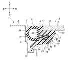
- FIG. 2 is a cross-sectional view taken along the line II-II in FIG. 1 and showing an edge of the window module
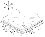
- FIG. 3 A perspective view showing a window panel and a molding without a weather strip.
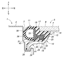
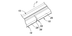
- IV-IV sectional view in Fig. 3 VV cross section in Fig. 3 Sectional view showing a partially modified embodiment of the molding
- Perspective view showing a modified embodiment of the molding The perspective view which shows the front part structure of the vehicle by which the window module which concerns on 2nd Embodiment was provided in the triangular window opening
- FIG. 10 is a cross-sectional view taken along the line IX-IX in FIG. 9 and shows an edge of the window module.
- Perspective view showing form after molding The perspective view which shows the form before the assembly of a mall
- each direction is determined based on the traveling direction of the vehicle.
- FIG. 1 is a perspective view showing an upper structure of a vehicle in which a window module according to the first embodiment is provided in a sunroof opening.
- the roof 2 of the vehicle body 1 is formed with a substantially rectangular sunroof opening 3 that communicates the outside of the vehicle with the inside of the vehicle (vehicle interior).
- the sunroof opening 3 is closed by the window module 5 so as to be opened and closed.
- An opening / closing mechanism (not shown) is provided at the edge 8 of the sunroof opening 3, and the window module 5 is supported by the opening / closing mechanism.
- the opening / closing mechanism includes, for example, a guide rail provided along the front and rear sides of the left and right edges of the sunroof opening 3, a slider that is slidably supported by the guide rail, a window module 5, and a slider that serves as the guide rail. And an actuator to be moved.
- the window module 5 is moved by an opening / closing mechanism between, for example, a closed position where the window module 5 is fitted in the sunroof opening 3 and an open position located on the vehicle exterior side and the rear side with respect to the sunroof opening 3.
- FIG. 2 is a cross-sectional view taken along the line II-II in FIG. 1 and showing the edge of the window module.
- the window module 5 includes a window panel 7, a molding 10 coupled to the edge 8 of the window panel 7, and a weather strip 11 supported by the molding 10.
- the window panel 7 is a substantially rectangular plate member made of glass, resin, or the like.
- FIG. 3 is a perspective view showing a window panel and a molding without a weather strip. As shown in FIG. 3, the corner 13 formed on the rectangular edge 8 of the window panel 7 is curved in an arc shape so as to smoothly connect adjacent side edges.
- the window panel 7 is fixed to the slider of the opening / closing mechanism by a resin fastener (clip), an adhesive, or the like.
- the mall 10 is provided along the edge 8 of the window panel 7 and forms a frame.
- the molding 10 is formed integrally with the window panel 7 by outsert-molding a thermoplastic resin on the edge 8 of the window panel 7.
- An adhesive (primer, not shown) is interposed at the interface between the molding 10 and the window panel 7 in order to improve adhesiveness.
- the molding 10 may be, for example, a polystyrene-based elastomer (TPS), a polyolefin-based elastomer (TPO), a polyvinyl-based elastomer (PVC), or the like.
- the adhesive is not particularly limited as long as it can satisfactorily bond the window panel 7 and the molding 10. For example, when the window panel 7 is a plate glass and the molding 10 is a polystyrene-based elastomer, an olefin-based adhesive is used. An adhesive can be used.
- the molding 10 has a base 15 bonded to the edge 8 of the window panel 7 and a protruding portion 16 protruding from the base 15.
- the base portion 15 extends in the thickness direction (up and down) of the window panel 7 and covers the entire area of the end surface 17 of the window panel 7, and the lower surface 19 of the edge 8 from the lower end of the base portion upper portion 18 (back surface, vehicle interior side surface) ) And a base lower portion 21 extending along the cross section.
- the base 15 is coupled to the window panel 7 at both the base upper portion 18 and the base lower portion 21.
- the upper end surface (vehicle outer end surface) of the base upper portion 18 is formed on the same surface (flash surface) as the upper surface (surface, vehicle outer surface) of the window panel 7.
- the base upper portion 18 and the base lower portion 21 extend along the edge portion 8 of the window panel 7 and have a closed ring shape.
- the direction parallel to the plate surface of the window panel 7 and toward the center of the window panel 7 is the inward direction (right side in FIG. 2) of the window panel 7, and the opposite direction is the outward direction of the window panel 7. (Left side in FIG. 2).
- the protrusion 16 protrudes downward from the inner end portion of the base lower portion 21 and inclines toward the outside of the window panel 7, and then bends and extends outward of the window panel 7. It has a garter portion 26 extending from the tip portion to the outside of the window panel 7 and downward.
- the hook portion 25 forms a locking groove 27 that opens toward the outside of the window panel 7 between the hook portion 25 and the base lower portion 21.
- An upper locking projection 28 that protrudes downward is formed at the outer end of the base lower portion 21, and a lower engagement that protrudes upward so as to face the upper locking projection 28 at the tip of the hook portion 25.
- a stop convex portion 29 is formed.
- the upper locking projection 28 and the lower locking projection 29 narrow the width in the vertical direction of the opening end of the locking groove 27.
- the lower locking projection 29 has a smaller length in the left-right direction (inside and outside of the window panel 7) than the upper locking projection 28.
- the locking groove 27, the upper locking projection 28, and the lower locking projection 29 extend along the longitudinal direction of the molding 10, and the locking groove 27 is an annular groove.
- the weather strip 11 has a cylindrical seal portion 31 and a locking portion 32 protruding from the seal portion 31.
- the locking portion 32 has an enlarged head 33 at the tip, and enters the locking groove 27 and is locked to the upper locking projection 28 and the lower locking projection 29.
- the locking groove 27 is formed so that the length in the vertical direction is smaller than the length in the vertical direction of the locking portion 32 in order to support the locking portion 32 without rattling. It is preferable to clamp the stop 32 from above and below.
- the seal portion 31 and the locking portion 32 are formed in an annular shape so as to extend along the edge portion 8 of the window panel 7.
- the seal base 35 and the locking portion 32 that are portions where the locking portion 32 of the seal portion 31 is provided, and the seal tip portion 36 that is other than the seal base 35 of the seal portion 31 are formed from different resins.
- the seal tip portion 36 is made of a soft rubber material or resin that is more flexible than the seal base portion 35, and the seal base portion 35 and the locking portion 32 are rubber materials or resins that are less flexible than the seal tip portion 36. Is the material.
- the seal tip portion 36, the seal base portion 35, and the locking portion 32 are integrally formed by, for example, two-color molding.
- the seal portion 31 has an outer surface that is flush with the upper end surface of the base upper portion 18 (flash surface). When the window module 5 is in the closed position, the seal portion 31 elastically contacts the edge wall 38 of the sunroof opening 3 and seals between the window module 5 and the sunroof opening 3.
- the garter part 26 is disposed above the water collecting groove 39 formed at the edge 8 of the sunroof opening 3 and collects rainwater that has passed between the seal part 31 of the weather strip 11 and the edge wall 38 of the sunroof opening 3. Guide to water groove 39.
- an easily deformable portion 41 is provided at an appropriate position in the longitudinal direction of the protruding portion 16 along the edge portion 8.
- the easily deformable portion 41 includes a start end portion 42 at which the corner portion 13 of the window panel 7 begins to bend and an end portion 43 at which the end of the bend, that is, a position including the R stop portions disposed at both ends of the corner portion 13.
- the easily deformable portion 41 may be arranged such that one of both ends in the longitudinal direction corresponds to the start end portion 42 or the end portion 43, and is arranged so as to straddle the start end portion 42 or the end portion 43 in the longitudinal direction. Also good.
- the easily deformable portion 41 is a thin portion 45 that extends from the leading edge of the garter portion 26 to the intermediate portion of the hook portion 25.
- the thin-walled portion 45 is formed by providing a concave groove 46 extending from the leading edge of the garter portion 26 on the inner side surfaces of the garter portion 26 and the hook portion 25.
- the thin portion 45 has a curved shape that bulges outward from the window panel 7 with respect to the adjacent garter portions 26.
- the concave groove 46 may be formed on the vehicle outer side surface of the garter portion 26 and the hook portion 25, and the thin portion 45 may have a curved shape bulging inward of the window panel 7. .
- the side wall of the recessed groove 46 may extend in parallel with the thickness direction of the garter part 26 and the hook part 25, or may be inclined with respect to the thickness direction so that the thin part 45 and the surfaces of the garter part 26 and the hook part 25 are formed. It may be continuous with a smooth curved surface.
- the thin portion 45 may be formed over the entire region in the protruding direction of the hook portion 25.
- the thin portion 45 is preferably 1.0 mm, for example, when the thickness of the garter portion 26 is 2.0 to 3.0 mm.
- the thin portion 45 preferably has a width of about 10 mm in the longitudinal direction of the molding 10.
- the thin portion 45 is thinner than the other garter portions 26 and the hook portions 25 and has a curved shape, the thin portion 45 is easier to expand and contract (deform) than the garter portions 26 and the hook portions 25 in the longitudinal direction of the molding 10. It has become.
- the molding 10 is molded and joined at the edge 8 of the window panel 7. Therefore, the molding 10 contracts as the temperature decreases after molding.
- the base 15 is coupled to the window module 5 that does not contract, the amount of contraction is small, and the protruding portion 16 that is separated from the window module 5 contracts more than the base 15. Further, the contraction amount of the protrusion 16 increases as the distance from the base 15 increases. Since the molding 10 extends along the edge 8, the protrusion 16 has a large amount of contraction in the longitudinal direction of the molding 10.
- the protrusion 16 is integrated with the base 15 that does not contract, it is pulled by the base 15. Thereby, a tensile stress is generated in the protruding portion 16.
- the protruding portion 16 extends in the longitudinal direction in the thin portion 45 of the easily deformable portion 41, thereby reducing the tensile stress applied to the other garter portion 26 and the hook portion 25. Thereby, the protrusion part 16 except the easily deformable part 41 does not easily deform due to the tensile stress, and the shape of the locking groove 27 is maintained in a predetermined shape.
- the window module 5 Since the window module 5 according to the first embodiment has the easily deformable portion 41 in the portion corresponding to the curved start end portion 42 and the end end portion 43 of the corner portion 13 of the window panel 7, the protruding portion disposed in the corner portion 13. It becomes difficult to apply a tensile stress to 16, and deformation is suppressed. If the easily deformable portion 41 does not exist, the tensile force applied in the longitudinal direction of the protruding portion 16 acts on the protruding portion 16 curved in the corner portion 13 as a force toward the center of the bending, and the garter portion 26 is The projecting portion 16 to be included is deformed toward the center side of the curve.
- the protrusion part 16 is linear along the side edge of the window panel 7.
- the protrusion 16 may be provided at a curved portion corresponding to the corner portion 13.
- the number of the easily deformable parts 41 can be selected as appropriate.
- the easily deformable portion according to the first embodiment not only relieves stress due to shrinkage after molding, but also relieves stress generated in the mall due to fluctuations in outside air temperature. Further, the easily deformable portion blocks the stress generated in a part of the molding by mechanical contact or the like from being transmitted to the other part.
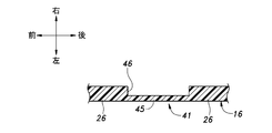
- FIG. 6 is a sectional view showing a partially modified embodiment of the mall.
- the shape of the thin portion 45 may be changed from a curved shape to a linear shape.
- the cross-sectional position of the thin portion 45 shown in FIG. 6 corresponds to the cross section of FIG.
- the thin portion 45 is thin with respect to the other portions of the protruding portion 26, so that the thin portion 45 can easily expand and contract (deform) in the longitudinal direction of the protruding portion 26.
- the easily deformable portion 51 has a bellows structure 52 that can be easily expanded and contracted in the longitudinal direction of the protruding portion 16.
- the bellows structure 52 has a plate shape whose cross section is bent in a zigzag shape or a wave shape in the longitudinal direction of the protruding portion 16.
- the thickness of the member constituting the bellows structure 52 is preferably thinner than the thickness of the other garter part 26 and the hook part 25.
- the bellows structure 52 expands according to the tensile stress generated in the protruding portion 16, reduces the tensile stress applied to the protruding portions 16 other than the easily deformable portion 51, and suppresses deformation.
- the easily deformable portion 55 has a slit 56 that is cut from the protruding end of the garter portion 26 to the intermediate portion in the protruding direction of the hook portion 25.
- the slit 56 is expanded in the longitudinal direction of the protruding portion 16.
- FIG. 9 is a perspective view showing a front structure of a vehicle in which a window module according to the second embodiment is provided in a triangular window opening.
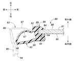
- FIG. 10 is a cross-sectional view taken along the line IX-IX in FIG. 9 and showing a rear edge portion of the window module.
- FIG. 11 is a perspective view showing a form after the molding is assembled.
- FIG. 12 is a perspective view showing a form before the molding 10 is assembled.
- a front door opening 71 is formed on the front side of the vehicle body 70.
- the front door opening 71 is closed openably and closably by a front side door 72 supported on the vehicle body 70 via a hinge.
- the front side door 72 has a door panel portion 73 and a frame-shaped door sash portion 74 provided on the upper portion of the door panel portion 73.
- the front side edge 75 of the door sash part 74 is provided to be biased rearward from the front side edge 76 of the door panel part 73.
- a triangular triangular window opening 79 is formed between the front door opening 71 and the front pillar 78, and the triangular window opening 79 is closed so as not to be opened and closed by a window module 80 as a front fix window.
- the window module 80 includes a triangular window panel 81 and a molding 86 formed and joined along each edge 83, 84, 85 of the window panel 81.
- the window panel 81 is fastened to the vehicle body 70 by a fastener (clip) not shown.
- the material of the window panel 81 and the molding 86 and the forming method of the molding 86 are the same as those of the window panel 81 and the molding 86 according to the first embodiment.
- the window panel 81 connects the lower edge 83 extending in the front-rear direction, the rear edge 84 extending substantially vertically upward from the rear end of the lower edge 83, and the upper end of the front edge and the rear edge 84 of the lower edge 83. And an upper front edge 85 extending in an inclined manner.
- the rear edge portion 84 is disposed so as to extend in parallel with the front side edge 75 of the door sash portion 74 in the closed state.
- the molding 86 is provided at the lower edge 83 and the upper front edge 85 so as to wrap the front surface 88 (vehicle outer surface), the end surface 89, and the rear surface 90 (vehicle inner surface) of each edge 83, 85.
- the molding 86 at the rear edge 84 has a base 92 provided so as to wrap the front surface 88, the end surface 89, and the back 90 of the rear edge 84, and a thin plate shape protruding from the base 92.
- Lip part 93 protrusion part. Both the base 92 and the lip 93 extend over the entire rear edge 84.
- the lip portion 93 is formed in a cylindrical shape by being locked in a locking groove 95 formed in the base portion 92 in a locking piece portion 94 protruding from the tip portion.
- the lip portion 93 includes a lip base portion 97 extending from the portion corresponding to the end face 89 of the rear edge portion 84 in the base portion 92 to the outside (rear) of the window panel 81. And a lip tip 99 extending from the tip of the lip base 97 to the back surface 90 side of the window panel 81 via a bent portion 98 bent at a substantially right angle.
- the locking piece 94 protrudes from the lip tip 99 in a direction substantially perpendicular to the lip tip 99.
- the molding 86 is outsert-molded on the window panel 81 in a state where the locking piece 94 is detached from the locking groove 95.
- a plurality of slits 101 (easy deformable portions) cut from the edge of the lip toward the bent portion 98 are formed in the lip tip 99 along the longitudinal direction of the lip tip 99.
- the slit 101 is formed so as to penetrate in the thickness direction of the lip tip 99 and divides the locking piece 94 in the longitudinal direction.
- the locking groove 95 extends along the longitudinal direction of the base portion 92 at a portion corresponding to the back surface 90 of the rear edge portion 84 in the base portion 92.
- the lip portion 93 When the locking piece portion 94 is locked in the locking groove 95, the lip portion 93 has a cylindrical shape so that the bent portion 98 forms a side end portion that protrudes most from the rear edge portion 84.
- the lip tip portion 99 When the lip portion 93 has a cylindrical shape, the lip tip portion 99 is disposed on the vehicle inner side of the lip base portion 97 when viewed from the vehicle outer side, and the slit 101 is not visible from the vehicle outer side.
- the cylindrical lip portion 93 elastically contacts the front edge 75 of the door sash portion 74 and seals the gap between the window panel 81 and the door sash portion 74.
- the window module 80 according to the second embodiment is provided with the slit 101 functioning as an easily deformable portion at the lip tip portion 99, so that the tensile force present in the lip portion 93 after molding is the same as in the first embodiment described above. Stress can be relaxed. By reducing the tensile stress generated in the lip portion 93, the cylindrical lip portion 93 is maintained in a predetermined shape. If the slit 101 is not provided and a relatively large tensile stress exists in the lip portion 93, the deformation mode of the lip portion 93 changes due to the influence of the tensile stress, and the cylindrical cross-sectional shape changes. To do. For example, in the cylindrical state, if the bent portion 98 is biased toward the vehicle inner side than the intended position, there is a possibility that elastic contact with the front side edge 75 of the door sash portion 74 may not be achieved.
- the slit 101 in the second embodiment can be replaced with another easily deformable structure such as a thin-walled portion or a bellows structure, as in the first embodiment.
- the locking piece 94 provided at the lip tip 99 may be provided at the base 92, and the locking groove 95 provided at the base 92 may be provided at the lip tip 99.
- a locking hole which is a through hole may be provided in the lip tip 99 in order to lock the locking piece 94.
- the present invention is not limited to the above-described embodiment, and can be widely modified.
- the protruding portion 16 may be formed in a simple plate shape that protrudes linearly and elastically contacts the hole wall of the opening.
- the example in which the window module according to the present invention is applied to a member that closes the sunroof opening or the example in which the window module according to the present invention is applied to a front fix window has been described. The same applies to other window modules.
- window panel 86 ... molding, 92 ... base part, 93 ... lip part (protruding part), 94 ... locking piece part, 95 ... locking groove (locking hole), 97 ... lip base part (base end side part), 98 ... bent part, 99 ... lip tip part (tip side part), 101 ... slit
Landscapes
- Engineering & Computer Science (AREA)
- Mechanical Engineering (AREA)
- Seal Device For Vehicle (AREA)
Abstract
【課題】 ウインドウパネルの縁部において成形されたモールを有するウインドウモジュールにおいて、成形後の収縮による変形を抑制する。 【解決手段】 ウインドウパネル7と、ウインドウパネルの縁部8において成形され、縁部に結合されたモール10とを有するウインドウモジュール5であって、モールは、縁部に沿って延在し、縁部に結合された基部15と、基部から突出すると共に、基部に沿って延在する突出部16とを有し、突出部は、縁部に沿った長手方向における少なくとも一部分に、他の部分よりも長手方向に変形が容易な易変形部41を有するようにした。
Description
本発明は、車両等の開口部に設けられるウインドウモジュールに関する。
従来、自動車の車体に形成されたサンルーフ開口等の窓開口を、ウインドウモジュールによって閉じたものがある。ウインドウモジュールは、板ガラス又は樹脂板からなるウインドウパネルと、ウインドウパネルの縁部に結合された樹脂製のモールとを有する。モールは、熱可塑性樹脂を素材とし、ウインドウパネルの縁部において成形され、当該縁部に結合される。モールは、窓開口の縁部に弾接することによって、ウインドウパネルと窓開口との隙間をシールする。サンルーフ開口を開閉するウインドウモジュールとして、ウインドウパネルの縁部にモールを成形し、モールに長手方向に延在する係止溝を形成し、係止部を側部に備えた中空のウェザーストリップを用意し、係止部と係止溝との係合によってウェザーストリップをモールに沿うように配置したものがある(例えば、特許文献1)。特許文献1に係るウインドウモジュールは、可撓性に優れたウェザーストリップをウインドウパネルの縁部に取り付けるために、接着剤を使用する必要がない。
ウインドウパネルの縁部に沿って成形されたモールは、成形後の温度低下に伴って収縮する。このとき、モールは、ウインドウパネルが収縮しないため、ウインドウパネルに近接した部分では収縮量が小さくなる一方、ウインドウパネルから離間した部分では収縮量が大きくなる。そのため、モール内のウインドウパネルから離間した部分は、ウインドウパネルに近接した部分に引っ張られることによって引張応力が発生する。発生した引張応力が大きい場合には、モールに変形(歪み)が生じ、モール及び係止溝の形状が予定された形状から変化する。係止溝が変形すると、係止溝とウェザーストリップの係止部との間にがた付きが生じ、ウェザーストリップの保持力が低下する。特に、ウインドウパネルの縁部が湾曲したコーナ部においては、モールの長手方向に生じる引張応力の合力がモールの湾曲中心側を向き、その方向への変形量が大きくなる。以上の問題に対して、モールの成形後の変形量を予測して成形型を作成し、変形が発生した状態でモールが適正な形状となるようにすることが考えられる。しかしながら、変形量を見込んで成形型を製作するには、多くの計算や試作型の作成が必要となり、労力及びコスト面での負担が大きい。
本発明は以上の背景を鑑みてなされたものであって、ウインドウパネルの縁部において成形されたモールを有するウインドウモジュールにおいて、成形後の収縮による変形を抑制することを課題とする。
上記課題を解決するために、本発明は、ウインドウパネル(7)と、前記ウインドウパネルの縁部(8)において成形され、前記縁部に結合されたモール(10)とを有するウインドウモジュール(5)であって、前記モールは、前記縁部に沿って延在し、前記縁部に結合された基部(15)と、前記基部から突出すると共に、前記基部に沿って延在する突出部(16)とを有し、前記突出部は、前記縁部に沿った長手方向における少なくとも一部分に、他の部分よりも前記長手方向に変形が容易な易変形部(41)を有することを特徴とする。ここでのウインドウパネルの縁部とは、ウインドウパネルの主面に対向する方向から見た際にウインドウパネルの輪郭を形成する部分であり、直線状に延びる部分やコーナ部(角部)、湾曲しつつ延びる部分等を含み、環状に形成されている。モールはウインドウパネルの縁部の少なくとも一部に設けられており、例えば直線状部分のみや、或いはコーナ部のみに設けられていてもよく、ある一例では縁部の全域に設けられ、環状となっていてもよい。ウインドウパネルの縁部に沿った長手方向とは、直線状に延びる部分やコーナ部、湾曲しつつ延びる部分等に沿った方向をいう。
この構成によれば、易変形部が変形して応力を緩和することによって、突出部の他の部分に加わる応力が低減され、変形が抑制される。
また、上記発明において、係止部(32)を備えたウェザーストリップ(11)を更に有し、前記突出部は、前記ウェザーストリップの前記係止部を係止する係止溝(27)を形成することを特徴とする。
この構成によれば、成形後にモールに応力が生じる場合にも、易変形部が変形することによって突出部に生じる応力が低減されるため、係止溝は予定の形状を維持することができる。これにより、係止溝は、ウェザーストリップの係止部を適切に保持することができる。
また、上記発明において、前記ウインドウパネルの前記縁部は、弧状に湾曲したコーナ部(13)を有し、前記易変形部は、前記コーナ部の湾曲が始まる端部(42、43)を含む位置に配置されていることを特徴とする。
この構成によれば、成形後の収縮に起因したコーナ部における突出部の変形が抑制される。ウインドウパネルの縁部の内で直線状に延びる部分を直線部とすると、直線部においては成形後の収縮に起因して突出部には長手方向に沿った方向に引張応力が加わる。ウインドウパネルの面に沿ってウインドウパネルの内方に向う方向を内側、外方に向う方向を外側とすると、直線部に対応した突出部は、引張応力の方向がウインドウパネルの内側-外側方向に直交するため、ウインドウパネルの内側-外側方向への変形量は比較的小さい。一方、コーナ部では、突出部の延在方向が湾曲しているため、突出部の長手方向に加わる引張応力は、合力として突出部を湾曲の中心側(ウインドウパネルの内側)に変形させるように作用する。そのため、コーナ部における突出部は変形量が比較的大きくなる。易変形部はコーナ部の両端部において引張応力を緩和し、コーナ部に配置された突出部の引張応力を低減するため、突出部が予定の形状に維持される。特に、コーナ部の湾曲が始まる端部を含む位置に易変形部を設けることによって、コーナ部に隣接する直線部等において発生する引張応力を遮断し、コーナ部に加わらないようにすることができるため、突出部の変形抑制効果が大きい。
また、上記発明において、前記基部(92)及び前記突出部(93)の一側には、その長手方向に沿って係止孔(95)が設けられ、前記基部及び前記突出部の他側には、その長手方向に沿って前記係止孔に係止される係止片(94)が設けられ、前記係止片が前記係止孔に係止されることによって、前記突出部は筒形状をなすことを特徴とする。
この構成によれば、易変形部によって引張応力が低減された突出部は、予定の形状の筒形を維持することができる。
また、上記発明において、前記易変形部は、前記係止孔に前記係止片が係止された状態において、前記ウインドウパネルの表面側から見て前記突出部の基端側部分(97)に隠蔽される先端側部分(99)に配置されることを特徴とする。
この構成によれば、易変形部は車外側から視認することができないため、モールの外観に影響を与えることがない。
また、上記発明において、前記易変形部は、前記突出部の他の部分よりも肉厚が薄いことを特徴とする。また、前記易変形部は、蛇腹構造を有することを特徴とする。また、前記易変形部は、スリットを有することを特徴とする。
これらの構成によれば、易変形部は、モールの長手方向に対して伸縮が容易になる。
以上の構成によれば、ウインドウパネルの縁部において成形されたモールを有するウインドウモジュールにおいて、成形後の収縮による変形を抑制することができる。
以下、図面を参照して、本発明のウインドウモジュールを車両の開口に設け2つの実施形態について詳細に説明する。以下の説明では、車両の進行方向を基準として各方向を定める。
図1は、第1実施形態に係るウインドウモジュールがサンルーフ開口に設けられた車両の上部構造を示す斜視図である。図1に示すように、車体1のルーフ2には、車外と車内(車室内)とを連通する略四角形のサンルーフ開口3が形成されている。サンルーフ開口3は、ウインドウモジュール5によって開閉可能に閉じられる。サンルーフ開口3の縁部8には、開閉機構(不図示)が設けられており、ウインドウモジュール5はこの開閉機構によって支持される。開閉機構は、例えば、サンルーフ開口3の左右の縁部に前後に沿って設けられたガイドレールと、ガイドレールにスライド移動可能に支持され、ウインドウモジュール5を支持するスライダと、スライダをガイドレールに対して移動させるアクチュエータとを有している。ウインドウモジュール5は、開閉機構によって、例えば、サンルーフ開口3に嵌り込む閉位置と、サンルーフ開口3に対して車外側かつ後方に位置する開位置との間で移動する。
図2は、図1のII-II断面図であって、ウインドウモジュールの縁部を示す断面図である。図2に示すように、ウインドウモジュール5は、ウインドウパネル7と、ウインドウパネル7の縁部8に結合されたモール10と、モール10に支持されたウェザーストリップ11とを有している。ウインドウパネル7は、ガラスや樹脂等から形成された略長方形の板状部材である。図3は、ウェザーストリップを省略してウインドウパネル及びモールを示す斜視図である。図3に示すように、ウインドウパネル7の長方形の縁部8に形成されるコーナ部13は、隣り合う側縁同士を滑らかに繋ぐように弧状に湾曲している。ウインドウパネル7は、樹脂製のファスナ(クリップ)や接着剤等によって開閉機構のスライダに固定される。
モール10は、ウインドウパネル7の縁部8に沿って設けられ、枠体を形成している。モール10は、ウインドウパネル7の縁部8に熱可塑性樹脂をアウトサート成形することによって、ウインドウパネル7と一体に形成されている。モール10とウインドウパネル7との界面には、接着性を高めるために接着剤(プライマー、不図示)が介在している。モール10は、例えば、ポリスチレン系エラストマー(TPS)や、ポリオレフィン系エラストマー(TPO)、ポリビニル系エラストマー(PVC)等であってよい。接着剤は、ウインドウパネル7とモール10とを良好に接着できるものであれば特に限定されるものではないが、例えば、ウインドウパネル7を板ガラス、モール10をポリスチレン系エラストマーとした場合、オレフィン系の接着剤を用いることができる。
図2に示すように、モール10は、ウインドウパネル7の縁部8に接着された基部15と、基部15から突出した突出部16とを有している。基部15は、ウインドウパネル7の厚み方向(上下)に延在してウインドウパネル7の端面17の全域を覆う基部上部18と、基部上部18の下端から縁部8の下面19(裏面、車内側面)に沿って延在した基部下部21とを有し、断面が略L字状に形成されている。基部15は、基部上部18及び基部下部21の両方においてウインドウパネル7に結合されている。基部上部18の上端面(車外側端面)は、ウインドウパネル7の上面(表面、車外側面)と同一面(フラッシュサーフェス)に形成されている。基部上部18及び基部下部21は、ウインドウパネル7の縁部8に沿って延在し、閉環状となっている。
ここで、ウインドウパネル7の板面と平行な方向であって、ウインドウパネル7の中央側に向う方向をウインドウパネル7の内方向(図2における右側)、相反する方向をウインドウパネル7の外方向(図2における左側)とする。突出部16は、基部下部21の内端部から下方かつウインドウパネル7の外方向へと傾斜して突出した後、屈曲してウインドウパネル7の外方向に延びるフック部25と、フック部25の先端部からウインドウパネル7の外方かつ下方へと延びるガーター部26とを有している。
フック部25は、基部下部21との間に、ウインドウパネル7の外方向に向かって開口した係止溝27を形成する。基部下部21の外端部には下方に突出する上係止凸部28が形成されており、フック部25の先端部には上係止凸部28と対向するように上方に突出する下係止凸部29が形成されている。上係止凸部28及び下係止凸部29は、係止溝27の開口端部の上下方向における幅を絞っている。下係止凸部29は、上係止凸部28に対して、左右方向(ウインドウパネル7の内外方向)における長さが小さくなっている。係止溝27、上係止凸部28及び下係止凸部29は、モール10の長手方向に沿って延設され、係止溝27は環状溝となっている。
ウェザーストリップ11は、筒状のシール部31と、シール部31から突出した係止部32とを有している。係止部32は、先端部に拡頭部33を有し、係止溝27に突入して上係止凸部28及び下係止凸部29に係止される。係止溝27は、係止部32をがた付きなく支持するために、上下方向における長さが係止部32の上下方向における長さよりも小さく形成され、モール10の弾性を利用して係止部32を上下から挟圧することが好ましい。
シール部31及び係止部32は、ウインドウパネル7の縁部8に沿って延在するように、環状に形成されている。シール部31の係止部32が設けられた部分であるシール基部35及び係止部32と、シール部31のシール基部35以外の他の部分であるシール先端部36とは、異なる樹脂から形成されている。シール先端部36は、シール基部35よりも可撓性が高い軟質のゴム材や樹脂を素材とし、シール基部35及び係止部32はシール先端部36よりも可撓性が低いゴム材や樹脂を素材とする。シール先端部36と、シール基部35及び係止部32とは、例えば二色成形によって一体的に形成される。シール部31は、基部上部18の上端面と同一面(フラッシュサーフェス)となる外表面を有する。シール部31は、ウインドウモジュール5が閉位置にある場合に、サンルーフ開口3の縁壁38に弾接し、ウインドウモジュール5とサンルーフ開口3との間をシールする。
ガーター部26は、サンルーフ開口3の縁部8に形成された集水溝39の上方に配置され、ウェザーストリップ11のシール部31とサンルーフ開口3の縁壁38との間を通過した雨水を集水溝39に導く。
図3に示すように、縁部8に沿った突出部16の長手方向における適所には、易変形部41が設けられている。本実施形態では、易変形部41は、ウインドウパネル7のコーナ部13の湾曲が始まる始端部42及び湾曲が終わる終端部43、すなわちコーナ部13の両端に配置されたR止まり部を含む位置に配置されている。易変形部41は、長手方向における両端の一方が、始端部42又は終端部43と対応する位置に配置されてもよく、始端部42又は終端部43を長手方向に跨ぐにように配置されてもよい。
図4は図3のIV-IV断面図であり、図5は図3のV-V断面図である。図4及び図5に示すように、易変形部41は、ガーター部26の先端縁からフック部25の中間部へと延びる薄肉部45である。薄肉部45は、ガーター部26及びフック部25の車内側面に、ガーター部26の先端縁から延びる凹溝46を設けることによって形成されている。薄肉部45は、両隣のガーター部26に対してウインドウパネル7の外方向に膨出した湾曲形状となっている。他の実施形態では、凹溝46は、ガーター部26及びフック部25の車外側面に形成されてもよく、薄肉部45はウインドウパネル7の内方向に膨出した湾曲形状となっていてもよい。凹溝46の側壁は、ガーター部26及びフック部25の厚み方向と平行に延びていてもよいし、厚み方向に対して傾斜し、薄肉部45とガーター部26及びフック部25の表面とを滑らかな曲面で連続させていてもよい。また、薄肉部45は、フック部25の突出方向における全域にわたって形成されていてもよい。
薄肉部45は、例えばガーター部26の肉厚が2.0~3.0mmである場合に、1.0mmであることが好ましい。また、薄肉部45は、モール10の長手方向において約10mmの幅を有することが好ましい。
薄肉部45は、他のガーター部26及びフック部25よりも肉厚が薄く、湾曲形状をなすため、モール10の長手方向においてガーター部26及びフック部25よりも伸張及び収縮(変形)し易くなっている。
以上のウインドウモジュール5では、モール10はウインドウパネル7の縁部8において成形され、結合される。そのため、モール10は、成形後の温度低下に伴って収縮する。このとき、基部15は収縮しないウインドウモジュール5に結合されているため収縮量が小さく、ウインドウモジュール5から離間した突出部16は基部15よりも大きく収縮する。また、突出部16は、基部15から離間するほど収縮量が大きくなる。モール10は縁部8に沿って延在しているため、突出部16はモール10の長手方向において収縮量が大きくなる。一方、突出部16は、収縮しない基部15と一体となっているため、基部15に引っ張られる。これにより、突出部16には引張応力が発生する。突出部16は、易変形部41の薄肉部45において長手方向に伸張することによって、他のガーター部26やフック部25に加わる引張応力を低減する。これにより、易変形部41を除く突出部16は引張応力による変形が生じ難くなり、係止溝27の形状は予定の形状に維持される。
第1実施形態に係るウインドウモジュール5は、ウインドウパネル7のコーナ部13の湾曲の始端部42及び終端部43に対応した部分に易変形部41を有するため、コーナ部13に配置された突出部16に引張応力が加わり難くなり、変形が抑制される。仮に、易変形部41が存在しない場合には、コーナ部13において湾曲した突出部16に、突出部16の長手方向に加わる引張張力が湾曲の中心側に向う力として作用し、ガーター部26を含む突出部16を湾曲の中心側へと変形させることになる。
第1実施形態では、易変形部41をコーナ部13の両端部に対応する部分に配置した例を説明したが、易変形部41は突出部16がウインドウパネル7の側縁に沿って直線状に延在する部分の適所に設けられてもよいし、コーナ部13に対応して突出部16が湾曲した部分に設けられてもよい。また、易変形部41の数は、適宜選択することができる。
第1実施形態に係る易変形部は、成形後の収縮に起因する応力を緩和するだけでなく、外気温の変動に起因してモールに発生する応力も同様に緩和する。また、易変形部は、機械的な接触等によってモールの一部に生じた応力が他の部分に伝達されないように遮断する。
図6は、モールの一部変形実施例を示す断面図である。以上のように構成した易変形部41の一部変形例として、図6に示すように、薄肉部45の形状を、湾曲形状から直線状に変更してもよい。図6に示す薄肉部45の断面位置は、図4の断面に対応する。薄肉部45は、湾曲形状を採用しなくても、突出部26の他の部分に対して肉厚が薄いため、突出部26の長手方向に伸縮(変形)が容易であり、易変形部41として機能することができる。このようにすると、突出部16の外面形状を一定とすることができ、美観を高めることができる。
図7及び図8は、易変形部の他の変形実施例を示す断面図である。図7に示す変形実施例では、易変形部51は、突出部16の長手方向に伸縮が容易な蛇腹構造52を有している。蛇腹構造52は、断面が突出部16の長手方向においてジグザグ形又は波形に屈曲した板状をなす。蛇腹構造52を構成する部材の肉厚は、他のガーター部26及びフック部25の肉厚よりも薄いことが好ましい。蛇腹構造52は、突出部16に発生する引張応力に応じて伸張し、易変形部51以外の突出部16に加わる引張応力を低減し、変形を抑制する。
図8に示す変形実施例では、易変形部55は、ガーター部26の突出端からフック部25の突出方向における中間部にかけて切り込まれたスリット56を有している。突出部16に長手方向に沿った引張応力が発生する際には、スリット56は突出部16の長手方向において拡開される。これにより、引張応力が緩和され、易変形部41以外の突出部16の変形が抑制される。
次に、図9~図12を参照して、本発明のウインドウモジュールを車両のフロントフィックスウインドウに適用した第2実施形態について詳細に説明する。図9は、第2実施形態に係るウインドウモジュールが三角窓開口に設けられた車両の前部構造を示す斜視図である。図10は、図9のIX-IX断面図であって、ウインドウモジュールの後縁部を示す断面図である。図11は、モールの組立後の形態を示す斜視図である。図12は、モール10の組立前の形態を示す斜視図である。
図9に示すように、車体70の側部前側には、前部ドア開口71が形成されている。前部ドア開口71は、車体70にヒンジを介して支持されたフロントサイドドア72によって開閉自在に閉じられる。フロントサイドドア72は、ドアパネル部73と、ドアパネル部73の上部に設けられた枠状のドアサッシュ部74とを有している。ドアサッシュ部74の前側縁75は、ドアパネル部73の前側縁76よりも後方に偏倚して設けられている。
前部ドア開口71とフロントピラー78との間には三角形状の三角窓開口79が形成されており、三角窓開口79はフロントフィックスウインドウとしてのウインドウモジュール80によって開閉不能に閉じられる。ウインドウモジュール80は、三角形のウインドウパネル81と、ウインドウパネル81の各縁部83、84、85に沿って成形され、結合されたモール86とを有している。ウインドウパネル81は、図示しないファスナ(クリップ)によって車体70に締結される。ウインドウパネル81及びモール86の材質、モール86の形成方法は、第1実施形態に係るウインドウパネル81及びモール86と同様である。
ウインドウパネル81は、前後に延びる下縁部83と、下縁部83の後端から上方へと略鉛直に延びる後縁部84と、下縁部83の前端及び後縁部84の上端を繋ぐように傾斜して延びる上前縁部85とを有している。後縁部84は、閉状態におけるドアサッシュ部74の前側縁75と距離をおいて平行に延びるように配置される。
モール86は、下縁部83及び上前縁部85において、各縁部83、85の表面88(車外面)、端面89、及び裏面90(車内面)を包むように設けられている。図10及び図11に示すように、後縁部84におけるモール86は、後縁部84の表面88、端面89、及び裏面90を包むように設けられた基部92と、基部92から突出した薄板状のリップ部93(突出部)とを有している。基部92及びリップ部93は、共に後縁部84の全域にわたって延在している。リップ部93は、先端部に突設された係止片部94において基部92に形成された係止溝95に係止されることによって筒形の形態になる。
図10中の破線及び図12に示すように、リップ部93は、基部92における後縁部84の端面89に対応した部分からウインドウパネル81の外方向(後方)へと延びたリップ基部97と、略直角に屈曲した屈曲部98を介してリップ基部97の先端からウインドウパネル81の裏面90側へと延びたリップ先端部99とを有している。係止片部94は、リップ先端部99から略直交する方向に突出している。これらの図に示すように、係止片部94が係止溝95から離脱した状態に、モール86がウインドウパネル81にアウトサート成形される。
図11及び図12に示すように、リップ先端部99には、その先端縁から屈曲部98側へと切り込まれたスリット101(易変形部)がリップ先端部99の長手方向にわたって複数形成されているスリット101は、リップ先端部99の厚み方向に貫通するように形成され、係止片部94を長手方向において分断している。係止溝95は、基部92における後縁部84の裏面90に対応した部分に基部92の長手方向に沿って延設されている。
係止片部94が係止溝95に係止されることによって、リップ部93は、屈曲部98が後縁部84から最も突出した側端部を形成するように筒形となる。リップ部93が筒形となった場合には、車外側から見て、リップ先端部99はリップ基部97の車内側に配置され、スリット101は車外側から視認できない。筒形となったリップ部93は、ドアサッシュ部74の前側縁75に弾接し、ウインドウパネル81とドアサッシュ部74との隙間をシールする。
第2実施形態に係るウインドウモジュール80は、リップ先端部99に易変形部として機能するスリット101を設けたことによって、上記した第1実施形態と同様に、成形後のリップ部93に存在する引張応力を緩和することができる。リップ部93に発生する引張応力が低減されることによって、筒形をなすリップ部93が所定の形状に維持される。仮に、スリット101を設けず、リップ部93に比較的大きな引張応力が存在している場合には、引張応力の影響を受けてリップ部93の変形態様が変化し、筒形の断面形状が変化する。例えば、筒形状態において、屈曲部98が所期の位置よりも車内側に偏倚すると、ドアサッシュ部74の前側縁75との弾接が達成されなくなる虞がある。
第2実施形態におけるスリット101は、第1実施形態と同様に、薄肉部や蛇腹構造等の他の変形が容易な構造に置換することができる。また、リップ先端部99に設けた係止片部94を基部92に設け、基部92に設けた係止溝95をリップ先端部99に設けてもよい。また、基部92に係止片部94を設ける場合には、係止片部94を係止するためにリップ先端部99に貫通孔である係止孔を設けてもよい。
以上で具体的実施形態の説明を終えるが、本発明は上記実施形態に限定されることなく幅広く変形実施することができる。例えば、突出部16(リップ部93)は、直線状に突出し、開口の孔壁に弾接する単純な板片状に形成されてもよい。また、上記の実施形態では、本発明に係るウインドウモジュールを、サンルーフ開口を閉じる部材に適用した例や、フロントフィックスウインドウに適用した例について説明したが、本発明に係るウインドウモジュールはリアクォーターウインドウ等の他のウインドウモジュールにも同様に適用することができる。
3…サンルーフ開口、5…ウインドウモジュール、7…ウインドウパネル、8…縁部、10…モール、11…ウェザーストリップ、13…コーナ部、15…基部、16…突出部、25…フック部、26…ガーター部、27…係止溝、31…シール部、32…係止部、41…易変形部、42…始端部、43…終端部、45…薄肉部、46…凹溝、51…易変形部、52…蛇腹構造、55…易変形部、56…スリット、79…三角窓開口、80…ウインドウモジュール、81…ウインドウパネル、86…モール、92…基部、93…リップ部(突出部)、94…係止片部、95…係止溝(係止孔)、97…リップ基部(基端側部分)、98…屈曲部、99…リップ先端部(先端側部分)、101…スリット
Claims (9)
- ウインドウパネルと、前記ウインドウパネルの縁部において成形され、前記縁部に結合されたモールとを有するウインドウモジュールであって、
前記モールは、
前記縁部に沿って延在し、前記縁部に結合された基部と、
前記基部から突出すると共に、前記基部に沿って延在する突出部と
を有し、
前記突出部は、前記縁部に沿った長手方向における少なくとも一部分に、他の部分よりも前記長手方向に変形が容易な易変形部を有することを特徴とするウインドウモジュール。 - 係止部を備えたウェザーストリップを更に有し、
前記突出部は、前記ウェザーストリップの前記係止部を係止する係止溝を形成することを特徴とする請求項1に記載のウインドウモジュール。 - 前記ウインドウパネルの前記縁部は、弧状に湾曲したコーナ部を有し、
前記易変形部は、前記コーナ部の湾曲が始まる端部を含む位置に配置されていることを特徴とする請求項2に記載のウインドウモジュール。 - ウインドウパネルと、前記ウインドウパネルの縁部において成形され、前記縁部に結合されたモールとを有するウインドウモジュールであって、
前記モールは、
前記縁部に沿って延在し、前記縁部に結合された基部と、
前記基部から突出すると共に、前記基部に沿って延在する突出部と
を有し、
前記ウインドウパネルの前記縁部は、弧状に湾曲したコーナ部を有し、
前記突出部は、前記縁部に沿った長手方向における少なくとも一部分に、他の部分よりも前記長手方向に変形が容易な易変形部を有し、
前記易変形部は、前記コーナ部の湾曲が始まる端部を含む位置に配置されていることを特徴とするウインドウモジュール。 - 前記基部及び前記突出部の一側には、その長手方向に沿って係止孔が設けられ、
前記基部及び前記突出部の他側には、その長手方向に沿って前記係止孔に係止される係止片が設けられ、
前記係止片が前記係止孔に係止されることによって、前記突出部は筒形状をなすことを特徴とする請求項1に記載のウインドウモジュール。 - 前記易変形部は、前記係止孔に前記係止片が係止された状態において、前記ウインドウパネルの表面側から見て前記突出部の基端側部分に隠蔽される先端側部分に配置されることを特徴とする請求項5に記載のウインドウモジュール。
- 前記易変形部は、前記突出部の他の部分よりも肉厚が薄いことを特徴とする請求項1~請求項6のいずれか1つの項に記載のウインドウモジュール。
- 前記易変形部は、蛇腹構造を有することを特徴とする請求項1~請求項6のいずれか1つの項に記載のウインドウモジュール。
- 前記易変形部は、スリットを有することを特徴とする請求項1~請求項6のいずれか1つの項に記載のウインドウモジュール。
Priority Applications (2)
| Application Number | Priority Date | Filing Date | Title |
|---|---|---|---|
| CN201380064288.2A CN104837660B (zh) | 2012-12-10 | 2013-11-06 | 车窗组件 |
| US14/442,419 US9776490B2 (en) | 2012-12-10 | 2013-11-06 | Window module |
Applications Claiming Priority (2)
| Application Number | Priority Date | Filing Date | Title |
|---|---|---|---|
| JP2012-269661 | 2012-12-10 | ||
| JP2012269661A JP2014113926A (ja) | 2012-12-10 | 2012-12-10 | ウインドウモジュール |
Publications (1)
| Publication Number | Publication Date |
|---|---|
| WO2014091668A1 true WO2014091668A1 (ja) | 2014-06-19 |
Family
ID=50933977
Family Applications (1)
| Application Number | Title | Priority Date | Filing Date |
|---|---|---|---|
| PCT/JP2013/006543 Ceased WO2014091668A1 (ja) | 2012-12-10 | 2013-11-06 | ウインドウモジュール |
Country Status (4)
| Country | Link |
|---|---|
| US (1) | US9776490B2 (ja) |
| JP (1) | JP2014113926A (ja) |
| CN (1) | CN104837660B (ja) |
| WO (1) | WO2014091668A1 (ja) |
Cited By (1)
| Publication number | Priority date | Publication date | Assignee | Title |
|---|---|---|---|---|
| US20130033071A1 (en) * | 2011-08-01 | 2013-02-07 | Nihon Plast Co., Ltd. | Structure of mounting cowl-top cover |
Families Citing this family (5)
| Publication number | Priority date | Publication date | Assignee | Title |
|---|---|---|---|---|
| JP7183903B2 (ja) * | 2019-03-26 | 2022-12-06 | 豊田合成株式会社 | ルーフウェザストリップ |
| DE102019124844B3 (de) * | 2019-09-16 | 2020-10-08 | Webasto SE | Fahrzeugdach und Dachanordnung |
| DE102019126860A1 (de) * | 2019-10-07 | 2021-04-08 | Webasto SE | Deckel zum Verschließen einer Öffnung in einer Fahrzeugkarosserie |
| CN219467506U (zh) * | 2022-10-11 | 2023-08-04 | 福州明芳汽车部件工业有限公司 | 天窗装置 |
| EP4407216A1 (en) * | 2023-01-30 | 2024-07-31 | BDR Thermea Group B.V. | Seal for a heat pump casing |
Citations (5)
| Publication number | Priority date | Publication date | Assignee | Title |
|---|---|---|---|---|
| JPH04317818A (ja) * | 1991-04-15 | 1992-11-09 | Tokai Kogyo Kk | ウインドモールおよびその製造方法 |
| JPH0657779U (ja) * | 1993-01-22 | 1994-08-12 | 日産ディーゼル工業株式会社 | キャブのシール構造 |
| JP2005008048A (ja) * | 2003-06-19 | 2005-01-13 | Asahi Glass Co Ltd | ウェザストリップの保持構造 |
| JP2010095129A (ja) * | 2008-10-16 | 2010-04-30 | Yachiyo Industry Co Ltd | サンルーフ装置 |
| WO2012109402A1 (en) * | 2011-02-11 | 2012-08-16 | Pilkington Group Limited | Encapsulated vehicle window assembly with interlocking seal and method of bonding same in vehicle body opening |
Family Cites Families (12)
| Publication number | Priority date | Publication date | Assignee | Title |
|---|---|---|---|---|
| DE7112523U (de) * | 1971-04-01 | 1971-07-01 | Gebr Happich Gmbh | Fensterfuehrungsschiene insbesondere fuer fahrzeugfenster |
| JP2502078B2 (ja) * | 1987-03-04 | 1996-05-29 | 鬼怒川ゴム工業株式会社 | 自動車用ウインドモ−ル |
| US5170587A (en) * | 1990-09-03 | 1992-12-15 | Toyoda Gosei Co., Ltd. | Weatherstrip for automotive vehicle |
| US6224145B1 (en) * | 1998-10-30 | 2001-05-01 | Inoac Corporation | Roof molding for an automobile and method of trimming the same |
| US6286898B1 (en) * | 2000-08-11 | 2001-09-11 | Vuteq Corporation | Vehicle sunroof with weatherstrip mounting flange |
| CN102745048B (zh) * | 2000-10-10 | 2014-12-17 | 法国圣戈班玻璃厂 | 包括用来将玻璃安装在窗洞中的成型带的窗玻璃的应用 |
| US6513854B2 (en) * | 2001-02-15 | 2003-02-04 | Centre Luxembourgeois De Recherches Pour Le Verre Et La Ceramique S.A. (C.R.V.C.) | Method of applying extruded profile to corners of a window glazing |
| JP3886861B2 (ja) * | 2001-08-14 | 2007-02-28 | 鬼怒川ゴム工業株式会社 | ウインドモール |
| JP2003211967A (ja) | 2002-01-21 | 2003-07-30 | Honda Motor Co Ltd | サンルーフ装置のガラスパネル |
| JP4616699B2 (ja) * | 2005-05-27 | 2011-01-19 | 日本板硝子株式会社 | 枠体付き板状部材 |
| FR2898181B1 (fr) | 2006-03-01 | 2008-04-18 | Rehau Sa | Profile extrude, colle, presentant un surmoulage d'angle et procede de realisation d'un tel profile. |
| JP4902395B2 (ja) * | 2007-03-08 | 2012-03-21 | 八千代工業株式会社 | ルーフパネルの排水構造 |
-
2012
- 2012-12-10 JP JP2012269661A patent/JP2014113926A/ja active Pending
-
2013
- 2013-11-06 CN CN201380064288.2A patent/CN104837660B/zh active Active
- 2013-11-06 WO PCT/JP2013/006543 patent/WO2014091668A1/ja not_active Ceased
- 2013-11-06 US US14/442,419 patent/US9776490B2/en not_active Expired - Fee Related
Patent Citations (5)
| Publication number | Priority date | Publication date | Assignee | Title |
|---|---|---|---|---|
| JPH04317818A (ja) * | 1991-04-15 | 1992-11-09 | Tokai Kogyo Kk | ウインドモールおよびその製造方法 |
| JPH0657779U (ja) * | 1993-01-22 | 1994-08-12 | 日産ディーゼル工業株式会社 | キャブのシール構造 |
| JP2005008048A (ja) * | 2003-06-19 | 2005-01-13 | Asahi Glass Co Ltd | ウェザストリップの保持構造 |
| JP2010095129A (ja) * | 2008-10-16 | 2010-04-30 | Yachiyo Industry Co Ltd | サンルーフ装置 |
| WO2012109402A1 (en) * | 2011-02-11 | 2012-08-16 | Pilkington Group Limited | Encapsulated vehicle window assembly with interlocking seal and method of bonding same in vehicle body opening |
Cited By (4)
| Publication number | Priority date | Publication date | Assignee | Title |
|---|---|---|---|---|
| US20130033071A1 (en) * | 2011-08-01 | 2013-02-07 | Nihon Plast Co., Ltd. | Structure of mounting cowl-top cover |
| US20150091332A1 (en) * | 2011-08-01 | 2015-04-02 | Nihon Plast Co., Ltd. | Structure of mounting cowl-top cover |
| US9056544B2 (en) * | 2011-08-01 | 2015-06-16 | Nihon Plast Co., Ltd. | Structure of mounting cowl-top cover |
| US9227498B2 (en) * | 2011-08-01 | 2016-01-05 | Nihon Plast Co., Ltd. | Structure of mounting cowl-top cover |
Also Published As
| Publication number | Publication date |
|---|---|
| US9776490B2 (en) | 2017-10-03 |
| CN104837660B (zh) | 2017-10-10 |
| CN104837660A (zh) | 2015-08-12 |
| JP2014113926A (ja) | 2014-06-26 |
| US20160272055A1 (en) | 2016-09-22 |
Similar Documents
| Publication | Publication Date | Title |
|---|---|---|
| US9963088B2 (en) | Construction for securing trim strip to automotive door | |
| JP5656928B2 (ja) | ドアウエザストリップ | |
| JP5779580B2 (ja) | 自動車用窓ガラスの封止機構、その製造方法、およびその使用 | |
| WO2014091668A1 (ja) | ウインドウモジュール | |
| JP5321919B2 (ja) | ドアウエザストリップ | |
| US9358862B2 (en) | Weatherstrip for automotive vehicle | |
| US20170001504A1 (en) | Sealing member of door for car | |
| JP6910182B2 (ja) | 自動車ドア用グラスラン | |
| JP2017213973A (ja) | 自動車ドア用グラスラン | |
| CN107539084A (zh) | 挡雨条 | |
| JP6500232B2 (ja) | 自動車用ガラスランの保持構造 | |
| JP2018184118A (ja) | 自動車ドア用グラスラン | |
| JP7429152B2 (ja) | 自動車ドア用シール材 | |
| JP2016203893A (ja) | ガラスランの固定構造 | |
| CN108116202A (zh) | 汽车车门用玻璃导槽的安装构造 | |
| JP6374446B2 (ja) | ルーフサイドウエザストリップの取付構造 | |
| JP7403399B2 (ja) | 自動車ドア用グラスラン | |
| JP6760741B2 (ja) | 自動車ドア用グラスラン | |
| JP6475784B2 (ja) | ウインドウモジュール | |
| JP7344102B2 (ja) | 自動車ドア用シール材 | |
| JP4853352B2 (ja) | ドアウエザストリップの取付構造 | |
| JP6976832B2 (ja) | 見切りシール取付構造 | |
| JP4964563B2 (ja) | 自動車ドアのシール構造 | |
| JP4356888B2 (ja) | ウェザーストリップ | |
| JP6032434B2 (ja) | ウエザストリップ |
Legal Events
| Date | Code | Title | Description |
|---|---|---|---|
| 121 | Ep: the epo has been informed by wipo that ep was designated in this application |
Ref document number: 13862592 Country of ref document: EP Kind code of ref document: A1 |
|
| WWE | Wipo information: entry into national phase |
Ref document number: 14442419 Country of ref document: US |
|
| NENP | Non-entry into the national phase |
Ref country code: DE |
|
| 122 | Ep: pct application non-entry in european phase |
Ref document number: 13862592 Country of ref document: EP Kind code of ref document: A1 |